

Page 1
UM2798
User manual
B-UWB-MEK1 quick start guide
Introduction
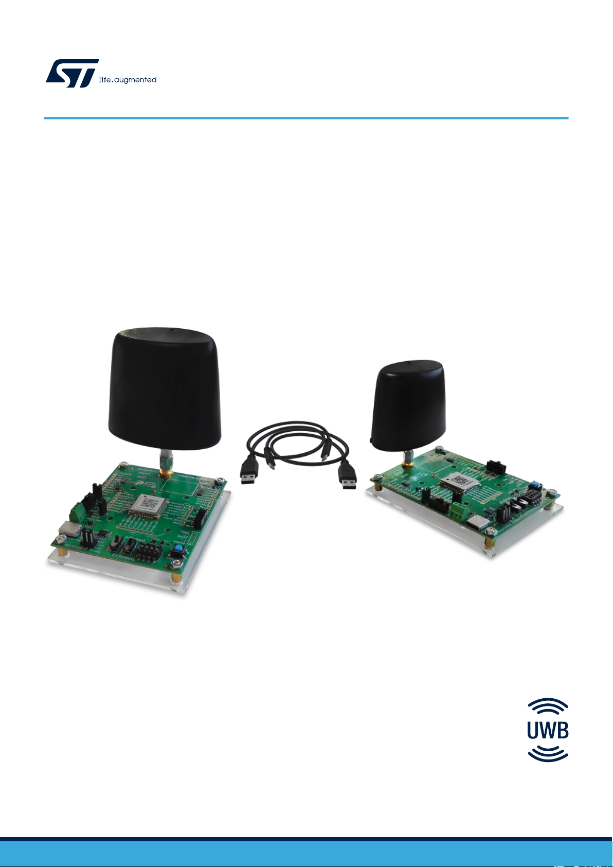
This document explains how to get started quickly with the B-UWB-MEK1 module evaluation kit. B-UWB-MEK1 includes
Evaluation boards equipped with the STM32-based B-UWB-MOD1 UWB module designed to test advanced positioning and
tracking technology in real conditions, or to be embedded directly into a ready-to-use indoor location system. The Evaluation
boards can be used both as fixed or mobile devices for complete system evaluation.
The quick start guide covers such aspects as hardware content, system introduction, software tools, 1D and 3D measurements,
device addition, system update, and support.
Figure 1. B-UWB-MEK1 module evaluation kit
Picture is not contractual.
UM2798 - Rev 1 - March 2021
For further information contact your local STMicroelectronics sales office.
www.st.com
Page 2
1 Unpack hardware
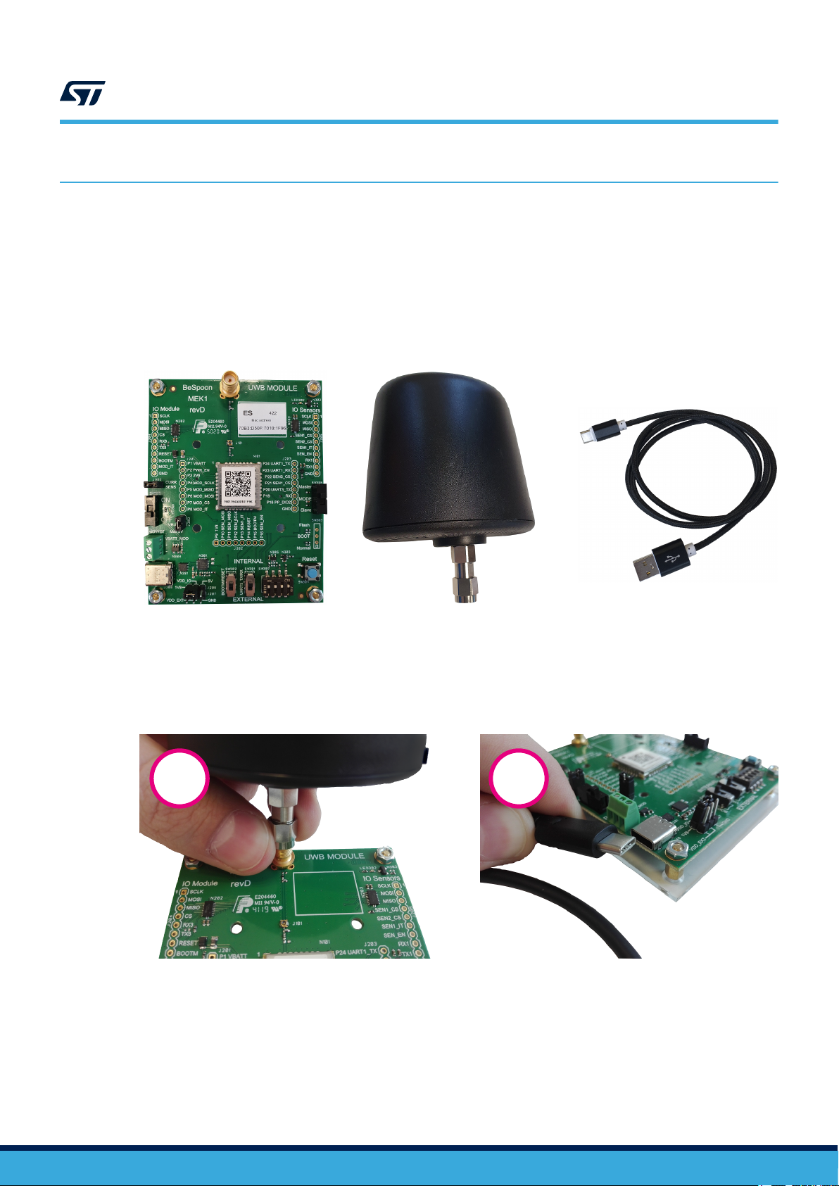
Check the content
• B-UWB-MEK1 boards
• Omnidirectional antennas
• USB Type-C® to USB Type-A cables
1. B-UWB-MEK1 is available in packs of two boards. The number of packs needed depends on the use case.
Unpack hardware
(1)
, equipped with the B-UWB-MOD1 modules mounted on PERSPEX® panels
Figure 2. B-UWB-MEK1 board, antenna and cable
UM2798
Assemble the boards
1. Screw the antenna carefully (maximum torque from 0.3 to 0.6 N.m)
2. Plug the USB cable
Figure 3. B-UWB-MEK1 antenna and cable connection
1 2
UM2798 - Rev 1
page 2/25
Page 3

UM2798
Come to know the system
2 Come to know the system
2.1 Delivery pack
The software development kit (SDK) included in the delivery pack contains documentation and the related
software toolchain, to make the development process based on B-UWB-MEK1 and B-UWB-MOD1 easier.
Make sure to decompress the SDK folder received as a compressed archive into a path without any whitespace.
Note: This quick start guide and its appendices are based on system version 3.x. For update or advanced system
features, refer to the comprehensive user documentation presented in Reference documentation.
2.2 Configurations
B-UWB-MEK1 is designed to test ultra-wideband (UWB) positioning and tracking independently, or to be used
within an existing location system based on this technology.
This quick start guide provides an easy access to the main functionalities by presenting three basic modes for a
setup composed of up to 6 boards:
• Filtered 1D measurement
• Raw 1D measurement
• 3D single self-positioning
Appendix Add devices explains the configuration steps to use more devices.
2.3
Note: Arm is a registered trademark of Arm Limited (or its subsidiaries) in the US and/or elsewhere.
Board overview
B-UWB-MEK1 boards are built around the ultra-compact surface mounted B-UWB-MOD1 UWB module, which is
the kernel of various adjustable device-centric and server-centric location configurations.
B-UWB-MOD1 features the STM32L476JE 32-bit microcontroller based on the Arm® 32-bit Cortex®‑M4 CPU with
FPU.
All B-UWB-MEK1 boards have the same pre-settings and functionalities, to be alternatively in master or
secondary mode, as a fixed or mobile device for measurement and positioning. The green LED indicates the
board synchronization status, the red LED shows the power supply.
Each board has two switches and one button to control roles and functions as shown in Figure 4:
• ON / OFF - alternate the power switch
• Master / Secondary - alternate the MODE switch
• Reset - press the Reset button
UM2798 - Rev 1
page 3/25
Page 4
Green LED
power supply
on/off
Power
switch
UM2798
Board overview
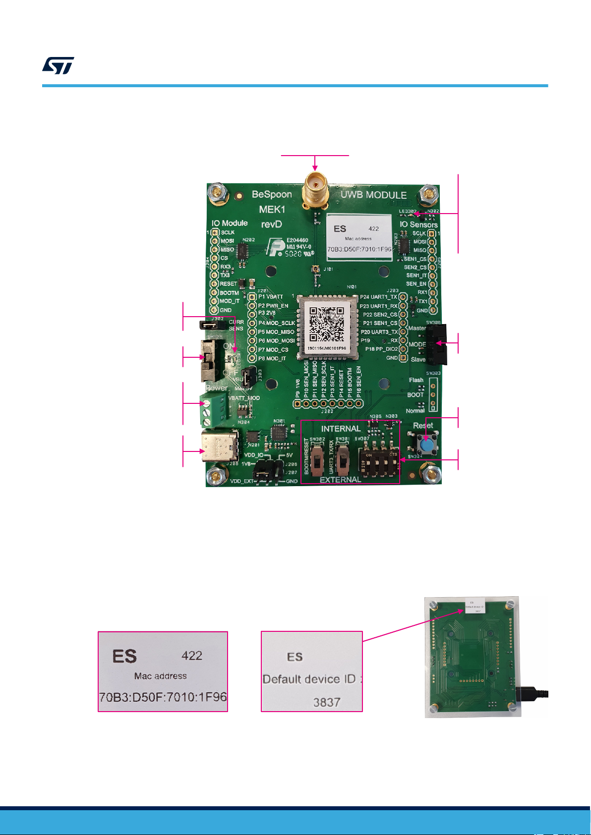
Figure 4. B-UWB-MEK1 board front view
Standard SMA female
antenna connector
Red LED
synchronization of
secondary boards
slow blinking:
not synchronized
quick blinking:
synchronized
MODE
switch
Screw terminal
wired power supply
input calibration
5 V / 200 mA
USB Type-C
connector
power supply & data
®
1. For advanced development.
Keep in INTERNAL upper position unless specified otherwise.
Zoom on device information labels
The labels on the front and back sides of the board provide the board specific identifiers.
Figure 5. B-UWB-MEK1 labels on the front side and back side
Front-side label Back-side label
Reset
button
Board configuration
switches
(1)
UM2798 - Rev 1
page 4/25
Page 5

2.4 Software tools
2.4.1 Driver
Windows® systems require a Silicon Labs' CP210x driver to connect. For Ubuntu®, refer directly to MOD1/MEK1
programming tool.
UM2798
Software tools
Windows 10
®
The system installs the driver itself within a few seconds when the board is plugged onto the USB port.
If the automatic installation does not happen, Windows® drivers are also provided in the delivery package in \mo
d1_SDK_3.x.x-rxxxxx\tools\exe\CP210x_Universal_Windows_Driver.zip.
Older Windows® versions
CP210x drivers for older Windows® versions are available on Silicon Labs' website at www.silabs.com/
developers/usb-to-uart-bridge-vcp-drivers.
2.4.2 MOD1/MEK1 programming tool
This application enables users to set their boards for different configurations by providing access to the module
memory.
Windows
Path: \mod1_SDK_3.x.x-rxxxxx\tools\exe\bspmoduletoolsgui_3.x.x_amd64.exe
Installation: double-click on the file to open the application directly.
Ubuntu
Path: \mod1_SDK_3.x.x-rxxxxx\tools\deb\bspmoduletoolsgui_3.x.x_amd64.deb
Installation:
1. Open Terminal
2.
3. Enter the following command:
4. Enter the password
®
®
Access the deb directory in the SDK by using Linux® command cd (change directory) and entering the
corresponding path.
In the example below, the user is navigating from the home directory and the SDK directory is stored on the
Desktop:
cd Desktop/mod1_SDK_3.x.x_REVISION/tools/deb
./install_bspmoduletools_all.sh
The installation script starts to run. The installation script ends with Bespoon DKMS package correctly
installed !
2.4.3 Trace tool
Various terminal applications can be used as UART trace tools to read distances. On Windows®, use for instance
Tera Term, an application provided by the Open Source Development Network at osdn.net/projects/ttssh2/.
Ubuntu® systems already include the Minicom serial communication application.
Follow the steps below to configure the trace tool:
Step 1. Select the board used as the master in the upcoming procedures.
Step 2. Set its MODE switch accordingly.
Step 3. Connect the board to the computer via the USB.
Step 4. Turn on the board with the power switch and open the trace tool.
Step 5. Select [Serial] and the port of the corresponding USB connection.
UM2798 - Rev 1
page 5/25
Page 6

Step 6. In [Setup]>[Serial port], enter the following settings:
– Baud rate 921600 bauds
– Data 8 bits
– Parity none
– Stop bit 1
– Flow control none
Step 7. Go to [Setup]>[Save setup].
Step 8. Save the setup (*.ini file) in the suggested program directory.
Step 9. Press the Reset button to reset the board.
The terminal displays: MEK MASTER ANCHOR [ID] STARTED
UM2798
Software tools
UM2798 - Rev 1
page 6/25
Page 7

3 Filtered 1D measurement
The filtered 1D measurement mode improves the accuracy of 1D measurements by post-processing the collected
data with a filter. It is the default mode on B-UWB-MEK1 boards.
Figure 6. Filtered 1D measurement
UM2798
Filtered 1D measurement
1 master board and up to 5 secondary boards
E
F
F
F
F
F
DME
A
DMA
M = master, A, B, C, D, E = secondary
distances = DMA, DMB, DMC, DMD, DME,
provided at M interface as filtered data (F)
Step 1. Check that the trace tool is closed.
Step 2. On the master board, check that the MODE switch is in position Master.
Step 3. Connect the master board to the computer.
– If no other B-UWB-MEK1 location mode was used before, skip steps 4 to 8 and jump to step 9
directly since filtered 1D measurement is the default setting.
– Otherwise, proceed with step 4.
Step 4. Open the MOD1/MEK1 programming tool and use the power switch to turn on the board.
Step 5. In the menu on the right, select the serial port of the master board.
The programming tool displays a progress bar and device information.
B
DMB
M
DMC
D
DMD
C
UM2798 - Rev 1
Step 6. In [Localization]>[TYPE], select [1D_FILT].
Step 7. Click on [Apply Localization Parameters].
Step 8. Wait until the progress bar displays OK.
Step 9. On the secondary boards, set the MODE switch in the position opposite to Master
Step 10. Supply the secondary boards with 5 V power and use their power switches to turn them on.
Step 11. In the trace tool, open a new connection.
page 7/25
Page 8
Step 12. Reset the master board.
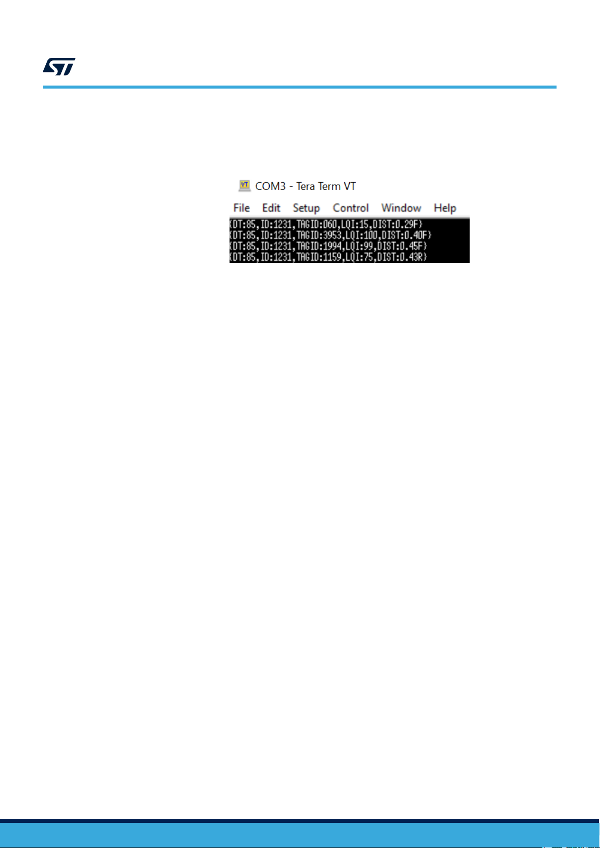
The terminal displays filtered 1D measurement logs:
– DT (delta): time between measures in milliseconds (until decimal point)
– ID: device ID of the master board
– TAGID: device ID of the secondary board (each board on a separate line)
– LQI (link quality indicator): signal strength in percent
– DIST (distance): measurement between master and secondary in meters
– F at line end: indicates a filtered value
UM2798
Filtered 1D measurement
Figure 7. Filtered 1D measurement trace
UM2798 - Rev 1
page 8/25
Page 9

4 Raw 1D measurement
The raw 1D measurement mode provides 1D measurement data without any post-processing.
UM2798
Raw 1D measurement
Figure 8. Raw 1D measurement
1 master board and up to 5 secondary boards
E
R
R
R
R
R
DME
A
DMA
M = master, A, B, C, D, E = secondary
distances = DMA, DMB, DMC, DMD, DME
provided at M interface as raw data (R)
Step 1. Check that the trace tool is closed.
Step 2. On the master board, check that the MODE switch is in position Master.
Step 3. Connect the master board to the computer.
Step 4. Open the MOD1/MEK1 programming tool and use the power switch to turn on the board.
Step 5. In the menu on the right, select the serial port of the master board.
The programming tool displays a progress bar and device information.
Step 6. In [Localization]>[TYPE], select [1D_RAW].
B
DMB
M
DMC
D
DMD
C
Step 7. Click on [Apply Localization Parameters].
Step 8. Wait until the progress bar displays OK.
Step 9. On the secondary boards, set the MODE switch in the position opposite to Master
Step 10. Supply the secondary boards with 5 V power and use their power switches to turn them on.
Step 11. In the trace tool, open a new connection.
UM2798 - Rev 1
page 9/25
Page 10

Step 12. Reset the master board.
The terminal displays raw 1D measurement logs:
– DT (delta): time between measures in milliseconds (until decimal point)
– ID: device ID of the master board
– TAGID: device ID of the secondary board (each board on a separate line)
– LQI (link quality indicator): signal strength in percent
– DIST (distance): measurement between master and secondary in meters
– R at line end: indicates a raw value
UM2798
Raw 1D measurement
Figure 9. Filtered 1D measurement trace
UM2798 - Rev 1
page 10/25
Page 11

5 3D single self-positioning
3D single self-positioning is ideal to track one single, fast-moving mobile device very precisely, at very high speed.
Figure 10. 3D single self-positioning
1 mobile master board and 3 to 5 fixed secondary boards
(5 recommended)
UM2798
3D single self-positioning
E
x, y, z
D
M = master, A, B, C, D, E = secondary
position (x, y z) of M computed and provided at M interface
Step 1. Deploy the setup (secondary boards):
Step 1a. Position the boards
Step 1b. Define a fixed reference point to measure the 3D coordinates of the fixed secondary board
antennas according to the coordinate system.
Figure 11. 3D coordinate system
z
p
0
y
x
p
M
A
B
0 = defined reference point
p = secondary board position (antenna center)
Coordinates can be negative.
C
UM2798 - Rev 1
Step 1c. Measure the coordinates of each fixed secondary board according to this fixed reference.
Step 2. Prepare the master board:
Step 2a. Check that the trace tool is closed.
Step 2b. Check that the MODE switch is in position Master and use the power switch to turn on the
board.
Step 2c. Connect the master board to the computer
page 11/25
Page 12

Step 3. Configure the master board in the MOD1/MEK1 programming tool:
Step 3a. In the menu at the top of the right area, select the serial port of the master board.
The programming tool displays a progress bar and device information.
Step 3b. In [Localization]>[TYPE], select [3D_SELF].
Step 3c. In [Localization]>[INFRA], click on [+] to add the secondary boards to the configuration:
◦ DeviceID: enter the device IDs of the secondary boards
◦ x, y, z: enter the coordinates of the secondary boards in meters, using a point as
decimal separator
Step 3d. Click on [Apply Localization Parameters].
Step 3e. Wait until the progress bar displays OK.
Step 4. Start 3D single self-positioning:
Step 4a. Check that the MODE switch is in the position opposite to Master on each secondary board.
Step 4b. Supply the secondary boards with 5 V power and use their power switches to turn them on.
Step 4c. In the trace tool, open a new connection.
Step 4d. Reset the master board.
The terminal displays the following traces:
– MEK MASTER ANCHOR [ID] STARTED
– DEV[Device ID] for each board of the configuration
– 3D single self-positioning logs
UM2798
3D single self-positioning
Figure 12. Filtered 3D single self-positioning trace
– DT (delta): time between measures in milliseconds (until decimal point)
– ID: device ID of the master board being located
– X, Y, Z: 3D coordinates of the master board in meters
UM2798 - Rev 1
page 12/25
Page 13

6 Go ahead or ask for support
This quick start guide deals with the most frequent B-UWB-MEK1 use cases requiring no customization. To get
access to more functions, look for the adapted documentation in Reference documentation.
For support or information about standardized as well as customized solutions, refer to the UWB and product
pages on www.st.com, or to the nearest STMicroelectronics office.
UM2798
Go ahead or ask for support
UM2798 - Rev 1
page 13/25
Page 14

UM2798
Reference documentation
Appendix A Reference documentation
Table 1 presents a summary of the documents available for B-UWB-MEK1. Refer to the STMicroelectronics
website at www.st.com for the latest updates.
Table 1. B-UWB-MEK1 related documents
Document User profile Source
B-UWB-MEK1 data brief Basic
www.st.comB-UWB-MOD1 data brief Basic
B-UWB-MEK1 quick start guide (this document) Basic
3D mode visualization in the location client Advanced
Antenna offset adaptation Advanced
Filter adjustment for the location algorithm Expert
GPS-like mode within an existing RTLS Advanced
SFI modification Expert
Single self-positioning with tags Advanced
Information about the UWB system topologies Expert
SDK advanced documentation Expert
SDK
UM2798 - Rev 1
page 14/25
Page 15

Appendix B Add devices
B.1 Prerequisites and configurations
This appendix applies to measurement and positioning constellations with more than six devices in the following
modes:
• Filtered and raw 1D measurement (refer to B.2)
• 3D single self-positioning (refer to B.3)
B.2 Filtered and raw 1D measurement with additional boards
This section details multiple 1D measurements with filtering limited to seven devices or without any postprocessing. Refer to Section 3 and Section 4 for the description of the plain filtered 1D measurement
and raw 1D measurement respectively.
Figure 13. Multiple filtered and raw 1D measurement
UM2798
Add devices
1 master board, 6 to 58 secondary boards
M = master, A, B, C, D, E, F... = secondary
distances = DMA, DMB, DMC, DMD, DME, DMF…
provided at M interface
E
F
DME
F/R
F/R
F/R
F/R
F/R
F/R
F/R
R
...
DMF
A
M
DMA
DMB
DMC
B
filtered data (F) for 7 measurements + raw data (R)
or
raw data (R) for all measurements
Step 1. Check that the trace tool is closed.
Step 2. On one board selected as the master board, put the MODE switch in position Master.
Step 3. On all other boards, put the MODE switch in the position opposite to Master.
R
D
DMD
C
UM2798 - Rev 1
page 15/25
Page 16

Filtered and raw 1D measurement with additional boards
Step 4. Adjust the rate parameters of each board, one after another:
Step 4a. Connect the board to the computer.
Step 4b. Open the MOD1/MEK1 programming tool and use the power switch to turn on the board.
Step 4c. In the menu on the right, select the serial port of the board.
The programming tool displays a progress bar and device information.
Step 4d. In [Settings]>[PROTOCOL RATE], click on [Wizard].
Step 4e. Select the base rate
Step 4f. In the upcoming message box, select [NO].
Step 4g. Enter the number of secondary boards used in the installation and validate.
Step 4h. Click on [Apply Settings].
Step 4i. Wait until the progress bar displays OK.
Step 5. Set the location system parameters:
Step 5a. Check that the master board is connected to the computer and turned on.
Step 5b. In the MOD1/MEK1 programming tool, in the menu at the top of the right area, select the
serial port of the master board.
The programming tool displays a progress bar and device information.
Step 5c. In [Localization]>[TYPE], select [1D_FILT] or [1D_RAW].
Step 5d. Click on [Apply Localization Parameters].
Step 5e. Wait until the progress bar displays OK.
UM2798
Step 6. Supply the secondary boards with 5 V power and use their power switches to turn them on.
Step 7. In the trace tool, open a new connection.
Step 8. Reset the master board.
The terminal displays 1D measurement logs:
– DT (delta): time between measures in milliseconds (until decimal point)
– ID: device ID of the master board
– TAGID: device ID of the secondary board (each board on a separate line)
– LQI (link quality indicator): signal strength in percent
– DIST (distance): measurement between master and secondary in meters
– F at line end: indicates a filtered value
– R at line end: indicates a raw value
UM2798 - Rev 1
page 16/25
Page 17

3D single self-positioning with an augmented constellation
B.3 3D single self-positioning with an augmented constellation
3D single self-positioning is ideal to track one single, fast-moving mobile device very precisely, at very high
speed. Adding secondary boards to the 3D self positioning constellation of fixed devices increases robustness
and enables the coverage of larger areas. Refer to Section 5 for the description of the plain 3D single
self-positioning.
Figure 14. 3D single self-positioning with additional fixed devices
1 mobile master board
6 to 52 fixed secondary boards
E
UM2798
F
D
x, y, z
M
A
M = master, A, B, C, D, E, F... = secondary
position of M computed and provided at M interface
Step 1. Check that the trace tool is closed.
Step 2. On one board selected as the master board, put the MODE switch in position Master.
Step 3. On all other boards, put the MODE switch in the position opposite to Master.
Step 4. Adjust the rate parameters of each board, one after another:
Step 4a. Connect the board to the computer.
Step 4b. Open the MOD1/MEK1 programming tool and use the power switch to turn on the board.
Step 4c. In the menu on the right, select the serial port of the board.
The programming tool displays a progress bar and device information.
Step 4d. In [Settings]>[PROTOCOL RATE], click on [Wizard].
Step 4e. Select the base rate
Step 4f. In the upcoming message box, select [YES].
Step 4g. Enter the number of secondary boards used in the installation and validate.
Step 4h. Click on [Apply Settings].
Step 4i. Wait until the progress bar displays OK.
C
B
UM2798 - Rev 1
page 17/25
Page 18

Step 5. Set the constellation of fixed secondary boards:
Step 5a. Position the secondary boards:
◦ Ensure intervals of at least 1.5 m between the devices
◦ Avoid alignments
◦ Avoid coplanarity
Step 5b. Define a fixed reference point to measure the 3D coordinates of the fixed secondary board
antennas according to the coordinate system.
Figure 15. 3D coordinate system
z
p
UM2798
3D single self-positioning with an augmented constellation
0 = defined reference point
p
p = secondary board position (antenna center)
0
y
x
Coordinates can be negative.
Step 5c. Measure the coordinates of each fixed secondary board according to this fixed reference.
Step 6. Set the location system parameters:
Step 6a. Check that the master board is connected to the computer and turned on.
Step 6b. In the MOD1/MEK1 programming tool, in the menu at the top of the right area, select the
serial port of the master board.
The programming tool displays a progress bar and device information.
Step 6c. In [Localization]>[TYPE], select [3D_SELF].
Step 6d. In [Localization]>[INFRA], click on [+] to add the secondary boards to the configuration:
◦ DeviceID: enter the device IDs of the secondary boards
◦ x, y, z: enter the coordinates of the secondary boards in meters, using a point as
decimal separator
Step 6e. Click on [Apply Localization Parameters].
Step 6f. Wait until the progress bar displays OK.
Step 7. Supply the secondary boards with 5 V power and use their power switches to turn them on.
Step 8. In the trace tool, open a new connection.
Step 9. Reset the master board.
The terminal displays the following traces:
– MEK MASTER ANCHOR [ID] STARTED
– DEV[Device ID] for each board of the configuration
– 3D single self-positioning logs:
◦ DT (delta): time between measures in milliseconds (until decimal point)
◦ ID: device ID of the master board being located
◦ X, Y, Z: 3D coordinates of the master board in meters
UM2798 - Rev 1
page 18/25
Page 19

Appendix C Update the system
C.1 Update the system with default settings
This section is about:
• Upgrading firmware
• Resetting module and location infrastructure parameters
Follow this procedure to upgrade the system without integrating any particular module setting or location
infrastructure parameters. To update firmware with customized settings, refer to C.2.
Repeat the procedure with every board used in the infrastructure.
Step 1. Connect the board to the computer via the USB.
Step 2. Open the MOD1/MEK1 programming tool and use the power switch to turn on the board.
Step 3. Check that the firmware version displayed on the right side is the latest one (Version 3.x) and proceed.
If this is not the case, ask for support from the nearest STMicroelectronics office.
Step 4. In the menu on the right, select the serial port of the board.
Step 5. Wait until the progress bar on the right displays OK.
UM2798
Update the system
C.2
Step 6. In the Program tab, check that the following options are properly set:
– [FLASH Firmware]: 3.x. MEK1 Firmware
– [FLASH Settings]: MEK1 Default Settings
– [FLASH Localization]: Default Localization Parameters
Step 7. Click on the [Flash] field at the bottom of the Program tab.
Step 8. Wait until the progress bar on the right displays OK.
The B-UWB-MEK1 boards and infrastructure are now up to date.
Update the system with customized settings
This section is about:
• Upgrading firmware
• Integrating customized module, customized location infrastructure parameters, or both
Follow this procedure to update firmware by considering specific conditions, either customized by
STMicroelectronics before delivery or tuned on site.
Repeat the procedure with every board used in the infrastructure.
Step 1. Connect the board to the computer via the USB.
Step 2. Open the MOD1/MEK1 programming tool and use the power switch to turn on the board.
Step 3. Check that the firmware version displayed on the right side is the latest one (Version 3.x) and proceed.
If this is not the case, ask for support from the nearest STMicroelectronics office.
Step 4. In the menu on the right, select the serial port of the board.
UM2798 - Rev 1
Step 5. Wait until the progress bar on the right displays OK.
Step 6. Export the customized module settings, the location infrastructure settings, or both:
– For module settings, in the Settings tab, click on [Export settings] and save the exported file.
– For location infrastructure setting, in the Localization tab, click on [Export parameters] and save
the exported file.
– For module and location infrastructure settings, export and save both files
page 19/25
Page 20

Update the system with customized settings
Step 7. In the Program tab:
Step 7a. Select [FLASH Firmware] and 3.x. MEK1 Firmware
Step 7b. Import the needed customized settings:
◦ For module settings, select [FLASH Settings] and Custom Settings File
◦ For location infrastructure setting, select [FLASH Localization] and Custom
Localization File
◦ For module and location infrastructure settings, select both files
Step 7c. For each import, click on the file icon to browse and find the previously saved file
Step 8. Click on the [Flash] field at the bottom of the Program tab.
Step 9. Wait until the progress bar on the right displays OK.
The B-UWB-MEK1 boards and infrastructure are now up to date with customized settings.
UM2798
UM2798 - Rev 1
page 20/25
Page 21

Revision history
UM2798
Table 2. Document revision history
Date Revision Changes
17-Mar-2021 1 Initial release.
UM2798 - Rev 1
page 21/25
Page 22

UM2798
Contents
Contents
1 Unpack hardware ..................................................................2
2 Come to know the system .........................................................3
2.1 Delivery pack ..................................................................3
2.2 Configurations .................................................................3
2.3 Board overview ................................................................3
2.4 Software tools .................................................................5
2.4.1 Driver .................................................................5
2.4.2 MOD1/MEK1 programming tool .............................................5
2.4.3 Trace tool ..............................................................5
3 Filtered 1D measurement ..........................................................7
4 Raw 1D measurement..............................................................9
5 3D single self-positioning.........................................................11
6 Go ahead or ask for support ......................................................13
Appendix A Reference documentation ................................................14
Appendix B Add devices .............................................................15
B.1 Prerequisites and configurations .................................................15
B.2 Filtered and raw 1D measurement with additional boards ............................15
B.3 3D single self-positioning with an augmented constellation...........................17
Appendix C Update the system .......................................................19
C.1 Update the system with default settings ...........................................19
C.2 Update the system with customized settings .......................................19
Revision history .......................................................................21
Contents ..............................................................................22
List of tables ..........................................................................23
List of figures..........................................................................24
UM2798 - Rev 1
page 22/25
Page 23

UM2798
List of tables
List of tables
Table 1. B-UWB-MEK1 related documents ....................................................... 14
Table 2. Document revision history.............................................................21
UM2798 - Rev 1
page 23/25
Page 24

UM2798
List of figures
List of figures
Figure 1. B-UWB-MEK1 module evaluation kit .....................................................1
Figure 2. B-UWB-MEK1 board, antenna and cable ..................................................2
Figure 3. B-UWB-MEK1 antenna and cable connection ............................................... 2
Figure 4. B-UWB-MEK1 board front view .........................................................4
Figure 5. B-UWB-MEK1 labels on the front side and back side ..........................................4
Figure 6. Filtered 1D measurement.............................................................7
Figure 7. Filtered 1D measurement trace .........................................................8
Figure 8. Raw 1D measurement ...............................................................9
Figure 9. Filtered 1D measurement trace ........................................................ 10
Figure 10. 3D single self-positioning ............................................................ 11
Figure 11. 3D coordinate system .............................................................. 11
Figure 12. Filtered 3D single self-positioning trace .................................................. 12
Figure 13. Multiple filtered and raw 1D measurement ................................................ 15
Figure 14. 3D single self-positioning with additional fixed devices ........................................ 17
Figure 15. 3D coordinate system .............................................................. 18
UM2798 - Rev 1
page 24/25
Page 25

UM2798
IMPORTANT NOTICE – PLEASE READ CAREFULLY
STMicroelectronics NV and its subsidiaries (“ST”) reserve the right to make changes, corrections, enhancements, modifications, and improvements to ST
products and/or to this document at any time without notice. Purchasers should obtain the latest relevant information on ST products before placing orders. ST
products are sold pursuant to ST’s terms and conditions of sale in place at the time of order acknowledgement.
Purchasers are solely responsible for the choice, selection, and use of ST products and ST assumes no liability for application assistance or the design of
Purchasers’ products.
No license, express or implied, to any intellectual property right is granted by ST herein.
Resale of ST products with provisions different from the information set forth herein shall void any warranty granted by ST for such product.
ST and the ST logo are trademarks of ST. For additional information about ST trademarks, please refer to www.st.com/trademarks. All other product or service
names are the property of their respective owners.
Information in this document supersedes and replaces information previously supplied in any prior versions of this document.
© 2021 STMicroelectronics – All rights reserved
UM2798 - Rev 1
page 25/25
 Loading...