

Page 1

AN5325
Application note
Getting started with the CORDIC accelerator using STM32CubeG4 MCU Package
Introduction
This document applies to STM32CubeG4 MCU Package, for use with STM32G4 Series microcontrollers.
The CORDIC is a hardware accelerator designed to speed up the calculation of certain mathematical functions, notably
trigonometric and hyperbolic, compared to a software implementation.
The accelerator is particularly useful in motor control and related applications, where algorithms require frequent and rapid
conversions between rectangular (x, y) and angular (amplitude, phase) co-ordinates.
This application note describes how the CORDIC accelerator works on STM32G4 Series microcontrollers, its capabilities and
limitations, and evaluates the speed of execution for certain calculations compared with equivalent software implementations.
The example code to accompany this application note is included in the STM32CubeG4 MCU Package available on
www.st.com. The examples run on the NUCLEO-G474RE board.
AN5325 - Rev 2 - March 2021
For further information contact your local STMicroelectronics sales office.
www.st.com
Page 2

1 General information
The STM32CubeG4 MCU Package runs on STM32G4 Series microncontrollers, based on Arm® Cortex®-M4
processors.
Note: Arm is a registered trademark of Arm Limited (or its subsidiaries) in the US and/or elsewhere.
AN5325
General information
AN5325 - Rev 2
page 2/20
Page 3
2 CORDIC introduction
The CORDIC (coordinate rotation digital computer) is a low-cost successive approximation algorithm for
evaluating trigonometric and hyperbolic functions.
Originally presented by Jack Volder in 1959, it was widely used in early calculators.
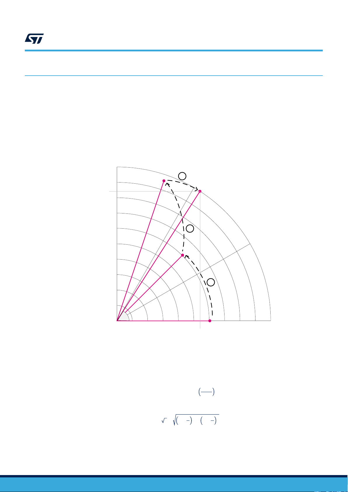
In trigonometric (circular) mode, the sine and cosine of an angle θ are determined by rotating the vector [0.61,
0] through decreasing angles tan-1(2-n) (n = 0, 1, 2,...) until the cumulative sum of the rotation angles equals the
input angle. The x and y cartesian components of the rotated vector then correspond respectively to the cosine
and sine of
(~1.65) over the course of the calculation.
θ.
This is illustrated in Figure 1 for an angle of 60 deg. The vector undergoes a scaling by 1/0.61
90°
y (sin q)
0.8
AN5325
CORDIC introduction
Figure 1. CORDIC circular mode operation
3
60°
0.6
0.4
2
30°
1
0.2
q
x (cos q)
0°
Inversely, the angle of a vector [x, y] is determined by rotating 0.61[x, y] through successively decreasing angles
to obtain the unit vector [1, 0]. The cumulative sum of the rotation angles gives the angle of the original vector,
corresponding to arctangent (y/x).
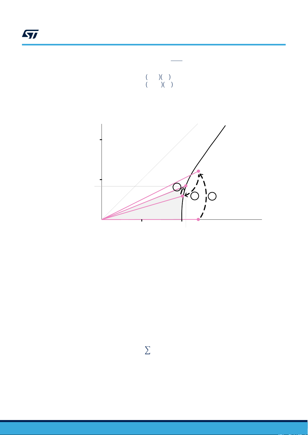
The CORDIC algorithm can also be used for calculating hyperbolic functions (sinh, cosh, atanh) by replacing the
circular rotations by hyperbolic angles tanh-1(2-j) (j = 1, 2, 3...), see Figure 2. CORDIC hyperbolic mode operation.
The natural logarithm is a special case of the inverse hyperbolic tangent, obtained from the identity:
x + 1
ln x = 2.tanh
−1
x − 1
The square root function is also a special case of the inverse hyperbolic tangent. When calculating the atanh the
CORDIC also calculates √(cosh2 t - sinh2 t) as a by-product. So the square root is obtained from:
x = x +
1
4
2
− x −
2
1
4
AN5325 - Rev 2
Additional functions are calculated from the above using appropriate identities:
page 3/20
Page 4
AN5325
Limitations
tanh x =
ex= sinℎ x + cosℎ x
log2x = log2e ln x = 1.442695041 ln x
log10x = log10e ln x = 0.434294482 ln x
The CORDIC algorithm lends itself to hardware implementation since there are no multiplications involved (the
fixed scaling factor 0.61 is pre-loaded). Only add and shift operations are performed. This also means that it is
ideally suited to integer arithmetic.
Figure 2. CORDIC hyperbolic mode operation
1.0
0.5
y (sinh t)
sinh x
cosh x
3
2
hyperbola: x
1
2
- y
2
= 1
2.1
t/2
0.5
1.0
x (cosh t)
Limitations
In circular mode, the CORDIC converges for all angles in the range -π to π radians. The use of fixed point
representation means that input and output values must be in the range -1 to +1. Input angles in radians must be
multiplied by 1/π and output angles must be multiplied by π to convert back to radians.
The modulus must be in the range 0 to 1, whether converting from polar to rectangular or rectangular to polar.
This means that phase(1.0, 1.0) gives false results since the modulus (√2) is out of range and saturates the
CORDIC engine, even if only the phase is needed.
In hyperbolic mode, x = cosh t being defined only for x ≥ 1, all inputs and outputs are divided by 2 to remain in
the fixed point numeric range. Hence the CORDIC without additional scaling supports values of x = cosh(t) in the
range 1 to 2 (ie. 0.5 to 1 after division by 2), which corresponds to hyperbolic angle magnitude t in the range 0 to
1.317 (cosh-1 2).
It is possible to increase the range by additional scaling. However, the CORDIC algorithm stops converging for |t|
> 1.118. This is because the successive approximation step size, |δtj| is equal to the magnitude of the hyperbolic
angle |tanh-1 2-j|, where j is the iteration number. So as j increases, the step size decreases. It so happens that as
j tends to infinity, the sum of |δtj| tends to 1.118:
∞
tanh−12
j = 1
This is illustrated in Figure 3. Hyperbolic convergence limit.
− j
= 1.118
AN5325 - Rev 2
page 4/20
Page 5
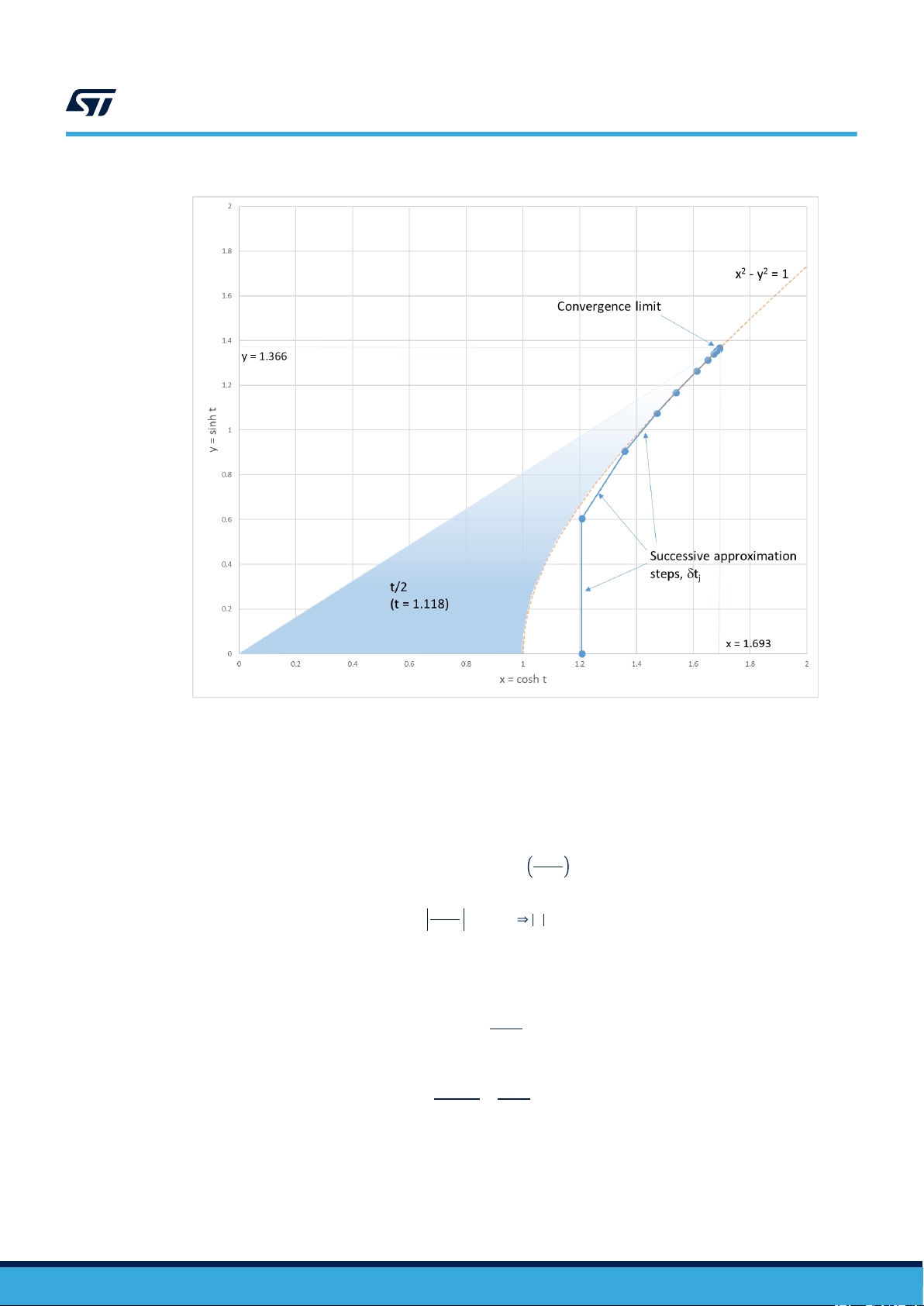
Figure 3. Hyperbolic convergence limit
AN5325
Limitations
So 1.118 is the effective limit for the hyperbolic sine and cosine functions’ input magnitude. If the value of t is
constrained to be smaller than this limit, then the CORDIC is used directly. Otherwise, the magnitude of t must
be tested and if it is above the limit, an alternative software algorithm must be used, such as the math.h library
functions coshf() and sinhf().
The magnitude of the atanh function output is similarly limited to 1.118, hence the input magnitude is limited to
tanh 1.118 = 0.806.
As previously stated, the natural log uses the identity:
ln x =
x − 1
x + 1
−1
2.tanh
Since the limit for the atanh input magnitude is 0.806, then:
x + 1
< 0.806 x < 9.35
x − 1
Hence the limit for the natural log input is 9.35. Furthermore, the input must be scaled by the appropriate power of
2, such that 2-n.(x+1) < 1, to avoid overflowing the fixed point numerical format.
In a similar way the convergence limit for the sqrt function is calculated. Since the limit for the atanh function is
given by:
tanh t =
sinh t
cosh t
≤ 0.806
and the inputs to the atanh function are sinh t and cosh t, then the input to the square root function must satisfy
the expression:
x − 0.25
x + 0.25
=
sinh t
cosh t
≤ 0.806
Hence x ≤ 2.34. Again, scaling must be applied such that 2-n.(x+0.25) < 1 to avoid saturation.
AN5325 - Rev 2
page 5/20
Page 6
2.2 Convergence rate and precision
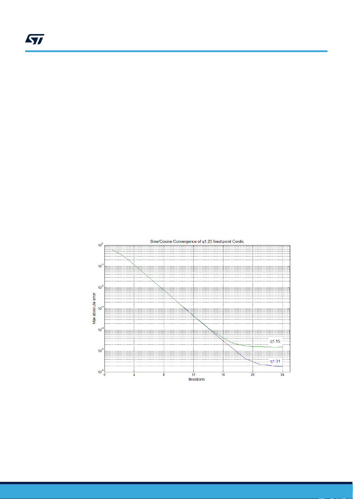
In circular mode, the CORDIC algorithm converges at a rate of 1 binary digit per iteration. This means that 16
iterations are required to achieve 16-bit precision. The maximum achievable precision is limited by the number of
bits in the CORDIC “engine” (the shifters and adders, as well as the table used to store the successive rotation
angles), and of course in the input and output registers. The CORDIC unit in the STM32G4 Series supports 16-bit
and 32-bit input and output data, and has an internal precision of 24 bits.
Figure 4. CORDIC convergence (circular mode) shows the rate of convergence for the CORDIC in circular mode.
The curve labeled “q1.15” uses 16-bit input and output data. The curve labeled “q1.31” uses 32-bit data. In both
cases the CORDIC “engine” is 24-bit. When the maximum residual error approaches the limit for 16-bit precision
-16
(2
= 1.5 x 10⁻⁵), the quantization error caused by truncating the result to 16 bits becomes dominant, and the
curve flattens out, even though the CORDIC engine continues to converge. For 32-bit data it is the quantization
error of the CORDIC engine itself which starts to become significant after around 20 iterations. After 24 iterations,
the successive rotation angle becomes zero and no more convergence is possible. The maximum residual error
in this case is 1.9 x 10⁻⁶, which corresponds to 19-bit precision.
In hyperbolic mode, a particularity of the algorithm requires that certain iterations must be performed twice in
order to converge over the whole range. In a 24-bit CORDIC, the 4th and the 14th iterations are repeated,
that is to say the same rotation angle is applied twice in a row instead of dividing by two. This means that the
convergence is not linear, as seen in Figure 5. CORDIC convergence (hyperbolic mode). The error decreases
more gradually at the beginning and remains the same between iteration 14 and 15. Therefore the CORDIC takes
two more iterations to achieve the same precision in hyperbolic mode than in circular mode.
Square root is an exception to the above. It converges approximately twice as fast as the other hyperbolic mode
functions.
AN5325
Convergence rate and precision
Figure 4. CORDIC convergence (circular mode)
AN5325 - Rev 2
page 6/20
Page 7

Figure 5. CORDIC convergence (hyperbolic mode)
AN5325
Convergence rate and precision
AN5325 - Rev 2
page 7/20
Page 8

3 Code examples and performance
3.1 Acceleration example: one-off calculation in software
The CORDIC unit is designed primarily to accelerate the evaluation of mathematical expressions compared to an
equivalent function from a software library such as math.h.
An example program is in the STM32CubeG4 MCU Package, under \Projects\NUCLEOG474RE\Examples_LL\CORDIC\CORDIC_CosSin. This example performs a polar to rectangular conversion
using the cosine function. The example code uses the LL (low level) driver, which has less overhead than the HAL
driver. Executing the function comprises three steps:
1. Configure the CORDIC:
LL_CORDIC_Config(CORDIC,
LL_CORDIC_FUNCTION_COSINE, /* cosine function */
LL_CORDIC_PRECISION_6CYCLES, /* max precision for q1.31 cosine */
LL_CORDIC_SCALE_0, /* no scale */
LL_CORDIC_NBWRITE_1, /* One input data: angle. Second input data (modulus) is 1
after cordic reset */
LL_CORDIC_NBREAD_2, /* Two output data: cosine, then sine */
LL_CORDIC_INSIZE_32BITS, /* q1.31 format for input data */
LL_CORDIC_OUTSIZE_32BITS); /* q1.31 format for output data */
AN5325
Code examples and performance
If only this configuration is used, this step is done once at initialisation. Otherwise it must be repeated each
time one of the above parameters changes.
2. Write the input argument(s):
/* Write angle */
LL_CORDIC_WriteData(CORDIC, ANGLE_CORDIC);
In this case there is only one argument, the angle (defined as a constant value π/8). The other argument is
the default modulus of 1, so does not need to be written.
As soon as the expected number of arguments is written, the calculation starts.
3. Read the result(s):
/* Read cosine */
cosOutput = (int32_t)LL_CORDIC_ReadData(CORDIC);
/* Read sine */
sinOutput = (int32_t)LL_CORDIC_ReadData(CORDIC);
There are two results expected. Since the output format is 32-bit, two reads are necessary.
Note that no polling of the output ready flag is required, the first read only completes when the result is
available.
AN5325 - Rev 2
page 8/20
Page 9

AN5325
Acceleration example: one-off calculation in software
3.1.1 Measuring the execution time
The user can measure the number of processor cycles required to execute steps 2 and 3 above by comparing
the “systick” counter value before and after. The systick counter decrements each processor clock cycle. In the
STM32Cube the value of the timer is read using the pointer SysTick->VAL. So to measure the time, the systick
counter is read immediately before writing the argument to the CORDIC and again immediately after reading the
results:
/* Read systick counter */
start_ticks = SysTick->VAL;
/* Write angle */
LL_CORDIC_WriteData(CORDIC, ANGLE_CORDIC);
/* Read cosine */
cosOutput = (int32_t)LL_CORDIC_ReadData(CORDIC);
/* Read sine */
sinOutput = (int32_t)LL_CORDIC_ReadData(CORDIC);
/* Read systick counter */
stop_ticks = SysTick->VAL;
/* Calculate number of cycles elapsed */
elapsed_ticks = start_ticks-stop_ticks;
The number of cycles taken to calculate the sine and cosine is the difference between the two count values.
Note: The systick counter reloads automatically when it reaches zero. If this happens, the elapsed ticks value is false.
For short measurement periods however this is not likely to occur.
In reality an additional cycle is incurred to store the starting value in memory, but for comparison purposes this is
ignored.
AN5325 - Rev 2
page 9/20
Page 10

3.1.2 Performance comparison
The following performance figures (Table 1) are obtained using the NUCLEO-G474RE, with the Cortex®-M4F
running at 170 MHz from Flash (with the ART cache enabled). The CORDIC executes at the same clock
frequency. The code is compiled using the IAR Embedded Workbench IDE for Arm, v8.30.1. The optimisation is
set to high for speed and for size.
Table 1. Execution time versus software for polar to rectangular conversion
AN5325
Acceleration example: one-off calculation in software
Function used to calculate sine and cosine
CORDIC in zero overhead mode (32-bit integer) 29 29
CORDIC in zero overhead mode with conversion from single precision floating point to 32-bit
integer and back
math.h single precision floating point functions:
float sinf(float), float cosf(float)
arm_math.h DSP library 32-bit fixed point function: arm_sin_cos_q31(q31_t, q31_t*, q31_t*) 742 733
arm_math.h DSP library 32-bit floating point function: arm_sin_cos_f32(float32_t, float32_t*,
float32_t*)
math.h double precision floating point functions:
double sin(double), double cos(double)
CPU cycles
(optimized for
speed)
79 82
416 416
405 413
4036 4053
CPU cycles
(optimized for size)
These figures clearly demonstrate the advantage of the CORDIC for polar to rectangular conversions. Compared
to the Arm DSP library function in q31 fixed point, the CORDIC uses less than 4% of the CPU cycles. Even
together with the conversion from floating point to integer and back, the CORDIC uses less than 20% of the
CPU cycles used by the single precision Arm DSP library function or math.h functions. The double precision
measurements are for reference. None of the other options, including the CORDIC, achieve double precision
accuracy but the cost in cycles on a processor such as the Cortex®-M4 is much lower.
Table 2 shows the comparison for some of the other functions supported by the CORDIC.
Table 2. Execution time versus software for other functions
Function
Rectangular to polar conversion, atan2(y,x)
CORDIC in zero overhead mode 33 25
CORDIC in zero overhead mode with conversion from single precision floating point to
32-bit integer and back
math.h single precision floating point function:
float atan2f(float, float)
math.h double precision floating point function:
double atan2(double, double)
Exponent, exp(x)
CORDIC in zero overhead mode (sinh + cosh) 39 39
CORDIC in zero overhead mode with conversion from single precision floating point to
32-bit integer and back
math.h single precision floating point function:
float expf(float)
math.h double precision floating point function: 3604 3608
CPU cycles
(optimised for speed)
107 111
332 325
4194 4209
81 81
319 322
CPU cycles
(optimised for size)
AN5325 - Rev 2
page 10/20
Page 11

AN5325
Acceleration example: one-off calculation in software
Function
CPU cycles
(optimised for speed)
CPU cycles
(optimised for size)
double exp(double)
Natural logarithm, ln(x)
CORDIC in zero overhead mode 27 26
CORDIC in zero overhead mode with conversion from single precision floating point to
32-bit integer and back
math.h single precision floating point function:
float lnf(float)
math.h double precision floating point function:
double log(double)
61 61
260 256
2744 2740
Square root, sqrt(x)
CORDIC in zero overhead mode 23 21
CORDIC in zero overhead mode with conversion from single precision floating point to
32-bit integer and back
math.h single precision floating point function:
float sqrtf(float)
53 52
58 74
arm_math.h DSP library 32-bit fixed point function: arm_sqrt_q31(q31_t, q31_t*) 313 313
arm_math.h DSP library 32-bit floating point function: arm_sqrt_f32(float32_t, float32_t*) 57 57
math.h double precision floating point function:
double sqrt(double)
814 814
Number of cycles
800
700
600
500
400
300
200
100
0
Figure 6. Summary of CORDIC performance versus software
Polar to rectangular
conversion
CORDIC 32-bit integer
CORDIC with conversion from single precision floating point to 32-bit integer and back
math.h single precision floating point functions
arm_math.h DSP library 32-bit fixed point function
arm_math.h DSP library 32-bit floating point function
Rectangular to polar
conversion, atan2(y,x)
Exponent, exp(x) Natural logarithm, ln(x) Square root, sqrt(x)
AN5325 - Rev 2
The above measurements (without the double precision results) are summarised in Figure 6. The CORDIC
gives a significant speed-up for all supported functions when fixed point or integer arithmetic is used. For single
precision floating point the acceleration is less due to the vector floating point unit present on the Cortex®-M4.
Nevertheless, there is still a significant gain, except for the square root function, where the cost of converting
between floating point and integer more or less cancels the advantage of the CORDIC.
page 11/20
Page 12

Note that the CORDIC performs the calculations in 6 clock cycles (3 for the square root). The remaining cycles
are used up accessing the memory and the CORDIC registers. This can vary depending on the compiler
optimisation settings and the surrounding code. In this example the output variables are global, so the results
are systematically written to memory after they are read. By declaring them locally, they are kept in registers if
they are subsequently used. This saves a considerable number of cycles, for example the figure in Table 1 for
polar to rectangular conversion using the CORDIC in integer mode drops from 29 to 17 cycles.
3.2 Acceleration example: multiple data using DMA
Another use of the CORDIC unit is to perform repetitive calculations on multiple data. An example is in the
STM32CubeG4 MCU Package, under \Projects\NUCLEO-G474RE\Examples\CORDIC\CORDIC_Sin_DMA. This
example converts a vector of angles into a sine wave. The input and output data are stored in memory, so the
DMA controller can handle all the transfers between memory and the CORDIC. The processor thus plays no part
in the operation, apart from initialising the CORDIC unit.
This example uses the HAL driver to initialize the CORDIC and the DMA. This has no effect on the performance,
since the software does not intervene in the actual calculation and data transfer to and from memory.
As before the CORDIC needs to be configured, this time for the sine function. Only one argument and one result
(both 32-bit integers) is required. The precision is again set to 6 cycles:
/*## Configure the CORDIC peripheral ####################################*/
sCordicConfig.Function = CORDIC_FUNCTION_SINE; /* sine function */sCordicConfig.Precision =
CORDIC_PRECISION_6CYCLES; /* max precision for q1.31 sine */
sCordicConfig.Scale = CORDIC_SCALE_0; /* no scale */
sCordicConfig.NbWrite = CORDIC_NBWRITE_1; /* One input data: angle.
Second input data (modulus) is 1 after cordic reset */
sCordicConfig.NbRead = CORDIC_NBREAD_1; /* One output data: sine*/
sCordicConfig.InSize = CORDIC_INSIZE_32BITS; /* q1.31 format for input data */
sCordicConfig.OutSize = CORDIC_OUTSIZE_32BITS; /* q1.31 format for output data */if
(HAL_CORDIC_Configure(&hcordic, &sCordicConfig) != HAL_OK)
{
/* Configuration Error */
Error_Handler();
}
AN5325
Acceleration example: multiple data using DMA
A DMA channel is configured to transfer data from memory to the CORDIC:
/* CORDIC_WRITE Init */
hdma_cordic_write.Instance = DMA1_Channel1;
hdma_cordic_write.Init.Request = DMA_REQUEST_CORDIC_WRITE;
hdma_cordic_write.Init.Direction = DMA_MEMORY_TO_PERIPH;
hdma_cordic_write.Init.PeriphInc = DMA_PINC_DISABLE;
hdma_cordic_write.Init.MemInc = DMA_MINC_ENABLE;
hdma_cordic_write.Init.PeriphDataAlignment = DMA_PDATAALIGN_WORD;
hdma_cordic_write.Init.MemDataAlignment = DMA_MDATAALIGN_WORD;
hdma_cordic_write.Init.Mode = DMA_NORMAL;
hdma_cordic_write.Init.Priority = DMA_PRIORITY_LOW;
if (HAL_DMA_Init(&hdma_cordic_write) != HAL_OK)
Error_Handler();
A second channel is configured to transfer data from the CORDIC to memory:
/* CORDIC_READ Init */
hdma_cordic_read.Instance = DMA1_Channel2;
hdma_cordic_read.Init.Request = DMA_REQUEST_CORDIC_READ;
hdma_cordic_read.Init.Direction = DMA_PERIPH_TO_MEMORY;
hdma_cordic_read.Init.PeriphInc = DMA_PINC_DISABLE;
hdma_cordic_read.Init.MemInc = DMA_MINC_ENABLE;
hdma_cordic_read.Init.PeriphDataAlignment = DMA_PDATAALIGN_WORD;
hdma_cordic_read.Init.MemDataAlignment = DMA_MDATAALIGN_WORD;
hdma_cordic_read.Init.Mode = DMA_NORMAL;
hdma_cordic_read.Init.Priority = DMA_PRIORITY_LOW;
if (HAL_DMA_Init(&hdma_cordic_read) != HAL_OK)
Error_Handler();
AN5325 - Rev 2
page 12/20
Page 13

AN5325
Acceleration example: multiple data using DMA
The CORDIC is started with the HAL_CORDIC_Start_DMA() function:
/*## Start calculation of sines in DMA mode ####################*/
if (HAL_CORDIC_Calculate_DMA(&hcordic, aAngles, aCalculatedSin,
ARRAY_SIZE, CORDIC_DMA_DIR_IN_OUT) != HAL_OK)
Error_Handler();
The CORDIC generates a DMA request on its write channel (DMA channel 1), upon which the DMA controller
fetches a value from the table of angles in memory (int32_t aAngles[ARRAY_SIZE]) and writes it into the CORDIC
WDATA register. This being the first value to be transferred, the CORDIC is idle, so as soon as the write takes
place, the calculation starts. This frees up the input register, so a new DMA write request is raised, triggering the
transfer of the second angle value.
When the CORDIC finishes calculating the sine of the first angle, it places the result in the RDATA register and
generates a DMA request on the read channel (DMA channel 2). The DMA controller reads the result and writes it
to the result table, int32_t aCalculatedSin[ARRAY_SIZE]. The act of reading the RDATA register triggers the start
of the second calculation, which in turn generates a new request on the write channel to fetch the third angle. This
continues until all 64 entries in the table have been processed.
Thus, provided the DMA can keep it supplied with data, the CORDIC operates at almost maximum speed. The
only time lost is waiting for the DMA response to the read request.
During this time the processor is idle, and can perform other tasks. In the example, it simply stays in a while loop,
waiting for the DMA transfer complete interrupt, to release the CORDIC process. The number of cycles taken to
process all the angles can be measured by inserting systick timer reads in the code, as in the previous example
but at the beginning and end of the loop. To be more accurate, the second systick read must be performed on
entry into the DMA transfer complete interrupt handler.
In this example, a total of 993 cycles are required to process 64 values. This corresponds to an average of
15.5 cycles per value. Since the CORDIC can process a value in 6 clock cycles, it is clear that the DMA cannot
provide data at the maximum rate. Nevertheless, the average throughput is slightly better than that obtained in the
previous example one calculation at a time.
AN5325 - Rev 2
page 13/20
Page 14

3.3 Optimal performance
To achieve the maximum theoretical performance from the CORDIC requires software to perform the transfer
of data from memory to the CORDIC and back, instead of the DMA. The following code replaces the call to
HAL_CORDIC_Calculate_DMA() in the previous example:
/* Write first angle to cordic */ CORDIC->WDATA = aAngles[0];
/* Write remaining angles and read sine results */
for(i=1;i<BLOCKSIZE;i++)
{
CORDIC->WDATA = aAngles[i];
aCalculatedSin[i] = CORDIC->RDATA;
}
/* Read last result */
aCalculatedSin[i] = CORDIC->RDATA;
Note that the first two arguments are written before the first result is read, to load the pipeline. This way the
CORDIC is never idle waiting for a new argument.
With the above code, a buffer of BLOCKSIZE = 3024 values is processed in 24261 cycles, corresponding to
an average of 8 cycles per value. This consists of 6 cycles of the CORDIC engine (that is, 24 iterations at four
iterations per cycle) plus one cycle to transfer the WDATA contents into the CORDIC and another cycle to transfer
the result into the RDATA register. Hence the CORDIC is operating at maximum throughput.
AN5325
Optimal performance
AN5325 - Rev 2
page 14/20
Page 15

4 Conclusion
The CORDIC offers a significant speed-up of trigonometric and hyperbolic functions, as well as natural log and
exponent, compared to software implementations. The biggest gains are obtained when working in the native
fixed point format, thereby avoiding the cost of conversion from and to floating point. Nevertheless, apart from the
square root function, there is still a speed improvement of x3 to x5 when working in single precision floating point.
This acceleration can help reduce the loop delay for algorithms such as the Park and the inverse Park transforms,
used in motor control applications.
The unit can also be used to perform repeated calculations on an array of values, such as may be required
for continuously variable frequency tone generation or waveform synthesis. If maximum speed is required, the
pipeline mode allows the unit to operate flat out when serviced by the processor, again offering significant
speed-up with respect to doing the calculations in software. If on the other hand the goal is to offload such tasks
from the processor, and free up processor time for other tasks, then the DMA controller is used to service the
CORDIC, with little loss of performance.
Writing software for the CORDIC is simple, especially using the functions and macros provided by the HAL and LL
drivers in the STM32CubeG4 MCU Package. However, care must be taken not to exceed the numerical limits of
the unit, which may require additional software checks if not guaranteed by design.
AN5325
Conclusion
AN5325 - Rev 2
page 15/20
Page 16

Revision history
Date Revision Changes
23-May-2019 1 Initial release.
11-Mar-2021 2
AN5325
Table 3. Document revision history
Updated:
• Section 2 CORDIC introduction.
• Table 2. Execution time versus software for other functions.
• Section 3.2 Acceleration example: multiple data using DMA.
AN5325 - Rev 2
page 16/20
Page 17

AN5325
Contents
Contents
1 General information ...............................................................2
2 CORDIC introduction ..............................................................3
2.1 Limitations ....................................................................4
2.2 Convergence rate and precision ..................................................6
3 Code examples and performance ..................................................8
3.1 Acceleration example: one-off calculation in software ................................8
3.1.1 Measuring the execution time ...............................................9
3.1.2 Performance comparison .................................................10
3.2 Acceleration example: multiple data using DMA ....................................12
3.3 Optimal performance ..........................................................14
4 Conclusion .......................................................................15
Revision history .......................................................................16
Contents ..............................................................................17
List of tables ..........................................................................18
List of figures..........................................................................19
AN5325 - Rev 2
page 17/20
Page 18

AN5325
List of tables
List of tables
Table 1. Execution time versus software for polar to rectangular conversion ................................10
Table 2. Execution time versus software for other functions ............................................10
Table 3. Document revision history ............................................................. 16
AN5325 - Rev 2
page 18/20
Page 19

AN5325
List of figures
List of figures
Figure 1. CORDIC circular mode operation .......................................................3
Figure 2. CORDIC hyperbolic mode operation .....................................................4
Figure 3. Hyperbolic convergence limit ..........................................................5
Figure 4. CORDIC convergence (circular mode)....................................................6
Figure 5. CORDIC convergence (hyperbolic mode)..................................................7
Figure 6. Summary of CORDIC performance versus software ......................................... 11
AN5325 - Rev 2
page 19/20
Page 20

AN5325
IMPORTANT NOTICE – PLEASE READ CAREFULLY
STMicroelectronics NV and its subsidiaries (“ST”) reserve the right to make changes, corrections, enhancements, modifications, and improvements to ST
products and/or to this document at any time without notice. Purchasers should obtain the latest relevant information on ST products before placing orders. ST
products are sold pursuant to ST’s terms and conditions of sale in place at the time of order acknowledgement.
Purchasers are solely responsible for the choice, selection, and use of ST products and ST assumes no liability for application assistance or the design of
Purchasers’ products.
No license, express or implied, to any intellectual property right is granted by ST herein.
Resale of ST products with provisions different from the information set forth herein shall void any warranty granted by ST for such product.
ST and the ST logo are trademarks of ST. For additional information about ST trademarks, please refer to www.st.com/trademarks. All other product or service
names are the property of their respective owners.
Information in this document supersedes and replaces information previously supplied in any prior versions of this document.
© 2021 STMicroelectronics – All rights reserved
AN5325 - Rev 2
page 20/20
 Loading...