

Page 1
UM2373
User manual
Getting started with the AlgoBuilder application for the graphical design of
algorithms
Introduction
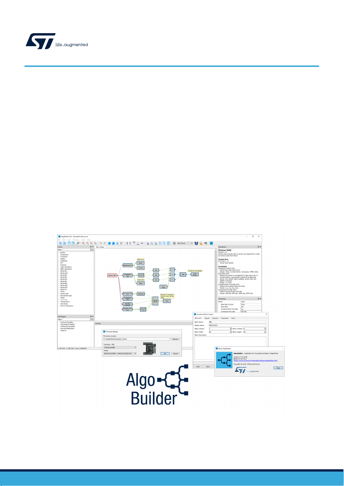
AlgoBuilder is a graphical design application to build and use algorithms.
The software is distributed in two versions:
• AlgoBuilder – standalone AlgoBuilder software;
• AlgoBuilderSuite – all-in-one software package which contains AlgoBuilder and two other software tools, Unico-GUI &
Unicleo GUI that facilitate the programming of sensors for an easy and intuitive experience for the user.
These tools quickly elaborate prototypes of applications for STM32 microcontrollers and MEMS sensors, including already
existing algorithms (i.e. sensor fusion or pedometer), user-defined data processing blocks and additional functionalities.
The application facilitates the process of implementing proof of concept using a graphical interface without writing the code.
AlgoBuilder reuses previously defined blocks, combines multiple functionalities in a single project and visualizes data using
Unicleo-GUI in real time using plot and display.
AlgoBuilder utilizes the STM32 ODE (Open Development Environment) ecosystem which combines hardware like STM32
Nucleo boards (NUCLEO-F401RE or NUCLEO-L476RG), X-NUCLEO-IKS01A2 or X-NUCLEO-IKS01A3 expansion board and
software (STM32 HAL drivers, BSP structure, low and high-level sensor drivers) along with SensorTile.box and STWIN.
UM2373 - Rev 9 - October 2020
For further information contact your local STMicroelectronics sales office.
www.st.com
Page 2

1 Description
1.1 Overview
The main objectives of AlgoBuilder are:
• quick prototyping of applications for STM32 microcontrollers and MEMS sensors which already include
existing algorithms (e.g. sensor fusion or pedometer), user-defined data processing blocks and additional
functionalities
• easier process of implementing proof of concept using graphical interface without writing the code
• reuse of previously defined blocks
• combination of multiple functionalities in a single project
• visualization of data in Unicleo-GUI in real time using plot and display
The key features of the application include:
• Simple graphical design of algorithms (drag and drop, connect, set properties, build, upload)
• Optional multi-level design
• Wide range of function blocks available in libraries, including motion sensor algorithms (e.g. sensor fusion,
gyroscope, magnetometer calibration, pedometer, ...)
• Integrated function blocks for FFT analysis
• Function block creator for custom block creation
• Automatic validation of design rules
• C code generation from the graphical design
• Use of external compilers (STM32CubeIDE, IAR EWARM, Keil µVision®, System Workbench for STM32)
• Possibility to automatically generate MLC settings for compatible iNEMO inertial modules using Unico-GUI
• Generated firmware output displayed through integrated output data monitor or Unicleo-GUI
• Open XML format for function blocks and design storage
• Possibility to send output data to AWS cloud using MQTT protocol
• Support for NUCLEO-F401RE or NUCLEO-L476RG with connected X-NUCLEO-IKS01A2 or X-NUCLEO-
IKS01A3 expansion board, SensorTile STEVAL-STLKT01V1, SensorTile.box STEVAL-MKSBOX1V1 and
STWIN SensorTile STEVAL-STWINKT1
• Network updates with automatic notification of new releases
UM2373
Description
1.2
UM2373 - Rev 9
Prerequisites
The following software and hardware are needed to fully exploit the functions of AlgoBuilder.
• One of the following IDEs:
– STM32CubeIDE 1.0.0 or newer
– IAR-EWARM 8.11.0 or newer
– Keil µVision 5.22 or newer
• Unicleo-GUI
• STM32CubeProgrammer (STM32CubeProg)
• STM32 Virtual COM Port Driver (STSW-STM32102)
• NUCLEO-F401RE or NUCLEO-L476RG with X-NUCLEO-IKS01A2 or X-NUCLEO-IKS01A3 or SensorTile
STEVAL-STLKT01V1 or SensorTile.box STEVAL-MKSBOX1V1 and STWIN SensorTile STEVAL-STWINKT1
page 2/53
Page 3
1.3 Terms and references
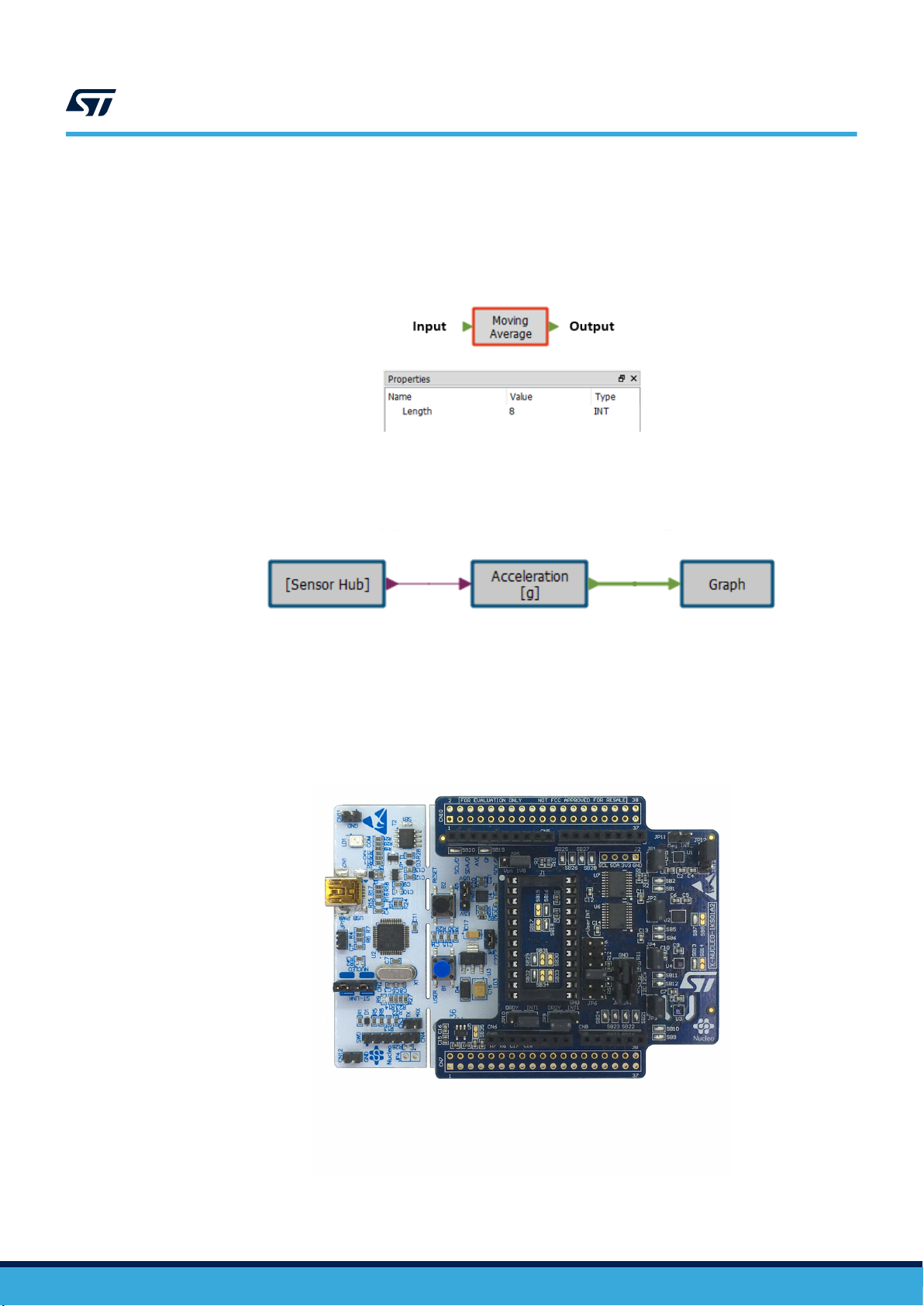
• Function block is a data processing element with one or multiple inputs or outputs. It processes inputs and
generates outputs and can have one or more properties.
• Design is a set of several function blocks connected together.
UM2373
Terms and references
Figure 1. AlgoBuilder function block
Figure 2. AlgoBuilder design
• Node represents the connection between two function blocks.
• Firmware for STM32 microcontroller can be built from the design.
• STM32 Nucleo development board with an STM32 microcontroller used for design testing.
• X-NUCLEO-IKS01A2 motion MEMS and environmental sensor expansion board which embeds
accelerometer, gyroscope, magnetometer, temperature, humidity and pressure sensors.
Figure 3. STM32 Nucleo (NUCLEO-F401RE) plus X-NUCLEO-IKS01A2
UM2373 - Rev 9
page 3/53
Page 4
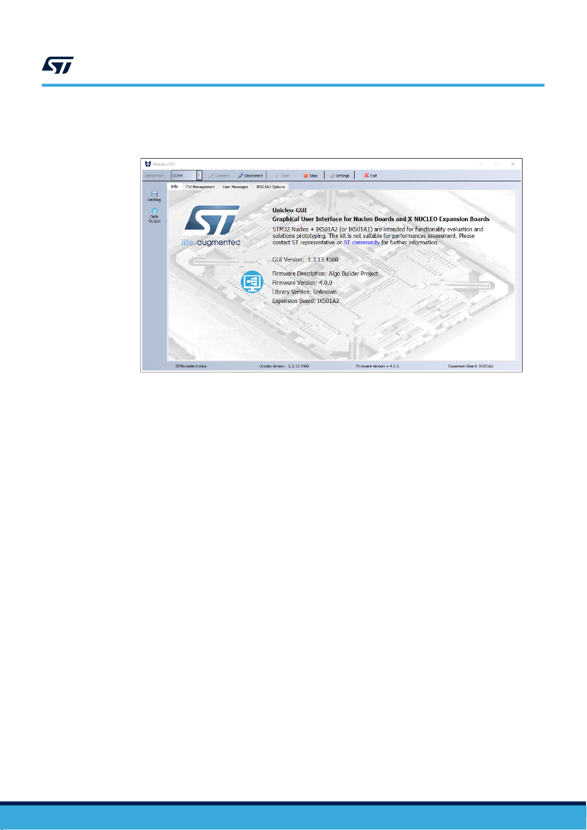
• Unicleo-GUI can be used to display the firmware outputs.
Figure 4. Unicleo-GUI
UM2373
Terms and references
UM2373 - Rev 9
page 4/53
Page 5
1.4 Principle of operation
The workflow starts from the graphical design of the desired functionality by using a simple "drag and drop"
approach.
You can use the predefined function blocks provided in the form of libraries.
You can also create a custom function block. Some function block properties can or must be adjusted in order to
run (in the example, filter coefficients are defined in the filter function block properties). Then, you can
interconnect the compatible function blocks using nodes.
AlgoBuilder automatically checks the compatibility between input and output and allows connecting only terminals
with the same type and dimension.
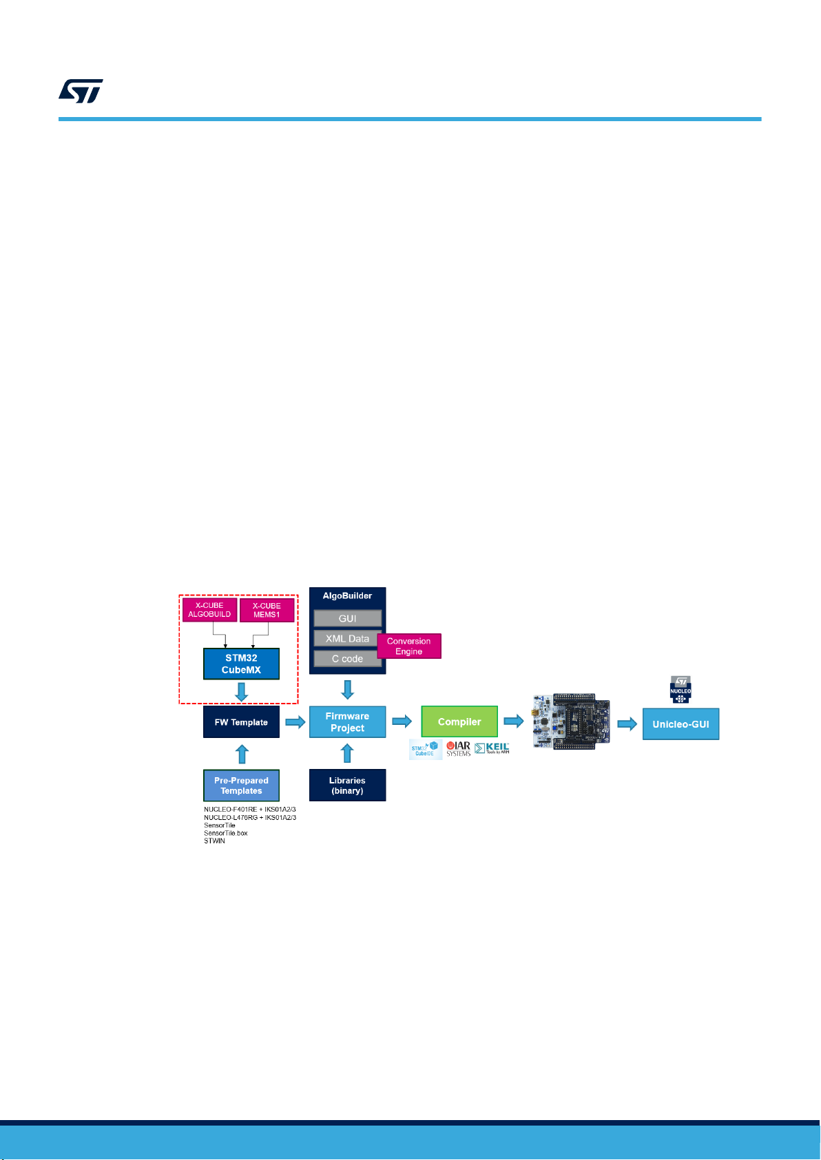
When the design is finished, AlgoBuilder generates the C code from the defined graphical design.
The final firmware project is created from the C code generator combined with pre-prepared firmware templates
and binary libraries.
The project can be compiled using an external compiler tool and the most common Integrated Development
Environments (IDEs) are supported (System Workbench for STM32 with GCC compiler, Keil µVision, IAR
Embedded Workbench).
An STM32 Nucleo board is then programmed by the generated binary file. When the firmware is executed it starts
reading data from the selected sensor, process the data via the algorithm and sends results to Unicleo-GUI
application.
During the graphical design, you can select how to see the results. Graphs, logical analyzer, bar charts, 3D plot,
scatter plot, histogram, teapot, FFT plot and text values are supported.
During the startup, the firmware configures the Unicleo-GUI to display in the desired format.
The graphical designs as well as the libraries are stored as XML files.
UM2373
Principle of operation
Figure 5. AlgoBuilder principle of operation
UM2373 - Rev 9
page 5/53
Page 6
2 Getting started
2.1 Installing the software
The software is distributed in two versions:
• AlgoBuilder – standalone AlgoBuilder software;
• AlgoBuilderSuite – all-in-one software package which contains AlgoBuilder and two other software tools, Unico-
GUI & Unicleo GUI.
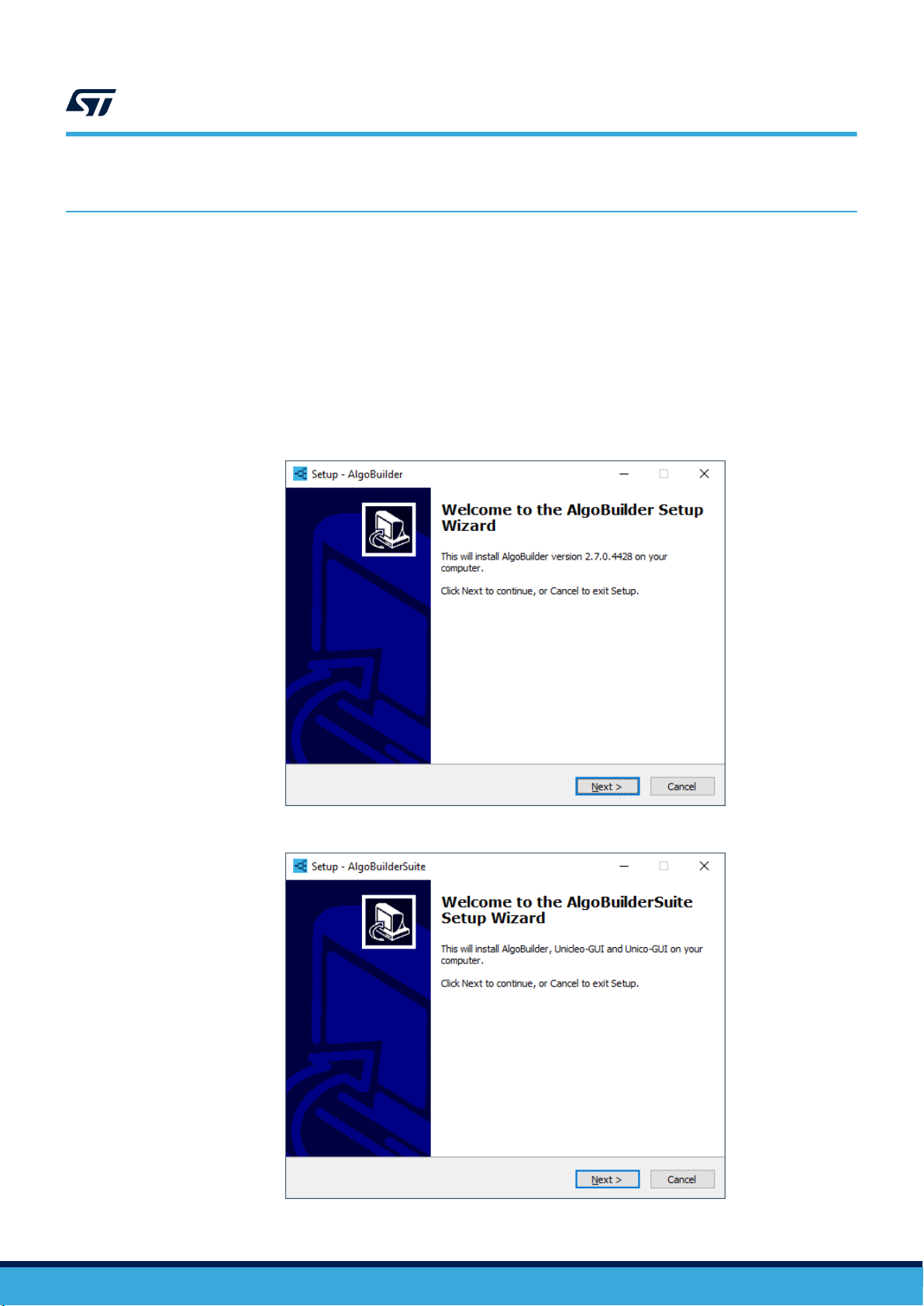
AlgoBuilder software is designed to run in Microsoft® Windows. To install the application, run
Setup_AlgoBuilder.exe or AlgoBuilderSuite.exe, follow the instructions and execute AlgoBuilder once the
installation is complete.
UM2373
Getting started
Figure 6. AlgoBuilder installer
UM2373 - Rev 9
Figure 7. AlgoBuilderSuite installer
page 6/53
Page 7
AlgoBuilderSuite installer contains a certain version of AlgoBuilder, Unicleo-GUI and Unico-GUI. The installer is
able to check simultaneously if a newer version of each individual software is available on st.com and download it
during the installation process.
2.2 Running the software for the first time
The installer may have created a shortcut on your Windows desktop and/or Windows start menu. The AlgoBuilder
can be run by double clicking on the shortcut. If the shortcuts were not created, you can run the AlgoBuilder by
executing AlgoBuilder.exe file which is located in the directory where the application was installed (default location
is C:\Program Files (x86)\STMicroelectronics\AlgoBuilder).
Figure 8. AlgoBuilder icon
UM2373
Running the software for the first time
UM2373 - Rev 9
page 7/53
Page 8
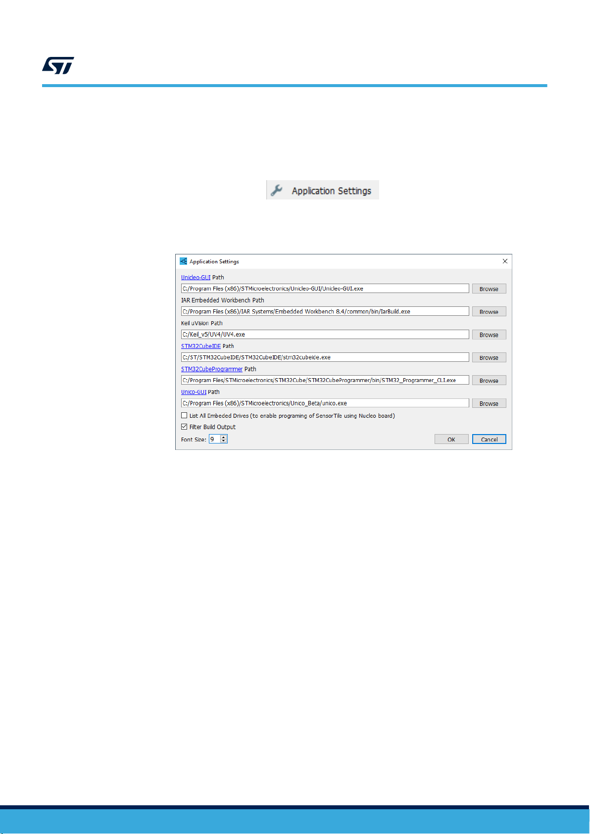
2.3 Application settings
You can adjust the AlgoBuilder configuration in File→Application Settings.
Step 1. Specify the path to Unicleo-GUI.
UM2373
Application settings
Figure 9. Application Settings menu option
Figure 10. Application Settings window
If the path (Unicleo-GUI.exe) is properly set, the Unicleo-GUI can be quickly executed from the toolbar
or the AlgoBuilder menu. If the path is not set, the corresponding icon in the toolbar and item in the
menu are disabled.
Step 2. Specify the path to at least one IDE.
For STM32CubeIDE put the path to stm32cubeide.exe, for System Workbench for STM32 to
eclipsec.exe, for IAR Embedded Workbench to IarBuild.exe and for Keil µVision to UV4.exe.
Step 3. Set up the options related to SensorTile programming.
If you are going to use SensorTile and program it using the integrated ST-LINK V2.1 programmer on an
STM32 NUCLEO board, select List All Embedded Drives.
Step 4. Specify the path to the STM32CubeProgrammer.
If you want to use a standalone ST-LINK programmer or DFU programming mode, specify the path to
the previously installed STM32CubeProgrammer.
Step 5. Set up the application behavior.
If Filter Build Output is enabled, AlgoBuilder automatically filters outputs from the external compiler
and makes them more readable in the console.
The font size can be adjusted as well, for better readability on high-resolution monitors.
UM2373 - Rev 9
page 8/53
Page 9
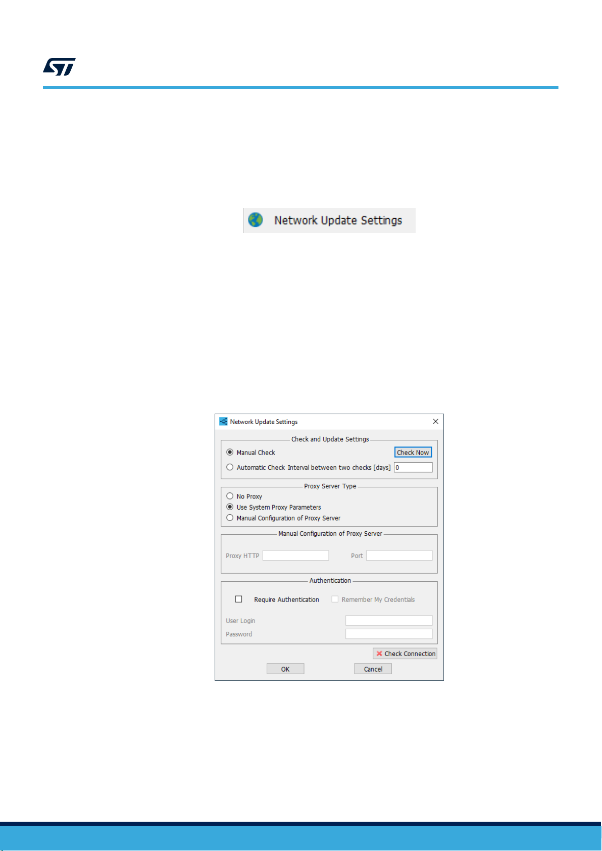
2.4 Network update settings
The application is able to check and notify if a new version is available. You can then decide whether to download
and install the new version.
Some functional network parameters have to be properly set in Network Update Settings in the File menu.
Figure 11. Network Update Settings menu option
The setting dialog is divided in different sections:
1. In the first section you can choose between manual and automatic check. In the latter, you can adjust the
periodicity. If an interval of zero days is set, a check for updates is performed at every application start. To
run an immediate check for updates, click on Check Now.
2. The second section contains options for proxy server type settings.
Tip: When you select Use System Proxy Parameters, it is usually necessary to open a web browser to run
all security scripts before running a check for updates.
3. The third section contains the proxy manual configuration field where the proxy HTTP name and port
number can be entered.
4. The last section contains the authentication credential fields (if required)
The Check Connection button can be used to check if the update server is accessible.
UM2373
Network update settings
Figure 12. Network Update Settings window
UM2373 - Rev 9
page 9/53
Page 10
3 Using AlgoBuilder
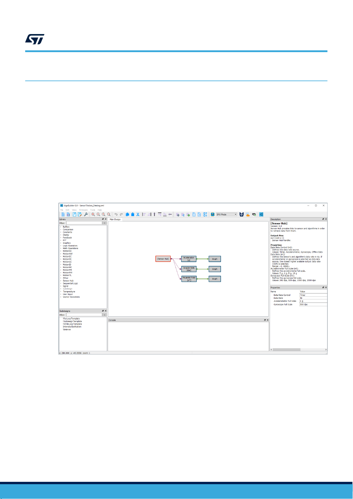
The AlgoBuilder main window contains:
• a central Workspace where the algorithm is designed using function blocks
• a Library dock with a list of available libraries and their function blocks which can be dragged and dropped
to the workspace window
• a Subdesigns dock with a list of available subdesigns and subdesign templates
• a Description dock which displays information about the selected component (function block, connection,
etc.)
• a Properties dock which displays all available properties of the selected function block
• a Console dock which displays messages from the AlgoBuilder or an external compiler
The AlgoBuilder application has a standard menu and a toolbar to speed up access to frequently used functions.
Note: You can change the position of all docks and the toolbar. Docks can be opened and closed in the View
menu.
UM2373
Using AlgoBuilder
Figure 13. AlgoBuilder main window
UM2373 - Rev 9
page 10/53
Page 11

3.1 Workspace
The developed algorithm design is created in the workspace area.
Step 1. Place the necessary function blocks on the workspace
Note: Function blocks can be simply dragged from the library dock and dropped in the workspace.
Step 2. Set their properties
Step 3. Connect them by clicking and holding the mouse left button on the output you want to connect and
move the cursor to the input where the connection should be made. The connection can be created
also in the opposite way from input to output.
Note: You can connect only inputs and outputs of the same type and size. If you try to connect different
types or sizes, the console displays an error message.
You can change the number of inputs for some function blocks (e.g. MUX, Sum, And, Or...).
Step 4. Use Delete to remove any component, Cut, Copy and Paste for any part of the design through the
Edit menu, the Toolbar or the shortcut.
Step 5. Align the function blocks to the right, left, top or bottom.
The last selected function block determines the final position.
Step 6. Use Do and Undo to go back and forward in the performed operations in the workspace.
UM2373
Workspace
Step 7. To Zoom In or Zoom Out use Ctrl and the mouse wheel or the appropriate function in View menu or in
Toolbar.
Step 8. Select Fit All to fit the whole design on the screen.
Step 9. Select Zoom 1:1 to set zoom factor to 1.
Step 10. Right click and hold on the workspace area to explore the content of the design.
3.2
Library dock
The Library dock gives you access to all the available libraries and function blocks located in a particular library.
AlgoBuilder scans [Install path]/Library/ and the user's home directory \STMicroelectronics\AlgoBuilder\Library
during startup and loads all valid libraries located there.
The Graphics library is not stored in an xml file but it is automatically added by AlgoBuilder.
3.3 Subdesigns dock
The Subdesigns dock gives you access to all the available subdesigns.
AlgoBuilder scans [Install path]/Subdesigns/ and the user's home directory \STMicroelectronics\AlgoBuilder
\Subdesigns during startup and loads all valid subdesigns located there. The subdesign templates are located in
the [Install path]/Subdesigns/ directory.
3.4 Description dock
The Description dock provides information about the component selected in the Workspace or in the Library
dock.
If you select a function block, the following information is shown:
• Name
• Version
• Description of the function block functionality
• Type, size and functionality of all inputs
• Type, size and functionality of all outputs
• Description of all function block properties
UM2373 - Rev 9
page 11/53
Page 12

3.5 Properties dock
If a function block has a property or properties, they are displayed in the Properties dock.
Each property has name, value and type fields.
The values can be modified.
The AlgoBuilder automatically checks if the value is valid and does not allow setting an invalid one (for example, a
value out of an available range).
For the STRING type, the % character is forbidden and is automatically deleted.
UM2373
Properties dock
UM2373 - Rev 9
page 12/53
Page 13
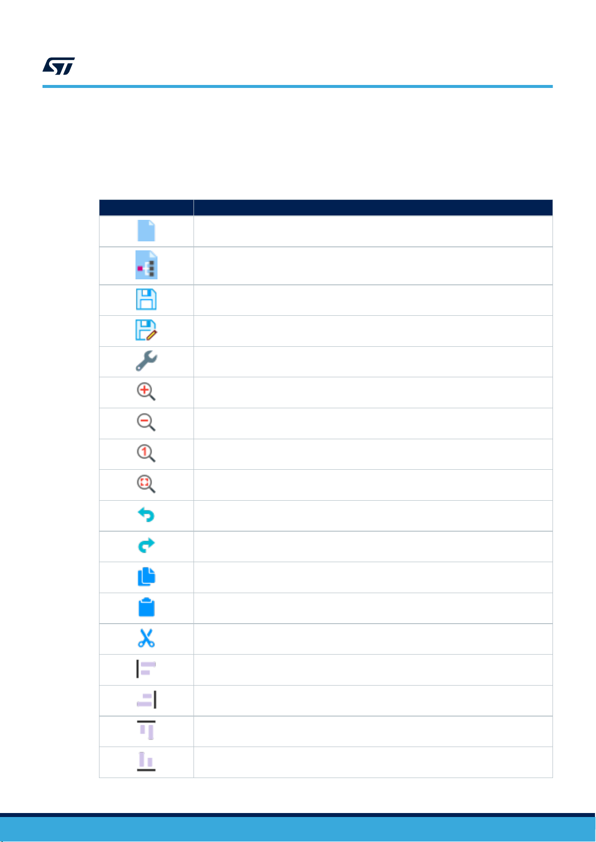
3.6 Toolbar
The Toolbar provides quick access to the most commonly used functions. The position of the toolbar and the
order of the function can be adjusted.
Toolbar icon Function
UM2373
Toolbar
Table 1. AlgoBuilder toolbar default functions
Creates new design
Open existing design
Save design (subdesign)
Save design (subdesign) as different file
Open Application Settings window
Zoom In
Zoom Out
Set zoom to 1:1 ratio
Fit all design into screen
Undo
Redo
Copy
Paste
Cut
UM2373 - Rev 9
Align to the left
Align to the right
Align to the top
Align to the bottom
page 13/53
Page 14
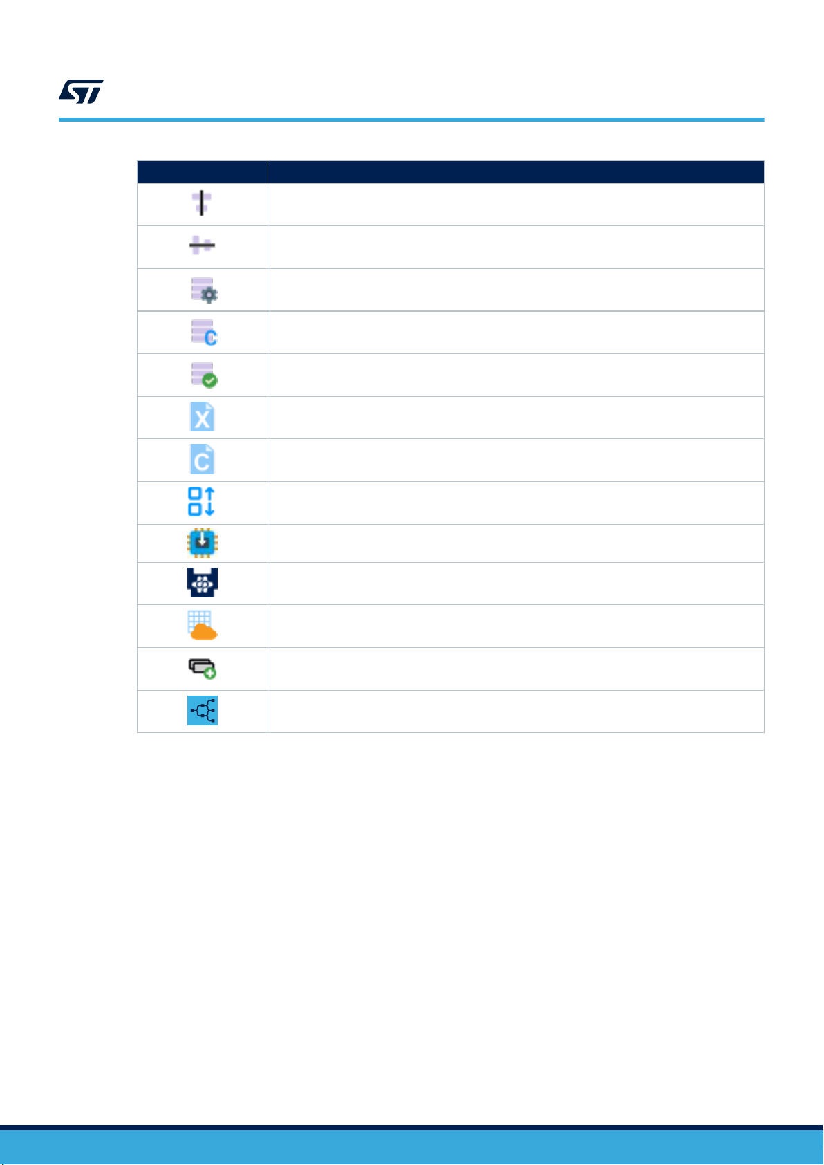
Toolbar icon Function
Align to center horizontally
Align to center vertically
Open Firmware Settings window
Generates C Code from the graphical design
Build firmware / Validate subdesign
Show the design xml source file in the default text editor
Show C Code in the default text editor
UM2373
Toolbar
Arrange Toolbox Buttons
Program Target
Run Unicleo-GUI application
Input Data & Output Data Monitor & AWS Connectivity
Open Function Block Creator
Open About window
UM2373 - Rev 9
page 14/53
Page 15
4 Data types
AlgoBuilder works with four data types:
• FLOAT represents real numbers and is used for floating-point arithmetic (for example, in the acceleration
function block output). In C code, the representation float variable is used. The size is 4 bytes.
• INT represents integer numbers (for example, in the counter function block). In C code, int32_t variable is
used. The size is 4 bytes.
• VARIANT is used for inputs of a set of function blocks; the variant changes its type on the basis of the type
of output connected to this input (for example, the variant type is used for inputs of comparison function
blocks).
• VOID is used exclusively for the connection between Sensor Hub and its data outputs. This type cannot be
visualized.
Each input or output is characterized by its type and size: the thickness of the connection line indicates the size of
input and output and color of the connection line indicated the type.
The size value can be changed in the properties.
Important: Only input and output with the exact same type and size can be connected together. The only
exception is the VARIANT input which gets the type of connected output.
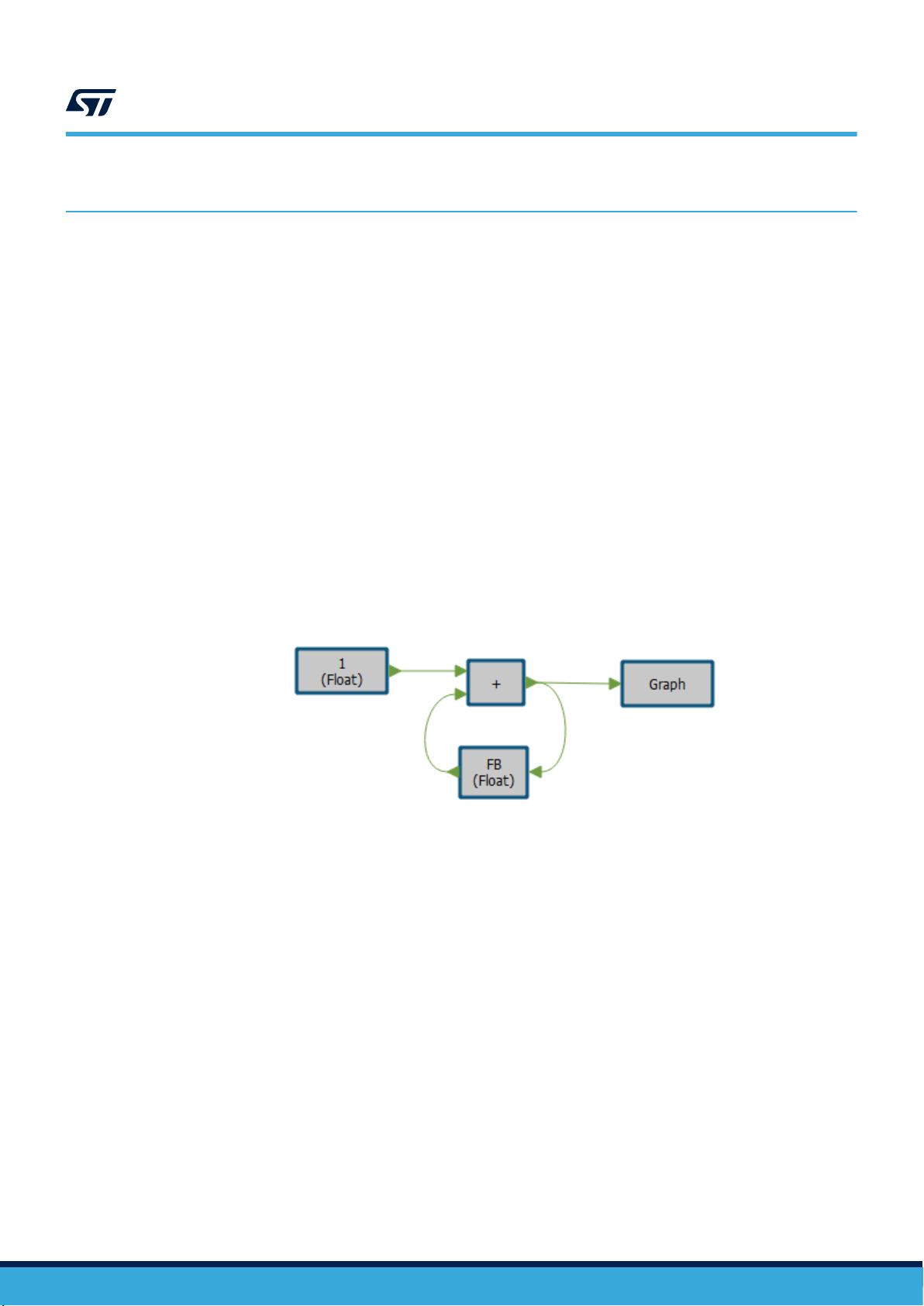
It is not possible to connect the input and output of the same function block. If this is desired, the Feedback
function block for the particular data type needs to be used. The Feedback function block has an Init value, which
defines the output value of the block for the first run.
UM2373
Data types
Figure 14. Using the Feedback function block
UM2373 - Rev 9
page 15/53
Page 16
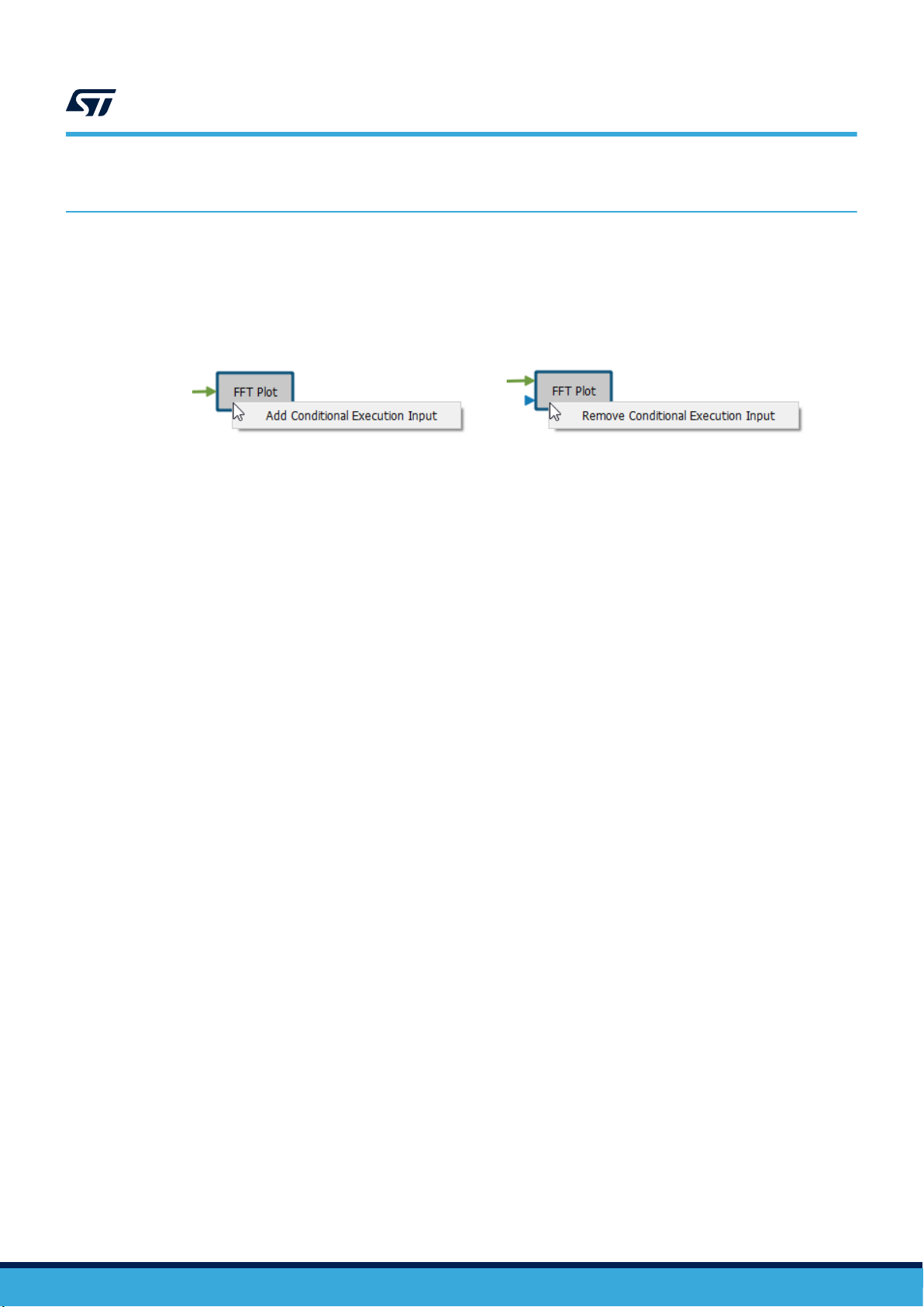
5 Conditional Execution
In some cases, it is needed to execute the function block operation only if a certain condition is valid. For this
case it is possible to add Conditional Execution Input to the selected function block. This input then defines if
the function block code will be executed or not. This is represented as an if statement in the generated C code. To
add or remove the conditional execution input, click on the function block using the right mouse button.
UM2373
Conditional Execution
Figure 15. Conditional Execution
UM2373 - Rev 9
page 16/53
Page 17
6 Libraries
The following libraries are available for a fresh AlgoBuilder installation.
Library Content
Buffers Function blocks for operations with data buffers
Comparison Function blocks for two value comparison (e.g. >, <, =, etc.)
Constants Function blocks for constant definition
Display Function blocks for data visualization in Unicleo-GUI application
FFT Function blocks related to FFT analysis
Graphics Text note to annotate the design
Logic Operators Function blocks for logic operations (e.g. And, Or, …, etc.)
Math Operations Function blocks for various mathematical operations (e.g. +, -, /, etc.)
Other Auxiliary function blocks (e.g. mux, demux, type conversion, etc.)
Sensor Hub
Sequential Logic Function block for sequential logic (flip flops)
Signal Function blocks for signal processing (e.g. filters, etc.)
Subdesign Input and output terminals for subdesigns
Temperature Function blocks for temperature units conversion
User Input
Vector Operations Function blocks for vector operation (e.g. calculate magnitude, etc.)
UM2373
Libraries
Table 2. AlgoBuilder installation libraries
Main Sensor Hub function block, which provides access to the sensors and pre-build algorithm and function blocks for
data acquisitions from connected sensors.
Function blocks which allow user to send arbitrary data to the running firmware at real-time through Unicleo-GUI
application
Already prepared algorithms in binary form can be also integrated in the user design.
Table 3. AlgoBuilder supported libraries
Library
MotionAC Accelerometer calibration algorithm
MotionAW Activity recognition algorithm for wrist-worn devices
MotionEC eCompass algorithm
MotionFX Sensor fusion algorithm
MotionGC Real-time gyroscope calibration algorithm
MotionID Motion intensity detection algorithm
MotionMC Real-time magnetometer calibration algorithm
MotionPM Pedometer algorithm for mobile devices
MotionPW Pedometer algorithm for wrist-worn devices
MotionTL Tilt sensing algorithm
Functionality
Binary libraries are included in the firmware only if at least one function block is used in the design. This reduces
occupied FLASH and RAM memory.
UM2373 - Rev 9
page 17/53
Page 18

7 Creating your first design
As a first example, you can create a design to read acceleration from the accelerometer sensor at a selected data
rate and send data to Unicleo-GUI to be visualized in a time chart.
Step 1. Start with blank design by clicking on the icon (Create new design) in the toolbar or the File menu.
The Firmware Settings window is opened automatically or you can open it by clicking on the icon
(Firmware settings) in the toolbar or Firmware menu.
Step 2. Set the path to the directory where the output firmware is located, the IDE to be used to build the
firmware and the target to be used for testing. It is important to select the correct target.
Figure 16. AlgoBuilder Firmware Settings window
UM2373
Creating your first design
Step 3. Drag the [Sensor Hub] function block from the Sensor Hub library and drop it into the workspace.
Important: Each design must start with the Sensor Hub function block, which provides access to the
sensors and pre-build algorithm.
Figure 17. Sensor Hub function block
Step 4. Adjust Sensor Hub properties, select Timer as the source for Data Rate Control, set the Data Rate to
50 Hz and Accelerometer Full Scale to 2 g.
Figure 18. Sensor Hub properties
Step 5. Add Acceleration [g] function block from the Sensor Hub library and Graph function block from the
Display library to the workspace.
UM2373 - Rev 9
Figure 19. Sensor Hub, Acceleration[g], Graph function blocks
page 18/53
Page 19
UM2373
Creating your first design
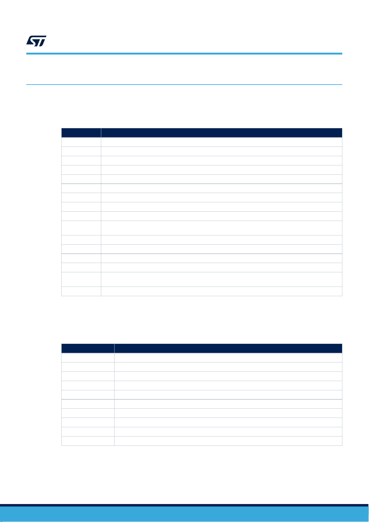
Step 6. Adjust Graph properties.
The Number of Curves in Graph defines the size of its input. The value needs to be changed to 3 to
match the Acceleration [g] output size. The Graph, Waveform and Unit names can be also changed.
Figure 20. Graph properties
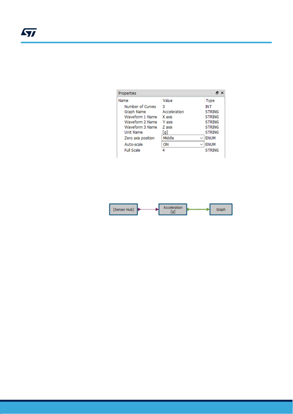
Step 7. Connect the function blocks by clicking on [Sensor Hub] output, holding and moving your mouse to the
input of the Acceleration [g] block.
Step 8. Repeat the previous step to connect Acceleration [g] to Graph block.
Figure 21. Sensor Hub, Acceleration[g], Graph function blocks
Your design is ready and you can generate C code from it.
UM2373 - Rev 9
page 19/53
Page 20

Step 9. Click on the icon (Generate C Code) in the toolbar or Firmware menu.
This function copies the firmware template into the previously selected file and creates the
algo_builder.c file which is C code representation of the graphical design. If the operation is successful,
the message “Code generation finished successfully” appears in the console. You can check the
generated C code by clicking on the icon (Show C Code) in the toolbar or Firmware menu.
Figure 22. Generated code in algo_builder.c file
UM2373
Creating your first design
Note: In case the firmware template in the target directory is accidentally broken or deleted you can
invoke re-initialization of the firmware template by clicking on the icon (Re-initialize Firmware) in
the Firmware menu.
Step 10.
Click on the icon (Build Firmware) to call the external IDE to build the firmware project and
generate a binary file for the STM32 microcontroller.
The console shows an output from the compiler. Once the compilation finishes, a “Build Process
Finished” message appears. If there is no error message from the compiler, the firmware is ready to be
programmed in the STM32 Nucleo board.
Figure 23. System Workbench for STM32 output
Note: Only files which were changed are compiled during the firmware building process. To use the
external tool to recompile all files, select the icon (Rebuild Firmware) in the Firmware menu.
Step 11. Save the design by clicking on the icon (Save Design) in the toolbar of the File menu.
UM2373 - Rev 9
page 20/53
Page 21

8 Programming the target
8.1 STM32 Nucleo board
AlgoBuilder automatically scans for connected STM32 Nucleo boards.
The list of connected STM32 Nucleo boards is available in the toolbar next to the "Program Target" icon.
If the firmware is successfully built and an STM32 Nucleo board is selected, you can program the board by
pressing the button (Program Target).
Figure 24. Program target icon and selection box
UM2373
Programming the target
8.2
SensorTile
SensorTile does not have a built-in programmer. To program the board, connect an external ST-LINK programmer
to the SWD connector on the cradle using the 5-pin flat cable which is provided in the SensorTile Kit package.
The easiest way to obtain an ST-LINK device is to get an STM32 Nucleo board which bundles an ST-LINK V2.1
debugger and programmer. Both CN2 jumpers on the STM32 Nucleo board have to be removed to program
SensorTile.
To see all STM32 Nucleo boards in the AlgoBuilder selection box select List All Embedded Drives in the
AlgoBuilder settings. Then you can select the STM32 Nucleo board which you are going to use to program
SensorTile and press the program button .
If you want to use the standalone ST-LINK programmer, STM32CubeProgrammer must be installed on the PC
and the path to this tool set in the AlgoBuilder application settings. If this is done, the ST-LINK programmer will be
available in the list of targets in the toolbar.
Figure 25. STM32 Nucleo board, SensorTile cradle SWD connectors
UM2373 - Rev 9
page 21/53
Page 22
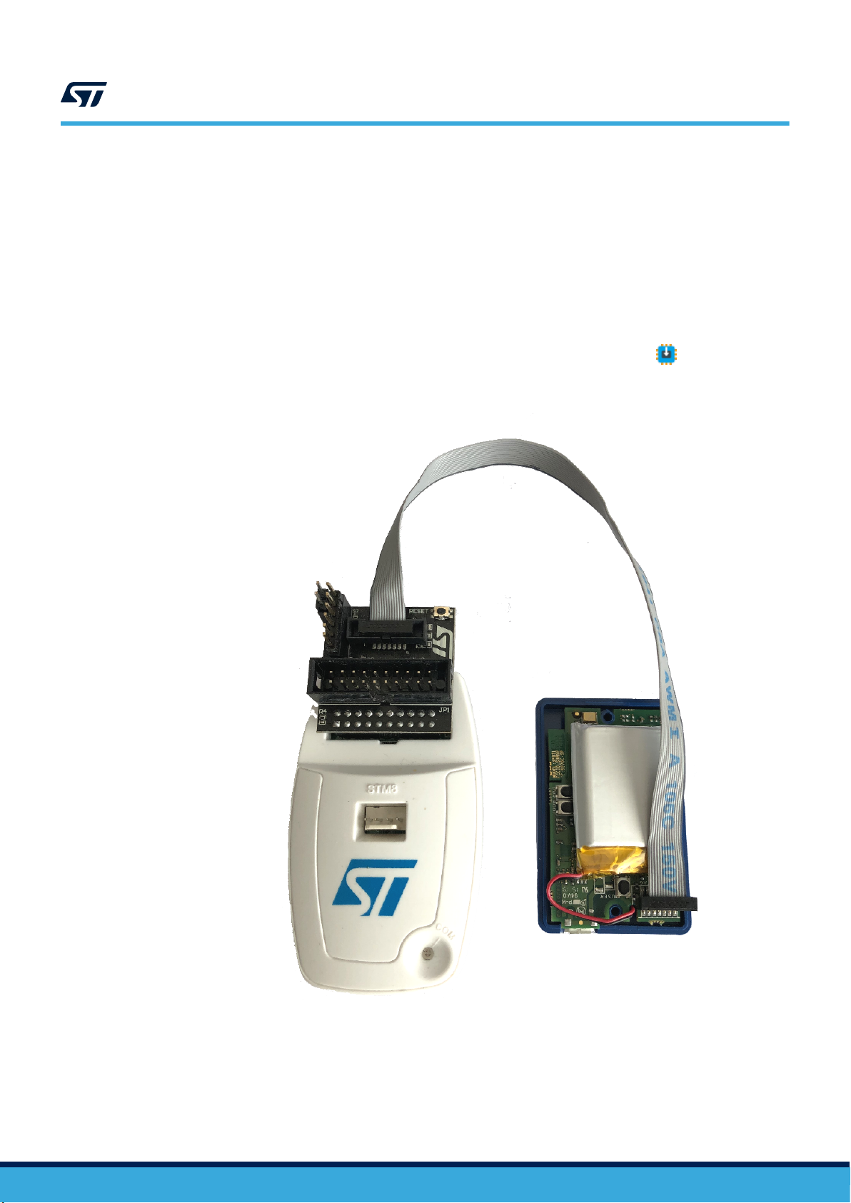
8.3 SensorTile.box or STWIN
SensorTile.box and STWIN do not have a built-in programmer. There are two options for programming the device:
1. Use ST-Link programmer
To program the board, connect an external ST-LINK programmer to the 14-pin JTAG connector on the
SensorTile.box or STWIN.
A 20-pin (2.54 mm pitch) to 14-pin (1.27 mm pitch) adapter is needed.
STM32CubeProgrammer must be installed on the PC and the path to this tool set in the AlgoBuilder
application settings. If this is done, the ST-LINK programmer will be available in the list of targets in the
toolbar.
Then you can program the SensorTile.box or STWIN by pressing the program button .
Figure 26. STM32ST-Link programmer and SensorTile.box interconnection
UM2373
SensorTile.box or STWIN
UM2373 - Rev 9
page 22/53
Page 23
SensorTile.box or STWIN
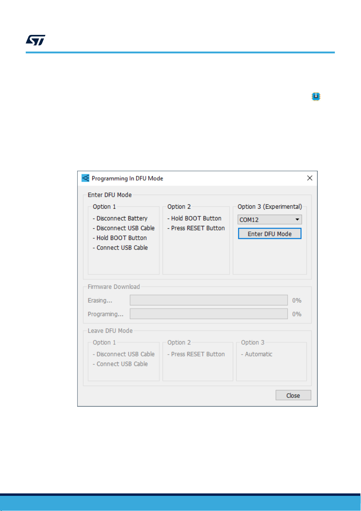
2. Use DFU (Device Firmware Upgrade)
DFU mode allows programming the device without requiring a programmer. DFU mode is available only if
SensorTile.box or STWIN is selected as Target in Firmware Settings. If SensorTile.box or STWIN is
selected, DFU mode is available in the list of targets in the toolbar. By pressing the program button , a
dedicated window for DFU is opened. There are three options for switching the device to DFU mode. The
procedures are described in the window. If AlgoBuilder firmware is already in the device, the DFU can be
entered by a single click on Enter DFU mode in Option 3. After the device is switched to DFU mode, the
memory is automatically erased and programmed by new firmware.
Exiting DFU mode is done either automatically or can be done manually (Option 1 or 2).
For DFU mode, STM32CubeProgrammer must be installed on the PC and the path to this tool set in the
AlgoBuilder application settings.
Figure 27. Programming SensorTile.box or STWIN in DFU mode
UM2373
UM2373 - Rev 9
page 23/53
Page 24
9 Using Unicleo-GUI
Unicleo-GUI can be used to check the functionality of the firmware. You can visualize data coming from the
firmware and send data from Unicleo-GUI to the running firmware.
9.1 Data visualization
There are eight types of data visualization:
• Bar Graph
• 3D Teapot Model
• Graph
• Histogram
• Logic Analyzer
• 3D Plot
• Scatter Plot
• Text Value
To send data to Unicleo-GUI, the appropriate function block needs to be added to the design.
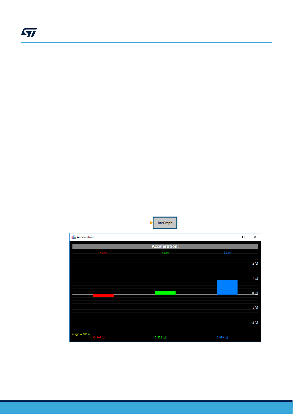
• Add the Bar function block from the Display library to your design to display data as a bar graph. A bar
graph is suitable for a quick check of an actual value without needing to see the history. This graph works
with any floating or integer value and each of them can have up to 6 bars. In the properties field, you can set
the name of the graph, of each bar, unit on the Y-axis, position of the 0 on Y axis, full scale and enable or
disable auto-scale.
UM2373
Using Unicleo-GUI
Figure 28. Bar function block and example of data visualization in Unicleo-GUI
UM2373 - Rev 9
page 24/53
Page 25
UM2373
Data visualization
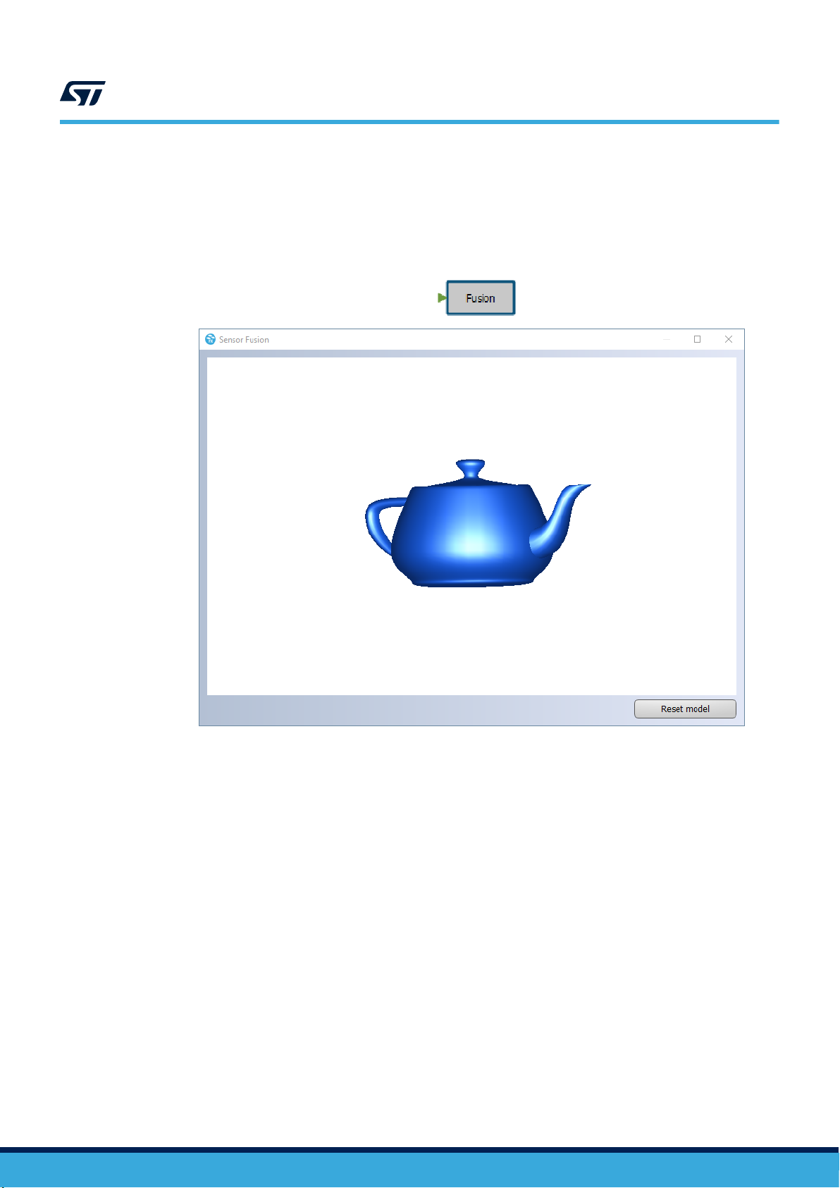
• Add the Fusion function block from the Display library to your design to display quaternion data as the
teapot 3D model.
The 3D Teapot Model is usually used to check device orientation in 3D space. This graph requires
quaternions which can be obtained for example from the sensor fusion (MotionFX) algorithm.
Figure 29. Fusion function block and example of data visualization in Unicleo-GUI
UM2373 - Rev 9
page 25/53
Page 26

UM2373
Data visualization
• Add the Graph function block from the Display library to your design to display data as a time graph.
This graph works with any floating or integer value and each of them can have up to 6 waveforms. In the
properties field, you can set the name of the graph, of each waveform, unit on the Y-axis, position of the 0 on
Y axis, full scale and enable or disable auto-scale.
Figure 30. Graph function block and example of data visualization in Unicleo-GUI
• Add the Histogram function block from the Display library to your design to display the data distribution
chart.
The histogram can be used to see the distribution of the selected value. In the properties field, you can set
the name of the graph, number of intervals, zero axis position, full scale and enable or disable auto-scale.
Figure 31. Histogram function block and example of data visualization in Unicleo-GUI
UM2373 - Rev 9
page 26/53
Page 27

UM2373
Data visualization
• Add the Logic Analyzer function block from the Display library to display logic signals which can have
values of only 0 or 1.
The logic analyzer can have up to 8 channels. In properties, you can change the name of each channel.
Figure 32. Logic Analyzer function block and example of data visualization in Unicleo-GUI
UM2373 - Rev 9
page 27/53
Page 28
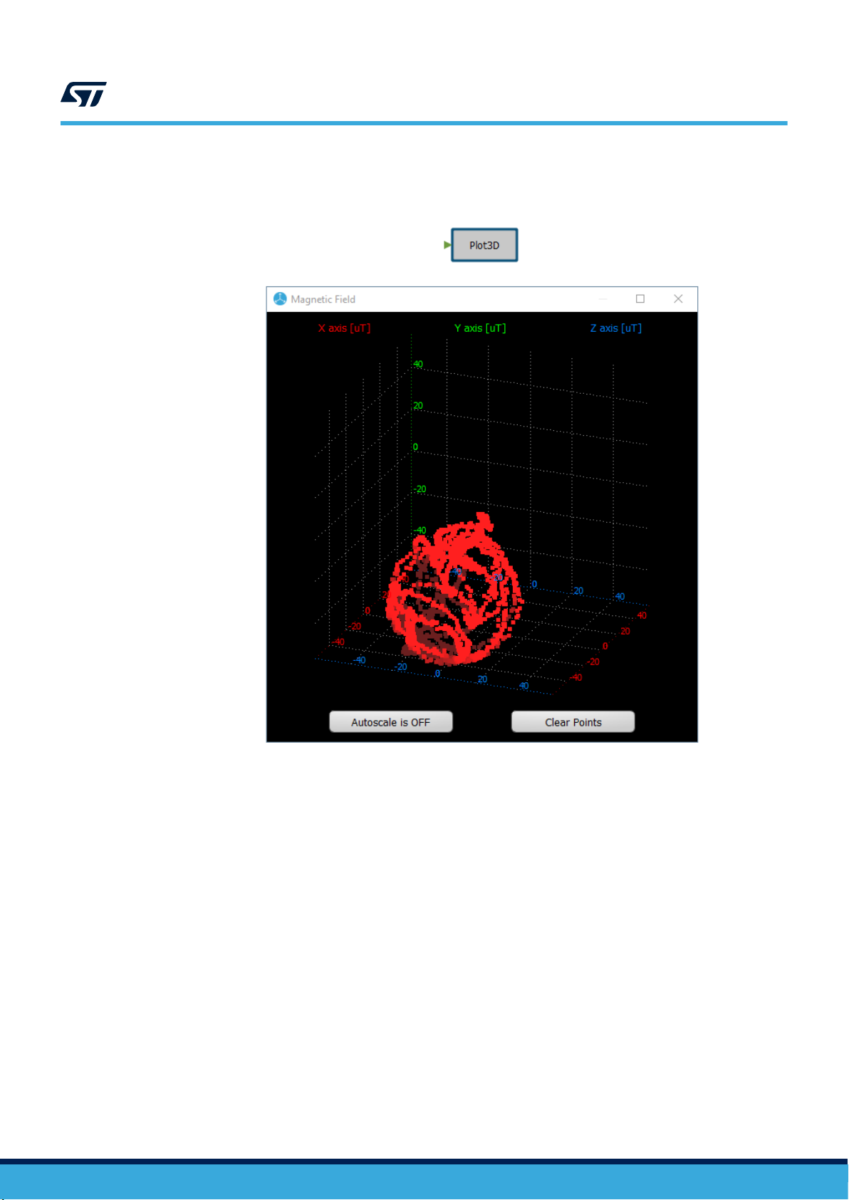
• Add the Plot3D function block from the Display library to display X,Y,Z data in the 3D chart.
Figure 33. 3D Plot function block and example of data visualization in Unicleo-GUI
UM2373
Data visualization
UM2373 - Rev 9
page 28/53
Page 29

UM2373
Data visualization
• Add the Scatter Plot function block from the Display library to display X, Y, Z data in the 2D X-Y, X-Z, Y-Z
chart.
Figure 34. Scatter Plot function block and example of data visualization in Unicleo-GUI
UM2373 - Rev 9
page 29/53
Page 30

Data visualization
• Add the Value function blocks from the Display library to display the exact float or integer value
Each function block can display up to 8 values. In properties, you can change the name of the value and unit
for each item.
Figure 35. Value function block and example of data visualization in Unicleo-GUI
UM2373
UM2373 - Rev 9
page 30/53
Page 31

9.2 Data input
Three types of data can be sent from Unicleo-GUI to running firmware: Binary, Integer and Float.
Add the Input Value function block (with appropriate type) from the User Input library to your design.
Each Input Value function block can represent up to 4 values. In properties, you can set the name of each value
and default value. The Input Value function block output size is defined by the Number of Values property.
UM2373
Data input
Figure 36. Input Value function blocks
Figure 37. Input Values in Unicleo-GUI
UM2373 - Rev 9
page 31/53
Page 32

9.3 Set Toolbox Buttons order
The toolbox buttons in Unicleo-GUI might become disorganized when many Display and User input function
UM2373
Set Toolbox Buttons order
blocks are used in the AlgoBuilder design. These toolbox buttons can be arranged by clicking on the icon
Toolbox Buttons Order) in the toolbar or the Firmware menu.
Figure 38. Set Toolbox Buttons Order window
(Set
UM2373 - Rev 9
page 32/53
Page 33

10 FFT (Fast Fourier Transform)
AlgoBuilder offers also a function block for frequency analysis of the sensor’s output signal using FFT (Fast
Fourier Transform). Fourier analysis converts a signal from the time domain to a representation in the frequency
domain.
Figure 39. FFT function block
UM2373
FFT (Fast Fourier Transform)
The FFT function block offers frequency analysis from 32, 64, 128, 256, 512 and 1024 samples. It is also possible
to enable window usage to eliminate spectrum leakage. Hanning, Hamming, and Flat Top windows can be used.
Output from the FFT function block can be connected to the FFT plot function block, which will send the results to
Unicleo-GUI. Unicleo-GUI then displays the data as a frequency spectrum. To send data to Unicleo-GUI only
when the FFT calculation is finished, conditional execution input must be added to the FFT plot and connected to
the FFT function block.
Figure 40. FFT and FFT Plot connections
UM2373 - Rev 9
page 33/53
Page 34

Figure 41. Frequency spectrum in Unicleo-GUI
UM2373
FFT (Fast Fourier Transform)
Note: To get the correct frequency values, it is necessary to select the sensor whose data are analyzed in the
data rate control device in the Sensor Hub. Real sensor ODR (output data rate) is measured during firmware
initialization.
UM2373 - Rev 9
page 34/53
Page 35

Finite State Machine (FSM) and Machine Learning Core (MLC)
11 Finite State Machine (FSM) and Machine Learning Core (MLC)
AlgoBuilder also allows using outputs from the Finite State Machine and/or Machine Learning Core in the design.
The FSM / MLC function block is available in the Sensor Hub library.
Figure 42. Example of design with FSM / MLC
The configuration of the FSM and MLC is stored in the UCF file. The UCF file can be created in Unico-GUI
software. Unico-GUI can be directly opened from AlgoBuilder by pressing the Generate UCF file button in the
FSM / MLC function block properties.
It is mandatory to specify the number of used FSM and MLC outputs in the UCF file. The size of the FSM / MLC
output vector is adjusted accordingly.
UM2373
Figure 43. FSM / MLC function block properties
Warnings:
The UCF file also usually contains settings of the sensor full scale (FS) and output data rate (ODR). This setting
might be different than the settings required by the Sensor Hub. The firmware generated by AlgoBuilder contains
a function to check if the FS and ODR set by the UCF file is compatible with the Sensor Hub settings. If not, an
error message is generated.
The interrupt pin INT1 is usually configured by Unico-GUI in which case it is not possible to use the accelerometer
or gyroscope as Data Rate Control in the Sensor Hub.
The FSM / MLC function block can be used only with sensors which are equipped with this functionality.
UM2373 - Rev 9
page 35/53
Page 36
12 Creating your own function block
A function block is defined as XML records in an XML file.
Each XML file represents an AlgoBuilder library, which may contain one or more function blocks.
A library has the following structure, where each function block is described inside the <Block></Block> tags.
<?xml version="1.0" encoding="UTF-8"?>
<Library>
<Version>1.0</Version>
<Name>Comparison</Name>
<Block>
</Block>
</Library>
Each function block must have the XML tags listed below.
Table 4. Function block XML tags
Tag Description
<Name></Name>
<DisplayName></
DisplayName>
<Version></Version>
<Description></
Description>
<Width></Width>
<Height></Height>
<X></X>
<Y></Y>
<Instances></Instances>
<Inputs></Inputs>
<Input></Input>
<Type></Type>
<Size></Size>
<Name></Name>
<Description></
Description>
<Outputs></Outputs>
<Output></Output>
<Type></Type>
<Size></Size>
<Name></Name>
<Description></
Description>
<Properties></Properties>
Name of the function block displayed in the list of the Library dock.
Text displayed in the function block rectangle when placed in the workspace. Two hash signs (##)
can be used to break the text in a new line.
Version of the function block.
Description of the overall function block functionality displayed in the Description dock.
Width of the function block rectangle.
Height of the function block rectangle.
X position of the function block: it must be 0.
Y position of the function block: it must be 0.
The maximum number of a particular function block in one design. Put 0 value for the unlimited
number of instances.
List of all inputs.
Input definition with <Type>, <Size>, <Name>, <Description> tags.
Data type of the particular input. The following types can be used: INT, FLOAT, VARIANT
Data size of the particular input.
Name of the particular input.
Description of the particular input.
List of all outputs.
Output definition with <Type>, <Size>, <Name>, <Description> tags.
Data type of the particular output. The following types can be used: INT, FLOAT, VARIANT
Data size of the particular output.
Name of the particular output.
Description of the particular output.
List of all properties.
UM2373
Creating your own function block
UM2373 - Rev 9
page 36/53
Page 37
Tag Description
<Property></Property>
<Type></Type>
<Name></Name>
<Value></Value>
<Description></
Description>
<Memory></Memory>
<Item></Item>
<Type></Type>
<Size></Size>
<Name></Name>
<Command></Command>
<Line></Line>
<Function></Function>
<Line></Line>
<InitCode></InitCode>
UM2373
Creating your own function block
Property definition with <Type>, <Name>, <Value>, <Description> tags.
Data type of the particular property. The following types can be used: INT, FLOAT, STRING
Name of the particular property.
Default value of the particular property.
Description of the particular property.
List of all memory items.
Memory item definition.
Data type of the particular memory item. The following types can be used: INT, FLOAT
Data size of the particular memory item.
Name of the particular memory item.
C language commands representing the function block. Each command must be placed on a new
line between <Line></Line> tags. The value of any input, output or property can be used in the
commands. For this put % before and after the name of the input, output or property.
It is possible to define a complete function to be used in the <Command> tag. Each command must
be placed on a new line between <Line></Line> tags.
C language commands executed once, during firmware initialization.
UM2373 - Rev 9
page 37/53
Page 38
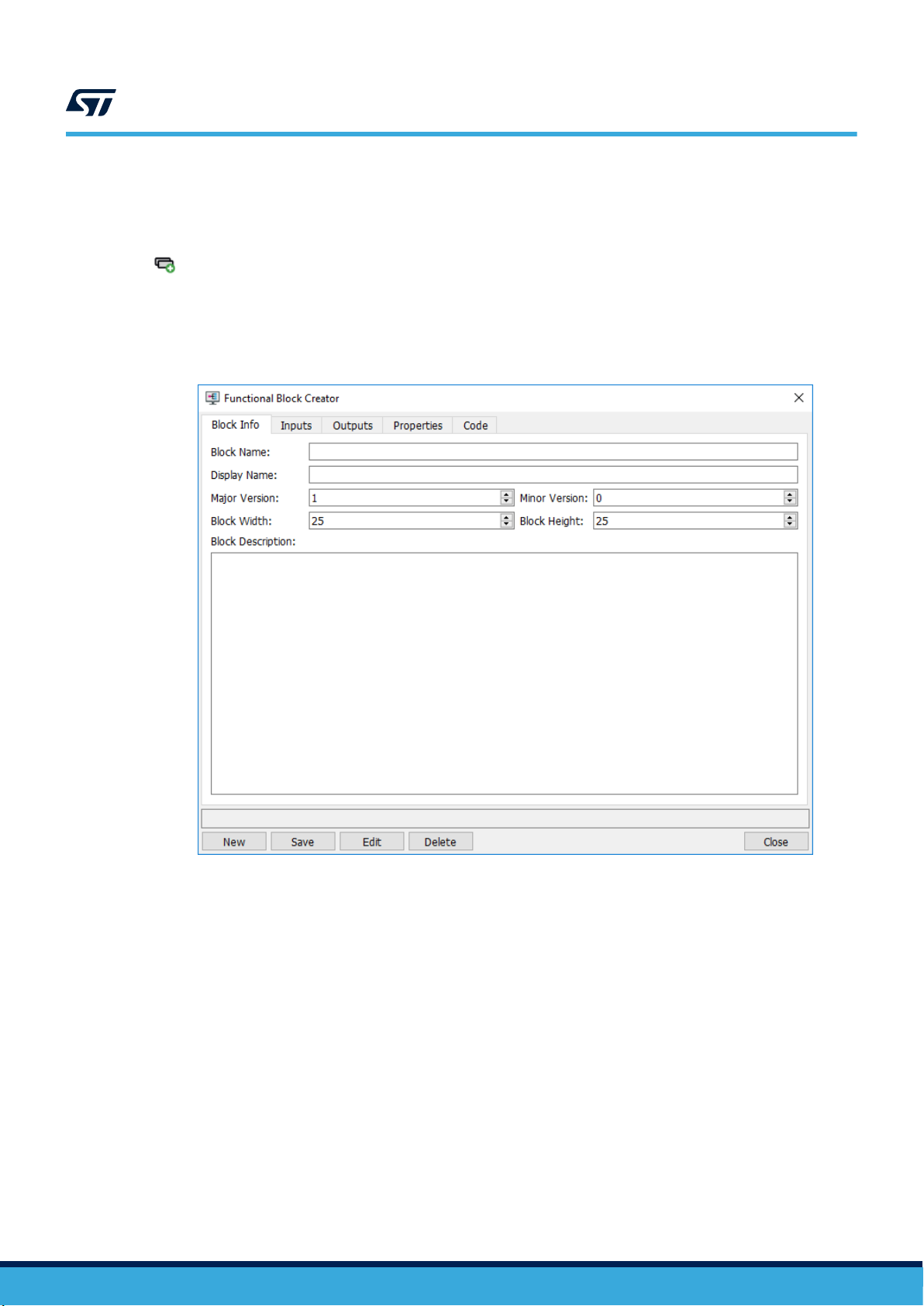
12.1 Function Block Creator
AlgoBuidler offers a Function Block Creator which allows defining a function block without knowledge of the XML
tags. The Function Block Creator can be executed from the Tools menu or from the Toolbar by pressing the button
(Function Block Creator).
User-defined function blocks are stored in the libraries which are stored in the user’s home directory
\STMicroelectronics\AlgoBuilder\Library.
The Function Block Creator also offers the possibility to edit or delete an already existing function block.
UM2373
Function Block Creator
Figure 44. Function Block Creator
UM2373 - Rev 9
In the Code section, a C code that represents the function block functionality can be entered. Input, Output and
Properties are referenced in C code using %NAME%[index] where NAME is the name of input, output or
property and index is number of the item in the array. All inputs and outputs are represented by array so the index
is mandatory even if only one item is in the array. Properties are scalar so the index is not used.
page 38/53
Page 39

13 Subdesign
AlgoBuilder offers the possibility to create a multi-level design. This feature allows encapsulating part of the
design into a standalone part called subdesign. This subdesign is represented by a single function block and can
be used multiple times in the main design and in all other designs. The subdesign can be shared between users.
The subdesigns significantly increase the clarity of a highly complex project.
UM2373
Subdesign
Figure 45. Principal of multi-level design
The subdesign allows implementing loops.
By default AlgoBuilder offers three templates for subdesign creation:
• !Subdesign Template is a generic empty subdesign
• !ForLoopTemplate is a subdesign intended for a loop, which is used if the number of iterations is known
before entering the loop
• !WhileLoopTemplate is a subdesign intended for a loop, which is executed until a defined condition is valid
Figure 46. Subdesign dock
Subdesigns can be created by double-clicking on the particular template. Existing subdesigns, listed in the
subdesigns dock or used in the design, can be opened in the same way. If a new or an existing subdesign is
open, AlgoBuilder creates a dedicated tab in the workspace.
UM2373 - Rev 9
page 39/53
Page 40

UM2373
Subdesign
Figure 47. Main design and subdesign tabs
The subdesign can be saved in the same way as the main design by clicking on the icon (Save Design) or
(Save Design As). The subdesign can then be used in the main design or other subdesign. To use the
subdesign, drag and drop the particular item from the Subdesigns dock to the workspace.
To be able to connect a subdesign with another function block, input and output terminals must be defined for
each subdesign. The terminals can be added from the Subdesign library, which is active only if a subdesign is
being modified.
Figure 48. Subdesign terminals
Each terminal has three properties: size, name, and description. The size and name must be defined, moreover
the name must be unique in the subdesign. The description is optional. In the graphical design, the subdesign is
represented by the same rectangle with inputs and outputs as function blocks. The vertical order of inputs and
outputs is given by the vertical coordinate of the terminals inside the subdesign
Figure 49. Example of a subdesign block and its content
If a user modifies a particular subdesign, AlgoBuilder is able to detect it and offer to update to the latest version
for each instance of the subdesign. This check is done during either subdesign validation or C code generation for
the main design.
UM2373 - Rev 9
page 40/53
Page 41

UM2373
Subdesign
Figure 50. Subdesign update
Note: The following two cases of a subdesign are not allowed:
1. A subdesign shall not be embedded within itself as this would create recursive calls and an infinite loop. This is
prevented by checking the subdesign name.
2. A subdesign 2 is permitted to be embedded within a subdesign 1 (refer to Figure 45), but subdesign 1 shall not
be further embedded in the subroutine. This is checked during design verification and the user is notified and
code generation is terminated.
Each subdesign is stored in a standalone XML file.
The templates for the for and while loop contain several function blocks which are mandatory. These blocks
cannot be deleted.
Mandatory function blocks are following:
For loop:
• Cycle Count (input) … defines the number of iterations which will be executed
• Cycle Index (output) … returns the number of current iterations
• Break Condition (input) … allows terminating the loop execution before reaching the cycle count
While loop:
• Cycle Index (output) … returns the number of current iterations
• Break Condition (input) … terminates the loop execution
Figure 51. Example of loop (calculates the sum of all items in the input buffer)
UM2373 - Rev 9
page 41/53
Page 42
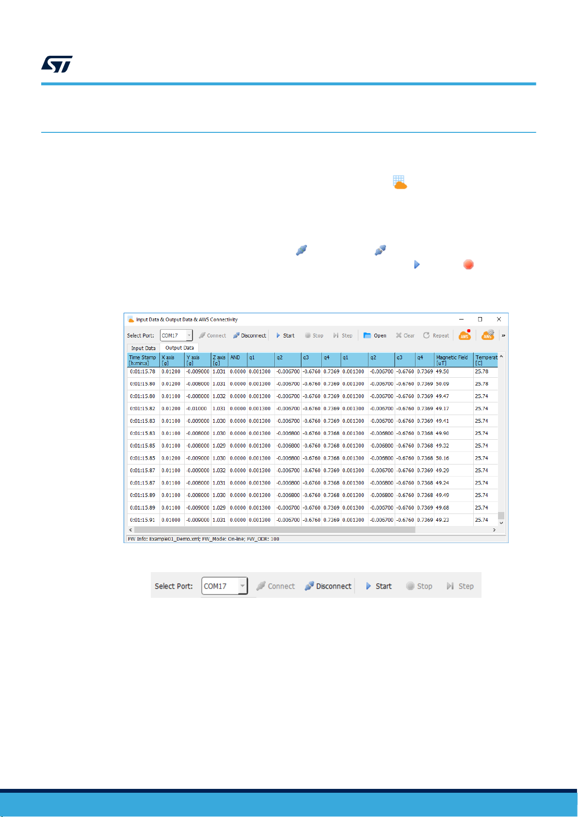
Input Data & Output Data Monitor & AWS Connectivity
14 Input Data & Output Data Monitor & AWS Connectivity
AlgoBuilder offers the possibility to quickly check outputs from running firmware without needing to execute
Unicleo-GUI. It also allows using offline data and publishing output data to the AWS cloud. All these features can
be used in a dedicated window, which can be opened by clinking on the icon (Input Data & Output Data &
AWS Connectivity) in the toolbar or the Tools menu.
UM2373
14.1
Output data monitor
The output data can be seen in textual form using the output data monitor. The output data monitor window has
its own toolbar to control the functionality. Connect and Disconnect buttons can be used to establish or
close the connection between AlgoBuilder and a connected STM32 device. Start and Stop buttons control
streaming data from a connected device to AlgoBuilder. The output data are visible in the Output data tab.
Figure 52. Input Data & Output Data Monitor and AWS connectivity
UM2373 - Rev 9
Figure 53. Output Data control section
page 42/53
Page 43

14.2 Offline data processing
AlgoBuilder allows sending previously recorded data to the connected STM32 device, which will process it instead
of actual data from sensors. This can be used to debug the algorithm using always the same input data as
algorithm stimulus. The data can be recorded and saved using the Datalog feature in Unicleo-GUI.
In order to use previously recorded data, the “Offline Data” option must be selected in the Data Rate Control
property in the Sensor Hub function block.
UM2373
Offline data processing
Figure 54. Offline Data settings in Sensor Hub
The input data can be loaded by clicking on the icon (Open). If the data in the file are stored at a higher rate
than the required data rate by the Sensor Hub, AlgoBuilder automatically resamples this data. The data can be
repeated in an infinite loop if the icon (Repeat) is pressed. All data can be processed automatically or one-by-
one by pressing the icon
Output Data tabs.
(Step). Input data and appropriate output data are visible in the Input Data and
Figure 55. Input Data control section
UM2373 - Rev 9
page 43/53
Page 44
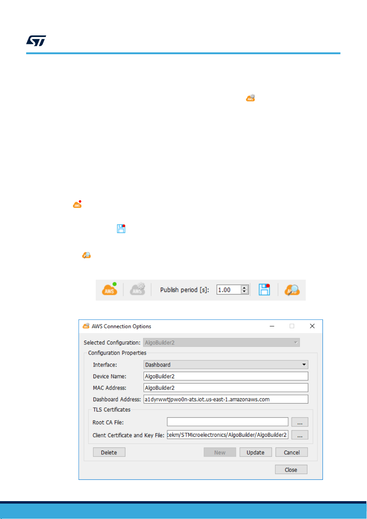
14.3 AWS (Amazon Web Services) connectivity
AlgoBuilder also allows sending data to the AWS cloud (Amazon Web Services), precisely to the IoT Core Service
UM2373
AWS (Amazon Web Services) connectivity
or to any MQTT broker. To set the connection parameters, click on the icon
enter all needed parameters.
AlgoBuilder supports three different interfaces (data structures):
• Generic MQTT: data are structured in generic JSON format that can be used by any other system
• Dashboard: data are structured to cooperate with ST Dashboard
• Symbios: data are structured to cooperate with ST internal tools
Based on the selected interface the connection parameters are adjusted. Mandatory parameters are as follows:
• Generic MQTT: Configuration Name, Topic, Broker Address and Certificates
• Dashboard: Device Name, MAC Address, Dashboard Address and Certificates
• Symbios: Thing, Name, Endpoint and Certificates
Other parameters are optional.
If the parameters are properly set, it is possible to establish a connection with the AWS Cloud by clinking on the
icon
By clicking on the same icon, the connection can be closed. The Publish period defines how often the data will be
sent to the cloud. The same data which are sent to the cloud can be saved to a file on the user's local hard drive
by clicking on the icon (Log messages published to AWS). These datalogs are located in the user’s directory
\STMicroelectronics\AlgoBuilder\DataLogs.
The data shown in the monitor can be filtered to the data sent to the cloud, this filter can be enabled by clicking on
the icon (Display only messages published to AWS).
(Start AWS Communication). If the connection is established, the red dot will change its color to green.
Figure 56. AWS control section
(AWS Connection options) and
Figure 57. AWS Connection Options (ST Dashboard interface)
UM2373 - Rev 9
page 44/53
Page 45
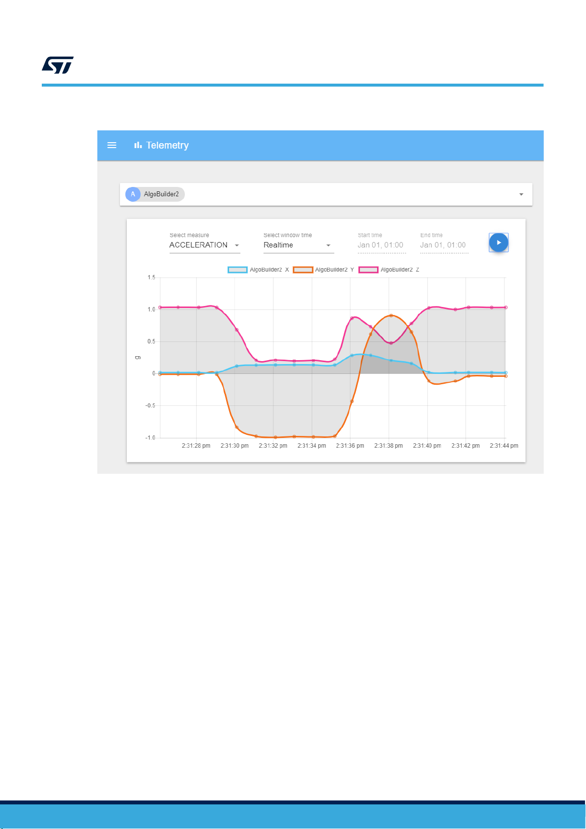
Figure 58. ST AWS Dashboard
UM2373
AWS (Amazon Web Services) connectivity
UM2373 - Rev 9
page 45/53
Page 46

Revision history
26-Mar-2018 1 Initial release
25-Jul-2018 2
27-Sep-2018 3
04-Dec-2018 4
05-Apr-2019 5
UM2373
Table 5. Document revision history
Date Version Changes
Updated Figure 1. AlgoBuilder application diagram, Figure 3. AlgoBuilder design, and
Figure 7. AlgoBuilder installer
Added SensorTile STEVAL-STLKT01V1 to Section 1.1 Overview and Section 1.2
Prerequisites
Updated Section 2.3 Application settings and Figure 10. Application Settings window
Updated Figure 13. AlgoBuilder main window
Updated Section 3.2 Library dock
Updated Table 1. AlgoBuilder toolbar default functions
Updated Table 2. AlgoBuilder installation libraries
Updated Section 6 Creating your first design
Updated Section 7 Programming the target
Added Section 7.2 SensorTile
Updated Section 8 Using Unicleo-GUI
Added Section 9.1 Function Block Creator
Updated Figure 7. AlgoBuilder installer
Updated Figure 13. AlgoBuilder main window
Added Figure 14. Using the Feedback function block
Added Section 5. Conditional Execution
Updated Table 2. AlgoBuilder installation libraries
Updated Figure 18. Sensor Hub properties and Figure 22. Generated code in
algo_builder.c file
Added Section 10. FFT (Fast Fourier Transform)
Minor textual updates
Addition of subdesign feature:
Updated Figure 7. AlgoBuilder installer
Updated Figure 13. AlgoBuilder main window
Added Secion 3.3 Subdesigns dock
Updated Table 1. AlgoBuilder toolbar default functions and Table 2. AlgoBuilder
installation libraries and
Added Secion 12 Subdesign
Added X-NUCLEO-IKS01A3 expansion board
Updated Section 1.1 Overview
Updated Figure 7 AlgoBuilder installer
Updated Section 2.3 Application settings
Updated Section 3 Using AlgoBuilder
Updated Table 1. AlgoBuilder toolbox default functions
Updated Section 8.2 SensorTile
Added Section 9.3 Set Toolbox buttons order
Updated Section 11.1 Function Block Creator
Added Section 13 Output Data Monitor & AWS Connectivity
UM2373 - Rev 9
page 46/53
Page 47

Date Version Changes
18-Jun-2019 6
19-Aug-2019 7
24-Oct-2019 8
20-Oct-2020 9
UM2373
Added SensorTile.box STEVAL-MKSBOX1V1
Updated Section 2.3 Application settings
Updated Table 3. AlgoBuilder suported libraries
Added Section 8.3 SensorTile.box
Added Section 13.1 Output data monitor
Added Section 13.2 Offline data processing
Added Section 13.3 AWS (Amazon Web Services) connectivity
Added STM32CubeIDE compiler (Section 1.1 Overview, Section 1.2 Prerequisites)
Updated Section 2.3 Application settings
Updated Table 1. AlgoBuilder toolbar default functions
Updated Section 7 Creating your first design
Updated Section 8.1 STM32 Nucleo board
Updated Section 8.3 SensorTile.box
Replaced STSW-LINK004 with STM32CubeProgrammer throughout user manual
Updated Section 1.2 Prerequisites
Updated Introduction
Updated Section 1.1 Overview and Section 1.2 Prerequisites
Updated Figure 5. AlgoBuilder principle of operation
Updated Section 2.1 Installing the software
Updated Figure 8. AlgoBuilder icon, Figure 9. Application Settings menu option,
Figure 12. Network Update Settings window, Figure 13. AlgoBuilder main window,
Table 1. AlgoBuilder toolbar default functions and Figure 16. AlgoBuilder Firmware
Settings window
Updated Section 8.3 SensorTile.box or STWIN
Added Section 11 Finite State Machine (FSM) and Machine Learning Core (MLC)
UM2373 - Rev 9
page 47/53
Page 48

UM2373
Contents
Contents
1 Description ........................................................................2
1.1 Overview .....................................................................2
1.2 Prerequisites ..................................................................2
1.3 Terms and references ...........................................................3
1.4 Principle of operation ...........................................................5
2 Getting started ....................................................................6
2.1 Installing the software ...........................................................6
2.2 Running the software for the first time .............................................7
2.3 Application settings .............................................................8
2.4 Network update settings.........................................................9
3 Using AlgoBuilder ................................................................10
3.1 Workspace ...................................................................11
3.2 Library dock ..................................................................11
3.3 Subdesigns dock..............................................................11
3.4 Description dock ..............................................................11
3.5 Properties dock ...............................................................12
3.6 Toolbar ......................................................................13
4 Data types ........................................................................15
5 Conditional Execution ............................................................16
6 Libraries..........................................................................17
7 Creating your first design.........................................................18
8 Programming the target...........................................................21
8.1 STM32 Nucleo board ..........................................................21
8.2 SensorTile ...................................................................21
8.3 SensorTile.box or STWIN.......................................................22
9 Using Unicleo-GUI ................................................................24
9.1 Data visualization .............................................................24
9.2 Data input....................................................................31
9.3 Set Toolbox Buttons order ......................................................32
UM2373 - Rev 9
page 48/53
Page 49

UM2373
Contents
10 FFT (Fast Fourier Transform) .....................................................33
11 Finite State Machine (FSM) and Machine Learning Core (MLC).....................35
12 Creating your own function block .................................................36
12.1 Function Block Creator .........................................................38
13 Subdesign........................................................................39
14 Input Data & Output Data Monitor & AWS Connectivity ............................42
14.1 Output data monitor ...........................................................42
14.2 Offline data processing.........................................................43
14.3 AWS (Amazon Web Services) connectivity ........................................44
Revision history .......................................................................46
UM2373 - Rev 9
page 49/53
Page 50

UM2373
List of tables
List of tables
Table 1. AlgoBuilder toolbar default functions...................................................... 13
Table 2. AlgoBuilder installation libraries ......................................................... 17
Table 3. AlgoBuilder supported libraries ......................................................... 17
Table 4. Function block XML tags.............................................................. 36
Table 5. Document revision history ............................................................. 46
UM2373 - Rev 9
page 50/53
Page 51

UM2373
List of figures
List of figures
Figure 1. AlgoBuilder function block ............................................................3
Figure 2. AlgoBuilder design .................................................................3
Figure 3. STM32 Nucleo (NUCLEO-F401RE) plus X-NUCLEO-IKS01A2 ...................................3
Figure 4. Unicleo-GUI .....................................................................4
Figure 5. AlgoBuilder principle of operation ....................................................... 5
Figure 6. AlgoBuilder installer ................................................................6
Figure 7. AlgoBuilderSuite installer .............................................................6
Figure 8. AlgoBuilder icon ...................................................................7
Figure 9. Application Settings menu option .......................................................8
Figure 10. Application Settings window ........................................................... 8
Figure 11. Network Update Settings menu option....................................................9
Figure 12. Network Update Settings window .......................................................9
Figure 13. AlgoBuilder main window............................................................ 10
Figure 14. Using the Feedback function block ..................................................... 15
Figure 15. Conditional Execution .............................................................. 16
Figure 16. AlgoBuilder Firmware Settings window ..................................................18
Figure 17. Sensor Hub function block ...........................................................18
Figure 18. Sensor Hub properties.............................................................. 18
Figure 19. Sensor Hub, Acceleration[g], Graph function blocks ......................................... 18
Figure 20. Graph properties.................................................................. 19
Figure 21. Sensor Hub, Acceleration[g], Graph function blocks ......................................... 19
Figure 22. Generated code in algo_builder.c file ....................................................20
Figure 23. System Workbench for STM32 output ................................................... 20
Figure 24. Program target icon and selection box................................................... 21
Figure 25. STM32 Nucleo board, SensorTile cradle SWD connectors ..................................... 21
Figure 26. STM32ST-Link programmer and SensorTile.box interconnection ................................. 22
Figure 27. Programming SensorTile.box or STWIN in DFU mode ........................................23
Figure 28. Bar function block and example of data visualization in Unicleo-GUI ..............................24
Figure 29. Fusion function block and example of data visualization in Unicleo-GUI ............................25
Figure 30. Graph function block and example of data visualization in Unicleo-GUI ............................ 26
Figure 31. Histogram function block and example of data visualization in Unicleo-GUI .........................26
Figure 32. Logic Analyzer function block and example of data visualization in Unicleo-GUI ...................... 27
Figure 33. 3D Plot function block and example of data visualization in Unicleo-GUI ........................... 28
Figure 34. Scatter Plot function block and example of data visualization in Unicleo-GUI ........................ 29
Figure 35. Value function block and example of data visualization in Unicleo-GUI .............................30
Figure 36. Input Value function blocks ........................................................... 31
Figure 37. Input Values in Unicleo-GUI ..........................................................31
Figure 38. Set Toolbox Buttons Order window ..................................................... 32
Figure 39. FFT function block ................................................................33
Figure 40. FFT and FFT Plot connections ........................................................ 33
Figure 41. Frequency spectrum in Unicleo-GUI .................................................... 34
Figure 42. Example of design with FSM / MLC..................................................... 35
Figure 43. FSM / MLC function block properties .................................................... 35
Figure 44. Function Block Creator ............................................................. 38
Figure 45. Principal of multi-level design .........................................................39
Figure 46. Subdesign dock ..................................................................39
Figure 47. Main design and subdesign tabs....................................................... 40
Figure 48. Subdesign terminals ............................................................... 40
Figure 49. Example of a subdesign block and its content.............................................. 40
Figure 50. Subdesign update................................................................. 41
Figure 51. Example of loop (calculates the sum of all items in the input buffer)............................... 41
Figure 52. Input Data & Output Data Monitor and AWS connectivity ...................................... 42
UM2373 - Rev 9
page 51/53
Page 52

UM2373
List of figures
Figure 53. Output Data control section .......................................................... 42
Figure 54. Offline Data settings in Sensor Hub..................................................... 43
Figure 55. Input Data control section ........................................................... 43
Figure 56. AWS control section ............................................................... 44
Figure 57. AWS Connection Options (ST Dashboard interface) .........................................44
Figure 58. ST AWS Dashboard ............................................................... 45
UM2373 - Rev 9
page 52/53
Page 53

UM2373
IMPORTANT NOTICE – PLEASE READ CAREFULLY
STMicroelectronics NV and its subsidiaries (“ST”) reserve the right to make changes, corrections, enhancements, modifications, and improvements to ST
products and/or to this document at any time without notice. Purchasers should obtain the latest relevant information on ST products before placing orders. ST
products are sold pursuant to ST’s terms and conditions of sale in place at the time of order acknowledgement.
Purchasers are solely responsible for the choice, selection, and use of ST products and ST assumes no liability for application assistance or the design of
Purchasers’ products.
No license, express or implied, to any intellectual property right is granted by ST herein.
Resale of ST products with provisions different from the information set forth herein shall void any warranty granted by ST for such product.
ST and the ST logo are trademarks of ST. For additional information about ST trademarks, please refer to www.st.com/trademarks. All other product or service
names are the property of their respective owners.
Information in this document supersedes and replaces information previously supplied in any prior versions of this document.
© 2020 STMicroelectronics – All rights reserved
UM2373 - Rev 9
page 53/53
 Loading...