

Page 1

AN5378
Application note
STM32WB Series microcontrollers bring-up procedure
Introduction
The STM32WB Series microcontrollers are ultra-low-power devices which embed wireless functions compliant with both the
Bluetooth® Low Energy SIG specification v5.0 and / or IEEE 802.15.4-201. These protocols work on radio frequency which
abbreviates to RF.
The objective of this document is to provide detailed guidelines to optimize the application implementation.
The application is optimized through the following steps:
• Board and environment setup
• Device configuration
• Power supply
• HSE trimming
• Output power test
• Sensitivity test
• Packet exchange test
• Power consumption in advertising mode
• RF tests for certification
• RF tests for production.
This application note uses the NUCLEO-WB55 board, MB1355C, as the reference hardware platform for the configuration. The
configuration settings can then be applied to a custom implementation.
Although this application addresses all the STM32WB Series microcontrollers' wireless functions, the Bluetooth® Low Energy
standard is used as the implementation example for the STM32WB Series microcontrollers' dedicated application. The same
process, however, is used for the IEEE 802.15.4-201 standard implementation.
AN5378 - Rev 2 - May 2020
For further information contact your local STMicroelectronics sales office.
www.st.com
Page 2
1 General information
This document applies to the STM32WB Series dual-core Arm®-based microcontroller.
Specific examples will be based on STM32WB55 devices but they apply to the whole Series.
Note: Arm is a registered trademark of Arm Limited (or its subsidiaries) in the US and/or elsewhere.
AN5378
General information
AN5378 - Rev 2
page 2/22
Page 3
2 Board setup
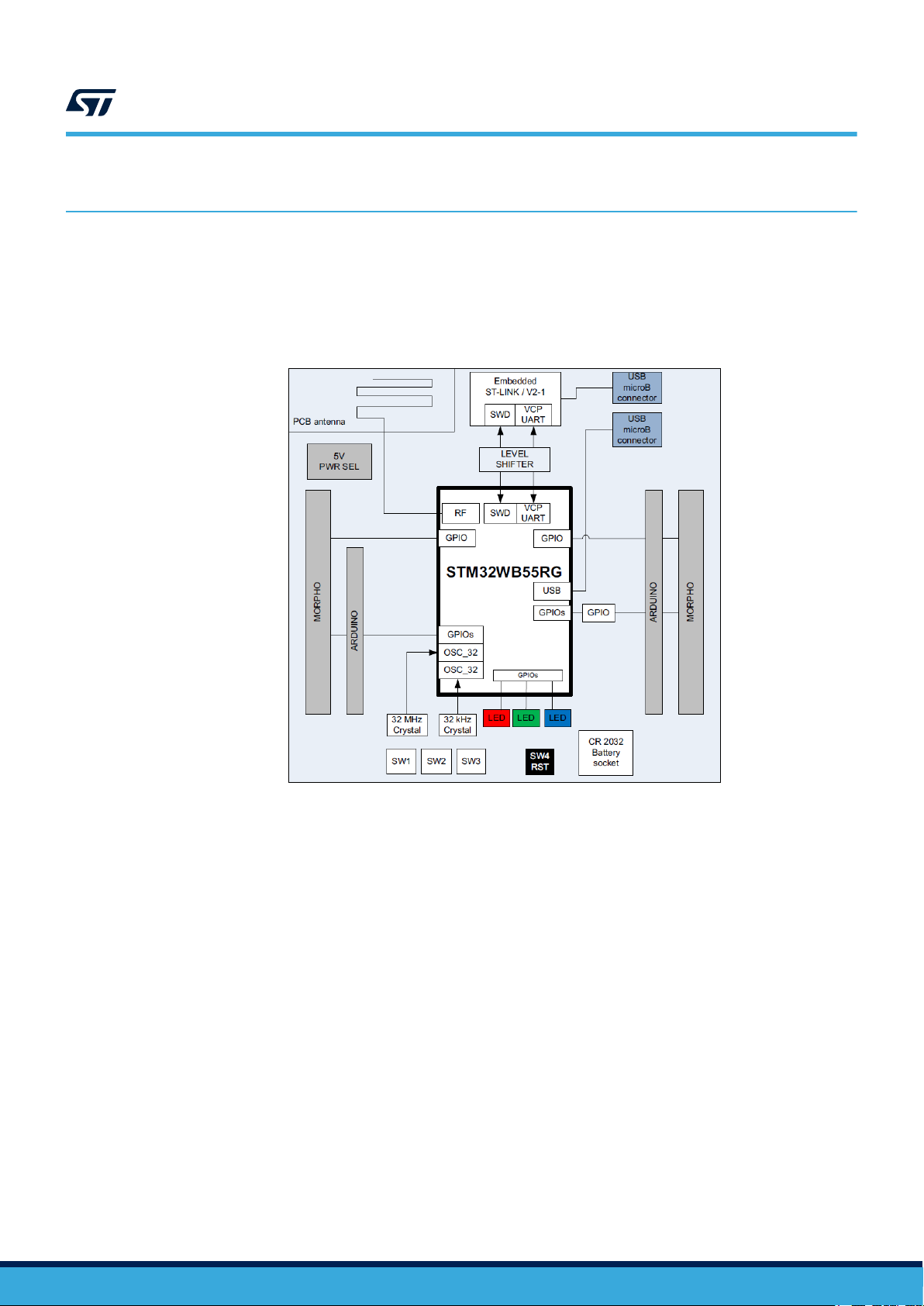
The MB1355C NUCLEO-WB55 board is designed around the STM32WB55RG microcontroller in a 68-pin
VFQFPN68 package. This board is included in the P-NUCLEO-WB55 pack with a USB dongle.
The hardware block diagram in Figure 1 illustrates the connection between the MCU and peripherals (ST-LINK/
V2-1, push buttons, LEDs, Arduino™ UNO V3 connector and ST-Morpho connectors).
AN5378
Board setup
Figure 1. STM35WB55RG interface block diagram
For the hardware layout and configuration details of the MB1355C board, refer to the Bluetooth® Low Energy and
802.15.4 Nucleo pack based on STM32WB Series microcontrollers user manual (UM2435).
By default, the MB1355C board is configured to output the RF signal through the PCB antenna path. So, C35 is
fitted and C38 not fitted as shown in Figure 2.
AN5378 - Rev 2
page 3/22
Page 4
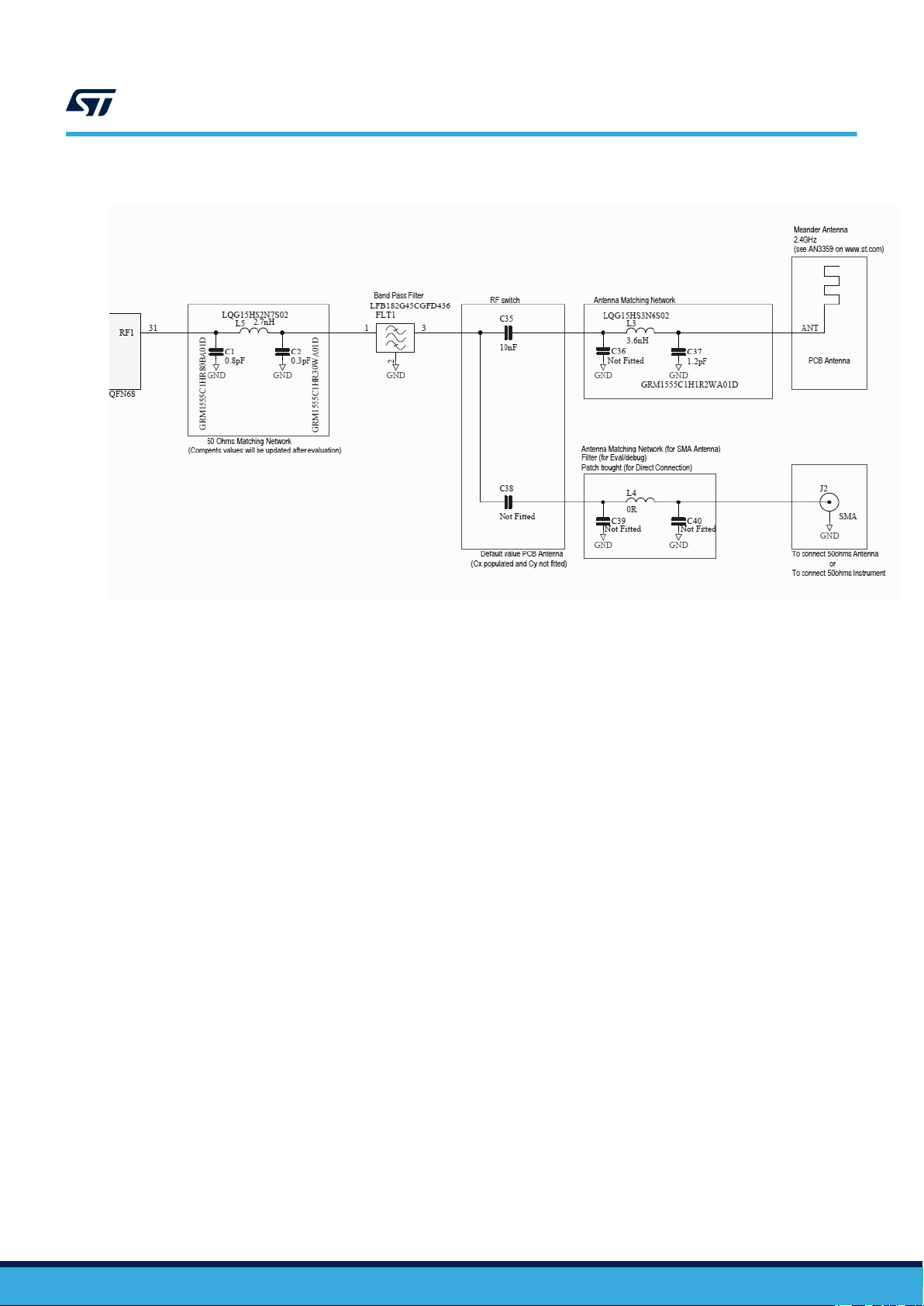
Figure 2. MB1355C antenna configuration
AN5378
Board setup
To perform certain tests, the RF signal has to be directed through the SMA path. In this case, C35 must be
removed and C38 fitted. An SMA board edge connector must also be soldered to J2.
AN5378 - Rev 2
page 4/22
Page 5
3 Environment setup
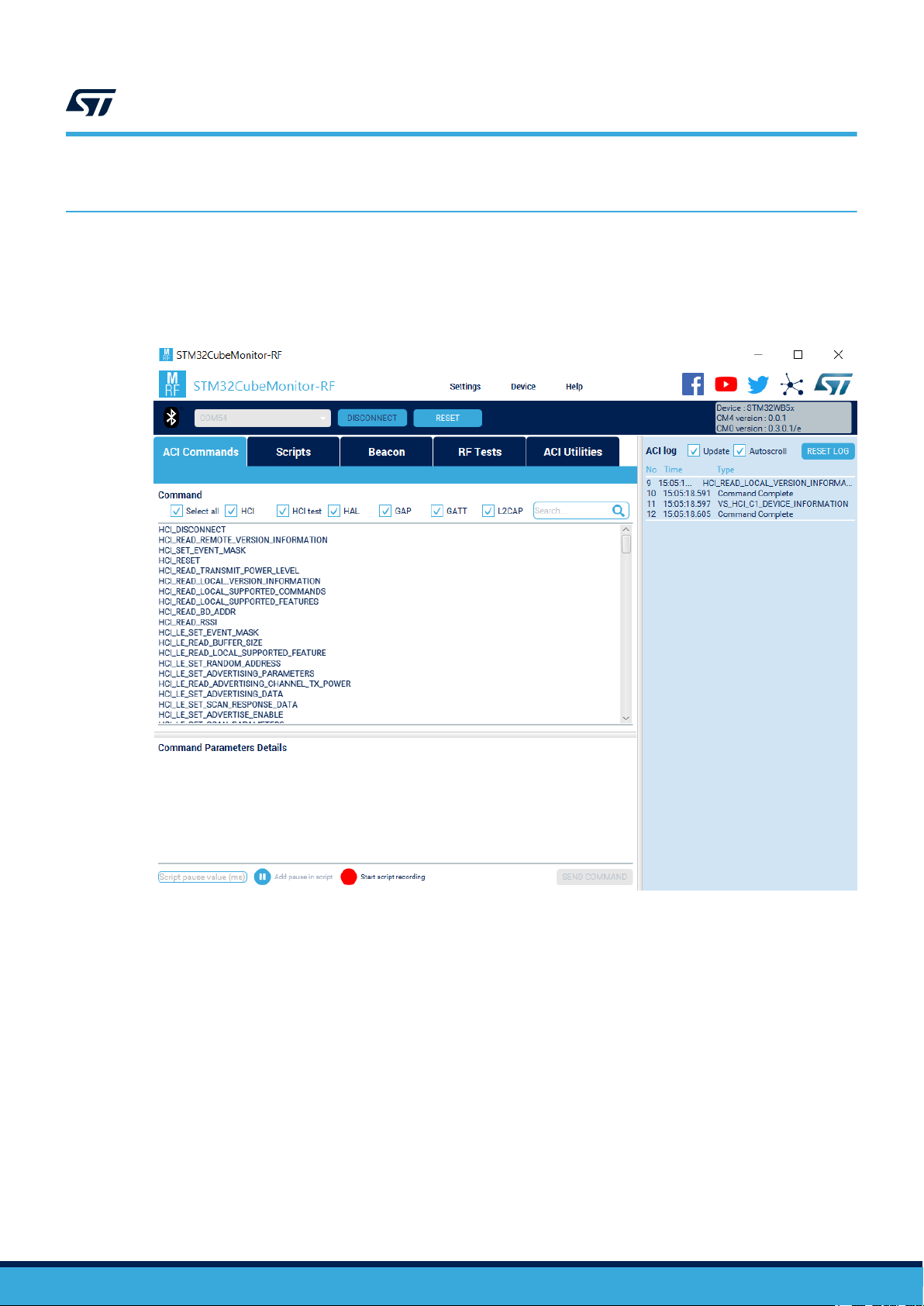
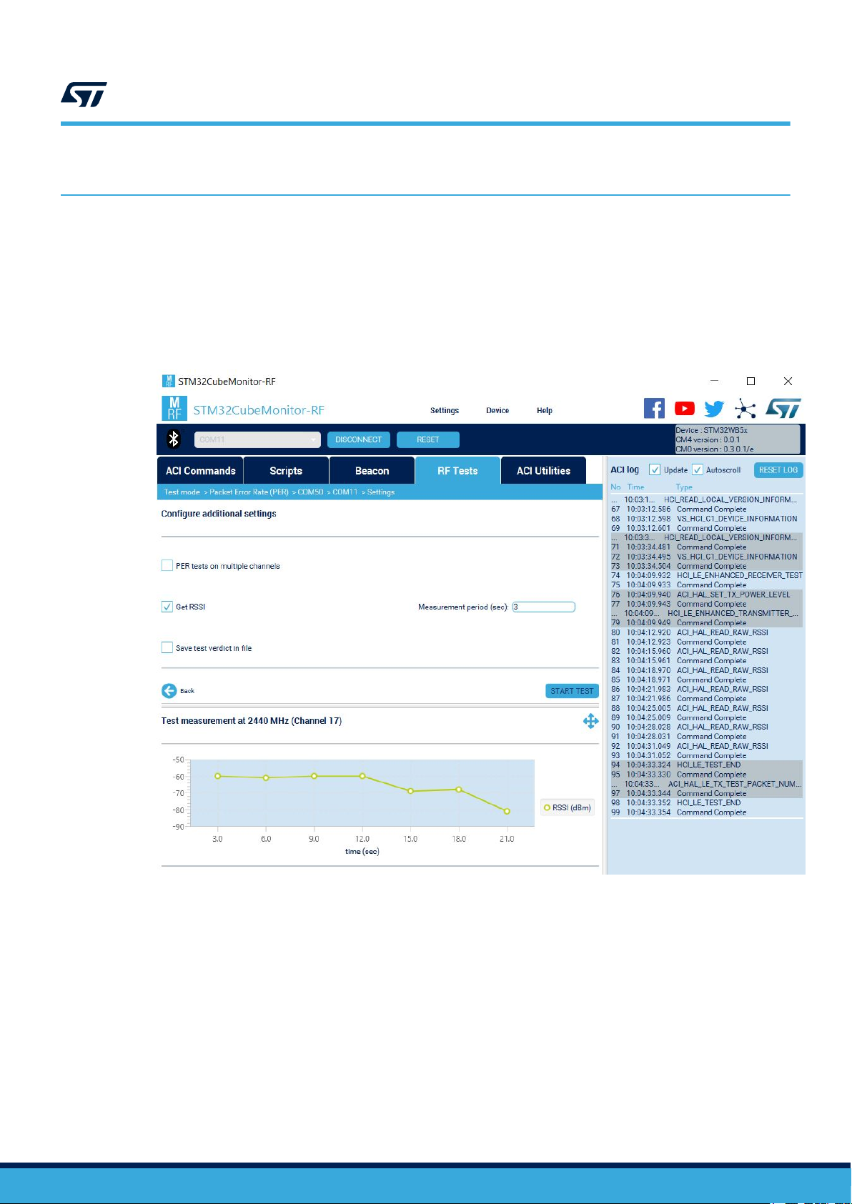
STM32CubeMonitor-RF is a tool to provide a radio performance test environment for the STM32WB Series
microcontrollers. It provides both transmission and reception tests, and PER measurement facilities. Figure 3
illustrates a typical screen representation. This software package is freely available on www.st.com.
Figure 3. STM32CubeMonitor-RF screen illustration
AN5378
Environment setup
AN5378 - Rev 2
For a complete description of this tool software, refer to STM32CubeMonitor-RF software tool for wireless
performance measurements (UM2288). The M4 transparent mode firmware must be programmed on the
STM32WB Series microcontroller to use STM32CubeMonitor-RF.
page 5/22
Page 6
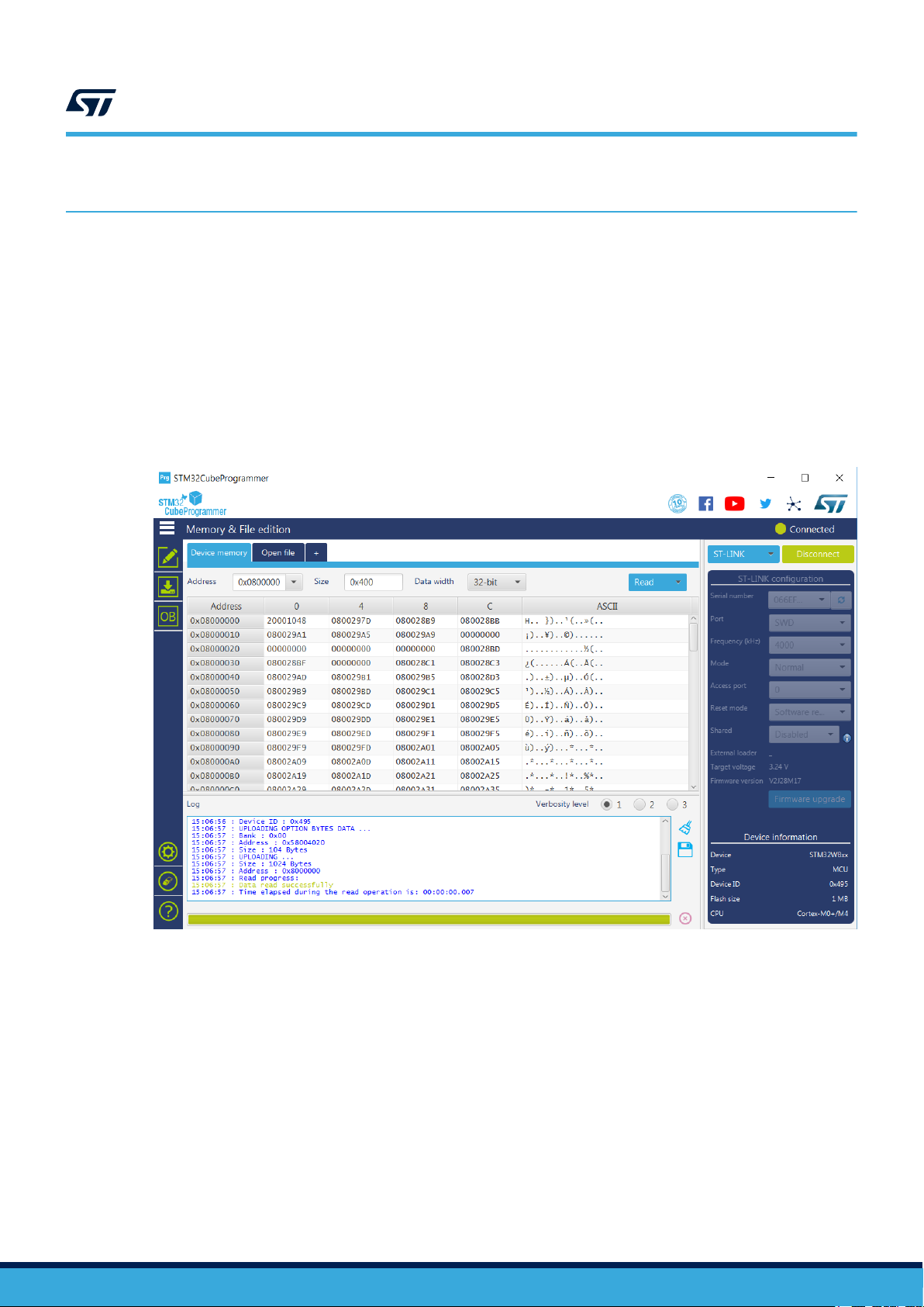
4 Device configuration
STM32CubeProg is the tool used to program STM32 products and provides a user friendly environment for
programming and validating the device memory through both:
• The debug interface (JTAG and SWD) – Refer to, for example, Multiprotocol wireless 32-bit MCU Arm®A-
based Cortex®-M4 with FPU, Bluetooth® Low-Energy and 802.15.4 radio solution reference manual
(RM0434) for the STM32WB55 devices.
• The bootloader interface (UART, USB DFU, I2C, SPI, and CAN) – Refer to, for example, Multiprotocol
wireless 32-bit MCU Arm®-based Cortex®-M4 with FPU, Bluetooth® Low-Energy and 802.15.4 radio solution
reference manual (RM0434) for the STM32WB55 devices.
The STM32CubeProg interface is illustrated in Figure 4. This software is freely available on www.st.com.
Figure 4. STM32CubeProg interface illustration
AN5378
Device configuration
AN5378 - Rev 2
For a complete description of this software tool, refer to STM32CubeProgrammer software description user
manual (UM2237).
For the Bluetooth® Low Energy, the direct test mode (DTM) is used to send instructions through the application
commands interface (ACI) and host commands interface (HCI) to the STM32WB Series microcontroller.
To program the STM32WB Series microcontroller on the MB1355C, follow the procedure ‘How to flash the
wireless coprocessor binary’ described in Getting started with STM32CubeWB for STM32WB Series user manual
(UM2550). The stm32wb5x_BLE_Stack_fw firmware must be flashed in the Arm® Cortex®-M0+ coprocessor
and the STM32WB Series microcontrollers example BLE_TransparentMode must be flashed in the Arm
Cortex®-M4 processor. Refer to Getting started with STM32CubeWB for STM32WB Series user manual
(UM2550) for firmware location.
®
page 6/22
Page 7
5 Power supply
Power up the board with the firmware loaded in both the Arm® Cortex®-M0+ (stm32wb5x_BLE_Stack_fw) and
Arm® Cortex®-M4 (BLE_TransparentMode) as described in Section 4 .
Using a multimeter, measure the voltage at the following points (refer to the board schematic for more
information):
• VDD
• VDDA
• VBAT
• VDDSMPS (does not apply to the STM32WBx0)
• VFBSMPS (does not apply to the STM32WBx0)
• VDDRF
• VDDUSB (does not apply to the STM32WBx0).
On the MB1355C, the maximum available voltage is 3.3V due to the embedded level shifters. The VDD, VBAT,
VDDUSB, VDDA and VDDSMPS power supplies by default are connected to a global power supply named
VDD_MCU and the voltage level can be checked at JP2.
More generally, the measured pin voltage must be aligned with the following values if the SMPS is enabled.
AN5378
Power supply
Symbol Parameter Conditions Min Max Unit
VDD Standard operating voltage -
ADC or COMP used
VDDA Analog supply voltage
VBAT Backup operating voltage - 1.55 3.6
VDDSMPS SMPS operating voltage - 1.71 3.6
VFBSMPS SMPS feedback voltage - 1.4 3.6
VDDRF Minimum RF voltage - 1.71 3.6
VDDUSB USB supply voltage
1. STM32WBx0 min = 2V
2. STM32WBx0 not concerned
VREFBUF used 2.4
ADC, COMP, VREFBUF
not used
USB used 3.0 3.6
USB not used 0 3.6
1.71
1.62
0
(1)
3.6
(2)
3.6
V
If the SMPS is disabled, VFBSMPS is connected to VDDSMPS.
For more information on how to use the SMPS on STM32WB Series microcontrollers, refer to Usage of SMPS on
STM32WB Series microcontrollers application note (AN5246).
Note: In the STM32WB Series microcontroller datasheet, the KPI BLE test cases power consumption refers to VDD
but RF static values refer to VDDRF + VDDSMPS.
AN5378 - Rev 2
page 7/22
Page 8

6 HSE trimming
The STM32WB microcontrollers use an external 32 MHz crystal oscillator with a frequency tolerance of less than
50 ppm for BLE, 40 ppm for 802.15.4 and when both BLE and 802.15.4 are used . The device includes internal
programmable capacitance that can be used to tune the crystal frequency in order to compensate for the PCB
parasitic capacitance.
This is a very important procedure because the RF depends on accurate clocks for its correct operation. A
deviation in clock frequency affects the radio frequency directly which results in a degraded RF performance,
violating legal requirements or in the worst case leading to a non-functional system.
Precise HSE frequency trimming using STM32 wireless MCUs application note (AN5042) describes three HSE
tuning methods for the STM32WB Series microcontrollers.
The X-CUBE-CLKTRIM expansion software illustrates the trimming of an HSE crystal oscillator in order to reach
the high-accuracy frequency required by RF applications.
An easy way to verify the correct centering of the HSE crystal oscillator is to program the device with a carrier
wave on CH17 (2440 MHz) and to measure the accuracy of the tone frequency with a spectrum analyzer. To do it,
follow this procedure:
1. Connect the MB1355C board to the spectrum analyzer through an RF cable if there is an SMA connector on
J2 (in that case, remove C35 and fit C38), otherwise plug a 2.4 GHz antenna into the input port of the
instrument.
2. Power up the MB1355C.
3. Set the spectrum analyzer to: SPAN = 500 kHz, RBW and VBW AUTO
AN5378
HSE trimming
AN5378 - Rev 2
page 8/22
Page 9

AN5378
HSE trimming
4. With STM32CubeMonitor-RF, connect to the STM32WB Series microcontroller and run a START TONE
(transmit test) with the parameters show in Figure 5 (in ToneONE mode, length of data and packet payload
are ignored):
Figure 5. STM32CubeMonitor-RF configuration example
AN5378 - Rev 2
5. The accuracy of the frequency is determined from the tone obtained on the spectrum analyzer.
page 9/22
Page 10

AN5378
HSE trimming
6. In Figure 6, the tone measured for the channel 17 is at 2.439997596 GHz which is within the limits defined
by the specification:
– 802.15.4: +/-96.2 kHz at 2405 MHz and +/-99.2 kHz at 2480 MHz
– BLE: +/-50 kHz for all channels
Figure 6. Resulting spectrum analyzer output
AN5378 - Rev 2
page 10/22
Page 11

7 Output power test
The power output test is the main test to validate the transmission chain is working properly. The test procedure is
given here:
1. Connect the MB1355C board to the spectrum analyzer through an RF cable using an SMA connector on J2
(in that case, C35 is not fitted and C38 is soldered), otherwise plug a 2.4 GHz antenna into the input port of
the instrument.
2. Power up the MB1355C.
3. Set the spectrum analyzer to: SPAN = 500 kHz, RBW and VBW AUTO
4. Once the STM32WB Series microcontroller is started, use the STM32CubeMonitor-RF and run a START
TONE (transmit test) with the parameters show in Figure 7 (in TONE mode, length of data and packet
payload are ignored):
Figure 7. STM32CubeMonitor-RF START TONE parameter configuration
AN5378
Output power test
AN5378 - Rev 2
5. With the peak search function of the marker menu, check the power of the tone obtained when 0 dBm is
programmed at the output of the chip.
page 11/22
Page 12

Figure 8. Measured output power at 0 dB output
AN5378
Output power test
In Figure 8, the power is measured by programming the STM32WB Series microcontroller to output 0dBm, less
the losses of the application board which includes: components, tracks and any measurement cable.
AN5378 - Rev 2
page 12/22
Page 13

8 Sensitivity test
The sensitivity test validates the quality of the receiving chain with the following procedure:
1. Connect the SMA connector J2 (C35 is not fitted and C38 is soldered) of the MB1355C board to a signal
generator through a RF cable (with no significant loss). Make sure the generator sends the packets as
defined in the specification.
2. Power up the MB1355C.
3. Once the STM32WB Series microcontroller is started, use the STM32CubeMonitor-RF to run a START RX
(receive test) with the parameters show in Figure 9:
AN5378
Sensitivity test
Figure 9. STM32CubeMonitor-RF receive test configuration
AN5378 - Rev 2
4. With the signal generator at the same frequency as the STM32WB Series microcontroller, decrease the
power until the PER reaches 30.8%.
The power obtained for PER = 30.8% corresponds to the sensitivity.
page 13/22
Page 14
9 Packet exchange test
Unlike previous tests performed in conducted mode (even if they are also possible in radiated mode), this test is
in over the air (OTA) mode. Two MB1355C are needed, one in TX and the other in RX mode. The RF signal is
exchanged between the two boards through the PCB antenna.
1. Power up the two MB1355C boards.
2. Once the STM32WB Series microcontroller is started, use the STM32CubeMonitor-RF to run the packet
error rate (PER) test with the parameters show in Figure 10:
Figure 10. STM32CubeMonitor-RF packet rate exchange configuration
AN5378
Packet exchange test
AN5378 - Rev 2
The received signal strength indication (RSSI) is displayed. This parameter provides an indication of the intensity
of the received signal.
page 14/22
Page 15

10 Power consumption in advertising mode
As with the previous test, the power consumption in advertising mode is in the OTA mode. This test uses one
MB1355C with an application which puts the device in advertising mode (examples are available in the firmware
package). The Transparent mode and the HCI commands start. The STM32CubeMonitor-RF advertising
sequence is also available for use. A power analyzer is connected in series to VDD (J2 on the MB1355C). Once
the board is powered up, the current has a shape similar to that shown below during advertising (see Figure 11) .
Figure 11. Advertising mode current output
AN5378
Power consumption in advertising mode
AN5378 - Rev 2
page 15/22
Page 16

AN5378
Power consumption in advertising mode
It is also possible to obtain this kind of measurement with STM32CubeMonPwr as illustrated in Figure 12. This
software is freely available on www.st.com.
Figure 12. STM32CubeMonPwr sample screen
AN5378 - Rev 2
page 16/22
Page 17

11 RF tests for certification
The STM32WB Series microcontrollers are compliant with the Bluetooth® Low Energy SIG specification v5.0 and
with IEEE 802.15.4-201. When the STM32WB Series microcontrollers support in a new RF design, the RF-PHY
layer must be tested.
For the Bluetooth® Low Energy SIG specification v5.0, the RF tests to be performed are (details in “RFPHY.TS.5.0.2” document):
• RF-PHY/TRM-LE/CA/BV-01-C [output power, no constant tone extension]
• RF-PHY/TRM-LE/CA/BV-03-C [in-band emissions, uncoded data at 1 Ms/s]
• RF-PHY/TRM-LE/CA/BV-05-C [modulation characteristics, uncoded data at 1 Ms/s]
• RF-PHY/TRM-LE/CA/BV-06-C [carrier frequency offset and drift, uncoded data at 1 Ms/s, preamble through
payload]
• RF-PHY/TRM-LE/CA/BV-08-C [in-band emissions at 2 Ms/s]
• RF-PHY/TRM-LE/CA/BV-10-C [modulation characteristics at 2 Ms/s]
• RF-PHY/TRM-LE/CA/BV-12-C [carrier frequency offset and drift at 2 Ms/s, preamble through payload]
• RF-PHY/RCV-LE/CA/BV-01-C [receiver sensitivity, uncoded data at 1 Ms/s]
• RF-PHY/RCV-LE/CA/BV-03-C [C/I and receiver selectivity performance, uncoded data at 1 Ms/s]
• RF-PHY/RCV-LE/CA/BV-04-C [blocking performance, uncoded data at 1 Ms/s]
• RF-PHY/RCV-LE/CA/BV-05-C [intermodulation performance, uncoded data at 1 Ms/s]
• RF-PHY/RCV-LE/CA/BV-06-C [maximum input signal level, uncoded data at 1 Ms/s]
• RF-PHY/RCV-LE/CA/BV-07-C [PER report integrity, uncoded data at 1 Ms/s]
• RF-PHY/RCV-LE/CA/BV-08-C [receiver sensitivity at 2 Ms/s]
• RF-PHY/RCV-LE/CA/BV-09-C [C/I and receiver selectivity performance at 2 Ms/s]
• RF-PHY/RCV-LE/CA/BV-10-C [blocking performance at 2 Ms/s]
• RF-PHY/RCV-LE/CA/BV-11-C [intermodulation performance at 2 Ms/s]
• RF-PHY/RCV-LE/CA/BV-12-C [maximum input signal level at 2 Ms/s]
• RF-PHY/RCV-LE/CA/BV-13-C [PER report integrity at 2 Ms/s]
For the IEEE 802.15.4-201, the RF tests to be performed are (details in “ZigBee 4 Document 095436r21
ZB_CSG-ZigBee-IP IEEE 802.15.4 Level Test Specification” document and ‘ZigBee Alliance IEEE 802.15.4 Test
spec–ZigBee Doc. 14-0332-01’ used for certification):
• TP/154/PHY24/TRANSMIT-01 (correct modulation)
• TP/154/PHY24/TRANSMIT-02 (error vector magnitude or EVM)
• TP/154/PHY24/TRANSMIT-03 (center frequency tolerance)
• TP/154/PHY24/TRANSMIT-04 (output power level)
• TP/154/PHY24/TRANSMIT-05 (power spectral density mask limits)
• TP/154/PHY24/RECEIVER-01 (sensivity PER)
• TP/154/PHY24/RECEIVER-02 (adjacent channel)
• TP/154/PHY24/RECEIVER-03 (alternate channel)
• TP/154/PHY24/RECEIVER-04 (maximum input power)
• TP/154/PHY24/RECEIVER-05 (energy detection ED)
• TP/154/PHY24/RECEIVER-06 (link quality indicator LQI)
• TP/154/PHY24/RECEIVER-07 (clear channel assessment CCA)
• TP/154/PHY24/TURNAROUND-TIME-01 (Rx to Tx turnaround time)
• TP/154/PHY24/TURNAROUND-TIME-02 (Tx to Rx turnaround time).
Moreover, depending on the country of use, the product must be compliant with one or more standards before it
can be sold. For example:
• FCC in North America
• RED in Europe
• JRL/MIC in Japan.
AN5378
RF tests for certification
AN5378 - Rev 2
page 17/22
Page 18

12 RF tests for production
Once the custom application board is designed and ready to be sent to production, the following tests must be run
to confirm that the application is correctly configured and the STM32WB Series microcontroller is working
correctly:
• Power supply
• Output power
• Receiver sensitivity
• Packet exchange test
• RF test certification.
The details of the tests are given in the previous sections.
AN5378
RF tests for production
AN5378 - Rev 2
page 18/22
Page 19

Revision history
08-Oct-2019 1 Initial release.
04-May-2020 2
AN5378
Table 1. Document revision history
Date Version Changes
Updated:
• Section 1 General information
• Section 4 Device configuration
• Section 6 HSE trimming
• Section 7 Output power test
• Section 9 Packet exchange test
• Section 11 RF tests for certification
AN5378 - Rev 2
page 19/22
Page 20

AN5378
Contents
Contents
1 General information ...............................................................2
2 Board setup .......................................................................3
3 Environment setup ................................................................5
4 Device configuration ..............................................................6
5 Power supply......................................................................7
6 HSE trimming......................................................................8
7 Output power test ................................................................11
8 Sensitivity test....................................................................13
9 Packet exchange test .............................................................14
10 Power consumption in advertising mode..........................................15
11 RF tests for certification ..........................................................17
12 RF tests for production ...........................................................18
Revision history .......................................................................19
AN5378 - Rev 2
page 20/22
Page 21

AN5378
List of figures
List of figures
Figure 1. STM35WB55RG interface block diagram ..................................................3
Figure 2. MB1355C antenna configuration .......................................................4
Figure 3. STM32CubeMonitor-RF screen illustration .................................................5
Figure 4. STM32CubeProg interface illustration ....................................................6
Figure 5. STM32CubeMonitor-RF configuration example ..............................................9
Figure 6. Resulting spectrum analyzer output .....................................................10
Figure 7. STM32CubeMonitor-RF START TONE parameter configuration ................................. 11
Figure 8. Measured output power at 0 dB output .................................................. 12
Figure 9. STM32CubeMonitor-RF receive test configuration...........................................13
Figure 10. STM32CubeMonitor-RF packet rate exchange configuration ...................................14
Figure 11. Advertising mode current output ....................................................... 15
Figure 12. STM32CubeMonPwr sample screen .................................................... 16
AN5378 - Rev 2
page 21/22
Page 22

AN5378
IMPORTANT NOTICE – PLEASE READ CAREFULLY
STMicroelectronics NV and its subsidiaries (“ST”) reserve the right to make changes, corrections, enhancements, modifications, and improvements to ST
products and/or to this document at any time without notice. Purchasers should obtain the latest relevant information on ST products before placing orders. ST
products are sold pursuant to ST’s terms and conditions of sale in place at the time of order acknowledgement.
Purchasers are solely responsible for the choice, selection, and use of ST products and ST assumes no liability for application assistance or the design of
Purchasers’ products.
No license, express or implied, to any intellectual property right is granted by ST herein.
Resale of ST products with provisions different from the information set forth herein shall void any warranty granted by ST for such product.
ST and the ST logo are trademarks of ST. For additional information about ST trademarks, please refer to www.st.com/trademarks. All other product or service
names are the property of their respective owners.
Information in this document supersedes and replaces information previously supplied in any prior versions of this document.
© 2020 STMicroelectronics – All rights reserved
AN5378 - Rev 2
page 22/22
 Loading...