

Page 1

SatLink VSAT User Guide
User Guide
Revision 14.1.1-2 – January 12th 2012
Networks without Barriers
Page 2

SatLink VSAT User Guide
Publication no. 101557
Rev 14.1.1-2
Copyright © 2006-2012 – STM Group, Inc.
Page 1 (182)
©
Copyright 2006-2012, STM Group, Inc.
All rights reserved. Reproduction, adaptation or translation without prior written
permission is prohibited, except as allowed under the copyright laws.
®
™
The names of products (hardware and/or software) mentioned herein are regarded to be
the property of their respective companies, regardless of whether or not registration is
indicated.
Notice
The information in this publication is subject to change without notice. STM Group, Inc.
makes no warranty of any kind with regard to this material, including, but not limited to,
the implied warranties or merchantability and fitness for particular purposes. Moreover,
STM shall not be held liable for errors that may occur herein or for incidental or
consequential damage in connection with the furnishing, performance, or use of this
material.
Page 3

SatLink VSAT User Guide
Publication no. 101557
Rev 14.1.1-2
Copyright 2006-2012 – STM Group, Inc.
Page 2 (182)
Table of Contents
1. INTRODUCTION .............................................................................................................................................. 5
1.1 ABOUT THIS USER GUIDE ............................................................................................................................. 6
1.2 INITIAL CONFIGURATION .............................................................................................................................. 6
1.3 SYMBOLS ...................................................................................................................................................... 7
2. UNPACKING ..................................................................................................................................................... 8
3. INSTALLATION ............................................................................................................................................... 9
3.1 BEFORE INSTALLATION ................................................................................................................................ 9
3.2 SATLINK VSAT IDU FRONT AND REAR PANELS ......................................................................................... 9
3.3 IDU INSTALLATION .................................................................................................................................... 13
3.4 ODU INSTALLATION .................................................................................................................................. 14
3.5 INTERFACE CONNECTIONS .......................................................................................................................... 15
4. CONNECTING A PC TO THE SATLINK VSAT ........................................................................................ 17
4.1 WINDOWS 7 TCP/IP CONFIGURATION ........................................................................................................ 17
4.2 WINDOWS XP TCP/IP CONFIGURATION ..................................................................................................... 19
5. USING THE SATLINK VSAT WEB INTERFACE ..................................................................................... 21
6. SATLINK VSAT CONFIGURATION AND LINE-UP USING THE WEB INTERFACE ...................... 22
6.1 LOG ON TO THE VSAT WEB INTERFACE .................................................................................................... 22
6.2 CONFIGURING VSAT PARAMETERS REQUIRED TO LOG ON TO THE HUB .................................................... 22
6.3 NAT CONFIGURATION USING THE WEB INTERFACE ................................................................................... 29
6.4 LINE-UP USING THE WEB INTERFACE ......................................................................................................... 29
6.5 TEST OF CONNECTION TO HUB ................................................................................................................... 33
6.6 PREPARE THE VSAT FOR NORMAL OPERATION ......................................................................................... 36
7. STATUS MONITORING USING THE SATLINK WEB INTERFACE ................................ .................... 39
7.1 SATELLITE INTERFACE STATUS .................................................................................................................. 39
7.2 STATISTICS ................................................................................................................................................. 41
7.3 DEVICE STATUS .......................................................................................................................................... 43
7.4 DHCP SERVER STATUS .............................................................................................................................. 44
8. USING THE COMMAND LINE INTERFACE OF THE SATLINK VSAT ............................................. 45
8.1 CLI USER ACCESS RIGHTS ......................................................................................................................... 45
8.2 ONLINE HELP ............................................................................................................................................. 45
8.3 LOGGING OF EVENTS .................................................................................................................................. 46
8.4 CLI COMMAND SUMMARY ......................................................................................................................... 47
9. SATLINK VSAT CONFIGURATION AND LINE-UP USING THE COMMAND LINE INTERFACE51
9.1 POWER ON AND LOG ON ............................................................................................................................ 51
9.2 INITIAL CONFIGURATION OF PARAMETERS ................................................................................................. 53
9.3 LINE-UP ...................................................................................................................................................... 62
9.4 TEST OF CONNECTION TO THE HUB ............................................................................................................ 67
9.5 PREPARE THE VSAT FOR NORMAL OPERATION ......................................................................................... 69
10. NETWORK ADDRESS TRANSLATION (NAT) ..................................................................................... 70
11. QUALITY OF SERVICE ............................................................................................................................ 74
11.1 CONFIGURING QOS FOR THE RETURN LINK ................................................................................................ 75
11.2 CONFIGURING THE VSAT FOR VOIP .......................................................................................................... 77
11.3 CONFIGURING THE VSAT FOR VIDEO (VIC) .............................................................................................. 77
11.4 DSCP AND DIFFSERV ................................................................................................................................. 78
Page 4

SatLink VSAT User Guide
Publication no. 101557
Rev 14.1.1-2
Copyright 2006-2012 – STM Group, Inc.
Page 3 (182)
12. BANDWIDTH ON DEMAND .................................................................................................................... 80
13. TRAFFIC INITIATED LOGON ................................................................................................................ 82
14. HEADER COMPRESSION ........................................................................................................................ 83
14.1 ENABLING HEADER COMPRESSION............................................................................................................. 83
14.2 DISABLE HEADER COMPRESSION ............................................................................................................... 84
15. ROUTING OF MULTICAST TRAFFIC .................................................................................................. 85
16. UPDATING THE VSAT SW ...................................................................................................................... 86
16.1 AUTOMATIC SOFTWARE UPDATE ............................................................................................................... 87
16.2 MANUAL SOFTWARE UPDATE .................................................................................................................... 88
16.3 RESTORING THE BACKUP SOFTWARE ......................................................................................................... 89
17. SATLINK AND DVB-S2 ............................................................................................................................. 90
17.1 DVB-S2 MODULATION ................................................................ .............................................................. 90
17.2 DVB-S2 CODING ....................................................................................................................................... 90
17.3 DVB-S2 CODING AND MODULATION CONTROL MODES ............................................................................ 92
17.4 DVB-S2 CONFIGURATION FOR 1910 IDUS WITH THE SATLINK 100 PLUG-IN CARD .................................. 93
18. SOFTWARE OPTIONS .............................................................................................................................. 95
18.1 GENERIC ROUTING ENCAPSULATION (GRE) AND IP TUNNELING ............................................................... 96
18.2 TCP PERFORMANCE ENHANCING PROXY (PEP) ......................................................................................... 97
18.3 HTTP ACCELERATION (HTTPA) ............................................................................................................... 99
18.4 RETURN LINK ACCESS CONTROL (RAC) .................................................................................................. 102
18.5 VLAN EXTENSION (802.1Q) .................................................................................................................... 104
18.6 ETHERNET USER PRIORITY (802.1P/D) ..................................................................................................... 105
18.7 DVB-S2 16-APSK ................................................................................................................................... 106
19. EXTENSIONS FOR MOBILE VSATS ................................................................................................... 108
19.1 TRANSMIT INHIBIT FUNCTION .................................................................................................................. 108
19.2 GPS INTERFACE ....................................................................................................................................... 110
19.3 RX LOCK SIGNAL ..................................................................................................................................... 111
19.4 OPTIMIZING THE MOBILE VSAT FOR RECOVERING CONTACT WITH THE NETWORK AFTER BLOCKINGS . 111
19.5 MOBILE VSAT LAN INTERFACE TO MOBILE ANTENNA CONTROLLER .................................................... 112
20. MESH VSATS ............................................................................................................................................ 118
21. DEFINITIONS, ACRONYMS AND ABBREVIATIONS ...................................................................... 123
22. REFERENCES ........................................................................................................................................... 125
APPENDIX A. ACCESSING THE COMMAND LINE INTERFACE VIA SERIAL CONSOLE PORT 126
APPENDIX B. TFTP SERVER ......................................................................................................................... 129
APPENDIX C. TELNET CLIENT .................................................................................................................... 130
APPENDIX D. TESTING THE CONNECTION TO THE VSAT ................................................................. 131
APPENDIX E. MANAGEMENT VIA SNMP ................................................................................................. 140
APPENDIX F. ODU INSTALLATION ............................................................................................................ 148
APPENDIX G. SATLINK 403X: INTERFACING VSAT RX/TX ANTENNAS .......................................... 154
Page 5

SatLink VSAT User Guide
Publication no. 101557
Rev 14.1.1-2
Copyright 2006-2012 – STM Group, Inc.
Page 4 (182)
APPENDIX H. MANUAL CONFIGURATION OF PARAMETERS NORMALLY CONFIGURED
AUTOMATICALLY FROM THE HUB .............................................................................................................. 157
APPENDIX I. IDU POWER CALIBRATION AND P1DB CONFIGURATION WITH BUCS OTHER
THAN THE SATLINK 403X ................................................................................................................................. 161
APPENDIX J. THE BOOT SW ........................................................................................................................ 164
APPENDIX K. TROUBLESHOOTING ........................................................................................................... 165
APPENDIX L. COMPLIANCE ........................................................................................................................ 177
APPENDIX M. STANDARDIZATION OF TIMING COMPENSATION ................................................ 179
APPENDIX N. RECEIVER AND TRANSMITTER AUTOSTART ............................................................. 180
APPENDIX O. ACCESSING THE FORWARD LINK SIGNALING ........................................................... 181
Page 6

SatLink VSAT User Guide
Publication no. 101557
Rev 14.1.1-2
Copyright 2006-2012 – STM Group, Inc.
Page 5 (182)
1. Introduction
The SatLink 1000, 1910, 2000, and 2900 are the indoor units (IDUs) of the SatLink family of DVB-RCS
VSATs. They perform several functions: they are satellite modems (at Layer 1); they handle data link
layer processing (at Layer 2) for both satellite and LAN communications; and they act as IP routers and
DHCP servers (at Layer 3). All SatLink IDUs provide an Ethernet 10/100 LAN interface for one or more
PCs to engage in two-way communication via a SatLink (or any DVB-RCS compliant) satellite network.
Figure 1: SatLink 1000, 1910, 2000, and 2900 Indoor Units (IDUs)
Figure 2: SatLink Outdoor Unit (ODU)
Page 7

SatLink VSAT User Guide
Publication no. 101557
Rev 14.1.1-2
Copyright 2006-2012 – STM Group, Inc.
Page 6 (182)
1.1 About this User Guide
This User Guide covers the installation and operation of the SatLink 1000/1910/2000/2900, commonly
also referred to as the indoor unit (IDU) of the DVB-RCS VSAT, together with the accompanying
outdoor unit (ODU) equipment. It is intended for DVB professionals, such as service providers and
installers. Therefore, it does not contain information for non-professional users, such as given in the user
manuals of consumer electronic products. The information given pertains to the following STM software
(SW) and hardware (HW) versions and releases:
SatLink IDU Software
STM SatLink Boot loader, P/N 101225, SW build 1.8.0.2 and later
STM SatLink Boot loader, P/N 106267, version 9.0.0 and later
STM SatLink Boot loader, P/N 120044 , Revision 14.0.0 and later
STM SatLink Boot loader, P/N 120511, Revision 14.1.0 and later
STM SatLink DVB-RCS VSAT Software, P/N 120208, version 14.1.0 and later
SatLink VSAT IDU Hardware models
STM SatLink 100 DVB-S2 Plug-in card for SatLink 1910, P/N 107261
STM SatLink 1000, P/N 103346
STM SatLink 1910, P/N 103798
STM SatLink 2000, P/N 120033
STM SatLink 2900, P/N 120510
Ku-band Equipment
Transceivers
STM SatLink 4033, P/N 104804
STM SatLink 4035, P/N 106546
1.2 Initial Configuration
The VSAT IDU must be configured before it can communicate via the satellite to and from the network
Hub. The parameters to be configured are explained in section 6.2.
The configuration of the VSAT IDU can be carried out using the following configuration tools:
Web-interface (basic configuration only)
Command Line Interface (CLI)
- Via RS232/Terminal emulator (e.g. HyperTerminal)
- Telnet
SNMP
The SatLink VSAT web interface is used as the main interface for initial configuration of the VSAT
parameters and is presented in section 6. The status monitoring of the VSAT using a web interface is
presented in section 7. Configuration via CLI is presented in section 9 and management via SNMP is
presented in Appendix E. The Web interface can be used for most common configuration tasks, while
advanced configuration is only available via SNMP and CLI.
Page 8

SatLink VSAT User Guide
Publication no. 101557
Rev 14.1.1-2
Copyright 2006-2012 – STM Group, Inc.
Page 7 (182)
1.3 Symbols
NOTE
Additional information that the reader should pay special attention to.
WARNING
System malfunction may occur if the warning information is violated.
Page 9

SatLink VSAT User Guide
Publication no. 101557
Rev 14.1.1-2
Copyright 2006-2012 – STM Group, Inc.
Page 8 (182)
2. Unpacking
Check that the following items are in the box received and then unpack.
SatLink 1000, 1910, 2000, or 2900
Stand for vertical placement (SatLink 1000 only)
AC adapter (SatLink 1000/2000 only )
Power cord
Brackets for 19‖ rack mounting (SatLink 1910 and SatLink 2900 only)
Page 10

SatLink VSAT User Guide
Publication no. 101557
Rev 14.1.1-2
Copyright 2006-2012 – STM Group, Inc.
Page 9 (182)
3. Installation
3.1 Before Installation
3.1.1 Safety
Follow these guidelines to ensure general safety:
Always comply with national and local electrical codes.
Keep the installation area clear and dust free during and after installation.
Keep tools and all components away from walking areas.
Do not wear loose clothing, jewelry (including rings and chains), or other items that might get caught
on the IDU, the ODU, or the interconnecting cables.
Do not work on the system or connect or disconnect cables during lightning storms.
Follow these guidelines when working with electrical equipment:
Disconnect all power and external cables before installing or removing a SatLink VSAT IDU.
Do not work alone when potentially hazardous conditions exist.
Never assume that power has been disconnected from a circuit; always check.
Do not act in any way that creates a potential hazard to people or makes the equipment unsafe.
Never install equipment that appears damaged.
Carefully examine your work area for possible hazards such as moist floors, unearthed power
extension cables and missing protective earths.
Should an electrical accident occur:
Be cautious – do not become a victim yourself
Turn off electrical power to the system.
If possible, send another person to get medical aid. Otherwise, assess the condition of the victim and
then call for help.
Determine if the victim needs artificial respiration or external cardiac compressions; then take
appropriate action.
3.1.2 Site Requirements
The VSAT IDU should be connected to 110/240 VAC, 50-60Hz power.
3.2 SatLink VSAT IDU Front and Rear Panels
3.2.1 SatLink 2000 Front and Rear Panel
Figure 3 : SatLink 2000 Front Panel
Page 11

SatLink VSAT User Guide
Publication no. 101557
Rev 14.1.1-2
Copyright 2006-2012 – STM Group, Inc.
Page 10 (182)
LED
Color: indicates
Power
Yellow: lights steadily when connected to the power supply and unit is powered. Flashes
when loading software.
Error
Red: lights steadily when an error event occurs and during reboot.
Satellite
Receive
White: flashes when the receiver is searching for the carrier.
Lights steadily when receiver is on and functioning properly.
Flashes when IP packets are received from the Satellite Interface (the Hub).
Transmit
White: flashes rapidly when a continuous wave (CW) is transmitted.
Lights steadily when the VSAT is logged on to the DVB-RCS Hub.
Flashes when IP packets are transmitted to the Satellite Interface (the Hub).
Ethernet
Link/Act
White: lights steadily when Ethernet connectivity is OK.
Flashes slowly when Ethernet packets are transferred via the Ethernet interface.
Status
For future use
Table 1: SatLink 2000 Front Panel LEDs
Figure 4 : SatLink 2000 Rear Panel
Item
Description
Power Connector
Connector for cable to the 24 V DC power transformer (external power supply provided
with STM SatLink 2000 VSAT)
Ethernet
Connector
RJ45 connector for IP traffic to connect to a PC, Ethernet switch, IP router etc. 10BASE-T
or 100BASE-T modes is detected automatically.
COM1 Connector
Nine pin connector for connecting CLI interface to a computer‘s DB-9 serial interface.
RX coaxial jack
Coaxial 75 F-type jack for the cable to the LNB.
TX coaxial jack
Coaxial 75 F-type jack for the cable to the BUC.
Table 2: SatLink 2000 Rear Panel Description
3.2.2 SatLink 1000 Front and Rear Panel
Figure 5: SatLink 1000 Front Panel
Page 12

SatLink VSAT User Guide
Publication no. 101557
Rev 14.1.1-2
Copyright 2006-2012 – STM Group, Inc.
Page 11 (182)
LED
Color: indicates
Power
White: lights steadily when power switch is on and unit has power. Flashes when loading
software.
Error
Red: lights steadily when an error event occurs and during reboot.
Satellite
Receive
White: flashes when the receiver is searching for the carrier.
Lights steadily when receiver is on and functioning properly.
Flashes when IP packets are received from the Satellite Interface (the Hub).
Transmit
White: flashes rapidly when a continuous wave (CW) is transmitted.
Lights steadily when the VSAT is logged on to the DVB-RCS Hub.
Flashes when IP packets are transmitted to the Satellite Interface (the Hub).
Ethernet
Link/Act
White: lights steadily when Ethernet connectivity is OK.
Flashes slowly when Ethernet packets are transferred via the Ethernet interface.
Table 3: SatLink 1000 Front Panel LEDs
Figure 6: SatLink 1000 Rear Panel
Item
Description
On/off switch
Power on (1) or off (0).
Power Connector
Connector for cable to the 24 V DC power transformer (external power supply provided
with SatLink 1000 VSAT)
Ethernet
Connector
RJ45 connector for IP traffic to connect to a PC, Ethernet switch, IP router, etc. 10BASET or 100BASE-T modes are detected automatically.
COM1 Connector
Nine pin connector for connecting CLI interface to a computer‘s DB-9 serial interface.
RX coaxial jack
Coaxial 75 F-type jack for the cable to the LNB.
TX coaxial jack
Coaxial 75 F-type jack for the cable to the BUC.
Table 4: SatLink 1000 Rear Panel Description
3.2.3 SatLink 1910 Front and Rear Panel
Figure 7: SatLink 1910 Front Panel
Page 13

SatLink VSAT User Guide
Publication no. 101557
Rev 14.1.1-2
Copyright 2006-2012 – STM Group, Inc.
Page 12 (182)
LED
Color: indicates
Power
White: lights steadily when power switch is on and unit is powered. Flashes when
loading software.
Error
Red: lights steadily when an error event occurs and during reboot.
Satellite
Receive
White: flashes when the receiver is searching for the carrier.
Lights steadily when receiver is on and functioning properly.
Flashes when IP packets are received from the Satellite Interface (the Hub).
Transmit
White: flashes rapidly when a continuous wave (CW) is transmitted.
Lights steadily when the VSAT is logged on to the DVB-RCS Hub.
Flashes when IP packets are transmitted to the Satellite Interface (the Hub).
Ethernet
Link/Act
White: lights steadily when Ethernet connectivity is OK.
Flashes slowly when Ethernet packets are transferred via the Ethernet interface.
Table 5: SatLink 1910 Front Panel LEDs
Figure 8: SatLink 1910 Rear Panel
Item
Description
On/Off switch
Power on (1) or off (0).
Power Connector
Standard recessed plug for 110-240VAC power cord.
Ethernet Connector
RJ45 connector for IP traffic to connect to a PC, Ethernet switch, IP router, etc.
10BASE-T or 100BASE-T mode is detected automatically.
COM1 Connector
Nine pin connector for connecting CLI interface to a computer‘s DB-9 serial
interface.
Cover for Accessory Card
Not used.
RX coaxial jack
Coaxial 75 F-type jack for the cable to the LNB.
TX coaxial jack
Coaxial 75 F-type jack for the cable to the BUC.
Table 6: Description of SatLink 1910 Rear Panel
3.2.4 SatLink 2900 Front and Rear Panel
Figure 9: SatLink 2900 Front Panel
Page 14

SatLink VSAT User Guide
Publication no. 101557
Rev 14.1.1-2
Copyright 2006-2012 – STM Group, Inc.
Page 13 (182)
LED
Color: indicates
Power
White: lights steadily when power switch is on and unit is powered. Flashes when
loading software.
Error
Red: lights steadily when an error event occurs and during reboot.
Satellite
Receive
White: flashes when the receiver is searching for the carrier.
Lights steadily when receiver is on and functioning properly.
Flashes when IP packets are received from the Satellite Interface (the Hub).
Transmit
White: flashes rapidly when a continuous wave (CW) is transmitted.
Lights steadily when the VSAT is logged on to the DVB-RCS Hub.
Flashes when IP packets are transmitted to the Satellite Interface (the Hub).
Ethernet
Link/Act
White: lights steadily when Ethernet connectivity is OK.
Flashes slowly when Ethernet packets are transferred via the Ethernet interface.
Table 7: SatLink 2900 Front Panel LEDs
Figure 10: SatLink 2900 Rear Panel
Item
Description
On/Off switch
Power on (1) or off (0).
Power Connector
Standard recessed plug for 110-240VAC power cord.
Ethernet Connector 1
RJ45 connector for IP traffic to connect to a PC, Ethernet switch, IP router etc.
10BASE-T, 100BASE-T or 1000BASE-T mode is detected automatically.
Ethernet Connector 2
Not used.
USB Port
Not used.
DC Power Connector
Connector for alternative 24VDC (19-36VDC) power supply. Typically used when
powered from solar panels.
COM1 Connector
Nine pin connector for connecting CLI interface to a computer‘s DB-9 serial
interface.
Cover for Accessory Card
Not used.
J1
Digital I/O used for Mobile applications Please refer to section 19.1.2 for more
information.
RX coaxial jack
Coaxial 75 F-type jack for the cable to the LNB.
TX coaxial jack
Coaxial 75 F-type jack for the cable to the BUC.
Table 8: SatLink 2900 Rear Panel
3.3 IDU Installation
3.3.1 On Desktop or Shelf
Place the VSAT IDU on a flat, stable surface, such as a desktop or shelf, close to the PC or network
device to which it will be connected. Keep its top, bottom, and all sides unobstructed to ensure free
airflow. Rubber feet on the bottom provide adequate clearance. Ensure that there is at least 10 cm
clearance at the back to allow room for cable connections.
Page 15

SatLink VSAT User Guide
Publication no. 101557
Rev 14.1.1-2
Copyright 2006-2012 – STM Group, Inc.
Page 14 (182)
3.3.2 In Rack
The rack or cabinet should be properly secured to prevent tipping. Equipment that is
installed in a rack or cabinet should be mounted as low as possible, with the heaviest units
lower down, and lighter units toward the top.
Precautions:
Ensure that the power circuits are properly grounded and use the power cord supplied with the
SatLink VSAT IDU to connect it to the power outlet.
If your installation requires a different power cord than the one supplied, ensure that the cord used is
certified as indicated by the stamped or embossed logo of the electrical safety authority in your
country.
If the on/off switch on the back panel is difficult to reach when the unit is fitted in the rack, ensure
that the power outlet into which it is plugged can be reached so it may be unplugged if necessary.
Ensure that the unit does not overload the power circuit, wiring, or over-current protection. To
determine the possibility of overloading the supply circuits, add together the amperage ratings of all
devices installed on the same circuit as the VSAT IDU and compare the total with the rating limit for
the circuit. The maximum amperage ratings are usually printed on units near their power connectors.
Do not install the VSAT IDU in a location where the operating ambient temperature may exceed
45°C.
Ensure that the airflow around the sides and back of the SatLink VSAT IDU is not restricted.
The SatLink 1900/1901/1910/2900 can be mounted in any EIA-standard 19-inch telecommunications
rack or cabinet. The STM SatLink 1000 and 2000 need to be placed on a shelf if either is to be placed in a
rack.
Use a Torx screwdriver and attach the mounting brackets to the router with the screws supplied. Hold the
unit securely, brackets attached, and move it vertically until the rack holes line up with the bracket
notches, then insert and tighten the four screws holding the brackets to the rack.
Figure 11: Rack Mounting
3.4 ODU Installation
Install the ODU as described in Appendix F, reference [1] and the antenna installation manual. When
installing the SatLink 403x transceiver, please check Table 22 in Appendix G to determine whether an
adapter is required to interface the antenna feed horn.
Page 16

SatLink VSAT User Guide
Publication no. 101557
Rev 14.1.1-2
Copyright 2006-2012 – STM Group, Inc.
Page 15 (182)
3.5 Interface Connections
3.5.1 RX/TX cables between IDU and ODU
The coaxial cables from the ODU are connected to the type F coaxial jacks on the back panel of the
VSAT IDU.
Connect one coaxial cable from the ODU TX module input to the jack marked TX.
Connect one coaxial cable from the LNB to the port marked RX on the back panel.
Use only 75 Ω coaxial cables fitted with type F plugs for the RX and TX cables. Make sure
that the connectors are waterproof, such as the F-connector RG6 Compression type from
Cablecon (www.cablecon.dk), article no. 99909446
ODU TX and RX connectors must always be protected with vulcanizing tape after the
coaxial cables to the BUC and LNB are connected as shown in Figure 12.
Figure 12 : TX and RX Connectors with Vulcanizing Tape
Do not connect and disconnect the coaxial cables with power connected to the VSAT IDU.
Hint
Use different color marking on the TX and RX coaxial cables to eliminate likelihood of
interchanging the RX and TX coaxial cables.
Page 17

SatLink VSAT User Guide
Publication no. 101557
Rev 14.1.1-2
Copyright 2006-2012 – STM Group, Inc.
Page 16 (182)
3.5.2 Ethernet connection to a Local Area Network (LAN)
The VSAT IDU may be connected to a single PC or to a network via the RJ-45 Ethernet jack on the back
panel.
Plug one end of the Ethernet cable into the RJ-45 jack on the back panel.
Plug the other end of the Ethernet cable into the RJ-45 jack a Local Area Network (LAN) device,
such as an Ethernet hub, switch, or router, according to its manufacturer‘s instructions.
The SatLink VSAT will auto-detect if Ethernet HUB or NODE mode is used and will automatically chose
the correct mode; hence there is no need to use a cross-over Ethernet cable for direct connections to PCs.
3.5.3 Power Connection
The SatLink 1910 and 2900 models have internal power supply and consequently are connected directly
to a 110/230 VAC 50/60Hz outlet using a standard 230 VAC power cord.
3.5.4 Power supply
The SatLink 1000 and 2000 have an external power supply that is connected to a 110/240 VAC 50/60Hz
outlet using a standard power cord.
The SatLink 1000 and 2000 must only be connected to the external power supply that is
approved by STM, PN 104170 (LEI-S2425D/Adapter Technology, Model No. STD-2425).
Use of another power supply will void warranty.
Page 18

SatLink VSAT User Guide
Publication no. 101557
Rev 14.1.1-2
Copyright 2006-2012 – STM Group, Inc.
Page 17 (182)
4. Connecting a PC to the SatLink VSAT
After installation as described in Chapter 3 is carried out, the VSAT IDU is ready to be powered on.
4.1 Windows 7 TCP/IP Configuration
Verify that the TCP/IP configuration is correct for PCs connected to the LAN that are to be used for your
SatLink VSAT. Click on the Start button in Windows 7, select Control Panel, and then click Network and
Sharing Center. Click Change Adapter Settings and right-click on the relevant Local Area Connection and
select Properties. A new window showing the Network Connection Properties will pop up. In the
Networking submenu of this window, scroll down, select Internet Protocol Version 4 (TCP/IPv4) and
then click the Properties button shown in Figure 13. Then configure the PC client to obtain the IP address
automatically from the VSAT IDU (section 4.1.1) or configure the PC with a static IP address (section
4.1.2).
Figure 13: Windows 7 Menu for Configuring the Client TCP/IP Configuration
Page 19
SatLink VSAT User Guide
Publication no. 101557
Rev 14.1.1-2
Copyright 2006-2012 – STM Group, Inc.
Page 18 (182)
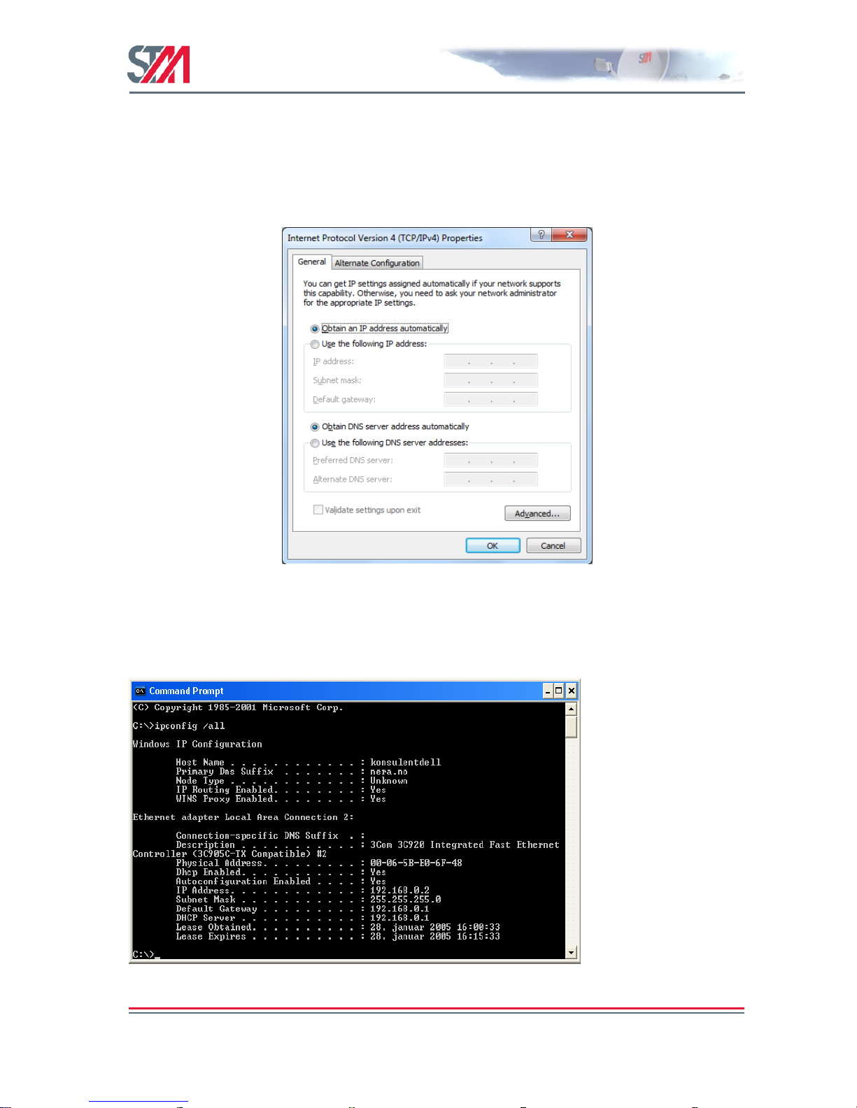
4.1.1 Dynamic IP Configuration of PCs Connected to the VSAT LAN
By default, the DHCP server in the SatLink VSAT is enabled, and when the VSAT is powered on, all PCs
connected to the VSAT LAN can automatically retrieve their IP configuration from the DHCP server. The
user should verify that the Windows clients are configured to obtain an IP address and DNS server
address automatically. Figure 14 shows the correct Windows 7 configuration when the DHCP server is
enabled in the VSAT.
Figure 14: Windows 7 TCP/IP Setting when DHCP Server is Enabled in the VSAT
From an MS-DOS window, the user may type ipconfig /all command to verify that the computer has
received correct configuration parameters from the DHCP server, such as IP address, subnet mask, default
Gateway, DNS servers, and lease time.
Figure 15: ipconfig /all Printout from an MS-DOS Window
Page 20

SatLink VSAT User Guide
Publication no. 101557
Rev 14.1.1-2
Copyright 2006-2012 – STM Group, Inc.
Page 19 (182)
4.1.2 Static IP Configuration of PCs Connected to the VSAT LAN
When the DHCP server in the SatLink VSAT is disabled, all PCs attached to the VSAT LAN must be
configured with static IP addresses that are within the address range of the VSAT subnet. The IP
configuration parameters to use for PCs connected to the VSAT LAN are supplied from the system
operator or service provider. Configure the IP address, Subnet mask, Default gateway, Preferred DNS
server, and, optionally, the Alternate DNS server as shown in Figure 16.
Ensure that the actual IP addresses supplied by the system operator/service provider are
configured and not the IP addresses in the example figure.
Figure 16: Windows 7 TCP/IP Setting when DHCP Server is Disabled in the VSAT
Example:
A host may have the following configuration: IP address 10.201.0.10, Subnet mask 255.255.255.0 and
default gateway 102.201.0.9, where the IP address of the default gateway should be the IP address of the
VSAT LAN interface.
4.2 Windows XP TCP/IP Configuration
Verify that the TCP/IP configuration is correct for PCs connected to the LAN you plan to use for your
SatLink VSAT. Click on the Start button in Windows, click Control Panel and then open Network
Connections. Right-click on the relevant Local Area Connection and select Properties. A new window
showing the Network Connection Properties will pop up. In the General submenu of this window, scroll
down, select Internet Protocol (TCP/IP) and then click the Properties button shown in Figure 17. Then
configure the PC client to obtain the IP address automatically from the VSAT IDU (section 4.1.1 ) or
configure the PC with a static IP address (section 4.1.2).
Page 21

SatLink VSAT User Guide
Publication no. 101557
Rev 14.1.1-2
Copyright 2006-2012 – STM Group, Inc.
Page 20 (182)
Figure 17: Windows XP Menu for Configuring the Client TCP/IP Configuration.
Note: The procedure for Dynamic and Static IP configuration of PCs connected to the VSAT LAN using
Windows XP are the same as described in section 4.1.1 and section 4.1.2, respectively.
Page 22

SatLink VSAT User Guide
Publication no. 101557
Rev 14.1.1-2
Copyright 2006-2012 – STM Group, Inc.
Page 21 (182)
5. Using the SatLink VSAT Web Interface
The SatLink VSAT Web interface supports managing the most common configuration parameters and
viewing the status of the VSAT. The web browser currently supported is Microsoft Internet Explorer, but
other browsers, like Firefox and Opera, typically work fine as well. The functions available via the web
interface are:
Configuring the most commonly used satellite interface parameters
Configuring the most commonly used IP parameters
Return Link line-up procedure
Viewing status information for the satellite interface
Viewing traffic statistics
Viewing device information
Viewing status of the DHCP server
Viewing Event log information
Advanced functions, such as adding SW licenses, configuring GRE tunnels, downloading software
updates manually, configuring automatic software updates, configuring system information, adding users
and changing a user's password, configuring SNMP access, adding manual IP routes, etc., are only
available from the CLI via Telnet or the RS-232 port.
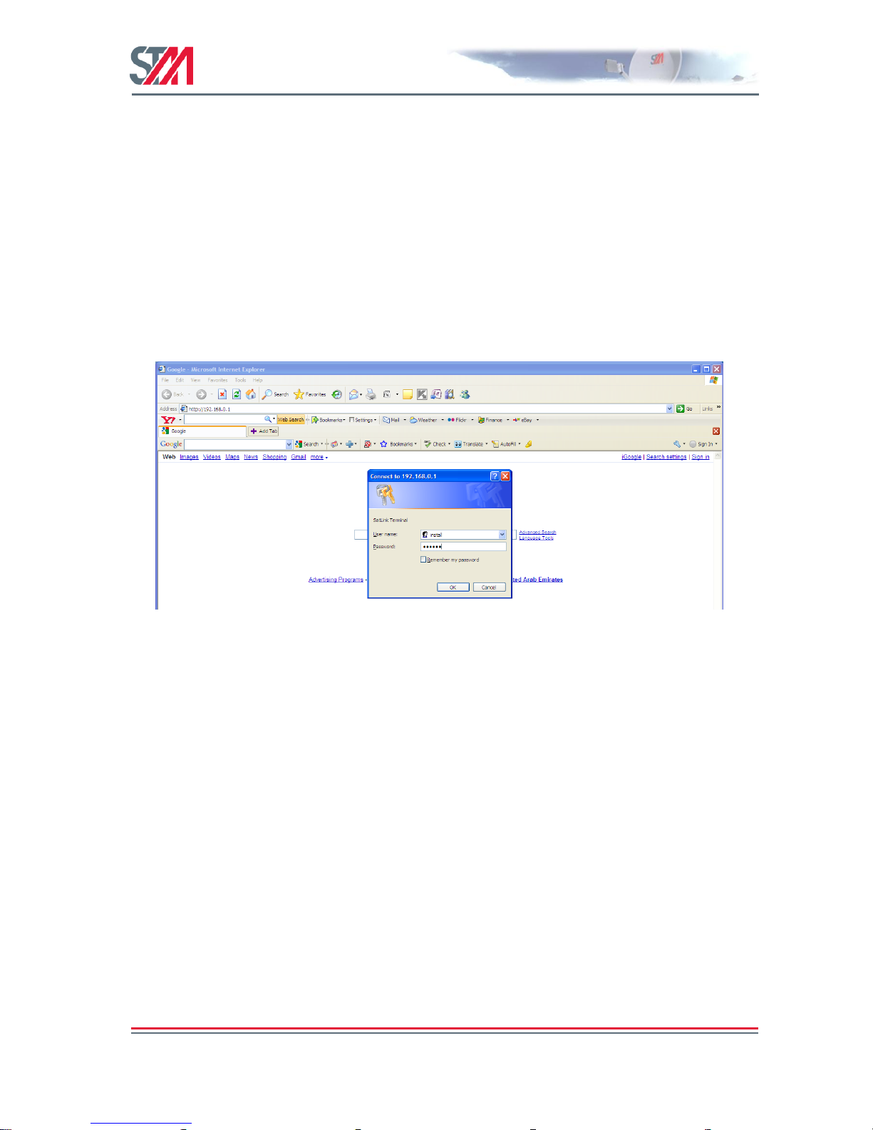
To manage the SatLink VSAT via the web interface, start the web browser and type in the IP address of
the VSAT in the address field as shown in Figure 18. The factory default IP address of the SatLink VSAT
is 192.168.0.1. Use the VSAT‘s Satellite Interface (DVB) IP address when connecting to the VSAT over
the satellite link (from the Hub), and the VSAT‘s LAN (Ethernet) IP address when connecting to the
VSAT from the local LAN. Then enter the username and password to log on to the VSAT.
Figure 18: Connecting to the Web Interface
Page 23
SatLink VSAT User Guide
Publication no. 101557
Rev 14.1.1-2
Copyright 2006-2012 – STM Group, Inc.
Page 22 (182)
6. SatLink VSAT Configuration and Line-up Using the Web
Interface
Follow all the procedures mentioned below when installing the SatLink VSAT and lining up the ODU
using the Web interface. Please see section 7 for SatLink VSAT status monitoring using the web
interface.
6.1 Log On to the VSAT Web Interface
1) Start the web browser and type in the IP address of the VSAT in the address field.
2) Login with username install and factory default password dvbrcs. Click the OK button.
Username: install
Password: dvbrcs
Figure 19: Log on Page
6.2 Configuring VSAT Parameters Required to Log on to the Hub
The SatLink VSAT Web interface is used to configure a number of parameters before the VSAT can
acquire the Forward Link and communicate with the Hub via the satellite connection. A default
configuration specifying most of these parameters is pre-loaded on each VSAT, either in the factory or by
the service provider before installation. The following configuration parameters are typically to be
configured using the VSAT Web interface:
DVB-S2 Reception parameters
VSAT GPS Position
Other parameters are typically configured automatically from the Hub when the VSAT logs on for the
first time. When ODUs other than the SatLink 403x transceiver are used or if the Hub operator does not
use automatic VSAT configuration, then additional VSAT parameters might have to be configured during
installation.
Page 24

SatLink VSAT User Guide
Publication no. 101557
Rev 14.1.1-2
Copyright 2006-2012 – STM Group, Inc.
Page 23 (182)
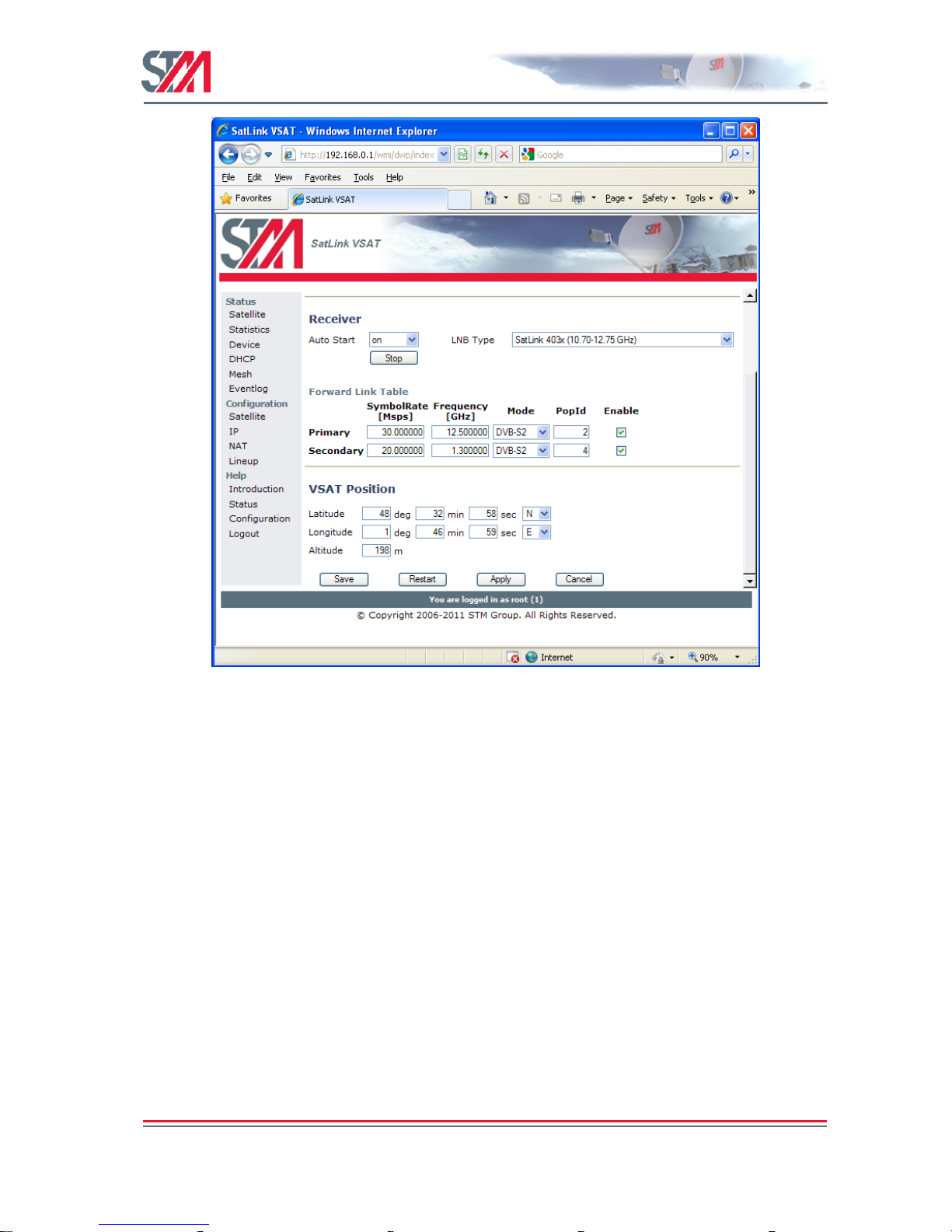
6.2.1 Receiver Parameter Configuration
The VSAT is normally pre-configured to be used together with the SatLink 403x transceiver. But it is
possible to configure the VSAT to operate together with transceivers other than the SatLink 403x. The list
of LNBs that can be used with the VSAT are listed in Table 11
1) Click on the Configuration Satellite option in the SatLink VSAT home page.
Figure 20: Configuring Receiver Parameters for Fixed VSAT
Page 25

SatLink VSAT User Guide
Publication no. 101557
Rev 14.1.1-2
Copyright 2006-2012 – STM Group, Inc.
Page 24 (182)
2) Configure the Receiver parameters as shown in the following table:
Parameter
Description
Auto Start
On
Off
Specific for the receiver. When set to "On" the VSAT will automatically acquire the
Forward Link. It is recommended to always set this to ―On‖ for normal operation. Please
always restart the VSAT after saving configuration when having set auto start to ―On‖.
LNB Type
Specifies the LNB type with which the VSAT is configured.
Entry
The web interface allows the configuration of two Forward Link entries for fixed
VSATs:
Primary: corresponds to ―Index 0‖ of CLI configuration
Secondary: corresponds to ―Index 1‖ of CLI configuration
The primary entry has higher priority than the secondary entry so the Forward Link
search will start with the primary entry.
If the VSAT has a ―Mobile‖ license the web interface allows the configuration of up to
10 Forward Link entries with up to 10 different priorities [0 – 9].
Symbol Rate (Msps)
The Forward Link symbol rate in Msps.
Frequency (GHz)
Forward Link frequency [kHz].
Mode
Enter the valid modes:
DVB-S
DVB-S2
PopId
Population ID to use for Forward Link acquisition. The VSAT will select
which group in the DVB-RCS system it belongs to based on the configured population
ID. The population ID to be used is assigned by the Hub Operator.
Enable
Enable the table entry.
Page 26

SatLink VSAT User Guide
Publication no. 101557
Rev 14.1.1-2
Copyright 2006-2012 – STM Group, Inc.
Page 25 (182)
3) Click the Save button to save the configuration.
4) Click Start button to start the receiver manually (Only required with Autostart mode ―off‖).
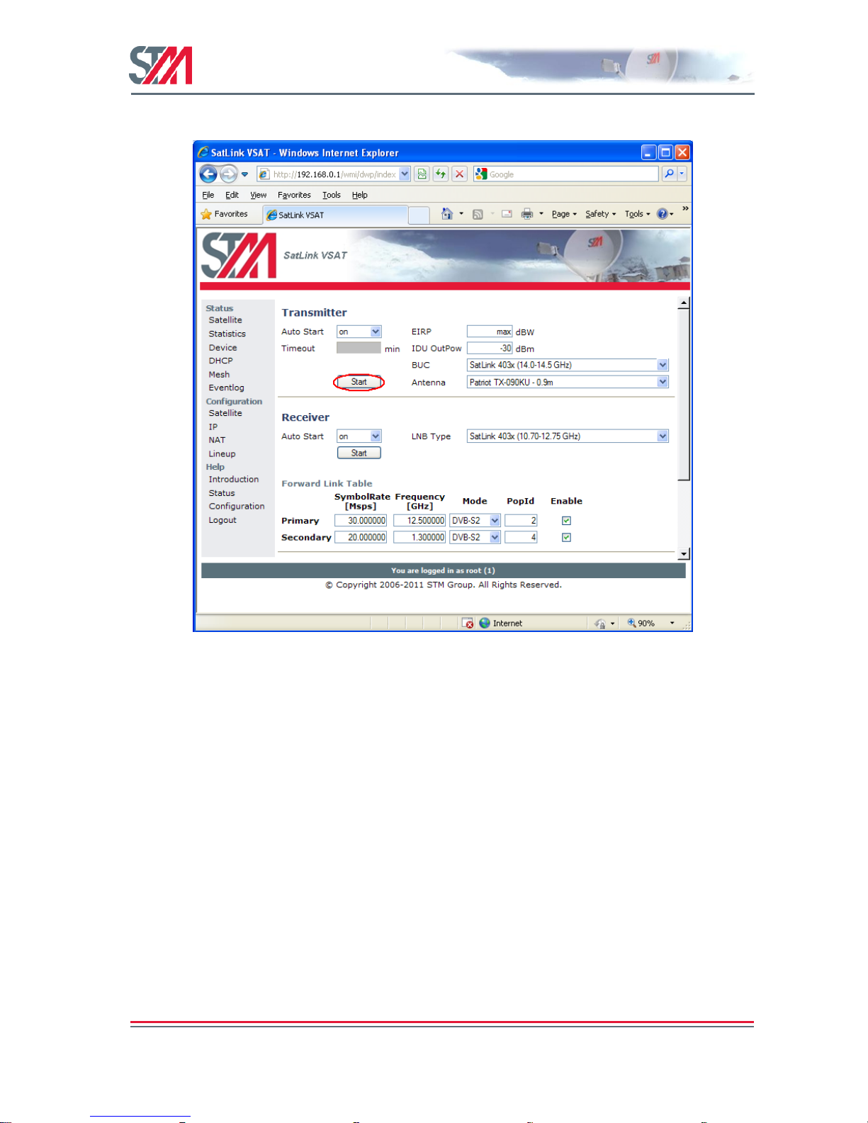
6.2.2 Transmitter Parameter Configuration
The VSAT is normally pre-configured to be used together with the SatLink 403x transceiver. But it is
possible to configure the VSAT to operate together with transmitters other than the SatLink 403x. The
valid ODU transmitters (BUC) used with the VSAT are listed in Table 9.
1) Click on the Configuration Satellite option in the SatLink VSAT home page.
Figure 21: Configuring Transmitter Parameters
Page 27

SatLink VSAT User Guide
Publication no. 101557
Rev 14.1.1-2
Copyright 2006-2012 – STM Group, Inc.
Page 26 (182)
2) Configure the Transmitter parameters as shown in the following table.
Parameter
Description
Auto Start
ON
Off
Traffic
Specific for the transmitter. When set to "traffic", the VSAT will log on to the Hub when
it has traffic to send. After a configurable time (given by Timeout) without any traffic to
send, the VSAT will automatically log off.
EIRP (dBW)
Specifies the emitted power level. Only used for a SatLink 403x ODU and not relevant
for a 3rd party BUC.
Timeout (min)
Idle time before the VSAT automatically logs off when the Autostart mode is set to
"traffic".
IDU OutPow (dBm)
Only used for 3rd party BUCs, as the IDU output power is set automatically when using
a SatLink 403x ODU.
BUC
Specifies the BUC type or transceiver type with which the VSAT is equipped. The valid
ODU transmitters (BUCs) are listed in Table 9.
Antenna
Specifies the antenna type with which the VSAT is equipped. The correct antenna type is
required to correctly compute EIRP used for the automatic power calibration of the
SatLink 403x transceiver. The valid ODU receivers (LNB) are listed in Table 11.
If the ODU transmitter type or LNB type has been changed, the VSAT must be restarted to
activate the new configuration (press the Restart button after saving the configuration).
3) Click the Save button to save the configuration.
4) Click Start button to start the transmitter manually (only required with Autostart mode ―off‖).
6.2.3 VSAT Positioning
The Operator must specify the geographical position of the VSAT to enable the VSAT to log on to the
network. In order to calculate the delay to the satellite correctly for the logon burst, the VSAT must be
configured with its own geographical position. Find the position of the location where installing the
VSAT using a standard GPS.
The VSAT position is entered in the below format:
degrees, minutes, seconds, and direction
Page 28

SatLink VSAT User Guide
Publication no. 101557
Rev 14.1.1-2
Copyright 2006-2012 – STM Group, Inc.
Page 27 (182)
1) Click on the Configuration Satellite option in the SatLink VSAT home page.
Figure 22: VSAT Positioning
2) Configure the VSAT positioning parameters as shown in the following table.
Parameter
Description
Latitude
Enter the latitude (deg, min, sec and direction).
Longitude
Enter the longitude (deg, min, sec and direction)
Altitude
Enter the altitude (meters)
3) Click the Save button to save the configuration.
Page 29

SatLink VSAT User Guide
Publication no. 101557
Rev 14.1.1-2
Copyright 2006-2012 – STM Group, Inc.
Page 28 (182)
6.2.4 IP Address Configuration
1) The VSAT web interface is used to configure the IP addresses and netmasks of the VSAT's LAN,
Management and Virtual (Vir1-eth0) interfaces. The Web interface is also used for LAN DHCP
server, DNS, NAT, and PEP configuration.
Click on the Configuration IP option in the SatLink VSAT home page.
Figure 23: IP Configuration – LAN, Management, and Virtual Interfaces
2) Enter the valid IP address and Netmask for the LAN, Management, and Virtual (Vir1-eth0) interfaces.
3) Enable / Disable the DHCP server.
The DHCP server can be enabled only for one interface (LAN or Virtual).
When enabled, the DHCP server will automatically allocate IP addresses in the VSAT LAN (or
Virtual) Interface subnet except the VSAT's own IP LAN (or Virtual) address and addresses excluded
manually.
4) Set the lease time for an IP address allocated to a host on the LAN (or Virtual) subnet.
5) Specify the number of IP addresses to be excluded from the available range of addresses defined by
the VSAT LAN (or Virtual) subnet. The excluded range of IP addresses will be the upper range of the
LAN (or Virtual) subnet.
6) Enter the IP address for the primary and secondary DNS servers to be used by the hosts on the VSAT
LAN (or Virtual) subnet.
Page 30

SatLink VSAT User Guide
Publication no. 101557
Rev 14.1.1-2
Copyright 2006-2012 – STM Group, Inc.
Page 29 (182)
7) Enable / Disable NAT (dynamic NAPT) for the VSAT.
When enabled, enter the NAT Global Address.
8) Enable / Disable the TCP and HTTP acceleration.
9) Click the Save button to save the configuration.
6.3 NAT Configuration using the Web Interface
Set up the NAT Configuration as shown below.
Figure 24: NAT Configuration
Parameter
Description
Global Address
Enter Global Address
Local Address
Enter Local Address
Global Port
Enter Global Port nr.
Local Port
Enter Local Port nr.
Port Range
Enter wanted Port Range.
6.4 Line-up Using the Web Interface
Perform antenna and ODU installation and alignment as described in Appendix F and the initial
parameter configuration described in section 6.2 before proceeding with the line-up procedures described
here.
6.4.1 Antenna Line-up
Set the alignment of the antenna to optimize the receive SNR. The RX SNR displayed in the graph on the
line-up page should appear as a green bar to ensure a stable reception of the Forward Link signal. If the
bar is yellow, the signal can be received correctly with low link margin and if the bar is red, the signal
Page 31

SatLink VSAT User Guide
Publication no. 101557
Rev 14.1.1-2
Copyright 2006-2012 – STM Group, Inc.
Page 30 (182)
level is too low for error free reception. The RX SNR displayed in the graph on the line-up page appears
as a green bar when the RX SNR value is greater than 7.5 dB, yellow if the RX SNR value is 6 - 7.5 dB,
and red if the RX SNR value is 0-6 dB.
Figure 25: RX SNR Graph
Please see section 9.3 for details of which SNR values are required for different Forward Link
configurations.
6.4.2 TX Power Calibration
This section describes how to calibrate the TX output power when using the SatLink 4033/4035 transceiver. See
Appendix I for a description of how to perform TX power calibration for other transmitters (BUCs).
TX power level calibration and Return Link acquisition shall only be performed if the Forward
Link has been acquired and is operating properly.
1. Ensure that the VSAT configuration procedure in section 6.2 has been performed.
2. Ensure that the VSAT receiver is started and the Forward Link is acquired.
3. Ensure that the VSAT transmitter is turned off and the TX cable from the VSAT to the ODU is
connected.
4. Click the Lineup option in VSAT home page and configure the transmit EIRP level of the VSAT.
Page 32

SatLink VSAT User Guide
Publication no. 101557
Rev 14.1.1-2
Copyright 2006-2012 – STM Group, Inc.
Page 31 (182)
The VSAT can either be configured to transmit at maximum level or alternatively the desired EIRP
level can be set to a given level for use in a system where the power level received at the satellite is
aligned for all VSATs.
Figure 26: TX Power Calibration
5. The CW frequency to be used for measurements during the calibration procedure is obtained from the
service provider or satellite operator.
6. Contact the satellite operator / control center to clarify the line-up procedures for transmission power
calibration and fine adjustment and verification of polarization of the VSAT.
7. Push the Start Calibration button on the Line-up page to start automatic transmitter power calibration.
During this calibration, the transmit EIRP level is detected and the IDU output level is automatically
adjusted to the level required for transmitting with the configured EIRP level. Hence, no manual
configuration of the IDU output power level or cable attenuation is required.
6.4.3 3rd Party BUC Line-up
When using 3rd party BUCs (i.e., other than the SatLink 403x transceiver), the IDU output power has to
be manually adjusted during line-up by use of feedback from the system operator. Beware of the risk of
setting the IDU output level too high as a consequence of the antenna pointing not being sufficiently
accurate.
Page 33

SatLink VSAT User Guide
Publication no. 101557
Rev 14.1.1-2
Copyright 2006-2012 – STM Group, Inc.
Page 32 (182)
1. Log on to the VSAT Web interface and click Lineup option in VSAT home page.
2. Ensure that the initial IDU output power level is set to a low value (-30 dBm is recommended).
Figure 27: CW Transmission
3. Click the CW On button on the Line-up page to initiate the CW transmission. Start the CW
transmission only after the permission is granted by the system operator.
4. Adjust the IDU output power in small steps (never more than 5 dB) based on feedback from the
system operator.
Page 34

SatLink VSAT User Guide
Publication no. 101557
Rev 14.1.1-2
Copyright 2006-2012 – STM Group, Inc.
Page 33 (182)
6.4.4 Fine Adjustment of Antenna Pointing and Polarization
After the initial IDU output power level has been found, the pointing and polarization of the antenna
should be finely adjusted based on feedback from the system operator.
1. Fine-tune the pointing and polarization of the antenna based on the feedback from the system
operator.
2. After the fine adjustment of the antenna, the received signal level should again be verified by
consulting the system operator and the IDU output power level should be adjusted as necessary.
3. Click the Save button on the satellite configuration page to save the configuration.
6.5 Test of Connection to Hub
After the line-up procedure in section 9.3 (or alternatively, Appendix I.1) has been successfully
completed, the VSAT is ready to log on to the Hub.
The VSAT is only allowed to log on to the network if its DVB MAC address is registered at the Hub.
Registration of the VSAT‘s MAC address at the Hub is a network operator's responsibility. The DVB
MAC address of the VSAT can be found under the Device option on the SatLink web interface home
page or it can be found on the label underneath the VSAT chassis. The MAC address is also shown on the
CLI message displayed during the boot procedure of the VSAT.
Example:
# device show
System Information:
Name : SatLink 2000
Location : UAE
Contact : STM UAE
System Up time : 0 days, 00:01:18
CPU Load : 4%
System time (UTC) : not set, TDT not received
Broadcast Message : not set
HW:
Model : SatLink 2000
HW ID : 120033
Main board ID : 120026 R3.3
MAC addresses:
Ethernet (LAN) : 00:20:0e:10:35:34
Satellite (DVB) : 00:20:0e:10:35:34
Then do the following:
1) If the receiver is not already on, Click Configuration on the SatLink VSAT home page and start the
receiver by clicking on the Start button to acquire the Forward Link.
Page 35
SatLink VSAT User Guide
Publication no. 101557
Rev 14.1.1-2
Copyright 2006-2012 – STM Group, Inc.
Page 34 (182)
Figure 28: Receiver Configuration
Page 36
SatLink VSAT User Guide
Publication no. 101557
Rev 14.1.1-2
Copyright 2006-2012 – STM Group, Inc.
Page 35 (182)
2) Start the transmitter by clicking on the Start button and log on to the DVB-RCS network.
Figure 29: Transmitter Configuration
3) Click the Save button to save the configuration.
4) To test the connection to the Hub, select Satellite under the Status option on the SatLink web
interface home page. This displays the Satellite Interface Status page.
5) If the proper connection is established to the Hub, the following status will be displayed on the
Satellite Interface Status page:
State : ―Two-way link established‖
Transmitter : ―On‖
Receiver : ―On‖
Page 37

SatLink VSAT User Guide
Publication no. 101557
Rev 14.1.1-2
Copyright 2006-2012 – STM Group, Inc.
Page 36 (182)
Figure 30: Satellite Interface Status
6.6 Prepare the VSAT for Normal Operation
The connection to the Internet over the satellite network should now be tested and found to be working.
The only thing left is then the final configuration to prepare the VSAT for normal operation. The VSAT
must be started and a user must be logged in with a minimum privilege level of 2 (e.g., install user)
before completing the following operations.
1) Click on the Satellite option under Configuration in the SatLink VSAT home page and Configure the
VSAT to automatically start the receiver by setting Auto Start to ―ON‖. The VSAT will automatically
acquire the Forward Link. Setting the RX auto start to ―ON‖ will ensure that the receiver is started
automatically after power failure, link failure, Hub restart, or a software failure, etc., without needing
user intervention.
Page 38
SatLink VSAT User Guide
Publication no. 101557
Rev 14.1.1-2
Copyright 2006-2012 – STM Group, Inc.
Page 37 (182)
Figure 31 : Receiver Auto Start
Page 39

SatLink VSAT User Guide
Publication no. 101557
Rev 14.1.1-2
Copyright 2006-2012 – STM Group, Inc.
Page 38 (182)
2) Configure the VSAT to automatically start the transmitter by setting the Auto Start to ―ON‖.
Setting the TX auto start on will ensure that the transmitter is started automatically after power
failure, link failure, Hub restart, or a software failure, etc., without needing user intervention.
Figure 32 : Transmitter Auto Restart
3) Click the Save button to save the configuration.
Page 40

SatLink VSAT User Guide
Publication no. 101557
Rev 14.1.1-2
Copyright 2006-2012 – STM Group, Inc.
Page 39 (182)
7. Status Monitoring Using the SatLink Web Interface
The SatLink web interface is used to display the status of the SatLink VSAT. An operator can view the
status information of the satellite interface, packet and burst statistics, device information, the status of the
DHCP server, and the status of mesh and terminal burst receiver.
7.1 Satellite Interface Status
The satellite option provides an overview of the status on the satellite interface, such as the state,
transmitter and receiver. Select the Satellite option under Status on the SatLink web interface home page
to open the Satellite Interface Status page.
Figure 33: Satellite Receiver Status
Parameter
Description
State
Specifies the state of the satellite (DVB) interface. During normal operation, it reads ―Two-way link
established‖.
Transmitter
This determines the transmitter status. During normal operation, it reads ―On‖.
Receiver
This specifies the receiver status. During normal operation, it reads ―On‖.
Page 41

SatLink VSAT User Guide
Publication no. 101557
Rev 14.1.1-2
Copyright 2006-2012 – STM Group, Inc.
Page 40 (182)
Satellite Receiver Status
The satellite receiver status option displays the detailed view of the receiver status. The operator can view
the receiver state, network ID, network name, mode, FEC rate, modulation, roll-off, frame length, pilot,
transmission mode, error rate, frequency, SNR, symbol rate, and Rx Input power of the satellite receiver.
Parameter
Description
State
Specifies the receiver state. During normal operation it reads "Forward Link up".
Network ID
This determines the DVB network ID of the Forward Link.
Network Name
The DVB network name of the Forward Link.
Mode
This specifies whether the Forward Link is a DVB-S or DVB-S2 carrier.
FEC rate
Detected FEC rate on the Forward Link.
Modulation
Specifies the detected modulation of the Forward Link.
Roll-off
Detected Roll-off factor of the Forward Link.
Frame length
Long or short frame
Pilot
Off or On
Transmission mode
CCM or ACM
Error-rate
The number of errors detected by the Viterbi decoder during a fixed time period.
Frequency
The measured receive frequency for the Forward Link.
SNR
This determines the current measured signal to noise ratio for the received Forward Link
signal.
Symbol rate
The measured symbol rate for the Forward Link.
Rx Input power
Satellite Transmitter Status
The satellite transmitter status option displays the detailed view of the receiver status. The operator can
view the transmitter state, IDU output power, ODU output power, EIRP, Frequency offset, Timing offset,
Capacity and SNR of the satellite transmitter.
Page 42

SatLink VSAT User Guide
Publication no. 101557
Rev 14.1.1-2
Copyright 2006-2012 – STM Group, Inc.
Page 41 (182)
Figure 34: Satellite Transmitter Status
Parameter
Description
State
Specifies the transmitter state. During normal operation it reads "On".
IDU Output Power
This specifies the current power level transmitted by the IDU.
ODU Output Power
Determines the current power level transmitted by the ODU.
EIRP
This parameter specifies the current EIRP transmitted by the VSAT. Note that the value
displayed will only be correct if the antenna is correctly specified on the satellite
configuration page.
Frequency Corr
Current frequency offset of the Return Link transmitter.
Timing Corr
Current timing offset of the Return Link transmitter.
Capacity
Shows the Return Link bandwidth currently being allocated to the Return Link transmitter.
SNR
Shows the SNR of the transmitted Return Link signal as received at the other end of the link.
7.2 Statistics
The statistic option displays the status for IP packets statistics, Multi field classifier statistics, Forward
Link statistics, and Return Link statistics. Select the Statistics option on the SatLink web interface home
page.
IP Packets Statistics
The IP Packets table gives IP packet statistics on the VSATs interfaces. The statistics are collected on two
interfaces: LAN (Ethernet) and DVB (Satellite). For each interface, the table contains the number of IP
packets and the number of bytes that have been received, transmitted, and discarded at the given interface.
Page 43

SatLink VSAT User Guide
Publication no. 101557
Rev 14.1.1-2
Copyright 2006-2012 – STM Group, Inc.
Page 42 (182)
Figure 35: SatLink VSAT Statistics
Multi-Field Classifier Statistics
The Multi-Field Classifier table displays information about the configuration of the MFC table. A multifield classifier is used by the VSAT to determine the QoS group an IP packet to be transmitted on the
Return Link belongs to by performing a look-up in a classification table. The MFC is also used to
determine the handling of TCP connections by the Performance Enhancing Proxy client (TCP PEP).
Forward Link Statistics
The Forward Link table displays the statistics for the satellite Forward Link (receiver). Traffic on the
Forward Link is arranged on different PIDs (Packet Identifier); for each PID, there is one row in the table.
Return Link Statistics
The Return Link table displays the statistics for the satellite Return Link (transmitter). The Return Link
transmission is segmented in bursts. The table shows how many bursts have been sent since logon for the
following burst types:
Page 44

SatLink VSAT User Guide
Publication no. 101557
Rev 14.1.1-2
Copyright 2006-2012 – STM Group, Inc.
Page 43 (182)
7.3 Device Status
The Device option in the SatLink web interface displays the device status information as displayed in the
following figure and table. Select the Device option on the SatLink web interface home page to open the
Device status page.
Figure 36: Device Status
Parameter
Description
Model
VSAT hardware model
Software version
This specifies the version number (including build number) of the application software
currently running.
LAN MAC
address
MAC address of the LAN (Ethernet) interface of the VSAT.
DVB MAC
address
MAC address of the DVB (satellite) interface of the VSAT.
System UP Time
Time elapsed since last VSAT boot.
System time
UTC time (only displayed if UTC time is broadcasted by the Gateway).
CPU load
Current load of VSAT CPU.
System name
Specifies the Name of VSAT. This and the following two parameters are MIB objects in the
MIB-II systems group and can be set via SNMP or from the CLI using the ―device‖ menu.
System contact
Name of the contact person and/or company, who is responsible for this VSAT.
System location
This determines the Location of the VSAT.
ODU Serial
Number
Specifies the serial number of the ODU for VSATs configured with a SatLink 403x ODU.
ODU HW
Version
Specifies the HW revision for VSATs configured with a SatLink 403x ODU.
Page 45

SatLink VSAT User Guide
Publication no. 101557
Rev 14.1.1-2
Copyright 2006-2012 – STM Group, Inc.
Page 44 (182)
7.4 DHCP Server Status
The DHCP option in the SatLink web interface provides information about the status of the DHCP server
and the DHCP client table, such as DHCP status, Server IP address, Server IP address range, Number of
IP addresses excluded, Lease time and Excluded IP address range. Select the DHCP option in the SatLink
web interface home page to open the DHCP Server Status page.
Figure 37: DHCP Server Status
Parameter
Description
Server status
Determines whether the DHCP server is enabled or disabled.
Server IP address
The IP address of the DHCP server.
Server IP address
range
The pool of IP addresses that the DHCP server can lease to the DHCP clients.
Number of IP
addresses excluded
The number of IP addresses that are not allocated from the server's IP address range. These
addresses are typically used for hosts on the VSATs LAN that require static IP addresses.
Excluded IP address
range
It is a subrange of the server IP address range, containing IP addresses that should not be
allocated by the DHCP server. This range is an interval; it is defined with the help of the
starting IP address and the ending IP address for the excluded range.
Lease time
Time period for which an IP address is leased to a DHCP client
The DHCP client table shows information about the IP addresses that are currently leased from the DHCP
server: host name, IP address, MAC address, and lease time expiration. The DHCP server will only lease
IP addresses to the LAN hosts for 15 minutes until it has acquired the network time. The DHCP server
will apply the configured lease time when the network time is acquired.
Page 46

SatLink VSAT User Guide
Publication no. 101557
Rev 14.1.1-2
Copyright 2006-2012 – STM Group, Inc.
Page 45 (182)
8. Using the Command Line Interface of the SatLink VSAT
The command line interface can be accessed via either Telnet or the RS-232 port for management of the
SatLink VSAT IDU, as well as for showing status and reports.
8.1 CLI User Access Rights
Four levels of CLI user access rights are available for differentiating user privileges:
Level 2: installer
Level 3-5: end users
When shipped from the factory, one user is pre-configured in the SatLink VSAT:
User name
Factory default password
Privilege level
install
dvbrcs
2
If the login prompt is not displayed when accessing the CLI via RS-232, type <ENTER>. The login
prompt, Login: should then be displayed. Then login with the install user:
Login: install
Password: dvbrcs
When the command prompt is displayed, you will now have access to the CLI with privilege level 2.
New users may be added with the CLI command user add, existing users deleted with the CLI
command user del, and the password of the current user or users with lower privilege levels can be
changed with the CLI command user passwd. To list all defined users with lower privilege level than
the user currently logged in, use the CLI command user show. Type ? user to get further help on the
user commands.
For security reasons, we recommend that you change the factory set password to your own personal one.
8.2 Online Help
In the CLI, a list of available commands can be displayed by typing ? <ENTER> (question mark and the
ENTER key). The CLI command groups will then be shown:
Example:
# ?
? : ? <submenu|command>
device : Device configuration
dvb : DVB interface configuration
eth : Ethernet configuration
ip : IP configuration
log : Event log
misc : Miscellaneous commands
odu : ODU configuration
sw : Software upgrade & licenses
user : User configuration
Page 47

SatLink VSAT User Guide
Publication no. 101557
Rev 14.1.1-2
Copyright 2006-2012 – STM Group, Inc.
Page 46 (182)
To display the available commands within one sub-menu, type ? <sub-menu>.
Example:
?
? ip
show : ip show [-mcast]
tracert : ip tracert [<options>] <ipaddr>
set : ip set <ifnum> {<ipaddr> <mask>}|nonum
addroute : ip addroute <destaddr> <netmask> [<next hop>] [<if>]
delroute : ip delroute <destaddr> [<netmask> [<next hop> [<if>]]]
intf : Interface configuration
gre : GRE Configuration
dhcp : DHCP configuration
dns : DNS configuration
nat : NAT configuration
qos : IP QOS configuration
mfc : IP Multi Field Classifyer (MFC) configuration
lac : IP Link Access Control (RAC) configuration
pep : PEP configuration
hc : Header compression configuration and status
udpsend : ip udpsend <options>
udprecv : ip udprecv <options>
To get further help on a specific CLI command, type ? <cmd>.
Example:
# ? ip set
USAGE:
ip set <ifnum> <ipaddr> <mask> |nonum
ifnum Interface number (1=LAN, 3=Satellite)
ipaddr IP address for the interface
mask Netmask for the interface
nonum Use nonum instead of ipaddr and mask to remove the IP address
Set the IP address and subnet mask for the specified interface
If the interface is Virtual-VLAN, then the IP should be from the subnet of its
source VLAN.
If the interface is a VLAN, then its corresponding virtual VLANs IP will be
cleared.
Example:
ip set 1 10.10.1.1 255.255.255.248 will set the LAN IP address to
10.10.1.1 and the LAN netmask to
255.255.255.248
See also:
ip show, ip addroute, ip delroute
8.3 Logging of Events
The SatLink VSAT logs certain events to a log stored in the RAM. See Appendix K.5 for a list of the
different events and required actions. Use the CLI command log show to show the log in memory.
The events are divided into four different severity levels:
0. Minor
1. Normal
2. Major
3. Critical
Page 48

SatLink VSAT User Guide
Publication no. 101557
Rev 14.1.1-2
Copyright 2006-2012 – STM Group, Inc.
Page 47 (182)
Events with severity level Major will normally cause disruption in the data transfer, while events with
severity level Critical normally will require user intervention in order to restore the data communication
with the DVB-RCS Hub.
To have access to the log of events after the VSAT software has been rebooted, the event above a
specified severity level can be logged to file. Use the CLI command log file to enable logging of
events to file, set the minimum severity level of events that shall be logged to file, and set the maximum
size for the logfile. By default, Major and Critical events are logged to file.
8.4 CLI Command Summary
The available CLI commands are listed below.
CLI commands
Available
in Boot
SW
Available in
Application
SW
User
Privilege
Level
? [sub-menu] [cmd]
x x 5
del <filename>
x x 2
ren <filename1> <filename2>
x x 2
mv <filename1> <filename2>
type <filename>
setrows <row-number>
x x 2
dir [ext]
x x 5
type <filename>
x x 5
dload <filename> <ipaddr> [<localname>]
x x 2
upload <filename> <ipaddr> [<remotename>]
x x 3
ping {<ipaddr> [<options>]}|-stop|<enablemonitor|disablemonitor
x x 5
exit x x
5
logout x x
5
restart x x
3
save config
arp flush <all | static | dynamic>
arp show
x
x
x
3
3
5
device snmp show
x 1
device snmp community <name> <ro|rw>
[<ipaddr> <mask>]
x 1
device snmp delcommunity <name>
x 1
device manager show
x 1
device manager add <func> <if> [<ip> <mask>]
x 1
device manager del <func> <if> [<ip> <mask>]
device manager httpport <port>
x 1
device name <name>
x 2
device contact <contact>
x 2
device location <location>
x 2
device show [-dvbs2]
x 5
device telnet show [-session id]
x 5
device telnet disconnect <session id>
x 1
dvb atmmode <mode>
x 2
dvb hdrcomp <mode> |-show
dvb cr capacity <crClass> <CRA> <RBDCMax>
<VBDCMax>
dvb cr timeout <RBDCtimeout VBDCtimeout>
dvb cr interval [-vbdc <interval>]
dvb cr show [-timeout|-interval|-capacity]
x 2
Page 49

SatLink VSAT User Guide
Publication no. 101557
Rev 14.1.1-2
Copyright 2006-2012 – STM Group, Inc.
Page 48 (182)
CLI commands
Available
in Boot
SW
Available in
Application
SW
User
Privilege
Level
dvb brx show [-stats]
dvb brx stats [enable | disable]
dvb brx offset <freq>
dvb brx cscLog <value>
dvb mesh show [-links| -config| -routes| stat]
dvb mesh enable
dvb mesh disable
dvb tx autostart <on|off|traffic> [<timeout>]
x 2
dvb tx calibrate [<freq> [<timeout>]]
x 2
dvb tx cw <on|off> [-notrack] [<pow> [<freq>
[<timeout>]]]
x 2
dvb tx cwfreq <freq>
x 2
dvb tx eirp <eirp>
x 2
dvb tx logoff
x 3
dvb tx logon
x 3
dvb tx outpow [-max] <pow>
x 2
dvb tx show [-burst|-capacity|-queue|-ts]
dvb tx pause -dc <on|off> [<timeout>]
x 5
dvb tx start
x 3
dvb tx stop
x 3
dvb rx autostart <on|off>
x 2
dvb rx start
x 3
dvb rx stop
x 3
dvb rx fwdlink <idx> <pri> [-del|-disable|enable][<symbrate> [<freq> [<mode>
[<popid>]]]]
x 3
dvb rx phy [-internal | -satlink100|satlink110]
x 2
dvb rx show [-pid | -cnt]
x 5
dvb rx watchdog <min>[<restartOnMissingTable>]
x 2
dvb rx tablecache <on|off> [<tunerRetryTime>]
x 2
dvb pos lat <deg> <min> <mindec> <dir>
x 2
dvb pos long <deg> <min> <mindec> <dir>
x 2
dvb pos alt <height>
x 2
dvb pos delayburst <tics|nera|satlabs|| -s2ccm
<satlabs | satlink> >
x 2
dvb pos show
x 5
dvb mesh show <-links| -config| -routes| stat>
X
dvb mesh enable
x
dvb mesh disable
x
eth mode <mode>1
x 3
eth vlan [-del|-allow|-block] <id>
x 2
eth primap [-del] <pri> <qos>
x 2
eth show
x 5
ip addroute <destaddr> <netmask> <next hop>
<ifnum>
x x 2
ip delroute <destaddr> [<netmask> [<next hop>
x x 2
1
CLI command is only available when corresponding SW license key is set
Page 50

SatLink VSAT User Guide
Publication no. 101557
Rev 14.1.1-2
Copyright 2006-2012 – STM Group, Inc.
Page 49 (182)
CLI commands
Available
in Boot
SW
Available in
Application
SW
User
Privilege
Level
[<if>]]]
ip mfc mask <module id> <sub index> <index>
<group> {{+|-} <tag> <tag-parms>}+
x 2
ip mfc show [module id]
x 5
ip qos show
x 5
ip set <ifnum> {<ipaddr> <mask>}|nonum
x x 2
ip show [-mcast]
x x 5
ip dns server <primary> [secondary]
x 2
ip dns flush
x 3
ip dns resolve <domain>
x 3
ip dns show [-cache]
x 5
ip intf add <if>
x 2
ip intf del <if>
x 2
ip intf addroute <ifin> <ifout>
x 2
ip intf delroute <ifin>
x 2
ip nat enable
x 2
ip nat disable
x 2
ip nat global <add|del> <gladdr> [<interface>]
x 3
ip nat static <add|del> <gladdr> [<locaddr>]
x 3
ip nat napt add <gladdr> <globport-first>
[<port-range>] <locaddr> <locport-first>
[<if>] | del <gladdr> <globport-min> [<if>]}
x 3
ip nat <show>
x 5
ip dhcp <enable > [<interface>]
ip dhcp disable
x 3
ip dhcp show
x 5
ip dhcp leasetime <time> [unit]
x 3
ip dhcp exclude <no> [<interface>]
x 3
ip gre add <destaddr> <netmask> <tunnelipaddr>
[<if>]1
x 2
ip gre del <ifnum>
x 2
ip gre show
x 5
ip pep disable [httpa]1
x 2
ip pep enable [redirect|trans|httpa]]1
x 2
ip pep server <pepsrvipadd>1
x 2
ip pep show [-cache]
ip pep flush -cache
x 5
ip pep bypass <-add|-del|-show|-reset> [<URL>]1
x 3
ip pep dynbypass <options>1
x 3
–
ip pep httpmux <options>
ip tracert [<options>] <ipaddr>
ip lac rpf {enable|disable}
ip lac srceqdest {enable|disable}
ip hc rtp [show | enable | disable>] | [comp
<info |stat {cid} | bklist > ]|[decomp <info |
stat {cid} >]
ip udpsend <options>
x 5
ip udprecv <options>
x 5
log file <enable|disable> [<severity>
[<filesize>]]
x 3
log show [<number> |<-all> |<-conf> | [-file
<number>]
x 5
Page 51

SatLink VSAT User Guide
Publication no. 101557
Rev 14.1.1-2
Copyright 2006-2012 – STM Group, Inc.
Page 50 (182)
CLI commands
Available
in Boot
SW
Available in
Application
SW
User
Privilege
Level
odu lnb <type>
x 2
odu txtype <type>
x 2
odu antenna <type>
x 2
odu show [-diseqc]
x 5
sw license <feature> <key>
x 2
sw mcast <value> [<pid>] [<addr>] [<port>]
x 2
sw upgrade [-default] [<filename>
[<tftp-ip-addr>]]
x 2
sw restore
x 2
sw show x
5
user add <username> <passwd> [<userlevel>]
x x 4
user del < username>
x x 4
user passwd [<oldpasswd> |<username>]
<newpasswd>
x x 5
user show
x x 5
Page 52

SatLink VSAT User Guide
Publication no. 101557
Rev 14.1.1-2
Copyright 2006-2012 – STM Group, Inc.
Page 51 (182)
9. SatLink VSAT Configuration and Line-up Using the
Command Line Interface
Follow all the procedures below when installing the SatLink VSAT and lining up the ODU using the
command line interface of the SatLink VSAT.
9.1 Power On and Log On
1) To view the boot processes of the SatLink VSAT, connect a PC to the serial interface and launch a
Terminal Emulator as described in Appendix A. Otherwise, go to step 2.
2) Turn on the power of the SatLink VSAT.
When turning on the SatLink VSAT, the Boot SW is loaded first. A message such as the one below is
displayed on the CLI serial console when the boot SW starts. Telnet is not available until the application
has been started.
Boot-loader
- SW ID 120511, Revision 14.1.0 Build 5
File system initialised
Ethernet Mode (eth0): 100Mbps/Full
Press CTRL+A to abort and enter boot loader
Under normal circumstances, the user should not need to enter the boot-loader and should ignore the
―press return to enter boot-loader‖ message. The DVB-RCS application will load automatically once the
boot SW load has completed. See Appendix J for further details concerning the boot SW. If access to the
boot-loader is required, press return within 10 seconds to display the login-prompt for entering the bootload. After the timer has expired, the DVB-RCS application will be loaded. The message Loading
application will be shown when the application starts to load.
Page 53

SatLink VSAT User Guide
Publication no. 101557
Rev 14.1.1-2
Copyright 2006-2012 – STM Group, Inc.
Page 52 (182)
3) Wait for the application software to be loaded and activated (typically takes 1-1.5 minutes).
The power LED on the front of the SatLink VSAT will blink when the SW is booting and will stay on
when the SW has successfully started. If watching the boot process on the RS-232 output, a printout
similar to this will be displayed when the SW has booted:
Loading application......................
SatLink 2900
- Main board ID 120265, Revision R2.1
- SW ID 120208, Revision 14.1.0 Build 41
File system initialised
Ethernet Interface 1 MAC Address: 00:20:0e:10:44:92
Ethernet Interface 2 MAC Address: 00:20:0e:10:44:93
DVB Interface MAC Address: 00:20:0e:10:44:92
Retrieving configuration....done
When the SatLink VSAT is configured for use with the SatLink 4033/4035 transceiver and the
TX cable is not connected to the ODU, the following error message will be shown when the
SW has booted:
ODU Initialisation failed. Unable to establish DiSEqC communication.
Please check connection to ODU and that the ODU supports
DiSEqC communication
This is normal and just indicates that the VSAT cannot communicate with the transceiver
since the cable is not yet connected.
4) At this point, the Telnet server in the SatLink VSAT is started and a Telnet session can be opened for
managing the VSAT. Local Echo must be enabled in the Telnet Client if the input from the keyboard
shall be displayed. Recommended Telnet clients are Tera Term (see Appendix C), PuTTY2, and the
built-in Telnet client in Windows. Note that Local Echo by default is set to ―off‖ in Windows XP.
Alternatively, HyperTerminal or another terminal emulator connected via the serial interface can be
used (see Appendix A). From this point, the SatLink VSAT can also be managed via the Web
interface and SNMP.
Use the SatLink VSAT‘s Satellite Interface (DVB) IP address when using Telnet over the satellite
link (from the Hub), and the VSAT‘s LAN (Ethernet) IP address when using Telnet from the local
LAN.
When shipped from the factory, the SatLink 1000, 1910, 2000, and 2900 VSAT LAN (Ethernet) IPaddresses are set to 192.168.0.1 and the subnet mask to 255.255.255.0. If the SatLink VSAT LAN
(Ethernet) IP address has been changed from the factory default to an unknown address, one must use
CLI via serial COM port to do the initial configuration.
The SatLink VSAT can handle, at most, three simultaneous Telnet connections, including aborted
connections. The Telnet session will be automatically terminated after 20 minutes of inactivity. If a
Telnet session is refused, this can be due to all three connections being aborted. Please wait until the
timeout has expired and try again.
2
http://www.chiark.greenend.org.uk/~sgtatham/putty/download.html
Page 54

SatLink VSAT User Guide
Publication no. 101557
Rev 14.1.1-2
Copyright 2006-2012 – STM Group, Inc.
Page 53 (182)
5) Login as the administrator user install with the factory default password dvbrcs:
Login: install
Password: dvbrcs
The user must press Enter once to get the login-prompt to display if using the CLI via
serial port. If the input from the keyboard is not displayed when typing the username and
password, check that the Local Echo is enabled in the Telnet client.
6) The SatLink VSAT should now be ready to be configured as described in the following sub-sections.
9.2 Initial Configuration of Parameters
The VSAT must be configured with a number of parameters before the VSAT can acquire the Forward
Link and communicate with the network Hub. A default configuration specifying most of these
parameters is usually pre-loaded on each VSAT, either in the factory or by the service provider before
installation. The parameters that usually need to be configured by the installer are:
Antenna to be used
Forward Link frequency and symbol rate
VSAT population ID
VSAT geographical position
Most SatLink networks enforce automatic configuration of VSAT parameters, like IP
addresses, DHCP server configuration, DNS server, SW licenses, and PEP parameters
when the VSAT logs on to the network for the first time. For manual configuration of
these parameters, refer to Appendix H.
Page 55

SatLink VSAT User Guide
Publication no. 101557
Rev 14.1.1-2
Copyright 2006-2012 – STM Group, Inc.
Page 54 (182)
9.2.1 Antenna and ODU Parameter Configuration
The VSAT is normally pre-configured to be used together with the SatLink 403x Transceiver. The CLI
command odu show will show the ODU configuration with the two parameters, ODU transmitter type
and ODU receiver type, both set to SatLink 403x.
It is possible to configure the VSAT to operate together with transmitters and receivers other than SatLink
403x. The valid ODU transmitters (BUC) are listed in Table 9 and the valid ODU receivers (LNB) are
listed in Table 11 (the list is also available using the CLI help command ? odu txtype). Choosing the
ODU transmitter to be SatLink 403x will automatically lock the ODU receiver type to SatLink 403x.
Please make sure that the correct ODU transmitter (BUC) type is selected according to the table below, as
the Return Link communication will not work otherwise.
ODU
Transmitter #
(type)
ODU Transmitter (BUC)
STM Product Number
(P/N)
HW Revision
Ku-band
11
STM SatLink 403x
106546 (SatLink 4035)
All
104804 (SatLink 4033)
All
20
Norsat 1010XRT / 1020XRT
All
30
Invacom TUL-204
104041
All
42
JRC NJT5096
All
43
JRC NJT5097
All
45
JRC NJT5017
All
46
JRC NJT5118 w/ext
All
47
JRC NJT5037, 14.0-14.5 GHz
All
65
ND SatCom RFT 35W
All
71
CODAN 6908 w/ext
All
72
CODAN 6916 w/ext
All
75
Actox ABAxKUS
All
C-band
80
JRC NJT5652
105268
All
81
JRC NJT5656
105269
All
92
Zinwell ZTX-C3300F
105701
All
90
Zinwell ZTX-C3301F
105276
All
93
Zinwell ZTX-C3700F
105700
All
91
Zinwell ZTX-C3701F
105274
All
95
NexGenWave TA33BPXE-01
All
Table 9: Overview of supported ODU transmitters (BUCs)
To configure use of an ODU transmitter (BUC) listed in the table above, please enter the CLI command
odu txtype <type> where type is the number from the first column in the table above.
Example:
# odu txtype 45
This selects the JRC NJT5017F transmitter. Use the command odu show to view the ODU configuration
parameters.
Page 56

SatLink VSAT User Guide
Publication no. 101557
Rev 14.1.1-2
Copyright 2006-2012 – STM Group, Inc.
Page 55 (182)
When using the SatLink 4033/4035 Transceiver, the VSAT must be configured with the antenna type in
use in order to calculate the transmitted EIRP correctly. The following antennas are supported:
Antenna #
(type)
Antenna (Ku-band)
Size
21
ASC Signal Type 845TX
0.84m
2
ASC/Andrew/Channel Master Type 960
0.96 m
1
ASC/Andrew/Channel Master Type 123
1.20 m
5
ASC/Andrew/Channel Master Type 184
1.80 m
7
ASC/Andrew/Channel Master Type 244
2.40 m
11
Patriot TX-090KU
0.90 m
12
Patriot TX-100KU
1.00 m
13
Patriot TX-120KU
1.20 m
14
Patriot TX-240KU – BATWING
2.40 m
15
Prodelin Series 1132
1.20 m
16
Prodelin Series 1184
1.80 m
17
Prodelin Series 1250
2.40 m
18
Seatel 2406
0.6m
19
Seatel 4006
1.0m
20
Seatel 6006
1.5m
22
Raven G98
0.98m
6
Visiosat
0.75m
8
Seatel 4003
1.00 m
9
Visiosat KIT 90 EMIT
0.90 m
10
Visiosat KIT 120 EMIT
1.20 m
Table 10: Overview of Supported Antenna Types
Please see Appendix G (Table 22) for more detailed information regarding the antennas that can be used
with the SatLink 403x transceiver.
The VSAT is normally pre-configured to use the Patriot 0.96m antenna. If another antenna listed in the
table above is to be used, please enter the CLI command odu antenna <type> where type is the
antenna number from the first column in the table above.
Example:
# odu antenna 13
This selects the Patriot 1.2 m antenna. Use the command odu show to view the ODU configuration
parameters.
Page 57
SatLink VSAT User Guide
Publication no. 101557
Rev 14.1.1-2
Copyright 2006-2012 – STM Group, Inc.
Page 56 (182)
Example:
# odu show
Antenna
--------------------Type Patriot TX-090KU - 0.9m
Antenna controller None
Tx Gain at 14.25 GHz 40.9dB
Transmitter (BUC) Configuration
------------------------------Type STM SatLink 4033 (14.0-14.5 GHz)
ODU Serial No. 104804030303051100020000
ODU HW Version 3.3
ODU SW Version 1.3
Local oscillator 13.050000 GHz
24V DC supply On
Temperature 12 Deg C
Receiver (LNB) Configuration
---------------------------Type STM SatLink 403x (10.70-12.75 GHz)
Local oscillator - LO1 10.600000 GHz
Local oscillator - LO2 9.750000 GHz
Oscillator switching frequency 11.700000 GHz
LO Switching mode 22kHz
13/18V DC supply 13V
The SatLink VSAT can be configured with one of the following LNBs:
ODU LNB #
(type)
ODU LNB
STM P/N
Ku-band
20
Invacom SPV-1SM
100816
22
Invacom SPV-30SM
23
Invacom SPV-31SM
30
Zinwell ZK-VJ1
104730
40
JRC NJR2535S
41
JRC NJR2536S
42
JRC NJR2537S
43
JRC NJR2183F
71
AZIMUTH AZ-QLKUF01 4-band
72
SMW Q-PLL Type R
C-band
80
Zinwell ZC-VD1
105267
85
Norsat 8XXX-series
95
NexGenWave NEX-800
Table 11: Overview of supported ODU receivers (LNB)
Enter the CLI command # odu lnb <lnbtype> where lnbtype is the number from the first column
in the table above to configure the correct LNB.
When ODU BUC is chosen to be the SatLink 403x transceiver, the LNB will automatically
be set to the SatLink 403x. The SatLink VSAT will detect the SatLink transceiver model
being used (i.e., SatLink 4033 or 4035) and display the detected model in the ODU
Transmitter (BUC) Type field in the CLI odu show output.
Page 58

SatLink VSAT User Guide
Publication no. 101557
Rev 14.1.1-2
Copyright 2006-2012 – STM Group, Inc.
Page 57 (182)
Example:
# odu lnb 20
This selects the Invacom SPV-1SM LNB. Use the command odu show to view the ODU configuration:
# odu show
Antenna
--------------------Type Patriot TX-090KU - 0.9m
Antenna controller None
Tx Gain at 14.25 GHz 40.9dB
Transmitter (BUC) Configuration
------------------------------Type Invacom TUL-204 (14.0-14.5 GHz)
Local oscillator 13.050000 GHz
24V DC supply On
Receiver (LNB) Configuration
---------------------------Type Invacom SPV-1SM (10.70-12.75 GHz)
Local oscillator - High band 10.600000 GHz
Local oscillator - Low band 9.750000 GHz
Oscillator switching frequency 11.700000 GHz
LO Switching mode 22kHz
13/18V DC supply 13V
Finally, save the configuration to flash memory using the command save config.
The VSAT must be restarted for the new ODU configuration to take effect.
9.2.2 VSAT Geographical Position
In order to calculate the delay to the satellite correctly for the logon burst, the VSAT must be configured
with its own ODU position.
The VSAT, by default, uses the timing compensation procedure as specified by SatLabs.
For using the VSAT with a DVB-RCS Hub requiring proprietary timing compensation,
refer to Appendix M.
1) Find the position of the location where installing the VSAT ODU using a standard GPS.
The VSAT position is entered in one of the following two formats:
a) degrees, minutes, 1/100 minutes, and direction
b) degrees, minutes, seconds, and direction
To convert between the two formats use the formula 1/100 minutes = (seconds/60) x 100
Entering the direction as a number {0,1} selects format a, while entering the direction as a
letter {„n‟,‟s‟,‟e‟,‟w‟} selects format b.
Page 59

SatLink VSAT User Guide
Publication no. 101557
Rev 14.1.1-2
Copyright 2006-2012 – STM Group, Inc.
Page 58 (182)
2) Configure the latitude:
Format a: Enter the CLI command dvb pos lat <deg> <min> <mindec> <dir_number>,
where
deg = degrees [0 – 90]
min = minutes [0 – 59]
mindec = 1/100 minutes [0 – 99]
dir = direction. 0 = North. 1 = South.
Format b: Enter the CLI command dvb pos lat <deg> <min> <sec> <dir_letter>, where
deg = degrees [0 – 90]
min = minutes [0 – 59]
sec = seconds [0 – 59]
dir = direction. ‗n‘ = North. ‗s‘ = South.
Example:
# dvb pos lat 59 52 15 0
or
# dvb pos lat 59 52 09 n
sets the latitude to 59°52.15'N.
3) Configure the longitude:
Format a: Enter the CLI command dvb pos long <deg> <min> <mindec> <dir_number>,
where
deg = degrees [0 – 180]
min = minutes [0 – 59]
mindec = 1/100 minutes [0 – 99]
dir = direction. 0 = East. 1 = West.
Format b: Enter the CLI command dvb pos long <deg> <min> <sec> <dir_letter>, where
deg = degrees [0 – 180]
min = minutes [0 – 59]
sec = seconds [0 – 59]
dir = direction. ‗e‘ = East. ‗w‘ = West.
Example:
# dvb pos long 10 29 05 0
or
# dvb pos long 10 29 03 e
sets the longitude to 10°29.05'E.
4) Configure the altitude:
– Enter the CLI command dvb pos alt <height> where
height = height in meters
Example:
# dvb pos alt 60
sets the altitude to 60 meters.
Page 60

SatLink VSAT User Guide
Publication no. 101557
Rev 14.1.1-2
Copyright 2006-2012 – STM Group, Inc.
Page 59 (182)
5) Verify the VSAT position:
- Enter the CLI command dvb pos show
Example:
# dvb pos show
Latitude : 59d 52.15'N ( 59d 52' 9''N )
Longitude : 10d 29.05'E ( 10d 29' 3''E )
Altitude : 60 m
Timing Reference : SatLabs
PositionSearchN : 10
Position Search Offset : 0
Pos Large Uncertainty : First
Pos LTU Done : No
#
7) Save the VSAT position to flash memory:
– Enter the CLI command: save config
9.2.3 Forward Link Parameters
The Forward Link parameters are used to identify the Forward Link (outbound link) that is transmitted
from the Hub to the DVB-RCS VSATs. To set the symbol rate and receive frequency of the Forward
Link, use the following CLI commands:
dvb rx fwdlink <idx> <pri> [<symbrate> [<freq> [<mode> [<popid> [<satpos> [<rxpol> [<txpol>
[<satpolrot>]]]]]]
idx Table index [0 – 9]. The SatLink VSAT can store up to 10 Forward Link entries and the
table index is used to identify a single entry. For configurations with only one Forward
Link entry, it is recommended to set this parameter to 0. Adding a new entry with the
same index will overwrite an existing Forward Link entry.
pri Forward Link search order [0 – 9]. Search is started for priority 0 first and ends with
priority 9. For configurations with only one Forward Link entry, it is recommended to
set this parameter to 0.
symbrate Forward Link symbol rate [sps]
freq Forward Link frequency [kHz]
mode Valid modes: [dvbs, dvbs2]
popid Population ID
A popid value set to -1 means that the global popid value set using an earlier software
version is used. View the global popid value by typing 'dvb tx show'.
satpos Satellite orbital position of satellite in 1/10 degrees.
Range -180.0 .. 180.0 (-1800..1800). Negative values indicate West.
rxpol Specifying the polarization of the signal, 0 = horizontal, 1 = vertical
txpol Specifying the tx polarization relative to the rx polarization 0 = Cross polarization
(default), 1 = Co-polar
satpolrot Satellite polarization rotation angle (satellite polarization skew)
Range -15.0 .. 15.0 (-150..150). Negative values indicate West
del Delete table entry.
disable Disable table entry.
enable Enable table entry.
Verify the settings by typing the CLI command dvb rx show and type save config to save the
configuration.
Page 61

SatLink VSAT User Guide
Publication no. 101557
Rev 14.1.1-2
Copyright 2006-2012 – STM Group, Inc.
Page 60 (182)
Example:
# dvb rx fwdlink 0 0 24500000 11250000 dvbs2 2
# save config
# dvb rx show
Satellite (DVB) RX Configuration
-------------------------------Auto start : Enabled
RX watchdog : 15 minute
Idx Pri SymbRate[Msps] Freq[GHz] Mode PopId Enable
* 0 0 24.500000 11.250000 DVB-S2 2 Yes
Satellite (DVB) Receiver Status
-------------------------------Rx State : On
The above example shows how to configure the VSAT to use the following Forward Link:
RX symbol rate: 24.500000 Msps
RX frequency: 11.250000 GHz
Mode: DVB-S2
Population ID: 2
To delete the Forward Link, use the following CLI commands: dvb rx fwdlink <idx> -del
9.2.4 Multiple Beam Configuration
Multiple beam configuration can be used for Mobile VSATs, when they switch between different
satellites and transponders.
It is also a useful feature when the Hub operator is changing the Forward Link frequency or symbol rate.
Then the operator can configure both the current and the new Forward Link on the VSATs. When the old
Forward Link is removed, the VSAT will start to search for the second one, and lock to it, if available.
The VSAT will start tuning on the Forward Link configuration with highest priority (highest being 0 and
lowest being 9). When it is able to lock to a Forward Link, it will use this configuration, and start looking
for DVB-RCS tables distributed on the link. Up to 10 different Forward Link configurations can be
configured in the VSAT.
Example:
# dvb rx show
Satellite (DVB) RX Configuration
-------------------------------Auto start : Enabled
RX watchdog : 15 minute
Idx Pri SymbRate[Msps] Freq[GHz] Mode PopId Enable
* 0 0 24.500000 11.250000 DVB-S2 2 Yes
1 1 1.200000 30.000000 DVB-S2 2 Yes
2 2 11.900000 11.000000 DVB-S2 2 Yes
The above example shows the VSAT locked to a DVB-S2 Forward Link with:
RX symbol rate: 24.500000 Msps
RX frequency: 11.250000 GHz
Mode: DVB-S2
Page 62

SatLink VSAT User Guide
Publication no. 101557
Rev 14.1.1-2
Copyright 2006-2012 – STM Group, Inc.
Page 61 (182)
Population ID: 2
The priority of any Forward Link entry can be changed from its existing priority by using the CLI
command. The following example explains how to change the priority of Forward Link entries.
dvb rx show
Satellite (DVB) RX Configuration
-------------------------------Auto start : Enabled
RX watchdog : 15 minute
Idx Pri SymbRate[Msps] Freq[GHz] Mode PopId Enable
* 0 1 24.500000 11.250000 DVB-S2 2 Yes
The priority number in the above example is 1 at index 0. The operator can change the priority number to
2 on the index 0 using the following CLI command:
# dvb rx fwdlink 0 2
To check the new priority at index 0 use the CLI command dvb rx show.
# dvb rx show
Satellite (DVB) RX Configuration
-------------------------------Auto start : Enabled
RX watchdog : 15 minute
Idx Pri SymbRate[Msps] Freq[GHz] Mode PopId Enable
* 0 2 24.500000 11.250000 DVB-S2 2 Yes
The Forward Link for the VSAT can be set to enabled or disabled depending on its use in the network.
The operator can enable a particular Forward Link or disable a Forward Link by using the following CLI
commands:
To disable the Forward Link:
dvb rx fwdlink <idx> -disable
Example:
dvb rx fwdlink 1 -disable
# dvb rx show
Satellite (DVB) RX Configuration
-------------------------------Auto start : Enabled
RX watchdog : 15 minute
Idx Pri SymbRate[Msps] Freq[GHz] Mode PopId Enable
* 0 2 24.500000 11.250000 DVB-S2 2 Yes
1 3 1.200000 30.000000 DVB-S2 2 No
2 0 11.900000 11.000000 DVB-S2 2 Yes
Satellite (DVB) Receiver Status
--------------------------------
Page 63

SatLink VSAT User Guide
Publication no. 101557
Rev 14.1.1-2
Copyright 2006-2012 – STM Group, Inc.
Page 62 (182)
Rx State : On
DVB State : Forward Link up
Network : 1326, Carrier-Class
Frequency : 11.249986 GHz
Symbol Rate : 24.499864 Msps
S2 ModCod : 7 QPSK-3/4
Pilot : On
Frame length : Long frame
DVB S2 Mode : CCM
Roll off : 0.25
SNR : 9.8 dB
Input Power : -27 dBm
To enable the Forward Link:
dvb rx fwdlink <idx> -enable
Example:
# dvb rx fwdlink 1 -enable
# dvb rx show
Satellite (DVB) RX Configuration
-------------------------------Auto start : Enabled
RX watchdog : 15 minute
Idx Pri SymbRate[Msps] Freq[GHz] Mode PopId Enable
* 0 2 24.500000 11.250000 DVB-S2 2 Yes
1 3 1.200000 30.000000 DVB-S2 2 Yes
2 0 11.900000 11.000000 DVB-S2 2 Yes
Satellite (DVB) Receiver Status
-------------------------------Rx State : On
DVB State : Forward Link up
Network : 1326, Carrier-Class
Frequency : 11.249986 GHz
Symbol Rate : 24.499864 Msps
S2 ModCod : 7 QPSK-3/4
Pilot : On
Frame length : Long frame
DVB S2 Mode : CCM
Roll off : 0.25
SNR : 9.5 dB
Input Power : -27 dBm
9.3 Line-up
Perform antenna and ODU installation and alignment as described in Appendix F and the initial
parameter configuration described in section 9.2 before proceeding with the procedures described here.
9.3.1 Forward Link Acquisition
Connect the RX cable between the ODU and IDU (if not already connected). Verify that the RX power
level is between -25 dBm and -65 dBm at the input of the IDU.
Page 64

SatLink VSAT User Guide
Publication no. 101557
Rev 14.1.1-2
Copyright 2006-2012 – STM Group, Inc.
Page 63 (182)
If the antenna, ODU, and Forward Link parameters have been set correctly (see section 9.2.1 - Antenna
and ODU Parameter Configuration, and section 9.2.3 - Forward Link Parameters) and the IDU RX power
level is as specified above, the VSAT is ready to acquire the Forward Link:
1. If not already logged on, start the VSAT and login as installer (user = install, factory default
password = dvbrcs) after having seen the message Starting DVB interface.
2. Enter the CLI command dvb rx start to acquire the Forward Link.
3. The CLI message Forward Link up is displayed on the CLI output after successful acquisition of
the Forward Link.
The reader is referred to Appendix O for a description of the steps performed by the SatLink VSAT when acquiring
the Forward Link.
If the VSAT reports that RX tuning failed please check the following:
ODU parameter setting – section 9.2.1
Forward Link parameter setting – section 9.2.3
That the RX cable is properly connected to both the VSAT and the LNB
That the signal level in to the IDU is between -25 dBm and -65 dBm
That the antenna/ODU has been properly aligned (both antenna pointing and polarization adjustment
correct)
To ensure good performance (less than one error event at MPEG2-TS level per hour) for the Forward
Link, the SNR value, reported using the dvb rx show command, shall be verified to be at a minimum
level before line-up is completed. If, after repeated antenna/ODU alignment, the minimum SNR value is
not obtained, the system operator/service provider shall be contacted.
Non-rainy weather conditions will normally be required to obtain the minimum SNR value. If the
minimum SNR value has been provided by the system operator/service provider, the reported SNR shall
be verified against the provided value. If the minimum SNR value has not been provided by the network
operator, the minimum SNR value is found as follows:
For DVB-S2 CCM operation:
The minimum SNR value is specified in Table 12. However, this table does not account for any required
link margin to compensate rain fade attenuation.
For DVB-S2 ACM operation:
Check with the system operator/service provider what is the expected maximum MODCOD to be
received at each specific VSAT site and use Table 12 to find out what the minimum SNR is for that
MODCOD. The SNR values shown in Table 12 are valid for normal frames (64 kbit); for short frames
(16 kbit) add 0.2 dB to obtain the required minimum SNR.
Please keep in mind the following two facts:
1. The maximum MODCOD would be accomplish only during clear sky conditions
2. The maximum achievable MODCOD can change from site to site due to differences in downlink EIRP
(satellite coverage) and VSAT antenna size.
Page 65
SatLink VSAT User Guide
Publication no. 101557
Rev 14.1.1-2
Copyright 2006-2012 – STM Group, Inc.
Page 64 (182)
Mode
Modulation
FEC Code
Rate
STM
Recommended
SNR (Es/No)
DVB-S2
QPSK
1/4
-0.3 dB
DVB-S2
QPSK
1/3
-0.1 dB
DVB-S2
QPSK
2/5
0.2 dB
DVB-S2
QPSK
1/2
1.2 dB
DVB-S2
QPSK
3/5
2.4 dB
DVB-S2
QPSK
2/3
3.2 dB
DVB-S2
QPSK
3/4
4.2 dB
DVB-S2
QPSK
4/5
4.9 dB
DVB-S2
QPSK
5/6
5.4 dB
DVB-S2
QPSK
8/9
6.4 dB
DVB-S2
QPSK
9/10
6.7 dB
DVB-S2
8PSK
3/5
6.0 dB
DVB-S2
8PSK
2/3
7.0 dB
DVB-S2
8PSK
3/4
8.4 dB
DVB-S2
8PSK
5/6
9.8 dB
DVB-S2
8PSK
8/9
11.2 dB
DVB-S2
8PSK
9/10
11.6 dB
DVB-S2
16APSK
2/3
10.0 dB
DVB-S2
16APSK
3/4
11.2 dB
DVB-S2
16APSK
4/5
12.0 dB
DVB-S2
16APSK
5/6
12.6 dB
DVB-S2
16APSK
8/9
13.9 dB
DVB-S2
16APSK
9/10
14.1 dB
Table 12: Required Forward Link SNR values for DVB-S2 Mode
For DVB-S operation:
The minimum SNR value is specified in Table 13 below. However, this table does not account for any
required link margin to compensate rain fade attenuation.
Mode
Modulation
FEC Code
Rate
Required Forward Link SNR (Ebc/No)) for
achieving less than one error event per hour
DVB-S
QPSK
1/2
1.5 dB
DVB-S
QPSK
2/3
3.2 dB
DVB-S
QPSK
3/4
4.3 dB
DVB-S
QPSK
5/6
5.2 dB
DVB-S
QPSK
7/8
6.1 dB
Table 13: Required Forward Link SNR values for DVB-S Mode
9.3.2 TX Power Calibration
This section describes how to calibrate the TX output power when using the SatLink 4033/4035
transceiver. See Appendix I for a description of how to perform TX power calibration for other
transmitters (BUCs).
TX power level calibration and Return Link acquisition shall only be performed if the Forward Link has
been acquired and is operating properly.
Page 66

SatLink VSAT User Guide
Publication no. 101557
Rev 14.1.1-2
Copyright 2006-2012 – STM Group, Inc.
Page 65 (182)
1. Ensure that the VSAT configuration procedure in section 9.2 has been performed.
2. Ensure that the VSAT receiver is started and the Forward Link is acquired:
Check that the receiver is running by issuing the CLI command dvb rx show. If the receiver is
not turned on, start the receiver by issuing the CLI command dvb rx start.
Check that the Forward Link has been acquired by verifying that the CLI message Forward
Link up is displayed on the CLI output.
3. Ensure that the VSAT transmitter is turned off:
Enter the CLI command dvb tx show. Verify that the transmitter is Off. If the transmitter is
On, use the command dvb tx logoff to turn the transmitter off.
4. Ensure that the TX cable from the VSAT to the ODU is connected.
5. Use the CLI command dvb tx eirp <level> to configure the transmit EIRP level. The VSAT
can either be configured to transmit at maximum level (operating at the P1dB compression point)
using the command dvb tx eirp max or, alternatively, the desired EIRP level can be set to a given
level for use in a system where the power level received at the satellite is aligned for all VSATs. The
factory default configuration is to transmit at the P1dB compression point.
Example:
dvb tx eirp 42 sets the output to 42 dBW.
dvb tx eirp max selects maximum output power.
Save the configuration by using the CLI command save config.
6. Verify the transmitter configuration using the CLI command dvb tx show.
Example:
# dvb tx show
Satellite (DVB) TX Configuration
-------------------------------Auto start : Disabled
IDU output power : -15 dBm
IDU max output power: 0.0 dBm
EIRP : max
Default CW Frequency: 14.488000 GHz
ATM mode : VC-Mux
Header Compression : RTP/UDP/IP/DSM-CC
DVB Transmitter Status
---------------------State : Off
#
The CW frequency to use for measurements during the calibration procedure is obtained from the
service provider or satellite operator.
7. Contact the satellite operator / control center to clarify the line-up procedures for transmission power
calibration and fine adjustment and verification of polarization of the VSAT.
Page 67

SatLink VSAT User Guide
Publication no. 101557
Rev 14.1.1-2
Copyright 2006-2012 – STM Group, Inc.
Page 66 (182)
8. Have contact by phone with the control center when performing the following measurements.
9. Issue the CLI command dvb tx calibrate to start the automatic transmitter power calibration
routine. During this calibration, the transmit EIRP level is detected and the IDU output level is
automatically adjusted to the level required for transmitting with the configured EIRP level. Hence,
no manual configuration of the IDU output power level or cable attenuation is required.
Ask the control center if they can detect the transmitted CW. If they are not able to
see the CW at the specified frequency and expected output power level, please power
off the VSAT immediately.
Example:
# dvb tx calibrate
Using preconfigured CW frequency 14.488000 GHz
RF Wanted= 34.5, RF Measured= 20.8, If output= -29.2
RF Wanted= 34.5, RF Measured= 22.2, If output= -28.2
RF Wanted= 34.5, RF Measured= 24.8, If output= -26.2
RF Wanted= 34.5, RF Measured= 25.6, If output= -25.2
RF Wanted= 34.5, RF Measured= 27.9, If output= -23.2
RF Wanted= 34.5, RF Measured= 30.1, If output= -21.2
RF Wanted= 34.5, RF Measured= 31.1, If output= -20.7
RF Wanted= 34.5, RF Measured= 32.8, If output= -19.2
RF Wanted= 34.5, RF Measured= 33.2, If output= -19.2
RF Wanted= 34.5, RF Measured= 33.7, If output= -18.7
ODU output level stabilized
Note: CW transmission is still enabled to allow
for cross polarization adjustment of the antenna
Saving Configuration. This will take ~20 secs
Configuration Saved
#
10. Verify the calibrated power levels using the CLI command dvb tx show.
Example:
dvb tx show
Satellite (DVB) TX Configuration
-------------------------------Auto start : Enabled
IDU output power : -15 dBm
IDU max output power: 0.0 dBm
EIRP : max
Default CW Frequency: 14.488000 GHz
ATM mode : VC-Mux
Header Compression : RTP/UDP/IP/DSM-CC
Satellite (DVB) Transmitter Status
-------------------------------State : On (TDMA)
IDU Output Power : -23.1 dBm
ODU Output Power : 34.9 dBm
EIRP : 46.1 dBW
Es/No : 9.5 dB
Page 68

SatLink VSAT User Guide
Publication no. 101557
Rev 14.1.1-2
Copyright 2006-2012 – STM Group, Inc.
Page 67 (182)
Header Compression : UDP/IP/DSM-CCTiming correction : -39 us (263629 us)
Frequency correction: -900 Hz
#
The CW will now be left on for 20 minutes to enable fine adjustment of the antenna. To turn off CW
transmission, use the CLI command dvb tx cw off.
9.3.3 Fine Adjustment of Antenna Pointing
If the CW from the power calibration routine is still on, it can be used for fine-adjustment of the antenna
as well. Otherwise, start CW transmission on the default CW frequency by issuing the CLI command dvb
tx cw on.
Ask the control center if they are measuring the expected power level for the CW. If not, it
is likely that the antenna pointing is not optimal. Fine-adjust the antenna pointing until the
CW power level detected by the control center is within their requirements.
9.3.4 Fine Adjustment of Antenna Polarization
Ask the control center if the measured level of the CW on the cross-polar transponder is below their
requirement. If not, adjust the rotation angle of the RX/TX/Feed Assembly with respect to the feed horn
until the polarization discrimination is within specified limits.
9.4 Test of Connection to the Hub
After the line-up procedure in section 9.3 (or alternatively, Appendix I.1) has been successfully
completed, the VSAT is ready to log on to the Hub.
The VSAT is only allowed to log on to the network if its DVB MAC address is registered at the Hub.
Registration of the VSAT‘s MAC address at the Hub is a network operator responsibility. The CLI
command device show can be used to display the DVB MAC address of the VSAT or it can be found
on the label underneath the VSAT chassis. The MAC address is also shown on the CLI message display
during the boot procedure of the VSAT.
Example:
# device show
System Information:
Name : --TEST42-SL1000S3-Location : UAE
Contact : STMEA
System Up time : 0 days, 00:28:11
CPU Load : 10%
System time(UTC) : 23 February 2009 08:30:31
Broadcast Message : not set
HW:
Model : SatLink 1000
HW ID : 103346
Main board ID : 120012 R1.2
MAC addresses:
Ethernet (LAN) : 00:20:0e:10:17:15
Satellite (DVB) : 00:20:0e:10:17:15
Page 69

SatLink VSAT User Guide
Publication no. 101557
Rev 14.1.1-2
Copyright 2006-2012 – STM Group, Inc.
Page 68 (182)
Then do the following:
1. If the receiver is not already on, enter the CLI command dvb rx start to acquire the Forward
Link. The VSAT has successfully locked to the Forward Link when the message Forward Link up
is displayed.
2. Enter the CLI command dvb tx logon to start the transmitter and log on to the DVB-RCS
network. If successfully logged on, an output similar to the example below is written to the
Telnet/HyperTerminal window. Use the CLI command dvb tx show to show the transmitter status.
3. Example:
Initial Synchronization:
Forward Link up
All tables acquired
Logging on...successful
Fine Synchronization...achieved
Return Link up
Two-way link established
4. To test the IP connection to the Hub, open an MS-DOS window on the PC connected to the VSAT
LAN (Ethernet).
Type the MS-DOS command ‗ping 10.10.10.4‘ to test the connection to the Hub router3.
If the router gives a positive reply to the ping message then the satellite link is successfully up and
running.
5. To test the connection to the Internet, type the MS-DOS command ‗ping www.stmi.com‘. If a reply
is received, the PC connected to the VSAT has a working connection to the Internet via the satellite
network.
3
Replace the IP address 10.10.10.4 with the actual IP address of the Hub router if the default IP
configuration of the Hub is not used.
Page 70

SatLink VSAT User Guide
Publication no. 101557
Rev 14.1.1-2
Copyright 2006-2012 – STM Group, Inc.
Page 69 (182)
9.5 Prepare the VSAT for Normal Operation
The connection to the Internet over the satellite network should now be tested and found to be working.
The only thing left is then the final configuration to prepare the VSAT for normal operation.
The VSAT must be started and you must be logged in as a user with minimum privilege level 2 (e.g.
install user) before completing the following operations.
1. Configure the VSAT to automatically start the receiver by typing the CLI command
dvb rx autostart on.
Setting the RX autostart to on will ensure that the receiver is started automatically after power failure,
link failure, Hub restart, a software failure, etc., without needing user intervention.
Verify that auto start is on for the receiver by typing the CLI command dvb rx show.
2. Configure the VSAT to automatically start the transmitter by typing the CLI command
dvb tx autostart on.
Setting the TX autostart to on will ensure that the transmitter is started automatically after, for
example, a power failure, link failure, Hub restart, or a software failure, etc. without needing user
intervention.
Or, alternatively, follow the procedure in section 13 if the VSAT shall use traffic-initiated log on.
Verify that auto start is on for the transmitter by typing the CLI command dvb tx show.
3. Save the configuration by typing the CLI command save config.
Page 71

SatLink VSAT User Guide
Publication no. 101557
Rev 14.1.1-2
Copyright 2006-2012 – STM Group, Inc.
Page 70 (182)
10. Network Address Translation (NAT)
Network Address Translation is a mechanism to provide transparent IP-level access to the Internet from a
local site with a private address range without requiring all the hosts on the site to have globally valid IP
addresses. NAT translates addresses in incoming and outgoing IP packets by replacing the source address
in each outgoing IP packet with the globally valid IP address, and replacing the destination address in
each incoming IP packet with the private address of the destination host on the local site.
Network Address Port Translation (NAPT), sometimes called Port-Mapped NAT, is a popular variant of
NAT providing concurrency by translating TCP or UDP protocol port numbers as well as addresses.
The VSAT supports:
Dynamic NAPT
Static NAPT
Static NAT
To enable Network Address Translation (NAPT or static NAT) in the VSAT, use the web interface or the
CLI command ip nat enable. To show the status of the Network Address Port Translation in the
VSAT, use the web-interface or the CLI command ip nat show:
4
If the user has enabled NAT in the
VSAT, then it is mandatory to set one global IP address for NAT—i.e., the NAT IP address. The CLI
command # ip nat global add <gladdr> is used to configure the default global address. The
following example shows how to configure a global IP address for NAT:
Example:
# ip nat global add 10.10.1.10
After setting up the global IP address for the NAT, check the NAT
configuration by using the CLI command ip nat show
# ip nat show
NAT Configuration
----------------Network Address Port Translation (NAPT): Enabled
Global Address Table
If IP Address
dvb0 10.10.1.10
NAT Status
---------Total Sessions 0
Active Sessions 0
Failed Sessions 0
Packet Translations 0
10.1.1 Configuration of Dynamic NAPT
Dynamic NAPT applies for all LAN initiated connections that are to be routed over the DVB satellite
interface. The source address of the outgoing packets will be replaced by the Global Address that is
defined in the NAPT Global Address Table. Port numbers will be mapped to new port numbers that are
automatically generated by the VSAT.
4
Please note that the CLI command # ip nat enable applies both for static NAT and NAPT, even
though the # ip nat show status output only mentions NAPT enabled.
Page 72

SatLink VSAT User Guide
Publication no. 101557
Rev 14.1.1-2
Copyright 2006-2012 – STM Group, Inc.
Page 71 (182)
Note that it is required to define a dedicated global IP address to use NAPT. Using the
DVB interface IP address as global IP address is no longer supported since Release 13.
The CLI command # ip nat global add <gladdr> is used to configure the default global address.
Correspondingly, the user defined global address can be deleted using the CLI command # ip nat
global del <gladdr>.
Though the CLI command # ip nat global add <gladdr> allows the user to define
more than one global address, in practice, only the first address in the NAT Global
Address table will be used.
Release 14 allows transparent routing for LAN IP address when static NAT is used without
dynamic NAT.
Please note that translation of outbound TCP/UDP fragmented datagrams will fail with NAT enabled. The
reason is that only the first fragment contains the TCP/UDP header that would be necessary to associate
the packet to a session for translation purposes. Subsequent fragments do not contain TCP/UDP port
information, but simply carry the same fragmentation identifier specified in the first fragment.
Consequently, the sessions will be corrupted. Whether NAT drops or forwards ICMP fragmented packets
depends on a number of things, such as the order in which the NAT router receives the ICMP fragments
and the state of the translation table at that time. Under certain conditions, NAT translates the ICMP
fragments differently, making it impossible for the destination device to reassemble the packet.
To view the currently configured dynamic NAPT entries, type the CLI command: # ip nat show.
Example:
# ip nat global add 10.10.1.10
# ip nat show
NAT Configuration
----------------Network Address Port Translation (NAPT): Enabled
Global Address Table
If IP Address
dvb0 10.10.1.10
NAT Status
---------Total Sessions 0
Active Sessions 0
Failed Sessions 0
Packet Translations 0
10.1.2 Configuration of Static NAPT
Static NAPT is used to map incoming connections to different local hosts dependent on their TCP/UDP
port number.
When using static NAPT, both the IP addresses and port numbers of the incoming packets will be
substituted with the IP addresses and port numbers that are defined using the CLI command:
# ip nat napt add <gladdr> <glport-first>[<port range>]<locaddr>
[<locport>][<if>]
Page 73

SatLink VSAT User Guide
Publication no. 101557
Rev 14.1.1-2
Copyright 2006-2012 – STM Group, Inc.
Page 72 (182)
Multiple global address/port combinations can be mapped to the same local address/port.
Static NAPT entries in the address translation table are removed by issuing the CLI command:
# ip nat napt del <gladdr> <glport>
To view the currently configured static NAPT entries, type the CLI command: # ip nat show
Example:
# ip nat napt add 10.10.2.2 5000 192.168.0.12 3000
# ip nat show
NAT Configuration
----------------Network Address Port Translation (NAPT): Enabled
Global Address Table
If IP Address
dvb0 10.10.1.10
Static NAPT Map
If Global Address/Port-Start Local Address/Port-Start PortRange
dvb0 10.10.2.2/5000 192.168.0.12/3000
NAT Status
---------Total Sessions 0
Active Sessions 0
Failed Sessions 0
Packet Translations 0
10.1.3 Configuration of Static NAT
Static NAT provides two-way access to servers behind NAT. The destination IP address of the incoming
packet is replaced by the corresponding local address that is configured in the Static NAT Map Table.
Likewise, when the host device sends a packet towards the satellite network, the source IP address of the
outgoing IP packet is replaced by the global address configured in the Static NAT Map Table.
The Static NAT MAP Table is configured using the following CLI command:
ip nat static add <globaddr> <locaddr>
Entries in the Static NAT MAP Table are deleted using:
ip nat static del <globaddr> <locaddr>
To view entries in the NAT tables, use ip nat show.
Page 74

SatLink VSAT User Guide
Publication no. 101557
Rev 14.1.1-2
Copyright 2006-2012 – STM Group, Inc.
Page 73 (182)
Example:
# ip nat static add 10.10.2.1 192.168.0.10
# ip nat show
NAT Configuration
----------------Network Address Port Translation (NAPT): Enabled
Global Address Table
If IP Address
dvb0 10.10.1.10
Static NAT Map
If Global Address Local Address
dvb0 10.10.2.1 192.168.0.10
Static NAPT Map
If Global Address/Port-Start Local Address/Port-Start PortRange
dvb0 10.10.2.2/5000 192.168.0.12/3000
NAT Status
---------Total Sessions 0
Active Sessions 0
Failed Sessions 0
Packet Translations 0
It is also possible to add a range of ports to static NAPT and not just single ports.
# ip nat show
NAT Configuration
----------------Dynamic Network Address Port Translation (NAPT): Enabled
Global Address Table
If IP Address
dvb0 88.84.83.129
Static NAPT Map
If Global Address/Port-Start Local Address/Port-Start PortRange
dvb0 88.84.83.129/3311 12.12.12.12/1111 10
NAT Status
---------Total Sessions 1964
Active Sessions 18
Failed Sessions 0
Packet Translations 169053
#
Release 14 allows transparent routing for LAN IP address when static NAT is used without
dynamic NAPT.
Page 75

SatLink VSAT User Guide
Publication no. 101557
Rev 14.1.1-2
Copyright 2006-2012 – STM Group, Inc.
Page 74 (182)
11. Quality of Service
QoS is used to provide differentiated handling of different types of IP traffic. The aim is to be able to
satisfy traffic flows for applications with different requirements, while at the same time minimizing the
required bandwidth on the Return Link. For example, QoS is used to assure a given Return Link
bandwidth with minimal delay jitter for VoIP or Video real time traffic by avoiding influence from traffic
that is not so sensitive to delay jitter — e.g., web browsing and FTP.
The VSAT does QoS differentiation on the Return Link based on the DiffServ architecture and can work
in networks that offer performance as per hop behavior (PHB) as defined in the DiffServ architecture.
QoS on the Forward Link is handled by the DVB-RCS Hub alone, and not discussed further in this
manual.
The VSAT supports use of the following PHBs and PHB groups on the Return Link5:
Best Effort (BE) PHB
Critical Data (CD) PHB
Real Time Video Conferencing (RT-ViC) PHB group
Real Time Voice over IP (RT-VoIP) PHB group
Internally, the VSAT classifies the traffic that shall be sent on the Return Link into different QoS groups.
One or more QoS groups will then be mapped to a PHB / PHB group in the network. The VSAT
internally supports the following QoS groups:
QoS Group ID
QoS Group Name
Maps to PHB
0
Best Effort
Best Effort (BE)
1
VoIP Audio
Real Time Voice over IP (RT-VoIP)
2
VoIP Signaling
Real Time Voice over IP (RT-VoIP)
3
ViC Video
Real Time Video Conferencing (RT-ViC)
4
ViC Audio
Real Time Video Conferencing (RT-ViC)
5
ViC Signaling
Real Time Video Conferencing (RT-ViC)
6
Critical Data
Critical Data (CD)
The QoS implementation in the VSAT is based on a multi-field classifier, i.e., the DSCP/TOS field and
other fields in the IP header are used to classify which QoS group each IP packet belongs to. IP packets
belonging to different QoS groups are then treated differently by the VSAT. The VSAT can be configured
to support traffic differentiation based on DSCP values as used in DiffServ based networks.
Associated with each QoS group is a QoS policy. Parameters that impact the QoS policy are:
Capacity request algorithm and parameters
- The capacity request algorithms for real-time traffic are tailored to request a continuous rate
capacity.
- The capacity request algorithms for best effort and critical data are designed for more bursty and
delay insensitive traffic such as Web browsing and FTP.
Transmission PID or VPI/VCI
- Used to give precedence to real-time traffic when interleaving traffic from different QoS groups
at the MPEG/ATM level.
Drop policy
- Real-time traffic packets are dropped at the head of the transmission queue if the queue
overflows, while best effort traffic packets are dropped at the tail of the queue.
5
Critical Data and Real Time Video Conferencing are only available on the STM SatLink 1000, 1900,
1901, 2000, and 2900 when the software license key for 4 QoS classes has been set (see section 18.3).
Page 76

SatLink VSAT User Guide
Publication no. 101557
Rev 14.1.1-2
Copyright 2006-2012 – STM Group, Inc.
Page 75 (182)
- The transmission queue lengths are tailored for each QoS class.
Precedence
- Real-time traffic is given precedence over best effort traffic.
Typing CLI command # ip qos show will output, among other information, the QoS Policy Table:
If having QOS-4 license installed in the VSAT:
QOS Policy Table
Grp Cls CrM Pri QLength Drop Timeout Description
0 0 0 0 400000 0 120 Best Effort
1 1 1 1 15000 1 120 VoIP Audio
2 1 1 2 4000 1 120 VoIP Signaling
3 2 1 5 500000 1 120 VIC Video
4 2 1 4 50000 1 120 VIC Audio
5 2 1 3 10000 1 120 VIC Signaling
6 3 0 6 400000 0 120 Critical Data
If not having the QOS-4 license installed the output will be:
QOS Policy Table
Grp Cls CrM Pri QLength Drop Timeout Description
0 0 0 0 400000 0 120 Best Effort
1 1 1 1 15000 1 120 VoIP Audio
2 1 1 2 4000 1 120 VoIP Signaling
The parameters in the QoS Policy Table are not user configurable.
11.1 Configuring QoS for the Return Link
In order to determine the QoS group an IP packet belongs to, the VSAT uses a multi-field classifier. This
multi-field classifier is used to perform a look-up in a classification table for all IP packets that shall be
transmitted on the Return Link. This table can store up to 15 different masks that the IP packets will be
matched to.
The following parameters in the IP header can be used for doing the MFC classification:
IP source address
IP destination address
DSCP / TOS
Protocol type
TCP/UDP source port number
TCP/UDP destination port number
Additionally the Ethernet User Priority as per IEEE 802.1Q can be used for QoS classification. Refer to section 18.6
for more details on mapping the Ethernet User Priority to a Return Link QoS class.
The MFC in the VSAT can also be used to set the DSCP field in the IP header.
The format of the QoS module of the MFC table is:
SubIdx
Idx
Grp
Classification
Parms
HitCount
0-255
0-6
1-65535
The index parameter is used to uniquely identify an entry in the classification table and decides the order
in which the classification table is searched. When an IP packet is to be classified, the classification table
is searched from index 0 and upward. If a match is found, the search is stopped and the IP packet is
thereafter handled with the QoS Group for this entry in the classification table. If a match is not found for
an IP packet it will be treated as best effort traffic.
Page 77

SatLink VSAT User Guide
Publication no. 101557
Rev 14.1.1-2
Copyright 2006-2012 – STM Group, Inc.
Page 76 (182)
The QoS Groups available for internal use in the VSAT are:
QoS Group ID
QoS Group Name
0
Best Effort
1
VoIP Audio
2
VoIP Signaling
3
ViC Video
4
ViC Audio
5
ViC Signaling
6
Critical Data (CD)
In addition, the classification table can be configured to block traffic from being sent to the Return Link
(see section 18.4).
Factory default configuration is that the QoS module of the classification table is empty, and all traffic is
handled as Best Effort (QoS Group 0). A user with privilege rights 2 (user install or equivalent) can
configure a QoS entry in the Classification table in the VSAT as explained below, but the use of QoS
groups other than 0 can be inhibited by the network operator/service provider. Please contact the network
operator/service provider for use of QoS group 1-6 for VoIP and Video real-time traffic and prioritized
effort traffic (CD). Please note that QoS Groups 3-6 for Video and Critical Data will only be available on
the SatLink 1000, 1900, 1901, 2000, and 2900 if the software license for 4 QoS classes is configured (see
section 18.3).
The CLI command to be used to configure a QoS entry in the Classification table is ip mfc mask
<module id> <subindex> <index> <group> <list of tags> with module ID set to 0 (QoS).
This command has a variable length where one or more tags with different tag parameters can be set. The
tags are the different IP header parameters that can be used for QoS classification:
Tag and Tags Parameters for CLI command
Function
+src <ipaddr> <mask>
Define or modify IP source address and netmask
-src
Delete IP source address and netmask
+dst <ipaddr> <mask>
Define or modify IP destination address and
netmask
-dst
Delete IP destination address and netmask
+ dscp <dscp-start> <dscp-stop>
Define or modify DSCP range
-dscp
Delete DSCP range
+prot <n> <p1> … <pn>
Define protocol value [0,255]. Up to 3 protocol
values can be defined (n can be 1, 2, or 3).
-prot
Delete protocol values
+sport <sport-start> <sport-stop>
Define TCP/UDP source port number range
-sport
Delete TCP/UDP source port number range
+dport <dport-start> <dport-stop>
Define TCP/UDP destination port number range
-dport
Delete TCP/UDP destination port number range
+dscpmark <dscp>
Define DSCP value to set in IP header
-dscpmark
Delete DSCP value to set in IP header — i.e., do
not change the DSCP value
-all
All filter masks. Used to delete an entry.
To view the current QoS configuration, use the CLI command ip qos show or ip mfc show.
Page 78

SatLink VSAT User Guide
Publication no. 101557
Rev 14.1.1-2
Copyright 2006-2012 – STM Group, Inc.
Page 77 (182)
Examples:
To add an entry in the QoS classification table matching IP packets with DSCP range 10-15 and assign
these to the VoIP Audio QoS Group:
# ip mfc mask 0 3 0 1 +dscp 10 15
To add an entry in the QoS classification table matching protocol type 7 and assign this to the VoIP
Audio QoS Group:
# ip mfc mask 0 3 1 +prot 1 7
To add one more classification criteria for the same entry (e.g., destination address):
# ip mfc mask 0 3 1 +dst 10.10.22.0 255.255.255.0
To delete one classification criteria from an entry of the QoS classification table:
# ip mfc mask 0 3 1 –prot
To delete the whole entry from the QoS classification table:
# ip mfc mask 0 3 0 –all
To add a new entry for classifying VoIP Audio traffic:
# ip mfc mask 0 1 1 +src 10.10.10.1 255.255.255.255 +dscp 10 15
To add a new entry for classifying VoIP Signaling:
# ip mfc mask 0 4 2 +src 10.10.10.1 255.255.255.255
To view the current QoS configuration:
# ip qos show
QOS Policy Table
Grp Cls CrM Pri QLength Drop Timeout Description
0 0 0 0 400000 0 120 Best Effort
1 1 1 1 15000 1 120 VoIP Audio
2 1 1 2 4000 1 120 VoIP Signaling
QoS Classification table
Idx Grp Classification Parms
224... 1 IPSrc= 10.10.10.1/255.255.255.255
DSCP = 10..15
2 1 Protocols = 7
4 2 IPSrc= 10.10.10.1/255.255.255.255
5 0 match all
#
11.2 Configuring the VSAT for VoIP
There are two QoS alternatives for the VoIP PHB group:
1. All VoIP traffic is mapped to QoS group 1
2. VoIP audio is mapped to QoS group 1 and VoIP signaling is mapped to QoS group 2
The second option will protect the VoIP signaling from fluctuations in the VoIP audio traffic. However,
to use this option, the VSAT‘s QoS classification must be able to distinguish between VoIP signaling and
VoIP audio in order to separate them into different QoS groups.
11.3 Configuring the VSAT for Video (ViC)
The following QoS alternatives are available for the ViC PHB group:
1. All ViC traffic is mapped to QoS group 3.
2. ViC video is mapped to QoS group 3 and ViC audio + signaling is mapped to QoS group 4.
Page 79

SatLink VSAT User Guide
Publication no. 101557
Rev 14.1.1-2
Copyright 2006-2012 – STM Group, Inc.
Page 78 (182)
3. ViC video is mapped to QoS group 3, ViC audio is mapped to QoS group 4 and ViC signaling is
mapped to QoS group 5.
The second alternative has the advantage that the audio and the audio-signaling are protected from
fluctuations in video traffic. The third alternative has the additional advantage of giving extra protection
to the ViC signaling. However, to use option two and three, the VSAT‘s QoS classification must be able
to distinguish between the video, audio, and signaling components of the ViC in order to separate them
into different QoS groups.
11.4 DSCP and DiffServ
The following DSCP values are recommended to use on equipment connected to the VSAT:
Traffic
Recommended DSCP
Recommended QoS group
Best Effort
0 (000000)
0
Critical Data
26 (AF31; 011010)
6
ViC bulk
46 (EF; 101110) if VoIP is not in
use
47 (101111) otherwise
3
ViC video
46 (EF; 101110) if VoIP is not in
use
47 (101111) otherwise
3
ViC audio + signaling
39 (100111)
4
ViC audio
39 (100111)
4
ViC signaling
35 (100011)
5
VoIP bulk
46 (EF; 101110)
1
VoIP audio
46 (EF; 101110)
1
VoIP signaling
43 (101011)
2
Unconditional packet dropping
3 (000011)
n.a.
Recommended mapping to support standardized DiffServ compliance:
DSCP
Recommended QoS group
Comment
0 (000000)
0
Best effort
56 (111000)
6
Requires forwarding precedence
48 (110000)
6
Requires forwarding precedence
Other, not specifically treated
0
Best effort
Recommended mapping for support of the standardized AF PHB group, using AF class 3 as an example:
DSCP
Recommended QoS group
Comment
26 (AF31; 011010)
6
AF Class 3 low drop precedence
28 (AF32, 011100)
0
AF Class 3 medium drop
precedence
30 (AF33, 011110)
0
AF Class 3 high drop precedence
Page 80

SatLink VSAT User Guide
Publication no. 101557
Rev 14.1.1-2
Copyright 2006-2012 – STM Group, Inc.
Page 79 (182)
Recommended mapping for support of the standardized EF PHB:
DSCP
Recommended QoS group
Comment
46 (EF; 101110)
1
This is an applicable mapping
for constant rate real-time
applications like VoIP
46 (EF; 101110)
3
This is an applicable mapping
for variable rate real-time
applications like ViC
Page 81

SatLink VSAT User Guide
Publication no. 101557
Rev 14.1.1-2
Copyright 2006-2012 – STM Group, Inc.
Page 80 (182)
12. Bandwidth on Demand
The SatLink System supports Bandwidth on Demand (BoD) based on the following modes:
Rate-based BoD using low jitter assignments
Volume-based BoD using immediate assignments, aiming at achieving good satellite resource
efficiency
A combination of the above two BoD modes, targeting a balance between good performance and
good efficiency
These BoD modes use the DVB-RCS capacity request categories on the Return Link:
Rate based (RBDC)
Volume based (VBDC) / Absolute Volume Based (AVBDC)
Please refer to [5] for a detailed description of the Return Link capacity request categories.
As mentioned in section 11 the VSAT supports four PHB / PHB groups:
Best Effort (BE) PHB
Critical Data (CD) PHB
Real Time Video Conferencing (RT-ViC) PHB group
Real Time Voice over IP (RT-VoIP) PHB group
Default factory configuration of the VSAT is to use the Best Effort PHB for all Return Link traffic and
utilize the Rate-based BoD mode. That is, the VSAT is pre-configured to request capacity from the
NCC/Hub using the RBDC request category. Normally, the Hub or ISP will issue new Service Level
Agreement parameters during the logon sequence and thus override the default settings.
The capacity requested by the VSAT and the capacity granted by the NCC to the VSAT on the Return
Link can be viewed using the CLI command dvb tx show –capacity.
Example:
# dvb tx show –capacity
Capacity parameters per channel:
Channel CRA[kbps] Allocated[kbps]
0 0 156
Requested capacity per QoS class:
Channel CRClass MaxRBDC[kbps] MaxVBDC[kB] RateReq[kbps] VolReq[octs] Description
0 0 512 1000 138 0 Best Effort
0 1 128 0 0 0 VoiP
0 2 400 55 0 0 ViC
0 3 50 0 0 0 Critical Data
In the example above, the NCC has not assigned any continuous rate capacity (CRA) to the VSAT. The
VSAT is authorized to request up to a maximum of 512 kbps Rate Based Dynamic capacity and to have a
maximum of 977 Kbytes of outstanding not yet granted Volume/Absolute Volume Based Dynamic
Capacity requested for the Best Effort PHB. Additionally, the VSAT is authorized to request Rate Based
Dynamic Capacity for the VoIP PHB Group, a combination of Rate and Volume Based Dynamic
Capacity for the ViC PHB group, and Rate Based Dynamic Capacity for the Critical Data PHB. In this
example the VSAT requested 138 kbps of capacity and was granted by the Hub NCC a total of 156 kbps.
Page 82

SatLink VSAT User Guide
Publication no. 101557
Rev 14.1.1-2
Copyright 2006-2012 – STM Group, Inc.
Page 81 (182)
Channel: All traffic in the current version of SatLink is transferred on the logical channel 0,
which is the default logical channel from the VSAT to the satellite Hub.
CRA: Allocated CRA capacity (DVB-RCS Continuous Rate Assignment capacity). The DVB-
RCS Hub assigns CRA capacity to the VSAT at logon. Changes in the CRA level
assigned to the VSAT during its log-on session are sent to the VSAT. The amount of
CRA to be assigned to the VSAT is a network operator/service provider decision.
Allocated: Allocated refers to the total aggregated amount of capacity (CRA + RBDC +
VBDC/AVBDC + FCA) that the NCC has granted to the VSAT as a grand total for all
QoS classes.
CRClass: CRClass 0 represents BW demand for the BE PHB. CRClass 1, 2, and 3 represents BW
demand for the VoIP PHB group, the ViC PHB group, and the VoIP PHB group,
respectively.
MaxRBDC: Maximum RBDC is the upper limit of Rate-Based Dynamic Capacity that a VSAT can
request. The maxRBDC is set from the DVB-RCS Hub and is a network/service
provider decision. The VSAT is pre-configured with a default value of maxRBDC for
the Best Effort QoS class. This default value will be overwritten by the operator-defined
value at logon.
MaxVBDC: MaximumVBDC is the upper limit of not yet granted VBDC/AVBDC requested that a
VSAT will have outstanding at any time. The maxVBDC is set from the DVB-RCS
Hub and is a network/service provider decision. The default value of this parameter is 0.
This default value will be overwritten by the operator-defined value at logon time.
Page 83

SatLink VSAT User Guide
Publication no. 101557
Rev 14.1.1-2
Copyright 2006-2012 – STM Group, Inc.
Page 82 (182)
13. Traffic Initiated Logon
The SatLink VSAT can be configured to log on automatically to the DVB-RCS Hub when it has traffic to
send and logoff again when it has had no traffic to send for a configurable timeout period. This mode is
useful for VSAT installations where low power consumption is important (e.g., when powered by solar
power and batteries). It is also useful in systems where it is desirable to reduce the signaling bandwidth on
the return channel (by avoiding use of dedicated SYNC slots when the VSAT has no traffic to send).
The power saving mode requires the use of the SatLink 403x transceiver. The power consumption will
then be reduced from typically 27W to approximately 12W when the VSAT is logged off when using the
SatLink 403x transceiver with SatLink 10006.
The VSAT can be configured to use traffic initiated logon by typing the CLI command dvb tx
autostart traffic <timeout>, where <timeout> is the timeout in minutes the VSAT will wait
before logging off when it has no traffic to send.
Example :
dvb tx autostart traffic 5
Configures the SatLink VSAT to use traffic-initiated logon and automatically log off the network after
not having any traffic to send for 5 minutes.
Verify the configuration of the transmitter mode and the timeout for traffic-initiated logon by typing the
CLI command dvb tx show.
6
When using the SatLink 4033 transmitter with the SatLink 1000, the power consumption will be
reduced from typically 30W to approximately 12W when the terminal is logged off.
Page 84

SatLink VSAT User Guide
Publication no. 101557
Rev 14.1.1-2
Copyright 2006-2012 – STM Group, Inc.
Page 83 (182)
14. Header Compression
The header compression feature has been implemented into the SatLink system to reduce the required
bandwidth, especially for VoIP calls. But there are also other application benefits with the Header
Compression feature. Header compression greatly reduces the amount of overhead associated with each
encapsulated IP packet. It is accomplished by removing (or reducing) redundant information in the packet
headers at one or more layers.
There are two options when using header compression on the SatLink system. One is to enable header
compression only for the DSM-CC header. The other option is to enable it for both DSM-CC and
RT/IP/UDP header.
14.1 Enabling Header Compression
The VSAT will detect whether the GW has the Header Compression enabled and only use the feature if it
is available on the SatLink Hub. If the Header compression is enabled on the VSAT but not on the
SatLink Hub, it does not take effect. The VSAT will then continue to transmit traffic as usual without
header compression.
To check if header compression is an available feature on the SatLink Hub, connect to the CLI interface
of the VSAT, enable DSM-CC and UDP Header Compression, and check the transmit status as shown in
the example below.
# dvb hdrcomp +dsmcc
# dvb hdrcomp +udp
# dvb tx show
Satellite (DVB) TX Configuration
Auto start : Enabled
IDU output power : -15 dBm
IDU max output power : 0.0 dBm
EIRP : 46.0 dBW
Default CW Frequency : 0.000000 GHz
ATM mode : VC-Mux
Header Compression : RTP/UDP/IP/DSM-CC
Satellite (DVB) Transmitter Status
State : On (TDMA)
IDU Output Power : -15.2 dBm
ODU Output Power : 32.7 dBm
EIRP : 42.4 dBW
Es/No : 21.0 dB
Header Compression : UDP/IP/DSM-CC
Timing correction : 152 us (10623 us)
Frequency correction : -70 Hz
In this example, header compression is enabled on both the VSAT and the SatLink Hub. Always
remember to save the new configuration with the command save config.
Page 85

SatLink VSAT User Guide
Publication no. 101557
Rev 14.1.1-2
Copyright 2006-2012 – STM Group, Inc.
Page 84 (182)
If the header compression is not available on the SatLink Hub, the dvb tx show command will display
these values:
# dvb tx show
Satellite (DVB) TX Configuration
Auto start : Enabled
IDU output power : -15 dBm
IDU max output power: 0.0 dBm
EIRP : 46.0 dBWDefault CW Frequency : 0.000000 GHz
ATM mode : VC-Mux
Header Compression : RTP/UDP/IP/DSM-CC
Satellite (DVB) Transmitter Status
State : On (TDMA)
Timeout : 0 min 0 sec
IDU Output Power : -15.2 dBm
ODU Output Power : 33.0 dBm
EIRP : 46.3 dBW
Es/No : 21.0 dB
Header Compression : Disabled
Timing correction : 152 us (10623 us)
Frequency correction : -70 Hz
14.2 Disable Header Compression
To disable header compression, use the same set of commands as used when it was enabled, but with a ‗–‘
instead of a ‗+‘.
# dvb hdrcomp –dsmcc
# dvb hdrcomp –udp
# dvb tx show
Satellite (DVB) TX Configuration
Auto start : Enabled
IDU output power : -15 dBm
IDU max output power: 0.0 dBm
EIRP : 46.0 dBW
Default CW Frequency: 0.000000 GHz
ATM mode : VC-Mux
Header Compression : None
Satellite (DVB) Transmitter Status
State : On (TDMA)
ODU Output Power : 33.1 dBm
EIRP : 45.0 dBW
IDU Output Power : -15.2 dBm
Es/No : 24.0 dB
Header Compression : Disabled
Timing correction : 153 us (10623 us)
Frequency correction: -70 Hz
Page 86

SatLink VSAT User Guide
Publication no. 101557
Rev 14.1.1-2
Copyright 2006-2012 – STM Group, Inc.
Page 85 (182)
15. Routing of Multicast Traffic
The VSAT can be configured to route multicast traffic from the LAN to the return channel (to the Hub).
User privilege level 2 is required for configuring the multicast routing.
To set up static routing of a multicast group from the LAN to the satellite interface, use the CLI command
ip addroute <IP group address> <subnet mask> <ifnum>, where IP group address is
the IP multicast address that shall be routed from the Ethernet LAN to the Hub, subnet mask is the net
mask for this routing entry, and ifnum is the interface number (always set this to 3, which is for Satellite
Interface).
Example:
# ip addroute 224.0.2.2 255.255.255.255 3
The command in the example will set up a route for the multicast group with the IP address 224.0.2.2 to
the satellite interface (to the Hub). The MAC address used on the Return Link will be calculated
according to RFC 1112.
To view the defined multicast routes, use the CLI command ip show –mcast.
Example:
# ip show –mcast
IP Multicast Routing Table
RouteAddress AddressMask IfIndex
224.0.0.2 255.255.255.255 1
224.0.2.2 255.255.255.255 3
Subnetwork internal multicast groups on the LAN will show up in the multicast route table
(e.g., LAN internal multicast traffic generated by Windows Network neighborhood, etc.).
Such traffic will have the IfIndex set to 1.
To delete multicast routes, use the CLI command:
ip delroute <IP group address> <subnet mask> <ifnum>
Example:
# ip delroute 224.0.2.2 255.255.255.255 3
The above example will delete the static route of the multicast group with the IP address 224.0.2.2 from
the Ethernet LAN to the satellite interface (Hub).
Enter the CLI command save config to save the Return Link multicast configuration.
Page 87
SatLink VSAT User Guide
Publication no. 101557
Rev 14.1.1-2
Copyright 2006-2012 – STM Group, Inc.
Page 86 (182)
16. Updating the VSAT SW
The flash in the VSAT can store two SW images, both the currently used SW and a backup version in
case download of a new SW version fails.
Note that different VSAT models require different software images to be downloaded.
Please make sure correct SW image / file name is used for given VSAT model as specified
in the table below.
VSAT Model
HW revisions
Application SW file name
SatLink 1000
All
dvb-rcs-X.Y.Z.B.tgz
SatLink 1910
All
dvb-rcs-X.Y.Z.B.tgz
SatLink 2000
All
satlink-vsat2-X.Y.Z.B.tgz
SatLink 2900
All
satlink-vsat2-X.Y.Z.B.tgz
Table 14: Application SW filename to use for different VSAT models
―X.Y.Z‖ in the application SW file name is the actual release number, e.g. ―14.0.0‖ and B is the build
number for the SW release.
Always use the command sw upgrade as described in section 16.2 to manually upgrade
the software version of a VSAT, since this command automatically deletes old backup
software versions and backs up the current software and the configuration.
Do not use the CLI command dload to upgrade the software of the VSAT, since failure to
delete old backup software version may block future automatic software upgrades.
Page 88

SatLink VSAT User Guide
Publication no. 101557
Rev 14.1.1-2
Copyright 2006-2012 – STM Group, Inc.
Page 87 (182)
16.1 Automatic Software Update
The VSAT may be configured for receiving software updates from the SatLink Hub automatically.
Whenever the software upgrade application at the SatLink Hub transmits a new software image, the
software upgrade routine in the VSAT will start receiving the software image given that the new software
image has a newer revision than the current software. When the software download is completed
successfully, the VSAT will restart automatically in order to activate the new software version.
To automatically receive software upgrades, the VSAT must be configured with the PID, the multicast IP
address, and the UDP port allocated by the system operator for multicast software upgrade, with software
upgrade via multicast enabled, and with the VSAT receiver locked on the Forward Link. Issue the CLI
command sw show to examine the automatic software upgrade configuration:
#
sw show
SW versions:
Boot : 9.0.1.7
Current : 13.0.2.65
Backup : 13.0.2.61
Manual SW upgrade settings:
TFTP server IP addr : 10.10.1.1
File name : new.tgz
Automatic SW upgrade settings:
Activated : Yes
PID : 1022
IP address : 224.0.1.59
Port No. : 2001
Licenses for SW options:
NAT
GRE
PEP-TCP
QOS-4
PEP-HTTP
VLAN
Users with privilege level 2 may activate and deactivate the automatic software upgrade routine, and
change the PID, IP address, and UDP port number where the software is received by using the CLI
command sw mcast.
Example:
# sw mcast 1 511 224.0.1.59 2001
#
The above configuration will enable automatic reception of software upgrades on PID 511, IP address
224.0.1.59 and UDP port number 2001.
Page 89

SatLink VSAT User Guide
Publication no. 101557
Rev 14.1.1-2
Copyright 2006-2012 – STM Group, Inc.
Page 88 (182)
16.2 Manual Software Update
Users with minimum privilege level 2 may use the CLI command sw upgrade to download a new
software image from the default TFTP server. After successful download of a new software image, the
previous software version will be stored as a backup version before enabling the new software.
Described below in detail is the method to upgrade the VSAT software:
1. Verify the default settings for the manual software upgrade with the CLI command sw show.
2. If necessary, update the default settings for the manual software update by using the CLI command
sw upgrade –default <upgraded-SW-filename> <tftp-ip-address>
3. Verify the settings with the CLI command sw show
4. Execute the SW upgrade by typing sw upgrade, then restart the VSAT
How to upgrade the VSAT software manually on the SatLink 1000/1910
The following example displays how to upgrade the VSAT software manually on the SatLink 1000/1910.
Example:
#
SW versions:
Boot : 9.0.1.7
Current : 13.0.2.65
Backup : 13.0.2.61
Manual SW upgrade settings:
TFTP server IP addr : 10.10.1.1
File name : new.tgz
Automatic SW upgrade settings:
Activated : Yes
PID : 1022
IP address : 224.0.1.59
Port No. : 2001
Licenses for SW options:
NAT
GRE
PEP-TCP
QOS-4
PEP-HTTP
VLAN
#
# sw upgrade dvb-rcs-12.0.2.39.tgz 10.10.10.8
# sw upgrade
Software download in progress, please wait....................................
..........................................................................
File Transfer complete
Configuration Saved
The VSAT then reboots automatically.
How to upgrade the VSAT software manually on the SatLink 2000 and SatLink 2900
The following example displays how to upgrade the VSAT software manually on the SatLink 2000/2900.
Page 90

SatLink VSAT User Guide
Publication no. 101557
Rev 14.1.1-2
Copyright 2006-2012 – STM Group, Inc.
Page 89 (182)
# sw show
SW versions:
Boot : 14.0.0.17
Current : 14.1.0.18
Manual SW upgrade settings:
TFTP server IP addr : 10.10.1.1
File name : new.tgz
Automatic SW upgrade settings:
Activated : Yes
Upgrade status : Waiting
PID : 1411
IP address : 224.1.1.1
Port No. : 57001
Licenses for SW options:
NAT
GRE
MOBILE
PEP-TCP
QOS-4
RAC
PEP-HTTP
VLAN
# sw upgrade satlink-vsat2-14.1.0.19.tgz 10.10.14.8
Software download in progress, please
wait..........................................................................
...........................Download complete
File Transfer complete
Configuration Saved
16.3 Restoring the Backup Software
If, for some reason, the old software must be restored, the following steps have to be executed. The
current SW will be deleted when restoring the backup SW and the configuration used with the backup
SW will be restored and activated.
1. Restore the previous SW and configuration with the command sw restore
Example:
# sw restore
Restoring backup SW 13.0.2.61
Current SW 13.0.2.65 will be deleted
Do you want to continue (Y/N)?y
Backup SW restored. Saving configuration and restarting
Saving Configuration. This will take ~20 secs
Configuration Saved
Restarting Terminal. Connection will be closed
Reconnect when the terminal has restarted (1-2 minutes)
Page 91

SatLink VSAT User Guide
Publication no. 101557
Rev 14.1.1-2
Copyright 2006-2012 – STM Group, Inc.
Page 90 (182)
17. SatLink and DVB-S2
The DVB-S2 standard has become the most widely used standard for Forward Link transmission in
VSAT satellite communication systems. Advances in the field of digital coding and modulation
techniques have made possible a technology upgrade of the legacy DVB-S standard. In the DVB-S2
standard, there are primarily four features that directly translate to improved performance:
Higher order modulation
Reduced carrier roll-off filtering
Coding – LDPC-BCH with performance close to the Shannon limit
Adaptive Coding and Modulation (ACM)
The following provides further information on the features of the DVB-S2 standard supported by the
VSATs.
17.1 DVB-S2 Modulation
The SatLink IDUs support the following modulation schemes:
QPSK
8PSK
16APSK
Figure 38 shows the modulation constellations for QPSK, 8PSK, and 16APSK. With QPSK, two FECcoded bits are transmitted per modulation symbol, while with 8PSK and 16APSK three and four FECcoded bits, respectively, are transmitted per modulation symbol.
DVB-S2 may be operated with three different roll-off factors for the pulse shaping filter: 0.35, 0.25, and
0.2.
Figure 38: QPSK, 8PSK, and 16APSKConstellations
17.2 DVB-S2 Coding
DVB-S2 uses advanced LDPC code concatenated with outer BCH codes. This coding scheme results in a
performance that is only 0.7-1.0 dB short of the theoretical Shannon bound indicated by the dotted red
line in Figure 39 below. This translates to an improvement in coding gain of close to 2 dB compared to
DVB-S systems using concatenated Reed Solomon and Convolutional FEC.
DVB-S2 uses advanced LDPC codes concatenated with BCH codes. Together, these coding schemes
result in a performance (indicated by the solid blue lines) that is only 0.7-1.0 dB from the theoretical
Shannon limit (indicated by the dotted red lines); see Figure 39 below. This translates to an improvement
QPSK
8PSK
16APSK
Page 92

SatLink VSAT User Guide
Publication no. 101557
Rev 14.1.1-2
Copyright 2006-2012 – STM Group, Inc.
Page 91 (182)
in coding gain of close to around 2 dB in C/N compared to DVB-S (indicated by the solid black lines) at
the same bandwidth efficiency and a 30% increase in bandwidth efficiency at the same C/N.
The code rate may be varied in small steps for each modulation, thus yielding both a high granularity and
wide range of possible C/N-bandwidth efficiency operational points. The VSATs support the following
combinations of Modulation and FEC rates in DVB-S2 mode, denoted MODCODs:
MODCOD
Modulation
FEC Code
Rate
QPSK-1/4
QPSK
1/4
QPSK-1/3
QPSK
1/3
QPSK-2/5
QPSK
2/5
QPSK-1/2
QPSK
1/2
QPSK-3/5
QPSK
3/5
QPSK-3/5
QPSK
2/3
QPSK-3/4
QPSK
3/4
QPSK-4/5
QPSK
4/5
QPSK-5/6
QPSK
5/6
QPSK-8/9
QPSK
8/9
QPSK-9/10
QPSK
9/10
8PSK-3/5
8PSK
3/5
8PSK-2/3
8PSK
2/3
8PSK-3/4
8PSK
3/4
8PSK-5/6
8PSK
5/6
8PSK-8/9
8PSK
8/9
8PSK-9/10
8PSK
9/10
16APSK-2/3
16APSK
2/3
16APSK-3/4
16APSK
3/4
16APSK-4/5
16APSK
4/5
16APSK-5/6
16APSK
5/6
16APSK-8/9
16APSK
8/9
16APSK-9/10
16APSK
9/10
The SatLink IDUs support two options for FEC frame size: 64 kbits (normal frame) and 16 kbits (short
frame). The LDPC+BCH codes are slightly more effective when used on the longer (normal) FEC frame;
i.e., the required SNR is 0.2 dB lower for normal frame than for short frame. However, the short FEC
frame is useful in several circumstances, such as reducing delay when the Forward Link information rate
is low.
Page 93

SatLink VSAT User Guide
Publication no. 101557
Rev 14.1.1-2
Copyright 2006-2012 – STM Group, Inc.
Page 92 (182)
Figure 39: DVB-S2 Coding Performance
17.3 DVB-S2 Coding and Modulation Control Modes
Depending on the network configuration, the SatLink IDU may be operated with fixed, variable, or
adaptive coding and modulation mode, denoted as CCM mode, VCM mode, and ACM mode,
respectively. In CCM mode, the same code/modulation combination, denoted as MODCOD, is used all
the time and for all VSATs. The MODCOD is determined through engineering by considering the system
parameters (e.g., satellite EIRP, VSAT G/T, antenna sizes, coverage, etc.) and the environmental
conditions in the region of the network, combined with link availability requirements, using standard link
budget techniques. In VCM mode, a different coding and modulation may be used for different VSATs,
for example, based on their geographic position in the beam, their availability requirement, and/or their
antenna size.
In ACM mode, however, the MODCOD may be changed dynamically for each VSAT, from one FEC
frame to the next. Hence, the applied MODCOD can be adapted to the near instantaneous and individual
link conditions of each VSAT in order to maximize the attainable information rate per Hz of bandwidth
for the network as a whole (i.e., aggregate bandwidth efficiency), while meeting required link
availabilities across the network at all times.
In the SatLink system, this is accomplished by each VSAT constantly measuring its received signal-tonoise ratio (SNR) and reporting it periodically to the SatLink Hub. The Hub then uses the SNR value
reported from each VSAT at a given time to select the suitable MODCOD for each. All signaling
information is always transmitted at the lowest MODCOD with the best link margin in order to ensure
that all VSATs are able to receive it.
Page 94

SatLink VSAT User Guide
Publication no. 101557
Rev 14.1.1-2
Copyright 2006-2012 – STM Group, Inc.
Page 93 (182)
17.4 DVB-S2 Configuration for 1910 IDUs with the SatLink 100 Plug-in Card
For operators that already have the DVB-S model of the SatLink 1910 IDU, a DVB-S2 upgrade path
exists using the SatLink 100 plug-in card that is inserted into the expansion slot of the SatLink 1910.
Units can be field-upgraded – there is no need to return units to STM for reconfiguration. The only
requirement is that power is turned off when inserting the new extension card
Figure 40: The SatLink 100 DVB-S2 Plug-in Card
To enable the SatLink 100 card on a SatLink 1910 IDU, in addition to moving the RX cable from the
LNB to the RX connector on the SatLink 100 plug-in card, there is one CLI command required:
dvb rx phy -satlink100
Type the device show command to verify that the card has been detected. See the text in bold.
# device show
System Information
-------------------------------Name : not set
Location : not set
Contact : not set
System Up time : 2 days, 23:57:20
Core temperature : 48.0 degrees C.
CPU Load : 15%
System time : not set, TDT not received
Broadcast Message : not set
HW
-------------------------------Model : SatLink 1910
HW ID : 103798
Main board ID : 103719 R6.5
Plugin-card HW
-------------------------------Model : SatLink 100
HW ID : 107261
Revision : 1.1
Serial Number : 0206010006
Page 95

SatLink VSAT User Guide
Publication no. 101557
Rev 14.1.1-2
Copyright 2006-2012 – STM Group, Inc.
Page 94 (182)
MAC addresses
-------------------------------Ethernet (LAN) : 00:60:c0:2f:ba:83
Satellite (DVB) : 00:60:c0:2f:ba:83
When the card has been detected by the VSAT, the DVB-S2 connection is configured the same as DVBS, as described in section 9.2.3.
Example:
# dvb rx fwdlink 0 0 25000000 12380000 dvbs2 2
# save config
# dvb rx show
Satellite (DVB) RX Configuration
-------------------------------Auto start : Disabled
Idx Pri Freq[GHz] SymbRate[Msps] Mode PopId
* 0 0 12.380000 25.000000 DVB-S2 2
DVB Receiver Status (SatLink 100)
-------------------------------Rx State : On
DVB State : Forward Link up
Network : 1326, STM Spain
Frequency : 12.380887 GHz
Symbol Rate : 24.999998 Msps
S2 ModCod : 13 8PSK-2/3
Pilot : On
Frame length : Long frame
DVB S2 Mode : CCM
Roll off : 0.35
SNR : 15.2 dB
For SatLink 1910 and 1000 having revision 2.0 or newer, there is no need for the SatLink 100 plug-in
card, as they have built-in DVB-S2 receive capabilities as default. Both models are configured the same
way as the example shows above.
If there is any doubt on whether a SatLink VSAT is capable of receiving DVB-S2, issue the CLI
command device show -dvbs2.
Example:
# device show -dvbs2
DVB-S2 capability
This device supports DVB-S2 CCM and ACM.
HW revision
STV0900 receiver cut 2.0
Page 96

SatLink VSAT User Guide
Publication no. 101557
Rev 14.1.1-2
Copyright 2006-2012 – STM Group, Inc.
Page 95 (182)
18. Software Options
The VSAT supports the following features available as options, which require license authorization:
GRE Tunneling (GRE)
TCP/IP Performance Enhancing Proxy (PEP-TCP)
HTTP acceleration (PEP-HTTP) – improved web browsing
4 QoS Classes (QOS-4) – Support for Video and Critical Data in addition to the two standard classes,
Best Effort and VoIP.
- This option is available as default on the SatLink 1910 and SatLink 2900.
Return Link access control (RAC)
- This option is available as default on the SatLink 1910 and SatLink 2900.
Mobile VSAT (MOBILE)
- This licensed option is available for the SatLink 1910 and SatLink 2900 only.
VLAN extension and Ethernet user priority differentiation (VLAN) – support for VLAN (802.1Q)
and Ethernet user priority differentiation (802.1p/D)
DVB-S2 16-APSK (dvbs2-16APSK)
To show the list of the SW options that are authorized for use on the VSAT, use the CLI command sw
show.
Example:
#
SW versions:
Boot : 9.0.1.7
Current : 13.0.2.65
Backup : 13.0.2.61
Manual SW upgrade settings:
TFTP server IP addr : 10.10.1.1
File name : new.tgz
Automatic SW upgrade settings:
Activated : Yes
PID : 1022
IP address : 224.0.1.59
Port No. : 2001
Licenses for SW options:
GRE
PEP-TCP
QOS-4
PEP-HTTP
VLAN
The licenses for optional SW functionality may be installed either remotely by the SatLink System
Operator or locally using the CLI command sw license. Please contact the System Operator or ISP if
access to a new software option is desired in order to receive a license key.
Example:
# sw license pep-tcp mykeyforenablingpeptcp
Page 97

SatLink VSAT User Guide
Publication no. 101557
Rev 14.1.1-2
Copyright 2006-2012 – STM Group, Inc.
Page 96 (182)
Once the right to use a SW option has been authorized by means of license installation, the SW
functionality can be enabled using the appropriate CLI command (as explained in the following
subsections).
Example:
# ip pep enable [redirect|trans|httpa]]
The CLI help function for the different SW options requiring licenses (e.g. ? ip pep) will
not be available unless the SW option is authorized by installing the necessary license key.
SW options that are enabled on a model by default, like QOS-4 and RAC on the SatLink
1910, will not be displayed on the printout from the CLI command sw show.
18.1 Generic Routing Encapsulation (GRE) and IP Tunneling
The VSAT supports configuration of one IP tunnel from its DVB (Satellite) interface with Generic
Routing Encapsulation (GRE) as specified in RFC 2784. Only the tunnel destination IP address and the
subnet to be tunneled needs to be specified when setting up a GRE tunnel over the SatLink network, since
the GRE tunnel by default will apply the reachable DVB interface IP address as the tunnel source IP
address.
A GRE tunnel can also be used to extend a VLAN across the SatLink network. Please see section 18.5 for
a description of how this is done.
Example:
#ip gre add 192.168.1.0 255.255.255.0 10.20.1.1
This will set up a GRE tunnel with the DVB interface IP address as the tunnel source and the IP address
10.20.1.1 as the tunnel destination. The GRE tunnel will accept traffic for the subnet
192.168.1.0/255.255.255.0.
To verify that a GRE tunnel and a GRE interface have been created, use the CLI command ip gre
show.
Example:
# ip gre show
GRE Tunnel Interfaces:
---------------------If Tunnel Local Address Tunnel Remote Address
4 192.168.255.2 10.20.1.1
As shown above, interface number 4 has been allocated for the GRE interface. Use the CLI command ip
show to verify that a new IP interface has been created and that two entries have been added to the IP
routing table. One entry is used to route traffic with the destination address equal to the tunnel destination
IP address to the DVB interface—e.g. the GRE tunnel packets themselves. Another entry is used to route
traffic with destination addresses belonging to the GRE tunnel subnet into the GRE tunnel. Traffic
arriving through the GRE tunnel is routed to the applicable interface.
Page 98

SatLink VSAT User Guide
Publication no. 101557
Rev 14.1.1-2
Copyright 2006-2012 – STM Group, Inc.
Page 97 (182)
# ip show
Interfaces
If IPAddress SubnetMask BroadCastAddr MTU Alias
AdminStatus
1 10.20.42.1 255.255.255.0 10.20.42.255 1500 eth0 1
2 N/A N/A N/A 4074 air0 1
3 10.42.0.42 255.255.255.255 10.42.0.42 4074 dvb0 1
DNS Client Configuration
Primary DNS Server: 213.42.20.20, Secondary DNS Server:
Interface Statistics
------------- Input ----------------- ------------- Output --------------If UCast NUCast Disc Octets UCast NUCast Disc Octets
1 4867 8265 7091 936333 108 115 0 19901
2 0 0 0 0 0 0 0 0
3 768 0 0 72982 5622 0 0 422960
IP Receive Deliver Errors Discards Forward Request NoRoute Discards
6386 1456 0 0 4930 894 0 4
Interface Directed Routing Table
In If Out If
Routing Table
DestMask RouteMask NextHop If
0.0.0.0 0.0.0.0 0.0.0.0 3
10.20.42.0 255.255.255.0 0.0.0.0 1
10.42.0.42 255.255.255.255 0.0.0.0 3
To route unicast/multicast addresses specifically into a GRE tunnel, use the CLI command ip addroute.
Example
# ip addroute 225.0.0.2 255.255.255.255 4
The above configuration will forward multicast datagrams with IP address 225.0.0.2 from the VSAT
LAN interface to the GRE tunnel identified by the specific GRE interface ID.
Forwarding of multicast IP traffic from a DVB interface to a GRE interface is not
supported in the current release.
This is shown by the CLI command ip show –mcast:
# ip show -mcast
IP Multicast Routing Table
RouteAddress AddressMask IfIndex
225.0.0.2 255.255.255.255 4
239.255.255.250 255.255.255.255 1
18.2 TCP Performance Enhancing Proxy (PEP)
Conditions particular to satellite communication severely constrict the performance of TCP and reduce
the end user‘s experience of accessing the Internet over satellite. Large latency, elevated bit error rates,
and asymmetric bandwidth are all characteristics of satellite networks that result in degraded TCP
performance. Various TCP Performance Enhancing techniques are used to improve the performance of
the TCP protocol over satellite links. The TCP PEP implementation in the SatLink System makes use of a
TCP Performance Enhancing Server installed in the SatLink Hub and a PEP software client embedded in
the VSAT.
Page 99

SatLink VSAT User Guide
Publication no. 101557
Rev 14.1.1-2
Copyright 2006-2012 – STM Group, Inc.
Page 98 (182)
The VSAT embedded PEP client is an optional feature enabled by entering a license key. Use of the
VSAT‘s embedded PEP client is subject to the Network Operator/ISP supporting the PEP functionality
using a PEP server on the Hub side. It is possible for the Network Operator/ISP to activate the embedded
client software remotely from the Hub, thus requiring no end-user intervention. Alternatively, an end-user
can receive a license key from the Network Operator/ISP and activate the functionality using the CLI
command sw license as shown in the example below.
Example:
# sw license pep mykeyforenablingpep
The PEP server in the Hub may be installed in two different modes.
1. Re-direct mode
2. Transparent mode
Re-direct mode is the default setting. The Network Operator/ISP should inform you if the Hub PEP server
is installed in transparent instead of re-direct mode.
When operating in re-direct mode, the IP address of the TCP PEP Server in the Hub must be configured
in the VSAT. If the VSAT is authorized to use PEP, this is normally performed remotely by the SatLink
Hub when the VSAT logs on to the network. Alternatively, the VSAT user can locally configure the
server address by means of the CLI command ip pep server <ipaddr> using the PEP Server IP
address provided by the Network Operator/ISP.
To enable the PEP functionality, use the CLI command ip pep enable [<mode>], where <mode>
can assume the values redirect or trans. To verify that the PEP functionality has been enabled, type
ip pep show.
The CLI command sequence to configure and enable the PEP functionality is shown below:
Example:
# sw license pep-tcp mykeyforenablingpep
# ip pep server 10.0.0.10
# ip pep enable redirect
# ip pep show (to verify that the functionality is enabled)
PEP Status : enabled
PEP TCP Mode : Redirect Mode
PEP TCP Server Address : 137.133.81.40
Func Max Total Current Transp Failed
TCP 2050 201072 58 0 0
TCP Packet statistics:
Rx=2356104, Out of seq=5341, Duplicates=767
Tx=1959173, Retransmitted=3937
The CLI command ip pep show displays current PEP configuration in addition to PEP status
information. Table 15: provides a short description of the displayed parameters.
Parameters
Description
PEP status
Indicates whether the PEP functionality in the VSAT is enabled or disabled.
PEP Mode
Indicates whether the VSAT is configured in Redirect or Transparent Mode
PEP ServerAddress
Shows that IP address of the Hub PEP Server that the VSAT PEP client is
configured to interact with.
Page 100

SatLink VSAT User Guide
Publication no. 101557
Rev 14.1.1-2
Copyright 2006-2012 – STM Group, Inc.
Page 99 (182)
Parameters
Description
Maximum Connections
Shows the maximum number of TCP connections that the VSAT PEP client
can handle simultaneously.
Current Connections
Indicates the number of TCP connections that is handled by the VSAT PEP
client at the moment.
Total Connections
Indicates the total number of TCP connections that has been handled by the
PEP client since the PEP functionality was enabled.
Trans Connections
Once the number of connections exceeds the threshold Maximum Connections
(i.e., 250 connections), the additional new connections are established without
performance enhancement techniques being applied to these. The parameter
Trans Connections indicates the number of connections that are passed
―transparently‖ through the VSAT without PEP due to the Maximum
Connection threshold being exceeded.
Failed Connections
Indicates the number of connections that were attempted established, but did
not succeed.
Table 15: Parameters Displayed When Typing ip pep show
18.3 HTTP Acceleration (HTTPA)
HTTP acceleration (HTTPA) can be enabled in the SatLink 2900, 2000, 1910, and 1000 Revision 2.x.
HTTPA is an embedded Intercepting Proxy Cache (IPC) that pre-fetches objects found by reference in
accessed web pages. The internal VSAT DNS server is used to resolve the URLs. Pre-fetching speeds up
web browsing over the satellite link through the use of parallel connections to several servers. HTTPA
does, to some extent, cache objects to reduce response time. This is especially useful in a multi-user
environment.
HTTPA generally improves the user experience when rendering web pages over the satellite link. Note
that the improvement may differ significantly between web pages, as these typically have different sizes,
complexities and structures. If an object requested by the HTTP client is found in the SatLink VSAT‘s
internal web-cache, the object will be delivered immediately.
When the VSAT is licensed to support HTTP acceleration, the function can be enabled and disabled. By
default, the HTTP accelerator is disabled. HTTP acceleration operates in the context of TCP acceleration.
When enabling HTTP acceleration, TCP acceleration is also enabled in the currently configured TCP
acceleration mode; see section 18.2.
To enable HTTPA:
# ip pep enable httpa
To disable HTTPA:
# ip pep disable httpa
 Loading...