

Page 1

STM SatLink VSAT
User Guide
Copyright © 2006-2007 – STM Norway AS
Publication no. 101557, Rev. U, August 9th, 2007
Page 1
Page 2

©
®
™
Notice
Copyright
All rights reserved. Reproduction, adaptation or translation without prior written
permission is prohibited, except as allowed under the copyright laws.
The names of products (hardware and/or software) mentioned herein are regarded to be
the property of their respective companies, regardless of whether or not registration is
indicated.
The information in this publication is subject to change without notice. STM Norway
AS makes no warranty of any kind with regard to this material, including, but not
limited to, the implied warranties or merchantability and fitness for particular purposes.
Moreover, STM Norway AS shall not be held liable for errors that may occur herein or
for incidental or consequential damage in connection with the furnishing, performance,
or use of this material.
© 2006 , STM Norway AS -2007
Copyright © 2006-2007 – STM Norway AS
Publication no. 101557, Rev. U, August 9th, 2007
Page 2
Page 3

Table of Contents
1. INTRODUCTION...........................................................................................................5
1.1 About this User Guide ...................................................................................................6
1.2 Initial Configuration........................................................................................................6
1.3 Symbols.........................................................................................................................6
2. UNPACKING.................................................................................................................7
3. INSTALLATION.............................................................................................................8
3.1 Before installation..........................................................................................................8
3.2 SatLink VSAT IDU front and back panels......................................................................9
3.3 IDU Installation............................................................................................................12
3.4 ODU installation...........................................................................................................13
3.5 Interface connections ..................................................................................................13
4. CONNECTING A PC TO THE SATLINK VSAT ..........................................................15
4.1 Windows TCP/IP configuration....................................................................................15
5. USING THE COMMAND LINE INTERFACE OF THE SATLINK VSAT......................18
5.1 CLI users access rights...............................................................................................18
5.2 Online help ..................................................................................................................18
5.3 Logging of events........................................................................................................19
5.4 CLI command summary ..............................................................................................20
6. SATLINK VSAT CONFIGURATION AND LINE-UP ....................................................23
6.1 Power on and logon.....................................................................................................23
6.2 Initial configuration of parameters ...............................................................................24
6.3 Line-up.........................................................................................................................34
6.4 Test of DVB-RCS connection......................................................................................38
6.5 Prepare the STM SatLink VSAT for normal operation.................................................39
7. LAN DHCP SERVER AND DNS CONFIGURATION ..................................................40
7.1 Configuration of DNS...................................................................................................40
7.2 Configuration of the DHCP server...............................................................................40
7.3 Changing the SatLink VSAT LAN Interface IP address...............................................41
8. QUALITY OF SERVICE ..............................................................................................42
8.1 Configuring QoS for the return link..............................................................................43
8.2 Configuring the VSAT for VoIP....................................................................................45
8.3 Configuring the VSAT for Video (ViC).........................................................................46
8.4 DSCP and DiffServ......................................................................................................46
9. BANDWIDTH ON DEMAND........................................................................................48
10. TRAFFIC INITIATED LOGON.....................................................................................50
11. HEADER COMPRESSION..........................................................................................51
11.1 Enabling Header compression ....................................................................................51
11.2 Disable Header compression ......................................................................................52
12. ROUTING OF MULTICAST TRAFFIC ........................................................................53
12.1 Setting up routing of multicast traffic from the SatLink VSAT LAN to the Hub............53
13. UPDATING THE STM SATLINK VSAT SW................................................................54
Copyright © 2006-2007 – STM Norway AS
Publication no. 101557, Rev. U, August 9th, 2007
Page 3
Page 4

13.1 Automatic software update..........................................................................................54
13.2 Manual software update..............................................................................................55
13.3 Restoring the backup software....................................................................................56
14. STM SATLINK AND DVB-S2 ......................................................................................57
14.1 DVB-S2 Modulation.....................................................................................................57
14.2 DVB-S2 Coding........................................................................................................... 57
14.3 DVB-S2 Configuration................................................................................................. 58
15. SOFTWARE OPTIONS...............................................................................................61
15.1 Network Address Translation ......................................................................................62
15.2 Generic Routing Encapsulation (GRE) and IP Tunnelling...........................................65
15.3 TCP Performance Enhancing Proxy (PEP).................................................................66
15.4 HTTP acceleration.......................................................................................................68
15.5 4 QoS Classes.............................................................................................................69
15.6 Return link access control (RAC) ................................................................................69
15.7 VLAN extension (802.1Q)............................................................................................70
15.8 Ethernet User Priority (802.1p/D)................................................................................72
16. DEFINITIONS, ACRONYMS AND ABBREVIATIONS.................................................73
17. REFERENCES............................................................................................................75
APPENDIX A. USING THE WEB INTERFACE ......................................................................76
APPENDIX B. ACCESSING THE COMMAND LINE INTERFACE VIA RS-232.................... 77
APPENDIX C. TFTP SERVER................................................................................................80
APPENDIX D. TELNET CLIENT.............................................................................................81
APPENDIX E. MANAGEMENT VIA SNMP.............................................................................82
APPENDIX F. ODU INSTALLATION......................................................................................91
APPENDIX G. SATLINK 403X. INTERFACING VSAT RX/TX ANTENNAS ...........................97
APPENDIX H. IDU OUTPUT POWER CALIBRATION WITH OTHER BUCS THAN SATLINK
403X 100
APPENDIX I. THE BOOT SW .............................................................................................103
APPENDIX J. TROUBLESHOOTING ..................................................................................104
APPENDIX K. COMPLIANCE...............................................................................................111
APPENDIX L. STANDARDISATION OF TIMING COMPENSATION...................................112
APPENDIX M. RECEIVER AND TRANSMITTER AUTO START.........................................113
APPENDIX N. ACCESSING THE FORWARD LINK SIGNALLI NG......................................114
Copyright © 2006-2007 – STM Norway AS
Publication no. 101557, Rev. U, August 9th, 2007
Page 4
Page 5

1. Introduction
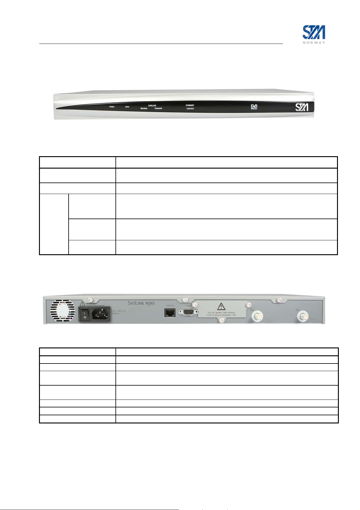
The STM SatLink 1000, 1900, 1901 and 1910 are the indoor units (IDUs) of the STM SatLink VSAT
family of DVB-RCS VSATs. They perform several functions: they are satellite modems (at Layer 1);
they handle data link layer processing (at Layer 2) for both satellite and LAN communications; and they
act as IP routers and DHCP servers (at Layer 3). All SatLink IDUs provide an Ethernet 10/100 LAN
interface for one or more PCs to engage in two-way communication via a SatLink (or any DVB-RCS
compliant) satellite network.
Figure 1: SatLabs Approved STM SatLink 1000 and 1910 Indoor Units (IDUs)
Figure 2: STM SatLink Outdoor Unit (ODU)
Copyright © 2006-2007 – STM Norway AS
Publication no. 101557, Rev. U, August 9th, 2007
Page 5
Page 6

1.1 About this User Guide
This User Guide covers the installation and operation of the STM SatLink 1000/1900/1901/1901,
commonly also referred to as the indoor unit (IDU) of the DVB-RCS VSAT, together with the
accompanying outdoor unit (ODU) equipment. It is intended for DVB professionals, such as service
providers and installers. Therefore, it does not contain information for non-professional users, such as
given in the user manuals of consumer electronics products.
The information given pertains to the following STM software (SW) and hardware (HW) versions and
releases:
SatLink IDU Software
• STM SatLink Boot loader, P/N 101225, SW build 1.8.0.2 and later
• STM SatLink Boot loader, P/N 106267, version 9.0.0 and later
• STM SatLink DVB-RCS VSAT Software, P/N 101224, version 12.0.0 and later
SatLink VSAT IDU Hardware models
• STM SatLink 100 DVB-S2 Plug-in card for SatLink 1910, P/N 107261
• STM SatLink 1000, P/N 103346
• STM SatLink 1900, P/N 100715
• STM SatLink 1901, P/N 102105
• STM SatLink 1910, P/N 103798
Ku-band Equipment
Transceivers
• STM SatLink 4033, P/N 104804
• STM SatLink 4035, P/N 106546
1.2 Initial Configuration
The STM SatLink VSAT IDU must be configured before it can communicate via the satellite to and from
the network Hub. The parameters to be configured are explained in section 6.2.
The configuration of the VSAT IDU can be carried out using the configuration tools:
• Command Line Interface (CLI)
- Via RS232/Terminal emulator (e.g. HyperTerminal)
- Telnet
• Web-interface (basic configuration only)
• SNMP
Configuration via CLI is presented in section 5-15, configuration via Web-interface is presented in
Appendix A, and management via SNMP is presented in Appendix E. The Web interface can be used for
most common configuration tasks, while advanced configuration is only available via SNMP and CLI.
1.3 Symbols
NOTE
Additional information that the reader should pay special attention to.
WARNING
System malfunction may occur if the warning-information is violated.
Copyright © 2006-2007 – STM Norway AS
Publication no. 101557, Rev. U, August 9th, 2007
Page 6
Page 7

2. Unpacking
Check that the following items are in the box received, then unpack.
• SatLink 1000, 1900, 1901, or 1910
• Stand for vertical placement (SatLink 1000 only)
• AC adapter (SatLink 1000 only)
• Mains cord
• Brackets for 19” rack mounting (SatLink 1900/1901/1910 only)
Copyright © 2006-2007 – STM Norway AS
Publication no. 101557, Rev. U, August 9th, 2007
Page 7
Page 8

3. Installation
3.1 Before installation
3.1.1 Safety
Follow these guidelines to ensure general safety:
• Always comply with national and local electrical codes.
• Keep the installation area clear and dust free during and after installation.
• Keep tools and all components away from walk areas.
• Do not wear loose clothing, jewellery (including rings and chains), or other items that might get
caught on the IDU, the ODU or the interconnecting cables.
• Do not work on the system or connect or disconnect cables during lightning storms.
Follow these guidelines when working with electrical equipment:
• Disconnect all power and external cables before installing or removing a SatLink VSAT IDU.
• Do not work alone when potentially hazardous conditions exist.
• Never assume that power has been disconnected from a circuit; always check.
• Do not act in any way that creates a potential hazard to people or makes the equipment unsafe.
• Never install equipment that appears damaged.
• Carefully examine your work area for possible hazards such as moist floors, unearthed mains
extension cables and missing protective earths.
Should an electrical accident occur:
• Be cautious – do not become a victim yourself.
• Turn off electrical power to the system.
• If possible, send another person to get medical aid. Otherwise, assess the condition of the victim and
then call for help.
• Determine if the victim needs artificial respiration or external cardiac compressions; then take
appropriate action.
3.1.2 Site requirements
The STM SatLink VSAT IDU shall be connected to the mains 110/230 VAC, 50-60Hz.
Copyright © 2006-2007 – STM Norway AS
Publication no. 101557, Rev. U, August 9th, 2007
Page 8
Page 9

3.2 SatLink VSAT IDU front and back panels
3.2.1 SatLink 1000 front and back panel
Figure 3: SatLink 1000 Front panel
LED Colour, indicates
Power
Error
Satellite Receive
Transmit
Ethernet Link/Act
Blue, lights steadily when power switch is on and unit is powered. Flashes when loading
software.
Red, lights steadily when an error event occurs and during reboot.
Blue, flashes when the receiver is searching for the carrier.
Lights steadily when receiver is on and functioning properly.
Flashes when IP packets are received from the Satellite Interface (the Hub).
Blue, flashes rapidly when a continuous wave (CW) is transmitted.
Lights steadily when the VSAT is logged on to the DVB-RCS Hub.
Flashes when IP packets are transmitted to the Satellite Interface (the Hub).
Blue, lights steadily when Ethernet connectivity is OK.
Flashes slowly when Ethernet packets are transferred via the Ethernet interface.
Table 1: SatLink 1000 front-panel LEDs
Figure 4: SatLink 1000 back panel
Item Description
On/off switch Mains power on (1) or off (0).
Mains Connector Connector for cable to the 24 V DC power transformer (external power supply provided
with STM SatLink 1000 VSAT)
Ethernet
Connector
COM1 Connector Nine-pin connector for connecting CLI interface to a computer serial RS232 interface.
Rx coaxial jack
Tx coaxial jack
RJ45 connector for IP traffic to connect to a PC, Ethernet switch, IP router etc. 10BASE-T
or 100BASE-T modes are detected automatically.
Coaxial 75 Ω F-type jack for the cable to the LNB.
Coaxial 75 Ω F-type jack for the cable to the BUC.
Table 2: SatLink 1000 back panel description
Copyright © 2006-2007 – STM Norway AS
Publication no. 101557, Rev. U, August 9th, 2007
Page 9
Page 10
3.2.2 SatLink 1910 front and back panel
Figure 5: SatLink 1910 Front panel
LED Colour, indicates
Power
Error Red, lights steadily when an error event occurs and during reboot.
Satellite Receive Blue, flashes when the receiver is searching for the carrier.
Transmit
Ethernet Link/Act
Blue, lights steadily when power switch is on and unit is powered. Flashes when loading
software.
Lights steadily when receiver is on and functioning properly.
Flashes when IP packets are received from the Satellite Interface (the Hub).
Blue, flashes rapidly when a continuous wave (CW) is transmitted.
Lights steadily when the VSAT is logged on to the DVB-RCS Hub.
Flashes when IP packets are transmitted to the Satellite Interface (the Hub).
Blue, lights steadily when Ethernet connectivity is OK.
Flashes slowly when Ethernet packets are transferred via the Ethernet interface.
Table 3: SatLink 1910 front-panel LEDs
Figure 6: SatLink 1910 back panel
Item Description
On/off switch Mains power on (1) or off (0).
Mains Connector Standard recessed plug for Mains cord.
Ethernet
Connector
COM1
Connector
Cover for Accessory Card Not used.
Rx coaxial jack
Tx coaxial jack
RJ45 connector for IP traffic to connect to a PC, Ethernet switch, IP router etc. 10BASET or 100BASE-T modes are detected automatically.
Nine-pin connector for connecting CLI interface to a computer serial RS232 interface.
Coaxial 75 Ω F-type jack for the cable to the LNB.
Coaxial 75 Ω F-type jack for the cable to the BUC.
Table 4: Description of SatLink 1910 back panel
Copyright © 2006-2007 – STM Norway AS
Publication no. 101557, Rev. U, August 9th, 2007
Page 10
Page 11

3.2.3 SatLink 1900 and 1901 front and back panels
Figure 7: SatLink 1900 and 1901 front panel.
LED Colour, indicates
Power
Error
Satellite Receive
Transmit
Ethernet Receive
Transmit
Blue, lights steadily when power switch is on and unit is powered. Flashes when the software
is loading.
Red, lights steadily when an error event occurs; lights steadily during reboot.
Blue, flashes when the receiver is searching for the carrier.
Lights steadily when receiver is on and functioning properly.
Flashes when IP packets are received from the Satellite Interface (the Hub).
Blue, flashes rapidly when a continuous wave (CW) is transmitted
Lights steadily when the VSAT is logged on to the DVB-RCS Hub.
Flashes when IP packets are transmitted to the Satellite Interface (the Hub).
Blue, lit when Ethernet packets from the local network are being received.
Blue, lit when Ethernet packets are sent to the local network.
Table 5: SatLink 1900 and 1901 front-panel LEDs
Figure 8: SatLink 1900/1901 Back panel
Item Description
On/off switch Mains power on (1) or off (0).
Mains Connector Standard recessed plug for Mains cord.
COM1
Connector
Ethernet
Connector
Node/Hub
Push-button toggle
External I/O Not used
Rx coaxial jack
Tx coaxial jack
Nine-pin connector for connecting CLI interface to a computer serial RS232 interface.
RJ45 connector for IP traffic to connect to a PC, Ethernet switch, IP router etc. 10BASE-T
or 100BASE-T modes are detected automatically.
Selects HUB or NODE configuration of the Ethernet port. NODE normally is used when
connecting to an Ethernet switch or Ethernet hub, while HUB is used when connecting
directly to a single PC.
Coaxial 75 Ω F-type jack for the cable to the LNB.
Coaxial 75 Ω F-type jack for the cable to the BUC.
Table 6: SatLink 1900 and 1901 back panel connectors and switches
Copyright © 2006-2007 – STM Norway AS
Publication no. 101557, Rev. U, August 9th, 2007
Page 11
Page 12

3.3 IDU Installation
3.3.1 On desktop or shelf
Place the STM SatLink VSAT IDU on a flat, stable surface, such as a desktop or shelf, close to the PC or
network device to which it will be connected. Keep its top, bottom and all sides unobstructed to ensure
free airflow. Rubber feet on the bottom provide adequate clearance. Ensure that there is at least 10 cm
clearance at the back to allow room for cable connections.
3.3.2 In rack
The rack or cabinet should be properly secured to prevent tipping. Equipment that is
installed in a rack or cabinet should be mounted as low as possible, with the heaviest units
lower down, and lighter units toward the top.
Precautions:
• Ensure that the mains circuits are properly earthed and use the mains cord supplied with the
SatLink VSAT IDU to connect it to the mains outlet.
• If your installation requires a different mains cord than the one supplied, ensure that the cord used is
certified as indicated by the stamped or embossed logo of the electrical safety authority in your
country.
• If the on/off switch on the back panel is difficult to reach when the unit is fitted in the rack, ensure
that the mains outlet into which it is plugged can be reached so it may be unplugged if need be.
• Ensure that the unit does not overload the mains circuit, wiring or over-current protection. To
determine the possibility of overloading the supply circuits, add together the ampere ratings of all
devices installed on the same circuit as the STM SatLink VSAT IDU and compare the total with the
rating limit for the circuit. The maximum ampere ratings are usually printed on units near their mains
connectors.
• Do not install the STM SatLink VSAT IDU in a location where the operating ambient temperature
may exceed 45°C.
• Ensure that the airflow around the sides and back of the SatLink VSAT IDU is not restricted.
The STM SatLink 1900/1901/1910 can be mounted in any EIA-standard 19-inch telecommunications
rack or cabinet. The STM SatLink 1000 needs to be placed on a shelf if it is to be placed in a rack.
Use a Torx screwdriver and attach the mounting brackets to the router with the screws supplied. Hold the
unit securely, brackets attached, and move it vertically until rack holes line up with the bracket notches,
then insert and tighten the four screws holding the brackets to the rack.
Copyright © 2006-2007 – STM Norway AS
Publication no. 101557, Rev. U, August 9th, 2007
Page 12
Page 13
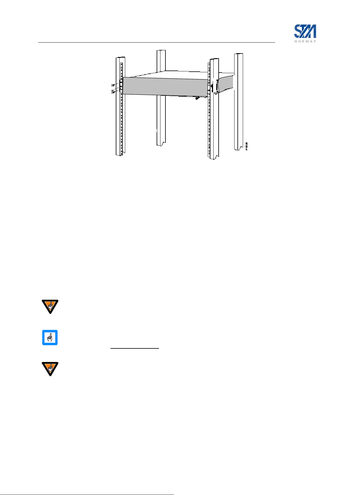
Figure 9: Rack Mounting
3.4 ODU installation
Install the ODU as described in Appendix F, reference [1], and the antenna installation manual. When
installing the STM SatLink 403x transceiver, please check Table 13 in Appendix G whether an adapter is
required to interface the antenna feed horn.
3.5 Interface connections
3.5.1 Rx/Tx cables between IDU and ODU
The coaxial cables from the ODU are connected to the type F coaxial jacks on the back panel of the STM
SatLink VSAT IDU.
• Connect one coaxial cable from the ODU Tx module input to the jack marked Tx.
• Connect one coaxial cable from the LNB to the port marked Rx on the back panel.
Do not connect the Tx cable before the initial configuration of the STM SatLink VSAT
IDU is performed to ensure that incorrect or hazardous signals are not sent to the satellite
Use only 75 Ω coaxial cables fitted with type F plugs for the Rx and Tx cables. Make sure
that the connectors are of a waterproof version such as F-connector RG6 Compression type
from Cablecon (www.cablecon.dk
Do not connect and disconnect the coaxial cables with power connected to the STM
SatLink VSAT IDU.
Hint
Use different colour marking on the Tx and Rx coaxial cables to eliminate likelihood of
interchanging the Rx and Tx coaxial cables.
), article no 99909446, STM article no 106208
Copyright © 2006-2007 – STM Norway AS
Publication no. 101557, Rev. U, August 9th, 2007
Page 13
Page 14

3.5.2 Ethernet connection to a Local Area Network (LAN)
The STM SatLink VSAT IDU may be connected to a single PC or to a network via the RJ-45 Ethernet
jack on the back panel.
• Plug one end of the Ethernet cable into the RJ-45 jack on the back panel.
• Plug the other end of the Ethernet cable into the RJ-45 jack a Local Area Network (LAN) device such
as an Ethernet hub, switch or router, according to its manufacturer’s instructions.
For the STM SatLink 1900 and 1901, toggle the back panel push button to set Ethernet HUB or NODE
mode. Toggle to NODE when connecting to an Ethernet switch or an Ethernet hub and toggle to HUB
when connecting to a single PC.
For the STM SatLink 1000 and 1910 there is no push button on the back panel as Ethernet HUB or
NODE mode will be auto-detected and the correct mode chosen automatically.
3.5.3 Mains connection
The STM SatLink 1900/1901/1910 models have internal power supply and consequently are connected
directly to a 110/230 VAC 50/60Hz outlet using a standard 230 VAC mains cord.
3.5.4 Power supply
The STM SatLink 1000 has an external power supply that is connected to a 110/230 VAC 50/60Hz outlet
using a standard mains cord.
The STM SatLink 1000 must only be connected to the external power supply that is
approved by STM , PN 104170 (LEI-S2425D / Model No. STD-2425). Use of another power
supply will void warranty.
Copyright © 2006-2007 – STM Norway AS
Publication no. 101557, Rev. U, August 9th, 2007
Page 14
Page 15

4. Connecting a PC to the SatLink VSAT
After installation as described in Chapter 3 is carried out, the VSAT IDU is ready to be powered on.
4.1 Windows TCP/IP configuration
Verify that the TCP/IP configuration is correct for PCs connected to the LAN you plan to use for your
SatLink VSAT. Push the start-button in Windows, select the Control panel and then open Network
Connections. Right-click on the relevant Local Area Connection and select Properties. A new window
showing the Network Connection Properties will pop up. In the General submenu of this window, scroll
down, select Internet Protocol (TCP/IP) and then push the Properties button shown in Figure 10. Then
configure the PC client to obtain the IP address automatically from the VSAT IDU (section 4.1.1) or
configure the PC with a static IP address (section 4.1.2).
Figure 10: Windows XP menu for configuring the client TCP/IP configuration.
Copyright © 2006-2007 – STM Norway AS
Publication no. 101557, Rev. U, August 9th, 2007
Page 15
Page 16

4.1.1 Dynamic IP configuration of PCs connected to the VSAT LAN
By default the DHCP server in the SatLink VSAT is enabled. When the SatLink VSAT is powered on, all
PCs connected to the VSAT LAN can automatically retrieve their IP configuration from the DHCP
server. The user should verify that the Window clients are configured to obtain an IP address and DNS
server address automatically. Figure 11 shows the correct Windows XP configuration when the DHCP
server is enabled in the VSAT.
Figure 11: Windows XP TCP/IP setting when DHCP server is enabled in the VSAT
From an MS-DOS window, the user may type ipconfig /all command to verify that the computer has
received correct configuration parameters from the DHCP server such as IP address, subnet mask, default
Gateway, DNS servers and lease time.
Figure 12: ipconfig /all print out from an MS-DOS window
Copyright © 2006-2007 – STM Norway AS
Publication no. 101557, Rev. U, August 9th, 2007
Page 16
Page 17

4.1.2 Static IP configuration of PCs connected to the VSAT LAN
When the DHCP server in the SatLink VSAT is disabled, all PCs attached to the VSAT LAN must be
configured with static IP addresses that are within the address range of the VSAT subnet (see section
6.2.1). The IP configuration parameters to use for PCs connected to the VSAT LAN are supplied from the
system operator or service provider. Please configure the IP address, Subnet mask, Default gateway,
Preferred DNS server, and optionally the Alternate DNS server as shown in Figure 13.
Ensure that the actual IP addresses supplied by the system operator / service provider are
configured and not the IP addresses in the example figure.
Figure 13: Windows XP TCP/IP setting when DHCP server is disabled in the VSAT
Example:
A host may have the following configuration; IP address 192.168.0.2, Subnet mask 255.255.255.0 and
default gateway 192.168.0.1, where the IP address of the default gateway should be the IP address of the
VSAT LAN interface.
Copyright © 2006-2007 – STM Norway AS
Publication no. 101557, Rev. U, August 9th, 2007
Page 17
Page 18

5. Using the Command Line Interface of the SatLink VSAT
The command line interface can be accessed via either Telnet or the RS-232 port for management of the
SatLink VSAT IDU as well as for showing status and reports.
5.1 CLI users access rights
Four levels of CLI user access rights are available for differentiating user privileges:
• Level 2: installer
• Level 3-5: end users
When shipped from the factory, one user is pre-configured in the SatLink VSAT:
User name Factory default password Privilege level
Install dvbrcs 2
When accessing the CLI via RS-232, if the login prompt is not displayed type ENTER. The login prompt
Login: should then be displayed. Then login with the install user:
Login: install
Password: dvbrcs
When the command prompt is displayed you will now have access to the CLI with privilege level 2.
New users may be added with the CLI command
command
changed with the CLI command
user del, and the password of the current user or users with lower privilege levels can be
user passwd. To list all defined users with lower privilege level than
the user currently logged in, use the CLI command
user commands.
For security reasons we recommend that you change the factory set password to your own personal one.
user add, existing users deleted with the CLI
user show. Type ? user to get further help on the
5.2 Online help
In the CLI a list of available commands can be displayed by typing ? <ENTER> (question mark and the
ENTER key). The CLI command groups will then be shown:
Example:
# ?
? : ? <submenu|command>
device : Device configuration
dvb : DVB interface configuration
eth : Ethernet configuration
ip : IP configuration
log : Event log
misc : Miscellaneous commands
odu : ODU configuration
sw : Software upgrade & licenses
user : User configuration
Copyright © 2006-2007 – STM Norway AS
Publication no. 101557, Rev. U, August 9th, 2007
Page 18
Page 19

To display the available commands within one sub-menu type ? <sub-menu>.
Example:
? ip
show : ip show [-mcast]
set : ip set <ifnum> <ipaddr> <mask>
addroute : ip addroute <destaddr> <netmask> <next hop> <ifnum>
delroute : ip delroute <destaddr> <netmask> <next hop>
intf : Interface configuration
dhcp : DHCP configuration
dns : DNS configuration
qos : IP QOS configuration
To get further help on a specific CLI command type
Example:
# ? ip set
USAGE:
ip set <ifnum> <ipaddr> <mask>
ifnum Interface number (1=LAN, 3=Satellite)
ipaddr IP address for the interface
mask Netmask for the interface
Set the IP address and subnet mask for the specified interface
Example:
ip set 1 10.10.1.1 255.255.255.248 will set the LAN IP address to
10.10.1.1 and the LAN netmask to
255.255.255.248
See also:
ip show, ip addroute, ip delroute
#
? <cmd>.
5.3 Logging of events
The SatLink VSAT logs certain events to a log stored in RAM. See Appendix J.5 for a list of the different
events and needed actions. Use the CLI command
The events are divided in four different severity levels:
0. Minor
1. Normal
2. Major
3. Critical
Events with severity level Major will normally cause disruption in the data transfer, while events with
severity level Critical normally will require user intervention in order to restore the data communication
with the DVB-RCS Hub.
To have access to the log of events also after the VSAT software has been rebooted, the event above a
specified severity level can be logged to file. Use the CLI command
events to file, set the minimum severity level of events that shall be logged to file and set the maximum
size for the logfile. By default, Major and Critical events are logged to file.
Copyright © 2006-2007 – STM Norway AS
Publication no. 101557, Rev. U, August 9th, 2007
log show to show the log from memory.
log file to enable logging of
Page 19
Page 20

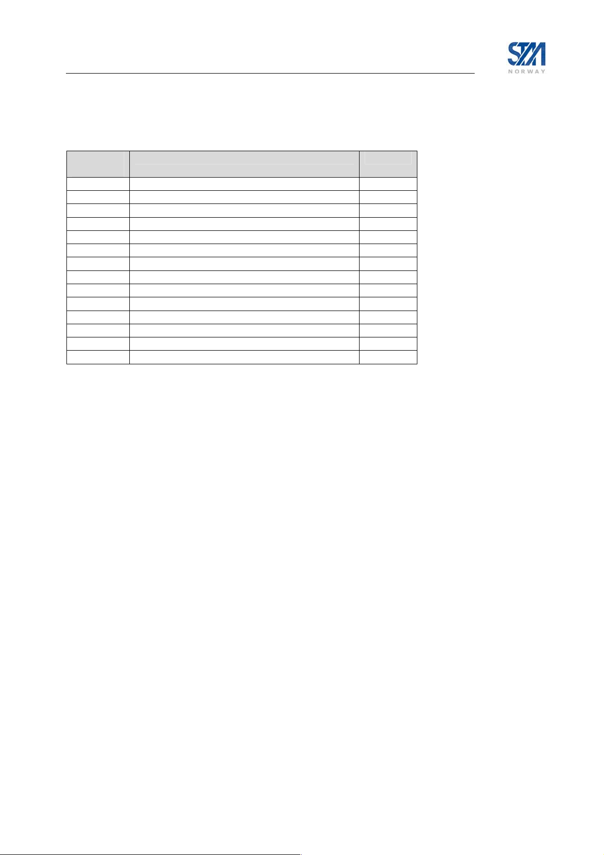
5.4 CLI command summary
The available CLI commands are listed below.
CLI commands Available in
Boot
SW
? [sub-menu] [cmd] x x 5
del <filename> x x 2
ren <filename1> <filename2> x x 2
mv <filename1> <filename2> x x 2
dir [ext] x x 5
type <filename> x x 5
dload <filename> <ipaddr> [<localname>] x x 2
upload <filename> <ipaddr> [<remotename>] x x 2
ping <ipaddr> x x 5
exit x x 5
logout x x 5
restart x x 5
save config x 5
device snmp show
device snmp community <name> <ro|rw>
[<ipaddr> <mask>]
device snmp delcommunity <name>
device manager show
device manager add <func> <if> [<ip> <mask>]
device manager del <func> <if> [<ip> <mask>]
device name <name>
device contact <contact>
device location <location>
device show [-dvbs2]
dvb tx autostart <on|off|traffic> [<timeout>] x 2
dvb tx calibrate [<freq> [<timeout>]] x 2
dvb tx cw <on|off> [-notrack] [<pow> [<freq>
[<timeout>]]]
dvb tx cwfreq <freq> x 2
dvb tx eirp <eirp> x 2
dvb tx logoff x 2
dvb tx logon x 2
dvb tx outpow <pow> x 2
dvb tx show [-burst|-capacity|-queue|-ts] x 5
dvb rx autostart <on|off> x 2
dvb rx start x 2
dvb rx stop x 2
dvb rx fwdlink <idx> <pri> [<symbrate>
[<freq> [<mode> [<popid>]]]]
dvb rx phy [-internal | -satlink100] x 2
dvb rx show [-pid] x 5
dvb rx tablecache <on|off>
[<tunerRetryTime>]
dvb cr show [-timeout|-interval|-capacity] x 2
dvb pos lat <deg> <min> <mindec> <dir> x 2
dvb pos long <deg> <min> <mindec> <dir> x 2
1
x 1
x 1
x 1
x 1
x 1
x 1
x 2
x 2
x 2
x 5
x 2
x 2
x 2
Available in
Application
SW
User
Privilege
Level
1
CLI commands are available only when the license for the MOBILE software option is installed
Copyright © 2006-2007 – STM Norway AS
Publication no. 101557, Rev. U, August 9th, 2007
Page 20
Page 21

CLI commands Available in
Boot
SW
Available in
Application
SW
User
Privilege
Level
dvb pos alt <height> x 2
dvb pos delayburst <nera|satlabs|ticks> x 2
dvb pos show x 5
eth mode <mode> x 5
eth vlan [-del|-allow|-block] <id> [<if>]
eth primap [-del] <pri> <qos>
2
2
x 2
x 2
eth show x 5
ip addroute <destaddr> <netmask> <next hop>
x x 2
<ifnum>
ip delroute <destaddr> [<netmask> [<next hop>
x x 2
[<if>]]]
ip qos mask <index> <group> {{+|-}<tag>
x 2
<tag-parms>}+
ip qos show x 5
ip set <ifnum> <ipaddr> <mask> x x 2
ip show [-mcast] x x 5
ip dns server <primary> [secondary] x 3
ip intf add <if> x 2
ip intf del <if> x 2
ip intf addroute <ifin> <ifout> x 2
ip intf delroute <ifin> x 2
ip nat <enable|disable >2
ip nat global <add|del> <gladdr>
ip nat static add <gladdr> <locaddr>
ip nat static del <gladdr>
ip nat napt add <gladdr> <globport> <locaddr>
<locport>
ip nat napt del <gladdr> <globport>
ip nat <show>
2
2
2
2
2
2
x 2
x 2
x 2
x 2
x 2
x 2
x 5
ip dhcp <enable|disable> X 3
ip dhcp show X 5
ip dhcp leasetime <time> [unit] X 3
ip dhcp dns <primary> <secondary> X 3
ip dhcp exclude <no> X 3
ip gre add <destaddr> <netmask>
<tunnelipaddr>
ip gre del <ifnum>
ip gre show
ip pep disable
ip pep enable <mode>
ip pep server <ipaddr>
ip pep show
2
2
2
2
2
2
2
log file <enable|disable>
X 2
X 2
X 5
X 2
X 2
X 2
X 5
X 5
[<severity> [<filesize>]]
log show X 5
odu lnb <type> X 2
odu txtype <type> X 2
odu antenna <type> X 2
odu show X 5
sw license <feature> <key>
2
CLI commands are available only when the license for this software option is installed.
X 2
Copyright © 2006-2007 – STM Norway AS
Publication no. 101557, Rev. U, August 9th, 2007
Page 21
Page 22

CLI commands Available in
Boot
SW
Available in
Application
SW
User
Privilege
Level
sw mcast <value> [<pid>] [<addr>] [<port>]
sw upgrade [-default] [<filename>
[<tftp-ip-addr>]]
sw restore X 2
sw show X 5
user add <loginname> <passwd>
[privilege level]
user del <loginname> x X 4
user passwd {loginname | oldpasswd}
<newpasswd>
user show x X 5
X 2
x X 4
x X 5
X 2
Copyright © 2006-2007 – STM Norway AS
Publication no. 101557, Rev. U, August 9th, 2007
Page 22
Page 23

6. SatLink VSAT configuration and line-up
Before powering on the SatLink VSAT for the first time, ensure that the Tx coaxial cable from the VSAT
to the ODU is disconnected to avoid that incorrect and potentially damaging signals are sent to the
satellite. Follow all the procedures below when installing the SatLink VSAT and lining up the ODU.
6.1 Power on and logon
1) To view the boot processes of the SatLink VSAT, please connect a PC to the serial interface and
launch a Terminal Emulator as described in Appendix B. Otherwise go to step 2.
2) Turn on the power of the SatLink VSAT.
3) When turning on the SatLink VSAT first the Boot SW is loaded. A message such as the one below is
displayed on the CLI/RS-232 when the boot SW starts. Telnet is not available until the application
has been started.
STM SatLink Boot-loader
- SW ID 106267, Revision 9.0.0.1
File system initialised
Press return to enter boot-loader
Under normal circumstances the user should not need to enter the boot-loader and should ignore the
“press return to enter boot-loader” message. The DVB RCS application will load automatically once
the boot SW load has completed. See Appendix I for further details concerning the boot SW. If
access to the boot-loader is required, press return within 10 seconds to display the login-prompt for
entering the boot-load. After the timer has expired, the DVB-RCS application will be loaded. The
message
4) Wait for the application software to be loaded and activated (typically takes 1-1.5 minutes).
The power LED on the front of the SatLink VSAT will blink when the SW is booting and will stay on
when the SW has successfully started. If watching the boot process on the RS-232 output, a printout
similar to this will be displayed when the SW has booted.
SatLink 1000
- Main board ID 102805, Revision R6.0
- SW ID 101224, Revision 12.0.2 Build 39
File system initialised
Ethernet Interface MAC Address : 00:60:c0:2f:a7:32
DVB Interface MAC Address : 00:60:c0:2f:a7:32
Retrieving configuration....done
Loading application will be shown when the application starts to load.
When the SatLink VSAT is configured for use with the SatLink 4033/4035 transceiver and the
TX cable is not connected to the ODU then the following error message will be shown when
the SW has booted:
ODU Initialisation failed. Unable to establish DiSEqC communication.
Please check connection to ODU and that the ODU supports
DiSEqC communication
This is normal and just indicates that the VSAT can not communicate with the transceiver
since the cable is not yet connected.
Copyright © 2006-2007 – STM Norway AS
Publication no. 101557, Rev. U, August 9th, 2007
Page 23
Page 24

5) At this point the Telnet server in the SatLink VSAT is started and a Telnet session can be opened for
managing the VSAT. Local Echo must be enabled in the Telnet Client if the input from the keyboard
shall be displayed. Recommended Telnet clients are Tera Term (see Appendix D), PuTTY
3
, and the
built in Telnet client in Windows. Note that Local Echo by default is set to “off” in Windows XP.
Alternatively HyperTerminal or another terminal emulator connected via the serial interface can be
used (see Appendix B). From this point the SatLink VSAT can also be managed via the Web
interface and SNMP.
Use the SatLink VSAT’s Satellite Interface (DVB) IP address when using Telnet over the satellite
link (from the Hub), and the VSAT’s LAN (Ethernet) IP address when using Telnet from the local
LAN.
When shipped from the factory the SatLink 1000 and 1910 VSAT LAN (Ethernet) IP-addresses are
set to 192.168.0.1 and the subnet mask to 255.255.255.0. If the SatLink VSAT LAN (Ethernet) IPaddress has been changed from the factory default to an unknown address, one must use CLI via RS232 to do the initial configuration.
The SatLink VSAT can handle at most three simultaneous Telnet connections including aborted
connections. The Telnet session will be automatically terminated after 20 minutes without activity. If
a Telnet session is refused this can be due to all three connections being aborted. Please wait until the
timeout has expired and try again.
6) Login as the administrator user install with the factory default password dvbrcs :
Login: install
Password: dvbrcs
SatLink 1000
- Main board ID 102805, Revision R6.0
- SW ID 101224, Revision 12.0.2 Build 39
4
One must press Enter once to get the login-prompt to display if using the CLI via RS-232.
If the input from the keyboard is not displayed when typing the username and password,
check that the Local Echo is enabled in the Telnet client.
7) The SatLink VSAT should now be ready to be configured as described in the following sub-sections.
6.2 Initial configuration of parameters
The VSAT must be configured with a number of parameters before the VSAT can acquire the forward
link and communicate with the network Hub. A default configuration specifying most of these parameters
is usually pre-loaded on each STM SatLink VSAT, either in the factory or by the service provider before
installation. The parameters that usually need to be configured by the installer are:
- Antenna to be used
- Forward link frequency and symbol rate
- VSAT population ID.
- VSAT geographical position
3
http://www.chiark.greenend.org.uk/~sgtatham/putty/download.html
4
dvbrcs is the factory default setting for the password. The password might have been changed after
shipment from the factory.
Copyright © 2006-2007 – STM Norway AS
Publication no. 101557, Rev. U, August 9th, 2007
Page 24
Page 25

Many DVB-RCS networks support automatic configuration of the VSAT’s IP parameters
when the VSAT logs on to the network. In that case, the IP address configuration described
in section 6.2.1 below can be skipped. Please check with your service provider if local
configuration of the VSAT’s IP addresses is necessary.
6.2.1 IP configuration
The DVB-RCS system operator manages all IP addresses in the DVB-RCS system including the DVB
interface IP address and the LAN IP addresses of all DVB-RCS VSATs. The IP-addresses can be set
automatically in the VSAT by the DVB-RCS system operator, or manually by the installer. Please check
with your operator which method applies.
The procedure below is required for manual IP-address configuration only. If the DVB-RCS network
supports automatic configuration of the VSAT’s IP parameters, skip this part and go to section 6.2.2.
Please make sure that the IP addresses and netmasks are entered exactly as specified by the DVB-RCS
system operator, as any deviation may result in loss of communication with the IP network.
1) Set the LAN IP address of the unit
– Enter the CLI command
where
<aaa.bbb.ccc.ddd> is the IP address and <eee.fff.ggg.hhh> the netmask.
Example:
# ip set 1 10.10.20.1 255.255.255.248
2) Set the DVB IP address (Satellite interface) of the unit:
– Enter the CLI command
where
<aaa.bbb.ccc.ddd> is the IP address and <eee.fff.ggg.hhh> the netmask.
Example:
# ip set 3 10.10.21.1 255.255.255.0
3) Verify that the IP addresses and netmasks are set correctly:
– Enter the CLI command
ip set 1 <aaa.bbb.ccc.ddd> <eee.fff.ggg.hhh>
ip set 3 <aaa.bbb.ccc.ddd> <eee.fff.ggg.hhh>
ip show
Copyright © 2006-2007 – STM Norway AS
Publication no. 101557, Rev. U, August 9th, 2007
Page 25
Page 26

Example:
If the values above have been configured the
ip show command shall give the following result.
(Interface 1 is the LAN interface, interface 2 is not used, and interface 3 is the DVB (satellite)
interface):
# ip show
Interfaces
If IPAddress SubnetMask BroadCastAddr MTU Alias AdminStatus
1 10.10.20.1 255.255.255.248 10.10.20.7 1500 eth0 1
2 N/A N/A N/A 4074 air0 1
3 10.10.21.1 255.255.255.0 192.168.255.255 4074 dvb0 1
Interface Statistics
------------- Input ----------------- ------------- Output ----------------
If UCast NUCast Disc Octets UCast NUCast Disc Octets
1 14496815 48920 1068 967104678 29153597 1278 1 970900724
2 0 0 0 0 0 0 0 0
3 14754693 70483 2506 486270184 21082393 0 4 1308841911
IP Receive Deliver Errors Discards Forward Request NoRoute Discards
73163754 667213 4 4 43077496 304307 0 280
Routing Table
DestMask RouteMask NextHop If
0.0.0.0 0.0.0.0 10.10.21.254 3
10.10.20.0 255.255.255.248 0.0.0.0 1
10.10.21.0 255.255.255.0 0.0.0.0 3
4) Save the IP configuration to Flash
– Enter the CLI command:
save config
– Example:
# save config
Saving Configuration. This will take ~20 secs
# Configuration Saved
#
If the prompt sign (#) does not show, push enter.
Copyright © 2006-2007 – STM Norway AS
Publication no. 101557, Rev. U, August 9th, 2007
Page 26
Page 27

6.2.2 Antenna and ODU parameter configuration
The STM SatLink VSAT is normally pre-configured to be used together with the STM SatLink 403x
Transceiver. The CLI command
ODU transmitter type and ODU receiver type, both set to STM SatLink 403x.
It is possible to configure the STM SatLink VSAT to operate together with other transmitters and
receivers than SatLink 403x. The valid ODU transmitters (BUC) are listed in Table 7 and the valid ODU
receivers (LNB) are listed in Table 9 (the list is also available using the CLI help command
? odu txtype). Choosing the ODU transmitter to be STM SatLink 403x will automatically lock the
ODU receiver type to STM SatLink 403x.
Please make sure that the correct ODU transmitter (BUC) type is selected according to the table below as
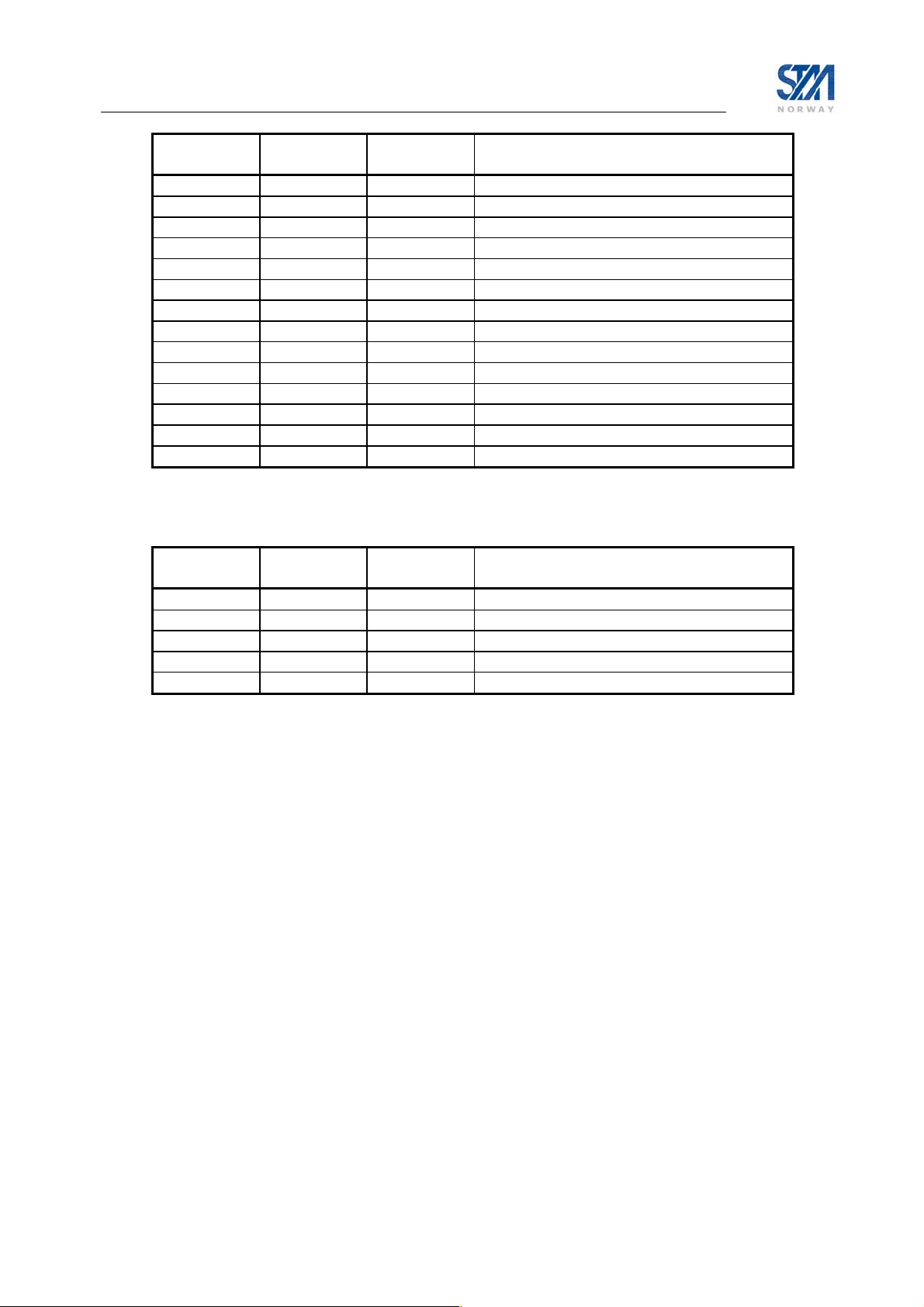
the return link communication will otherwise not work.
ODU
ODU Transmitter (BUC) STM Product Number
Transmitter #
(type)
Ku-band
30 Invacom TUL-204 104041 All
42 JRC NJT5096 All
43 JRC NJT5097 All
45 JRC NJT5017 All
65 ND SatCom RFT 35W All
C-band
80 JRC NJT5652 105268 All
81 JRC NJT5656 105269 All
92 Zinwell ZTX-C3300F 105701 All
90 Zinwell ZTX-C3301F 105276 All
93 Zinwell ZTX-C3700F 105700 All
91 Zinwell ZTX-C3701F 105274 All
odu show will show the ODU configuration with the two parameters,
HW Revision
(P/N)
106546 (SatLink 4035) All 11 STM SatLink 403x
104804 (SatLink 4033) All
Table 7: Overview of supported ODU transmitters (BUCs)
To configure use of an ODU transmitter (BUC) listed in the table above, please enter the CLI command
odu txtype <type> where type is the number from the first column in the table above.
Example:
# odu txtype 45
selects the JRC NJT5017F transmitter. Use the command odu show to view the ODU configuration
parameters.
Copyright © 2006-2007 – STM Norway AS
Publication no. 101557, Rev. U, August 9th, 2007
Page 27
Page 28
When using the STM SatLink 4033/4035 Transceiver, the STM SatLink VSAT must be configured with
the antenna type in use in order to calculate the transmitted EIRP correctly. The following antennas are
supported:
Antenna #
Antenna (Ku-band) Size
(type)
2 Andrew Type 960 0.96 m
1 Andrew Type 123 1.20 m
5 Andrew Type 184 1.80 m
7 Andrew Type 244 2.40 m
11 Patriot TX-090KU 0.96 m
12 Patriot TX-100KU 1.00 m
13 Patriot TX-120KU 1.20 m
14 Patriot TX-240KU – BATWING 2.40 m
15 Prodelin Series 1132 1.20 m
16 Prodelin Series 1184 1.80 m
17 Prodelin Series 1250 2.40 m
8 Seatel 4003 1.00 m
9 Visiosat KIT 90 EMIT 0.90 m
10 Visiosat KIT 120 EMIT 1.20 m
Table 8: Overview of supported Antenna types
Please see Appendix G (Table 13 on page 98) for more detailed information regarding the antennas that
can be used with the STM SatLink 403x transceiver.
The STM SatLink VSAT is normally pre-configured to use the Patriot 0.96m antenna. If another antenna
listed in the table above is to be used, please enter the CLI command
type is the antenna number from the first column in the table above.
odu antenna <type> where
Example:
# odu antenna 13
selects the Patriot 1.2 m antenna. Use the command odu show to view the ODU configuration
parameters.
Copyright © 2006-2007 – STM Norway AS
Publication no. 101557, Rev. U, August 9th, 2007
Page 28
Page 29

Example:
# odu show
Antenna Configuration
--------------------Type Patriot TX-090KU - 0.9m
Tx Gain at 14.25 GHz 40.9dB
Transmitter (BUC) Configuration
------------------------------Type STM SatLink 4033 (14.0-14.5 GHz)
ODU Serial No. 104804030303051100020000
ODU HW Version 3.3
ODU SW Version 1.3
Local oscillator 13.050000 GHz
24V DC supply On
Receiver (LNB) Configuration
---------------------------Type STM SatLink 403x (10.70-12.75
GHz)
Local oscillator - High band 10.600000 GHz
Local oscillator - Low band 9.750000 GHz
Oscillator switching frequency 11.700000 GHz
LO Switching mode 22kHz
13/18V DC supply 13V
The SatLink VSAT can be configured with one of the following LNBs:
ODU LNB #
ODU LNB STM P/N
(type)
Ku-band
20 Invacom SPV-1SM 100816
30 Zinwell ZK-VJ1 104730
40 JRC NJR2535S
41 JRC NJR2536S
42 JRC NJR2537S
C-band
80 Zinwell ZC-VD1 105267
85 Norsat 8000-series
Table 9: Overview of supported ODU receivers (LNB)
Enter the CLI command
# odu lnb <lnbtype> where type is the number from the first column in the
table above to configure the correct LNB.
When ODU BUC is chosen to be the STM SatLink 403x transceiver, the LNB will
automatically be set to STM SatLink 403x. The STM SatLink IDU will detect the STM
SatLink transceiver model being used (i.e. STM SatLink 4033, or 4035) and display the
detected model in the ODU Transmitter (BUC) Type field in the CLI
Copyright © 2006-2007 – STM Norway AS
Publication no. 101557, Rev. U, August 9th, 2007
odu show output.
Page 29
Page 30

Example:
# odu lnb 20
selects the Invacom SPV-1SM LNB. Use the command odu show to view the ODU configuration :
# odu show
Antenna Configuration
--------------------Type Patriot TX-090KU - 0.9m
Tx Gain at 14.25 GHz 40.9dB
Transmitter (BUC) Configuration
------------------------------Type Invacom TUL-204 (14.0-14.5 GHz)
Local oscillator 13.050000 GHz
24V DC supply On
Receiver (LNB) Configuration
---------------------------Type Invacom SPV-1SM (10.70-12.75 GHz)
Local oscillator - High band 10.600000 GHz
Local oscillator - Low band 9.750000 GHz
Oscillator switching frequency 11.700000 GHz
LO Switching mode 22kHz
13/18V DC supply 13V
Finally save the configuration to flash using the command
save config.
The STM SatLink VSAT must be restarted for the new ODU configuration to take effect.
6.2.3 VSAT geographical position
In order to calculate the delay to the satellite correctly for the logon burst the STM SatLink VSAT must
be configured with its own position.
The STM SatLink VSAT by default uses the timing compensation procedure as specified
by SatLabs . For using the STM SatLink VSAT with a DVB-RCS Hub requiring
proprietary timing compensation refer to Appendix L.
1) Find the position of the location where installing the STM SatLink VSAT using a standard GPS.
The STM SatLink VSAT position is entered in one of the following two formats:
a) degrees, minutes, 1/100 minutes, and direction
b) degrees, minutes, seconds, and direction
To convert between the two formats use the formula 1/100 minutes = (seconds/60) x 100
Entering the direction as a number {0,1} selects format a, while entering the direction as a
letter {‘n’,’s’,’e’,’w’} selects format b.
Copyright © 2006-2007 – STM Norway AS
Publication no. 101557, Rev. U, August 9th, 2007
Page 30
Page 31

2) Configure the latitude:
Format a: Enter the CLI command
dvb pos lat <deg> <min> <mindec> <dir> where
deg = degrees [0, 180>
min = minutes [0, 60>
mindec = 1/100 minutes [0,100>
dir = direction. 0 = North. 1 = South.
Format b: Enter the CLI command
dvb pos lat <deg> <min> <sec> <dir> where
deg = degrees [0, 180>
min = minutes [0, 60>
sec = seconds [0, 60>
dir = direction. ‘n’ = North. ‘s’ = South.
Example:
# dvb pos lat 59 52 15 0
or
# dvb pos lat 59 52 09 n
sets the latitude to 59°52.15'N.
3) Configure the longitude:
Format a: Enter the CLI command
dvb pos long <deg> <min> <mindec> <dir> where
deg = degrees [0, 180>
min = minutes [0, 60>
mindec = 1/100 minutes [0, 100>
dir = direction. 0 = East. 1 = West.
Format b: Enter the CLI command
dvb pos long <deg> <min> <sec> <dir> where
deg = degrees [0, 180>
min = minutes [0, 60>
sec = seconds [0, 60>
dir = direction. ‘e’ = East. ‘w’ = West.
Example:
# dvb pos long 10 29 05 0
or
# dvb pos long 10 29 03 e
sets the longitude to 10°29.05'E.
4) Configure the altitude:
– Enter the CLI command
dvb pos alt <height> where
height = height in meters
Example:
# dvb pos alt 60
sets the altitude to 60 meters.
Copyright © 2006-2007 – STM Norway AS
Publication no. 101557, Rev. U, August 9th, 2007
Page 31
Page 32

5) Verify the VSAT position:
- Enter the CLI command
dvb pos show
Example:
# dvb pos show
Latitude : 59d 52.15'N ( 59d 52' 9''N )
Longitude : 10d 29.05'E ( 10d 29' 3''E )
Altitude : 60 m
Timing Reference : SatLabs
PositionSearchN : 0
Position Search Offset : 0
#
7) Save the VSAT position to Flash
– Enter the CLI command:
save config
6.2.4 Forward link parameters
The forward link parameters are used to identify the forward link (outbound link) that is transmitted from
the Hub to the DVB-RCS VSATs. To set the symbol rate and receive frequency of the forward link, use
the following CLI commands:
dvb rx fwdlink <idx> <pri> [<symbrate> [<freq> [<mode> [<popid>]]]]
idx Table index [0,9]. The SatLink VSAT can store up to 10 forward link entries and the
table index is used to identify a single entry. For configurations with only one forward
link entry it is recommended to set this parameter to 0.
pri Forward link search order [0,9]. Search is started for priority 0 and ends with priority 9
For configurations with only on forward link entry it is recommended to set this
parameter to 0
symbrate Forward link symbolrate [sps]
freq Forward link frequency [kHz]
mode Valid modes: [dvbs,dvbs2]
popid Population ID to use for forward link acquisition. The STM SatLink VSAT will select
which group in the DVB-RCS system it belongs to based on the configured population
ID. The population ID to be used is assigned by the Hub Operator.
Verify the settings by typing the CLI command
configuration.
Example:
# dvb rx fwdlink 0 0 24500000 11250000 dvbs2 2
# save config
# dvb rx show
Satellite (DVB) RX Configuration
-------------------------------Auto start : Enabled
Idx Pri Freq[GHz] SymbRate[Msps] Mode PopId
* 0 0 11.250000 24.500000 DVB-S2 2
DVB Receiver Status
-------------------------------Rx State : Off
dvb rx show and type save config to save the
Copyright © 2006-2007 – STM Norway AS
Publication no. 101557, Rev. U, August 9th, 2007
Page 32
Page 33

The above example shows how to configure the STM SatLink VSAT to use the following forward link:
• Rx symbol rate: 24.5 Msps
• Rx frequency: 11.25 GHz
• Mode: DVB-S2
• Population ID: 2
In software release 10.0 and older the Population ID was specified using the CLI command
dvb popid and the configured value showed on the printout from the CLI command
dvb tx show. In case a Population ID value of -1 is shown on the printout from the CLI
command
dvb popid and showed on the printout from the CLI command dvb tx show is used instead.
dvb rx show, this implies that the Population ID set by the CLI command
This mode is kept to ensure backward compatibility for SatLink VSATs originally installed with
software release 10.0 or older.
6.2.5 Multiple Beam Configuration
Multiple beam configuration could be used for Mobile VSATs, when they switch between different
satellites and transponders.
It is also a useful feature when the Hub operator is changing the fwd link frequency or symbol rate. Then
the operator could configure both the current and the new Forward link on the VSATs. When the old
Forward link is removed, the VSAT will start search for the second one, and lock to it, if available.
The VSAT will start tuning on the forward link configuration with highest priority. When it is able to
lock to a forward link configuration, it will use this, and start look for DVB-RCS tables distributed on the
link. 10 different forward link configurations could be configured in the VSAT.
Example:
# dvb rx show
Satellite (DVB) RX Configuration
-------------------------------Auto start : Enabled
Idx Pri Freq[GHz] SymbRate[Msps] Mode PopId
0 0 11.247000 24.500000 DVB-S2 2
1 1 12.000000 30.000000 DVB-S2 4
* 2 2 11.900000 11.000000 DVB-S 5
The above example shows the STM SatLink VSAT locked to a DVB-S Forward link with:
• Rx symbol rate: 11.0 Msps
• Rx frequency: 11.9 GHz
• Mode: DVB-S
• Population ID: 5
Copyright © 2006-2007 – STM Norway AS
Publication no. 101557, Rev. U, August 9th, 2007
Page 33
Page 34

6.3 Line-up
Please perform antenna and ODU installation and alignment as described in Appendix F and the initial
parameter configuration described in section 6.2 before proceeding with the procedures described here.
6.3.1 Forward link acquisition
Connect the Rx cable between the ODU and IDU (if not already connected). Verify that the Rx power
level is between -25 dBm and –65 dBm at the input of the IDU.
If the antenna, ODU, and forward link parameters have been set correctly (section 6.2.2 - Antenna and
ODU parameter configuration, and section 6.2.4 Forward link parameters) and the IDU Rx power level is
as specified above, the STM SatLink VSAT is ready to acquire the forward link:
1. If not already logged on, start the STM SatLink VSAT and login as installer (user = install, factory
default password = dvbrcs) after having seen the message
2. Enter the CLI command
3. The CLI message
dvb rx start to acquire the forward link.
Forward Link up is displayed on the CLI output after successful acquisition of
the forward link
The reader is referred to Appendix N for a description of the steps performed by the SatLink VSAT when
acquiring the forward link.
If the STM SatLink VSAT reports Rx tuning failed please check the following:
• ODU parameter setting – section 6.2.2
• Forward link parameter setting – section 6.2.4
• That the Rx cable is properly connected to both the STM SatLink VSAT and the LNB
• That the signal level in to the IDU is between -25 dBm and –65 dBm
• That the antenna/ODU has been properly aligned (both antenna pointing and polarisation adjustment
correct)
To ensure good performance (less than one error event at MPEG2-TS level per hour) for the forward link,
please verify that the SNR value, reported using the
dvb rx show command, is higher than the
recommended values given in the table below. If the required SNR is not met, please verify the antenna
pointing.
Starting DVB interface.
Copyright © 2006-2007 – STM Norway AS
Publication no. 101557, Rev. U, August 9th, 2007
Page 34
Page 35
Mode Modulation FEC Code
Rate
Required forward link SNR (Es/No) for
achieving less than one error event per hour
DVB-S2 QPSK 1/2 1.9 dB
DVB-S2 QPSK 3/5 3.3 dB
DVB-S2 QPSK 2/3 4.2 dB
DVB-S2 QPSK 3/4 5.1 dB
DVB-S2 QPSK 4/5 5.9 dB
DVB-S2 QPSK 5/6 6.4 dB
DVB-S2 QPSK 8/9 7.6 dB
DVB-S2 QPSK 9/10 7.8 dB
DVB-S2 8PSK 3/5 7.5 dB
DVB-S2 8PSK 2/3 8.0 dB
DVB-S2 8PSK 3/4 9.4 dB
DVB-S2 8PSK 5/6 11.1 dB
DVB-S2 8PSK 8/9 13.0 dB
DVB-S2 8PSK 9/10 13.4 dB
Table 10: Required forward link SNR values DVB-S2 Mode
Mode Modulation FEC Code
Rate
Required forward link SNR (Eb/No)) for
achieving less than one error event per hour
DVB-S QPSK 1/2 1.5 dB
DVB-S QPSK 2/3 3.2 dB
DVB-S QPSK 3/4 4.3 dB
DVB-S QPSK 5/6 5.2 dB
DVB-S QPSK 7/8 6.1 dB
Table 11: Required forward link SNR values DVB-S Mode
6.3.2 Tx power calibration
This section describes how to calibrate the Tx output power when using the STM SatLink 4033/4035
transceiver. See Appendix H for a description of how to do Tx power calibration for other transmitters
(BUCs).
Tx power level calibration and return link acquisition shall only be performed if the forward link has been
acquired and is operating properly.
1. Ensure that the STM SatLink VSAT configuration procedure in section 6.2 has been performed.
2. Ensure that the STM SatLink VSAT receiver is started and the Forward Link is acquired
• Check that the receiver is running by issuing the CLI command
not turned on, start the receiver by issuing the CLI command
• Check that the forward link has been acquired by verifying that the CLI message
up
is displayed on the CLI output.
3. Ensure that the STM SatLink VSAT transmitter is turned off
• Enter the CLI command
On, use the command dvb tx logoff to turn the transmitter off.
dvb tx show. Verify that the transmitter is Off. If the transmitter is
dvb rx show. If the receiver is
dvb rx start.
Forward Link
Copyright © 2006-2007 – STM Norway AS
Publication no. 101557, Rev. U, August 9th, 2007
Page 35
Page 36

4. Ensure that the Tx cable from the STM SatLink VSAT to the ODU is connected
5. Use the CLI command
dvb tx eirp <level> to configure the transmit EIRP level. The VSAT
can either be configured to transmit at maximum level (operating at the P1dB compression point)
using the command
dvb tx eirp max, or alternatively the wanted EIRP level can be set to a given
level for use in a system where the power level received at the satellite is aligned for all VSATs. The
factory default configuration is to transmit at the P1dB compression point.
Example:
dvb tx eirp 42 sets the output to 42 dBW.
dvb tx eirp max selects maximum output power
Save the configuration by using the CLI command
save config.
6. Verify the transmitter configuration using the CLI command dvb tx show.
Example:
# dvb tx show
Satellite (DVB) TX Configuration
-------------------------------Auto start : Disabled
Population ID : 2
IDU output power : -15 dBm
EIRP : max
Default CW Frequency: 14.488000 GHz
AAL5 Encapsulation : VC Mux
DVB Transmitter Status
---------------------State : Off
#
The CW frequency to use for measurements during the calibration procedure is obtained from the
service provider or satellite operator
7. Contact the satellite operator / control centre to clarify the line-up procedures for transmission power
calibration and fine adjustment and verification of polarisation of the STM SatLink VSAT.
8. Have contact by phone with the control centre when performing the following measurements.
9. Issue the CLI command
dvb tx calibrate to start the automatic transmitter power calibration
routine. During this calibration, the transmit EIRP level is detected and the IDU output level is
automatically adjusted to the level required for transmitting with the configured EIRP level. Hence no
manual configuration of the IDU output power level or cable attenuation is required.
Ask the control centre if they can detect the transmitted CW. If they are not able to
see the CW at the specified frequency and expected output power level, please power
off the STM SatLink VSAT immediately.
Copyright © 2006-2007 – STM Norway AS
Publication no. 101557, Rev. U, August 9th, 2007
Page 36
Page 37

Example:
# dvb tx calibrate
Using preconfigured CW frequency 14.488000 GHz
RF Wanted= 34.5, RF Measured= 20.8, If output= -29.2
RF Wanted= 34.5, RF Measured= 22.2, If output= -28.2
RF Wanted= 34.5, RF Measured= 24.8, If output= -26.2
RF Wanted= 34.5, RF Measured= 25.6, If output= -25.2
RF Wanted= 34.5, RF Measured= 27.9, If output= -23.2
RF Wanted= 34.5, RF Measured= 30.1, If output= -21.2
RF Wanted= 34.5, RF Measured= 31.1, If output= -20.7
RF Wanted= 34.5, RF Measured= 32.8, If output= -19.2
RF Wanted= 34.5, RF Measured= 33.2, If output= -19.2
RF Wanted= 34.5, RF Measured= 33.7, If output= -18.7
ODU output level stabilised
Note: CW transmission is still enabled to allow
for cross polarisation adjustment of the antenna
Saving Configuration. This will take ~20 secs
Configuration Saved
#
10. Verify the calibrated power levels using the CLI command
dvb tx show.
Example:
dvb tx show
Satellite (DVB) TX Configuration
-------------------------------Auto start : Enabled
Population ID : 2
IDU output power : -15 dBm
EIRP : max
Default CW Frequency: 14.488000 GHz
ATM mode : VC-Mux
Header Compression : RTP/UDP/IP/DSM-CC
Satellite (DVB) Transmitter Status
-------------------------------State : On (TDMA)
Header Compression : Disabled
IDU Output Power : -23.1 dBm
ODU Output Power : 34.9 dBm
EIRP : 46.1 dBW
Eb/No : 9.5 dB
Timing correction : -39 us (263629 us)
Frequency correction: -900 Hz
#
The CW will now be left on 20 minutes to enable fine adjustment of the antenna. To turn off CW
transmission, use the CLI command
dvb tx cw off.
6.3.3 Fine adjustment of antenna pointing
If the CW from the power calibration routine is still on, it can be used for the antenna fine-adjustment as
well. Otherwise start CW transmission on the default CW frequency by issuing the CLI command
tx cw on.
Copyright © 2006-2007 – STM Norway AS
Publication no. 101557, Rev. U, August 9th, 2007
dvb
Page 37
Page 38

Ask the control centre if they are measuring the expected power level for the CW. If not, it
is likely that the antenna pointing is not optimal. Fine-adjust the antenna pointing until the
CW power level detected by the control centre is within their requirements.
6.3.4 Fine adjustment of antenna polarisation
Ask the control centre if the measured level of the CW on the crosspolar transponder is below their
requirement. If not, fine adjust the rotation angle of the Rx/Tx/Feed Assembly with respect to the feed
horn until the polarisation discrimination is within specified limits.
6.4 Test of DVB-RCS connection
After the line-up procedure in section 6.3 (or alternatively, Appendix H.1) has been successfully
completed the STM SatLink VSAT is ready to logon to the DVB-RCS network.
The STM SatLink VSAT is only allowed to log on to the DVB-RCS network if its DVB MAC address is
registered at the Hub. Registration of the VSAT’s MAC address at the Hub is a network operator
responsibility. The CLI command
STM SatLink VSAT or it can be found on the label underneath the STM SatLink VSAT chassis. The
MAC address is also shown on the CLI message display during the boot procedure of the STM SatLink
VSAT.
Example:
# device show
System Information:
Name : Terminal-1025
Location : Oslo
Contact : satlink.support@stmi.com
System Up time : 21 days, 06:03:24
CPU Load : 8%
System time(UTC) : 29 June 2007 13:45:13
HW:
Model : SatLink 1000
HW ID : 103346
Main board ID : 108198 R1.1
MAC addresses:
Ethernet (LAN) : 00:20:0e:00:89:8b
Satellite (DVB) : 00:20:0e:00:89:8b
Then do the following:
1. If the receiver is not already on, enter the CLI command
link. The STM SatLink VSAT has successfully locked to the forward link when the message
Forward link up
is displayed.
2. Enter the CLI command
network. If successfully logged on, an output similar to the example below is written to the
Telnet/HyperTerminal window. Use the CLI command
device show can be used to display the DVB MAC address of the
dvb rx start to acquire the forward
dvb tx logon to start the transmitter and logon to the DVB-RCS
dvb tx show to show the transmitter status.
Copyright © 2006-2007 – STM Norway AS
Publication no. 101557, Rev. U, August 9th, 2007
Page 38
Page 39

3. Example:
Initial Synchronisation:
Forward link up
All tables acquired
Logging on...successful
Fine Synchronisation...achieved
Return link up
Two-way link established
4. To test the IP connection to the Hub open an MS-DOS window on the PC connected to the STM
SatLink VSAT LAN (Ethernet).
Type the MS-DOS command ‘ping 10.10.10.1’ to test the connection to the Hub router
5
.
If the router gives a positive reply to the ping message then the DVB-RCS satellite link is
successfully up and running.
5. To test the connection to the Internet, type the MS-DOS command ‘ping www.stmi.com’. If a reply is
received the PC connected to the STM SatLink VSAT has a working connection to the Internet via
the DVB-RCS satellite network.
6.5 Prepare the STM SatLink VSAT for normal operation
The connection to the Internet over the DVB-RCS satellite network should now be tested and found
working. The only thing left is then the final configuration to prepare the STM SatLink VSAT for normal
operation.
The STM SatLink VSAT must be started and you must be logged in as a user with minimum privilege
level 2 (e.g.
1. Configure the STM SatLink VSAT to automatically start the receiver by typing the CLI co mmand
dvb rx autostart on
Setting the Rx autostart on will ensure that the receiver is started automatically after e.g. power
failure, link failure, Hub restart, or a software failure, etc. without needing user intervention.
Verify that auto start is on for the receiver by typing the CLI command
2. Configure the STM SatLink VSAT to automatically start the transmitter by typing the CLI command
dvb tx autostart on
Setting the Tx autostart on will ensure that the transmitter is started automatically after e.g. power
failure, link failure, Hub restart, or a software failure, etc. without needing user intervention.
Or alternatively follow the procedure in section 10 if the VSAT shall use traffic-initiated logon.
Verify that auto start is on for the transmitter by typing the CLI command
3. Save the configuration by typing the CLI command
install user) before completing the following operations.
.
dvb rx show.
.
dvb tx show.
save config.
5
Replace the IP address 10.10.10.1 with the actual IP address of the DVB-RCS Hub router if the default
IP configuration of the DVB-RCS Hub is not used.
Copyright © 2006-2007 – STM Norway AS
Publication no. 101557, Rev. U, August 9th, 2007
Page 39
Page 40

7. LAN DHCP Server and DNS configuration
To handle automated address assignment, the IETF has designed a protocol (RFC 2131) known as
Dynamic Host Configuration Protocol (DHCP). DHCP allows a computer to acquire automatically all IP
configuration information it needs when entering the network.
Whenever a new computer connects to the STM SatLink VSAT’s LAN and the DHCP server in the
VSAT is enabled, the computer will be allocated an IP address by the DHCP server from the pool of
addresses defined by the STM SatLink VSAT LAN subnet (defined by the LAN netmask).
IP addresses that will not be allocated automatically to new computers are the STM SatLink VSAT’s own
IP address and eventually IP addresses specifically excluded during configuration.
Most SatLink DVB-RCS networks support automatic configuration of the VSAT’s DHCP
server and DNS parameters when the VSAT logs on to the network. In that case, the
DHCP server and DNS configuration described in section 7.1 below should be skipped.
7.1 Configuration of DNS
The VSAT administrator has the possibility to configure which DNS servers the SatLink VSAT shall use.
The primary, and optionally secondary, DNS server IP addresses are configured using the CLI command
ip dns server.
Example:
# ip dns server 10.10.10.10 10.10.10.11
# ip dns show
DNS Client Configuration
DNS Servers: 10.10.10.10, 10.10.10.11
#
The example above shows how the SatLink DNS client is configured to use the DNS servers 10.10.10.10
and 10.10.10.11.
Note that when the internal SatLink DHCP server is enabled, the SatLink VSAT will configure the hosts
on its LAN to use the SatLink VSAT as the primary DNS server, and its own DNS client’s primary DNS
server as the secondary DNS server. This is done in order to let the hosts use the DNS Forwarder of the
SatLink VSAT to reduce the time for DNS lookups and especially improve the speed of Web browsing.
7.2 Configuration of the DHCP server
The VSAT administrator has the possibility to configure the following parameters:
• Server Status: Enable or disable the STM SatLink VSAT LAN DHCP server.
• Lease time: Set the lease time for an IP address allocated to a host on the LAN
• No. of IP addresses excluded: Specifies the number of IP addresses to be excluded from the
available range of addresses defined by the STM SatLink VSAT LAN subnet. The excluded
range of IP addresses will be the upper range of the LAN subnet. I.e. if the STM SatLink VSAT
LAN is allocated the IP addresses 10.10.10.1 to 10.10.10.254, and 2 IP addresses are excluded for
use by the DHCP server, then the DHCP server will have the IP address range 10.10.10.1 to
10.10.10.252 available for DHCP clients.
The DHCP server in the SatLink VSAT is enabled in the factory default configuration. To disable the
DHCP server, use the CLI command
The lease time of IP addresses can be configured using the CLI command
ip dhcp disable.
ip dhcp leasetime.
Copyright © 2006-2007 – STM Norway AS
Publication no. 101557, Rev. U, August 9th, 2007
Page 40
Page 41

Example
# ip dhcp leasetime 1 D
The command in this example will configure the lease time to 24 hours (one day).
To view the DHCP server configuration and, if enabled, the DHCP client table, use the CLI command
dhcp show.
ip
Example:
# ip dhcp show
DHCP Server Status
------------------------------------------Server Status : Enabled
Server IP address : 192.168.0.1
Server IP address range :
Starting IP address : 192.168.0.1
Ending IP address : 192.168.0.254
No of IP addresses excluded : 1
Excluded IP address range :
Starting IP address : 192.168.0.254
Ending IP address : 192.168.0.254
Lease Time : 1 Week 0 Hours 0 Minutes 0 Seconds
Primary DNS server : 192.168.0.1
Secondary DNS server : 10.10.10.10
DHCP Client Table
----------------Host Name IP Address MAC Address Lease expires
Test 192.168.0.2 1>00:06:5b:e0:6f:48 In less than 15 minutes
The DHCP client table is only displayed when the DHCP server is enabled. The table will display the
host name, the allocated IP address, the host MAC address and the address lease expiration time for each
computer registered by the DHCP server.
Until the VSAT has acquired lock on the forward link and received the system time via the
Time and Date Table (TDT) from the Hub, it will have no information of the current time.
The DHCP server will in this situation only lease IP addresses to the LAN hosts for 15
minutes until the system time is set. The message
minutes
will be displayed in the DHCP client table.
Lease expires in less than 15
7.3 Changing the SatLink VSAT LAN Interface IP address
If the IP address of the SatLink VSAT LAN Interface is changed, the IP addresses of all end-user devices
that are connected to the SatLink VSAT LAN must be updated correspondingly.
This also applies to those end-user devices that have obtained their IP addresses automatically from the
DHCP server. As the end-user devices will not normally issue a request to the DHCP server before the
lease-time of their IP addresses has expired, an IP address update of these devices must be manually
triggered by the end-user.
For example, to trigger a PC running Microsoft Windows OS to request a new IP address from the DHCP
server, the end-user can issue the command ipconfig /renew in the DOS command window.
If the end-user device does not have provisioned means for manually triggering a DHCP request for IP
address update, please power off and on again the end-user device. This will normally result in the enduser device requesting the VSAT DHCP server for an IP address as part of the end-user device
initialisation process.
Copyright © 2006-2007 – STM Norway AS
Publication no. 101557, Rev. U, August 9th, 2007
Page 41
Page 42

8. Quality of Service
QoS is used to provide differentiated handling of different types of IP traffic. The aim is to be able to
satisfy traffic flows for applications with different requirements, while at the same time minimising the
required bandwidth on the return link. For example, to assure a given return link bandwidth with minimal
delay jitter for VoIP or Video real time traffic by avoiding influence from traffic that is not so sensitive to
delay jitter, e.g. Web browsing and FTP.
The STM SatLink VSAT does QoS differentiation on the return link based on the DiffServ architecture,
and can work in networks that offer performance as per hop behaviour (PHB) as defined in the DiffServ
architecture. QoS on the forward link is handled by the DVB-RCS Hub alone, and not discussed further
in this manual.
The STM SatLink VSAT supports use of the following PHBs and PHB groups on the return link
• Best Effort (BE) PHB
• Critical Data (CD) PHB
• Real Time Video Conferencing (RT-ViC) PHB group
• Real Time Voice over IP (RT-VoIP) PHB group
Internally the STM SatLink VSAT classifies the traffic that shall be sent on the return link into different
QoS groups. One or more QoS groups will then be mapped to a PHB / PHB group in the network. The
VSAT internally supports the following QoS groups:
QoS Group ID QoS Group Name Maps to PHB
0 Best Effort Best Effort (BE)
1 VoIP Audio Real Time Voice over IP (RT-VoIP)
2 VoIP Signalling Real Time Voice over IP (RT-VoIP)
3 ViC Video Real Time Video Conferencing (RT-ViC)
4 ViC Audio Real Time Video Conferencing (RT-ViC)
5 ViC Signalling Real Time Video Conferencing (RT-ViC)
6 Critical Data Critical Data (CD)
The QoS implementation in the VSAT is based on a multi-field classifier, i.e. the DSCP/TOS field and
other fields in the IP header are used to classify which QoS group each IP packet belongs to. IP packets
belonging to different QoS groups are then treated differently by the VSAT. The VSAT can be configured
to support traffic differentiation based on DSCP values as used in DiffServ based networks.
Associated with each QoS group is a QoS policy. Parameters that impact the QoS policy are:
• Capacity request algorithm and parameters
- The capacity request algorithms for real-time traffic are tailored to request a continuous rate
capacity,
- The capacity request algorithms for best effort and critical data are designed for more bursty and
delay insensitive traffic such as Web browsing and FTP.
• Transmission PID or VPI/VCI
- Used to give precedence to real-time traffic when interleaving traffic from different QoS groups
at the MPEG/ATM level
• Drop policy
- Real-time traffic packets are dropped at the head of the transmission queue if the queue
overflows, while best effort traffic packets are dropped at the tail of the queue.
6
Critical Data and Real Time Video Conferencing are only available on the STM SatLink 1000, 1900,
and 1901 when the software license key for 4 QoS classes has been set (see section 15.5).
Copyright © 2006-2007 – STM Norway AS
Publication no. 101557, Rev. U, August 9th, 2007
6
:
Page 42
Page 43

-
The transmission queue length are tailored for each QoS class
• Precedence
- Real-time traffic is given precedence over best effort traffic.
Typing CLI command
QOS Policy Table
Grp Cls CrM Pri QLength Drop Timeout Description
0 0 0 0 400000 0 120 Best Effort
1 1 1 1 15000 1 120 VoIP Audio
2 1 1 2 4000 1 120 VoIP Signalling
3 2 1 5 500000 1 120 VIC Video
4 2 1 4 50000 1 120 VIC Audio
5 2 1 3 10000 1 120 VIC Signalling
6 3 0 6 400000 0 120 Critical Data
# ip qos show will output, among other, the QoS Policy Table:
The parameters in the QoS policy Table are not user configurable.
8.1 Configuring QoS for the return link
In order to determine the QoS group an IP packet belongs to, the STM SatLink VSAT uses a multi-field
classifier. This multi-field classifier is used to perform a look-up in a QoS classification table. This table
can store up to 15 different masks that the IP packets will be matched to.
The following parameters in the IP header can be used for doing the QoS classification:
• IP source address
• IP destination address
• DSCP / TOS
• Protocol type
• TCP/UDP source port number
• TCP/UDP destination port number
Additionally the Ethernet User Priority as per IEEE 802.1Q can be used for QoS classification. Refer to
section 15.8 for more details on mapping the Ethernet User Priority to a retur link QoS class.
The QoS classificator in the STM SatLink VSAT can also set the DSCP field in the IP header based on
the multi-field classifier.
The format of the QoS classification table is:
Index QoS
Group
Dest. IP
Address
Mask
Source IP
Address
Mask
DSCP
Range
(Start-Stop
values)
Protocol
Type
(up to 3
values)
TCP/UDP
Source Port
Range (StartStop values)
0-255 0-6 0-63 0-255 0-65535 0-65535
The index parameter is used to uniquely identify an entry in the QoS classification table and decides the
order in which the QoS classification table is searched. When an IP packet is to be QoS classified, the
QoS classification table is searched from index 0 and upwards. If a match is found, the search is stopped,
and the IP packet is thereafter handled with the QoS Group for this entry in the QoS classification table. If
a match is not found for an IP packet it will be treated as best effort traffic.
TCP/UDP
Dest. Port
Range (StartStop values)
Copyright © 2006-2007 – STM Norway AS
Publication no. 101557, Rev. U, August 9th, 2007
Page 43
Page 44
The QoS Groups available for internal use in the STM SatLink VSAT are:
QoS Group ID QoS Group Name
0 Best Effort
1 VoIP Audio
2 VoIP Signalling
3 ViC Video
4 ViC Audio
5 ViC Signalling
6 Critical Data (CD)
In addition, the QoS classification table can be configured to block traffic from being sent to the return
link (see section 15.6).
Factory default configuration is that the QoS classification table is empty, and all traffic is handled as
Best Effort (QoS Group 0). A user with privilege rights 2 (user install or equivalent) can configure a QoS
Classification table in the VSAT as explained below, but the use of other QoS groups than 0 can be
inhibited by the network operator/service provider. Please contact the network operator/service provider
for use of QoS group 1-6 for VoIP and Video real-time traffic and prioritised effort traffic (CD). Please
note that QoS Groups 3-6 for Video and Critical Data will only be available on the STM SatLink 1000,
1900, and 1901 if the software license for 4 QoS classes is configured (see section 15.5).
The CLI command to be used to configure the QoS Classification table is
< group> <list of tags>
. This command has a variable length where one or more tags with
ip qos mask <index>
different tag parameters can be set. The tags are the different IP header parameters that can be used for
QoS classification:
tag and tags parameters for CLI command Function
+src <ipaddr> <mask>
-src
+dst <ipaddr> <mask>
Define or modify IP source address and netmask
Delete IP source address and netmask
Define or modify IP destination address and
netmask
-dst
+dscp <min> <max>
-dscp
+prot <n> <p1> … <pn>
Delete IP destination address and netmask
Define or modify DSCP range
Delete DSCP range
Define protocol value [0,255]. Up to 3 protocol
values can be defined (n can be 1, 2, or 3).
-prot
+sport <min> <max>
-sport
+dport <min> <max>
-dport
+dscpmark <dscp>
-dscpmark
Delete protocol values
Define TCP/UDP source port number range
Delete TCP/UDP source port number range
Define TCP/UDP destination port number range
Delete TCP/UDP destination port number range
Define DSCP value to set in IP header
Delete DSCP value to set in IP header, i.e. do not
change the DSCP value
To view the current QoS configuration, use the CLI command
ip qos show.
Copyright © 2006-2007 – STM Norway AS
Publication no. 101557, Rev. U, August 9th, 2007
Page 44
Page 45

Examples:
To add an entry in the QoS classification table matching IP packets with DSCP range 10-15 and assign
these to the VoIP Audio QoS Group:
# ip qos mask 1 1 +dscp 10 15
To add an entry in the QoS classification table matching protocol type 7 and assign this to the VoIP
Audio QoS Group:
# ip qos mask 2 1 +prot 1 7
To add one more classification criteria for the same entry, e.g. destination address:
# ip qos mask 3 1 +dst 10.10.22.0 255.255.255.0
To delete one classification criteria from an entry of the QoS classification table:
# ip qos mask 3 1 –prot
To delete the whole entry from the QoS classification table:
# ip qos mask 3 –all
To add a new entry for classifying VoIP Audio traffic:
# ip qos mask 1 1 +src 10.10.10.1 255.255.255.255 +dscp 10 15
To add a new entry for classifying VoIP Signalling:
# ip qos mask 4 2 +src 10.10.10.1 255.255.255.255
To view the current QoS configuration:
# ip qos show
QOS Policy Table
Grp Cls CrM Pri QLength Drop Timeout Description
0 0 0 0 400000 0 120 Best Effort
1 1 1 1 15000 1 120 VoIP Audio
2 1 1 2 4000 1 120 VoIP Signalling
QoS Classification table
Idx Grp Classification Parms
1 1 IPSrc= 10.10.10.1/255.255.255.255
DSCP = 10..15
2 1 Protocols = 7
4 2 IPSrc= 10.10.10.1/255.255.255.255
5 0 match all
#
8.2 Configuring the VSAT for VoIP
There are two QoS alternatives for the VoIP PHB group:
1. All VoIP traffic is mapped to QoS group 1.
2. VoIP audio is mapped to QoS group 1 and VoIP signalling is mapped to QoS group 2
The second option will protect the VoIP signalling from fluctuations in the VoIP audio traffic. However,
to use this option, the VSAT’s QoS classificator must be able to distinguish between VoIP signalling and
VoIP audio in order to separate them into different QoS groups.
Copyright © 2006-2007 – STM Norway AS
Publication no. 101557, Rev. U, August 9th, 2007
Page 45
Page 46

8.3 Configuring the VSAT for Video (ViC)
The following QoS alternatives are available for the ViC PHB group:
1. All ViC traffic is mapped to QoS group 3.
2. ViC video is mapped to QoS group 3 and ViC audio+signalling is mapped to QoS group 4
3. ViC video is mapped to QoS group 3, ViC audio is mapped to QoS group 4 and ViC signalling is
mapped to QoS group 5
The second alternative has the advantage that the audio and the audio-signalling are protected from
fluctuations in video traffic. The third alternative has the additional advantage of giving extra protection
to the ViC signalling. However, to use option two and three, the VSAT’s QoS classificator must be able
to distinguish between the video, audio, and signalling components of the Vic in order to separate them
into different QoS groups.
8.4 DSCP and DiffServ
The following DSCP values are recommended to use on equipment connected to the STM SatLink
VSAT:
Traffic Recommended DSCP Recommended QoS group
Best Effort 0 (000000) 0
Critical Data 26 (AF31; 011010) 6
ViC bulk 46 (EF; 101110) if VoIP is not in
use
47 (101111) otherwise
ViC video 46 (EF; 101110) if VoIP is not in
use
47 (101111) otherwise
ViC audio+ signalling 39 (100111) 4
ViC audio 39 (100111) 4
ViC signalling 35 (100011) 5
VoIP bulk 46 (EF; 101110) 1
VoIP audio 46 (EF; 101110) 1
VoIP signalling 43 (101011) 2
Unconditional packet dropping 3 (000011) n.a.
Recommended mapping to support standardised DiffServ compliance:
DSCP Recommended QoS group Comment
0 (000000) 0 Best effort
56 (111000) 6 Requires forwarding precedence
48 (110000) 6 Requires forwarding precedence
Other, not specifically treated 0 Best effort
Recommended mapping for support of the standardised AF PHB group, using AF class 3 as example:
DSCP Recommended QoS group Comment
26 (AF31; 011010) 6 AF Class 3 low drop precedence
28 (AF32, 011100) 0 AF Class 3 medium drop
precedence
30 (AF33, 011110) 0 AF Class 3 high drop precedence
Copyright © 2006-2007 – STM Norway AS
Publication no. 101557, Rev. U, August 9th, 2007
3
3
Page 46
Page 47

Recommended mapping for support of the standardised EF PHB:
DSCP Recommended QoS group Comment
46 (EF; 101110) 1 This is an applicable mapping
for constant rate real-time
applications like VoIP
46 (EF; 101110) 3 This is an applicable mapping
for variable rate real-time
applications like ViC
Copyright © 2006-2007 – STM Norway AS
Publication no. 101557, Rev. U, August 9th, 2007
Page 47
Page 48

9. Bandwidth on Demand
The STM SatLink System supports Bandwidth on Demand (BoD) based on the following modes:
• Rate-based BoD using low jitter assignments
• Volume-based BoD using immediate assignments, aiming at achieving good satellite resource
efficiency
• A combination of the above two BoD modes, targeting a balance between good performance and
good efficiency
These BoD modes use the DVB-RCS capacity request categories on the return link:
• Rate based (RBDC)
• Volume based (VBDC) /Absolute Volume Based (AVBDC)
Please refer to [5] for a detailed description of the return link capacity request categories.
As mentioned in section 8 the STM SatLink VSAT supports four PHB / PHB groups:
• Best Effort (BE) PHB
• Critical Data (CD) PHB
• Real Time Video Conferencing (RT-ViC) PHB group
• Real Time Voice over IP (RT-VoIP) PHB group
Default factory configuration of the STM SatLink VSAT is to use the Best Effort PHB for all return link
traffic and utilise the Rate-based BoD mode. That is, the VSAT is pre-configured to request capacity from
the NCC/Hub using the RBDC request category. Normally, the Hub or ISP will issue new Service Level
Agreement parameters during the log-on sequence and, thus, override the default settings.
The capacity requested by the VSAT and the capacity granted by the NCC to the STM SatLink VSAT on
the return link can be viewed using the CLI command
Example:
# dvb tx show -capacity
Capacity parameters per channel:
------------------------------Channel CRA[kbps] Allocated[kbps]
0 0 156
Requested capacity per QoS class:
--------------------------------Channel CRClass MaxRBDC[kbps] MaxVBDC[kB] RateReq[kbps] VolReq[octs] Description
0 0 512 1000 138 0 Best Effort
0 1 128 0 0 0 VoiP
0 2 400 55 0 0 ViC
0 3 50 0 0 0 Critical Data
In the example above the NCC has not assigned any continuous rate capacity (CRA) to the VSAT. The
VSAT is authorised to request up to a maximum of 512 kbps Rate Based Dynamic capacity and to have a
maximum of 977 Kbytes of outstanding not yet granted Volume/Absolute Volume Based Dynamic
Capacity requested for the Best Effort PHB. Additionally the VSAT is authorised to request Rate Based
Dynamic Capacity for the VoIP PHB Group, a combination of Rate and Volume Based Dynamic
Capacity for the ViC PHB group, and Rate Based Dynamic Capacity for the Critical Data PHB. In this
example the VSAT requested 138 kbps capacity and was granted by the Hub NCC a total of 156 kbps.
dvb tx show -capacity
Copyright © 2006-2007 – STM Norway AS
Publication no. 101557, Rev. U, August 9th, 2007
Page 48
Page 49

• Channel: All traffic in the current version of STM SatLink is transferred on the logical channel 0,
which is the default logical channel from the VSAT to the satellite Hub.
• CRA: Allocated CRA capacity (DVB-RCS Continuous Rate Assignment capacity). The DVB
RCS Hub assigns CRA capacity to the VSAT at logon. Changes in the CRA level
assigned to the VSAT during its log-on session are notified to the VSAT. The amount
of CRA to be assigned to the VSAT is a network operator/service provider decision.
• Allocated: Allocated refers to the total aggregated amount of capacity
(CRA+RBDC+VBDC/AVBDC+FCA) that the NCC has granted to the VSAT as a
grand total for all QoS classes
• CRClass: CRClass 0 represents BW demand for the BE PHB. CRClass 1, 2 and 3 represents BW
demand for the VoIP PHB group, the ViC PHB group and the VoIP PHB group,
respectively.
• MaxRBDC: Maximum RBDC is the upper limit of Rate-Based Dynamic Capacity that a VSAT can
request. The maxRBDC is set from the DVB-RCS Hub and is a network/service
provider decision. The STM SatLink VSAT is pre-configured with a default value of
maxRBDC for the Best Effort QoS class. This default value will be overwritten by the
operator-defined value at logon.
• MaxVBDC: MaximumVBDC is the upper limit of not yet granted VBDC/AVBDC requested that a
VSAT will have outstanding at any time. The maxVBDC is set from the DVB-RCS
Hub and is a network/service provider decision. The default value of this parameter is 0.
This default value will be overwritten by the operator-defined value at log-on time
Copyright © 2006-2007 – STM Norway AS
Publication no. 101557, Rev. U, August 9th, 2007
Page 49
Page 50

10. Traffic Initiated Logon
The SatLink VSAT can be configured to logon automatically to the DVB-RCS Hub when it has traffic to
send and logoff again when it has had no traffic to send for a configurable timeout period.
This mode is useful for VSAT installations where low power consumption is important (e.g. when
powered by solar power and batteries). It is also useful in systems where it is desirable to reduce the
signalling bandwidth on the return channel (by avoiding use of dedicated SYNC slots when the VSAT
has no traffic to send).
The power saving mode requires the use of the STM SatLink 403x transceiver. The power consumption
will then be reduced from typically 27W to approximately 12W when the VSAT is logged off when using
the SatLink 403x transceiver with SatLink 1000
The STM SatLink VSAT can be configured to use traffic initiated logon by typing the CLI command
dvb tx autostart traffic <timeout>
will wait before logging off when it has no traffic to send.
Example:
dvb tx autostart traffic 5
configures the SatLink VSAT to use traffic initiated logon and automatically log off the network after not
having any traffic to send for 5 minutes.
Verify the configuration of the transmitter mode and the timeout for traffic initiated logon by typing the
CLI command
dvb tx show.
7
.
where <timeout> is the timeout in minutes the VSAT
7
When using the STM SatLink 4033 transmitter with STM SatLink 1000 the power consumption will be
reduced from typically 30W to approximately 12W when the terminal is logged off.
Copyright © 2006-2007 – STM Norway AS
Publication no. 101557, Rev. U, August 9th, 2007
Page 50
Page 51

11. Header compression
The header compression feature has been implemented into the STM SatLink system to reduce the
required bandwidth, especially for VoIP calls. But also other application benefits by the Header
Compression feature. Header compression greatly reduces the amount of overhead associated with each
encapsulated IP packet. It is accomplished by removing, or reducing, redundant information in the packet
headers at one or more layers.
There are two options when using header compression on the STM SatLink system. One is to enable
header compression only for the DSM-CC header. The other option is to enable it for both DSM-CC and
IP/UDP header.
11.1 Enabling Header compression
The VSAT will detect if the GW has the Header Compression enabled, and only use the feature if it is
available on the SatLink Hub. If the Header compression is enabled on the VSAT, but not on the SatLink
Hub, it does not take effect. The VSAT will then continue transmit traffic as usual, without header
compression.
To check if the Header Compression is an available feature on the SatLink Hub, connect to the CLI
interface of the VSAT, and enable DSM-CC and UDP Header Compression and check the transmit status
as shown in the example below.
# dvb hdrcomp +dsmcc
# dvb hdrcomp +udp
# dvb tx show
Satellite (DVB) TX Configuration
-------------------------------Auto start : Enabled
Population ID : 2
IDU output power : -23 dBm
EIRP : max
Default CW Frequency: 14.488000 GHz
ATM mode : VC-Mux
Header Compression : UDP/IP/DSM-CC
DVB Transmitter Status
-------------------------------State : On
Header Compression : UDP/IP/DSM-CC
IDU Output Power : -22.9 dBm
Eb/No : 13.5 dB
Timing correction : 2605 us
Frequency correction: 70 Hz
The text in bold shows the configured values and the status. In this example, Header compression is
enabled on both the VSAT and the SatLink Hub. Always remember to save the new configuration, with
the command
save config
Copyright © 2006-2007 – STM Norway AS
Publication no. 101557, Rev. U, August 9th, 2007
Page 51
Page 52

If the Header compression is not available on the SatLink Hub, the dvb tx show command will display
these values:
# dvb tx show
Satellite (DVB) TX Configuration
-------------------------------Auto start : Enabled
Population ID : 2
IDU output power : -23 dBm
EIRP : max
Default CW Frequency: 14.488000 GHz
ATM mode : VC-Mux
Header Compression : UDP/IP/DSM-CC
DVB Transmitter Status
-------------------------------State : On
Header Compression : Disabled
IDU Output Power : -22.9 dBm
Eb/No : 13.5 dB
Timing correction : 2605 us
Frequency correction: 70 Hz
11.2 Disable Header compression
To disable the Header Compression, use the same set of commands, as used when it was enabled, but
with a ‘–‘ instead of a ‘+’.
# dvb hdrcomp -dsmcc
# dvb hdrcomp -udp
# dvb tx show
Satellite (DVB) TX Configuration
-------------------------------Auto start : Enabled
Population ID : 2
IDU output power : -23 dBm
EIRP : max
Default CW Frequency: 14.488000 GHz
ATM mode : VC-Mu
Header Compression : None
DVB Transmitter Status
-------------------------------State : On
Header Compression : Disabled
IDU Output Power : -22.9 dBm
Eb/No : 13.5 dB
Timing correction : 2605 us
Frequency correction: 70 Hz
x
Copyright © 2006-2007 – STM Norway AS
Publication no. 101557, Rev. U, August 9th, 2007
Page 52
Page 53

12. Routing of Multicast Traffic
12.1 Setting up routing of multicast traffic from the SatLink VSAT LAN to the Hub
The STM SatLink VSAT can be configured to route multicast traffic from the LAN to the return channel
(to the Hub). User privilege level 2 is required for configuring the multicast routing.
To set up static routing of a multicast group from the LAN to the satellite interface, use the CLI command
ip addroute <IP group address> <subnet mask> <ifnum>. Where IP group address is
the IP multicast address that shall be routed from the Ethernet LAN to the Hub,
netmask for this routing entry, and
ifnum is the interface number (always set this to 3 = Satellite
Interface).
Example:
# ip addroute 224.0.2.2 255.255.255.255 3
The command in the example will set up a route for the multicast group with the IP address 224.0.2.2 to
the satellite interface (to the Hub). The MAC address used on the return link will be calculated according
to RFC 1112.
To view the defined multicast routes use the CLI command
ip show -mcast.
Example:
# ip show -mcast
IP Multicast Routing Table
RouteAddress AddressMask IfIndex
224.0.0.2 255.255.255.255 1
224.0.2.2 255.255.255.255 3
Subnetwork internal multicast groups on the LAN will show up in the multicast route
table. LAN internal multicast traffic is e.g. generated by Windows (Network
neighbourhood, etc.). Such traffic will have the
IfIndex set to 1.
To delete multicast routes use the CLI command
ip delroute <IP group address> <subnet mask> <ifnum>
.
Example:
# ip delroute 224.0.2.2 255.255.255.255 3
will delete the static route of the multicast group with the IP address 224.0.2.2 from the Ethernet LAN to
the satellite interface (Hub).
Enter the CLI command
save config to save the return link multicast configuration.
subnet mask is the
Copyright © 2006-2007 – STM Norway AS
Publication no. 101557, Rev. U, August 9th, 2007
Page 53
Page 54

13. Updating the STM SatLink VSAT SW
The flash in the STM SatLink VSAT can store two SW images, both the currently used SW and a backup
version in case download of a new SW version fails.
Always use the command
the software version of a VSAT since this command automatically deletes old backup
software versions and backs up the current software and the configuration.
Do not use the CLI command
delete old backup software version may block future automatic software upgrades.
13.1 Automatic software update
The STM SatLink VSAT may be configured for receiving software updates from the DVB-RCS Hub
automatically. Whenever the software upgrade application at the DVB-RCS Hub transmits a new
software image, the software upgrade routine in the STM SatLink VSAT will start receiving the software
image given that the new software image has a newer revision than the current software. When the
software download is completed successfully, the STM SatLink VSAT will restart automatically in order
to activate the new software version.
To automatically receive software upgrades, the STM SatLink VSAT must be configured with the PID,
the multicast IP address, and the UDP port allocated by the system operator for multicast software
upgrade, with software upgrade via multicast enabled, and with the VSAT receiver locked on the forward
link. Issue the CLI command
# sw show
SW versions
-------------------------------Boot : 9.0.0.1
Current : 12.0.2.39
Backup : 10.0.0.37
Manual SW upgrade settings
-------------------------------TFTP server IP addr : 10.10.1.1
File name : dvb-rcst.tgz
Automatic SW upgrade settings
-------------------------------Activated : No
PID : 511
IP address : 224.0.1.59
Port No. : 2001
Licenses for SW options
-------------------------------None
Users with privilege level 2 may activate and deactivate the automatic software upgrade routine, and
change the PID, IP address, and UDP port number where the software is received by using the CLI
command
sw mcast.
sw show to examine the automatic software upgrade configuration:
sw upgrade as described in section 13.2 to manually upgrade
dload to upgrade the software of the VSAT since failure to
Copyright © 2006-2007 – STM Norway AS
Publication no. 101557, Rev. U, August 9th, 2007
Page 54
Page 55

Example:
# sw mcast 1 511 224.0.1.59 2001
#
will enable automatic reception of software upgrades on PID 511, IP address 224.0.1.59 and UDP port
number 2001.
13.2 Manual software update
Users with minimum privilege level 2 may use the CLI command sw upgrade to download a new
software image from the default TFTP server. After successful download of a new software image, the
previous software version will be stored as a backup version before enabling the new software.
Below is described in detail how to upgrade the STM SatLink VSAT software:
1. Verify the default settings for the manual software upgrade with the CLI command
2. If necessary, update the default settings for the manual software update by using the CLI command
sw upgrade –default <upgraded-SW-filename> <tftp-ip-address>
3. Verify the settings with the CLI command
4. Execute the SW upgrade by typing
sw upgrade, then restart the STM SatLink VSAT
sw show
Example:
# sw show
SW versions
-------------------------------Boot : 9.0.0.1
Current : 12.0.1.29
Backup : 10.0.0.37
Manual SW upgrade settings
-------------------------------TFTP server IP addr : 10.10.1.1
File name : dvb-rcst.tgz
Automatic SW upgrade settings
-------------------------------Activated : Yes
PID : 511
IP address : 224.0.1.59
Port No. : 2001
Licenses for SW options
-------------------------------None
#
# sw upgrade dvb-rcs-12.0.2.39.tgz 10.10.10.8
# sw upgrade
Software download in progress, please wait...................................
...........................................................................
File Transfer complete
Configuration Saved
The VSAT then reboots automatically.
sw show
Copyright © 2006-2007 – STM Norway AS
Publication no. 101557, Rev. U, August 9th, 2007
Page 55
Page 56

13.3 Restoring the backup software
If, for some reason, the old software must be restored, then the following steps have to be executed. The
current SW will be deleted when restoring the backup SW and the configuration used with the backup
SW will be restored and activated.
1. Restore the previous SW and configuration with the command
Example:
# sw restore
Restoring backup SW 10.0.0.37
Current SW 12.0.2.29 will be deleted
Do you want to continue (Y/N)?y
Backup SW restored. Saving configuration and restarting
Saving Configuration. This will take ~20 secs
Configuration Saved
Restarting Terminal. Connection will be closed
Reconnect when the terminal has restarted (1-2 minutes)
sw restore
Copyright © 2006-2007 – STM Norway AS
Publication no. 101557, Rev. U, August 9th, 2007
Page 56
Page 57

14. STM SatLink and DVB-S2 4. STM SatLink and DVB-S2
The DVB-S standard has up to recently been the most widely used transmission standard within the
The DVB-S standard has up to recently been the most widely used transmission standard within the
satellite communications field. When it was introduced in 1994 it represented state-of-the-art with respect
satellite communications field. When it was introduced in 1994 it represented state-of-the-art with respect
to bandwidth and power efficiency. The key elements in the DVB-S standard were the use of QPSK
to bandwidth and power efficiency. The key elements in the DVB-S standard were the use of QPSK
modulation and concatenated Reed-Solomon / Viterbi coding for FEC protection of user data.
modulation and concatenated Reed-Solomon / Viterbi coding for FEC protection of user data.
Recent advances in the field of digital coding and modulation techniques have made possible a
Recent advances in the field of digital coding and modulation techniques have made possible a
technology upgrade of the DVB-S standard – known as the DVB-S2 standard. In the DVB-S2 standard
technology upgrade of the DVB-S standard – known as the DVB-S2 standard. In the DVB-S2 standard
there are primarily 3 features that directly translate to improved performance:
there are primarily 3 features that directly translate to improved performance:
• Modulation – in addition to QPSK, higher order modulation like 8PSK is supported • Modulation – in addition to QPSK, higher order modulation like 8PSK is supported
• FEC Coding – LDPC-BCH with performance close to Shannon bound • FEC Coding – LDPC-BCH with performance close to Shannon bound
• Option to used reduced carrier roll-off of 20% and 25% in addition to 35% as for DVB-S • Option to used reduced carrier roll-off of 20% and 25% in addition to 35% as for DVB-S
The next paragraphs provide further details on what features of the DVB-S2 standard are supported by the
The next paragraphs provide further details on what features of the DVB-S2 standard are supported by the
STM SatLink VSATs as well as detailed descriptions on how to configure the VSATs for DVB-S2
STM SatLink VSATs as well as detailed descriptions on how to configure the VSATs for DVB-S2
operation.
operation.
14.1 DVB-S2 Modulation 14.1 DVB-S2 Modulation
The STM SatLink 1000 Rev 2.x, SatLink 1910 Rev 2.x, and the SatLink 1910 equipped with the
The STM SatLink 1000 Rev 2.x, SatLink 1910 Rev 2.x, and the SatLink 1910 equipped with the
SatLink 100 plug-in card support2 2 different modulation rates:
SatLink 100 plug-in card support2 2 different modulation rates:
• QPSK • QPSK
• 8PSK • 8PSK
The figure below shows the modulation constellations for QPSK and 8-PSK modes supported by the
The figure below shows the modulation constellations for QPSK and 8-PSK modes supported by the
DVB-S2 standard. With QPSK there is transfer red2 bits per modulation symbol, while with 8-PSK one is
DVB-S2 standard. With QPSK there is transfer red2 bits per modulation symbol, while with 8-PSK one is
able to transfer 3 bits per modulation symbol.
able to transfer 3 bits per modulation symbol.
Hence the potential gain of going from QPSK to 8-PSK can be as high as 50 %, although one must take
Hence the potential gain of going from QPSK to 8-PSK can be as high as 50 %, although one must take
into account the higher transmit power required to achieve same error rate with 8PSK as for QPSK.
into account the higher transmit power required to achieve same error rate with 8PSK as for QPSK.
QPSK
Figure 14:,QPSK and 8-PSK constellations Figure 14:,QPSK and 8-PSK constellations
8-PSK
14.2 DVB-S2 Coding 14.2 DVB-S2 Coding
DVB-S2 uses advanced LDPC code concatenated with BCH codes. Together this coding scheme results
DVB-S2 uses advanced LDPC code concatenated with BCH codes. Together this coding scheme results
in a performance that is only 0.7-1.0 dB away from the theoretical Shannon bound indicated by the dotted
in a performance that is only 0.7-1.0 dB away from the theoretical Shannon bound indicated by the dotted
red line in Figure 15. This translates to an improvement in coding gain of close to 2 dB compared to
red line in Figure 15. This translates to an improvement in coding gain of close to 2 dB compared to
DVB-S systems using RS-Viterbi.
DVB-S systems using RS-Viterbi.
Copyright © 2006-2007 – STM Norway AS
Publication no. 101557, Rev. U, August 9th, 2007
Page 57
Page 58

The STM SatLink VSATs support 8 different FEC rates in DVB-S2 mode These are rate 1/2, 3/5, 2/3,
3/4, 4/5, 5/6, 8/9 and 9/10.
Figure 15: DVB-S2 Coding Performance
14.3 DVB-S2 Configuration
For operators that already have the DVB-S model of the SatLink 1910 IDU, a DVB-S2 upgrade path
exists using the SatLink 100 plug-in card that is inserted into the expansion slot of the SatLink 1910.
Units can be field-upgraded – there is no need to return units to STM for reconfiguration. The only
requirement is that power is turned off when inserting the new extension card
Figure 16: The SatLink 100 DVB-S2 Plug-in card
Copyright © 2006-2007 – STM Norway AS
Publication no. 101557, Rev. U, August 9th, 2007
Page 58
Page 59

To enable the SatLink 100 card on a SatLink 1910 IDU, there is in addition to moving the RX cable from
the LNB to the RX connector on the SatLink 100 plug-in card, required only one CLI command:
dvb rx phy -satlink100
Type the
# device show
System Information
-------------------------------Name : not set
Location : not set
Contact : not set
System Up time : 2 days, 23:57:20
System time : not set, TDT not received
HW
-------------------------------Model : SatLink 1910
HW ID : 103798
Main board ID : 103719 R6.5
Plugin-card HW
-------------------------------Model : SatLink 100
HW ID : 107261
Revision : 1.1
Serial Number : 0206010006
MAC addresses
-------------------------------Ethernet (LAN) : 00:60:c0:2f:ba:83
Satellite (DVB) : 00:60:c0:2f:ba:83
device show command to verify that the card has been detected. See the text in bold.
When the card has been detected by the VSAT, the DVB-S2 is configured the same was as DVB-S.
described in section 6.2.4.
Copyright © 2006-2007 – STM Norway AS
Publication no. 101557, Rev. U, August 9th, 2007
Page 59
Page 60

Example:
# dvb rx fwdlink 0 0 25000000 12380000 dvbs2 2
# save config
# dvb rx show
Satellite (DVB) RX Configuration
-------------------------------Auto start : Disabled
Idx Pri Freq[GHz] SymbRate[Msps] Mode PopId
* 0 0 12.380000 25.000000 DVB-S2 2
DVB Receiver Status (SatLink 100)
-------------------------------Rx State : Waiting for NIT (transponder one)
Frequency : 12.380887 GHz
Symbol Rate : 24.999998 Msps
Modulation : 8PSK
FEC Code rate : 2/3
Pilot : On
Frame length : Long frame
Roll off : 0.35
SNR : 15.2 dB
For SatLink 1910 and 1000 having revision 2.0 or newer there is no need for the SatLink 100 plug-in card
as they have built in DVB-S2 receive capabilities as default. Both models are configured the same way as
the example shows above.
If there is any doubt on whether a SatLink VSAT is capable to receive DVB-S2, issue the CLI command
device show -dvbs2.
Example:
# device show -dvbs2
DVB-S2 capability
This device supports DVB-S2.
Copyright © 2006-2007 – STM Norway AS
Publication no. 101557, Rev. U, August 9th, 2007
Page 60
Page 61

15. Software options
The STM SatLink VSAT supports the following features available as options and require license
authorisation:
• Network Address Translation (NAT) – NAPT, Global NAT, and Static NAT
• GRE Tunnelling (GRE)
• TCP/IP Performance Enhancing Proxy (PEP-TCP)
• HTTP acceleration (PEP-HTTP) – improved web browsing
• 4 QoS Classes (QOS-4) – Support for Video and Critical Data in addition to the two standard classes
Best Effort and VoIP.
- This option is available as default on the SatLink 1910
• Return link access control (RAC)
- This option is available as default on the SatLink 1910
• Mobile VSAT (MOBILE)
- This licensed option is available for the SatLink 1910 only.
• VLAN extension and Ethernet user priority differentiation (VLAN) – support for VLAN (802.1Q)
and Ethernet user priority differentiation (802.1p/D)
To show the list of the SW options that are authorised for use on the STM SatLink VSAT, use the CLI
command
Example:
# sw show
SW versions
-------------------------------Boot : 9.0.0.1
Current : 12.0.1.29
Backup : 10.0.0.37
Manual SW upgrade settings
-------------------------------TFTP server IP addr : 10.10.1.1
File name : dvb-rcst.tgz
Automatic SW upgrade settings
-------------------------------Activated : No
PID : 511
IP address : 224.0.1.59
Port No. : 2001
Licenses for SW options
-------------------------------NAT
PEP-TCP
GRE
QOS-4
RAC
PEP-HTTP
MOBILE
VLAN
sw show.
Copyright © 2006-2007 – STM Norway AS
Publication no. 101557, Rev. U, August 9th, 2007
Page 61
Page 62

The licenses for optional SW functionality may be installed either remotely by the DVB-RCS System
Operator or locally using the CLI command
sw license. Please contact the System Operator or ISP if
access to a new software option is wanted in order to receive a license key.
Example:
# sw license nat mykeyforenablingnat
Once the right to use a SW option has been authorised by means of license installation, the SW
functionality can be enabled using the appropriate CLI command (as explained in the following
subsections).
Example:
# ip nat enable
The CLI help function for the different SW options requiring licenses (e.g.
not be available unless the SW option is authorised by installing the necessary license key.
? ip nat) will
SW options that are enabled on a model by default like e.g. QOS-4 and RAC on the
SatLink 1910 will not be displayed on the printout from the CLI command
sw show.
15.1 Network Address Translation
Network Address Translation is a mechanism to provide transparent IP-level access to the Internet from a
local site with a private address range without requiring all the hosts on the site to have globally valid IP
addresses. NAT translates addresses in incoming and outgoing IP packets by replacing the source address
in each outgoing IP packet with the globally valid IP address, and replacing the destination address in
each incoming IP packet with the private address of the destination host on the local site.
Network Address Port Translation (NAPT), sometimes called Port-Mapped NAT, is a popular variant of
NAT providing concurrency by translating TCP or UDP protocol port numbers as well as addresses.
The STM SatLink VSAT supports:
- Dynamic NAPT
- Static NAPT
- Static NAT.
To enable Network Address Translation (NAPT or static NAT) in the STM SatLink VSAT, use the CLI
command
SatLink VSAT, use the CLI command
Example
# ip nat show
NAT:
---Network Address Port Translation (NAPT): Enabled
NAT Status
-------------------
ip nat enable. To show the status of the Network Address Port Translation in the STM
ip nat show:8
8
Please note that the CLI command # ip nat enable applies both for static NAT and NAPT even
though the
# ip nat show status output only mentions NAPT enabled.
Copyright © 2006-2007 – STM Norway AS
Publication no. 101557, Rev. U, August 9th, 2007
Page 62
Page 63

15.1.1 Configuration of Dynamic NAPT
Dynamic NAPT applies for all LAN initiated connections that are to be routed over the DVB satellite
interface. The source address of the outgoing packets will be replaced by the Global Address that is
defined in the NAPT Global Address Table. Port numbers will be mapped to new port numbers that are
automatically generated by the STM SatLink VSAT.
If no user-defined Global Address is configured, the default IP address used for address translation when
NAPT is enabled will be set identical to the STM SatLink VSAT’s own DVB (satellite) interface IP
address.
The CLI command
address (i.e. the DVB Satellite interface IP address) with a user-defined global address. Correspondingly,
the user defined global address can be deleted using the CLI command
<gladdr>
.
Though the CLI command # ip nat global add <gladdr> allows the user to define more
than one global address, in practice, only the first address in the NAT Global Address table
will be used.
Please note that translation of outbound TCP/UDP fragmented datagrams will fail with NAT enabled. The
reason is that only the first fragment contains the TCP/UDP header that would be necessary to associate
the packet to a session for translation purposes. Subsequent fragments do not contain TCP/UDP port
information, but simply carry the same fragmentation identifier specified in the first fragment.
Consequently the sessions will be corrupted. Whether NAT drops or forwards also an ICMP fragmented
packets depends on a number of things, such as the order in which the NAT router receives the ICMP
fragments and the state of the translation table at that time. Under certain conditions, NAT translates the
ICMP fragments differently, making it impossible for the destination device to reassemble the packet.
To view the currently configured dynamic NAPT entries, type the CLI command:
Example:
# ip nat global add 10.10.1.10
# ip nat show
NAT Configuration
----------------Network Address Port Translation (NAPT): Enabled
Global Address Table
If IP Address
dvb0 10.10.1.10
NAT Status
---------Total Sessions 0
Active Sessions 0
Failed Sessions 0
Packet Translations 0
# ip nat global add <gladdr> can be used to replace the default global
# ip nat global del
# ip nat show.
Copyright © 2006-2007 – STM Norway AS
Publication no. 101557, Rev. U, August 9th, 2007
Page 63
Page 64

15.1.2 Configuration of Static NAPT
Static NAPT is used to map incoming connections to different local hosts dependent on their TCP/UDP
port number.
When using static NAPT, both the IP addresses and port numbers of the incoming packets will be
substituted with the IP addresses and port numbers that are defined using the CLI command:
# ip nat napt add <gladdr> <glport> <locaddr> [<locport>].
Multiple global address/port combinations can be mapped to the same local address/port.
Static NAPT entries in the address translation table are removed by issuing the CLI command:
# ip nat napt del <gladdr> <glport>
To view the currently configured static NAPT entries, type the CLI command: # ip nat show
Example:
# ip nat napt add 10.10.2.2 5000 192.168.0.12 3000
# ip nat show
NAT Configuration
----------------Network Address Port Translation (NAPT): Enabled
Global Address Table
If IP Address
dvb0 10.10.1.10
Static NAPT Map
If Global Address/Port Local Address/Port
dvb0 10.10.2.2/5000 192.168.0.12/3000
NAT Status
---------Total Sessions 0
Active Sessions 0
Failed Sessions 0
Packet Translations 0
15.1.3 Configuration of Static NAT
Static NAT provides two-way access to servers behind NAT. The destination IP address of the incoming
packet is replaced by the corresponding local address that is configured in the Static NAT Map Table.
Likewise, when the host device sends a packet towards the satellite network, the source IP address of the
outgoing IP packet is replaced by the global address configured in the Static NAT Map Table.
The Static NAT MAP Table is configured using the following CLI command:
ip nat static add <globaddr> <locaddr>
Entries in the Static NAT MAP Table are deleted using:
ip nat static del <globaddr> <locaddr>
To view entries in the NAT tables, use
Copyright © 2006-2007 – STM Norway AS
Publication no. 101557, Rev. U, August 9th, 2007
ip nat show.
Page 64
Page 65

Example:
# ip nat static add 10.10.2.1 192.168.0.10
# ip nat show
NAT Configuration
----------------Network Address Port Translation (NAPT): Enabled
Global Address Table
If IP Address
dvb0 10.10.1.10
Static NAT Map
If Global Address Local Address
dvb0 10.10.2.1 192.168.0.10
Static NAPT Map
If Global Address/Port Local Address/Port
dvb0 10.10.2.2/5000 192.168.0.12/3000
NAT Status
---------Total Sessions 0
Active Sessions 0
Failed Sessions 0
Packet Translations 0
15.2 Generic Routing Encapsulation (GRE) and IP Tunnelling
The STM SatLink VSAT supports configuration of one IP tunnel from its DVB (Satellite) interface with
Generic Routing Encapsulation (GRE) as specified in RFC 2784. Only the tunnel destination IP address
and the subnet to be tunnelled need to be specified when setting up a GRE tunnel over the SatLink
network since the GRE tunnel by default will apply the reachable DVB interface IP address as the tunnel
source IP address.
A GRE tunnel can also be used to extend a VLAN across the SatLink network. Please see section 15.7 for
a description of how this is done.
Example:
#ip gre add 192.168.1.0 255.255.255.0 10.20.1.1
This will set up a GRE tunnel with the DVB interface IP address as the tunnel source and the IP address
10.20.1.1 as the tunnel destination. The GRE tunnel will accept traffic for the subnet
192.168.1.0/255.255.255.0.
To verify that a GRE tunnel and a GRE interface have been created, use the CLI command
show.
Example:
# ip gre show
GRE Tunnel Interfaces:
---------------------If Tunnel Local Address Tunnel Remote Address
4 192.168.255.2 10.20.1.1
Interface number 4 has been allocated for the GRE interface. Use the CLI command
that a new IP interface has been created and that two entries have been added to the IP routing table. One
ip gre
ip show to verify
Copyright © 2006-2007 – STM Norway AS
Publication no. 101557, Rev. U, August 9th, 2007
Page 65
Page 66

entry is used to route traffic with the destination address equal to the tunnel destination IP address to the
DVB interface, e.g. the GRE tunnel packets themselves. Another entry is used to route traffic with
destination addresses belonging to the GRE tunnel subnet into the GRE tunnel. Traffic arriving through
the GRE tunnel is routed to the applicable interface.
# ip show
Interfaces
If IPAddress SubnetMask BroadCastAddr MTU Alias AdminStatus
1 10.10.20.115 255.255.255.248 10.10.20.119 1500 eth0 1
2 N/A N/A N/A 4074 air0 1
3 192.168.255.2 255.255.255.0 192.168.255.255 4074 dvb0 1
4 N/A N/A 255.255.255.255 4074 gre0 1
Interface Statistics
------------- Input ----------------- ------------- Output ---------------If UCast NUCast Disc Octets UCast NUCast Disc Octets
1 14 98 43 13737 18 29 0 4984
2 0 0 0 0 0 0 0 0
3 0 0 0 0 0 0 0 0
4 0 0 0 0 0 0 0 0
Routing Table
DestMask RouteMask NextHop If
0.0.0.0 0.0.0.0 0.0.0.0 3
10.10.20.112 255.255.255.248 0.0.0.0 1
10.20.1.1 255.255.255.255 0.0.0.0 3
192.168.1.0 255.255.255.0 0.0.0.0 4
192.168.255.0 255.255.255.0 0.0.0.0 3
To route unicast/multicast addresses specifically into a GRE tunnel, use the CLI command ip addroute
Example
# ip addroute 225.0.0.2 255.255.255.255 4
will forward multicast datagrams with IP address 225.0.0.2 from the STM SatLink VSAT LAN interface
to the GRE tunnel identified by the specific GRE interface ID..
Forwarding of multicast IP traffic from DVB interface to GRE interface is not supported
in the current release
As shown by the CLI command
# ip show -mcast
IP Multicast Routing Table
RouteAddress AddressMask IfIndex
225.0.0.2 255.255.255.255 4
239.255.255.250 255.255.255.255 1
ip show -mcast
15.3 TCP Performance Enhancing Proxy (PEP)
Conditions particular to satellite communication severely constrict the performance of TCP and reduce
the end users experience of accessing the Internet over satellite. Large latency, elevated bit error rates,
and asymmetric bandwidth are all characteristics of satellite networks that result in degraded TCP
performance. Various TCP Performance Enhancing techniques are used to improve the performance of
the TCP protocol over satellite links. The TCP PEP implementation in the SatLink System makes use of a
TCP Performance Enhancing Server installed in the STM SatLink Hub and a PEP software client
embedded in the STM SatLink VSAT.
The STM SatLink VSAT embedded PEP client is an optional feature, which is enabled by entering a
license key. Use of the VSAT’s embedded PEP client is subject to the Network Operator/ISP supporting
Copyright © 2006-2007 – STM Norway AS
Publication no. 101557, Rev. U, August 9th, 2007
Page 66
Page 67

the PEP functionality using a PEP server on the Hub side. It is possible for the Network Operator/ISP to
activate the embedded client software remotely from the Hub, thus requiring no end-user intervention.
Alternatively, an end-user can receive a license key from the Network Operator/ISP and activate the
functionality using the CLI command
sw license as shown in the example below.
Example:
# sw license pep mykeyforenablingpep
The PEP server in the Hub may be installed in two different modes.
1. Re-direct mode
2. Transparent mode
Re-direct mode is the default setting. The Network Operator/ISP should inform you if the Hub PEP server
is installed in transparent instead of re-direct mode.
When operating in re-direct mode, the IP address of the TCP PEP Server in the Hub must be configured
in the STM SatLink VSAT. If the VSAT is authorised to use PEP, this is normally performed remotely by
the SatLink Hub when the VSAT logs on to the network. Alternatively, the VSAT user can locally
configure the server address by means of the CLI command
ip pep server <ipaddr> using the PEP
Server IP address provided by the Network Operator/ISP.
To enable the PEP functionality, use the CLI command
can assume the values
ip pep show.
redirect or trans. To verify that the PEP functionality has been enabled, type
ip pep enable [<mode>], where <mode>
The CLI command sequence to configure and enable the PEP functionality is recapitulated below:
Example:
# sw license pep mykeyforenablingpep
# ip pep server 10.0.0.10
# ip pep enable redirect
# ip pep show
PEP Status : enabled
PEP TCP Mode : Redirect Mode
PEP TCP Server Address : 137.133.81.40
Maximum Connections : 512
Current Connections : 178
Total Connections : 584928
Transp Connections : 0
Failed Connections : 0
Received Segments : 29411430
Out of sequence Segments : 12338
Duplicate Segments : 5843
Transmitted Segments : 25883165
Retransmitted Segments : 10849
(to verify that the functionality is enabled)
The CLI command
ip pep show displays current PEP configuration in addition to PEP status
information. Table 12 provides a short description of the displayed parameters.
Parameters Description
PEP status Indicates whether the PEP functionality in the VSAT is enabled or disabled.
PEP Mode Indicates whether the VSAT is configured in Redirect or Transparent Mode
PEP ServerAddress Shows that IP address of the Hub PEP Server that the VSAT PEP client is
configured to interact with.
Copyright © 2006-2007 – STM Norway AS
Publication no. 101557, Rev. U, August 9th, 2007
Page 67
Page 68

Parameters Description
Maximum Connections Shows the maximum number of TCP connections that the VSAT PEP client
can handle simultaneously.
Current Connections Indicates the number of TCP connections that is handled by the VSAT PEP
client at the moment.
Total Connections Indicates the total number of TCP connections that has been handled by the
PEP client since the PEP functionality was enabled.
Trans Connections Once the number of connections exceeds the threshold Maximum Connections
(i.e. 250 connections), the additional new connections are established without
performance enhancement techniques being applied to these. The parameter
Trans Connections indicates the number of connections that are passed
“transparently” through the VSAT without PEP due to the Maximum
Connection threshold being exceeded.
Failed Connections Indicates the number of connections that were attempted established, but did
not succeed.
Table 12 Parameters displayed when typing ip pep show
15.4 HTTP acceleration
HTTP acceleration can be enabled on the SatLink 1910 and SatLink 1000 Revision 2.x. HTTP
acceleration will both pre-fetch objects in HTML pages in order to speed up web-browsing over the
satellite link, and does in addition add a small web-cache internally in the SatLink VSAT.
HTTP acceleration does generally improve the user experience when rendering HTML pages over the
satellite network. Note that the improvement may differ significantly between specific HTML pages as
these typically have different sizes, complexities and structures. If a page in the SatLink VSAT’s internal
web-cache is hit, the web-page will be delivered instantly without having to wait for any satellite link
communication.
When the STM SatLink VSAT is licensed to support HTTP acceleration, the function can be switched on
and off. By default HTTP acceleration is off. HTTP acceleration works in combination with TCP PEP.
Thus, when enabling HTTP acceleration also TCP acceleration is enabled. The latter is automatically
enabled in its current configuration, ref. section 15.3.
# ip pep enable httpa
# ip pep show
PEP Status : enabled
PEP TCP Mode : Redirect Mode + HTTPA
PEP TCP Server Address: 10.10.22.254
Func Max Total Current Transp Failed
TCP 512 0 0 0 0
HPS 60 0 0 0 0
HPC 60 0 0 0 0
WCM 100 0 0 N/A N/A
TCP Packet statistics:
Rx=0, Out of seq=0, Duplicates=0
Tx=0, Retransmitted=0
Web Cache Statistics:
Req=0 Prefetch=0 Hits=0 Exp=0 Reval=0 Miss=0 Fail=0
DPTHit=0 DPTMiss=0
Copyright © 2006-2007 – STM Norway AS
Publication no. 101557, Rev. U, August 9th, 2007
Page 68
Page 69

15.5 4 QoS Classes
The Quality of Service functionality of the STM SatLink VSAT is described in detail section 8. The Best
Effort PHB and Real Time Voice over IP (RT-VoIP) PHB group are available on all STM SatLink VSAT
models (provided the DVB-RCS Hub the VSAT is connected to supports these PHBs).
The Critical Data PHB and Real Time Video Conferencing PHB group are available as standard only on
the STM SatLink 1910 and requires the QoS4 SW license key to be configured on the STM SatLink
1000, 1900, and 1901 models. The table below shows which QoS Groups on which VSAT models that
require the QoS4 SW license key to be configured.
QoS Group Name PHB
ID
SatLink
1000
0 Best Effort BE - - - 1 VoIP Audio RT-VoIP - - - 2 VoIP Signalling RT-VoIP - - - 3 ViC Video RT-ViC QoS4 QoS4 QoS4 4 ViC Audio RT-ViC QoS4 QoS4 QoS4 5 ViC Signalling RT-ViC QoS4 QoS4 QoS4 6 Critical Data CD QoS4 QoS4 QoS4 -
SW License key required QoS Group
SatLink
1900
SatLink
1901
SatLink
1910
15.6 Return link access control (RAC)
The multi-field classifier of the STM SatLink VSAT can also be used to block undesired traffic from
being forwarded onto the return link. By mapping the return link traffic to the QoS group having index -1,
the STM SatLink VSAT can drop traffic destined to the return link based on the following parameters in
the IP header:
• IP source address
• IP destination address
• DSCP / TOS
• Protocol type
• TCP/UDP source port number
• TCP/UDP destination port number
Use the CLI command
QoS Classification table. See section 8.1 for information of how this command is used for classifying
return link traffic into different QoS classes. The command has a variable length where one ore more tags
with different tag parameters can be set. The tags are the different IP header parameters that can be used
by the multi-field classifier to identify traffic that shall be blocked.
tag and tags parameters for CLI command Function
+src <ipaddr> <mask>
-src
+dst <ipaddr> <mask>
-dst
+dscp <min> <max>
-dscp
+prot <n> <p1> … <pn>
-prot
+sport <min> <max>
ip qos mask <index> -1 <list of tags> to add RAC entries into the
Define or modify IP source address and netmask
Delete IP source address and netmask
Define or modify IP destination address and
netmask
Delete IP destination address and netmask
Define or modify DSCP range
delete DSCP range
Define protocol value [0,255]. Up to 3 protocol
values can be defined (n can be 1, 2, or 3).
Delete protocol values
Define TCP/UDP source port number range
Copyright © 2006-2007 – STM Norway AS
Publication no. 101557, Rev. U, August 9th, 2007
Page 69
Page 70

tag and tags parameters for CLI command Function
-sport
+dport <min> <max>
-dport
Delete TCP/UDP source port number range
Define TCP/UDP destination port number range
Delete TCP/UDP destination port number range
Examples:
Deny one IP address to access the return link:
# ip qos mask 10 -1 +src 10.10.10.10 255.255.255.255
To block transmission to a certain TCP/UDP port range
# ip qos mask 11 -1 +dport 2000 3000
To delete the whole entry from the QoS classification table:
# ip qos mask 10 –all
To view the current QoS configuration:
# ip qos show
QOS Policy Table
Grp Cls CrM Pri QLength Drop Timeout Description
0 0 0 0 400000 0 120 Best Effort
1 1 1 1 15000 1 120 VoIP Audio
2 1 1 2 4000 1 120 VoIP Signalling
QoS Classification table
Idx Grp Classification Parms
11 -1 Dst port = 2000..3000
#
15.7 VLAN extension (802.1Q)
IEEE Std 802.1Q defines an Ethernet frame format that can be used to separate virtual VLANs over a
shared physical Ethernet link. When the STM SatLink VSAT is licensed to support virtual LAN (VLAN)
trunking it is capable of keeping the traffic for different VLANs separated over the satellite link, too. The
VSAT can then carry the traffic for multiple VLANs and allows you to extend the VLANs across the
SatLink network.
By default, the Ethernet interface does not operate in the VLAN trunk mode (802.1Q). The interface must
explicitly be configured to establish a VLAN interface for each applicable VLAN ID and will then
implicitly be set to operate in the VLAN trunk mode (802.1Q). Traffic from VLANs without an
established VLAN interface will be silently discarded by the VSAT as all traffic in VLAN trunk mode
has to flow through the VLAN interfaces. Make sure that the Ethernet interfaces connected to the STM
SatLink VSAT also operates in VLAN trunk mode (802.1Q) and provides the correct VLAN tag values.
The DHCP server is disabled when the Ethernet interface operates in VLAN trunk mode. The hosts on
each VLAN must either get their IP addresses through manual configuration or there must be another
device on each VLAN that acts as a DHCP server.
By default, all traffic from established VLAN interfaces is mapped to the common satellite channel. By
explicit configuration, each established VLAN can be tied to a GRE tunnel. Then, the specific VLAN
traffic that matches the GRE subnet of the associated GRE tunnel will flow into this GRE tunnel, other
traffic from the VLAN will be routed to the appropriate interface which may be the DVB interface or an
unblocked VLAN interface. Traffic that comes out of the GRE tunnel gets the associated VLAN tag at
submission to the LAN. Only packets with destination that matches the subnet of the VLAN interface will
be forwarded, traffic to other destinations is silently discarded. Thus the subnet at the remote GRE tunnel
endpoint should not exceed the subnet of the VLAN interface.
Copyright © 2006-2007 – STM Norway AS
Publication no. 101557, Rev. U, August 9th, 2007
Page 70
Page 71

It is assumed that the tunnel destination of each GRE tunnel terminates in a device that is configured to
map to the same VLAN as the local end, as required. Note that the STM SatLink network is an IP
network and not an Ethernet MAC bridge, and thus the VLAN tag will not be carried through the SatLink
network, but must be regenerated locally at the GRE egress point, if required.
Let’s say that you want to connect VLAN 25 and VLAN 27 over the same SatLink VSAT, connecting to
two routers with addresses 10.20.1.1 and 10.20.1.2.
First, establish a local VLAN interface for each of the applicable VLANs:
# eth vlan 25
# eth vlan 27
By default, inter-VLAN communication is blocked. Alternatively, each of the VLANs can explicitly be
allowed local inter VLAN communications through the SatLink VSAT as the local VLAN interface is
established. Traffic is then allowed to flow locally between two VLANs if both are explicitly allowed
inter-VLAN communication.
How to establish the VLAN interfaces and also allow local inter VLAN communication between VLAN
25 and VLAN 27:
# eth vlan –allow 25
# eth vlan –allow 27
Then, find the automatically assigned interface IDs for the VLAN interfaces:
# eth show
VLAN Interfaces:
---------------------If VLAN ID
11 25
12 27
Secondly, give each of the VLAN interfaces an IP address and an IP subnet. The interface IP address
must be reachable through the SatLink network so that the GRE tunnel packets from the other side of
each GRE tunnel reach the respective VLAN interface!
# ip set 11 10.10.21.1 255.255.255.0
# ip set 12 10.10.22.1 255.255.255.0
Finally, associate a GRE tunnel to each of the VLAN interfaces. This causes the IP address of the
respective VLAN interface to be set as the tunnel source IP address of the respective GRE tunnel.
#ip gre add 192.168.1.0 255.255.255.0 10.20.1.1 11
#ip gre add 192.168.2.0 255.255.255.0 10.20.1.2 12
#ip gre show
GRE Tunnel Interfaces:
---------------------If Tunnel Local Address Tunnel Remote Address
4 10.10.21.1 10.10.20.1
5 10.10.21.2 10.10.20.2
Copyright © 2006-2007 – STM Norway AS
Publication no. 101557, Rev. U, August 9th, 2007
Page 71
Page 72

It is assumed that the other endpoint of each of the GRE tunnels maps back to the respective VLAN
interface IP addresses as the tunnel destination. The address spaces of the two GRE tunnels are
independent as they connect to different VLANs, and they may be overlapping.
15.8 Ethernet User Priority (802.1p/D)
IEEE Std 802.1Q defines an Ethernet frame format that can be used to carry user priority across a LAN.
IEEE Std 802.1p/D describes how user priority can be used to control queuing delay in an Ethernet MAC
bridge. In a similar way, the STM SatLink VSAT can control queuing delay before transmission to the
satellite, based on the user priority tag values and the chosen mapping to QoS groups. When the STM
SatLink VSAT is licensed to support VLAN extension the VSAT is also capable of mapping user priority
tag values to QoS groups. However, the interface must be in VLAN trunk mode to receive user priority,
as described in section 15.7.
By default, the user priority does not affect the choice of QoS group and the packets are subject to
inspection by the MFC. As required, the VSAT can be configured to map a specific user priority tag
value to a specific QoS group. This effectively bypasses the IP header inspection, classification and
mapping offered by the MFC. Untagged frames are always forwarded to the MFC. Make sure that the
Ethernet interfaces connected to the STM SatLink VSAT operate in VLAN trunk mode (802.1Q) and
provides correct user priority tag values.
Note that the STM SatLink network is an IP network and not an Ethernet MAC bridge and thus the user
priority value will not be regenerated at the egress of the SatLink network.
Let’s say that you want to implement a “scavenger class” for e.g. peer-to-peer traffic and a best effort
class for normal traffic, based on Ethernet user priority:
First, set the Ethernet in VLAN trunk mode and allow traffic on applicable VLAN IDs:
# eth vlan 0
Here it is assumed that all traffic is going on the single VLAN ID 0 e.g. being the default VLAN of the
LAN. Further, the user priority tag values are mapped to QoS groups:
# eth primap 0 6 maps default user priority to internal critical data (becoming external
best effort)
# eth primap 1 0 maps user priority 1 down to internal best effort (becoming scavenger)
# eth primap 2 0 maps user priority 2 down to internal best effort (becoming scavenger)
# eth primap 3 6 maps user priority 3 to internal critical data (becoming external best
effort)
# eth show
Ethernet User Priority to QoS Group mapping
Priority QoS Group
0 6
1 0
2 0
3 6
Copyright © 2006-2007 – STM Norway AS
Publication no. 101557, Rev. U, August 9th, 2007
Page 72
Page 73

16. Definitions, Acronyms and Abbreviations
8PSK 8-ary Phase Shift Keying
BCH Bose-Chaudhuri-Hocquenghem multiple error correction binary block code
BE Best Effort
BER Bit Error Rate
BUC Block Up-Converter
CD Critical Data
CLI Command Line Interface
CRA Continuous Rate Assignment
CSC Common Signalling Channel
CW Continuous Wave
DiSEqC Digital Satellite Equipment Control
DNS Domain Name Service
DVB Digital Video Broadcasting
DHCP Dynamic Host Configuration Protocol
DSCP DiffServ Code Point
EIRP Equivalent Isotropic Radiated Power
FCA Free Capacity Assignment
GPS Global Positioning System
GRE Generic Routing Encapsulation
HTTP Hypertext Transfer Protocol
HW HardWare
ID IDentifier
IDU InDoor Unit
IETF Internet Engineering Task Force
IF Intermediate Frequency
IP Internet Protocol
ICMP Internet Control Message Protocol
LAN Local Area Network
LDPC Low Density Parity Check (codes)
LED Light Emitting Diode
LNB Low Noise Block
MAC Medium Access Control
MIB Management Information Base
NAT Network Address Translati on
NAPT Network Address Port Translation
NCC Network Control Centre
ODU OutDoor Unit
OMT Ortho-Mode Transducer
OS Operating System
PAT Program Association Table
PEP Performance Enhancement Proxy
PHB Per Hop Behaviour
PID Packet Identifier
QoS Quality of Service
RAC Return link Access Control
RBDC Rate Based Dynamic Capacity
RCS Return Channel on Satellite
RCST RCS Terminal
RF Radio Frequency
RFC Request For Comments
RMT RCS Map Table
Copyright © 2006-2007 – STM Norway AS
Publication no. 101557, Rev. U, August 9th, 2007
Page 73
Page 74

RRM Radio Resource Management
RT Real Time
RT-ViC Real Time Video Conferencing
RT-VoIP Real Time Voice over IP
RX Receiver
QEF Quasi-Error-Free
QPSK Quaternary Phase Shift Keying
SNMP Simple Network Management Protocol
SNR Signal-to-Noise Ratio
SW SoftWare
TCP Transport Control Protocol
TDT Time and Date Table
TFTP Trivial File Transfer Protocol
TOS Type Of Service
TS Transport Stream
TX Transmitter
UDP User Datagram Protocol
VLAN Virtual LAN
VBDC Volume-Based Dynamic Capacity
XPD Cross-Polar Discrimination
Copyright © 2006-2007 – STM Norway AS
Publication no. 101557, Rev. U, August 9th, 2007
Page 74
Page 75

17. References
[1] STM SatLink 4033/4035. 2W/3W Ku-band Transceivers. Installation Instruction, STM
document No. 105894.
[2] SatLabs Group website at www.satlabs.org
[3] Digital Video Broadcasting website at www.dvb.org
[4] European Telecommunications Standards Institute website at www.etsi.org
[5] Digital Video Broadcasting (DVB); Interaction channel for satellite distribution systems,
ETSI EN 301 790, V1.4.1
Copyright © 2006-2007 – STM Norway AS
Publication no. 101557, Rev. U, August 9th, 2007
Page 75
Page 76
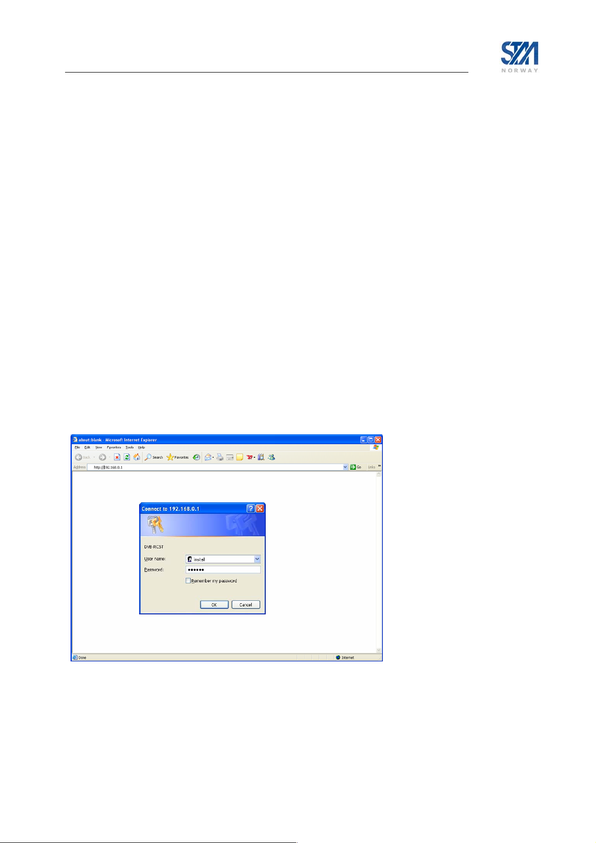
Appendix A. Using the Web Interface
The Web interface supports managing the most common configuration parameters and viewing the status
of the STM SatLink VSAT. The Web-browser currently supported is Microsoft Internet Explorer, but
other browsers like e.g. Opera 9.x normally works fine as well. The functions available via the Webinterface are:
• Viewing status information for the satellite interface
• Viewing traffic statistics
• Viewing device information
• Viewing status of the DHCP server
• Configuring the most common satellite interface parameters
• Configuring the most common IP parameters
• Return link line-up procedure
Advanced functions such as adding SW licenses, configuring GRE tunnels, downloading software
updates manually, configuring automatic software updates, configuring system information, adding users
and changing password, configuring SNMP access, and adding manual IP routes, etc, are only available
from the CLI via Telnet or the RS-232 port. If experiencing any problems using the Web interface for
management of the STM SatLink VSAT, please use the CLI via Telnet or RS-232 as a work-around for
the problem.
To manage the SatLink VSAT via the Web interface, start the web browser and type in the IP address of
the STM SatLink VSAT in the address field as shown in Figure 17 below. Use the STM SatLink VSAT’s
Satellite Interface (DVB) IP address when connecting to the VSAT over the satellite link (from the Hub),
and the STM SatLink VSAT’s LAN (Ethernet) IP address when connecting to the VSAT from the local
LAN. Then enter the username and password to logon to the VSAT.
Figure 17: Connecting to the web-interface
Copyright © 2006-2007 – STM Norway AS
Publication no. 101557, Rev. U, August 9th, 2007
Page 76
Page 77

Appendix B. Accessing the Command Line Interface via RS-232
• In some special situations the Command Line Interface via Telnet may not be accessible or will not
output the required amount of debug information. Typical examples of such situations are:
• The STM SatLink VSAT is configured with an Ethernet IP address not known to the user
• One needs to enter the boot-loader
• Detailed debugging
The Command Line Interface may then be accessed from a local PC connected to the STM SatLink
VSAT’s RS-232 interface via a serial cable. HyperTerminal or any compatible terminal emulation
program is used to access the CLI interface via RS-232. A good freeware terminal emulator is
Tera Term Pro Web 3.1.3. The software can be downloaded from Ayera home page:
http://www.ayera.com/teraterm
B.1 Cable connection
To get access to the command-line interface (CLI) via the RS-232 connection, a serial cable is connected
from the SatLink VSAT directly to a COM port on a PC:
• Plug the 9-pin connector (DB09) (male) into the rear panel of the SatLink VSAT.
• Plug the 9-pin connector (DB09) (female) into a COM port on the PC.
.
B.2 PC configuration of HyperTerminal to access the CLI via RS-232
In Windows, click the Start button and select All Programs > Accessories > Communications >
HyperTerminal. HyperTerminal will then start and the Connection Description dialogue box, shown in
Figure 18, will appear. The screen shots are from Windows XP Professional; other versions of Windows
may display differently.
Figure 18: Hyper Terminal New Connection dialogue box
Copyright © 2006-2007 – STM Norway AS
Publication no. 101557, Rev. U, August 9th, 2007
Page 77
Page 78

Enter a name and select an icon for the Connection, and click OK. The Connect To dialogue box, shown
in Figure 19, will appear.
Figure 19: Hyper Terminal Connect To dialogue box
Select the COM port where the serial cable attached to the STM SatLink VSAT is connected, and click
OK. The COM port Properties sheet will appear, as shown in Figure 20.
Figure 20: Hyper Terminal COM1 Properties sheet
Copyright © 2006-2007 – STM Norway AS
Publication no. 101557, Rev. U, August 9th, 2007
Page 78
Page 79

Use the pull-down lists to enter:
• Bits per second: 38400
• Data bits: 8
• Parity: None
• Stop bits: 1
• Flow control: none
Click Apply to accept the properties. The property sheet will close and communication with the
SatLink VSAT may begin.
Note that it may be necessary to press the enter key to display the login prompt.
When closing the session and exiting HyperTerminal, allow the program to save the session, which will
place an icon and session name into the HyperTerminal directory on the Start menu, allowing for future
quick connections.
Copyright © 2006-2007 – STM Norway AS
Publication no. 101557, Rev. U, August 9th, 2007
Page 79
Page 80

Appendix C. TFTP server
TFTPD32 is a freeware TFTP server for Windows 9x/NT/XP PCs (but seems to work on Windows 2000
as well), which is small, and easy to install and use. Use the link below and download the software.
http://tftpd32.jounin.net/
Short installation description:
1. Install the program on a PC located at either the Hub or a local LAN
2. Start the program
3. Select correct server interface if using a PC with more than one Ethernet card.
4. Select correct base directory (directory where the files to be downloaded are stored, and where
uploaded files will be stored)
5. You are up and running with a TFTP server
6. The TFTP server can now be accessed from the STM SatLink VSAT by using the CLI commands
upload and dload.
TFTP upload from and download to the STM SatLink VSAT have been tested with version 3.23 of this
TFTP server, but any TFTP server should work. It is however essential that the TFTP server has support
for negotiation of block lengths up to 8 Kbytes in order to obtain satisfactory performance over the
satellite link, in terms of acceptable download time.
The STM SatLink VSAT can access a TFTP server on both the satellite and the Ethernet interface.
Copyright © 2006-2007 – STM Norway AS
Publication no. 101557, Rev. U, August 9th, 2007
Page 80
Page 81

Appendix D. Telnet Client
A good freeware Telnet client is Tera Term Pro Web 3.1.3. The software can be downloaded from Ayera
home page: http://www.ayera.com/teraterm
recommended to use Tera Term instead of the built in Telnet Client in Windows XP, since setting Local
Echo in the Windows XP client does not seem to work.
Figure 21: Tera Term Terminal Setup
. Especially when running Telnet from Windows XP it is
When starting Tera Term, please chose the menu Setup and then Terminal. Please enable Local echo as
shown in Figure 21. Then chose the menu Setup and then Save Setup to save this configuration.
Tera Term may as well be used as a replacement for HyperTerminal.
Copyright © 2006-2007 – STM Norway AS
Publication no. 101557, Rev. U, August 9th, 2007
Page 81
Page 82

Appendix E. Management via SNMP
The STM SatLink VSAT can be monitored and managed using the standardised Simple Network
Management Protocol (SNMP).
The management information that can be collected and controlled by an SNMP management application
is contained in so-called Management Information Databases (MIBs). The STM SatLink VSAT supports
two such MIBs:
• MIB-II (relevant parts)
• STM proprietary DVB-RCS MIB
MIBs are components in the Internet Engineering Task Force (IETF) defined Structure of Management
Information (SMI) and relevant information can be found at www.ietf.org
IETF STD58 is supported.
E.1 SNMP version compliance
The SatLink VSAT supports SNMP version 2c as defined by IETF in RFC 1901 and RFC 3417.
In accordance with SNMPv2c, the access rights associated with the attached community name is checked
when an SNMP message arrives. The predefined access rights for the given community name together
with the predefined maximum access rights of the object ID(s) addressed by the SNMP message
determines the effective access rights. The STM SatLink VSAT is also equipped with optional enhanced
SNMP access control as described later.
The STM SatLink VSAT does not support traps.
. SMI version 2 as defined by
Copyright © 2006-2007 – STM Norway AS
Publication no. 101557, Rev. U, August 9th, 2007
Page 82
Page 83
E.2 MIB-II
The STM SatLink VSAT supports relevant parts of MIB-II (RFC1213). The following object groups of
MIB-II are supported:
• System
• Interface
9
• IP
• ICMP
• UDP
internet(1)
mgmt(2)
mib-II(1)
rfc-1213
system(1)
interface(2)
ip(4)
(1)...(19)
ipAddrTable(20)
ipNetToMediaTable(22)
ipForward(24)
rfc-2096
ipCidrRouteTable(4)
icmp(5)
udp(7)
Figure 22: Supported parts of MIB-II
9
ipRouteTable and ipRoutingDiscards are not supported, ipForward.ipCidrRouteTable (RFC2096) is
supported instead
Copyright © 2006-2007 – STM Norway AS
Publication no. 101557, Rev. U, August 9th, 2007
Page 83
Page 84

E.3 STM DVB-RCS MIB
E.3.1 Overview of STM DVB-RCS MIB
The STM DVB-RCS MIB contains proprietary MIB objects that together with the supported MIB-II
objects allow the complete configuration and management of the STM SatLink VSAT.
E.3.2 MIB trees for special use
In the ASN.1 MIB definition file there is special purpose objects included the following sub-trees:
• rcstSystem.sysC2P (indicated by * in the figure)
• rcstTx.txDvbSConfig (indicated by * in the figure)
• rcstOdu.oduAntenna (only some of the MIB objects)
These objects are for special purposes and are not generally available.
E.3.3 MIB object definitions
The STM DVB-RCS MIB is distributed separately in the standard ASN.1 syntax text file format used for
an IETF STD58 compliant MIB. A set of MIB objects sufficient for the STM SatLink VSAT is available
as a separate distribution. The current version of the STM DVB-RCS MIB is 200703131200Z.
enterprises(1)
stmNetworksIncMib(24386)
stmDvbRcs(50)
dvbRoot(2)
dvbSystem
sysId
sysPos
sysHW
sysSW
sysAccess
sysLog
sysCmd
sysGw
sysC2P*
sysPerformance
dvbRx
rxConfig
rxStatus
rxStatistics
dvbTx dvbOdu dvbIp dvbEthernet
txConfig
txStatus
txStatistics
txCapacity
txCw
txDvbSConfig*
oduRx
oduTx
oduAntenna
ipMulticast
ipNat
ipDhcp
ipDvbRouteTable
ipQos
ipIfAddrTable
ipPep
ipDns
ipMfc
ipIfRtn
Figure 23. The part of the STM MIB supported by the STM SatLink VSAT.
ethVlanIfTable
ethPriQosMapTable
Copyright © 2006-2007 – STM Norway AS
Publication no. 101557, Rev. U, August 9th, 2007
Page 84
Page 85

E.3.4 Support of legacy MIB
The current release of the STM SatLink VSAT supports an alternative access to many of the STM DVBRCS MIB objects through the neraDvbRcs MIB as indicated in Figure 24.
enterprises(1)
neraSatCom(3286)
neraDvbRcs(50)
neraRcst(2)
rcstSystem rcstRx rcstTx rcstOdu rcstIp
sysId
sysPos
sysHW
sysSW
sysAccess
sysLog
sysCmd
sysGw
sysC2P*
rxConfig oduRx
rxStatus oduTx
rxStatistics oduAntenna
txConfig
txStatus
txStatistics
txCapacity
txCw
txDvbSConfig*
Figure 24. Legacy MIB supported by the STM SatLink VSAT.
ipMulticast
ipNat
ipDhcp
ipDvbRouteTable
ipQos
ipIfAddrTable
ipPep
Copyright © 2006-2007 – STM Norway AS
Publication no. 101557, Rev. U, August 9th, 2007
Page 85
Page 86
E.4 Access policies
Access to the VSAT’s MIBs is limited as follows: first by a restriction based on community name and
maximum access right combination, and then optionally by the SNMP request’s source IP address and
netmask and/or source interface.
When only community name and maximum access rights limit the access, then filtering in the VSAT is
achieved by checking the SNMP message’s community name and maximum access rights only.
Otherwise also the source IP address, netmask, and/or source interface of the SNMP message is checked.
If all these parameters of the SNMP message match the values stored in the MIB object that controls the
access rights, the SNMP message is processed. Otherwise it is discarded.
The factory default configuration of the VSAT is to have configured a
read-only community named PUBLIC that is accessible from all IP
addresses and interfaces. Please note that this default community is
only available when there are no other communities defined.
E.4.1 CLI commands for configuring SNMP access
CLI commands User Privilege Level
device snmp community <name> <ro|rw> [<ipaddr> <mask>]
device snmp delcommunity <name>
device snmp show
device manager add snmp <if> [<ip> <mask>]
device manager del snmp <if> [<ip> <mask>]
device manager show
1
1
1
1
1
1
In order to use the
logged in as a user with privilege level 1 (the root user).
device snmp and device manager CLI commands one has to be
E.4.2 Access configuration
To be able to access the VSAT MIB, it is necessary to configure both the VSAT and the MIB browser
application.
1. The MIB browser application has to be configured with the correct community name both for read
access and write access.
2. The VSATs SNMP access list has to be configured via CLI, using the
command and optionally the
device manager add snmp command. It is not possible to carry out
this configuration via the web management interface of the VSAT.
Example 1:
Define an access type with the name “public”, with read-write maximum access right and with no
restriction on the SNMP request’s IP address and netmask.
# device snmp community public rw
# device snmp show
SNMP management access:
----------------------Community String Access IpAddress Subnet
public Read/Write 0.0.0.0 0.0.0.0
device snmp community
Copyright © 2006-2007 – STM Norway AS
Publication no. 101557, Rev. U, August 9th, 2007
Page 86
Page 87

Example 2:
Define an access type with name “user”, with read-only maximum access and with restriction to the
10.10.20.0 sub-net for the SNMP request source.
# device snmp community user ro 10.10.20.0 255.255.255.0
# device snmp show
SNMP management access:
----------------------Community String Access IpAddress Subnet
normal-user Read only 10.10.20.0 255.255.255.0
public Read/Write 0.0.0.0 0.0.0.0
Example 3:
Remove the access type with name “user”.
# device snmp delcommunity user
# device snmp show
SNMP management access:
----------------------Community String Access IpAddress Subnet
public Read/Write 0.0.0.0 0.0.0.0
Example 4:
Only allow SNMP access from subnet 10.10.10.0/255.255.255.0 via the satellite interface.
# device manager add snmp 3 10.10.10.0 255.255.255.0
# device manager show
Management access:
-----------------Access Interface IpAddress Subnet
SNMP 3 10.10.10.0 255.255.255.0
E.5 Setting a MIB object and saving the configuration
When the STM SatLink VSAT is shipped from the factory, the essential MIB objects of the VSAT MIB
are given default values.
When changing the value of a MIB object with write access, the new value will in general be activated
when they are set. The value will apply as long as the STM SatLink VSAT is powered on. If no special
action is taken to save the new MIB value, the value will revert to the default value upon power-on.
To save a new value so that it will survive a VSAT power off-on, one must explicitly issue a MIB save
command by setting the MIB object sysCmdSaveConfig to 1.
Saving the configuration can take up to 20 seconds.
Copyright © 2006-2007 – STM Norway AS
Publication no. 101557, Rev. U, August 9th, 2007
Page 87
Page 88

E.6 Definition of STM SatLink VSAT interface numeration
This section provides the background for the chosen numbering of the interfaces of the STM SatLink
VSAT.
The STM SatLink VSAT has two interfaces:
• The Ethernet (LAN) interface
• The satellite (DVB) interface
The Ethernet (LAN) interface of the STM SatLink VSAT has been assigned the number 1 and the Air
(DVB) interface has been given the number 3. Interface number 2 is not in use.
These interface numbers are predefined and automatically configured in the RCST.
E.7 Adding an entr y to the QoS classification table
CreateAndGo is not available when adding a new entry to the
ipQos.qosClassificationTable. Instead a new row must first be created
as CreateAndWait before being activated as shown in the example below.
E.7.1 Example - Configure an entry in the QoS classification table using MGSoft MIB browser v9.0.0.
1. Add an entry in the table by using set on the qosClassRowStatus.
Then set the value 5 (CreateAndWait) for the OID 1.3.6.1.4.1.3286.50.2.5.5.1.1.14.N where N is the
index wanted for the new entry (index 3 in the example below).
Figure 25: Define new row as CreateAndWait
Copyright © 2006-2007 – STM Norway AS
Publication no. 101557, Rev. U, August 9th, 2007
Page 88
Page 89
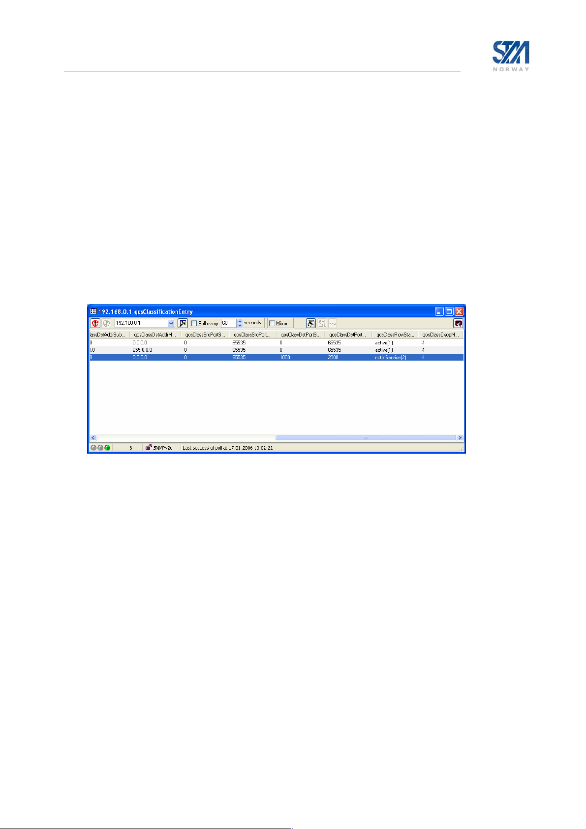
To verify that the entry is correctly created, the CLI command ip qos show may be used:
# ip qos show
QOS Policy Table
Grp Cls CrM Pri QLength Drop Timeout Description
0 0 0 0 400000 0 120 Best Effort
1 1 1 1 15000 1 120 VoIP Audio
2 1 1 2 4000 1 120 VoIP Signalling
QoS Classification table
Idx Grp Classification Parms
1 1 DSCP = 45..45
2 2 IPDst= 10.0.0.0/255.0.0.0
3 0 match all
#
2. Then use e.g. ”Table View” on the qosClassificationEntry object and edit the table. Commit the table
to the VSAT.
Figure 26: Editing the entry using "Table View"
The figure above shows an example for filtering on destination ports from 1000-2000. The entry can
be verified using the CLI command
ip qos show:
# ip qos show
QOS Policy Table
Grp Cls CrM Pri QLength Drop Timeout Description
0 0 0 0 400000 0 120 Best Effort
1 1 1 1 15000 1 120 VoIP Audio
2 1 1 2 4000 1 120 VoIP Signalling
QoS Classification table
Idx Grp Classification Parms
1 1 DSCP = 45..45
2 2 IPDst= 10.0.0.0/255.0.0.0
3 0 Dst port = 1000..2000
Copyright © 2006-2007 – STM Norway AS
Publication no. 101557, Rev. U, August 9th, 2007
Page 89
Page 90

3. Then activate the entry:
Figure 27: Activating the entry in the QoS classification table
Copyright © 2006-2007 – STM Norway AS
Publication no. 101557, Rev. U, August 9th, 2007
Page 90
Page 91

Appendix F. ODU installation
The ODU comprises the antenna with feed-horn and mounting structure, and a transceiver that contains
the LNB integrated with OMT, Tx-reject filter, and the transmitter (BUC). If the STM SatLink 4033/4035
transceiver is not used, the OMT, LNB and BUC may be supplied as two or three separate units. Two
cables with F-connectors, one for Tx and one for Rx are connecting the ODU to the IDU.
Antenna
Feed Horn
Transceiver
mounted
directly on
antenna
feed
Figure 28: STM SatLink 4033/4035 Configuration
Antenna
Reflector
F.1 Assembly of SatLink 403x transceiver to feedhorn
The STM SatLink 403x is supplied with 6 pcs of UNC 6/32 for connection to the antenna flange. The
parts are shown in the picture below. Please refer to Appendix G for information of how to connect the
STM SatLink 403x to antenna feed horn interfaces with 6 or 8 M4 screws.
Copyright © 2006-2007 – STM Norway AS
Publication no. 101557, Rev. U, August 9th, 2007
Page 91
Page 92
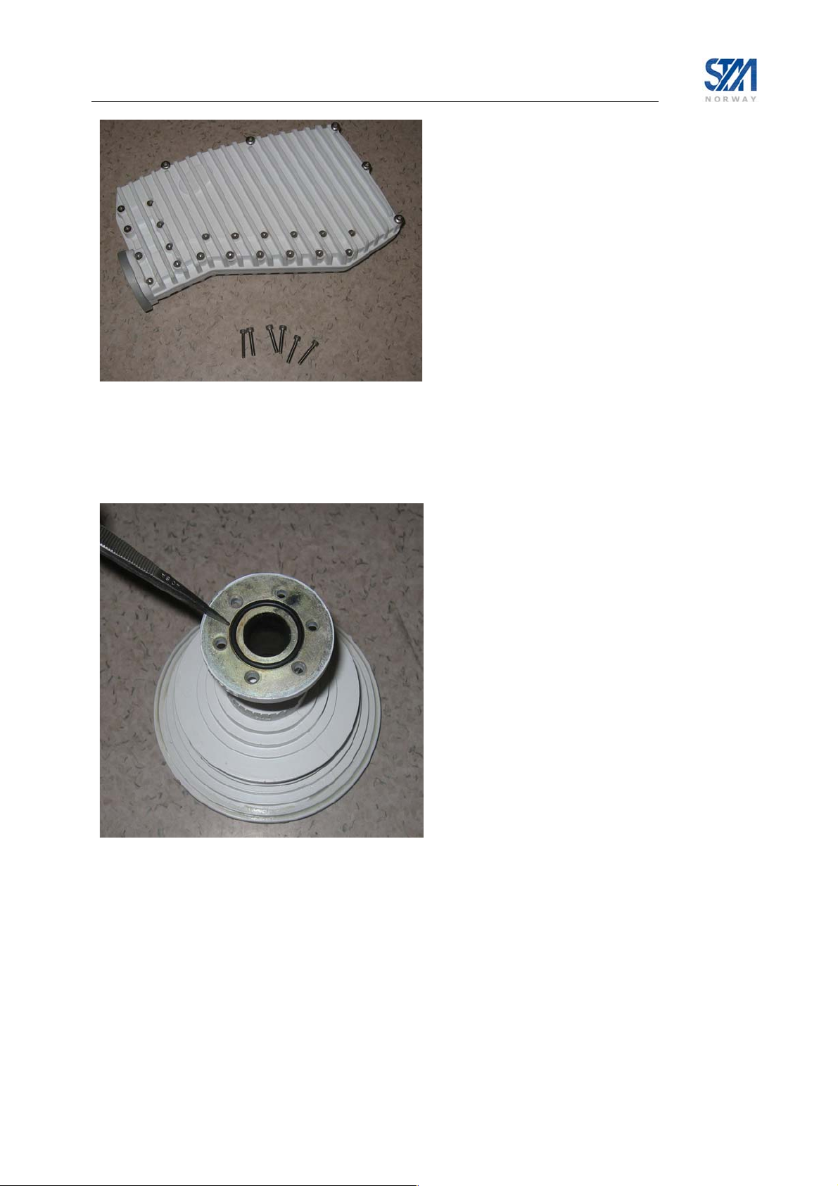
Figure 29: SatLink 4033/4035 and screws for mounting feed horn
When mounting the transceiver to the antenna horn, place the feed horn on a level surface and insert the
O-ring supplied with the antenna feed horn into the groove as shown below:
Figure 30: Inserting O-ring into feed horn groove
Place the transceiver on to the feed horn and insert one of the UNC screws for alignment. Tighten the
screw loosely by hand or with an Allen key. Make sure that the rubber gasket is not removed from the
groove when doing this.
Copyright © 2006-2007 – STM Norway AS
Publication no. 101557, Rev. U, August 9th, 2007
Page 92
Page 93

Figure 31: Mounting feed horn
Insert the remaining screws and tighten firmly with an Allen key. Always use screws from mounting kit
supplied with the STM SatLink 4033/4035 (part no. 105773). Do not use other screws or apply washers!
Figure 32: Tightening with Allen key
Copyright © 2006-2007 – STM Norway AS
Publication no. 101557, Rev. U, August 9th, 2007
Page 93
Page 94

Rx
connector
Tx
connector
Figure 33: Connecting cables from IDU
The IF connectors are placed in the chassis of the SatLink 403x. A protrusion on the case indicates ‘Rx’
and ‘Tx’ so that they are easily distinguishable. Cable connectors should be tightened firmly, but use of
excessive force may damage the F-connectors on the transceiver.
F.2 Assembly and installation of the antenna
Different mounting structures for antennas are shown below. From the left-hand side, we have an Lshaped wall-mount, a three-leg mount and a standard straight mount. The tube diameter is 76 mm. For a
correct mounting the surface must be vertical or horizontal, respectively.
Non-penetrating roof-mounting structures (requiring no screws or bolts) may also be used if the customer
do not want to penetrate the roof. The foot can be rectangular, “H-shaped” or have another suitable form.
It must be loaded with at least 75 kg depending on the antenna size and maximum wind force.
Install the antenna and adjust pointing and polarisation as described in the antenna manufacturer’s
installation instruction. After connecting the cables from the IDU to the transceiver (or BUC/LNB/OMT)
and completing the installation of the antenna with feed horn and transceiver (or BUC/LNB/OMT)
proceed with fine adjustment of antenna pointing and polarisation assisted by the IDU as described in
section 6.3.
Copyright © 2006-2007 – STM Norway AS
Publication no. 101557, Rev. U, August 9th, 2007
Page 94
Page 95

Finally, the F-connectors must be protected against rain and humidity. Use a self-vulcanising tape suitable
for out-door use. The cables must also be properly marked and should be strapped to the antenna feed
mount.
Figure 34: Complete assembled ODU with cables strapped to antenna feed mount
Important: Do not use amplifiers or attenuators on the Tx-cable.
Use type “F” connectors for the cables.
Copyright © 2006-2007 – STM Norway AS
Publication no. 101557, Rev. U, August 9th, 2007
Page 95
Page 96

The cable pulling from the ODU to the IDU must be performed according to the customer. Sharp bends
on the cables must be avoided (see figure below).
Figure 35: Avoid sharp bends on cables
Copyright © 2006-2007 – STM Norway AS
Publication no. 101557, Rev. U, August 9th, 2007
Page 96
Page 97

Appendix G. SatLink 403x. Interfacing VSAT RX/TX antennas
The STM SatLink 403x series of Ku-band transceivers is configured with internal OMT as shown in
Figure 36 below. The output interface of the transceiver (C120) is therefore connected directly to the feed
horn of the antenna.
Figure 36: STM SatLink 403x output interface (Option A)
Antenna vendors offer different variants of the feed horn for their Ku-band RX/TX
antennas. The different options are listed below.
Option Feed Horn Interface
A C120 – 6 UNC screws
B C120 – 6 or 8 M4 screws
Option A interfaces the STM SatLink 403x directly while Option B requires an adaptor in order to fit the
STM SatLink 403x output interface. The hole patterns for option A and B are shown in Figure 37 and
Figure 38.
Figure 37: Option A antenna feed
hole pattern. Holes are distributed
equally at 60 degrees apart. STM
SatLink 403x fits directly to this
pattern using 6 UNC screws for
fastening.
Copyright © 2006-2007 – STM Norway AS
Publication no. 101557, Rev. U, August 9th, 2007
Figure 38: Option B antenna feed hole pattern. Holes are
equally distributed at 45 degrees apart. Some versions have
only 6 holes. STM SatLink 403x fits on this pattern by means
of adapter STM SatLink 4901 (STM P/N 107268).
Page 97
Page 98

An overview of different antennas that can be used with the STM SatLink 403x is given in the table
below. The table shows which feed horn hole pattern (option A or B) the antenna is configured with, and
whether an adapter is required for mounting the STM SatLink 403x to the antenna feed horn. The adapter,
having model no. STM SatLink 4901, having STM P/N 107268, can be order from STM.
Manufacturer
Andrew Type 960 Class I Single offset A 0.96 m 62-96051-02 No x x
Andrew Type 960 Class I Single offset B 0.96 m 62-96052-11 STM SatLink 4901 x x
Andrew Type 960 Class II Single offset A 0.96 m 62-96055-02 No x x
Andrew Type 960 Class II Single offset B 0.96 m 62-96056-01 STM SatLink 4901 x x
Andrew Type 123 Class I Single offset A 1.20 m 62-12351-02 No x x
Andrew Type 123 Class I Single offset B 1.20 m 62-12356-11 STM SatLink 4901 x x
Andrew Type 123 Class II Single offset A 1.20 m 62-12355-02 No x x
Andrew Type 123 Class II Single offset B 1.20 m 62-12362-01 STM SatLink 4901 x x
Andrew Type 184 Dual Optics B 1.80 m 62-18452-02 STM SatLink 4901 x
Andrew Type 184 Class III Single offset B 1.80 m 62-18356-01C STM SatLink 4901 x
Andrew Type 244 Dual Optics B 2.40 m 62-24452-02 STM SatLink 4901 x
Andrew Type 244 Class III Single offset B 2.40 m 62-24356-01C STM SatLink 4901 x
Patriot
Patriot TXFCC-090KU Single offset A 0.90 m No
Patriot TX-INT100KU Single offset A 1.00 m No
Patriot TX-EUT100KU Dual Optics A 1.00 m No x
Patriot TX-INT120KU Single offset A 1.20 m No
Patriot TX-EUT120KU Dual Optics A 1.20 m No x
Patriot TX-EUT180KU Dual Optics A 1.80 m No x
Patriot TX-INT-240 Batwing A 2.40 m No
Prodelin 1123 Single offset A 1.20 m No
Prodelin 1250 Single offset A 2.40 m No
Visiosat KIT 90 EMIT Single offset A 0.90 m 0141088 No x
Visiosat KIT 120 EMIT Single offset A 1.20 m 0141143 No x
Antenna Model Description Feed horn
TXFCC-084EL
Single offset A 0.84 m No
interface
option
Ant. Size Manu-
facturer’s P/N
Adapter required
Eutel
sat
Ana
-tel
Table 13 STM supported Ku-band antennas and feed interfaces.
Antennas with feed horn interface option B are often delivered with an OMT mounted on the feed horn.
The OMT is not needed when using the STM SatLink 403x. Remove the OMT and insert adapter STM
SatLink 4901 (STM P/N 107268) as described in Appendix G.1.
Copyright © 2006-2007 – STM Norway AS
Publication no. 101557, Rev. U, August 9th, 2007
Page 98
Page 99

G.1 Mounting the feed horn interface adapter on the STM SatLink 403x
Antenna feeds with the option B hole patterns will require use of adapter kit STM SatLink 4901 (STM
P/N 107268) for interfacing the STM SatLink 403x. Use the following procedure:
1) Insert the rubber gaskets supplied with the adapter on both sides of the adapter.
2) Use the 4 UNC screws to fasten the adapter to the STM SatLink 403x flange as shown in Figure 39.
3) Fasten the STM SatLink 403x to the antenna feed horn as shown in Figure 40.
Figure 39: Mounting of adapter STM SatLink
4901 (STM P/N 107268) on STM SatLink 403x.
Remember to fit rubber gasket on both sides of
the adapter to prevent moisture intrusion.
Figure 40: Mount the antenna feed to the
adapter and fasten using M4 screws.
Fasten the adapter using 4 UNC screws supplied
with the STM SatLink 403x. Hand tighten with
Allen key.
G.2 Upgrading existing VSAT installations
When upgrading an existing VSAT site from a configuration with an antenna listed in Table 13 to a
DVB-RCS site configured with the STM SatLink 403x transceiver, the antenna will normally be
configured with a feed horn with the option B hole pattern (Figure 38) and an OMT. In order to fit the
STM SatLink 403x to the antenna from the VSAT installation, do the following:
1. Remove the OMT. This part is not used when installing the STM SatLink 403x transceiver.
2. Use the adaptor STM SatLink 4901 (STM P/N 107268) to interface the STM SatLink 403x to a feed
horn with interface C120 / 4 screws as shown in Figure 39 and Figure 40,
Alternatively, feed horns (Andrew P/N 61-00233-01) with interface option A for Andrew 96 cm and
1.2 m antennas can be ordered separately.
Copyright © 2006-2007 – STM Norway AS
Publication no. 101557, Rev. U, August 9th, 2007
Page 99
Page 100

Appendix H. IDU output power calibration with other BUCs than SatLink 403x
STM SatLink VSAT can be used together with various 3rd party BUCs for C-, Ku,- Ka-, and EHF-band.
BUCs. These BUCs do not support DiSEqC communication and do not have a power detector to measure
the actual output power from the HPA. A more complicated procedure to calibrate the Tx output power
must then be run as described below.
H.1 Calibrating the IDU output power
This section describes how to calibrate the Tx output power when using 3rd party BUCs without support
for DiSEqC and integrated power detector. Please refer to section 6.3.2 for the description of the
calibration procedure for the STM SatLink 403x.
Ensure that the STM SatLink VSAT configuration procedure in section 6.2 has been performed.
Ensure that the STM SatLink VSAT is configured to start the receiver (Rx) automatically, but not the
transmitter (Tx).
Enter the CLI command
Enter the CLI command
Enter the CLI command
Enter the CLI command
start
is set to Disabled. If the transmitter is On, use the command dvb tx logoff.
Enter the CLI command
Ensure that the Tx and Rx cables from the STM SatLink VSAT to the ODU are connected.
Restart the SatLink VSAT (issue the CLI command
STM SatLink VSAT has locked to the received carrier. The receiver has successfully acquired the
forward link when the message
Logon as the install user (user = install, factory default password = dvbrcs)
Call the control centre and have contact by phone for the following measurements.
Set up a continuous wave (CW) with the following command:
dvb tx cw on <pow> <freq>
where
pow = Transmitted IF power level from IDU in dBm.
freq
Example:
dvb tx cw on -30 14100000
will transmit a CW from the ODU output at 14.1 GHz with an IDU output power of –30 dBm from the
STM SatLink VSAT.
dvb rx autostart on to enable receiver automatic start.
dvb tx autostart off to disable transmitter automatic start.
dvb rx show. Verify that the parameter Auto start is set to Enabled.
dvb tx show. Verify that the transmitter is Off and the parameter Auto
save config to save this configuration.
restart), wait till the application has loaded and the
Forward link up is displayed (see section 6.3.1 for further details).
This is an integer in the range –30 to +10. (Start with pow= -30)
= transmitted radio frequency in kHz. The frequency is only required the first time
the CW is turned on. Subsequent adjustment of the power level can be done
without entering the frequency.
Copyright © 2006-2007 – STM Norway AS
Publication no. 101557, Rev. U, August 9th, 2007
Page 100
 Loading...