

Page 1
AN4435
Application note
Guidelines for obtaining UL/CSA/IEC 60730-1/60335-1
Class B certification in any STM32 application
Introduction
The role of safety is more and more important in electronic applications. The level of safety
requirements for components is steadily increasing and the manufacturers of electronic
devices include many new technical solutions in their designs. Software techniques for
improving safety are continuously being developed. The standards related to safety
requirements for hardware and software are under continuous development as well.
The current safety recommendations and requirements are specified in world wide
recognized standards issued by IEC (International Electrotechnical Commission), UL
(Underwriters Laboratories) and CSA (Canadian Standards Association) authorities.
Compliance, verification and certification are the focus of institutions like TUV and VDE
(mostly operating in Europe), UL and CSA (targeting mainly US and Canadian markets).
The main purpose of this application note and of the associated software X-CUBE-CLASSB
is to facilitate and accelerate user software development and certification processes for
applications based on STM32 32-bit Arm
requirements and certifications.
®
Cortex® microcontrollers subject to these
The safety package (self test library, or STL) collects a set of common tests dedicated
mainly to generic blocks of STM32 microcontrollers. The STL set is based on the unique
STM32Cube interface with specific HAL (hardware abstraction layer) services and drivers
published by ST for dedicated STM32 products. Differences are covered by product specific
tests and added settings (e.g. CPU core, RAM design, clock control).
The user can include both the STL package and dedicated HAL drivers into a final customer
project, together with additional product specific tests and settings. Implementation
examples of the STL package are available for specific products of the mainstream
STM32F0, STM32F1, STM32F3, STM32G0 and STM32G4, performance STM32F2,
STM32F4, STM32F7 and STM32H7, low power STM32L0, STM32L1, STM32L4 and
STM32L5 and wireless STM32WB Series. Specific projects (IAR™-EWARM, Keil
®
Arm
and GCC and Eclipse™ based SWSTM32 or STM32CubeIDE environment and
toolchains) are included for each example, built upon a dedicated ST evaluation board.
The common part of STL package can be reused for any other microcontroller of the STM32
family due to the unique Cube interface to the HAL services.
The user has to understand that the STL package is pre-certified for methodology and
techniques used. While the provided examples show how to integrate the STL package and
the associated FW (HAL drivers) in the application, the final implementation and
functionality always has to be verified by the certification body at the application level.
Note: STMicroelectronics develops derivative firmware supporting new products step by step.
Contact your local ST sales office to get support and the latest information about available
examples.
®
MDK-
April 2021 AN4435 Rev 9 1/71
www.st.com
1
Page 2

Contents AN4435
Contents
1 Reference documents . . . . . . . . . . . . . . . . . . . . . . . . . . . . . . . . . . . . . . . . 6
2 Package variation overview . . . . . . . . . . . . . . . . . . . . . . . . . . . . . . . . . . . 7
3 Main differences between STL packages from product point of view 10
3.1 CPU tests . . . . . . . . . . . . . . . . . . . . . . . . . . . . . . . . . . . . . . . . . . . . . . . . . 12
3.2 Clock tests and time base interval measurement . . . . . . . . . . . . . . . . . . . 12
3.3 SRAM tests . . . . . . . . . . . . . . . . . . . . . . . . . . . . . . . . . . . . . . . . . . . . . . . 12
3.4 Flash memory integrity tests . . . . . . . . . . . . . . . . . . . . . . . . . . . . . . . . . . 14
3.5 Specific aspects concerning TrustZone controller . . . . . . . . . . . . . . . . . . 15
3.6 Start-up and system initialization . . . . . . . . . . . . . . . . . . . . . . . . . . . . . . . 16
3.7 Firmware configuration parameters . . . . . . . . . . . . . . . . . . . . . . . . . . . . . 16
3.8 Firmware integration . . . . . . . . . . . . . . . . . . . . . . . . . . . . . . . . . . . . . . . . . 19
3.9 HAL driver interface . . . . . . . . . . . . . . . . . . . . . . . . . . . . . . . . . . . . . . . . . 19
3.10 Incompatibility with previous versions of the STL . . . . . . . . . . . . . . . . . . . 20
3.11 Dual core support . . . . . . . . . . . . . . . . . . . . . . . . . . . . . . . . . . . . . . . . . . . 22
4 Compliance with IEC, UL and CSA standards . . . . . . . . . . . . . . . . . . . 26
4.1 Generic tests included in STL firmware package . . . . . . . . . . . . . . . . . . . 28
4.2 Application specific tests not included in ST firmware self test library . . . 30
4.2.1 Analog signals . . . . . . . . . . . . . . . . . . . . . . . . . . . . . . . . . . . . . . . . . . . . 30
4.2.2 Digital I/Os . . . . . . . . . . . . . . . . . . . . . . . . . . . . . . . . . . . . . . . . . . . . . . . 31
4.2.3 Interrupts . . . . . . . . . . . . . . . . . . . . . . . . . . . . . . . . . . . . . . . . . . . . . . . . 32
4.2.4 Communication . . . . . . . . . . . . . . . . . . . . . . . . . . . . . . . . . . . . . . . . . . . 32
4.3 Safety life cycle . . . . . . . . . . . . . . . . . . . . . . . . . . . . . . . . . . . . . . . . . . . . 32
5 Class B software package . . . . . . . . . . . . . . . . . . . . . . . . . . . . . . . . . . . 34
5.1 Common software principles used . . . . . . . . . . . . . . . . . . . . . . . . . . . . . . 34
5.1.1 Fail safe mode . . . . . . . . . . . . . . . . . . . . . . . . . . . . . . . . . . . . . . . . . . . . 34
5.1.2 Safety related variables and stack boundary control . . . . . . . . . . . . . . . 34
5.1.3 Flow control procedure . . . . . . . . . . . . . . . . . . . . . . . . . . . . . . . . . . . . . 36
5.2 Tool specific integration of the library . . . . . . . . . . . . . . . . . . . . . . . . . . . . 37
5.2.1 Projects included in the package . . . . . . . . . . . . . . . . . . . . . . . . . . . . . . 37
2/71 AN4435 Rev 9
Page 3

AN4435 Contents
5.2.2 Start-up file . . . . . . . . . . . . . . . . . . . . . . . . . . . . . . . . . . . . . . . . . . . . . . 38
5.2.3 Defining new safety variables and memory areas under check . . . . . . 38
5.2.4 Application implementation examples . . . . . . . . . . . . . . . . . . . . . . . . . . 39
5.3 Execution timing measurement and control . . . . . . . . . . . . . . . . . . . . . . . 40
5.4 Package configuration and debugging . . . . . . . . . . . . . . . . . . . . . . . . . . . 45
5.4.1 Configuration control . . . . . . . . . . . . . . . . . . . . . . . . . . . . . . . . . . . . . . . 45
5.4.2 Verbose diagnostic mode . . . . . . . . . . . . . . . . . . . . . . . . . . . . . . . . . . . 46
5.4.3 Debugging the package . . . . . . . . . . . . . . . . . . . . . . . . . . . . . . . . . . . . . 48
6 Class B solution structure . . . . . . . . . . . . . . . . . . . . . . . . . . . . . . . . . . . 49
6.1 Integration of the software into the user application . . . . . . . . . . . . . . . . . 49
6.2 Description of start-up self tests . . . . . . . . . . . . . . . . . . . . . . . . . . . . . . . . 52
6.2.1 CPU start-up self test . . . . . . . . . . . . . . . . . . . . . . . . . . . . . . . . . . . . . . . 53
6.2.2 Watchdog start-up self test . . . . . . . . . . . . . . . . . . . . . . . . . . . . . . . . . . 54
6.2.3 Flash memory complete check sum self test . . . . . . . . . . . . . . . . . . . . . 55
6.2.4 Full RAM March-C self test . . . . . . . . . . . . . . . . . . . . . . . . . . . . . . . . . . 55
6.2.5 Clock start-up self test . . . . . . . . . . . . . . . . . . . . . . . . . . . . . . . . . . . . . . 56
6.2.6 Control flow check . . . . . . . . . . . . . . . . . . . . . . . . . . . . . . . . . . . . . . . . . 57
6.3 Periodic run time self tests initialization . . . . . . . . . . . . . . . . . . . . . . . . . . 57
6.4 Description of periodic run time self tests . . . . . . . . . . . . . . . . . . . . . . . . . 58
6.4.1 Run time self tests structure . . . . . . . . . . . . . . . . . . . . . . . . . . . . . . . . . 58
6.4.2 CPU light run time self test . . . . . . . . . . . . . . . . . . . . . . . . . . . . . . . . . . 59
6.4.3 Stack boundaries runtime test . . . . . . . . . . . . . . . . . . . . . . . . . . . . . . . . 60
6.4.4 Clock run time self test . . . . . . . . . . . . . . . . . . . . . . . . . . . . . . . . . . . . . 60
6.4.5 Partial Flash CRC run time self test . . . . . . . . . . . . . . . . . . . . . . . . . . . . 61
6.4.6 Watchdog service in run time test . . . . . . . . . . . . . . . . . . . . . . . . . . . . . 62
6.4.7 Partial RAM run time self test . . . . . . . . . . . . . . . . . . . . . . . . . . . . . . . . 62
Appendix A APIs overview. . . . . . . . . . . . . . . . . . . . . . . . . . . . . . . . . . . . . . . . . . . 66
Revision history . . . . . . . . . . . . . . . . . . . . . . . . . . . . . . . . . . . . . . . . . . . . . . . . . . . . 68
AN4435 Rev 9 3/71
3
Page 4

List of tables AN4435
List of tables
Table 1. Overview of STL packages. . . . . . . . . . . . . . . . . . . . . . . . . . . . . . . . . . . . . . . . . . . . . . . . . . 7
Table 2. Organization of the FW structure . . . . . . . . . . . . . . . . . . . . . . . . . . . . . . . . . . . . . . . . . . . . . 7
Table 3. Used IDEs and toolchains . . . . . . . . . . . . . . . . . . . . . . . . . . . . . . . . . . . . . . . . . . . . . . . . . . 8
Table 4. Structure of the common STL packages . . . . . . . . . . . . . . . . . . . . . . . . . . . . . . . . . . . . . . . 8
Table 5. Structure of the product specific STL packages . . . . . . . . . . . . . . . . . . . . . . . . . . . . . . . . . . 9
Table 6. Integration support files . . . . . . . . . . . . . . . . . . . . . . . . . . . . . . . . . . . . . . . . . . . . . . . . . . . . 9
Table 7. Compatibility between different STM32 microcontrollers . . . . . . . . . . . . . . . . . . . . . . . . . . 11
Table 8. How to manage compatibility aspects and configure STL package . . . . . . . . . . . . . . . . . . 17
Table 9. Overview of HAL drivers used by STL stack procedures . . . . . . . . . . . . . . . . . . . . . . . . . . 19
Table 10. MCU parts that must be tested under Class B compliance . . . . . . . . . . . . . . . . . . . . . . . . 27
Table 11. Methods used in micro specific tests of associated ST package . . . . . . . . . . . . . . . . . . . . 29
Table 12. Signals used for timing measurements. . . . . . . . . . . . . . . . . . . . . . . . . . . . . . . . . . . . . . . . 43
Table 13. Comparison of results . . . . . . . . . . . . . . . . . . . . . . . . . . . . . . . . . . . . . . . . . . . . . . . . . . . . 44
Table 14. Possible conflicts of the STL processes with user SW . . . . . . . . . . . . . . . . . . . . . . . . . . . . 50
Table 15. Physical order of RAM addresses organized into blocks of 16 words . . . . . . . . . . . . . . . . 55
Table 16. March C phases at RAM partial test . . . . . . . . . . . . . . . . . . . . . . . . . . . . . . . . . . . . . . . . . . 65
Table 17. Start-up . . . . . . . . . . . . . . . . . . . . . . . . . . . . . . . . . . . . . . . . . . . . . . . . . . . . . . . . . . . . . . . . 66
Table 18. Run time . . . . . . . . . . . . . . . . . . . . . . . . . . . . . . . . . . . . . . . . . . . . . . . . . . . . . . . . . . . . . . . 67
Table 19. Document revision history . . . . . . . . . . . . . . . . . . . . . . . . . . . . . . . . . . . . . . . . . . . . . . . . . 68
4/71 AN4435 Rev 9
Page 5

AN4435 List of figures
List of figures
Figure 1. HSEM IDs distribution and control . . . . . . . . . . . . . . . . . . . . . . . . . . . . . . . . . . . . . . . . . . . 24
Figure 2. Example of RAM configuration . . . . . . . . . . . . . . . . . . . . . . . . . . . . . . . . . . . . . . . . . . . . . . 35
Figure 3. Control flow four steps check principle . . . . . . . . . . . . . . . . . . . . . . . . . . . . . . . . . . . . . . . . 37
Figure 4. Diagnostic LED timing signal principle . . . . . . . . . . . . . . . . . . . . . . . . . . . . . . . . . . . . . . . . 40
Figure 5. Typical test timing during start-up . . . . . . . . . . . . . . . . . . . . . . . . . . . . . . . . . . . . . . . . . . . . 41
Figure 6. Typical test timing during run time . . . . . . . . . . . . . . . . . . . . . . . . . . . . . . . . . . . . . . . . . . . 42
Figure 7. Hyper terminal output window in verbose mode - Single core products. . . . . . . . . . . . . . . 47
Figure 8. Hyper terminal output window in verbose mode - Dual core products . . . . . . . . . . . . . . . . 47
Figure 9. Integration of start-up and periodic run time self tests into application . . . . . . . . . . . . . . . . 49
Figure 10. start-up self tests structure . . . . . . . . . . . . . . . . . . . . . . . . . . . . . . . . . . . . . . . . . . . . . . . . . 52
Figure 11. CPU start-up self test structure. . . . . . . . . . . . . . . . . . . . . . . . . . . . . . . . . . . . . . . . . . . . . . 53
Figure 12. Watchdogs start-up self test structure . . . . . . . . . . . . . . . . . . . . . . . . . . . . . . . . . . . . . . . . 54
Figure 13. Flash start-up self test structure . . . . . . . . . . . . . . . . . . . . . . . . . . . . . . . . . . . . . . . . . . . . . 55
Figure 14. RAM start-up self test structure . . . . . . . . . . . . . . . . . . . . . . . . . . . . . . . . . . . . . . . . . . . . . 56
Figure 15. Clock start-up self test subroutine structure . . . . . . . . . . . . . . . . . . . . . . . . . . . . . . . . . . . . 57
Figure 16. Periodic run time self test initialization structure . . . . . . . . . . . . . . . . . . . . . . . . . . . . . . . . . 58
Figure 17. Periodic run time self test and time base interrupt service structure . . . . . . . . . . . . . . . . . 59
Figure 18. CPU light run time self test structure . . . . . . . . . . . . . . . . . . . . . . . . . . . . . . . . . . . . . . . . . 59
Figure 19. Stack overflow run time test structure. . . . . . . . . . . . . . . . . . . . . . . . . . . . . . . . . . . . . . . . . 60
Figure 20. Clock run time self test structure . . . . . . . . . . . . . . . . . . . . . . . . . . . . . . . . . . . . . . . . . . . . 61
Figure 21. Partial Flash CRC run time self test structure . . . . . . . . . . . . . . . . . . . . . . . . . . . . . . . . . . . 61
Figure 22. Partial RAM run time self test structure . . . . . . . . . . . . . . . . . . . . . . . . . . . . . . . . . . . . . . . 63
Figure 23. Partial RAM run time self test - Fault coupling principle (no scrambling) . . . . . . . . . . . . . . 64
Figure 24. Partial RAM run time self tests - Fault coupling principle (with scrambling) . . . . . . . . . . . . 64
AN4435 Rev 9 5/71
5
Page 6
Reference documents AN4435
1 Reference documents
Several ST documents can be used when applying or modifying the STL stack or when
developing a new one, and complete testing report can be provided upon request.
Specific safety manuals for STM32 products (based on Arm
preparation, where compliance aspects with other safety standards are provided.
plication notes describing specific methods to control peripherals or to ensure system
Ap
electromagnetic compatibility (EMC) against noise emission and noise sensitivity are
available on www.st.com.
For more information about errors handling techniques refer to Handling of soft errors in
STM32 applications (AN4750).
For more information on EMC refer to the following application notes:
Softwa
EMC design guide (AN1709)
For more detailed information about cyclic redundancy check calculation (CRC) refer to
Using the
re techniques for improving microcontroller EMC performance (AN1015)
CRC peripheral in STM32 family (AN4187).
(a)
cores) are available or in
The following safety manuals are available on ww
UM17
UM1814 (for the F1 Series)
UM1845 (for the F2 Series)
UM1846 (for the F3 Series)
UM1840 (for the F4 Series)
UM2318 (for the F7 Series)
UM2455 (for the G0 Series)
UM2454 (for the G4 Series)
UM2331 (for the H7 Series)
UM2037 (for the L0 Series)
UM1813 (for the L1 Series)
UM2305 (for the L4 and L4+ Series)
UM2752 (for the L5 Series)
The development of safety manuals for other Series is an ongoing process. Contact your
al FAE or the nearest ST office to check for the availability of new documents.
loc
41 (for the F0 Series)
w.st.com:
a. Arm is a registered trademark of Arm Limited (or its subsidiaries) in the US and/or elsewhere.
6/71 AN4435 Rev 9
Page 7
AN4435 Package variation overview
2 Package variation overview
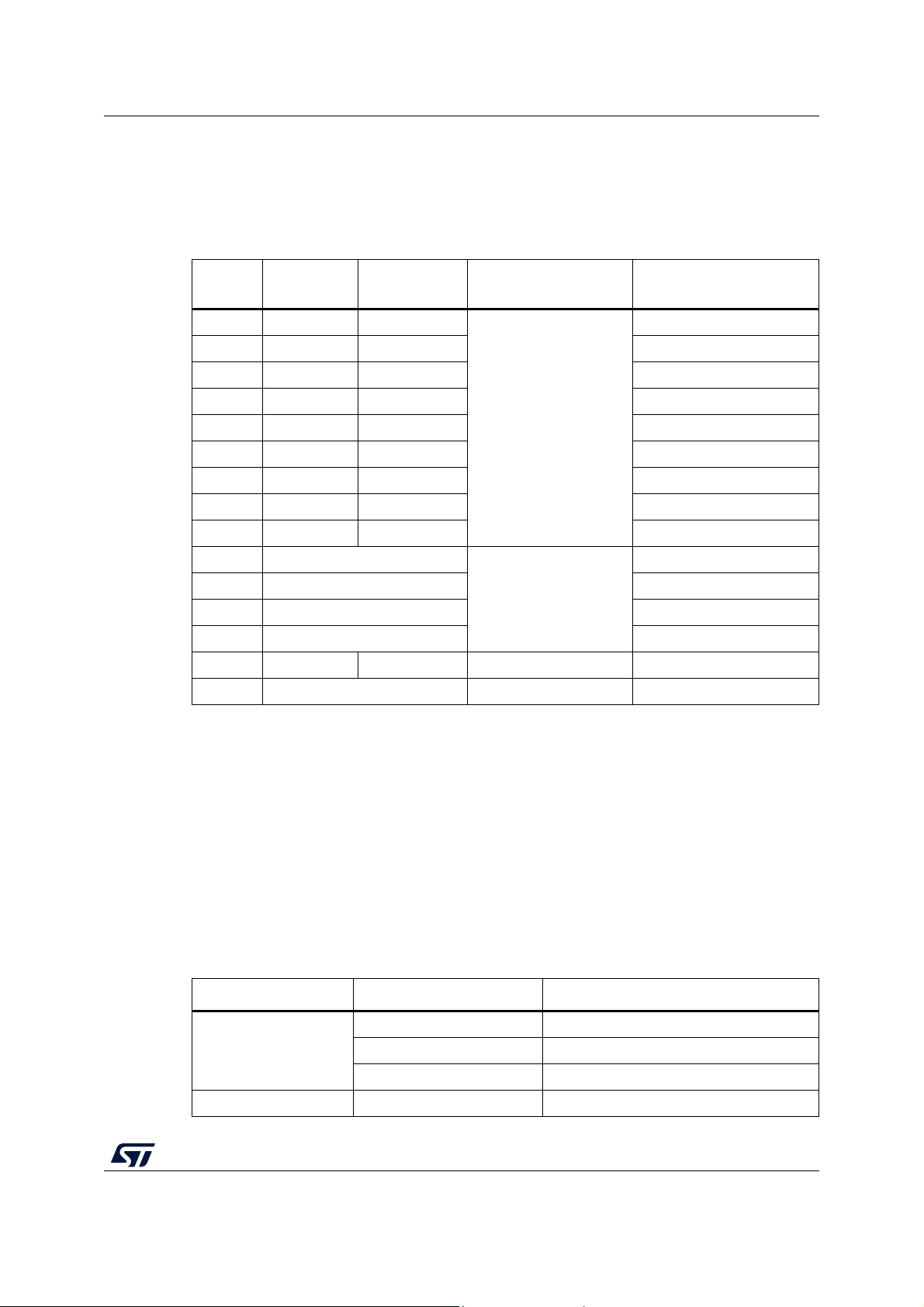
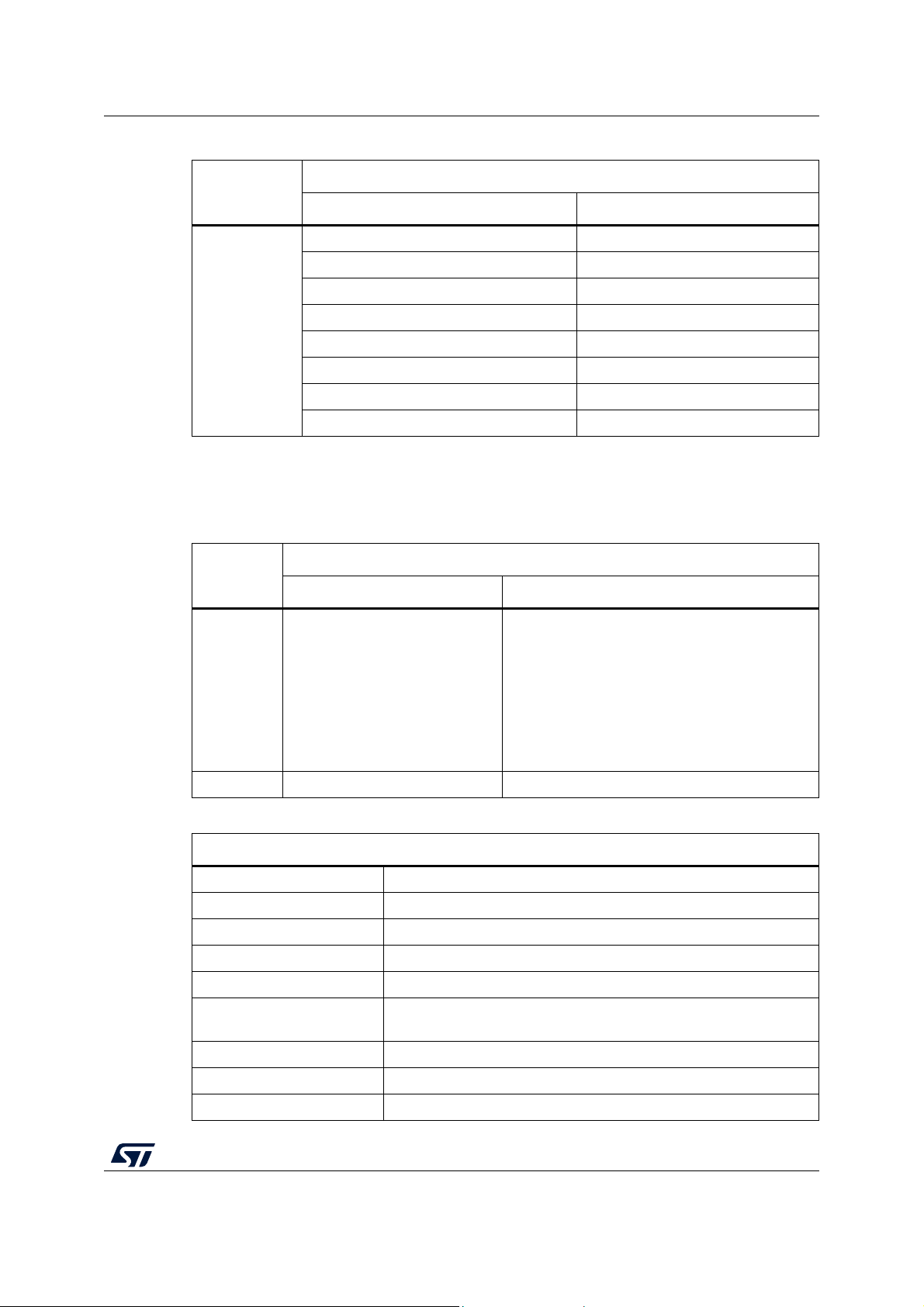
The STL packages and included HAL FW are summarized in Tab le 1.
Table 1. Overview of STL packages
STM32
Series
HAL driver CMSIS driver
F0 Rev. 1.5.0 Rev. 2.3.1
Common STL stack
Specific test
(1)
Included projects
SMT32052B-EVAL
F1 Rev. 1.1.1 Rev. 4.2.0 STM3210C-EVAL
F2 Rev. 1.2.1 Rev. 2.2.0 STM322xG_EVAL
F3 Rev. 1.4.0 Rev. 2.3.1 SMT32373C-EVAL
F4 Rev. 1.7.1 Rev. 2.6.1 STM324xG_EVAL
Rev. 2.2.0
F7 Rev. 1.2.2 Rev. 1.2.0 STM32756G-EVAL
L0 Rev. 1.8.1 Rev. 1.7.1 STM32L0xx_Nucleo
L1 Rev. 1.3.0 Rev. 2.2.1 STM32L152D-EVAL
L4 Rev. 1.7.1 Rev. 1.3.1 STM32L476G-EVAL
H7 Rev. 1.5.0
STM32734I-EVAL
G0 Rev. 1.2.0 STM32G081B-EVAL
Rev. 2.3.0
G4 Rev. 1.0.0 STM32G474RE_NUCLEO
WB Rev. 1.1.0 P-NUCLEO-WB55
L5 Rev 1.3.0 Rev 1.0.3 Rev 2.4.0 STM32L552ZE_Nucleo
(2)
H7
1. There are negligible differences between the STL stack versions. For more details refer to the firmware
release notes. The stack modifications needed when user migrates and combines older versions of the
stack with the latest HAL drivers and compilers are described in Section 3.10.
2. Support for dual core products.
Rev 1.9.0 Rev 3.0.0 STM32H747I-DISCO
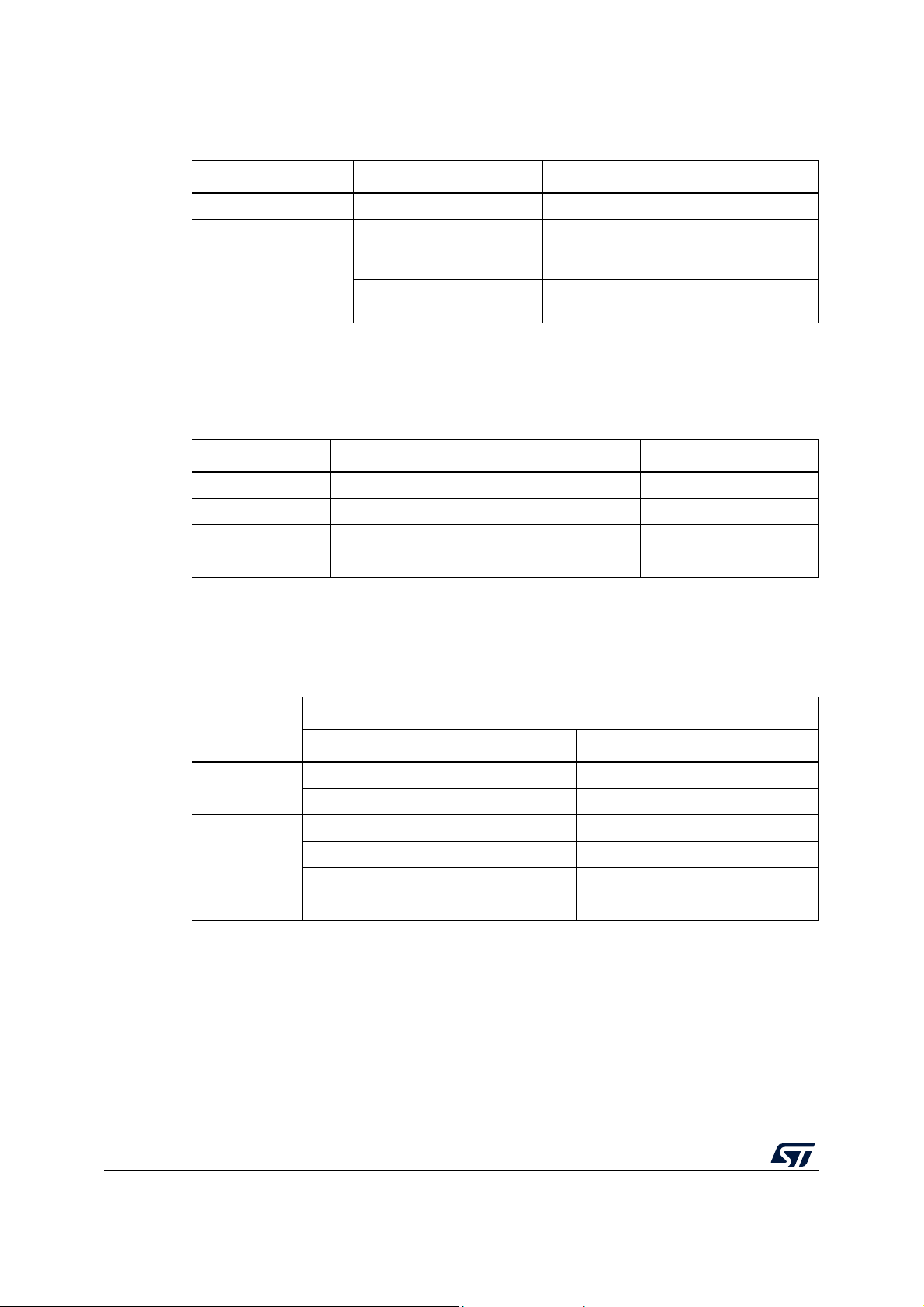
The firmware uses a common structure of directories. It is based on available set of drivers
either dedicated to a given product, or associated with specific HW development tools. Part
of that is common with the whole STM32 family and ST debug support.
The basic structure is detailed in Table 2, where self test procedures and methods targeting
the Class B requirements are collected under common STL stack and product specific STL
stack directories. The remaining drivers are mostly application specific, and are subject to
change or replacement in the final customer project, in accordance with user application
HW.
Directory Drivers Comment
Drivers
Utilities CPU, Fonts, Log Common debug/development support
Table 2. Organization of the FW structure
BSP Evaluation board specific drivers
CMSIS Core specific drivers
HAL Product specific peripheral drivers
AN4435 Rev 9 7/71
70
Page 8
Package variation overview AN4435
Table 2. Organization of the FW structure (continued)
Directory Drivers Comment
Middleware Common STL stack Common STM32 STL procedures
Product and tools dependent specific
Projects/xxxxxx_EVAL
or
Projects/xxxxxx_Nucleo
Integration example
Product Specific STL stack
procedures and configurations of
evaluation board and integration example
Product and tools dependent STL
procedures and configurations
The included projects for specific STM32 products and dedicated evaluation boards have
been prepared and tested with the environments and toolchains detailed in
IDE STL Rev. 2.2.0 STL Rev. 2.3.0 STL Rev. 2.4.0 and 3.0.0
IAR™ EWARM Rev. 7.80.4 Rev. 8.32.4 Rev. 8.40.2
Keil® MDK-Arm
®
Eclipse™ Rev. 1.13.1 Rev. 1.17.0 2019-09 CDT Rev. 9.9.0
Table 3. Used IDEs and toolchains
Rev. 5.23 Rev. 5.27 Rev. 5.31
Tabl e 3.
STM32CubeIDE - Rev. 1.0.0 Rev. 1.4.2
The detailed structure of these projects and the list of files included in the common and
specific parts of STL stack are summarized in
Tabl e 4 and Tab l e 5, respectively. Additional
supporting files used in the examples are listed in Tab le 6.
STL
Start-up test
Run time test
Table 4. Structure of the common STL packages
Common STL stack source files
File Description
(1)
(1)
Start-up STL flow control
Run time STL flow control
stm32xx_STLstartup.c
stm32xx_STLclockstart.c Clock system initial test
stm32xx_STLmain.c
stm32xx_STLclockrun.c Partial clock test
stm32xx_STLcrc32Run.c Partial Flash memory test
stm32xx_STLtranspRam.c Partial RAM test
8/71 AN4435 Rev 9
Page 9
AN4435 Package variation overview
Table 4. Structure of the common STL packages (continued)
Common STL stack source files
STL
File Description
stm32xx_STLclassBvar.h Definition of Class B variables
stm32xx_STLlib.h Overall STL includes control
stm32xx_STLstartup.h Initial process STL header
Headers
1. As version 3.0.0 supports dual core products, files stm32xx_STLstartup.c and stm32xx_STLmain.c are
replaced by, respectively, stm32_STLstartup_DualCore.c and stm32xx_STLmain_DualCore.c.
Files stm32_STLcrcSW.c, stm32_STLcrcSWRun.c, and stm32_STLcrcSW.h, are included additionally into
the STL common package to support software CRC calculation on the Flash memory by the secondary
core.
stm32xx_STLmain.h Run time process STL header
stm32xx_STLclock.h Clock test header
stm32xx_STLcpu.h CPU test header
stm32xx_STLcrc32.h Flash memory test header
stm32xx_STLRam.h RAM test header
Table 5. Structure of the product specific STL packages
Product specific STL stack source and header files
STL
Files Description
stm32xxxx_STLcpustartIAR.s
stm32xxxx_STLcpurunIAR.s
stm32xxxx_STLRamMcMxIAR.s
Source
stm32xxxx_STLcpustartKEIL.s
stm32xxxx_STLcpurunKEIL.s
stm32xxxx_STLRamMcMxKEIL.s
Start-up and run time CPU and RAM tests written
in Assembler for IAR™, Keil® and GCC
stm32xxxx_STLcpustartGCC.s
stm32xxxx_STLcpurunGCC.s
stm32xxxx_STLRamMcMxGCC.s
Header stm32xxx_STLparam.h STL product specific configuration file
Table 6. Integration support files
Files supporting implementation of STL in the integration example
startup_stm32xxxxxIAR.s C start-up for IAR™ compiler
startup_stm32xxxxxKEIL.s C start-up for Arm® compiler
startup_stm32xxxxxGCC.s C start-up for GCC compiler
main.c Main flow of the example source
stm32xxxx_hal_msp.c Application specific HAL drivers initialization
stm32xxxx_it.c
STL Interrupts, clock measurement processing and configuration
procedures
main.h Main flow header
stm32xxxx_hal_conf.h HAL drivers configuration file
stm32xxxx_it.h ISR header
AN4435 Rev 9 9/71
70
Page 10
Main differences between STL packages from product point of view AN4435
3 Main differences between STL packages from
product point of view
Users can find some small differences, mainly due to hardware differences between the
products and to incompatibilities of compilers and debugging tools.
The main differences are due mainly to compatibility aspec
products, all based on Arm
These differences, summarized in Tab le 7, are described in this section.
®
cores.
ts between different STM32
10/71 AN4435 Rev 9
Page 11
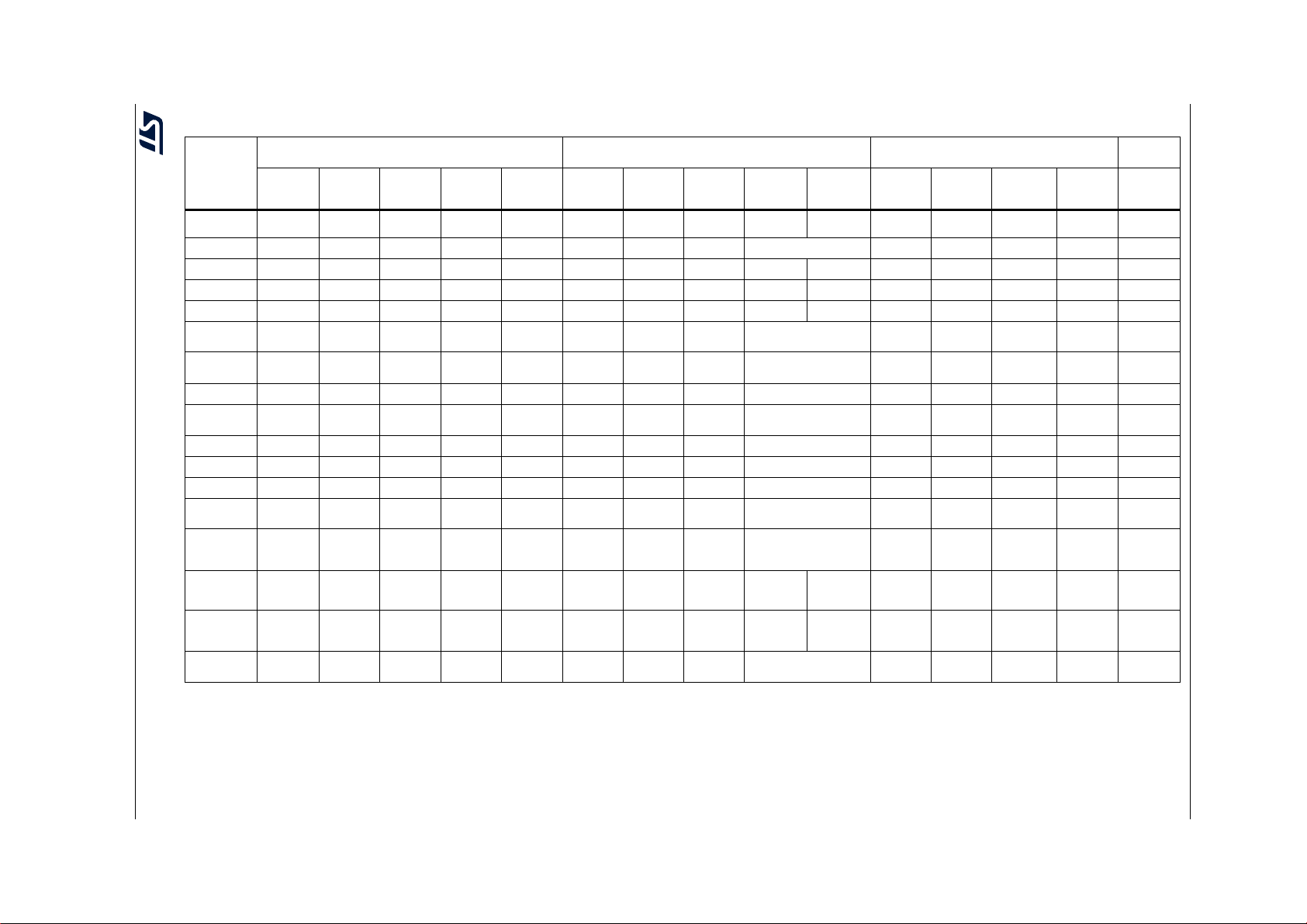
Table 7. Compatibility between different STM32 microcontrollers
STM32
Series
Arm® Cortex
core(s)
Technology 180 nm 180 nm 90 nm 90 nm 90 nm 180 nm 90 nm 90 nm 40 nm 110 nm 130 / 110 nm 90 nm 90 nm 90 nm
Frequency 48 MHz 24-72 MHz 120 MH z 64 MHz 150 MHz 72 MHz 168 MHz 216
Performance 38 DMIPS 61 DMIPS 150 DMIPS 59 DMIPS 190 DMIPS 61 DMIPS 210 DMIPS 462 DMIPS 856 DMIPS 1327 DMIPS 26 DMIPS 33 DMIPS 100 DMIPS 165 DMIPS DMIPS
Flash memory 16-128 KB 16-1024 KB 128-1024 KB 16-512 KB 128-1024 KB 32-256 KB 128-2048 KB 512-2048 KB 128-2048 KB 2048 KB 32-192 KB 32-512 KB 128-1024 KB 256-512 KB 256-1024 KB
ECC on
Flash memory
CRC
configurable
RAM 4-16 KB 4-96 KB 64-128 KB 8-128 KB 32-128 KB 16-48 KB 64-256 KB 256-512 KB 1024 KB 8-20 KB 4-80 KB 4-320 KB 256 KB 256 KB
AN4435 Rev 9 11/71
RAM parity
/scrambling
Auxiliary RAM No No Yes No CCM RAM
Data EEPROM - - - - - - - - - 2 KB 2-16 KB - - -
EEPROM ECC - - - - - - - - - Yes Yes - - -
IWDG
window option
Clock system
Clock cross
reference
measurement
Clock reference
next options
Voltage scaling
management
1. Available on some products only.
2. When product features SRAM parity bit, address is included, except the STM32F0 Series where parity is computed only over data.
3. Parity bit does not cover the whole RAM, but only a portion of it. Check the product datasheet for detailed info.
4. Embedded RAM features ECC.
5. All the family members feature HSI16, HSE, PLL, LSI and LSE clock sources. Additional sources are listed in the table.
6. Timers dedicated to clock cross reference measurements are 16-bit wide, except STM32F2, STM32F4, STM32F7 and TIM5 of STM32G4, where 32-bit ones are used.
7. TIM16/Ch1 is used for STM32F30xx.
F0 F1 F3 G0 G4 F2 F4 F7 H7
®
M0 M3 M4 M0+ M4 M3 M4 M7 M7 M7 and M4 M0+ M3 M4 M33 M4
No No Yes
Yes No No Yes Yes Yes No Yes Yes Yes No Yes Yes Yes
(2)
Yes /Ye s N o/ Ye s N o/ No Yes /N o Yes
Yes No No Yes Yes Yes No Yes Yes Yes No Yes Yes Yes
HSI14, HSI48
(5)
(LSI~40 kHz)
TIM14/Ch1 TIM5/Ch4
(6)
GPIO, RTC,
HSE/32,
Yes
(LSI~40 kHz) (LSI~32 kHz) (LSI~32 kHz)
MCO
(1)
Mainstream Performance Low-power Wireless
(1)
MHz 400 MHz 480/240 MHz 32 MHz 32 MHz 80 MHz 110 Mhz 64 MHz
(1)
TIM5/Ch4
GPIO, RTC,
LSI, LSE
No Yes
(1)
(1)
Yes Yes Yes
(3)
/No No/No No/No No/No No
(1)
HSI48
(LSI~32 kHz)
(7)
TIM16/Ch1 TIM16/Ch1 TIM14/Ch1 TIM5/Ch4 TIM5/Ch4 TIM16/Ch1 TIM16/Ch1 TIM21/Ch1 TIM10/Ch1 TIM16/Ch1 TIM16/Ch1 TIM16/Ch1
LSE,
MCO
MCO HSE/32
RTC LSE
HSE/32,
Yes Yes Yes Yes Yes Yes Yes Yes Yes Yes Yes
(1)
CCM RAM
No External only Yes, embedded CRC unit Yes No Yes Yes Yes
(1)
Yes Yes TCM, backup No No Yes Backup Backup
(LSI~40 kHz) (LSI~32 kHz) (LSI~32 kHz) CSI, HSI48, (LSI~32 kHz)
GPIO, RTC,
HSE/32,
MCO
GPIO, RTC,
LSI, LSE
GPIO, RTC,
LSI, LSE
LSE CSI
HSE_1MHz
MCO1, MCO2
H7 dual
core
(4)
/No No/No No/No Yes
LSE CSI
HSE_1MHz
MCO1, MCO2
L0 L1 L4 L5 WB
MSI, HSI48
(LSI~38 kHz)
GPIO, MSI,
LSI, LSE
HSE_RTC
MSI
(LSI~38 kHz)
GPIO, RTC,
LSI, LSE
(3)
/No Yes
MSI, HSI48
(LSI~32 kHz)
GPIO, RTC,
LSI, LSE, MSI,
HSE/32, MCO
(1)
(3)
/No Yes
MSI, HSI48
(LSI~32 kHz)
LSE, RTC
(3)
/No
MSI, HSI48
(LS1/2I~32
kHz)
LSE RTC
MSI HSE/32
MCO
AN4435 Main differences between STL packages from product point of view
(1)
Page 12

Main differences between STL packages from product point of view AN4435
3.1 CPU tests
Some specific operations are inaccessible by high level compilers. That is why code for both
start-up and run time tests are written in assembly, and differs slightly in mnemonics among
used compilers.
These tests are product dependent, as sets of available instructions differ between Cortex®
cores used by STM32 microcontrollers. As an example, due to restricted instruction set of
®
Arm
Cortex®-M0+ core, instructions loading immediate 32-bit constant operands are
replaced by instructions loading those constants placed at code memory.
When user applies a contemporary version of compiler to an older version of the STL, the
assembly testing routine applied at startup can become incompatible and require
adaptations. For more information refer to
versions of the STL.
Section 3.10: Incompatibility with previous
3.2 Clock tests and time base interval measurement
Internal timers are used to cross-check frequency measurements. This method is required
to determine harmonic or sub-harmonic frequencies when the system clock is provided by
an external crystal or ceramic resonator, or to detect any significant discrepancy in the
application timing. Different product dependent timers are dedicated to perform such cross
check measurement.
Initial configuration of the specific timers is slightly different while dedicated interrupt vectors
are used for the measurement in dependency on concrete timer at given device.
Some older products do not support cross-reference measurement feature.
If the system clock doesn't use the HSE quartz clock, user can set up the clock
measurement HSI vs. LSI commenting out the parameter HSE_CLOCK_APPLIED in the
stm32xx_STLparam.h file or adapting the clock measurement to be based on another
reliable clock source (e.g. line power frequency) to satisfy the standard requirements for the
clock monitoring.
In any case, if the cross check measurement depends upon the RC clock (HSI or LSI), user
has to consider the accuracy of such a clock source over the whole temperature range. This
is necessary to prevent any false clock failure detection, especially when the unit under self
test has to operate over a wider temperature range. User can apply an adaptable clock test
algorithm while monitoring the trend of the ambient temperature, or consider a more
accurate source to be taken as a clock reference.
Clock security system hardware feature (CSS) is activated by default by the library during
startup test as a supplementary testing method if HSE is used as system clock (see
stm32xx_STLclockstart.c file).
3.3 SRAM tests
Hardware techniques that ensure single bit redundancy protection of both data words and
their addresses are the minimum requirement to fulfill the associated standards on volatile
memories (to detect errors not only in areas dedicated to data, but also on their internal
address and data path). Some of the older ST products do not feature this (partial or full)
hardware redundancy, and then these requirements shall to be met indirectly by applying
proper software methods, better if in combination with hardware.
12/71 AN4435 Rev 9
Page 13

AN4435 Main differences between STL packages from product point of view
Unfortunately, execution of these tests uses a portion of microcontroller computing power,
and makes overall diagnostic tests longer. As a consequence, software methods are
applicable on static errors only. Even very sophisticated tests are not able to cover transient
errors efficiently, so their diagnostic coverage is limited.
The SRAM test must follow a topological pattern. Testing by word can be used as logically
adjacent bits (belonging to a single word) are physically far away from each other split in the
array, while pairs of words with subsequent logical addresses share physically adjacent
neighbor cells (bits). In addition, when the sequence of addresses is not regular (as in some
older STM32 products), the physical order of words addresses (so called scrambling) has to
be respected during this test.
User has to ensure that a proper test corresponding to the RAM design is implemented for
the product used in the application. This is done by definition of ARTISAN symbol for the
assembly compiler. This symbol has to be defined for STM32F0xx, STM32F1xx and
STM32F3xx products exclusively.
Optionally, user can simplify and speed-up the Marching C- algorithm used during run time
testing when USE_MARCHX_TEST symbol is applied. If this symbol is defined, two middle
marching steps are skipped and not implemented during the transparent test (see
Section 6.4.7: Partial RAM run time self test). It is suggested to keep full March C- algorithm
at least during the initial test.
Some ST microcontrollers feature a built-in word protection with single bit redundancy
(hardware parity check) applied on CCM RAM or at least on a part of the SRAM. This
hardware protection is one of the acceptable methods required by the IEC
IEC
60730. The built-in parity feature includes address and data with the exception of the
60335 and
STM32F0 Series, where the parity is only computed with the data.
Despite the hardware method is recognized by the standard, it is advised to keep the
execution of software March test and the data redundancy as supplementary safety
methods for the volatile memory testing, and not to rely exclusively on the hardware (the
main reason is that there is no way how to test functionality of the parity feature during run
time).
Reliability of the information stored in the SRAM can be increased by applying additional
indirect testing techniques, such as double storage of safety critical information in physically
separated areas in the form of two inverted patterns (this is based on the fact that corruption
caused by radiation or EMI usually attacks a limited physical memory section), or by
applying dedicated check sum signature to each part of these data.
The hardware RAM parity check is an optional feature. When enabled, it is advised to
perform a SW initialization of the whole RAM at the beginning of the code execution, to
avoid getting parity errors when reading non-initialized locations (this is the case of local
variables when they are allocated and read out while using different data access to
memory). The best way to do this is during start-up procedure. A simple loop inserted into
start-up assembly code can solve the problem and initialize parity system in the dedicated
RAM area:
; Program starts here after reset
;------------------------------------------------------------------------
Reset_Handler
; Parity system initialization has to be performed here prior to the
; startup self-test procedure
AN4435 Rev 9 13/71
70
Page 14

Main differences between STL packages from product point of view AN4435
;------------------------------------------------------------------------
; r0 is used as a pointer to RAM,
; r1 keeps end address of the area
;------------------------------------------------------------------------
;At every step of the loop, the 32-byte block (r2-r9) is copied to RAM
; starting from address kept at r0, r0 is then increased by 32
; the loop body is performed while r0<r1
LDR R0, =RAM_block_begin
ADD R1, R0, #RAM_block_size
RAM_init_loop
STMIA R0!, {R2-R9}
CMP R0, R1
BLT RAM_init_loop
; RAM is initialized now, program can continue by startup self-test
LDR R0, =STL_StartUp
BLX R0
Note: The real content of the registers copied by STMIA instruction is not relevant because the
purpose of this loop is to initialize the parity system. The RAM content is initialized at a later
stage by the compiler standard start-up procedure. RAM_block_begin, RAM_block_size
and end memory address setting must be aligned with the number of data copied by STMIA
instruction to prevent any undefined memory access, especially at the end of the loop.
Note: For new products featuring optional HW initialization of the SRAM, there is no need to
perform initialization of the memory by the upper SW loop if the user activates this option.
When the initial software March test is performed over a RAM area dedicated to stack, it
destroys all the stack content including the return address of the test routine itself stored
there when high level compiler is used. The store and restore procedure of the return
address depends on the compiler implementation and can differ for different optimization
levels. Besides an optimization effort, this is main reason why the routines supporting SRAM
testing are written in assembly, to be independent from the higher compiler implementation.
On the other side this solution brings a light tool dependency, and different assembly source
files have to be kept to pass their compilation correctly.
When user applies a contemporary version of compiler to older version of the STL the
assembly testing routine applied at startup can become incompatible and require small
adaptations. For more information see
Section 3.10: Incompatibility with previous versions
of the STL.
3.4 Flash memory integrity tests
Flash memory test is based on built-in HW CRC unit. Some of the STM32 microcontrollers
feature configurable units so that the initial configuration can differ slightly, however the
polynomial calculation used is the same for all the products.
User must comment definition of parameter CRC_UNIT_CONFIGURABLE in the
stm32xx_STLparam.h configuration header file for all products where CRC is not
configurable.
The area where the pattern of CRC calculation is stored has to be excluded from the range
of the calculation. The boundaries of the checked area must be aligned with multiples of
14/71 AN4435 Rev 9
Page 15

AN4435 Main differences between STL packages from product point of view
tested block size used during the test. By default, the block size is set to 16 words (64 bytes)
by parameter FLASH_BLOCK_WORDS defined in the stm32xx_STLparam.h file. Unused
memory areas included in the check have to be identified with predefined values. An all-1
pattern is used by default.
The range under the nonvolatile memory test is defined by the user. During run time, if the
test of the overall memory range is not acceptable because too long, the user can split it into
segments that correspond to local areas where the program is being executed. This
requires to dynamically modify the area under test, so that the testing is performed
exclusively over those areas.
The STL integration examples perform tests of single contiguous areas described by single
check sum descriptor. When user considers additional separated segments, the test
procedure has to be adapted, as done in the X-CUBE-STL library targeting SIL.
The result of the CRC calculation has to be compared with the corresponding reference
pattern provided either automatically by compiler (IAR™ case) or added by the end user
from a computation handled externally (MDK-Arm
®
and GCC cases).
When the tool does not support CRC pattern placement, specific script files
(crc_gen_keil.bat or crc_gen_gcc.bat) are provided in the implementation example projects
to run post-built procedures calculating the check sum automatically. They are based on
installation of Srecord GNU tool, freely available from http://srecord.sourceforge.net. Default
HEX file provided by the linker output is modified and the CRC reference pattern is inserted
in a new HEX file. User has to ensure that the modified HEX file (output_name_CRC.hex) is
used for the application download (e.g. by implementation of crc_load.ini file or by proper
modification of launch configuration properties when debug or download session starts).
When testing the Flash memory integrity, CRC computation done via hardware CRC
generator decreases significantly the CPU load. The Flash memory can be tested while
DMA is used for feeding CRC block, too. In comparison with software test, the CPU load
decreases significantly when DMA is applied but the speed of the test itself doesn't change
so much, because DMA needs at least a few cycles to read and transfer data. The test can
even slow down when DMA services some other transfers or interrupts in parallel. Moreover
some additional DMA configuration is required at initialization of the test. User can find
detailed information about use of DMA for CRC calculation in AN4187.
Some of the oldest STM32 devices do not feature the CRC hardware block and use
software routines for CRC computation. Former versions of the STL based on obsolete SPL
libraries provide 16-bit wide calculation method based on predefined look-up table constants
to speed up the calculation.
3.5 Specific aspects concerning TrustZone controller
When dealing with TrustZone security controller (used by STM32L5 Series, based on the
security-oriented Arm
areas is to be handled with care.
No issues are expected for CPU registers used for the test, common for both the secure and
non-secure execution state, except for register R13, which is kept separately (the one
related to the ongoing state is for test only). This is also the case for memory regions when
the associated tests are applied at the non-secure state while any TrustZone security is
disabled.
®
Cortex® M33 core) the accessibility of the tested parts and memory
AN4435 Rev 9 15/71
70
Page 16

Main differences between STL packages from product point of view AN4435
Once this security is enabled, all the memory areas can be accessed and tested only under
the secure state, or user has to separate and split their testing strictly into two parts related
to the secure and non-secure state execution (e.g. a case when the non-secure code size
and its CRC check sum is not known in advance).
In such case, user has to consider and prevent possible cross collisions between the secure
and non-secure state execution (e.g. when the secure or non-secure state interrupt
accesses data from RAM area under modification or test of the complementary state at the
same time, or if hardware CRC unit calculation is shared contemporary between the states
for different purposes).
The non-secure state can still use and call APIs related to the secure state, provided these
APIs to be shared are properly published and mapped via secure gateway.
3.6 Start-up and system initialization
There are differences between initial system configuration and setup of debug and
diagnostic utilities (e.g. recognizing reset cause) because of hardware deviations, dedicated
debugging tools and used compilers. Standard product start-up file (tool-dependent) is
modified to include a set of start-up tests at the very beginning.
3.7 Firmware configuration parameters
All the STL configuration parameters and constants used in the STL code written at C-level
are collected into one file, stm32xx_STLparam.h. Configuration differences respect mainly
different sizes of tested areas, different compilers and slight deviations of control flow.
User must be careful, when modifying the initial or run time test flow, of possible corruption
of the implemented control flow. In this case, values summarized at complementary control
flow counters can differ from the constants defined for comparison at flow check points (see
Section 5.1.3: Flow control procedure). To prevent any control flow error, user must change
definition of these constants in an adequate way.
There are a few parameters to be defined for dedicated assembly compiler, for more details
see
Tool specific integration of the library.
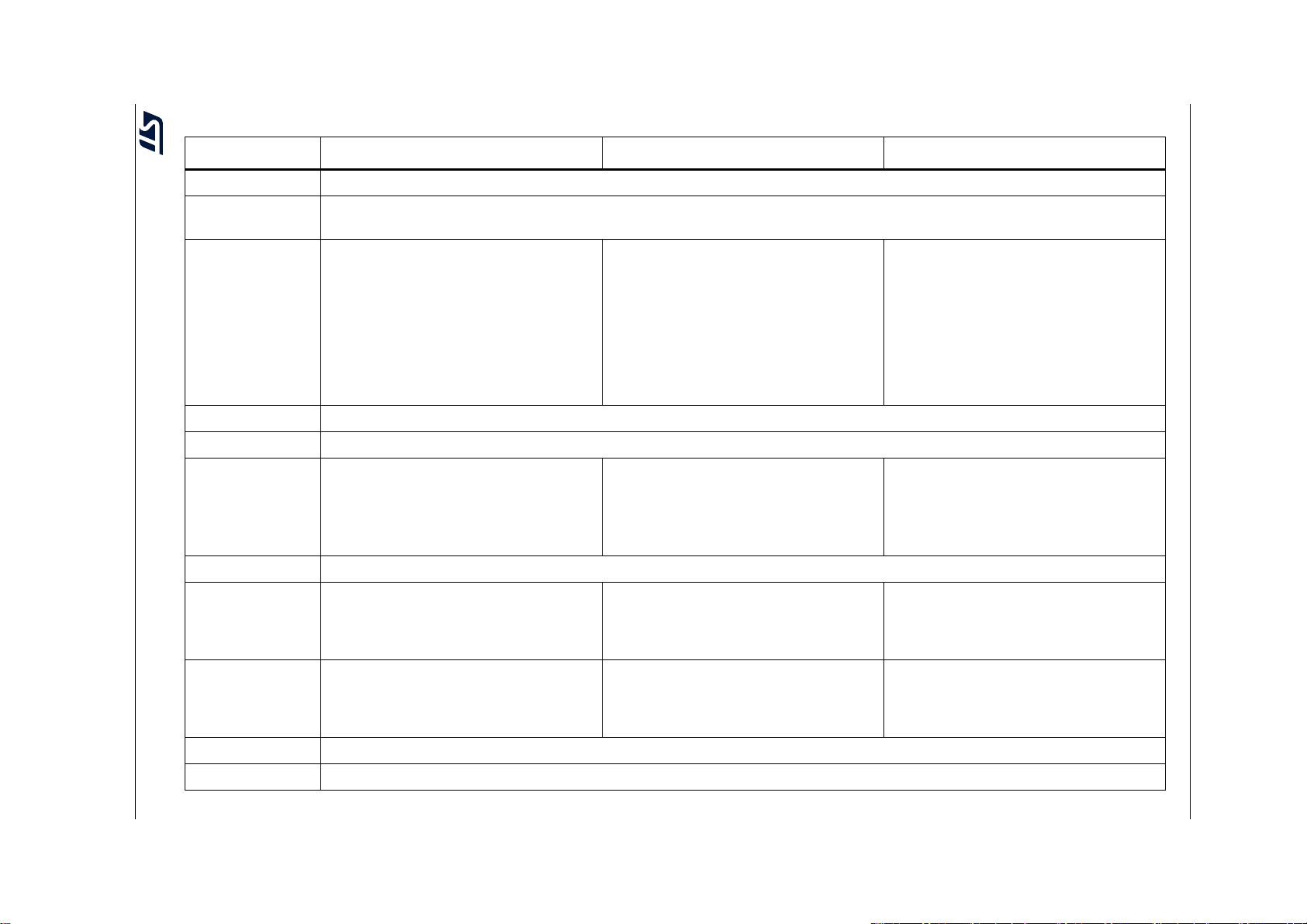
Configuration options are summarized in Table 8.
16/71 AN4435 Rev 9
Page 17
AN4435 Rev 9 17/71
Table 8. How to manage compatibility aspects and configure STL package
Feature IAR™-EWARM MDK-Arm
®
Arm
Cortex® core Include proper CPU testing start-up and runtime procedures, proper handling of core hard faults and exceptions
Frequency (MHz)
Handling SYSTCLK_AT_RUN_HSE / SYSTCLK_AT_RUN_HSI / HSE_VALUE / HSE_CLOCK_APPLIED / LSI_Freq parameters in
stm32xx_STLparam.h
Handling ROM_START / ROM_END in
stm32xx_STLparam.h
Setup LR_IROM1 load region in
Flash memory
density (KB)
Handling Checksum option in Project linker
option menu ROM_region in project icf. file
project sct file.
Define Check_Sum pattern placement
either in startup_stm32yyyyxxKEIL.s or in
project.sct file.
Implement proper post-built script files for
the automatic CRC check sum calculation.
ECC on Flash Implement handling ECC event by interrupt or by pulling
CRC configurable Handling CRC_UNIT_CONFIGURABLE parameter in stm32xx_STLparam.h
®
Handling ROM_START / ROM_END in
stm32xx_STLparam.h
Define Flash memory region in project ld
file. Implement proper post-built script files
for the automatic CRC check sum
calculation
AN4435 Main differences between STL packages from product point of view
GCC
Setup RAM_BUF, RAM_PNT, CLASSB,
CLASB_INV RW_IRAM1 in project sct file
Handling RAM_START, RAM_END,
CLASS_B_START, CLASS_B_END
parameters in stm32xx_STLparam.h
RAM density (KB)
Setup RUN_TIME_RAM_BUF_region,
RUN_TIME_RAM_PNT_region,
CLASS_B_RAM_region,
CLASS_B_RAM_REV_region, RAM_region
in project icf. file
RAM parity Handling RAM parity event by interrupt or by pulling
RAM scrambling
(1)
March-X flow during
transparent
RAM test
Define ARTISAN=1 in Project Assembler /
Preprocessor option menu when scrambling
is applied
Define USE_MARCHX_TEST=1 in Project
Assembler / Preprocessor option menu
when the flow is applied
Define ARTISAN=1 in Option for Target /
Asm / Conditional assembly control symbols
menu when scrambling is applied
Define USE_MARCHX_TEST=1 in Option
for Target / Asm / Conditional assembly
control symbols menu when the flow is
applied
ECC on E2PROM Implement handling ECC event by interrupt or by pulling
IWDG option Handling IWDG_FEATURES_BY_WINDOW_OPTION parameter in stm32xx_STLparam.h
Define CLASSBRAM and RAM regions in
project ld file.
Handling RAM_START, RAM_END,
CLASS_B_START, CLASS_B_END
parameters in stm32xx_STLparam.h.
Define ARTISAN=1 in Properties for
Assembly / Tool Settings / MCU GCC
Assembler / General / Assembler Flags
when scrambling is applied.
Define USE_MARCHX_TEST=1 in
Properties for Assembly / Tool Settings /
MCU GCC Assembler / General /
Assembler Flags when the flow is applied.
Page 18
18/71 AN4435 Rev 9
Feature IAR™-EWARM MDK-Arm
Table 8. How to manage compatibility aspects and configure STL package (continued)
®
GCC
Clock cross
reference
Setup proper timer system for cross reference measurement and handling its events
measurement
Define SUPERSET_DUAL_CORE, DUAL_CORE_MASTER, DUAL_CORE_SLAVE to include associated control of dual core
Dual core specific
setting
synchronization.
Define SW_CRC_32 flag to select 32-bit software CRC calculation.
Adapt optionally MAX_NUMBER_OF_MISSED_SLAVE_CORE_CYCLES and HSEM IDs HSEM_ID_CLASSB_SLAVE_SELFTEST,
HSEM_ID_CLASSB_SLAVE_CYCLE and HSEM_ID_CLASSB_MASTER_SELFTEST.
Handling STL_VERBOSE_POR, STL_VERBOSE, STL_EVAL_MODE, STL_EVAL_MODE_SLAVE, STL_EVAL_LCD,
NO_RESET_AT_FAIL_MODE, DEBUG_CRC_CALCULATION, STL_USER_AUX_MODE, USE_WINDOW_WDOG,
Debugging option
(2)
USE_INDEPENDENT_WDOG, HSE_CLOCK_APPLIED, IGNORE_COMPLEMENTARY_CORE_STATUS parameters in
stm32xx_STLparam.h
1. Tool specific procedures (source code written in assembler).
2. Evaluation board specific and STL optional handling when debugging the FW (not part of the safety code, but used as an application integrating example). For additional
details follow associated comments in the stm32xx_STLparam.h file and in Section 5.4.3.
Main differences between STL packages from product point of view AN4435
Page 19
AN4435 Main differences between STL packages from product point of view
3.8 Firmware integration
Self test procedures and methods targeting Class B requirements are provided in the project
examples showing how to integrate correctly the firmware into a real application. Every
integration example uses dedicated products and evaluation HW boards. Apart from
common drivers and procedures, it also includes product, evaluation board or compiler
specific drivers not directly related to the safety task but rather included for demonstration or
debugging purposes (details are given in
Section 2: Package variation overview).
User has to take care of dedicated linker file content and project specific settings to
integrate the STL stack and all the methods used properly into the target application.
Pay attention to the definition of memory areas under test (RAM and Flash), to the allocation
of memory space for Class B variables and stack, and to the definition of the control flow.
Additional details are provided in the following sections of this document.
3.9 HAL driver interface
When all the debug and verbose support (UART channel, LCD display, LEDs or auxiliary
GPIO signals) is removed from the packages, the interface between HAL layer and STL
procedures is reduced to drivers needed to control specific peripherals used during start-up
and run time self tests. An overview is given in
Table 9. Overview of HAL drivers used by STL stack procedures
Tabl e 9.
HW component HAL drivers used STL files
Core SysTick timer HAL_SYSTICK_Config stm32xx_STLmain.c
NVIC
Clock system
Timers
CRC unit
HAL_NVIC_SetPriority
HAL_NVIC_EnableIRQ
HAL_NVIC_SystemReset
HAL_RCC_OscConfig
HAL_RCC_ClockConfig
HAL_RCC_EnableCSS
HAL_TIM_IC_Init
HAL_TIMEx_RemapConfig
HAL_TIM_IC_ConfigChannel
HAL_TIM_IC_Start_IT
__TIMx_CLK_ENABLE
HAL_CRC_Init
HAL_CRC_DeInit
HAL_CRC_Accumulate
HAL_CRC_Calculate
__HAL_CRC_DR_RESET
__CRC_CLK_ENABLE()
stm32xx_STLstartup.c
stm32xx_it.c
stm32xx_STLstartup.c
stm32xx_STLclockstart.c
stm32xx_STLclockrun.c
stm32xx_it.c
stm32xx_STLstartup.c
stm32xx_STLcrc32Run.c
AN4435 Rev 9 19/71
70
Page 20
Main differences between STL packages from product point of view AN4435
Table 9. Overview of HAL drivers used by STL stack procedures (continued)
HW component HAL drivers used STL files
HAL_IWDG_Init
HAL_WWDG_Init
HAL_IWDG_Start
IWDG and WWDG
HAL layer
HAL_WWDG_Start
HAL_IWDG_Refresh
HAL_WWDG_Refresh
__HAL_RCC_CLEAR_FLAG
__HAL_RCC_GET_FLAG
__WWDG_CLK_ENABLE()
HAL_Init
HAL_IncTick
HAL_GetTick
stm32xx_STLstartup.c
stm32xx_STLmain.c
stm32xx_STLstartup.c
stm32xx_STLmain.c
stm32xx_it.c
Note: Be careful when using a HAL version newer than that used for the STL certification, check
changes summarized in release notes. For more information refer to
Section 3.10.
3.10 Incompatibility with previous versions of the STL
User has to be careful when a different version of compiler or HAL is applied to implement
the STL testing procedures (see
Tabl e 1).
The push towards optimization of code size and speed makes the providers of compilers to
apply specific and more sophisticated methods of making code structure, even if users do
not need these optimizations, which make the code too compressed and difficult to be
analyzed or debugged.
One of the requirements is that each subroutine keeps the content of core registers R4 to
R11 (this was not required with lower levels of optimization, and so not kept in Revision
2.2.0, corrected for more recent versions, for product specific startup tests written in
assembly). In case of CPU test the modification is easy (it is only needed to push these
registers into stack at the beginning of the procedure and restore them back before return,
either by push and pop or stmdb and ldmia instructions:
STL_StartUpCPUTest:
; Save preserved registers values into stack
STMDB SP!, {R4, R5, R6, R7, R8, R9, R10, R11}
...
; Restore preserved registers values from stack
LDMIA SP!, {R4, R5, R6, R7, R8, R9, R10, R11}
BX LR ; return to the caller
Another issue related to the compiler optimization can be an unexpected replacement of the
control flow (based on step by step filling of the specific dedicated flow control registers
between the test caller and caller procedures) by a single last time setup of these registers
by final expected values (precomputed by the compiler during compilation) just prior the
program starts to check their content. This is why it is strongly suggested to set the lowest
possible optimization for the stm32xx_STLstartup.c file compilation configuration.
20/71 AN4435 Rev 9
Page 21

AN4435 Main differences between STL packages from product point of view
One of the crucial definition of commonly used error status enumerator is changed in HAL
library so that the assembler-written STL code, which relies on the original definition, has to
be either adapted or declared independently from the common operator recognized at
C-level. To make the FW independent on HAL definition of this enumerator user can define
specific enumerator dedicated to the test and modify the declaration of the related test
function accordingly. For example, to correctly evaluate result of RAM startup test, the
stm32xx_STLRam.h file has to be modified in following way:
typedef enum
{
SRAMTEST_SUCCESS = 1,
SRAMTEST_ERROR = !SRAMTEST_SUCCESS
} SRAMErrorStatus;
and
SRAMErrorStatus STL_FullRamMarchC(uint32_t *beg, uint32_t *end, uint32_t
pat, uint32_t *bckup);
while comparison of result when startup test is called in the stm32xx_STLstartup.c file has
to be modified in following way:
...
if (STL_FullRamMarchC(RAM_START, RAM_END, BCKGRND, RAM_BCKUP) !=
SRAMTEST_SUCCESS)
{
...
The upper workaround is applied only for RAM startup test since revision 2.3.0 of the STL,
while a unique STL specific enumerator STLErrorStatus is defined for all the associated
testing APIs from revision 2.4.0.
There is an additional back-up pointer added as a next input parameter since revision 2.3.0
when calling the startup SRAM test procedure, not used in previous versions of the library.
This is an optional solution to solve the problem seen during the CPU startup test, and to
save preserved registers. The RAM_BCKUP pointer held at R3 during the call has to point
at the beginning of some volatile memory area with 16 bytes capacity to save registers R4R7 used and modified by the self test. The situation here is a bit more complicated as the
test can destroy the stack content if the stack area is under test. User then has to save the
preserved registers to another SRAM or into a part of memory excluded from the test. The
test has to start and finish by storing and restoring the registers from the address provided
by R3:
STL_FullRamMarchC:
STMIA R3!,{R4-R7} ; Save content of preserved registers R4-R7
...
LDMDB R3!,{R4-R7} ; Restore R4-R7 content
BX LR ; return to the caller
The R3 content cannot be modified by the procedure. Its original implementation has to be
replaced using R7. If there is no area available for such a backup, user can adopt another
optional solution and save the R4-R7 registers one by one in some RW peripheral registers
not used at startup.
There can be problems with modified HEX file load at debugger entry with latest versions of
the MDK-Arm
®
because it no longer performs load of the user defined initialization file as
the last action of the debugger entry, hence the Flash memory remains programmed by its
AN4435 Rev 9 21/71
70
Page 22

Main differences between STL packages from product point of view AN4435
default content at the end. Only the modified HEX file keeps a valid CRC image of the code,
hence the execution of the default memory integrity check fails. As a workaround, copy
correct CRC pattern from the HEX file to the CHEKSUM segment definition defined at the
end of the startup_stm32xxxx.s modified assembly file (KEIL compiler case), or directly at
segment placing the check sum result at linker script file (GCC compiler), and recompile the
project with the correct CRC pattern copy after modifications of the source files. Another
debugging option is to define DEBUG_CRC_CALCULATION conditional flag during
compilation, when the CRC result calculated during the start up test is applied for the run
time test, whatever the CHECKSUM segment content.
With the latest versions of the IAR compiler user can face problem with segment placement
in the RAM. This is due to overlay of the common read/write section and class B related
sections in the region defined by the provided icf linker file. User has to separate the content
of these sections by changing the definition of the common section start to put it out of the
class B sections range:
...
define symbol __ICFEDIT_region_CLASSB_end__ = 0x2000007F;
define symbol __ICFEDIT_region_user_RAM_start__ = 0x20000080;
define region RAM_region = mem:[from __ICFEDIT_region_user_RAM_start__
to __ICFEDIT_region_RAM_end__];
place in RAM_region { readwrite, rw section .noinit };
3.11 Dual core support
The main difference between STL library versions 2.x.x and 3.0.0 is the added support of
communication and synchronization between testing processes running in parallel on two
embedded cores, to provide the firmware solution for dual core products. Both cores
perform standard standalone single core testing procedures adopted by versions 2.x.x in
parallel, with exceptions described in this section.
The core that plays the role of master overtakes the configuration control and testing of the
common clock system during startup and run time. The slave core does not perform any
clock control.
Each core uses and tests its own watchdog system independently. No common reset is
adopted. User can enable it by hardware configuration, or enable specific interrupts for
reciprocal monitoring of the window watchdog activity.
To prevent any competition of the embedded hardware CRC unit occupancy, the slave core
does not use this unit for its non-volatile memory verification but applies software
calculation.
Two newly added files stm32xx_STLcrcSW.c and stm32xx_STLcrcSWRun.c collect the
dedicated lookup tables loop cycles with all the associated data sets and step by step
handling of the memory test at run time per blocks. The files include conditionally compiled
parts handled by definition of SW_CRC_32 flag (defined at common parametrization
stm32xx_STLparam.h header file) selecting either 16-bit or 32-bit CRC calculations upon
0x11021 and 0x104C11DB7 polynomials recognized by IEEE standard. This is a flexible tool
for the end user to select procedures sufficient to ensure the required reliability with respect
to performance and mainly memory capacity available in the application (to accommodate
look up table data).
22/71 AN4435 Rev 9
Page 23

AN4435 Main differences between STL packages from product point of view
At startup, a single loop testing cycle over the memory area is called, by direct call of
STL_crc16() or STL_crc32() procedures. Such a tested area has to be then aligned with,
respectively, 2- or 4-byte multiples.
At run time, sequence of partial tests is called under the same principle as when HW CRC
unit is applied to separate the memory test into small blocks (block size is set by
FLASH_BLOCK parameter to 32 bytes by default). This sequence is handled by repeated
calling of STL_CrcSWRun() procedure which returns ClassBTestStatus enumerator values
to identify the test phase and result. Each new test sequence has to be initialized by
STL_FlashCrcSWInit() procedure pre-call. The tested area has to be aligned with the block
size setting. The number of the tested blocks is verified by control flow (see definition of the
FULL_FLASH_CHECKED). Both values of partial checksum result and pointer to the Flash
memory is carried as complementary Class B variable type pair and checked for
consistency at each step of the sequence.
The applied SW methods use different CRC algorithms, which requires wider setting
modifications of the tool providing pattern matching with the calculation result (e.g. IAR
IDE). The CRC-32 algorithm requires byte reversed input and reversed output of the bit flow,
differently from the CRC-16 one. To receive IEEE compliant result, the output has to be
additionally reversed by XOR with “all 1” pattern (this is not a case of comparison with
pattern provided by IAR).
User must take care about linker file setting, too, to assure adequate placement of the check
sum out of the tested area at required format when switching between 32-bit and 16-bit
software CRC calculation due to casting of the calculation result.
When compiler does not support the checksum (like Arm-KEIL or GCC), the situation is
much more complex: the user must handle correct setting of a post-built calculation
provided by external tool additionally and insert correct pattern into the project (modify
CHECKSUM segment defined at the end of the code area). To assure that, specific batch
procedures are prepared based on SREC freeware tool, which performs modification of the
HEX file provided by IDE.
For debugging purposes is crucial to keep load of the original code image and symbols, not
available for modified HEX file. Older versions of the applied IDEs allow to load the modified
HEX file as a last step of the debug mode entry. Unfortunately, it is no more possible with
the latest versions of the IDEs when original HEX is loaded exclusively at the end. This
overwrites the modification of the original file, making debugging of the CRC calculation
result quite complicated and time consuming (the only way is to modify the CRC value by
editing the sources after whatever change to match original and modify HEX files).
For an initial debugging user can avoid this external process and implement
DEBUG_CRC_CALCULATION feature.
The two cores communicate via specific embedded hardware semaphore system unit
(HSEM) to cross check each other activity and testing status. Both cores monitor HSEM
events by interrupts and process occupancy checks of dedicated channels permanently to
see the STL correct ongoing status. Master core monitors periodicity of the slave STL test
cycles completed under timeout evaluation additionally on a separate channel.
The STL occupancy of HSEM channels and their distribution between master (Cortex® M7)
and slave (Cortex
product is shown in
®
M4) cores for the STL 3.0.0 integration example on the STM32H747
Figure 1.
AN4435 Rev 9 23/71
70
Page 24

Main differences between STL packages from product point of view AN4435
MS54334V1
HSEM_ID_CLASSB_
SLAVE_SELFTEST (9)
HSEM_ID_CLASSB_
SLAVE_CYCLE (10)
HSEM_ID_CLASSB_
MASTER_SELFTEST (11)
Master and slave enter FailSafe when receiving
complementary HSEM STL activity ID release annotation
Master takes its HSEM ID to
indicate start of STL activity
Slave takes associated HSEM IDs to
indicate start of the STL activity
Each release of this HSEM cycle ID by slave raises master
interrupt and resets the slave activity timeout handled by master
Master and slave check if reciprocal HSEM activity IDs are
overtaken once their initial startup test cycle is complete
Master uses its run time test cycle complete period
to increase the slave HSEM cycle ID activity timeout
Master enters FailSafe when slave HSEM
cycle ID activity timeout overflows
Figure 1. HSEM IDs distribution and control
The slave uses channel IDs 9 and 10, while the master uses only channel ID 11. Channel
IDs 9 and 11 perform global STL ongoing status of the cores, channel ID 10 informs master
whenever slave completes the STL testing cycle successfully. Both cores initially verify if the
complementary core overtakes its channel(s) during startup and make itself sensitive for
interrupt whenever each of them is released. When one of the cores faces interrupt from
complementary channel indicating correct STL activity status release, it puts itself to fail safe
state by default. When master faces interrupt from the slave channel indicating completed
STL test cycle, it sets timeout (clears counter counting completion of master testing cycles
which determines the period of this counter increments). User can set maximum number of
master complete cycles as a limit to detect single complete event from slave by constant
MAX_NUMBER_OF_MISSED_SLAVE_CORE_CYCLES. When master achieves this limit
by the counter, it evaluates problem at slave side and puts itself in safe state by default.
The code associated with dual core handling is included with conditional compilation flags
into the 2.4.0 version source files, hence the 3.0.0 code coincides with the 2.4.0 code if the
dual core support is not included. User can monitor all this added or modified code through
conditional code blocks under SUPERSET_DUAL_CORE user define control in the library
source files. The code is then divided based on DUAL_CORE_SLAVE and
DUAL_CORE_MASTER user defines. To cover single core products, the dedicated source
files STLstartup and STLmain are not kept in the STL but new source files
STLstartup_DualCore and STLmain_DualCore have replaced them. User can switch back
to the original source content by keeping conditional the flag SUPERSET_DUAL_CORE not
defined.
Standard STL diagnostic verbose mode performed on dedicated UART interface is
supposed to be implemented by main core only at time of debugging. BSP LED signals can
be provided from both cores optionally to indicate system status. The master core uses
standard set of LEDs indicating RAM and FLASH testing cycles and safe error status, the
slave core controls a single additional LED toggling with Flash testing cycles at run time
only.
24/71 AN4435 Rev 9
Page 25

AN4435 Main differences between STL packages from product point of view
For debugging purpose, user can make independent the testing processes running on both
cores by uncommenting define IGNORE_COMPLEMENTARY_CORE_STATUS. In this
case, the associated cross monitoring stays active and it is evaluated but not taken into
account and each core continues the normal STL execution even if problems are reported
by the other core.
AN4435 Rev 9 25/71
70
Page 26

Compliance with IEC, UL and CSA standards AN4435
4 Compliance with IEC, UL and CSA standards
IEC (International Electrotechnical Commission) is a not-for-profit and non-governmental
world wide recognized authority preparing and publishing international standards for a vast
range of electrical, electronic and related technologies. IEC standards are focused mainly
on safety and performance, the environment, electrical energy efficiency and its renewable
capabilities. The IEC cooperates closely with the ISO (International Organization for
Standardization) and the ITU (International Telecommunication Union). Their standards
define not only the recommendations for hardware but as well for software solutions divided
into a number of safety classes in dependency of the purpose of the application.
Other world wide recognized bodies in the field of electronic standards are TUV or VDE in
Germany, IET in the United Kingdom and the IEEE, UL or CSA in the United States and
Canada. Beyond providing expertise during standard development process, they act as
testing, inspection, consultancy, auditing, education and certification bodies. Most of them
target global market access but are primarily recognized and registered as a local national
certification bodies (NCB) or national recognized testing labs (NRTL). The main purpose of
these institutions is to offer standards compliance and quality testing services to
manufacturers of electrical appliances.
Due to globalization process, most of manufacturers push for harmonization of national
standards. This is contrary to the efforts of many governments, still protecting smaller local
producers by building administrative barriers to prevent easy local market access from
abroad. As a matter of fact, most of the standards are well harmonized, with negligible
differences. This makes the certification process easier, and any cooperation with locally
recognized bodies is fruitful.
The pivotal IEC standards are IEC 60730-1 and IEC 60335-1, well harmonized with UL/CSA
60730-1 and UL/CSA 60335-1 starting from their 4th edition (previous UL/CSA editions use
references to UL1998 norm in addition). They cover safety and security of household
electronic appliances for domestic and similar environment.
The standards applied during inspection are always listed in the final report provided by the
certification authority. These standards undergo a continuous development and upgrade
process. When a new edition appears, not necessarily the FW certified according to a
previous version does not meet the new requirements, and not necessarily the applied
testing methods become wrong. Often new editions just collect sets of already existing
updates, and the relevant part of the standard is not (or slightly) impacted.
Appliances incorporating electronic circuits are subject to component failure tests. The basic
principle here is that the appliance must remain safe in case of any component failure. The
microcontroller is an electronic component as any other one from this point of view. If safety
relies on an electronic component, it must remain safe after two consecutive faults. This
means that the appliance must stay safe with one hardware failure and the microcontroller
not operating (under reset or not operating properly).
The conditions required are defined in detail in Annexes Q and R of the IEC 60335-1 norm
and Annex H of the IEC 60730-1 norm.
Three classes are defined by the 60730-1 standard:
Class A: Safety does not rely on SW
Class B: SW prevents unsafe operation
Class C: SW is intended to prevent special hazards.
26/71 AN4435 Rev 9
Page 27

AN4435 Compliance with IEC, UL and CSA standards
For programmable electronic component applying a safety protection function, the 60335-1
standard requires incorporation of software measures to control fault /error conditions
specified in tables R.1 and R.2, based on Table H.11.12.7 of the 60730-1 standard:
Table R.1 summarizes general conditions comparable with requirements given for
Class B level in Table H.11.12.7.
Table R.2 summarizes specific conditions comparable with requirements for Class C
level of the 60730-1 standard, for particular constructions to address specific hazards.
Similarly, if software is used for functional purposes only, the R.1 and R.2 requirements are
not applicable.
The scope of this Application note and associated STL package is Class B specification in
the sense of 60730-1 standard and of the respective conditions, summarized in Table R.1 of
the 60335-1 standard.
If safety depends on Class B level software, the code must prevent hazards if another fault
occurs in the appliance. The self test software is taken into account after a failure. An
accidental software fault occurring during a safety critical routine does not necessarily result
into an hazard thanks to another applied redundant software procedure or hardware
protection function. This is not a case of much more severe Class C level, where fault at a
safety critical software results in a hazard due to lack of next protection mechanisms.
Appliances complying with Class C specification in the sense of the 60730-1 standard and
of the respective conditions summarized in Table R.2 of the 60335-1 standard are outside
the scope of this document as they need more robust testing and usually lead to some
specific HW redundancy solutions like dual microcontroller operation. In this case, user
must use product dedicated safety manuals and apply the methods described there.
Class B compliance aspects for microcontrollers are related both to hardware and software.
The compliant parts can be divided into two groups, i.e. micro specific and application
specific items, as exemplified in
Table 10.
While application specific parts rely on customer application structure and must be defined
and developed by user (communication, IO control, interrupts, analog inputs and outputs)
micro specific parts are related purely to the micro structure and can be generic (core self
diagnostic, volatile and non-volatile memories integrity checking, clock system tests). This
group of micro specific tests is the focus of the ST solution, based on powerful hardware
features of STM32 microcontrollers, like double independent watchdogs, CRC units or
system clock monitoring.
Microcontroller specific
Table 10. MCU parts that must be tested under Class B compliance
Group Component to be tested according to the standard
CPU registers
CPU program counter
System clock
Invariable and variable memories
Internal addressing (and External if any)
Internal data path
AN4435 Rev 9 27/71
70
Page 28

Compliance with IEC, UL and CSA standards AN4435
Table 10. MCU parts that must be tested under Class B compliance (continued)
Group Component to be tested according to the standard
Interrupt handling
External communication
Application specific
Timing
I/O periphery
Analog A/D and D/A
Analog multiplexer
4.1 Generic tests included in STL firmware package
The certified STM32 STL firmware package is composed by the following micro specific
software modules:
CPU registers test
System clock monitoring
RAM functional check
Flash CRC integrity check
Watchdog self test
Stack overflow monitoring.
Note: The last two items from the upper list are not explicitly requested by the norm, but they
improve overall fault coverage and partially cover some specific required testing (e.g
internal addressing, data path, timing).
An overview of the methods used for the MCU-specific tests (described in deeper detail in
the following sections) is given in
Tab l e 11 .
User can include a part or all of the certified SW modules into its project. If they are not
changed and are integrated according with these guidelines the time and costs needed to
get a certified end-application is be significantly reduced.
When tests are removed the user must consider side effects, as not applied tests can play a
role in the testing of other components as well.
28/71 AN4435 Rev 9
Page 29

AN4435 Compliance with IEC, UL and CSA standards
Table 11. Methods used in micro specific tests of associated ST package
References to Annex R of
Component
of Table R.1
to be verified
CPU registers
Program
counter
Addressing
and data path
Clock
Invariable
memory
Var iable
memory
Method used
Functional test of all registers and flags including R13 (stack
pointer), R14 (link register) and PSP (Process stack pointer) is done
at start-up. At run test R13, R14, PSP and flags are not tested.
Stack pointer is tested for overflow, (underflow is checked by nondirect methods) link register is tested by PC monitoring. If any error
is found, the software jumps directly to the Fail Safe routine.
Two different watchdogs running with two independent clock
sources can reset the device when the program counter is lost or
hanged-up. The Window watchdog, driven by the main oscillator,
performs time slot monitoring and Independent one, driven by low
speed internal RC oscillator, is impossible to disable once enabled.
Program control flow is monitored using a specific software method
additionally.
Not all the ST products satisfy the recognized methods for this test.
This lack can be compensated by implementing a wider set of
indirect methods like RAM functional and Flash memory integrity
test, program timing and flow control, class B variables integrity and
stack boundaries checks supported by other HW methods like
proper handling of CPU exceptions.
A cross check measurement between two independent sources of
frequency is used while measured frequency clocks the timer and
second one gates the timer clock input. As an example, wrong
frequency of external crystal (harmonic/sub harmonic) can be
detected using time base of internal low speed RC oscillator for
gating the timer.
32-bit CRC check sum test of full memory is done at start-up and
partial memory test is repeated at run time (block by block). Fast
built-in hardware 32-bit CRC calculation unit is used.
March C- full memory test is done at start-up and partial memory
test is repeated at run time (block by block over the Class B storage
area exclusively). Scrambled order of physical addresses in RAM is
respected in the tests for optimal coverage of coupling faults. Faster
March X can be optionally used for testing at run time. Word
protection with double redundancy (inverse values stored in non
adjacent memory space) is used for safety critical Class B variables,
Class A variables space, stack and not used space are not tested
during run time.
IEC 60335-1 and Annex H
of IEC 60730-1
Component(s) Definition
H.2.16.5
1.1
1.3
4.3, 5.1 and 5.2
3
4.1
4.2
H.2.16.6
H.2.19.6
H.2.18.10.2
H.2.18.10.4
H.2.19.18.1
H.2.19.18.2
or indirect
methods
H.2.18.10.1
H.2.18.10.4
H.2.19.4.1
H.2.19.8.1
H.2.19.6.2
H2.19.8.2
The applied tests are primarily dedicated to detect permanent faults (to cover faults under
so called d.c. fault model). Detection of transient faults by any software testing is always
limited, because of the relatively long repetition period of testing (in comparison with any
HW methods with permanent checking capability), and can be covered partially with indirect
routes.
Note: In case of minor changes to the modules, the user has to keep track of all of them, placing
clear explanation commentaries in the source files and informing the certification authorities
of the differences vs. the certified routines.
AN4435 Rev 9 29/71
70
Page 30

Compliance with IEC, UL and CSA standards AN4435
4.2 Application specific tests not included in ST firmware self test library
User must focus on all the remaining required tests covering application specific MCU parts
not included in the ST firmware library:
test of analog parts (ADC / DAC, multiplexer)
test of digital I/O
external Addressing
external communication
timing and interrupts.
A valid solution for these components is strongly dependent on application and device
peripheral capability. The recommendation is to respect the suggested testing principles
from the very early stages of application design.
Very often this method leads to redundancy at both HW and SW levels.
HW methods must be based on:
multiplication of inputs and/or outputs
reference point measurement
loop-back read control at analog or digital outputs like DAC, PWM, GPIO
configuration protection.
SW methods must be based on:
repetition in time, multiple acquisitions, multiple checks, decisions or calculations made
at different times or performed by different methods
data redundancy (data copies, parity check, error correction/detection codes,
checksum, protocoling)
plausibility check (valid range, valid combination, expected change or trend)
periodicity and occurrence checks (flow and occurrence in time controls)
periodic checks of correct configuration (e.g. read back the configuration registers).
4.2.1 Analog signals
Measured values must be checked for plausibility and verified by measurements performed
by other redundant channels, while free channels can be used for reading some reference
voltages in conjunction with testing of analog multiplexers used in the application. The
internal reference voltage must also be checked.
Some STM32 devices feature two (or even three) independent ADC blocks. It makes sense
to perform conversions on the same channel using two different ADC blocks for security
reasons. Multiple acquisition at one channel or compare redundant channels followed by
average operation can be applied.
Here are some tips for testing the functionality of analog parts at STM32 microcontrollers.
30/71 AN4435 Rev 9
Page 31

AN4435 Compliance with IEC, UL and CSA standards
ADC input pin disconnection
Can be tested by applying additional signal source injection on the tested pin
Some STM32 devices feature internal pull-down or pull-up resistor activation on the
analog input or free pin with DAC functionality (or a digital GPIO output) can be used
for the injection.
Some STM32 devices feature routing interface. It can be used for internal connection
between pins to make testing loop-back, additional signal injection or duplicate
measurement at some other independent channel.
Note: User has to prevent a critical injection into the analog pin. This can happen when digital and
analog signals are combined while different power levels are applied to analog and digital
parts (V
DD
> V
DDA
).
Internal reference voltage and temperature sensor (VBAT for some devices)
Ratio between these signals can be verified within the allowed ranges
Additional testing can be performed where the V
voltage is known.
DD
ADC clock
Measurement of the ADC conversion time (by timers) can be used to test the
independent ADC clock functionality.
DAC output functionality
Free ADC channels can be used to check if the DAC output channel is working
correctly.
The Routing interface can be used for connection between the ADC input channel and
the DAC output channel.
Comparator functionality
Comparison between known voltage and DAC output or internal reference voltage can
be used for testing comparator output on another comparator input.
Analog signal disconnection can be tested by pull-down or pull-up activation on tested
pin and comparing this signal with DAC voltage as reference on another comparator
input.
Operational amplifier
Functionality can be tested forcing (or measuring) a known analog signal to the
operational amplifier (OPAMP) input pin, and internally measuring the output voltage
with the ADC. The input signal to OPAMP can be also measured by ADC (on another
channel).
4.2.2 Digital I/Os
Class B tests must detect any malfunction on digital I/Os, too. It could be covered by
plausibility checks together with some other application parts (e.g. change of an analog
signal from temperature sensor must be checked when heating/cooling digital control is
switched on/off). Selected port bits can be locked by applying the correct lock sequence to
the lock bit in the GPIOx_LCKR register to prevent unexpected changes to the port
configuration. Reconfiguration is only possible at the next reset sequence in this case. In
AN4435 Rev 9 31/71
70
Page 32

Compliance with IEC, UL and CSA standards AN4435
addition, the bit banding feature can be used for atomic manipulation of the SRAM and
peripheral registers.
4.2.3 Interrupts
Occurrence in time and periodicity of events must be checked. Different methods can be
used; one of them uses set of incremental counters where every interrupt event increments
a specific counter. The values in the counters are then cross-checked periodically with other
independent time bases. The number of events occurred within the last period depends
upon the application requirements.
The configuration lock feature can be used to secure the timer register settings with three
levels controlled by the TIMx_BDTR register. Unused interrupt vectors must be diverted into
common error handler. Polling is preferable for non safety relevant tasks if possible to
simplify application interrupt scheme.
4.2.4 Communication
Data exchange during communication sessions must be checked while including a
redundant information into the data packets. Parity, sync signals, CRC check sums, block
repetition or protocol numbering can be used for this purpose. Robust application software
protocol stacks like TCP/IP give higher level of protection, if necessary. Periodicity and
occurrence in time of the communication events together with protocol error signals has to
be checked permanently.
User can find more information and methods in product dedicated safety manuals.
4.3 Safety life cycle
Development and maintenance of FW are provided with respect to requirements of
UL/IEC
H.11.12.3. All the associated processes follow the ST internal policy to ensure they have the
required level of quality.
Application of these internal rules and the compliance with the recognized standards are the
target of regular inspections and audits carried out by recognized external inspection
bodies.
Specification of safety requirements
The main target was pointed by internal planning to provide set of generic modules
independent on user application to be easily integrated into user firmware targeting
compliance with UL/IEC 60730-1 and UL/IEC 60335-1 standards. Used solutions and
methods reviewed by certification authority speed up the user development and certification
processes.
Architecture planning
The STL packet structure is the result of a long experience with repeatedly certified FW,
where modules were integrated into ST standard peripheral libraries dedicated to different
products in the past. Main goal of the new FW has been to remove any HW dependence on
different products and integration of safety dependent parts into a single common stack of
self tests based on new unique hardware abstraction interface (HAL) developed for the
whole STM32 family.
60730-1 concerning prevention of systematic errors focused mainly in Section
32/71 AN4435 Rev 9
Page 33

AN4435 Compliance with IEC, UL and CSA standards
Such common architecture is considerably safer from a systematic point of view, involves
easier maintenance and integration of the solution when migrating either between existing
or into new products. The same structures are applied by many customers in many different
configurations, so their feedback is absolutely significant and helps to efficiently address
weaknesses, if any.
Planning the modules
The testing methods of modules comes from proved solutions used at the original FW.
Some methods were optimized to speed up the test period and so minimize limitation of the
process safety time at the final application applying these self testing methods, provided
mostly by software.
Coding
Coding is based on principles defined by internal ST policy, respecting widely recognized
international standards of coding, proven verification tools and compilers.
Emphasis is put on performing very simple and transparent thread structure of code, calling
step by step the defined set of testing functions while using simplified and clear inputs and
outputs.
The process flow is secured by specific control mechanism and synchronized with system
tick interrupts providing specific particular background transparent testing. Hardware
watchdogs service is provided exclusively once the full set of partial checking procedures is
successfully completed.
Testing modules
Modules have been tested for functionality on different products, with different development
tools. Details can be found in the following sections and in the specific test documentation
dedicated to certification authorities (test report).
Modules integration testing
Modules integration has been tested in several examples dedicated to different products
using different development tools, focusing on proper timing measurements, code control
flow, stack usage and other methods. Again, details can be found in the following sections
and in the test documentation.
Maintenance
For the FW maintenance ST uses feedback from customers (including preliminary beta
testers) processed according to standard internal processes. New upgrades are published
at regular intervals or when some significant bugs are identified. All the versions are
published with proper documentation describing the solution and its integration aspects.
Differences between upgrades, applied modifications and known limitations are described in
associated release notes included in the package.
Specific tools are used to support proper SW revision numbering, source files and the
associated documentation archiving.
All the FW and documentation are available to ST customers directly from www.st.com, or
on request, made to local supporting centers.
AN4435 Rev 9 33/71
70
Page 34

Class B software package AN4435
5 Class B software package
This section highlights the basic common principles used in ST software solution. The
workspace organization is described together with its configuration and debugging
capabilities. The differences between the supported development environments
(IAR™-EWARM, Keil® MDK-Arm® and GCC Eclipse™ based SW4STM32 and
STM32CubeIDE) are addressed.
5.1 Common software principles used
The basic software methods and common principles used for all the tests included in the ST
solution are described in detail in this section.
5.1.1 Fail safe mode
A dedicated procedure, FailSafePOR(), is called when a fail is detected by the self test
procedures. The routine is predefined at the beginning of stm32xx_STLstartup.c file. The
goal of this procedure is to provide a unique output and allow the user to react immediately.
By default, there is no specific handling inside the procedure except for debug support and
an empty loop waiting for a watchdog reset (the reset can be prevented in debug mode). It is
fully upon user responsibility to build up a handler inside this routine and perform all the
necessary steps to bring the application in a safe state, while taking a decision on the next
cycle in dependency of the severity of the problem found.
Optionally, the user can redefine the procedure and pass a specific input parameter (a
simple constant) when calling it from different places of the program to identify the severity
of the problem and simplify the decision flow inside the procedure.
The debug or verbose mode described in Section 5.4: Package configuration and
debugging can be used to identify error occurred.
5.1.2 Safety related variables and stack boundary control
It is highly recommended to handle critical values related to system safety in a specific way.
Each class B variable is stored as a pair of two complementary values in two separate RAM
regions. Both normal and redundant complementary values are always placed into non
adjacent memory locations. A partial transparent RAM March C- or March X run time test is
continuously performed, step by step, on these RAM areas by a specific interrupt
subroutine. The buffer used for temporarily storage and back recovery of the tested area is
within the range tested permanently, too.
User has to ensure that every pair is always compared for integrity before the value is used.
Fail Safe mode has to be invoked if any pair integrity is corrupted. If the value of a variable is
changed on purpose, both storage locations need to be updated to keep the correct integrity
of the pair.
An example of RAM configuration is shown in Figure 2. User can adapt the RAM space
allocation according to the application needs and hardware capability. For better
consistency of the run time test, all the class B regions are merged together within a single
compact memory location.
34/71 AN4435 Rev 9
Page 35

AN4435 Class B software package
MS35281V4
Class B variables
(redundant complementary values)
Class B variables
(normal values)
Area under
run time
check
Gap (overlap) at the beginning
of Class B area
Gap (overlap) at the end
of Class B area
Area tested during
the first step
Area tested during
the second step
Area tested during
the last step
Area tested during
the last but one step
. . .
Overlap
Overlap
Class A variables
Unused RAM
Specific pattern to detect stack
overflow
Stack
Specific pattern to detect stack
underflow*
* Next pattern must be stored here if the stack does not start at the end of the RAM
Area under
run time
check
Area under
run time
check
RAM backup buffer
Pointer to Class B area
Figure 2. Example of RAM configuration
The user has to align the size of the tested area to multiply single transparent steps while
respecting overlay used for the first and last step of the test, including address scrambling.
That is why the user has to allocate dummy gaps at the beginning and at the end of the area
dedicated to Class B variables. Size of these gaps has to correspond to applied overlay of
the tested single block.
Backup buffer and pointer to Class B area has to be allocated out of the area dedicated to
Class B variables, at a specific location tested separately each time the overall Class B area
test cycle is completed.
AN4435 Rev 9 35/71
70
Page 36

Class B software package AN4435
Specific pattern is written at the low boundary of stack space and checked for corruption at
regular intervals to detect the stack overflow. To check its underflow, a second pattern can
be written at high boundary if the stack is not placed at top of RAM. If the stack is placed at
top of RAM an underflow event raises hardware exception event.
When more than a single stack area is used by the application, it is advisable to separate
the adjacent areas by boundary patterns to check that all the pointers operate exclusively
within their dedicated areas.
Stack and non safety RAM area are not checked by the Transparent RAM test at run time.
5.1.3 Flow control procedure
Program flow control is a method highly recommended by the standards, because is an
efficient way of ensuring that all specific parts of code are correctly executed and passed.
This method is an efficient tool to identify bus matrix issues (e.g. data transfer, addressing).
A specific software method is used for this check. Unique labels (constant numbers) are
defined for identifying all key points (blocks with component tests) in the code flow in order
to make sure that no block is skipped and that all the flow is executed as expected. The
unique labels are processed in two complementary counters complying with class B variable
criteria. The main principle is a symmetrical four steps change of the counter pair content
(adding or subtracting the unique label values) each time any significant testing block is
processed. Two of these check steps are placed outside the called block at caller (main
flow) level. This ensures that the block is correctly called from main flow level (processed
just before calling and just after return from the called procedure). The next two steps are
performed inside the called procedure to ensure that the block is correctly completed
(processed just after enter and just before return from the procedure).
An example is given in Figure 3, where a routine performing a component test is called in
the controlled flow sequence and the four-step checking service is shown. This method
decreases the load on CPU as all these points are always checked by counting only one
member of the complementary counter pair. Because there is always the same number of
call/return and entry/exit points, the values stored in the counter pair after each block is
passed completely must be always complementary ones. Several execution flow check
points are evaluated and placed in the code flow where the integrity of the counter pair is
checked. If the counters are not complementary or if they do not contain the expected
values at any of these checkpoints, the Fail Safe routine is called.
36/71 AN4435 Rev 9
Page 37

AN4435 Class B software package
MS39907V1
Component test n
Flow control check point
Content of counters are checked for Plausibility
(expected values) and for Consistency
(complementary values - logical XOR)
0x00000005 0xFFFFFFFF
0x0000000C 0xFFFFFFFF
0x0000000C 0xFFFFFFF8
0x0000000C 0xFFFFFFF3
0xFFFFFFFA
0xFFFFFFF3
0xFFFFFFF4
0xFFFFFFFF
Counter XORCounter_
Component test 2
Component test 1
Counter = Counter_ - 5
Counter = Counter + 7
Counter = Counter_ - 7
Counter = Counter + 5
Fail Safe routine
Fail
Flow execution sequence
Figure 3. Control flow four steps check principle
Note: The unique number for calling point of Component test 1 at main level is defined as 5 and
for the procedure itself it is defined as 7 in this example. The initial value of the counters are
0x0000 0000 and 0xFFFF FFFF for simplicity. The table in upper right corner of
shows how the counters are changed in four steps and their consistent complementary state
after the last step of checking policy (return from procedure) is done.
5.2 Tool specific integration of the library
This section describes how the ST solution is organized in relation to different tools used.
5.2.1 Projects included in the package
The FW includes implementation examples supporting different evaluation boards
dedicated to STM32 products. Three projects are added for every evaluation board
supporting IAR™-EWARM, Keil
STM32CubeIDE workbenches.
®
MDK-Arm®, GCC Eclipse™ based SW4STM32 or GCC
It is recommended to check and apply correctly the following tool-specific actions:
Corresponding Project.eww, Project.uvproj or .cproject project files must be configured
for specific STM32 family member and evaluation board used. Proper configuration
symbols has to be declared in the preprocessor setting sections.
*.icf (for IAR™), *.sct (for Keil
®
) and *.Id (for GCC) templates of linker script files has to
be checked where all the memory regions including Class B specific ones are defined.
For safety critical variables, the RAM region consistency procedure is described in
Figure 3
AN4435 Rev 9 37/71
70
Page 38

Class B software package AN4435
Section 5.1.2, for CRC Flash integrity check see Section 3.4: Flash memory integrity
tests.
Standard startup_stm32xxxx.s file (for IAR™ and GCC compilers) or $Sub$$main()
procedure in code (case of Keil
®
compiler - see stm32xx_STLstartup.c) has to be
modified to insert a call of STL_StartUp() procedure at the beginning of the program
flow, before entering the main. If all the start-up tests are passed, macro
GotoCompilerStartUp() is called (defined at stm32xx_STLparam.h file) to continue
at the standard C start-up procedure. Procedure __iar_program_start() is called for
IAR™ or __main() for Keil
®
, and Startup_Copy_Handler() for GCC. For the Keil®
compiler a specific trick is applied to decide if the start-up testing procedures or main
flow has to be called. A specific pattern indicating completion of start-up set of tests is
stored into independent data register of the CRC unit (see stm32xx_STLstartup.c file).
CRC generation must be enabled and region under test properly set at project options
(IAR™) or CRC check sum result has to be specified and implemented by specific
methods described in detail in Section 3.4: Flash memory integrity tests for the Keil
®
and GCC compilers. Proper constants must be defined in the stm32xxx_STLparam.h
file.
A summary is given in Tab le 8.
5.2.2 Start-up file
Specific start-up files are prepared for each project targeting to run initial set of self test
procedures as the very first task after device reset. Self test start-up routines are not altering
neither disabling the compiler standard C start-up files. Variables and stack/heap are
initialized in the usual way just after start-up testing is finished.
5.2.3 Defining new safety variables and memory areas under check
Duplicate allocation of the safety critical variable image in CLASS_B_RAM and
CLASS_B_RAM_REV is needed to ensure redundancy of the safety critical data (Class B)
stored in variable memories. All other variables defined without any particular attributes are
considered as Class A variables and are not checked during transparent RAM test.
Sizes of Class A and Class B variable regions can be modified in the linker configuration file.
New Class B variables must be declared in stm32xx_STLclassBvar.h header file, with
following syntaxes:
IAR™
__no_init EXTERN uint32_t MyClassBvar @ "CLASS_B_RAM";
__no_init EXTERN uint32_t MyClassBvarInv @ "CLASS_B_RAM_REV";
®
Keil
EXTERN uint32_t MyClassBvar __attribute__((section("CLASS_B_RAM"),
zero_init));
EXTERN uint32_t MyClassBvar Inv __attribute__((section("CLASS_B_RAM_REV"),
zero_init));
GCC
extern uint32_t MyClassBvar __attribute__((section (".class_b_ram")));
extern uint32_t MyClassBvarInv __attribute__((section
(".class_b_ram_rev")));
38/71 AN4435 Rev 9
Page 39

AN4435 Class B software package
Consistency has to be always kept between definition of the variables in the
stm32xx_STLclassBvar.h header file, linker configuration file and the self test library
configuration file stm32xx_STLparam.h to align safety critical variables placement with the
definition of memory range areas to be tested both at start-up and during run time SRAM
tests. The start and end addresses of RAM/ROM regions are not exported when using Keil
®
and GCC environments. These addresses modifications must be handled by user in the
stm32xx_STLparam.h file, which contains specific addresses and constants definitions
required to perform correct transparent RAM and ROM (Flash) tests.
Procedures for SRAM testing are written in assembly and are collected in the compiler
specific stm32xxxxx_STLRamMcMxyyy.s assembly file. Product specificities and
configuration parameters for assembly compilation (ARTISAN and USE_MARCHX_TEST)
have to be considered when integrating the procedures into the project. The procedures are
called with parameters determining begin and end of the tested area and the checking
pattern as well. User has to respect available physical address space by the range applied
for the test.
When the SRAM design features a scrambling of physical addresses, ARTISAN parameter
has to be defined and user memory allocation has to respect the scrambled addresses
pattern repetition. The start of the memory block under marching test has to be aligned with
the physical pattern start, while the tested block granularity is limited by the pattern size as a
minimum.
Implementation of calculated CRC pattern into code and definition of the area under test
used for nonvolatile memory check is different at compiler level. IAR™ compiler can be set
to include 32-bit CRC results compatible with STM32 hardware directly into code (see IAR™
documentation), while CRC calculation is not fully supported neither by Keil
®
nor by GCC
compilers for STM32 microcontrollers. This is why the result provided by STM32's internal
CRC generator cannot be used directly for the memory check in these projects.
User has to apply some other post-built method to implement correct checksum pattern into
the code (see more details in
Section 3.4: Flash memory integrity tests), or ignore the
negative comparison of the pattern with output of the CRC computation process.
Note: Some former revisions of the IAR™ compiler include an incompatibility issue in the
configuration of checksum computation results. That is why the dedicated ST HAL driver
cannot be used to store data into the CRC unit. Direct access to CRC_DR has to be applied
instead while additionally implemented __REV intrinsic function reverses order of the input
data bytes to comply with the issue. User can expect correction in future updates of the
compiler. Then user can switch back to standard HAL driver calls when feeding the CRC
input data correctly (HAL_CRC_Calculate() or HAL_CRC_Accumulate() to
stm32xx_STLstartup.c and stm32xx_STLmain.c files).
5.2.4 Application implementation examples
A short demonstration example of a user application is provided at main.c file included in the
dedicated project (see
Class B routines can be integrated into an application-specific solution.
While using conditional compilation, user can include some additional software controlling
hardware of dedicated evaluation board for demonstration or debugging purpose. This part
Section 6: Class B solution structure). It provides an example of how
AN4435 Rev 9 39/71
70
Page 40

Class B software package AN4435
Complete Class B test period
Partial test
period
Partial test
duration
ai18002
of code is not safety related and it is supposed to be removed from final application code. It
uses following hardware:
LCD display for demonstration purpose if available on evaluation board
dedicated UART Tx port (sending text info messages for hyper terminal window)
dedicated outputs to drive LEDs or auxiliary GPIOs indicating that software routines are
executed properly.
For the integration examples the information provided by BSP LEDs, LCD display and via
verbose messages can vary according to the products. The STL status and its testing cycles
passed are performed by blinking dedicated LEDs, counters appearing on LCD screen or
flow of text and characters output at verbose terminal window.
5.3 Execution timing measurement and control
Dedicated I/Os can be used for timing measurement of procedures executed both at
start-up and during run time.
Start-up tests are performed within a single run, their duration depends from the MCU
performance and from the size of the tested area. Tests during run time are performed block
by block, so their duration depends also upon the size of the block under test and upon the
frequency of repetition of testing.
The user has to find a balance between the performance needed to run the application and
that for testing the hardware running it. The main challenge is to achieve a short overall
diagnostic test interval while keeping application process safety time within acceptable
length. In critical cases run time testing can be limited to areas collecting critical code or
data. The partial test interval is derived from SysTick 1
ms interval and it is set to 10 ms by
default by parameter SYSTICK_10ms_TB.
When shortening it, user must consider that the interval is used to calculate clock cross
reference ratio between system clock and LSI during run time too, so its length shall never
drop below an interval corresponding to the number of LSI periods applied for the clock
cross-measurement (set to eight by default).
A specific principle is used when monitoring these I/O signals connected to LEDs available
on the board, as shown in
Figure 4:
Figure 4. Diagnostic LED timing signal principle
40/71 AN4435 Rev 9
Page 41

AN4435 Class B software package
MS40515V1
Watch dogs
Flash
memory
RAM
Clock system Initialization of run time sequence
LED2
LED3
LED4
NRST
A dedicated signal toggles when specific tests (RAM, Flash memory, clock) are active and
every time the testing procedure is completed (both at start-up and during run time). These
signals can be used to measure among others; length of the tests; frequency of partial tests
and time needed to finish an overall single testing cycle during both start-up and run time.
When the dedicated area under test has been completely inspected, a set of partial tests
starts again from the beginning.
Typical waveforms related to monitoring of dedicated I/Os signals at start-up or during run
time are shown in the oscilloscope screenshots shown, respectively, in
Figure 5 and in
Figure 6.
Figure 5. Typical test timing during start-up
AN4435 Rev 9 41/71
70
Page 42

Class B software package AN4435
MS40516V2
Partial Flash memory
run time test
performed regularly
from main loop based
on SysTick timing
Flash memory test
cycle completed
RAM test cycle completed
Partial RAM run time tests performed
regularly every 10
th
SysTick IST
LED2
LED3
Figure 6. Typical test timing during run time
42/71 AN4435 Rev 9
Tab l e 12 summarizes the I/O signals, while Ta b le 13 lists the typical values measured
during the test of the FW packages.
Page 43

Signal
AN4435 Class B software package
Table 12. Signals used for timing measurements
Board
STM32052B
-EVAL
STM3210C
-EVAL
20-21-45-46G
STM32
-EVAL
STM32373C
-EVAL
STM3241G
-EVAL
STM32756G
-EVAL2
STM32NUCLEO
L053R8
STM32L152B
-EVAL
STM32L476G
L552ZE-Q
-EVAL
NUCLEO
STM32H743I
EVAL
STM32H747I-
DISCO
STM32WB5P
NUCLEO
EVAL
STM32G081B
NUCLEO
-G474RE
AN4435 Rev 9 43/71
Orange
LED2
(yellow)
Red
LED3
(green)
Blue
LED4
(purple)
PD9
(CN8-6)
PD10
(CN8-4)
PD11
(CN8-2)
PD13
(CN9-4)
PD3
(CN8-25)
PD4
(CN8-26)
PG8
(CN3-22)
PI9
(CN1-12)
PC7
(CN3-20)
PC1
(CN14-48)
PC2
(CN14-47)
PC3
(CN14-46)
PG8
(CN3-22)
PI9
(CN1-12)
PC7
(CN3-20)
PC8
(CN6-51)
PC9
(CN6-46)
PC10
(CN6-55)
PA5
(CN5-D13)
PA6
(CN5-D12)
PA7
(CN5-D11)
PD7
(CN10-15)
PG14
(CN10-6)
PG15
(CN10-5)
PA8
(CN11-3)
PA9
(CN11-1)
PA10
(CN11-5)
PC7
(CN12-19)
PA9
(CN12-21)
PB7
(CN11-21)
PF10
(CN7-1)
PA4
(CN6-19)
PA11
(MFX-IO11)
PI12 (NC)
PI13 (NC)
PI14 (NC)
PB0
(CN10-22)
PB1
(CN10-24)
PA4
(CN10-17A)
PD5
(CN9-9)
PD8
(CN9-1)
PD9
(CN9-2)
PA5
(CN10-11)
PA6
(CN10-13)
Not used
Page 44

44/71 AN4435 Rev 9
Table 13. Comparison of results
(1)
STM32 Series
Feature
F0 F1 F2 F3 F4 F7 L0 L1 L4 L5 H7 WB G0 G4
XTAL (MHz) 8 25 25 8 25 25 8 8 8 16 25 32 8 24
PLL frequency (MHz) 48 72 120 64 / 72 168 216 32 32 80 110 400 64 64 170
™
Flash memory test,
start-up (ms)
IAR
Keil
7.2 5.9 1.5 6.4 1.2 3.1 8.4 6.8 2.5 5.4 1.6 3.4 5.6 1.5
®
1.8 1.2 0.4 1.6 0.3 0.5 2.0 2.4 0.63 2.05 0.6 2.2 1.0 0.4
GCC 0.6 0.58 0.2 0.7 0.15 0.5 0.86 1.0 0.34 - 0.6 0.7 1.0 0.4
™
Tested Flash memory (KB)
IAR
Keil
41 37 32 37 32 40 32 35 38 64 64 64 40 64
®
10 11 9 12 9 10 12 12 11 134 18 33 10 11
GCC 10 10.6 9 11 9 9.5 10 10 10 - 22 12 20 11
Full RAM test, start-up (ms) 4.5 12.8 12.0 8.1 8.6 18.5 3.8 12.2 12.1 28.2 6.6 36 8 5.9
Tested RAM (KB) 8 64 128 32 128 320 8 32 96 192 128 196 36 96
Clock test, start-up (ms) 1.0 1.0 0.9 0.8 0.7 0.65 1.6 1.4 1.25 0.45 0.7 0.34 0.6 1.0
Single RAM test,
run time (µs)
- 19 18 6.3 17 5.5 3 30 25 10.6 15 1.4 12 14 6.3
GCC - 15 6.0 - 4.6 3 - - 10.3 - 1.6 - 13.6 -
Class B software package AN4435
Single Flash memory test,
run time (µs)
1. The values in this table are indicative, measurements have been performed without debugging support (except LED control). These data can change with different
optimization settings of compilers, with other package configurations, and depend upon areas to be checked.
- 30 16 8.2 19 9.5 3.5 40 29 14.6 18 1.9 12 45 11
GCC 24 15 7.2 17 5 2.5 - - 14.8 - 2.1 15 25 -
Page 45

AN4435 Class B software package
5.4 Package configuration and debugging
The STL package has to be configured to respect correct setting of the actual product.
Sometimes a simple application structure involves suspending or excluding a functional part
of the STL package (e.g. system is fed from internal clock). On the contrary, some features
can be temporary added during package debug, as they help developer in this phase.
This section describes how the ST solution can be configured, modified and debugged.
5.4.1 Configuration control
Configuration of the software is done at two basic levels:
Project settings: the setting has to respect the differences between the different STM32
products. This part is mainly done automatically by proper configuration of the project
and its associated configuration files.
User settings: these are centralized in the Class B configuration file
stm32xx_STLparam.h. A set of constants defined in this file controls the conditional
compilation of some functions. Adjustable constants must have specific settings to run
all the tests properly.
Some run-time tests can be skipped depending on the end-application. If the periodicity of
the test is connaturated with the frequency of use, then power-on tests are sufficient and
transparent/run-time tests can be avoided (this is the case, for instance, of a washing
machine: the user switches on/off the application every time he uses it). This point must be
discussed with the chosen test institute on a case by case basis.
For maximum robustness, the recommendation is to enable the independent watchdog
using the hardware option bytes, and start the window watchdog as soon as possible in the
main routine when the application development is in the closing stage. This is not done by
default in the STM32 self test library demonstration.
It is recommended to implement window feature at the closing stage of the testing, and to
apply freezing watchdog option at break in the debug module control during debugging.
User has to respect duration of initial RAM and Flash tests especially when tested area is
large and overall watchdog period is not sufficient. In this case, the test has to be divided
into few parts and extra watchdog refresh services separated from the test flow have to be
done between them. These services must not to be part of any loop in the code.
Stack overflow detection and watchdog self-check are not mandatory according to the
60370-1 standard. They are added for indirect testing of micro functionality and can be
disabled or skipped if user prefers to apply other methods.
It can help decreasing the CPU load during runtime if 32-bit CRC checks are made using
the STM32 internal CRC generator (32-bit wide CRC computation uses the standard
0x04C11DB7 polynomial). The validated 32-bit CRC value can be then saved as a
reference for comparing with all the subsequent run time checks.
CRC generation is not supported on the Keil® and GCC environments; calling CRC
checking routines to be compared with an improper CRC pattern causes the application to
reset continuously (as if failures were detected).
If users wants to disable CRC check temporarily at start-up, the easiest way is negotiate the
output logic control during the evaluation of the test result (assuming the computed CRC
differs from the reference value).
In stm32xx_STLstartup.c file modify:
AN4435 Rev 9 45/71
70
Page 46

Class B software package AN4435
if(crc_result != *(uint32_t *)(&REF_CRC32))
into:
if(crc_result == *(uint32_t *)(&REF_CRC32))
Another option is to enable define of DEBUG_CRC_CALCULATION parameter available
since revision 2.4.0 when the check sum calculated during startup test is stored and used as
a reference for run time of the Flash memory integrity verification. This reference value is
stored in the CRC hardware module during the startup test of the RAM, hence this method
is applicable for single cores and main core of dual core products. For the secondary core
no such temporary backup is available.
5.4.2 Verbose diagnostic mode
The dedicated USART Tx serial peripheral line is used in verbose mode as a standard
output for Class B status text messages. This mode is useful in the debug phase when the
line can be monitored by an external terminal (the line setting is 115200 Bd, no parity, 8-bit
data, 1 stop bit). Verbose mode is enabled by default and can be disabled during start-up
and/or runtime by commenting lines with the STL_VERBOSE_POR and STL_VERBOSE
defined in the Class B configuration file stm32xx_STLparam.h. Each successful
completion of SRAM and Flash test at run time is signaled by printing '#' or '*' at terminal
window. The verbose messages can differ slightly between packages.
example of verbose mode output when the STL is executed on a single core product.
Figure 7 shows an
For dual core products, master core overtakes the terminal window verbose output control if
the verbose mode is enabled, and provides some specific verbose messages related to the
slave core status. "Slave's core STL is running" or "STL is not running at slave" can appear
during the master core startup, while each reception of confirmation that secondary core
completes its self-test cycle successfully is signaled by printing an extra "@" at the terminal
window during the main core run time execution.
The STL integration example emulates an immediate entry of the secondary core to Fail
safe mode once Wakeup button is pressed on Discovery board (the button input is tested
during the main loop of the secondary core code). The behavior of the main core depends
from the inclusion of the IGNORE_COMPLEMENTARY_CORE_STATUS compilation
variable. If it is defined, the core continues the standard execution independently from the
status of the other core. The main core sends status message "Slave core entries Fail Safe
state" at the terminal window only. If the variable is not defined each core puts itself to Fail
Safe state immediately, too, once the complementary core does so.
Figure 8 shows an example of the verbose mode output of the master core when it does not
care about the slave core status and continues the execution, with the slave core stopped.
46/71 AN4435 Rev 9
Page 47

AN4435 Class B software package
Figure 7. Hyper terminal output window in verbose mode - Single core products
Figure 8. Hyper terminal output window in verbose mode - Dual core products
AN4435 Rev 9 47/71
70
Page 48

Class B software package AN4435
5.4.3 Debugging the package
If any of the self test routines fails, an MCU reset is triggered in the FailSafePOR function
defined the stm32xx_STLstartup.c file. This makes the debugging of the application
difficult, and can cause the debugger to loose the execution context.
While debugging the package it is useful to disable:
the call macro HAL_NVIC_SystemReset() in FailSafePOR() routine to prevent
loosing execution context when resetting the micro. It can be done uncommenting
definition of flag NO_RESET_AT_FAIL_MODE in stm32xx_STLparam.h
the control flow monitoring when adding or removing self test routines, in particular run-
time self-diagnostics. This can be done by redefinition of function
control_flow_check_point() defined in the stm32xx_STLstartup.c file,
all program memory CRC check sum tests when using software break points in the
code to prevent program memory check sum error occurrence, or when the CRC result
is not used
the window watchdog to prevent improper service out of the time slot window dedicated
to its refresh (or keep its refresh window sufficiently wider), and freeze watchdogs and
timer(s) associated with the clock calculation when the core is halted.
During the debugging phase it may be useful to enable:
verbose diagnostic mode to watch Class B status text messages at UART terminal, by
uncommenting flag STL_VERBOSE_POR or STL_VERBOSE in
stm32xx_STLparam.h file,
BSP LED output signals indicating the testing phases on memories, by uncommenting
flag STL_EVAL_MODE in stm32xx_STLparam.h file
LCD control by including definition of STL_EVAL_LCD flag in stm32xx_STLparam.h
file
user defined auxiliary GPIO signals indicating the testing phases on volatile and
nonvolatile memories by uncommenting flag STL_USER_AUX_MODE in
stm32xx_STLparam.h file. User has to declare and write initialization procedure
User_AUX_Init() to configure these outputs to push pull mode during startup and put
proper definition of constants and macros to control them during execution of the STL
stack. For example, to implement this functionality at PA5 and PA6 pins, user must
include next lines into the main.h file:
#define AUX_GPIO_PORT GPIOA
#define AUX_VLM GPIO_PIN_5
#define AUX_NVM GPIO_PIN_6
#define User_AUX_On(msk) { HAL_GPIO_WritePin(AUX_GPIO_PORT, msk,
GPIO_PIN_SET); }
#define User_AUX_Off(msk) { HAL_GPIO_WritePin(AUX_GPIO_PORT, msk,
GPIO_PIN_RESET); }
#define User_AUX_Toggle(msk) { HAL_GPIO_TogglePin(AUX_GPIO_PORT, msk);
}
void User_AUX_Init(uint32_t msk);
48/71 AN4435 Rev 9
Page 49

AN4435 Class B solution structure
RESET
Start up self-test
(STL _StartUp())
Application start up
Periodic runtime self-test init
(STL_InitRunTimeChecks())
Main loop
Task 1
Task 2
Task 3
Time base ISR
ISR 1
ISR 2
Fail Safe routine
(FailSafePOR())
MS18592V2
Periodic runtime self-test
(STL_DoRunTimeChecks())
(SysTick_Handler())
6 Class B solution structure
6.1 Integration of the software into the user application
Class B routines are divided into two main processes, namely start-up and periodic run time
self tests. The periodic run time test must be initialized by set-up block before it is applied.
All the processes are covered by sufficient flow of caller-called controls.
Redundancy is applied to all class B variables in doubled control registers stored in a Class
B variable space defined by the user. This space is split into two separate RAM regions
which are under permanent control of transparent test as a part of run time tests.
Figure 9 shows the basic principle of Class B software package integration into user
software solution.
Figure 9. Integration of start-up and periodic run time self tests into application
AN4435 Rev 9 49/71
70
Page 50

Class B solution structure AN4435
In principle, the following steps must be provided by the user when STL modules are
integrated into an application:
Execution of initial start-up tests before user program starts
Periodic execution of run time self tests set within dedicated time period related to
safety time
Setup independent and window watchdogs and prevent their expiration when
application is running (ideal case is to tune their refresh with the STL testing period)
Setup correct testing zones for both start-up and run time tests of RAM and Flash
Respect error results of the tests and handle proper safety procedures
Handle Safe state procedure and its content
Handle HardFault exception procedure and its content
Prevent possible conflicts with application SW (especially interrupts, DMA, CRC - see
Table 14)
Run tests of application specific microcontroller parts related to application safety tasks
Exclude all debug features not related to any safety relevant task and use them for
debugging or testing purposes only.
Table 14. Possible conflicts of the STL processes with user SW
Test Possible conflict Source
CPU Content of CPU registers under test is changed or applied by user SW User interrupt
RAM content under test is changed or applied by user SW
RAM
Flash
memory
Clock Interrupt capturing service is delayed (over captured) User interrupt
1. User has to handle content of the CRC registers to keep continuity of the test in this case.
Data change done by user within range of just performed block of
transparent test can be ignored or corrupted
Corruption of CRC calculation
User interrupt
or
DMA activity
CRC peripheral is used by
some other user component
When any debug support is enabled during start-up tests user has to ensure passing proper
C compiler initialization as some peripheral HAL drivers rely on content copied into RAM
(e.g. fields of configuration constants supporting HW of evaluation boards). This could be a
problem after complete RAM test is done, as this test destroys all the RAM content. To
prevent any problem with those HAL drivers user has to ensure recovery of the RAM
content if they are used at this program phase between RAM test and entry to main level.
While application is running, process periodic tests are performed at certain intervals
defined by value of Class B variable TimeBaseFlag. Frequency of these repetitions
provides a basic safety interval. Its setting is defined by the user and depends on application
limitations and needs. When user calculates overall runtime test cycle completion the tested
areas at RAM and Flash have to be considered together with size of single blocks under
these partial tests additionally.
To initialize periodic testing, user must call the STL_InitRunTimeChecks() routine at
beginning of main and then ensure periodical calls of STL_DoRunTimeChecks() at main
level - inside of main loop in best case. Periodicity is derived from SysTick interrupts defined
and initialized in the HAL layer. SysTick_Handler() interrupt service counts 1ms ticks and
performs short partial transparent RAM March C or March X checks at defined intervals (set
(1)
50/71 AN4435 Rev 9
Page 51

AN4435 Class B solution structure
to 10 ms by default) when TimeBaseFlag rises, too, to synchronize the rest run checks
called from main level. FailSafePOR() routine is discussed in
Section 5.1.1: Fail safe mode.
User must pay special care to the possibility of corrupting the checking processes by
accidental interrupts (including NMI, if it is used for purposes different from the result of an
internal fault), and consider all the possible consequences of such events. He must also
ensure that no interrupts can corrupt execution of the STL tests or significantly change their
timing.
When other time critical libraries (e.g. real time operating system, motor control, touch
sensing control) are implemented, the user has to ensure adequate system performance for
the repeated execution of all the self tests integrated into the target application, and
consider the impact of all possible interferences between the applied libraries.
If there is no room to handle all the processes in parallel, the user can consider to postpone
run time testing procedures when application performs some critical operation, or give up
the run time testing and rely either on the results of the startup test or on HW safety features
(like ECC or parity). Such a solution is acceptable when the application duration period is
short, or when the application restarts frequently. Anyway, such a specific implementation of
the STL library must always be matter of consultation with the certification authority, and
well documented by the applicant.
AN4435 Rev 9 51/71
70
Page 52

Class B solution structure AN4435
6.2 Description of start-up self tests
The start-up self test must be run during initialization phase as the first check performed
after resetting the microcontroller, as indicated in
Figure 10. start-up self tests structure
RESET
Figure 10.
CPU core self-test
Watch dogs self-test
Switch PLL ON
Flash integrity check
RAM functional check
Switch PLL Off
Clock frequency check
Control Flow check
Resume C startup Fail Safe routine
Fail
HW Reset
Fail
Fail
Fail
Fail
MS18593V1
The start-up test structure is shown in Figure 11, and includes the following self tests:
CPU start-up self test
Watchdog start-up self test
Flash memory complete check sum self test
Full RAM March-C self test
Clock start-up self test
Control flow check
52/71 AN4435 Rev 9
Page 53

AN4435 Class B solution structure
MS18594V1
Test Flags
Test R0
Test link register R 14
Test R1 to R12
Test OK Fail Safe routine
Fail
Fail
Fail
Fail
Verify ramp pattern R0 to R 12
Test Process Stack Pointer
Test Stack Pointer R13
Fail
Fail
Fail
6.2.1 CPU start-up self test
The CPU start-up self test checks the core flags, registers and stack pointers for correct
functionality. If any error is found, Fail Safe routine call is performed.
The source files are written in assembly and they differ slightly in dependency on core due
to limited support of instructions set for some lighter cores. There are different versions for
the IAR
The basic structure is shown in Figure 11.
™
, Keil® and GCC solutions.
Figure 11. CPU start-up self test structure
AN4435 Rev 9 53/71
70
Page 54

Class B solution structure AN4435
MS18595V1
IWDG
reset?
Clear All Flags
Test IWDG
Test WWDG
WWDG
reset?
Clear All Flags
Test OK
No
No
Yes
Yes
HW Reset
HW Reset
Standard
reset?
Yes
Yes
No
Software Reset
SW Reset
6.2.2 Watchdog start-up self test
The test structure is based on reset status register content registering all previous reset
causes by corresponding flags until the register is cleared (see
Figure 12. Watchdogs start-up self test structure
Figure 12).
The standard reset condition (power-on, low power, software or external pin flag signaling
the previous reset cause) is assumed at the beginning of the watchdog test. All the flags are
cleared while the IWDG is set to the shortest period and reset from IWDG is expected
initially. After the next reset, IWDG flag must be set and recognized as the sole reset cause.
The test can then continue with WWDG test. When both flags are set in reset status register
the test is considered as completed and all the flags in reset status register are cleared
again.
User must take care about proper setting of both IWDG and WWDG. Their periods and
parameters of refresh window must be set in accordance with time base interval because a
normal refresh is performed at the successful end of the periodical run time test at main
loop.
The system tick interrupt service routine indicates a defined time base interval via a
dedicated time base flag. The run-time test is started at the main level periodically at this
interval. As the watchdog control is the last step of successfully finished run-time tests (and
it must be the only place where the watchdog is refreshed in the main loop) the time base
interval must be set in correlation with the watchdog timeout and vice versa.
The watchdog refresh period must be shorter than the watchdog timeout to prevent a reset
of the CPU, as indicated in
54/71 AN4435 Rev 9
Figure 17.
Page 55

AN4435 Class B solution structure
Fail Safe() routine
No
Test OK
32-bit CRC =
_check sum
Yes
Compute 32-bit CRC check sum
MS35297V1
6.2.3 Flash memory complete check sum self test
The CRC checksum computation is performed on the entire Flash memory space defined in
the linker checksum structure. The result is compared with that of the linker: if they differ, the
test fails (see
Figure 13).
Figure 13. Flash start-up self test structure
Refer to Section 5.4.3: Debugging the package for additional details on CRC procedures.
6.2.4 Full RAM March-C self test
The entire RAM space is alternately checked and filled word by word with background
patterns (value 0x00000000) and inverse background patterns (value 0xFFFFFFFF) in six
loops as shown in
addresses, the last three in reverse decremental order.
The order of tested addresses can be scrambled for some products, as it respects the
physical order of addresses to prevent and recognize any cross-talk between physically
adjacent memory cells. The scramble principle is shown in
The basic physical unit is a pattern (a row) covering a block of 16 words. The numbers in the
table cells represent logical addresses, while their order represents the physical layout. Bold
frames highlight the places where the logical order is scrambled.
Table 15. Physical order of RAM addresses organized into blocks of 16 words
Rows →
0132457689111012131514
16 17 19 18 20 21 23 22 24 25 27 26 28 29 31 30
32 33 35 34 36 37 39 38 40 ...
Figure 14. The first three loops are performed in incremental order of
Physical order of addresses →
Tabl e 15.
Address scrambling is not present on new ST products. User has to apply ARTISAN
assembly compilation parameter for those products with the implemented scrambling (more
details are given in
Section 3.3: SRAM tests).
AN4435 Rev 9 55/71
70
Page 56

Class B solution structure AN4435
MS39924V1
Fill SRAM with 0x00000000
Scramble test
(check 0x00000000 / fill 0xFFFFFFFF)
Test OK
Fail Safe routine
Check SRAM for 0x00000000
Increasing order
of addresses
Removed in
March X test
Decreasing order
of addresses
Fail
Fail
Fail
Fail
Fail
Scramble test
(check 0xFFFFFFFF / fill 0x00000000)
Scramble test
(check 0x00000000 / fill 0xFFFFFFFF)
Scramble test
(check 0xFFFFFFFF / fill 0x00000000)
Some new products have implemented hardware word protection with single bit redundancy
(hardware parity check) applied on CCM RAM or on part of SRAM at least. This aspect is
discussed in
Section 3: Main differences between STL packages from product point of view.
The algorithm of the entire test loop is shown in Figure 14. If an error is detected, the test is
interrupted and a fail result is returned.
Figure 14. RAM start-up self test structure
Note: The RAM test is word oriented but the more precise bit March testing algorithm can be used.
6.2.5 Clock start-up self test
However this method is considerably more time and code consuming.
The test flow is shown in Figure 15.
Initially the internal low speed clock (LSI) source is started. The external high speed source
(HSE) is started in the next step and PLL fed by HSE is set as system clock. A dedicated
timer is initialized for cross-reference measurement of HSE frequency gated by predefined
number of LSI periods. Both timer and channel dedicated to such measurement are product
specific
(a)
. Difference between two consequently captured values at this timer counter gives
the ratio between LSI and HSE frequency. The captured values and their difference are
handled during regular interrupt service of the timer channel. This ratio measurement is
compared with expected range: if it differs more than ±25% from nominal value an error is
signaled. The range is defined by macros HSE_LimitHigh() and HSE_LimitLow(), defined
in the stm32xx_STLparam.h file based on a few constant definition.
User is responsible for correct inputs of these macros, and has to decide if the values of
these limits can be kept constant, or if they have to be adapted dynamically by the
a. The product specific function STL_InitClock_Xcross_Measurement() handling the clock cross-check initial
configuration can't be a part of files keeping generic STL code, but it is implemented in the file
stm32yyxx_it.c, collecting all the associated interrupt services applied to the device.
56/71 AN4435 Rev 9
Page 57

AN4435 Class B solution structure
Start of LSI clock
Start of HSE clock
Test OK Fail Safe routine
Fail
Fail
Switch clock from HSI to HSE
Fail
Measure LSI versus HSE
HSE in range
+/- 25%?
Fail
No
Yes
Switch clock from HSE to HSI
Configuration of LSI x HSE
cross-check measurement
MS35298V1
application (e.g. because of the varying accuracy of the reference clock signal over the
temperature range). The CPU clock is switched back to default HSI source after the test is
finished. If HSE clock is not used, comment parameter HSE_CLOCK_APPLIED in the
stm32xx_STLparam.h file (all the clock tests are performed on HSI).
Figure 15. Clock start-up self test subroutine structure
6.2.6 Control flow check
The start-up test is completed by the control flow check point procedure. Before completion
a magic pattern is stored at the top of the space separated for stack.
6.3 Periodic run time self tests initialization
been completed, the runtime self test package must be initialized just before the program
enters in the main loop performing regular calling of the runtime self tests (see
Assuming that all start-up self tests are passed successfully and standard initialization has
The timing must be set properly to ensure that the procedures of the run time tests are
called at intervals, to keep sufficient application process safety time (see
Execution timing measurement and control for more details).
All class B variables are initialized. Zero and its complement value are stored into every
class B variable complementary pair. Dedicated timer is configured for the system clock and
reference frequencies cross-check measurement. The same method of start-up test is used.
AN4435 Rev 9 57/71
Figure 16).
Section 5.3:
70
Page 58

Class B solution structure AN4435
MS18900V1
Class B variables init
Write pattern on stack boundaries
Main time base init (Sys Tick )
Figure 16. Periodic run time self test initialization structure
6.4 Description of periodic run time self tests
6.4.1 Run time self tests structure
Run time self test is a block of tests performed periodically at main loop level. The execution
period is based on timebase interrupt settings. Before the first run, all the tests included
must be initialized by the runtime initialization phase block (refer to
Figure 9).
Most of the tests here are performed at regular intervals signaled by TimeBaseFlag when
user calls their execution from main loop. Only the partial transparent RAM test and the
clock measurement backup are performed within the SysTick and dedicated timer interrupt
services.
Tests listed below must be included at run time:
CPU core partial run time test
Stack boundaries overflow test
Clock run time test
AD MUX self test (not implemented)
Interrupt rate test (not implemented)
communication peripherals test (not implemented)
Flash partial CRC test including evaluation of the complete test
Independent and window watchdog refresh
Partial transparent RAM March C/X test (under system interrupt scope).
58/71 AN4435 Rev 9
Page 59

AN4435 Class B solution structure
MS18901V1
Partial CPU core test
Stack boundaries test
Clock test
Partial Flash test
Control flow check
IWDG and WWDG refresh
Fail
Interrupt rate test
Comm peripherals test
A/D MUX test
Not
implemented
Fail Safe routine
Partial
RAM test
Return
Fail
Sy sT ick IS R
From main
Resume main
TB_Flag?
Tick > Time
Base?
Tick++
TB_Flag= False
Tick = 0
TB_Flag = True
True
False
Yes
No
Clock measurement
Fail
Fail
Fail
Fail
Fail
Fail
Fail
MS35280V1
Push R4 – R7
Test R1 – R12
Verify ramp pattern R1 – R12
Fail
Fail
Fail Safe routine
Pop R4 – R7
Test OK
Figure 17. Periodic run time self test and time base interrupt service structure
Note: Test of analog part, communication peripherals and application interrupts occurrence are
not included and their implementation depends upon device capability and user application
needs.
6.4.2 CPU light run time self test
The runtime CPU core self test is a simplified version of the runtime test described in
Section 6.2.1: CPU start-up self test. Flags and stack pointer are not tested here.
Figure 18. CPU light run time self test structure
If any error code is returned, Fail Safe procedure is called.
AN4435 Rev 9 59/71
70
Page 60

Class B solution structure AN4435
MS39925V2
Check border patterns
(1)
Test OK
Fail Safe routine
Fail
Any pattern corruption?
Yes
No
6.4.3 Stack boundaries runtime test
This test checks the stack overflow by the integrity of magic pattern stored at the top of the
space reserved for the stack. If the original pattern is corrupted, the Fail Safe routine is
called.
The pattern is placed at the lowest address reserved for the stack area. This area differs
among the devices. User has to define sufficient area for stack and ensure proper
placement of the pattern.
Figure 19. Stack overflow run time test structure
1. The high end pattern has to be checked for the stack underflow case when the stack area is not placed at
the physical end of the RAM space.
6.4.4 Clock run time self test
The clock runtime self test uses a procedure similar to the one used in the start-up self test
(see
Section 6.2.5: Clock start-up self test). Plausibility check of the clock cross reference
ratio is based on the difference between last two consequent results of timer capture events.
These results are stored during regular interrupt service of the dedicated timer providing the
cross reference measurement between system (HSE) and reference (LSI) frequencies.
Test checks if the HSE ratio falls within the expected range only (±25% of its nominal value).
If a larger difference is found, or HSE clock signal is missing, or measurement interrupt
disappears, then the CPU clock source is immediately switched back to HSI, and HSE fail
status is returned. Otherwise the test returns OK status.
The test checks integrity of all associated variables reporting clock measurement results
prior the HSE range is compared.
If HSE is not used to feed the system, the other applied clock source (e.g. HSI) must be
cross checked instead. User has to modify the setup of the dedicated timer to ensure the
proper pair of clock cross measurement (see the STL_InitClock_Xcross_Measurement()
function defined in the stm32xxxx_it.c file) and check that such measurement is supported
for real products.
60/71 AN4435 Rev 9
Page 61

AN4435 Class B solution structure
MS35282V2
Check integrity of cross reference
measurement results
HSE in range
+/- 25%?
Fail Safe routineTest OK
No
Yes
Compute continuous CRC
over the current block
FLASH_pointer
at ROM_END?
CRC =
_checksum?
Set FLASH_Pointer
to next block
Test On going
Init CRC computation
Test OK FailSafe () routine
No
No
Yes
Yes
AI18016V2
Figure 20. Clock run time self test structure
6.4.5 Partial Flash CRC run time self test
The partial 32-bit CRC checksum of the block in Flash is performed at each step while using
built-in CRC HW block. The overall tested area and the size of the block involved in each
single step of the test has to be properly defined by the user. When the last block is reached
the CRC check sum is compared with the value stored by linker. In case of difference the
Fail Safe routine is called else new computation cycle is initialized.
The test checks integrity of all associated variables before a block is calculated.
Refer to Section 5.4.3: Debugging the package and Section 3.4: Flash memory integrity
tests for additional details on CRC procedures.
Figure 21. Partial Flash CRC run time self test structure
AN4435 Rev 9 61/71
70
Page 62

Class B solution structure AN4435
6.4.6 Watchdog service in run time test
If the runtime service block is successfully completed, the window and independent
watchdogs must both be refreshed as a last step, just before returning to the main loop. For
the watchdogs to be refreshed correctly, proper timing of the call to the runtime block is
essential. The period when the block must be called is signaled internally by a time base
flag tested at the beginning of the STL_DoRunTimeChecks() routine (see
must ensure not to pass calling this procedure at main level to be able to react for the time
base flag change properly and consequently refresh the watchdogs at correct intervals.
To use the watchdogs efficiently, it is important to keep the structure of the application with
only one refresh placed in the main loop. There must be no other watchdog refreshes
except the one in the STL_DoRunTimeChecks() routine. Sometimes it may also be
necessary to refresh watchdogs in the initialization phase of the flow. In this case, the
refresh must be outside any software infinite loop (it must only be put in a straightforward
part of the code).
Figure 17). User
6.4.7 Partial RAM run time self test
The partial transparent RAM test is performed step by step inside the timebase interrupt
service routine. The test covers just the part of the RAM allocated to class B variables. One
block of six words is tested in each step of the test by default. To guarantee coupling fault
coverage, every tested block of memory is always overlapped by two additional neighbor
words from previous and next step of the test.
This test can be skipped on devices having SRAM parity HW checks, as described in
Section 3.3: SRAM tests.
The order of testing operations for this block is summarized in Tabl e 16. Note that it must
always respect the physical order of addresses in the memory, no matter if the test performs
ascending or descending filling or checks. If the physical order of the memory cells is not
continuous, user has to keep the block size within a multiple of word address corresponding
to repetition of the applied scrambling pattern. If no scrambling is applied, any number of
subsequent words can be tested in the block. For more details about scrambling see
Section 6.2.4: Full RAM March-C self test.
The test checks integrity of all associated variables before a block is checked.
62/71 AN4435 Rev 9
Page 63

AN4435 Class B solution structure
RAM_pointer = End
of Class B RAM?
Save content of RAM
block into the Buffer
Apply March test to the
RAM block
Restore content of RAM
block from the Buffer
RAM_pointer += block_size
Test On going
Apply March test
to the Buffer
FailSafe () routineTest OK
RAM_pointer = Start
of Class B RAM
Yes
No
Fail
AI18017V2
Fail
Figure 22. Partial RAM run time self test structure
A single step of the test is performed in three phases, as shown in Figure 23 and in
Figure 24: the first one shows a continuous address model, while the second refers to a
model with physical scrambling (the different and not continuous testing order is highlighted
by gray boxes).
In the first phase, the current content of all the cells involved in the block testing (cells D1 to
D4) and the overlapped words (cells D0 and D5) is stored into the storage buffer. In the next
phase destructive March tests are performed over all the words of the tested RAM block. In
the final phase, the original content is restored from the storage buffer back to the tested
location.
The storage buffer itself is tested by a March test as the last step of the overall sequence.
The buffer area is tested together with the two next additional neighbor words to cover
coupling faults on the buffer itself. Size of storage buffer has to be adapted to the size of
tested block. After the storage buffer is successfully tested, the whole test is reinitialized and
restarts from the beginning. If any fault is detected, the Fail Safe routine is called. The test
checks integrity of all associated variables before a block is checked.
The size of the block used for partial testing is fixed to four words by default (the next two
are involved into the test as overlap). This model corresponds to the repetition of the
scrambling pattern. When user changes the size of this block, the algorithm has to respect
the period of the scrambling (if present). When SRAM is designed without any scrambling
the size of the block is free, but the user has anyway to modify routines written in assembly
(they are written for a fixed default block size).
AN4435 Rev 9 63/71
70
Page 64

Class B solution structure AN4435
MS39927V1
D0' D1' D2'
D3' D4' D5'
D1 D3 D4D2
D5 D1 D3 D4D2
D5
D4 D2 D1D3
D0
D5
Step n Step n+1 Step n+1
Tested
area
Overlap
Overlap
Storage
buffer
D0
D1 D3 D4D2
D5
D0' D1' D2'
D3' D4' D5'
T
T T TT
T
D0
D1 D3 D4D2
D5
D0' D1' D2'
D’3 D4' D5'
Phase I - STORE
Phase II - TEST
Phase III - RESTORE
Ascending Test Descending Test
…..
D0
D0' D1' D2'
D3' D4' D5'
D0' D1' D2'
D3' D4' D5'
D0
MS39926V1
D0' D1' D2'
D3' D4' D5'
D1 D4 D3D2
D5 D1 D4 D3D2
D5
D4 D1 D2D3
D0
D5
Step n Step n+1 Step n+1
Tested
area
Overlap
Overlap
Storage
buffer
D0
D1 D4 D3D2
D5
D0' D1' D2'
D3' D4' D5'
T
T T TT
T
D0
D1 D4 D3D2
D5
D0' D1' D2'
D3' D4' D5'
Phase I - STORE
Phase II - TEST
Phase III - RESTORE
Ascending Test Descending Test
…..
D0
D0
D0' D1' D2'
D3' D4' D5'
D0' D1' D2'
D3' D4' D5'
Figure 23. Partial RAM run time self test - Fault coupling principle (no scrambling)
Figure 24. Partial RAM run time self tests - Fault coupling principle (with scrambling)
Note: The scrambled order of addresses is respected, see Tab le 15.
64/71 AN4435 Rev 9
Page 65

AN4435 Class B solution structure
The order of the operations is given in Tabl e 16. The March X algorithm can be used instead
of March C when symbol USE_MARCHX_TEST is applied for assembly compilation. The
test is faster because two middle marching steps 2 and 3 are skipped and not executed..
March phase Partial words test over the block Address order
Initial Write 0x00000000 pattern Increasing
Table 16. March C phases at RAM partial test
1
2
3
4
Check 0x00000000 pattern,
write 0xFFFFFFFF pattern
Check 0xFFFFFFFF pattern,
write 0x00000000 pattern
Check 0x00000000 pattern,
write 0xFFFFFFFF pattern
Check 0xFFFFFFFF pattern,
write 0x00000000 pattern
Increasing
Increasing
Decreasing
Decreasing
5 Check 0x00000000 pattern Decreasing
AN4435 Rev 9 65/71
70
Page 66

66/71 AN4435 Rev 9
Appendix A APIs overview
APIs overview AN4435
Test
module
CPU STL_StartUpCPUTest() - void - STLErrorStatus
Watchdog STL_WDGSelfTest() - void ---
Flash
memory
HW
CRC32
Flash
memory
SW CRC
RAM STL_FullRamMarchC() -
Clock STL_ClockStartUpTest()
1. ErrorStatus = {ERROR=0, SUCCESS=1}: definition was taken from older HAL one, but replaced by separated definition of STLErrorStatus due to incompatibility with the latest HAL versions where the
original define has been changed.
API procedure
- HAL_CRC_Init() -
STL_crc16() or
STL_crc32()
Pre-calls
required
-
STL_InitClock_
Xcross_
Measurement()
Input Defines Output
uintxx_t chcksum_init
uintxx_t*first address
uint32_t size
uint32_t
*first_address
uint32_t
*last_address
uint32_t test_pattern
uint32_t *regs_bckup
void
Table 17. Start-up
ROM_START
ROM_SIZEinWORDS
REF_CRC32
ROM_START
ROM_SIZE
REF_CRC32
RAM_START
RAM_END
BCKGRND
RAM_BCKUP
LSI_Freq
HSE_VALUE,
HSI_VALUE
SYSTCLK_AT_STARTUP
uint32_t
crc_result
uint32_t16 or
uint32_t
crc_result
STLErrorStatus
ClockStatus
(2)
Control
flow
(1)
3-
__HAL_RCC_GET_FLAG()
__HAL_RCC_CLEAR_FLAG()
__WWDG_CLK_ENABLE()
HAL_WWDG_Init()
HAL_WWDG_Start()
HAL_IWDG_Init()
HAL_IWDG_Start()
NVIC_SystemReset()
__CRC_CLK_ENABLE()
13
(1)
--
HAL_RCC_OscConfig()
HAL_RCC_ClockConfig()
HAL_RCC_EnableCSS()
HAL_NVIC_SetPriority()
HAL_NVIC_EnableIRQ
HAL_NVIC_SystemReset
29
HAL_TIM_IC_Init()
HAL_TIMEx_RemapConfig()
HAL_TIM_IC_ConfigChannel()
HAL_TIM_IC_Start_IT()
__HAL_RESET_HANDLE_STATE()
HAL calls Comment
-
Written in assembler,
Failsafe is called directly (no
error return provided).
Based on RCC CSR register
content, waiting for the
device HW reset.
CRC32 HAL driver is
replaced by simple FOR
cycle.
REF_CRC32 keeps the
address of the check sum
result storage.
The tested area is defined
from RAM_START to
RAM_END word aligned
addresses. RAM_BCKUP
defines a volatile memory
area to store content of
preserved CPU registers
during the test. For more
details see Section 3.10.
-
Page 67

2. ClockStatus = {LSI_START_FAIL, HSE_START_FAIL, HSI_HSE_SWITCH_FAIL, TEST_ONGOING, EXT_SOURCE_FAIL, XCROSS_CONFIG_FAIL, HSE_HSI_SWITCH_FAIL, PLL_OFF_FAIL,
CLASS_B_VAR_FAIL, CTRL_FLOW_ERROR, FREQ_OK}.
AN4435 APIs overview
Tes t
module
API procedure Pre-calls required Input Defines Output
CPU STL_RunTimeCPUTest() - void - STLErrorStatus
Stack STL_CheckStack()
init array
aStackOverFlowPtrn[]
void - STLErrorStatus
Table 18. Run time
Control
flow
(1)
(1)
3-
59 - -
HAL calls Comment
Written in assembler,
Failsafe is called directly
(no error return provided).
HAL driver is replaced by
FOR cycle due to its
Flash
memory
HW
CRC32
STL_crc32Run() STL_FlashCrc32Init() void
AN4435 Rev 9 67/71
Flash
memory
SW CRC
RAM STL_TranspMarch() STL_TranspMarchInit() void
STL_crcSWRun() STL_FlashCrcSWInitt() void
ROM_START, ROM_END
FLASH_BLOCK_WORDS
REF_CRC32
ROM_START, ROM_END
FLASH_BLOCK
REF_CRC32
CLASS_B_START
RT_RAM_BLOCKSIZE
RT_RAM_BLOCK_OVERLAP
CLASS_B_END
BCKGRND, INV_BCKGRND
ClassBTestStatus
ClassBTestStatus
ClassBTestStatus
(2)
__HAL_CRC_DR_RESET()
HAL_CRC_Init()
65
(2)
(2)
--
--
incompatibility with IAR
CRC calculation.
Tested area range
(ROM_START -
ROM_END) to be aligned
with FLASH_BLOCK size.
CLASS_B_START and
CLASS_B_END define
tested area range (called
from ISR).
HAL_RCC_OscConfig()
HAL_RCC_ClockConfig()
HAL_RCC_EnableCSS()
HAL_NVIC_SetPriority()
HAL_NVIC_EnableIRQ
HAL_NVIC_SystemReset
61
HAL_TIM_IC_Init()
HAL_TIMEx_RemapConfig()
Clock STL_ MainClockTest()
STL_InitClock_Xcross_
Measurement()
void
LSI_Freq
HSE_VALUE, HSI_VALUE
SYSTCLK_AT_RUN_HSE
SYSTCLK_AT_RUN_HSI
ClockStatus
(3)
HAL_TIM_IC_ConfigChannel()
HAL_TIM_IC_Start_IT()
__HAL_RESET_HANDLE_STATE()
1. ErrorStatus = {ERROR=0, SUCCESS=1}: definition was taken from older HAL one, but replaced by separated definition of STLErrorStatus due to incompatibility with the latest HAL versions where the
original define has been changed.
2. ClassBTestStatus = {TEST_RUNNING, CLASS_B_DATA_FAIL, CTRL_FLW_ERROR, TEST_FAILURE, TEST_OK}.
3. ClockStatus = {LSI_START_FAIL, HSE_START_FAIL, HSI_HSE_SWITCH_FAIL, TEST_ONGOING, EXT_SOURCE_FAIL, XCROSS_CONFIG_FAIL, HSE_HSI_SWITCH_FAIL, PLL_OFF_FAIL,
CLASS_B_VAR_FAIL, CTRL_FLOW_ERROR, FREQ_OK}.
-
Page 68

Revision history AN4435
Revision history
Date Revision Description of changes
20-Jun-2014 1 Initial release
12-Jan-2016 2
Table 19. Document revision history
Changed document classification.
Updated Introduction, Section 1: Reference documents, Section 2:
Package variation overview, Section 3: Main differences between STL
packages from product point of view, Section 3.3: SRAM tests,
Section 3.4: Flash memory integrity tests, Section 3.7: Firmware
configuration parameters, Section 3.8: Firmware integration, Section 3.9:
HAL driver interface, Section 4: Compliance with IEC, UL and CSA
standards, Section 4.2: Application specific tests not included in ST
firmware self test library, Section 4.3: Safety life cycle, Section 5.1.1: Fail
safe mode, Section 5.1.2: Safety related variables and stack boundary
control, Section 5.1.3: Flow control procedure, Section 5.2.1: Projects
included in the package, Section 5.2.3: Defining new safety variables and
memory areas under check, Section 5.2.4: Application implementation
examples, Section 5.4.1: Configuration control, Section 6.2.4: Full RAM
March-C self test. Section 6.4.4: Clock run time self test and
Section 6.4.7: Partial RAM run time self test.
Updated Table 1: Overview of STL packages, Table 2: Organization of the
FW structure, Table 4: Structure of the common STL packages, Table 5:
Structure of the product specific STL packages, Table 9: Overview of HAL
drivers used by STL stack procedures and Table 16: March C phases at
RAM partial test.
Updated Figure 2: Example of RAM configuration, Figure 3: Control flow
four steps check principle, Figure 14: RAM start-up self test structure,
Figure 17: Periodic run time self test and time base interrupt service
structure, Figure 19: Stack overflow run time test structure and Figure 24:
Partial RAM run time self tests - Fault coupling principle (with scrambling).
Added Section 5.3: Execution timing measurement and control
Added 2, Table 8: How to manage compatibility aspects and configure
STL package, Table 12: Signals used for timing measurements and
Table 13: Comparison of results.
Added Figure 5: Typical test timing during start-up and Figure 6: Typical
test timing during run time.
Added footnote 1 to Figure 19.
.
Changed document classification.
07-Mar-2016 3
68/71 AN4435 Rev 9
Updated Introduction.
Updated Table 7: Compatibility between different STM32 microcontrollers.
Page 69

AN4435 Revision history
Table 19. Document revision history (continued)
Date Revision Description of changes
Updated document title and Introduction.
Updated Section 2: Package variation overview, Section 3.2: Clock tests
and time base interval measurement, Section 3.3: SRAM tests,
Section 3.4: Flash memory integrity tests, Section 3.6: Start-up and
system initialization, Section 4: Compliance with IEC, UL and CSA
standards, Section 4.2: Application specific tests not included in ST
firmware self test library, Coding, Section 5.1.2: Safety related variables
and stack boundary control, Section 5.1.3: Flow control procedure,
Section 5.2.1: Projects included in the package, Section 5.2.3: Defining
26-Jan-2017 4
31-Aug-2017 5
30-Oct-2017 6
new safety variables and memory areas under check, Section 5.3:
Execution timing measurement and control, Section 5.4.1: Configuration
control, Section 5.4.3: Debugging the package, Section 6.2.5: Clock startup self test, Section 6.3: Periodic run time self tests initialization and
Section 6.4.1: Run time self tests structure.
Updated Table 1: Overview of STL packages, Table 5: Structure of the
product specific STL packages, Table 6: Integration support files, Table 7:
Compatibility between different STM32 microcontrollers and Table 13:
Comparison of results.
Updated Figure 6: Typical test timing during run time.
Updated Section 1: Reference documents, Section 2: Package variation
overview, Section 3.2: Clock tests and time base interval measurement,
Section 4: Compliance with IEC, UL and CSA standards, Section 4.2:
Application specific tests not included in ST firmware self test library, ,
Section 4.2.1: Analog signals, Section 4.2.3: Interrupts, Section 4.2.4:
Communication, Maintenance, Section 5.1.2: Safety related variables and
stack boundary control, Section 5.2.3: Defining new safety variables and
memory areas under check and
Section 6.1: Integration of the software
into the user application.
Updated Table 1: Overview of STL packages, Table 7: Compatibility
between different STM32 microcontrollers, Table 8: How to manage
compatibility aspects and configure STL package, Table 11: Methods
used in micro specific tests of associated ST package, Table 12: Signals
used for timing measurements, Table 13: Comparison of results and
Table 14: Possible conflicts of the STL processes with user SW.
Updated Figure 2: Example of RAM configuration.
Updated Introduction and Section 3: Main differences between STL
packages from product point of view.
Updated title of Table 2: Organization of the FW structure.
AN4435 Rev 9 69/71
70
Page 70

Revision history AN4435
Table 19. Document revision history (continued)
Date Revision Description of changes
Updated Introduction, Section 1: Reference documents, Section 2:
Package variation overview, Section 3.1: CPU tests, Section 3.2: Clock
tests and time base interval measurement, Section 3.3: SRAM tests,
Section 3.4: Flash memory integrity tests, Section 3.7: Firmware
configuration parameters, Section 4: Compliance with IEC, UL and CSA
standards, Section 5.2.1: Projects included in the package, Section 5.2.3:
Defining new safety variables and memory areas under check and
Section 5.4.3: Debugging the package.
24-Sep-2019 7
15-Feb-2021 8
Updated Table 1: Overview of STL packages, Table 3: Used IDEs and
toolchains, Table 4: Structure of the common STL packages, Table 6:
Integration support files, Table 7: Compatibility between different STM32
microcontrollers, Table 8: How to manage compatibility aspects and
configure STL package, Table 12: Signals used for timing measurements
and Table 13: Comparison of results.
Updated Figure 2: Example of RAM configuration.
Added Section 3.10: Incompatibility with previous versions of the STL.
Added Table 3: Used IDEs and toolchains.
Minor text edits across the whole document.
Updated Introduction, Section 1: Reference documents, Section 3.4:
Flash memory integrity tests, Section 3.9: HAL driver interface,
Section 3.10: Incompatibility with previous versions of the STL, Section 5:
Class B software package, Section 5.1.3: Flow control procedure,
Section 5.2.4: Application implementation examples, Section 5.4.1:
Configuration control, Section 5.4.2: Verbose diagnostic mode,
Section 5.4.3: Debugging the package and Section 6.2.5: Clock start-up
self test.
Replaced Ac6 with GCC.
Updated Table 1: Overview of STL packages and its footnote, Table 3:
Used IDEs and toolchains
packages, Table 7: Compatibility between different STM32
microcontrollers, Table 8: How to manage compatibility aspects and
configure STL package and its footnote 2, Table 11: Methods used in
micro specific tests of associated ST package and Table 13: Comparison
of results.
Added Section 3.5: Specific aspects concerning TrustZone controller,
Section 3.11: Dual core support and Appendix A: APIs overview.
Added footnote to Table 4: Structure of the common STL packages.
Added Figure 8: Hyper terminal output window in verbose mode - Dual
core products.
Minor text edits across the whole document.
, Table 5: Structure of the product specific STL
Updated Section 3.10: Incompatibility with previous versions of the STL
and Section 3.11: Dual core support.
14-Apr-2021 9
70/71 AN4435 Rev 9
Updated Table 1: Overview of STL packages and its footnote, Table 8:
How to manage compatibility aspects and configure STL package,
Table 17: Start-up and Table 18: Run time.
Page 71

AN4435
IMPORTANT NOTICE – PLEASE READ CAREFULLY
STMicroelectronics NV and its subsidiaries (“ST”) reserve the right to make changes, corrections, enhancements, modifications, and
improvements to ST products and/or to this document at any time without notice. Purchasers should obtain the latest relevant information on
ST products before placing orders. ST products are sold pursuant to ST’s terms and conditions of sale in place at the time of order
acknowledgment.
Purchasers are solely responsible for the choice, selection, and use of ST products and ST assumes no liability for application assistance or
the design of Purchasers’ products.
No license, express or implied, to any intellectual property right is granted by ST herein.
Resale of ST products with provisions different from the information set forth herein shall void any warranty granted by ST for such product.
ST and the ST logo are trademarks of ST. For additional information about ST trademarks, please refer to www.st.com/trademarks. All other
product or service names are the property of their respective owners.
Information in this document supersedes and replaces information previously supplied in any prior versions of this document.
© 2021 STMicroelectronics – All rights reserved
AN4435 Rev 9 71/71
71
 Loading...