

Page 1

VM 6, 8, 6SD Stereo And
10SD Stereo Powered Mixers
Table Of Contents
1
Introduction...................................................................................
2
2
Warranty Information....................................................................
3
3
Channel Section.............................................................................
7
4
Master Section..............................................................................
7
5
Patch Bay Panel............................................................................
8
6
Rear Panel....................................................................................
9
7
Input Connections..........................................................................
9
8
Typical Set-Up.............................................................................
10
9
Block Diagrams.............................................................................
11
10
Specifications................................................................................
13
11
Digital Signal Processor Effects....................................................
15
ⅠIntroduction
The new VM-6,VM-8,VM-6SD and VM-10SD mixers offer solid, feature-packed
performance in a compact, economical format. The VM-8 features eight independent
channels, while the VM-6 features six channels. Each channel incorporates a low impedance,
XLR input and a high impedance quarter inch phone jack input. Separate pre-monitor sends,
active high and low equalization, and post reverb/effect sends are also provided for each
channel on the VM-6 & VM-8 versions.
The master section for the VM-6 & VM-8 provides controls for main, monitor,
effect send, effect return and master reverb send. The Vm-6 & 8 features a nine band
equalization. Both models EQ sections offer +/-15㏈cut/boost capability. Each VM-6, & 8
features a foot switchable, spring reverb, while the VM-6SD & VM-10SD offer 128 presets of
Digital Signal Processing (D.S.P.).
Backed by a Two-Year Limited Warranty, the VM 6, 8, 6SD and 10SD offer
portability, versatility, and dependability.
Page 2
Important Safety Instruction
1. Read Instructions
- All the safety and operating instructions should be read before the appliance
is operated.
2. Retain Instructions
- The safety and operating instructions should be retained for future reference.
3. Heed Warnings
- All warnings on this appliance and in the operating instructions should be
adhered to.
4. Follow Instructions
- All operating and use instructions should be followed.
5. Water and Moisture
- This appliance should not be used near water- for example, near a
bathtub, washbowl, kitchen sink, laundry tub, in a wet basement near a swimming pool, and the like.
6. Heat
- This appliance should be situated away from heat sources such as radiators heat registers,
stoves, or other appliances(including amplifiers) that produce heat.
7. Power Sources
- This appliance should be connected to a power supply only of the type
described in the operating instructions or as marked on the appliance. if you are not sure of the type
of power supply to your home, consult your appliance dealer or local power company. for appliances
intended to operate from battery power, or other sources, refer to the operating instructions.
8. Polarization
- If the appliance is equipped with a polarized alternating-current line plug(a plug
having one blade wider than the other), this plug will fit into the power outlet only one way. this is a
safety feature. if you are unable to insert the plug fully into the outlet, try reversing the plug . if the
plug should still fail to fit, contact your electrician to replace your obsolete outlet. Do not defeat the
safety purpose of the polarized plug.
9. Grounding
- If the appliance is equipped with a 3-wire grounding-type plug, a plug having a
third(grounding) pin, this plug will only fit into a grounding-type power outlet. this is safety feature. if
you are unable to insert the plug into the outlet, contact your electrician to replace your obsolete
outlet. Do not defeat the safety purpose of the grounding-type plug.
10. Power Cord Protection
- Power supply cords should be routed so that they are not likely to be
walked on or pinched by items placed upon or against them, paying particular attention to cords at
plugs, convenience receptacles, and the point where they exit from the appliance.
11. Damage Requiring Service
- Unplug this appliance from the wall outlet and refer servicing to
qualified service personnel under the following conditions:
a. When the power-supply cord or plug is damaged.
b. If liquid has been spilled, of objects have fallen into the appliance.
c. If the appliance has been exposed to rain or water.
d. If the appliance does not operate normally by following the operating instructions. adjust only
those controls that are covered by the operating instructions as an improper adjustment of other
controls may result in damage and will often require extensive work by a qualified technician to
restore the appliance to its normal operation.
e. If the appliance has been dropped of the cabinet has been damaged.
f. When the appliance exhibits a distinct change in performance-this indicates a need for service.
12. Servicing
- Do not attempt to service this appliance yourself as opining or removing
covers may expose you to dangerous voltage or other hazards. Refer all servicing to
qualified service personnel.
Page 3
Warranty Information
UNPACKING
As a part of our system of quality
control, every STK product is carefully
inspected before leaving the factory to
insure flawless appearance. After unpacking,
please inspect for any physical damage.
Save the shipping carton and all packing
materials, as they were carefully designed
to reduce the possibility of transportation
damage should the unit again require
packing and shipping. In the event that
damage has occurred,
immediately notify your dealer so that
a written claim to cover the damage
can be initiated with the carrier.
The right to any claim against a
public carrier can be forfeited if the
carrier is not promptly notified and if
the shipping carton and packing
materials are not available for
inspection by the carrier. Save all
packing materials until the claim has
been settled.
STK LIMITED 5 YEAR WARRANTY
STK electronics are warranted to
be free from defects in materials and
workmanship under normal use for a
period of 5 years from date of original
purchase. During that period. STK will
at its option, repair or replace materials
at no charge if product has been
delivered to STK by an
STK dealer or STK Service Center
together with the original sales receipt
or other proof of purchase. Warranty
excludes fuses, exterior finish, normal
wear, failure due to abuse, or operation
outside of specified ratings. Warranty
applies to original purchaser only.
This warranty gives you specific legal
rights which vary from state to state.
For more information about warranty
repair, please contact:
Customer
Service Dept., The STK Co.
FOR YOUR RECORDS
All of us at STK thank you for
your expression of confidence in STK
products. The unit you have purchased
is protected by a limited 5 year
warranty. To establish the warranty, be
sure to fill out and mail the warranty
card attached to your product.
For you own protection, fill out the information below for you own records.
Model Number
Serial Number
Dealer
Date Of Purchase
Salesman
Phone
Other Information
Page 4

Panel Descriptions front panel
Page 5
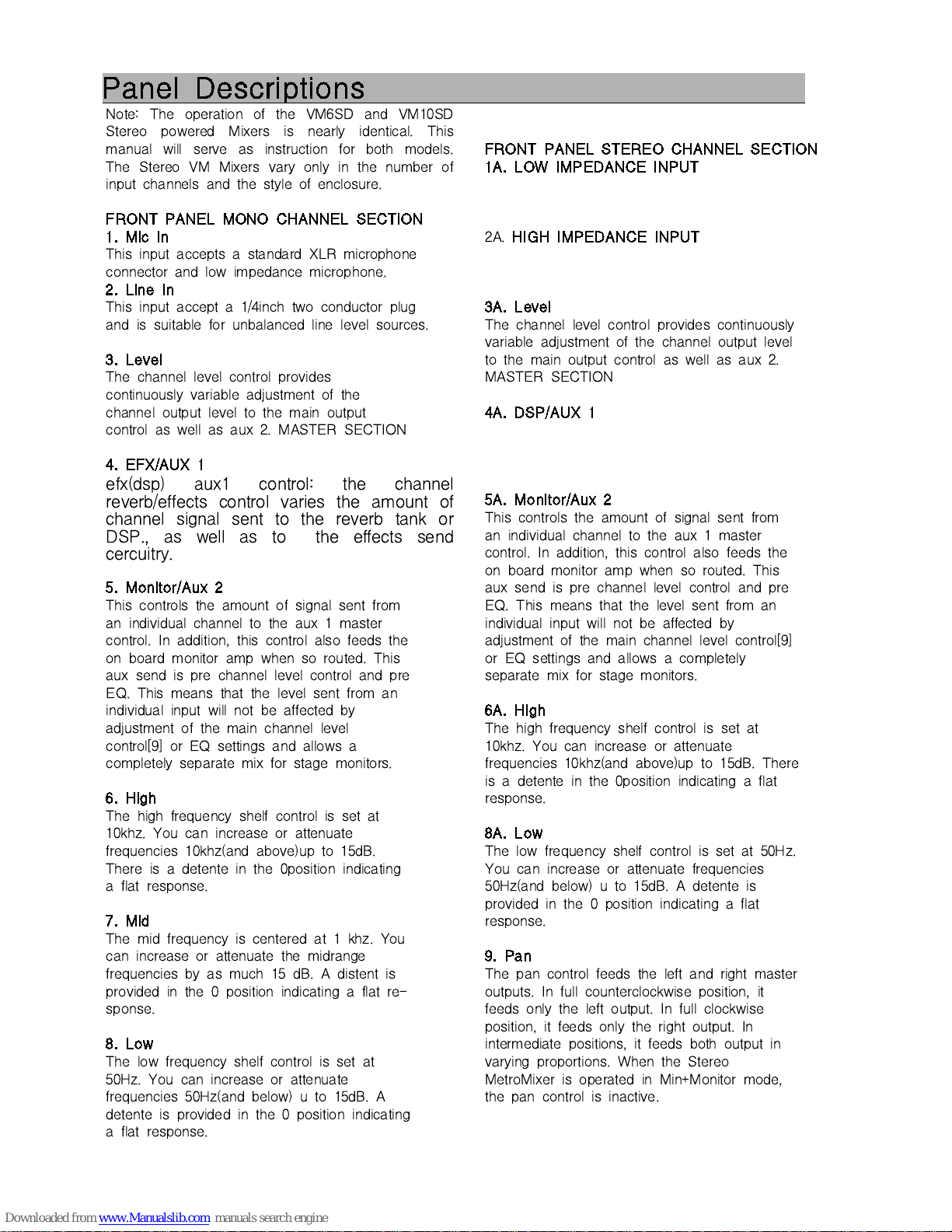
Panel Descriptions
Note: The operation of the VM6SD and VM10SD
Stereo powered Mixers is nearly identical. This
manual will serve as instruction for both models.
The Stereo VM Mixers vary only in the number of
input channels and the style of enclosure.
FRONT PANEL MONO CHANNEL SECTION
1. Mic In
This input accepts a standard XLR microphone
connector and low impedance microphone.
2. Line In
This input accept a 1/4inch two conductor plug
and is suitable for unbalanced line level sources.
3. Level
The channel level control provides
continuously variable adjustment of the
channel output level to the main output
control as well as aux 2. MASTER SECTION
4. EFX/AUX 1
efx(dsp) aux1 control: the channel
reverb/effects control varies the amount of
channel signal sent to the reverb tank or
DSP., as well as to the effects send
cercuitry.
5. Monitor/Aux 2
This controls the amount of signal sent from
an individual channel to the aux 1 master
control. In addition, this control also feeds the
on board monitor amp when so routed. This
aux send is pre channel level control and pre
EQ. This means that the level sent from an
individual input will not be affected by
adjustment of the main channel level
control[9] or EQ settings and allows a
completely separate mix for stage monitors.
6. High
The high frequency shelf control is set at
10khz. You can increase or attenuate
frequencies 10khz(and above)up to 15dB.
There is a detente in the 0position indicating
a flat response.
7. Mid
The mid frequency is centered at 1 khz. You
can increase or attenuate the midrange
frequencies by as much 15 dB. A distent is
provided in the 0 position indicating a flat re-
sponse.
8. Low
The low frequency shelf control is set at
50Hz. You can increase or attenuate
frequencies 50Hz(and below) u to 15dB. A
detente is provided in the 0 position indicating
a flat response.
FRONT PANEL STEREO CHANNEL SECTION
1A. LOW IMPEDANCE INPUT
2A.
HIGH IMPEDANCE INPUT
3A. Level
The channel level control provides continuously
variable adjustment of the channel output level
to the main output control as well as aux 2.
MASTER SECTION
4A. DSP/AUX 1
5A. Monitor/Aux 2
This controls the amount of signal sent from
an individual channel to the aux 1 master
control. In addition, this control also feeds the
on board monitor amp when so routed. This
aux send is pre channel level control and pre
EQ. This means that the level sent from an
individual input will not be affected by
adjustment of the main channel level control[9]
or EQ settings and allows a completely
separate mix for stage monitors.
6A. High
The high frequency shelf control is set at
10khz. You can increase or attenuate
frequencies 10khz(and above)up to 15dB. There
is a detente in the 0position indicating a flat
response.
8A. Low
The low frequency shelf control is set at 50Hz.
You can increase or attenuate frequencies
50Hz(and below) u to 15dB. A detente is
provided in the 0 position indicating a flat
response.
9. Pan
The pan control feeds the left and right master
outputs. In full counterclockwise position, it
feeds only the left output. In full clockwise
position, it feeds only the right output. In
intermediate positions, it feeds both output in
varying proportions. When the Stereo
MetroMixer is operated in Min+Monitor mode,
the pan control is inactive.
Page 6
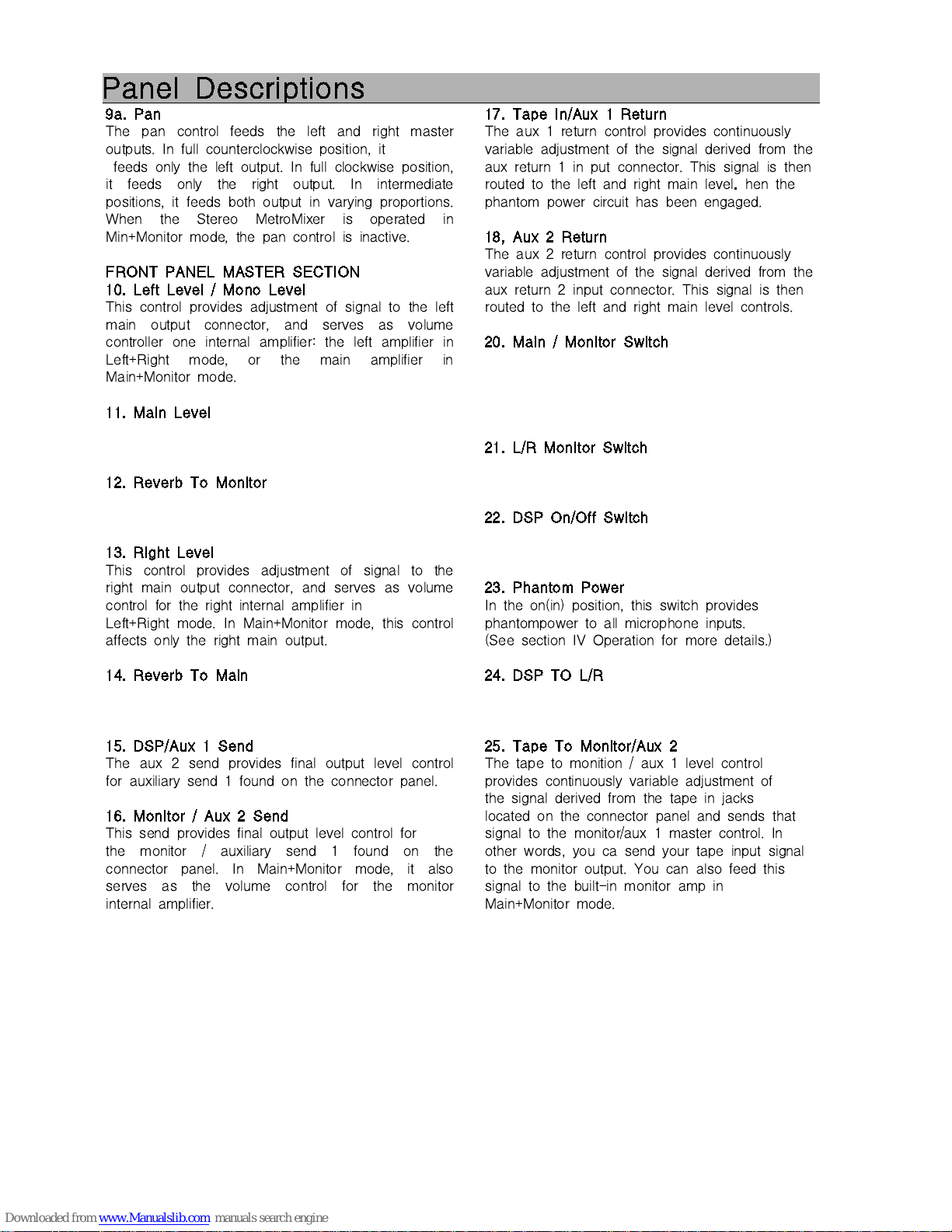
Panel Descriptions
9a. Pan
The pan control feeds the left and right master
outputs. In full counterclockwise position, it
feeds only the left output. In full clockwise position,
it feeds only the right output. In intermediate
positions, it feeds both output in varying proportions.
When the Stereo MetroMixer is operated in
Min+Monitor mode, the pan control is inactive.
FRONT PANEL MASTER SECTION
10. Left Level / Mono Level
This control provides adjustment of signal to the left
main output connector, and serves as volume
controller one internal amplifier: the left amplifier in
Left+Right mode, or the main amplifier in
Main+Monitor mode.
11. Main Level
12. Reverb To Monitor
13. Right Level
This control provides adjustment of signal to the
right main output connector, and serves as volume
control for the right internal amplifier in
Left+Right mode. In Main+Monitor mode, this control
affects only the right main output.
14. Reverb To Main
15. DSP/Aux 1 Send
The aux 2 send provides final output level control
for auxiliary send 1 found on the connector panel.
16. Monitor / Aux 2 Send
This send provides final output level control for
the monitor / auxiliary send 1 found on the
connector panel. In Main+Monitor mode, it also
serves as the volume control for the monitor
internal amplifier.
17. Tape In/Aux 1 Return
The aux 1 return control provides continuously
variable adjustment of the signal derived from the
aux return 1 in put connector. This signal is then
routed to the left and right main level.hen the
phantom power circuit has been engaged.
18, Aux 2 Return
The aux 2 return control provides continuously
variable adjustment of the signal derived from the
aux return 2 input connector. This signal is then
routed to the left and right main level controls.
20. Main / Monitor Switch
21. L/R Monitor Switch
22. DSP On/Off Switch
23. Phantom Power
In the on(in) position, this switch provides
phantompower to all microphone inputs.
(See section IV Operation for more details.)
24. DSP TO L/R
25. Tape To Monitor/Aux 2
The tape to monition / aux 1 level control
provides continuously variable adjustment of
the signal derived from the tape in jacks
located on the connector panel and sends that
signal to the monitor/aux 1 master control. In
other words, you ca send your tape input signal
to the monitor output. You can also feed this
signal to the built-in monitor amp in
Main+Monitor mode.
Page 7
Panel Descriptions
27. Graphic Equalizers
Two 9 band graphic equalizers are provided on
the front panel and may be used for Left+Right
or Main+Monitor, depending on the mode of
operation.
28. Power LED Indicator
This LED indicates that the mixer has been
switched on, and is receiving power from the AC
mains.
29. Protect LED
Illumination of this LED indicates a system
problem. The amplifier has shut down in order to
protect itself from damage due to and electronic
fault. Check all connections for proper wiring.
30. AMP CLIP
31. DEP(DIGITAL EFFECTS PROCESSOR)
MODE
32. TIME
33. Tape In Level
The tape in level control provides
continuously variable adjustment of the signal
derived from the tape in jacks located on the
connector panel. It feeds the Tape in Pan
control (10) above.
34. Main Out
The main output 1/4 inch connectors are the
final output for the main stereo mix and is
controlled by the master left and right
levelcontrols. These outputs are taken before the
built-in graphic equalizer. In Mono+Main mode,
the Left connector gives the mono sun
output(from L&R busses), and the Right
connector is not functional.
36. FOOT SWITCH
38. TAPE IN
This dual RCA output is feeds a tape recorder
with a post-master level control signal.
39. TAPE OUT
This dual RCA phono input is designed to accept
the output from a tape recorder or CD player. The
inputs sum to mono and are routed to the Left
and Right buses through the Tape In Level and
Tape In Pan controls. The tape inputs may also
be used for additional mix inputs.
40. Aux Sends
The two auxiliary outputs terminate here. They
are unbalanced line level outputs.
41. Aux Returns
Two additional inputs are provided for returning
effects devices. These additional inputs accept a
1/4 inch plug and are suitable for unbalanced line
level sources.
42. Main Bus In
These 1/4 inch inputs can be used for connecting
a source device directly to the main left and right
power amplifier sections of your powered mixer.
Inserting a connector into these jacks will
disconnect the mixer and graphic equalizer sections
from the power amplifiers.
Page 8
Panel Descriptions
. Left Level / Mono Level
This control provides adjustment of signal to the
left main output connector, and serves as volume
controller one internal amplifier: the left amplifier
in Left+Right mode, or the main amplifier in
Main+Monitor mode.
. Phantom Power Indicator
Phantom power is provided for electronic
condenser microphones that may require such
power. This LED will illuminate when the
phantom power circuit has been engaged.
. Reverb/Aux 2
Reverb/Aux2 control varies the amount of
channel signal sent to the aux 2 master
control.
The signal is post EQ and the main channel
level control and is suitable for an effects
device.
This control also feeds the built-in reverb
system.
. Tape In PAN
This control feeds the left and right master
outputs as described in 8. above. It takes its
signal from the tape in level control(13).
. Reverb Level
This rotary control acts as master reverb
control to the internal reverberation circuit.
Its signal is derived from the individual
channel reverb/ aux 2 sends. The reverb can
be defeated by turning this control to the far
left or off position.
. Compression
Your MetroMix is equipped with a built in
automatic compressor/limiter which will reduce the
chances of amplifier clipping or destortion. An
LED will illuminte when the limiter circuitry is
effcetin the output signal.
. Power Switch
This controls the AC mains power to your
powered mixer. Power is on when this switch is
in the up position and is confirmed when the
power LED indicator is illuminated.
. Power Amp Routing
This switch changes the mode of operation from
Left+Right o Main+<MOnitor mode. There are two
graphic equalizers and power amplifiers on stereo
MertroMixers. In Left+Right mode, the upper
EQ/power amplifier derives its signal fromk the
left master control, and the lower EQ/power
amplifier from the right master control. In
Main+Monitor mode, the upper EQ/power amp
receives a summed L+R main signal, while the
lower power amp receives the Monitir sugnal.
Page 9
Operation 1
B. CONNECTIONS
1. XLR Input jacks
Electronically balanced inputs accept a standard
XLR male connector. Pin1=ground, pin2=cold or
nrgative (-) and pin3=hot or oisutuve (+) (see Figure
2). These connectors should be utilized for low
impedance microphones. If you are using a high
impedanced microphone, it will likeiy have a cord
with a1/4 inch connector on it. In this case, it would
be appropriate to plug such microphones into a line
input, however performance, we recommend you
invest in one of the many higher quality, liw
impedance mics available on the market, or
alternatively, purchase an impedance matching
transformer from your dealer.
2. 1/4 Inch Phone Input Jacks
These tip / sleeve jacks accep0t an unbalanced line
level signal using a narmal male phone plug. (see
Figure 2.)
3. Speaker Output Jacks
The speaker output jacks are 1/4 inch two
conductor jacks. Their power output and functin are
dependent upon the particular unit that you are
using.
4. RCA Phono Jacks
The RCA jacks accept unbalanced male pin
connectors.
C. BASIC OPERATIONS MODES
a. FEMALE THREE PIN CONNECTOR
b. UNBALANCED 1/4'' CONNECTOR
Before you begin your connections, you must
decide how you will configure your sound system.
Below ate three different system variations that can
ve used with your powered mixer. Carefully consider
all of them to decide which system you will use.
NOTE; The Wtereo metro Mixers feature flexible
patching options which make possible more
variations of setup than are presented here. Once
familiarized with the unit's capabilities, you should
be able to cahieve practically any serup you desire.
SYSTEM 1.
Powered Stereo Operation
For this most basic stereo powered mono mixer
operation, you will need to commect:
* 1 or more input source devices such as a
microphone, keyboard, CD player or tape deck.
* An outboard effect processor such as a digital
reverb unit. (optional)
* Two or four main speaker systems, divided
equally among the Lefr and Right outputs.
SYSTEM 2.
Internally powered Stereo Operation with
Sparately Powered Monitor Speakers
1 or more input source devices such as a
microphone,keyboard, CD player or tape deck.
An outboard effects processor such as a digital
reverb unit (optionsl)
two or four main speaker systems, divided
equally among the Left and Right outputs.
1 graphic equalizer for equalizing the monitor
wywtem.
1 external power amplifier for the monitor
speakers.
1 or more monitpr speaker systems.
SYSTEM 3.
Main + Monitor Powered Operation
This is a very popular alternative use of the two
power amplifier channels. One output, the sum of left
and right buses, is used for the
Main(audience)speakers, and the other output for
Monitor speakers.
This setup requires:
1 or more input source devices such as a
,ocrp[jpme, keyboard, CD player or tape deck.
An outboard effects processor such as a digital
reverb unit. (optional)
1 or more main speaker systems.
1 or more monitor speaker systems.
D. SYSTEM CONNECTION
Now that you have decided which mode and type of
system operation you will use, you are ready to make
your system connections and settings on your Stereo
MetroMix.
CAUTION:
Before proceeding, make sure that are to ve
connected have been switched OFF.
1. Input Selection
Both the mic and line inputs on each channel are
active at the same time. You should be sure only
one device or instrument is connected to a channel
input at one time. Connection of more than one
device could cause undesirable results.
Page 10
Operation 2
SYSTEM 1.
Powered Stereo Operation
For this most basic stereo powered mono mixer
operation, you will need to commect:
1 or more input source devices such as a
microphone, keyboard, CD player or tape deck.
An outboard effect processor such as a digital
reverb unit. (optional)
Two or four main speaker systems, divided
equally among the Lefr and Right outputs.
SYSTEM 2.
Internally powered Stereo Operation with
Sparately Powered Monitor Speakers
1 or more input source devices such as a
microphone,keyboard, CD player or tape deck.
An outboard effects processor such as a digital
reverb unit (optionsl)
two or four main speaker systems, divided
equally among the Left and Right outputs.
1 graphic equalizer for equalizing the monitor
wywtem.
1 external power amplifier for the monitor
speakers.
1 or more monitpr speaker systems.
SYSTEM 3.
Main + Monitor Powered Operation
This is a very popular alternative use of the two
power amplifier channels. One output, the sum of
left and right buses, is used for the
Main(audience)speakers, and the other output for
Monitor speakers.
This setup requires:
1 or more input source devices such as a
,ocrp[jpme, keyboard, CD player or tape deck.
An outboard effects processor such as a digital
reverb unit. (optional)
1 or more main speaker systems.
1 or more monitor speaker systems.
D. SYSTEM CONNECTION
Now that you have decided which mode and type
of system operation you will use, you are ready to
make your system connections and settings on your
Stereo MetroMix.
CAUTION:
Before proceeding, make sure that are to ve
connected have been switched OFF.
1. Input Selection
Both the mic and line inputs on each channel are
active at the same time. You should be sure only
one device or instrument is connected to a channel
input at one time. Connection of more than one
device could cause undesirable results.
2. Connector Audio Sources to Inputs
Using Section B Connections as a guide, you can
now connect microphones and line level devices to
the appropriate input jacks. Decide which channels
will be used for mics and which, if any, will be used
for instruments. Grouping your vocal and instrument
channels makes using the mixer eaaier during the
mixing porcess. If you will be feeding a signal from a
rape or CD player into the mixer, connect this now,
as well. Connect a stereo RCA cable frim the output
jacks of the tape or CD player to the tape in
jacks on your powered mixer. Additionally, you may
wish to make a recording of the program passing
through your mixer. If so, connect another stereo
cable from the tape out jacks of the mixer to the
input jacks ofm ypur tape recorder.
3. Connect External Effects Dvices
Your powered mixer is compatible with and can be
connected to external effects processors such as
reverb devices. You can utilize either or both of the
auxiliary sends available on your mixer. Note that
Mon/Aux 1 is not affected by each channel's level
control (it is prefader). It is appropriate for use with
monitors. The contribution from each channel to Aux
2 is post fader, and is affected by the level control of
each channel. Aux 2 is more often used for effect
use.
Example:
Connect a standard 1/4inch, shielded cable between
the Aux 2 send jack and the input of a reverb
device. Connect the oytput of that same device to
aux return 2 on your mixer. Inthis particular case, you
will feed both the internal reverb unit and the external
reverb device simultaneously. The external device will
have its input controlled by the aux w send level
control. The ineternal reverb will be controlled by the
reverb level control located on the front panel. The
external reverb device will have its output signal
returned to the main inx via the aux return 2 level
control. there are serverb device will have its output
signal returned to the main mix via the aux return 2
level control. There are several controls in this effect
chain that need to be properly set as each one has
a different effect on the signal. The amount of reverb
or effect per channel is reguated by the channel
reverb/aux 2 control which deteermines how much of
that channel's signal will be sent out of the mixer to
the effects processor. After the processor has had its
effect on the signal, the resultant processed signal
must be brought back into the mixer so you can
blend it with the regular signal coming from each
channel. This is dong through the aux 2 return jack
and the amount of the signal is regulated by the aux
2 return control.
4. System Specific Connections
Of the three sample systems described in section C,
each has its own system specific connections. Find
the system you are going to use to complate the
remaining connections
Page 11
Operation 3
SYSTEM 1.
Powered Stereo Operation
A. Speaker Connection
Connect your main or "house" speaker systems to
the Left and Right speaker output jacks on the rear
panel of the mixer. Use heavy gauge, unshielded
speaker cables.
Note:
The total speaker impedance load must be at least
2 Ohms. Thix means you can use a maximum of
four speaker systems with an impedanced of 8
Ohms each. If you are not sure of your total
speaker impedance load, contact your dealer for
more information. Your system is now properly
connected and ready to use. Proceed to Section E.
System Operation.
SYSTEM 2.
Internally Powered Stereo Operation with
Separately Powered Monltor Speakers
A. Speaker Connection
Connect your main or "house" speaker systems to
the Left and Right speaker output jacks on the rear
panel of the mixer. Use heavy gruge, unshielded
speaker cables.
Note:
The total speaker impedance load must be at least
2 Ohms. In simple terms, this means you can use
a maximum of foru speaker systems with an
impedance of 8 Ohms each. If you are not sure of
your total speaker impedance load, contact your
deale for more information.
B. External EQ Connection
If you will not be using a graphic equalizer in your
monitor system, go on to step C. Connect your
monitor system by extending a 1/4 inch shielded
cable from the Monitor/Aux 1 send output of your
powered mixer to the input of the monitor system
graphic EQ.
C. External Power Amp Connection
Connect the output of the external graphic equalizer
to input of the external power amplifier using a
shielded cable.
D. Monltor Connection
Connect the ,onitor speaker system(s) to the output
of the ezternal amplifier. Use heavy gruge,
unshielded speaker cables. Your sustem is now
properly connected and ready to use. Preceed to
section E. System Operation.
SYSTEM 3.
Main + Monitor Powered Operation
A. Speaker Connection
Connect the main speaker system(s) to the Main
Speaker output. Connect the monitor speaker(s) to
the Monitor Speaker output. Use heavy gauge.
unshielded speaker cables. Note that the total
speaker impedance load must be at least 2 Ohms.
Insimple terms, the this means you can use a
maximum of four monitor speaker sustems with an
impedance of 8 Ohms eacj. If uou are not sure of
your total speaker impedance load, contact your
dealer for more information. UYour system is now
roperly connected and ready to use. Proceed to
section E. system Operation.
E. MAIN SYSTEM OPERATION
you are nearly ready to switch on the power to your
Stereo MetroMix powered mixer and other
unitsconnected to it. There are only a few more
things to take care of before doing so.
1. Set the EQ / Power Amp Routing Switch
This setting is dependent on the type of system
operation you have selected. Find your system below
for the proper EQ / Power Amplifier royting switch
srtting.
SYSTEM 1.
Switch in the Left / Right (in) position.
SYSTEM 2.
Switch in the Left / Right (in) powition.
SYSTEM 3.
Switch in the MAIN / MONITOR (out) position.
2. Set Phantom Power Switch
A 15 volt DC phantom power supply is proviced for
electret condenser microphones that may require such
power. Place the phantom power switch in the ON
(in) position only if a microphone connected to the
mixer repuires it.
Note:
Phantom p0ower applied to the output of a keyboard,
effcets device or similar sound module could possibly
damage that device's circuits. It may be harmful to
connect anything except a micro0phone into any XLR
input on the mixer when using phantom power. Be
sure the phantom power is switched off (out [position)
befor makin any connections. The status of this
switch should only be changed when the unit is
switched off.
3. Switch Power On
Re-check all connections one more time before
proceeding. Set all level controls on your powered
mixer any external units you have connected to
minimum. Graphic equalizer sliders should be set at
zero - the detented, center position. Chnnel equalizer
controls should be set to the zero or center position.
You may now safely switch on the power to all
equipment connected to your powered mixer and then
switch on the powered mixer itself. Because you still
have all the level controls set to zero, you should
hear nothing.
Page 12
Operation 4
4. Adjust Channel Input Gain
This is always the first adjustment to be made
no matter which system type you have chosen.
It can be done without hearing yout actual
signal. This adjustment is critical and must be
correct as it affects the performance of your
entire sustem. Let's start with one of your mic
channels that will be used for vocals.
4a. Reduce Level Control
The channel level control should remain in the 0
mor off position,
4b. Sound Check
Set the input gain control at half (5). If you are
the person who will ge speaking or singing into
that microphone, please proceed. If not, that
person will need to repeatedly speak or sing into
the microphone at the loudest level they will sue
during the performance or event.
4c. Establlsh Program Peak
Slowly turn the gain control clockwise until the
peak LED begins to flash.
4d. Re-adjust Gain
Reduce or re-adjust the gain control until the
LED begins to flash only on the loudest words
or singing parts (called prgram "peak").
4e. Set Addltional Inputs
You must mpw follow this procedure for each
microphone and line input.
4f. Addltional Information
The peak indicator will flash when the audio
signal reaches 6 dB beliw the actual distortion
point. Setting the gain too high will result in the
LED stauing on all the time and there will be
audible distortion. It is important for the LED to
flash occasionally. If you don't see the LED
fiashing, it is bacause your trim is set too low.
Setting your gain too low may force you to
operate the channel level control all the way to
the right and you still may not have enoug
output level from that channel. Additionally, a
low setting at the input requires that you raise
the level of other devices in the signal path
higher than normal, increasing unwanted noise in
youjr sound system.
5. Set Main System Level Control
In Stereo mode, the main volume controls for
your system will be the Left and Right Main
level controls on your powered mixer. In
Main/Monitor mode, the main volume controls
will be the Main and Monitor level controls. If
you are using SYSTEM 1 or SYSTEM 3,
proceed to step 5c. For SYSTEM2, go to the
next step:
5a. Set External EQ Input Level
Set the input level control on the external
graphic equalizer to about 60%. You will need to
re-check this setting later to be sure there is no
clipping or distortion.
5b. Set External Power Amp Input Level
Set the input level control on the external power
amplifier to about 60%. You will need to re-chek
this setting later to be sure there is no clipping
or distortion.
5c. Set MetroMix Master Level
To begin adjusting your sound it is recommended
that you turn the master Left and Right volume
controls to the 3 posilion. You will prbably raise
this to a higher setting at a later time after you
have established proper gain and safe operating
levels. Use this as a starting point. You are going
to poerate the indivdual channels higher than the
main. Bacause of this, you should be conserbvative
with the main livel output control.
6. Set Channel Level Control
The channel level control allows you to separately
control each individual input's contribution to the
main output mix. Adjustment of this control will
also affect the level of reverb/aux 2 signal sent
from an individual channel.
6a. Set Channel Level
Slowly raise the level on each individual channel
unitl the optimum volume is achieved, or, when
using a microphone, slowly raise the level until
you begin to hear feeback. If you start to hear
feedback you should quickly reduce that channel
control back to 0 or until the feedback stops.
6b. Increase Channel Level
Carefully raise the level control again, stopping
befor the point at which you experienced feedback.
If feedback persists, reduce levels to 0 and refer to
section V1 Professional Operating Tips of this
manual. Proper equalization is very important to
the optimum operation of any sound system. If
after following out suggestions on micropjhpme
and speaker placement you still experience
feedback, it may be that this is simply the highest
level that you can operate the sustem at in that
given environment. Conversely, if you have raised
the channel level control to approximately three
quatrer volume (7position) and feel that you need
more volume, slowly increase the main output
levelo control until you reach optimum level or
until feedback is detected, whichever is lower.
7. Adjust ccChannel Equallzation
It is the equalizer section of each channel that
actually shapes the tonality of your sound.
Whether you are reproducing the sound of a violin
or a tractor, tge reakusn if tgat sound is entirely
dependent on how you have adjusted the EQ.
Therefore, the EQ section can be your best friend
or worst enemy in a difficult audio situation. Be
careful not to "over-EQ" your sound sustem.
Many speakers are damaged as a result of
equalizer induced distortion.
7a. Equallzation Startubg Point
Begin your operation with the three eqyalization
controls in the zero or "detent"opsition. Slowly add
tonal adjustments to suit your needs. It is better
to make slow and gradual changes to each
equalization band than to turn the controls up
rapidly.
7b. Subtractive Equalization
If you feel that you need more than 10-12 dB fo
boost in your low or high EQ, you need to look
elsewhere in your system for a problem. Over
equalization can be harmful to your system.
Sometimes, less gives you more. Reduce your mid
frequencies in order to accentuate the highs and
lows. this practice is commonly referred to as
"subtractive equalization". In other words, rather
than turning everything up, try turning parts
down.
Page 13
Operation 5
8. Using the Internal Reverb
To make use of the internal reverb, begin with
the reverb/aux 2 send level on the indivedual
channel you wosh to affect set at the 5 postiton.
Raise the reverb level control on the master
section to a level that accomplishes the effect
you desire. If you find thart you want to hear
more effect, raise the reverb/aux 2 level on the
channel. If after raising the channel level control
as high as the 7 position and you still would
,like more reverb, raise the reverb level control
in the master section.
9. Using External Effects Devices
Before using an external dffects device with your
powered mixer, read the instructing manual for
the external device. The reverb/aux 2 send
receices its signal after the EQ and after the
channel level control. This makes them ideal for
external reverb and effects devices. Once you
have set the basic amount of effects level, the
external device will have its input controlled by
the master send level control. The external
reverb device will have its output signal returned
to the mix via one of the aux return level
controls.
8a. Set Master Aux Send
Begin by setting the master aux send you have
chosen to approximately the 5 position.
8b. Set External Input's Gain
If you external device has a unity gain position
on the input, set the external device there now.
8c. Set Aux Send Program Peak
Rasie the individual aux send levels on your
powered mixer until you see the peak indicator
on the external device flash on signal peaks.
Adjusting the input gain level to the external
effects processor is not unlike the operation you
performed when you set up the channel gain
controls on your powered mixer. The peak
indicator LED on the effects unit (if it has one)
should flash during program peaks just like the
LED's on your mixer.
8d. Adjust Outboard Effects Level
The effects processor may have an output level
control that needs setting as well. Once you have
eastablished proper gain settings you may now
raise the output level on the effects device to
approximately the 5 position. Now you are ready
to return the processed signal to the powered
mixer for blending with the regular, unaffected
signal in the main mix.
8e. Adjust Aux Return Level
Slowly raise the level of the aux return control
connected to the output of the effects device
(probably aux 2 return) until you heat the
desired effect. If you hear distortion, check to see
that the effects device's peak input. it is some
what subjective as to whether an effect sounds
proper. it is largely a matter of taste. However,
be using external devices. See section V1
Professional Operating Tips for more information.
10. Readjust Main Level Control
The main level control is the final level control for
the system's main output whether you are using
internal or external power amplification and
controls the amount of power applied to your
speakers. If you are happy with the general sound
of your mix but require more general volume. you
should gradually increase the main level control to
achieve the desired volume level. Only after you
have set your individual channels to approximately
therr quarter volume should you raise your main
level control. You will find that adding channel
equalization and reverb can affect the over-all
volume. Keepthis in mind when adjusting the
channel and main volume. Keep this in nmind
when adjudting the channel and main volume
levels. Always make any changes or adjustments
in a sliw and gradual manner to avoid feedback
and very loud transients. Both can damage your
speaker systems, not to mention your hearing.
11. Using Tape In
The tape input is suited to cassette decks, CD
players and devices with similar output lwvels.
The tape level control will serve as the only
control for this input as it goes directly into the
main mix. Note also that the Tape input may be
used as two additional inputs or "return".
11a. Adjust Tapee Level Control
With your poay back tape deck or CD connected
to your powered mixer, solwly raise the tape level
control until you reach optimum listening levels.
11b. Adjust Tape In Pan Control
The source connected to the Tape in jacks may be
panned to the left or right buses, or any
intermediate position using the Tape In Pan
control.
11c. Adjust Tape to Monitor Level Control
The tape to monitor/aux 1 level control is
dependent on the tape level control. Adjustments
to the tape level control affect the level of your
tape or CD player sent to the aux 1 (monitor)
send. When using tape play back in the monitor
system, we recommend that you balance the tape
to monitor/aux 1 levels with yout other sources
while the main or house mix level is down. This
will help you to better determine optimum
monitoring levels.
12. Using Tape Out
The main level control will control the level of
signal sent to the tape out jack aoolwing you to
make a recording of the main mix. If you record
on the same machine you have connected to the
tape in jacks.
you must set the tape in level at 0. Failure to do
so will result in electronic feedback. The resultant
oscillation will ruin your recording.
Page 14
Operation 6
10. Readjust Main Level Control
The main level control is the final level control
for the system's main output whether you are
using internal or external power amplification and
controls the amount of power applied to your
speakers. If you are happy with the general
sound of your mix but require more general
volume. you should gradually increase the main
level control to achieve the desired volume level.
Only after you have set your individual channels
to approximately therr quarter volume should you
raise your main level control. You will find that
adding channel equalization and reverb can affect
the over-all volume. Keepthis in mind when
adjusting the channel and main volume. Keep
this in nmind when adjudting the channel and
main volume levels. Always make any changes
or adjustments in a sliw and gradual manner to
avoid feedback and very loud transients. Both
can damage your speaker systems, not to
mention your hearing.
11. Using Tape In
The tape input is suited to cassette decks, CD
players and devices with similar output lwvels.
The tape level control will serve as the only
control for this input as it goes directly into the
main mix. Note also that the Tape input may be
used as two additional inputs or "return".
11a. Adjust Tapee Level Control
With your poay back tape deck or CD connected
to your powered mixer, solwly raise the tape
level control until you reach optimum listening
levels.
11b. Adjust Tape In Pan Control
The source connected to the Tape in jacks may
be panned to the left or right buses, or any
intermediate position using the Tape In Pan
control.
11c. Adjust Tape to Monitor Level Control
The tape to monitor/aux 1 level control is
dependent on the tape level control. Adjustments
to the tape level control affect the level of your
tape or CD player sent to the aux 1 (monitor)
send. When using tape play back in the monitor
system, we recommend that you balance the tape
to monitor/aux 1 levels with yout other sources
while the main or house mix level is down. This
will help you to better determine optimum
monitoring levels.
12. Using Tape Out
The main level control will control the level of
signal sent to the tape out jack aoolwing you to
make a recording of the main mix. If you record
on the same machine you have connected to the
tape in jacks.
you must set the tape in level at 0. Failure to do
so will result in electronic feedback. The
resultant oscillation will ruin your recording.
F. MONITOR SYSTEM OPERATION
The whole purpose of a monitor system is to
provide a completely independent mix of your
input channels that can be sent to stage monitor
speakers. This is so that the performers can heat
what they ate dointg, Because of speaker
placement, program material and other factors, it
is rare that the monitor mix will be the same sa
the main or house mix. Your powered mixer has
the capability of using aux 1 as a completly
separate monitor mix that can be sent either to an
outside EQ / amplifier and speakers or this mix
can be sent to the internal EQ / amplifier.Of the
three systems discussed during serup and
operation, system one does not provide for
monitors. For those that do, will now show you
how to use the monitor system. Since this mix is
separate from the house or main mix, there is no
need to have the main mix set to an audible level.
Therefore, all of these instructions ard based on
the premise that you will have the main level
control set to 0. All of your other mixer settings
should remain in place since we will be needing
them as soon as we have set up the monitor
system.
Note: Nomonitors are used in SYSTEM 1. If your
system requires monitors, please consider systems
similar to 2 or 3.
MONITOR OPERATION for System 2.
1. Adjust EXternal Monltor EQ
With the main level and aux 1 master send
controls set to 0, set the input level control on the
external graphic equalizer to about 60%. You will
need to re-check this setting later to be sure there
is no clipping or distortion.
2, Set External Power Amplifier
Set the input level control on the external power
amplifier to about 60%. You will need to re-check
this setting later to be sure there is no clipping or
distortion.
3. Adjust Master Aux 1 Control
Set the aux 1 master send control to 4. You will
likely have to re-adjust this later but for now, this
settin will allow you to heat your monitor system
and decide what further adjustments ate necessary.
4. Adjust Channel Monitor / Aux 1 Controls
Decide which channels you want to include in
your monitor mix. Ser a nominal level on each of
these channels using the monitor / aux 1 channel
level control. Slowiy raise the level on each
individual channel until the optimum volume is
achieved or, when using a microphone, solwoy
raise the level until you begin to heat feedback. If
you start to hear feedback you should quickly
reduce that channel control back to 0 or until the
feedback stops.
5. Adjust Channel Aux 1 Level Control
Carefully raise the level control again, stopping
before the point at which you experienced
feedback. If feedback persists, reduce levels to 0
and refer to section V1 Professional Operating
Tips of this manual.
6. Reset Aux 1 Master Control
Furth dajustment of the monitor system will be
necessary after you have 0properly set the graphic
equalizer. When you have completed all
adjustments to the monitor system, you can
resume the setting of the main level control for
the house system.
Page 15
Operation 7
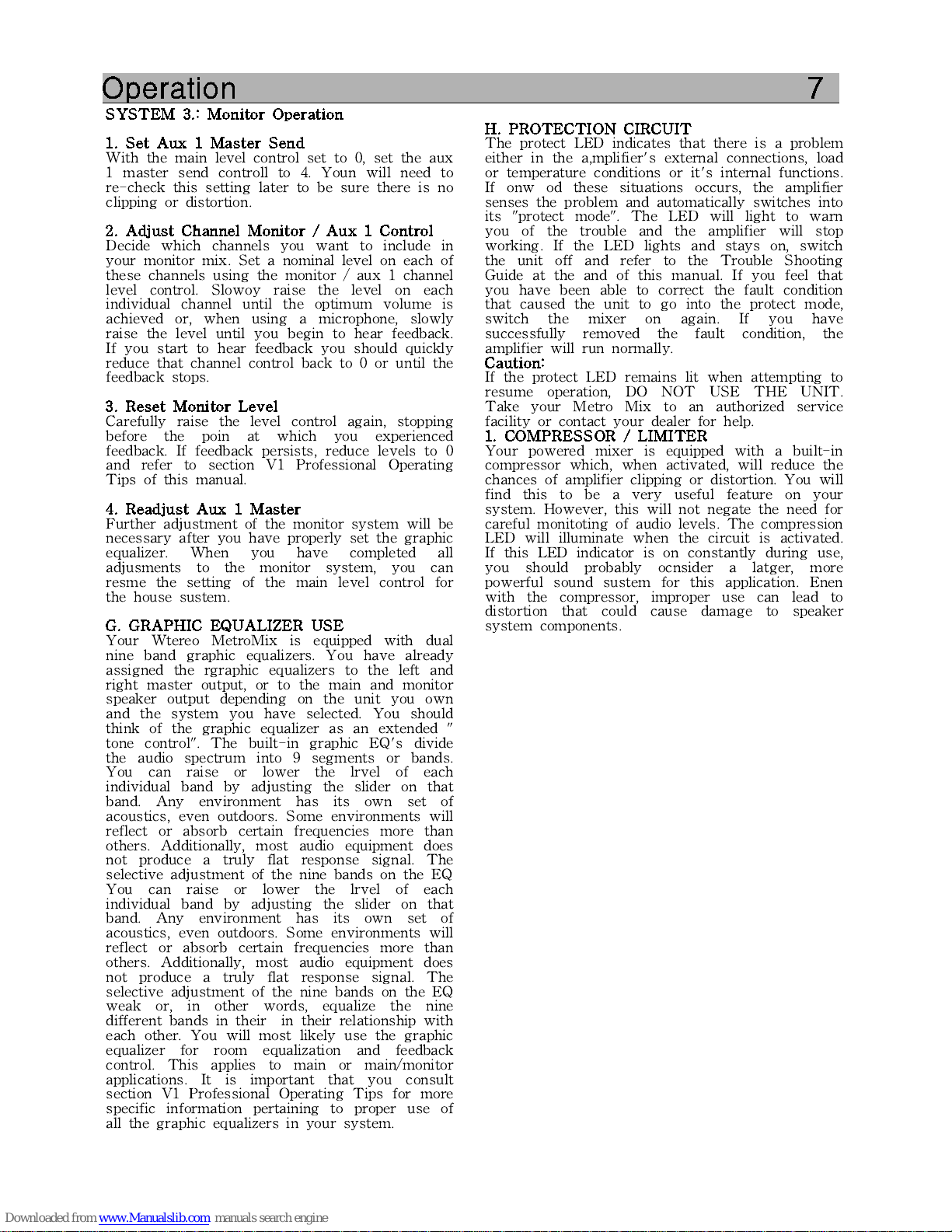
SYSTEM 3.: Monitor Operation
1. Set Aux 1 Master Send
With the main level control set to 0, set the aux
1 master send controll to 4. Youn will need to
re-check this setting later to be sure there is no
clipping or distortion.
2. Adjust Channel Monitor / Aux 1 Control
Decide which channels you want to include in
your monitor mix. Set a nominal level on each of
these channels using the monitor / aux 1 channel
level control. Slowoy raise the level on each
individual channel until the optimum volume is
achieved or, when using a microphone, slowly
raise the level until you begin to hear feedback.
If you start to hear feedback you should quickly
reduce that channel control back to 0 or until the
feedback stops.
3. Reset Monitor Level
Carefully raise the level control again, stopping
before the poin at which you experienced
feedback. If feedback persists, reduce levels to 0
and refer to section V1 Professional Operating
Tips of this manual.
4. Readjust Aux 1 Master
Further adjustment of the monitor system will be
necessary after you have properly set the graphic
equalizer. When you have completed all
adjusments to the monitor system, you can
resme the setting of the main level control for
the house sustem.
G. GRAPHIC EQUALIZER USE
Your Wtereo MetroMix is equipped with dual
nine band graphic equalizers. You have already
assigned the rgraphic equalizers to the left and
right master output, or to the main and monitor
speaker output depending on the unit you own
and the system you have selected. You should
think of the graphic equalizer as an extended "
tone control". The built-in graphic EQ's divide
the audio spectrum into 9 segments or bands.
You can raise or lower the lrvel of each
individual band by adjusting the slider on that
band. Any environment has its own set of
acoustics, even outdoors. Some environments will
reflect or absorb certain frequencies more than
others. Additionally, most audio equipment does
not produce a truly flat response signal. The
selective adjustment of the nine bands on the EQ
You can raise or lower the lrvel of each
individual band by adjusting the slider on that
band. Any environment has its own set of
acoustics, even outdoors. Some environments will
reflect or absorb certain frequencies more than
others. Additionally, most audio equipment does
not produce a truly flat response signal. The
selective adjustment of the nine bands on the EQ
weak or, in other words, equalize the nine
different bands in their in their relationship with
each other. You will most likely use the graphic
equalizer for room equalization and feedback
control. This applies to main or main/monitor
applications. It is important that you consult
section V1 Professional Operating Tips for more
specific information pertaining to proper use of
all the graphic equalizers in your system.
H. PROTECTION CIRCUIT
The protect LED indicates that there is a problem
either in the a,mplifier's external connections, load
or temperature conditions or it's internal functions.
If onw od these situations occurs, the amplifier
senses the problem and automatically switches into
its "protect mode". The LED will light to warn
you of the trouble and the amplifier will stop
working. If the LED lights and stays on, switch
the unit off and refer to the Trouble Shooting
Guide at the and of this manual. If you feel that
you have been able to correct the fault condition
that caused the unit to go into the protect mode,
switch the mixer on again. If you have
successfully removed the fault condition, the
amplifier will run normally.
Caution:
If the protect LED remains lit when attempting to
resume operation, DO NOT USE THE UNIT.
Take your Metro Mix to an authorized service
facility or contact your dealer for help.
1. COMPRESSOR / LIMITER
Your powered mixer is equipped with a built-in
compressor which, when activated, will reduce the
chances of amplifier clipping or distortion. You will
find this to be a very useful feature on your
system. However, this will not negate the need for
careful monitoting of audio levels. The compression
LED will illuminate when the circuit is activated.
If this LED indicator is on constantly during use,
you should probably ocnsider a latger, more
powerful sound sustem for this application. Enen
with the compressor, improper use can lead to
distortion that could cause damage to speaker
system components.
Page 16
Operation 8
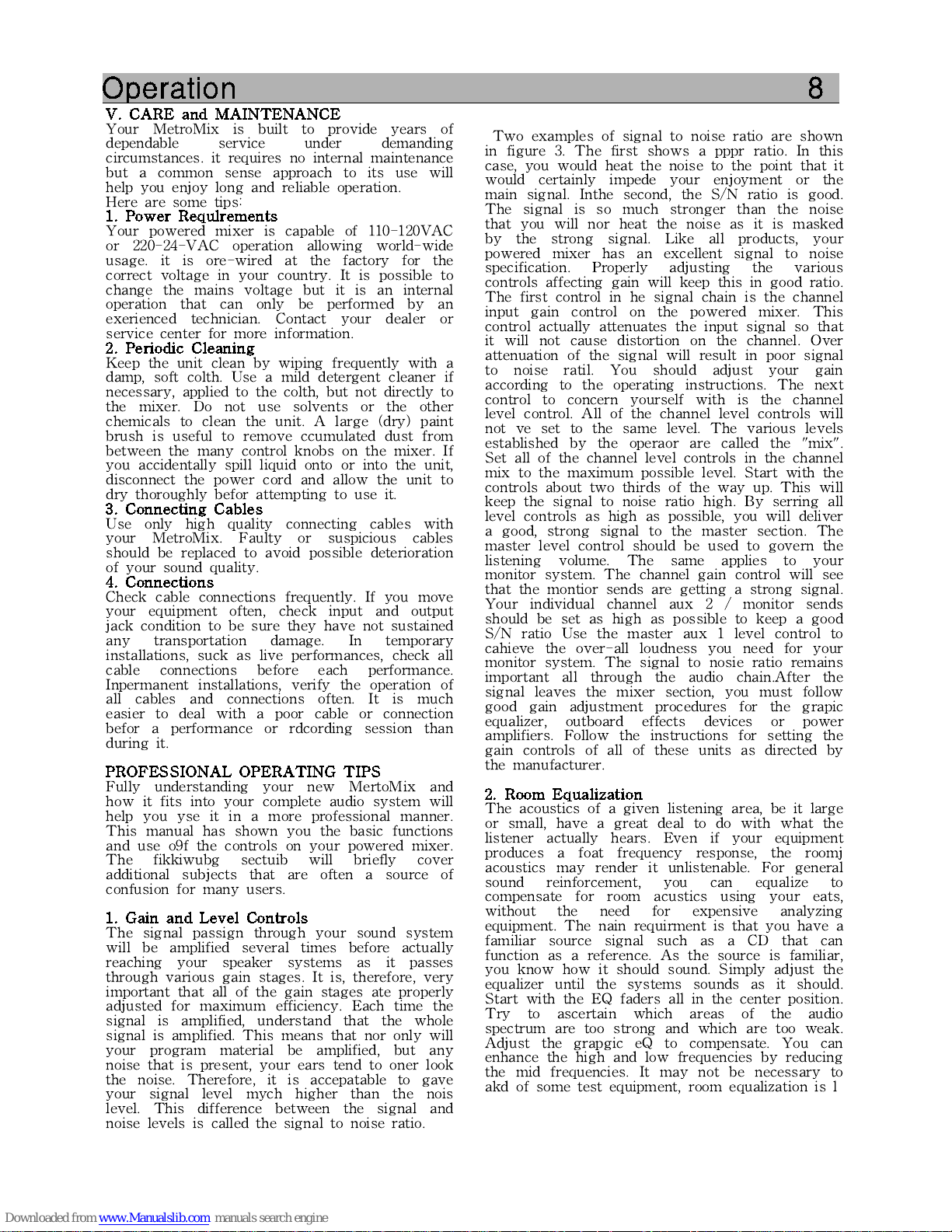
V. CARE and MAINTENANCE
Your MetroMix is built to provide years of
dependable service under demanding
circumstances. it requires no internal maintenance
but a common sense approach to its use will
help you enjoy long and reliable operation.
Here are some tips:
1. Power Requlrements
Your powered mixer is capable of 110-120VAC
or 220-24-VAC operation allowing world-wide
usage. it is ore-wired at the factory for the
correct voltage in your country. It is possible to
change the mains voltage but it is an internal
operation that can only be performed by an
exerienced technician. Contact your dealer or
service center for more information.
2. Periodic Cleaning
Keep the unit clean by wiping frequently with a
damp, soft colth. Use a mild detergent cleaner if
necessary, applied to the colth, but not directly to
the mixer. Do not use solvents or the other
chemicals to clean the unit. A large (dry) paint
brush is useful to remove ccumulated dust from
between the many control knobs on the mixer. If
you accidentally spill liquid onto or into the unit,
disconnect the power cord and allow the unit to
dry thoroughly befor attempting to use it.
3. Connecting Cables
Use only high quality connecting cables with
your MetroMix. Faulty or suspicious cables
should be replaced to avoid possible deterioration
of your sound quality.
4. Connections
Check cable connections frequently. If you move
your equipment often, check input and output
jack condition to be sure they have not sustained
any transportation damage. In temporary
installations, suck as live performances, check all
cable connections before each performance.
Inpermanent installations, verify the operation of
all cables and connections often. It is much
easier to deal with a poor cable or connection
befor a performance or rdcording session than
during it.
PROFESSIONAL OPERATING TIPS
Fully understanding your new MertoMix and
how it fits into your complete audio system will
help you yse it in a more professional manner.
This manual has shown you the basic functions
and use o9f the controls on your powered mixer.
The fikkiwubg sectuib will briefly cover
additional subjects that are often a source of
confusion for many users.
1. Gain and Level Controls
The signal passign through your sound system
will be amplified several times before actually
reaching your speaker systems as it passes
through various gain stages. It is, therefore, very
important that all of the gain stages ate properly
adjusted for maximum efficiency. Each time the
signal is amplified, understand that the whole
signal is amplified. This means that nor only will
your program material be amplified, but any
noise that is present, your ears tend to oner look
the noise. Therefore, it is accepatable to gave
your signal level mych higher than the nois
level. This difference between the signal and
noise levels is called the signal to noise ratio.
Two examples of signal to noise ratio are shown
in figure 3. The first shows a pppr ratio. In this
case, you would heat the noise to the point that it
would certainly impede your enjoyment or the
main signal. Inthe second, the S/N ratio is good.
The signal is so much stronger than the noise
that you will nor heat the noise as it is masked
by the strong signal. Like all products, your
powered mixer has an excellent signal to noise
specification. Properly adjusting the various
controls affecting gain will keep this in good ratio.
The first control in he signal chain is the channel
input gain control on the powered mixer. This
control actually attenuates the input signal so that
it will not cause distortion on the channel. Over
attenuation of the signal will result in poor signal
to noise ratil. You should adjust your gain
according to the operating instructions. The next
control to concern yourself with is the channel
level control. All of the channel level controls will
not ve set to the same level. The various levels
established by the operaor are called the "mix".
Set all of the channel level controls in the channel
mix to the maximum possible level. Start with the
controls about two thirds of the way up. This will
keep the signal to noise ratio high. By serring all
level controls as high as possible, you will deliver
a good, strong signal to the master section. The
master level control should be used to govern the
listening volume. The same applies to your
monitor system. The channel gain control will see
that the montior sends are getting a strong signal.
Your individual channel aux 2 / monitor sends
should be set as high as possible to keep a good
S/N ratio Use the master aux 1 level control to
cahieve the over-all loudness you need for your
monitor system. The signal to nosie ratio remains
important all through the audio chain.After the
signal leaves the mixer section, you must follow
good gain adjustment procedures for the grapic
equalizer, outboard effects devices or power
amplifiers. Follow the instructions for setting the
gain controls of all of these units as directed by
the manufacturer.
2. Room Equalization
The acoustics of a given listening area, be it large
or small, have a great deal to do with what the
listener actually hears. Even if your equipment
produces a foat frequency response, the roomj
acoustics may render it unlistenable. For general
sound reinforcement, you can equalize to
compensate for room acustics using your eats,
without the need for expensive analyzing
equipment. The nain requirment is that you have a
familiar source signal such as a CD that can
function as a reference. As the source is familiar,
you know how it should sound. Simply adjust the
equalizer until the systems sounds as it should.
Start with the EQ faders all in the center position.
Try to ascertain which areas of the audio
spectrum are too strong and which are too weak.
Adjust the grapgic eQ to compensate. You can
enhance the high and low frequencies by reducing
the mid frequencies. It may not be necessary to
akd of some test equipment, room equalization is l
Page 17

System Hookup diagram
1. POWERED MONO
Page 18

System Hookup diagram
1. POWERED STEREO
Page 19

Block diagram Stereo VM mixer
Page 20

Block diagram Mono VM mixer
Page 21
General Specification
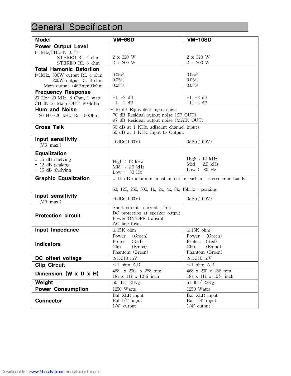
Model
VM-6SD
VM-10SD
Power Output Level
f=1kHz,THD+N 0.1%
STEREO RL 4 ohm
STEREO RL 8 ohm
2 x 320 W
2 x 200 W
2 x 320 W
2 x 200 W
Total Hamonic Dstortion
f=1kHz, 300W output RL 4 ohm
200W output RL 8 ohm
Main output +4dBm/600ohm
0.05%
0.05%
0.08%
0.05%
0.05%
0.08%
Frequency Response
20 Hz~20 kHz, 8 Ohm, 1 watt
CH IN to Main OUT @+4dBm
+1, -2 dB
+1, -2 dB
+1, -2 dB
+1, -2 dB
Hum and Noise
20 Hz~20 kHz, Rs=150Ohm,
-110 dB Equivalent input noise
-70 dB Residual output noise (SP OUT)
-97 dB Residual output noise (MAIN OUT)
Cross Talk
60 dB at 1 KHz, adjacent channel inputs.
60 dB at 1 KHz, Input to Output.
Input sensitivity
(VR max.)
+0dBu(1.00V)
0dBu(1.00V)
Equalization
± 15 dB shelving
± 12 dB peaking
± 15 dB shelving
High : 12 kHz
Mid : 2.5 kHz
Low : 80 Hz
High : 12 kHz
Mid : 2.5 kHz
Low : 80 Hz
Graphic Equalization
± 15 dB maximum boost or cut in each of stereo nine bands.
63, 125, 250, 500, 1k, 2k, 4k, 8k, 16kHz : peaking.
Input sensitivity
(VR max.)
+0dBu(1.00V)
0dBu(1.00V)
Protection circuit
Short circuit current limit
DC protection at speaker output
Power ON/OFF transint
AC line fuse.
Input Impedance
≥
15K ohm
≥
15K ohm
Indicators
Power (Green)
Protect (Red)
Clip (Embo)
Phantom (Green)
Power (Green)
Protect (Red)
Clip (Embo)
Phantom (Green)
DC offset voltage
≥
DC10 mV
≥
DC10 mV
Clip Circuit
≤
1 ohm A,B
≤
1 ohm A,B
Dimension (W x D x H)
468 x 290 x 258 mm
18½ x 11½ x 10⅛ inch
468 x 290 x 258 mm
18½ x 11½ x 10⅛ inch
Weight
50 Ibs/ 21Kg
51 Ibs/ 22Kg
Power Consumption
1250 Watts
1250 Watts
Connector
Bal XLR input
Bal 1/4" input
1/4" output
Bal XLR input
Bal 1/4" input
1/4" output
Page 22
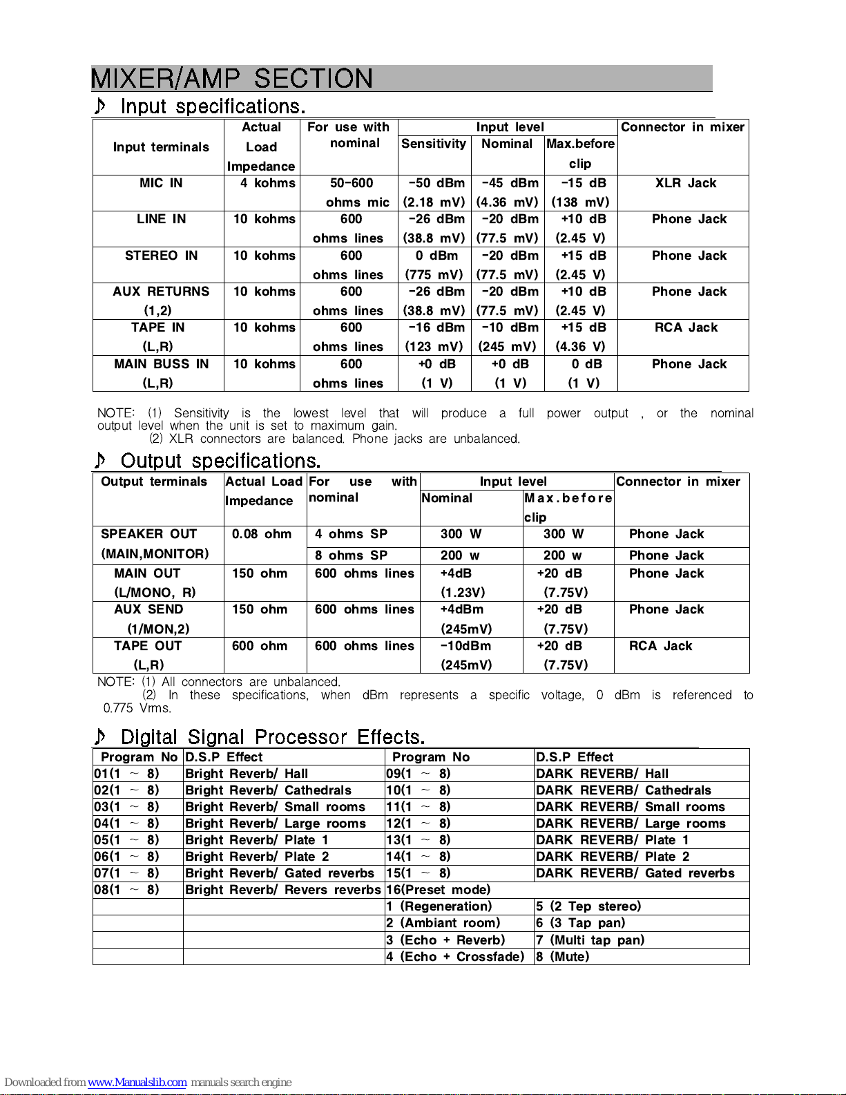
MIXER/AMP SECTION
♪
Input specifications.
Input terminals
Actual
Load
Impedance
For use with
nominal
Input level
Connector in mixer
Sensitivity
Nominal
Max.before
clip
MIC IN
4 kohms
50-600
ohms mic
-50 dBm
(2.18 mV)
-45 dBm
(4.36 mV)
-15 dB
(138 mV)
XLR Jack
LINE IN
10 kohms
600
ohms lines
-26 dBm
(38.8 mV)
-20 dBm
(77.5 mV)
+10 dB
(2.45 V)
Phone Jack
STEREO IN
10 kohms
600
ohms lines
0 dBm
(775 mV)
-20 dBm
(77.5 mV)
+15 dB
(2.45 V)
Phone Jack
AUX RETURNS
(1,2)
10 kohms
600
ohms lines
-26 dBm
(38.8 mV)
-20 dBm
(77.5 mV)
+10 dB
(2.45 V)
Phone Jack
TAPE IN
(L,R)
10 kohms
600
ohms lines
-16 dBm
(123 mV)
-10 dBm
(245 mV)
+15 dB
(4.36 V)
RCA Jack
MAIN BUSS IN
(L,R)
10 kohms
600
ohms lines
+0 dB
(1 V)
+0 dB
(1 V)
0 dB
(1 V)
Phone Jack
NOTE: (1) Sensitivity is the lowest level that will produce a full power output , or the nominal
output level when the unit is set to maximum gain.
(2) XLR connectors are balanced. Phone jacks are unbalanced.
♪
Output specifications.
Output terminals
Actual Load
Impedance
For use with
nominal
Input level
Connector in mixer
Nominal
M a x . b e f o r e
clip
SPEAKER OUT
(MAIN,MONITOR)
0.08 ohm
4 ohms SP
300 W
300 W
Phone Jack
8 ohms SP
200 w
200 w
Phone Jack
MAIN OUT
(L/MONO, R)
150 ohm
600 ohms lines
+4dB
(1.23V)
+20 dB
(7.75V)
Phone Jack
AUX SEND
(1/MON,2)
150 ohm
600 ohms lines
+4dBm
(245mV)
+20 dB
(7.75V)
Phone Jack
TAPE OUT
(L,R)
600 ohm
600 ohms lines
-10dBm
(245mV)
+20 dB
(7.75V)
RCA Jack
NOTE: (1) All connectors are unbalanced.
(2) In these specifications, when dBm represents a specific voltage, 0 dBm is referenced to
0.775 Vrms.
♪
Digital Signal Processor Effects.
Program No
D.S.P Effect
Program No
D.S.P Effect
01(1~8)
Bright Reverb/ Hall
09(1~8)
DARK REVERB/ Hall
02(1~8)
Bright Reverb/ Cathedrals
10(1~8)
DARK REVERB/ Cathedrals
03(1~8)
Bright Reverb/ Small rooms
11(1~8)
DARK REVERB/ Small rooms
04(1~8)
Bright Reverb/ Large rooms
12(1~8)
DARK REVERB/ Large rooms
05(1~8)
Bright Reverb/ Plate 1
13(1~8)
DARK REVERB/ Plate 1
06(1~8)
Bright Reverb/ Plate 2
14(1~8)
DARK REVERB/ Plate 2
07(1~8)
Bright Reverb/ Gated reverbs
15(1~8)
DARK REVERB/ Gated reverbs
08(1~8)
Bright Reverb/ Revers reverbs
16(Preset mode)
1 (Regeneration)
5 (2 Tep stereo)
2 (Ambiant room)
6 (3 Tap pan)
3 (Echo + Reverb)
7 (Multi tap pan)
4 (Echo + Crossfade)
8 (Mute)
 Loading...