

Page 1

SM-16SDDR / VM-16SDDR
VM-14SDDR
Professional Console Powered Mixer
OWNER'S MANUAL
Post or Pre Post or Pre Post or Pre Post or Pre Post or Pre Post or Pre Post or Pre Post or Pre
Delay Reverb
Delay Level
Revarb Level
Delay Time
Delay Repeat
Revarb Time
SLEEVE TIP(+)
RING(-)
SLEEVE TIP(+)
RING(-)
SLEEVE TIP(+)
RING(-)
SLEEVE TIP(+)
RING(-)
SLEEVE TIP(+)
RING(-)
SLEEVE TIP(+)
RING(-)
SLEEVE TIP(+)
RING(-)
SLEEVE
SEND
RETURN
SLEEVE
SEND
RETURN
SLEEVE
SEND
RETURN
1=GND,
3=COLD(-)
2=HOT(+)
1=GND,
3=COLD(-)
2=HOT(+)
1=GND,
3=COLD(-)
2=HOT(+)
1=GND,
3=COLD(-)
2=HOT(+)
1=GND,
3=COLD(-)
2=HOT(+)
1=GND,
3=COLD(-)
2=HOT(+)
1=GND,
3=COLD(-)
2=HOT(+)
1=GND,
3=COLD(-)
2=HOT(+)
9
13 15
14 16
101112
BAL STEREO
Input Channels
All Left Inputs = Mono
Programs
1 -
2 -
3 -
4 -
1 -
2 -
3 -
4 -
9 - 10
15-16
11-12 13-14
Digi DDR
Post
or
pre
Post
or
pre
Sends
Monitor
Digi DDR Digi DDR Digi DDR Digi DDR Digi DDR Digi DDR Digi DDR Digi DDR
MAX
D
I
G
I
U
A
U
X
U
MAX
MAX
MAX
D
I
G
I
U
A
U
X
U
MAX
MAX
MAX
D
I
G
I
U
A
U
X
U
MAX
MAX
MAX
D
I
G
I
U
A
U
X
U
MAX
MAX
MAX
D
I
G
I
U
A
U
X
U
MAX
MAX
MAX
D
I
G
I
U
A
U
X
U
MAX
MAX
MAX
D
I
G
I
U
A
U
X
U
MAX
MAX
MAX
D
I
G
I
U
A
U
X
U
MAX
MAX
MAX
D
I
G
I
U
A
U
X
U
MAX
MAX
MAX
D
I
G
I
U
A
U
X
U
MAX
MAX
4U
0U
MAX
P
R
E
U
P
O
S
T
U
MAX
P
R
E
U
P
O
S
T
U
MAX
0
U
4
U
-10dBU
-8
0
U
4
U
-10dBU
-8
4U
0U
MAX
-50dBU+1
-32dBU20dBU
-20
U
-10
U
L
i
n
e
M
i
c
-50dBU+1
-32dBU20dBU
-20
U
-10
U
L
i
n
e
M
i
c
-50dBU+1
-32dBU20dBU
-20
U
-10
U
L
i
n
e
M
i
c
-50dBU+1
-32dBU20dBU
-20
U
-10
U
L
i
n
e
M
i
c
-50dBU+1
-32dBU20dBU
-20
U
-10
U
L
i
n
e
M
i
c
-50dBU+1
-32dBU20dBU
-20
U
-10
U
L
i
n
e
M
i
c
-50dBU+1
-32dBU20dBU
-20
U
-10
U
L
i
n
e
M
i
c
-50dBU+1
-32dBU20dBU
-20
U
-10
U
L
i
n
e
M
i
c
GND TIP(+)
RING(-)
BAL=
UNBAL
Digi DDR Effect Processor
UNBAL=
GND TIP(+)
Digi DDR
Programs
Delay
Programs
1. Delay/ECHO
50~1000 msec
2. Delay CROSS F.B
50~1000 msec
3. Delay 3 Tap PAN
50~1000 msec
4. Delay One Short
50~1000 msec
Reverb
Programs
1. Reverb Hall
2~10 sec
2. Reverb Room
0.5~5 sec
3. Reverb Plate
1~8 sec
4. Reverb AMBIENT
200~2000msec
Page 2

2
SM-16SDDR / VM-16SDDR
VM-14SDDR
Professional Console Powered Mixer
Table of Contents
1.
Introduction
................................................................................................................................................................................
3
2.
Important Safety Instructions
.................................................................................................................................
4-5
3.
Warranty Information
.......................................................................................................................................................
6
4.
Connecting Your System
.............................................................................................................................................
7-10
5.
Operating Your System
.................................................................................................................................................
10-13
6.
Panel Description
..................................................................................................................................................................
14-23
7.
Troubleshooting
....................................................................................................................................................................
24
8.
Block Diagram
.........................................................................................................................................................................
25-26
9.
Specications
..........................................................................................................................................................................
27-29
10.
Rack Bracket Mounting
.................................................................................................................................................
30-31
Page 3

1.
Introduction
Congratulations and thank you for choosing a STK professional console powered mixer.
The new SM-16SDDR/VM-16SDDR/VM-14SDDR powered stereo mixing consoles are
professional quality products combining a full featured mixing console with stereo graphic
equalizers, digital signal processing and integrated stereo power amplifications. The mixer and
equalizer/amplier sections can be electronically separated allowing complete exibility in a variety
of applications. The products features oversized heat sinks along with two speed, direct air cooling
for trouble free operation under the most adverse conditions. In addition, these three kind models
have a bar graphic LED display to performance conditions. While providing powerful, accurate and
reliable performance along with outstanding value, your STK new SM-16SDDR/VM-16SDDR/
VM-14SDDR powered mixing console has been designed for many years of dependable service.
These powered mixers ideal for portable PA systems for venues and medium large live sound club,
meeting room, sanctuary, or outdoor gathering. Please take the time to read this manual before
operation so that you fully understand and correct use of this ne products.
3
Page 4

4
2.
Important Safety Instructions
1. Read Instructions
All the safety and operating instructions should be read before the appliance is operated.
2. Retain Instructions
The safety and operating instructions should be retained for future reference.
3. Heed Warnings
All warnings on this appliance and in the operating instructions should be adhered to.
4. Follow Instructions
All instructions should be followed.
5. Water and Moisture
This appliance should not be used near water- for example, near a bathtub, sink, laundry tub, in a wet basement, near a swimming
pool, etc.
6. Heat
This appliance should be situated away from heat sources such as radiators, heat registers, stoves, or other appliances (including
ampliers) that produce heat.
7. Power Sources
This appliance should be connected to a power supply only of the type described in the operating instructions or as marked on the
appliance. If you are not sure of the type of power supply to your home, consult your appliance dealer or local power company.
For appliances intended to operate from battery power, or other sources, refer to the operating instructions.
8. Polarization
If the appliance is equipped with a polarized alternating-current line plug (a plug having one blade wider than the other), this plug
will t into the power outlet only one way. This is a safety feature. If you are unable to insert the plug fully into the outlet, try
reversing the plug. If the plug should still fail to t, contact your electrician to replace your obsolete outlet. Do not defeat the safety
purpose of the polarized plug.
9. Grounding
If the appliance is equipped with a 3-wire grounding-type plug, a plug having a third (grounding) pin, this plug will only t into a
grounding-type power outlet. This is safety feature. If you are unable to insert the plug into the outlet, contact your electrician to
replace your obsolete outlet. Do not defeat the safety purpose of the grounding-type plug.
10. Power Cord Protection
Power supply cords should be routed so that they are not likely to be walked on or pinched by items placed upon or against them,
paying particular attention to cords at plugs, convenience receptacles, and the point where they exit from the appliance.
11. Damage Requiring Service
Unplug this appliance from the wall outlet and refer servicing to qualied service personnel under the following conditions:
a. When the power-supply cord or plug is damaged.
b. If liquid has been spilled, or objects have fallen into the appliance.
c. If the appliance has been exposed to rain or water.
d. If the appliance does not operate normally by following the operating Instructions. Adjust only those controls that are
covered by the operating instructions as an improper adjustment of other controls may result in damage and will often require
extensive work by a qualied technician to restore the appliance to its normal operation.
e. If the appliance has been dropped or the cabinet has been damaged.
f. When the appliance exhibits a distinct change in performance-this indicates a need for service.
12. Servicing
Do not attempt to service this appliance yourself as opening or removing covers may expose you to dangerous voltage or other
hazards. Refer all servicing to qualied service personnel.
Page 5

2.
Important Safety Instructions
5
Some common decibel ranges :
Level Example
30 Quiet library, Soft whispers
40 Living room, Refrigerator, Bedroom away from trafc
50 Light trafc, Normal ConversationAir
60 Conditioner at 20 ft., Sewing machine
70 Vacuum cleaner, Hair dryer, Noisy Restaurant
80 Average city trafc, Garbage disposals, Alarm clock at 2 ft.
13. Listening for a Lifetime
Selecting ne audio equipment such as the unit you've just purchased is only the start of your musical enjoyment. Now it's time
to consider how you can maximize the fun and excitement your equipment offers. STK PROFESSIONAL and the Electronic
Industries Association's Consumer Electronics Group want you to get the most out of your equipment by playing it at a safe level.
One that lets the sound come through loud and clear without annoying blaring or distortion and, most importantly, without
affecting your sensitive hearing.
Sound can be deceiving. Over time your hearing “comfort level” adapts to a higher volume of sound. So what sounds “normal”
can actually be loud and harmful to your hearing. Guard against this by setting your equipment at a safe level BEFORE your
hearing adapts.
To establish a safe level :
•
Start your volume control at a low setting.
•
Slowly increase the sound until you can hear it comfortably and clearly, and without distortion.
Once you have established a comfortable sound level :
•
Set the dial and leave it there.
•
Pay attention to the different levels in various recordings.
Taking a minute to do this now will help to prevent hearing damage or loss in the future. After all, we want you listening for a
lifetime.
Used wisely, your new sound equipment will provide a lifetime of fun and enjoyment. Since hearing damage from loud noise is
often undetectable until it is too late, this manufacturer and the Electronic Industries Association's Consumer Electronics Group
recommend you avoid prolonged exposure to excessive noise. This list of sound levels is included for your protection.
Page 6

6
UNPACKING
As a part of our system of quality control, every STK
product is carefully inspected before leaving the factory
to insure awless appearance.
After unpacking, please inspect for any physical
damage. Save the shipping carton and all packing
materials, as they were carefully designed to reduce the
possibility of transportation damage should the unit
again require packing and shipping.
In the event that damage has occurred, immediately
notify your dealer so that a written claim to cover the
damage can be initiated with the carrier. The right to
any claim against a public carrier can be forfeited if
the carrier is not promptly notied and if the shipping
carton and packing materials are not available for
inspection by the carrier. Save all packing materials until
the claim has been settled.
STK Customer Service Department
396-43, CHEONGCHEON-DONG, BUPYEONG-GU,
INCHEON, KOREA.
TEL : +82-(0)32-525-1788~1790
FAX : +82-(0)32-525-1784
E-mail : stkcom@stkpro.com
www.stkpro.com
STK LIMITED 1 YEAR WARRANTY
STK electronics are warranted to be free from defects
in materials and workmanship under normal use for a
period of 1 year from date of original purchase.
During that period, STK will at its option, repair
or replace materials at no charge if product has been
delivered to STK by a STK dealer or STK Service Center
together with the original sales receipt or other proof of
purchase.
Warranty excludes fuses, exterior nish, normal wear,
failure due to abuse, or operation outside of specified
ratings. Warranty applies to original purchaser only.
This warranty gives you specic legal rights which vary
from state to state.
For more information about warranty repair,
please contact : Customer Service Dept., The STK
Professional Audio.
FOR YOUR RECORDS
All of us at STK thank you for your expression
of confidence in STK products. The unit you have
purchased is protected by a limited 1 year warranty. To
establish the warranty, be sure to fill out and mail the
warranty card attached to your product.
For you own protection, ll out the information below for you own records.
Other Information :
3.
Warranty Information
Model Number :
Dealer :
Phone :
Serial Number :
Date Of Purchase :
Salesman :
Page 7

7
On Off
VS-15
STEREO DIGITAL POWER AMPLIFIER
BRIDGE
Post or Pre Post or Pre Post or Pre Post or Pre Post or Pre Post or Pre Post or Pre Post or Pre
Delay Reverb
Delay Level
Revarb Level
Delay Time
Delay Repeat
Revarb Time
SLEEVE TIP(+)
RING(-)
SLEEVE TIP(+)
RING(-)
SLEEVE TIP(+)
RING(-)
SLEEVE TIP(+)
RING(-)
SLEEVE TIP(+)
RING(-)
SLEEVE TIP(+)
RING(-)
SLEEVE TIP(+)
RING(-)
SLEEVE
SEND
RETURN
SLEEVE
SEND
RETURN
SLEEVE
SEND
RETURN
1=GND,
3=COLD(-)
2=HOT(+) 1=GND,
3=COLD(-)
2=HOT(+) 1=GND,
3=COLD(-)
2=HOT(+) 1=GND,
3=COLD(-)
2=HOT(+) 1=GND,
3=COLD(-)
2=HOT(+) 1=GND,
3=COLD(-)
2=HOT(+) 1=GND,
3=COLD(-)
2=HOT(+) 1=GND,
3=COLD(-)
2=HOT(+)
9
13 15
14 16
101112
BAL STEREO
Input Channels
All Left Inputs = Mono
Programs
1 -
2 -
3 -
4 -
1 -
2 -
3 -
4 -
9 - 10
15-16
11-12 13-14
Digi DDR
Post
or
pre
Post
or
pre
Sends
Monitor
Digi DDR Digi DDR Digi DDR Digi DDR Digi DDR Digi DDR Digi DDR Digi DDR
MAX
D
I
G
I
U
A
U
X
U
MAX
MAX
MAX
D
I
G
I
U
A
U
X
U
MAX
MAX
MAX
D
I
G
I
U
A
U
X
U
MAX
MAX
MAX
D
I
G
I
U
A
U
X
U
MAX
MAX
MAX
D
I
G
I
U
A
U
X
U
MAX
MAX
MAX
D
I
G
I
U
A
U
X
U
MAX
MAX
MAX
D
I
G
I
U
A
U
X
U
MAX
MAX
MAX
D
I
G
I
U
A
U
X
U
MAX
MAX
MAX
D
I
G
I
U
A
U
X
U
MAX
MAX
MAX
D
I
G
I
U
A
U
X
U
MAX
MAX
4U
0U
MAX
P
R
E
U
P
O
S
T
U
MAX
P
R
E
U
P
O
S
T
U
MAX
0
U
4
U
-10dBU
-8
0
U
4
U
-10dBU
-8
4U
0U
MAX
-50dBU+1
-32dBU20dBU
-20
U
-10
U
L
i
n
e
M
i
c
-50dBU+1
-32dBU20dBU
-20
U
-10
U
L
i
n
e
M
i
c
-50dBU+1
-32dBU20dBU
-20
U
-10
U
L
i
n
e
M
i
c
-50dBU+1
-32dBU20dBU
-20
U
-10
U
L
i
n
e
M
i
c
-50dBU+1
-32dBU20dBU
-20
U
-10
U
L
i
n
e
M
i
c
-50dBU+1
-32dBU20dBU
-20
U
-10
U
L
i
n
e
M
i
c
-50dBU+1
-32dBU20dBU
-20
U
-10
U
L
i
n
e
M
i
c
-50dBU+1
-32dBU20dBU
-20
U
-10
U
L
i
n
e
M
i
c
GND TIP(+)
RING(-)
BAL=
UNBAL
Digi DDR Effect Processor
UNBAL=
GND TIP(+)
Digi DDR
Programs
Delay
Programs
1. Delay/ECHO
50~1000 msec
2. Delay CROSS F.B
50~1000 msec
3. Delay 3 Tap PAN
50~1000 msec
4. Delay One Short
50~1000 msec
Reverb
Programs
1. Reverb Hall
2~10 sec
2. Reverb Room
0.5~5 sec
3. Reverb Plate
1~8 sec
4. Reverb AMBIENT
200~2000msec
SM-16SDDR
FOR CLUB
VFX-299
SP-112M
V-3.5M
SP-118SL SP-118SL
VS-15
SP-112M
DI-2000A
Professional
Console
Powered Mixer
Right/Monitor
Speaker Outputs
2+
2
1+
1
NC
NC
Left/Main
Speaker Outputs
2+
2
1+
1
NC
NC
SP-152HSP-152H SP-152HSP-152H
Main Speaker System Main Speaker System
Rear Panel
Front Panel
DI-Box
Keyboard
Recorder
Cd Player
Mic
Effects Processor
Monitor Monitor
Monitor Amplifier
Subwoofer Amplifier
Subwoofer Speaker
Guitar
A. System Hookups
Note : The Connecting of the SM-16SDDR/VM-16SDDR/VM-14SDDR console powered mixer is nearly identical, this system
hookups will help you to understand and get the most out of all these 3 kind powered mixers. Before you begin your connections,
you must decide how you will congure your sound system, mono or stereo. Below are system variations that can be used with
your powered mixer. Carefully consider all of them to decide which system you will use.
Note : The SM-16SDDR console powered Mixers feature exible patching options which make possible more variations of setup
than are presented here. Once familiarized with the unit's capabilities, you should be able to achieve practically any setup you
desire.
1. Powered Stereo With Sub Woofer System Hook Diagram
SM-16SDDR Powered Stereo With Sub Woofer System : Set the Amp Assign switch to the stereo (out) position.
The basic stereo with sub woofer setup: One or more parallel speaker systems connected to each of the left and right sides of
the output operating in stereo. And connect the sub woofer output jack on the front panel directly to the input jack of your sub
woofer power amplier. : Addition of an externally powered monitor system.(See following Hookup diagram)
4.
Connecting Your System
Page 8

8
4.
Connecting Your System
2. Powered Main+Monitors System Hookup Diagrams
VM-16SDDR Powered Main(L+R) + Monitor system : Set the Amp Assign switch to the L+R/Monitor (in) position.
Now that you have decided which mode and type of system operation you will use, The basic Main(L+R)+Monitor setup : One or
more parallel speaker systems connected to the left side for Main, and one or more parallel speaker systems connected to the right
side for Monitor system.(See following Hookup diagram)
On O
Post or Pre Post or Pre Post or Pre Post or Pre Post or Pre Post or Pre Post or Pre Post or Pre
Delay Reverb
Delay Level
Revarb Level
Delay Time
Delay Repeat
Revarb Time
V
SLEEVE TIP(+)
RING(-)
SLEEVE TIP(+)
RING(-)
SLEEVE TIP(+)
RING(-)
SLEEVE TIP(+)
RING(-)
SLEEVE TIP(+)
RING(-)
SLEEVE TIP(+)
RING(-)
SLEEVE TIP(+)
RING(-)
SLEEVE
SEND
RETURN
SLEEVE
SEND
RETURN
SLEEVE
SEND
RETURN
1=GND,
3=COLD(-)
2=HOT(+) 1=GND,
3=COLD(-)
2=HOT(+) 1=GND,
3=COLD(-)
2=HOT(+) 1=GND,
3=COLD(-)
2=HOT(+) 1=GND,
3=COLD(-)
2=HOT(+) 1=GND,
3=COLD(-)
2=HOT(+) 1=GND,
3=COLD(-)
2=HOT(+) 1=GND,
3=COLD(-)
2=HOT(+)
9
13 15
14 16
101112
BAL STEREO
Input Channels
All Left Inputs = Mono
Programs
1 -
2 -
3 -
4 -
1 -
2 -
3 -
4 -
9 - 10
15-16
11-12 13-14
Digi DDR
Post
or
pre
Post
or
pre
Sends
Monitor
Digi DDR Digi DDR Digi DDR Digi DDR Digi DDR Digi DDR Digi DDR Digi DDR
MAX
D
I
G
I
U
A
U
X
U
MAX
MAX
MAX
D
I
G
I
U
A
U
X
U
MAX
MAX
MAX
D
I
G
I
U
A
U
X
U
MAX
MAX
MAX
D
I
G
I
U
A
U
X
U
MAX
MAX
MAX
D
I
G
I
U
A
U
X
U
MAX
MAX
MAX
D
I
G
I
U
A
U
X
U
MAX
MAX
MAX
D
I
G
I
U
A
U
X
U
MAX
MAX
MAX
D
I
G
I
U
A
U
X
U
MAX
MAX
MAX
D
I
G
I
U
A
U
X
U
MAX
MAX
MAX
D
I
G
I
U
A
U
X
U
MAX
MAX
4U
0U
MAX
P
R
E
U
P
O
S
T
U
MAX
P
R
E
U
P
O
S
T
U
MAX
0
U
4
U
-10dBU
-8
0
U
4
U
-10dBU
-8
4U
0U
MAX
-50dBU+1
-32dBU20dBU
-20
U
-10
U
L
i
n
e
M
i
c
-50dBU+1
-32dBU20dBU
-20
U
-10
U
L
i
n
e
M
i
c
-50dBU+1
-32dBU20dBU
-20
U
-10
U
L
i
n
e
M
i
c
-50dBU+1
-32dBU20dBU
-20
U
-10
U
L
i
n
e
M
i
c
-50dBU+1
-32dBU20dBU
-20
U
-10
U
L
i
n
e
M
i
c
-50dBU+1
-32dBU20dBU
-20
U
-10
U
L
i
n
e
M
i
c
-50dBU+1
-32dBU20dBU
-20
U
-10
U
L
i
n
e
M
i
c
-50dBU+1
-32dBU20dBU
-20
U
-10
U
L
i
n
e
M
i
c
GND TIP(+)
RING(-)
BAL=
UNBAL
Digi DDR Eect Processor
UNBAL=
GND TIP(+)
Digi DDR
Programs
Delay
Programs
1. Delay/ECHO
50~1000 msec
2. Delay CROSS F.B
50~1000 msec
3. Delay 3 Tap PAN
50~1000 msec
4. Delay One Short
50~1000 msec
Reverb
Programs
1. Reverb Hall
2~10 sec
2. Reverb Room
0.5~5 sec
3. Reverb Plate
1~8 sec
4. Reverb AMBIENT
200~2000msec
Professional Console Powered Mixer
VM-16SDDR
FOR HOUSE OF WORSHIP
DI-Box
Keyboard
VFX-299
DI-2000A
Recorder
Cd Player
Mic
Effects Processor
Right/Monitor
Speaker Outputs
2+
2
1+
1
NC
NC
Left/Main
Speaker Outputs
2+
2
1+
1
NC
NC
Main Speaker System (L+R) Main Speaker System (L+R)
Rear Panel
SP-115M
SP-153H SP-153H
SP-115M
Monitor Monitor
Guitar
Page 9
9
Ⅰ
Introduction l
제품 소개
B. CONNECTORS
Your SM-16SDDR/VM-16SDDR/VM-14SDDR professional console powered mixers uses several types of input and output
connectors.
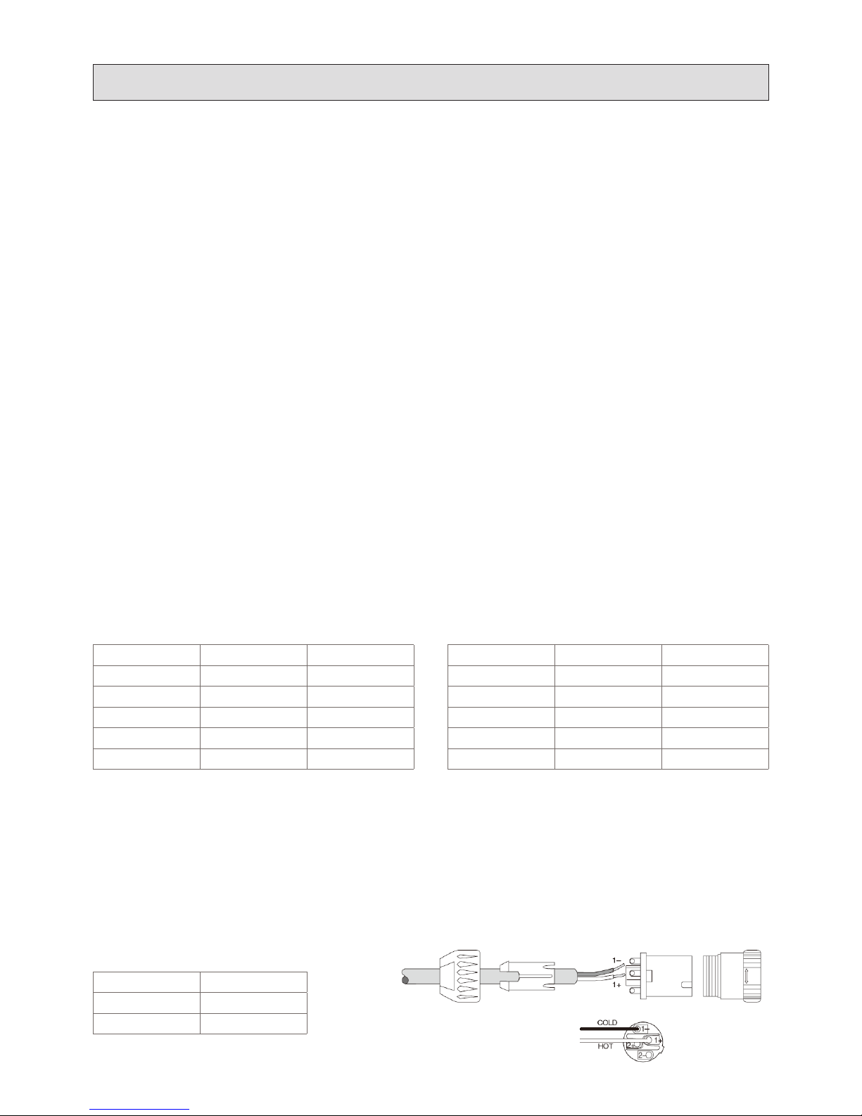
1. XLR Input jacks
Electronically balanced inputs accept a standard XLR male connector. Pin1=ground, pin2=hot or positive(+) and pin3=cold
or negative (-) (see Figure a). These connectors should be utilized for low impedance microphones. If you are using a high
impedances microphone, it will likely have a cord with a 1/4 connector on it. In this case, it would be appropriate to plug such
microphones into a line input, however performance, and gain may be lessened. for best performance. We recommend you invest
in one of the many higher quality, law impedance mics available on the market, or alternatively, purchase an impedance matching
transformer from your dealer.
2. TS 1/4″Phone Input Jacks
These tip / sleeve(TS) jacks accept an unbalanced line level signal using a normal male phone plug. (See Figure b)
TS Jacks and plugs are used in many different applications, always unbalanced. The tip(+) is connected to the audio signal and the
sleeve to ground (earth).
3. TRS 1/4″ Phone Stereo Jacks
The 1/4″phone stereo jacks are 1/4″three conductor jacks. 1/4″Tip is send (or hot) Ring is return(or cold) and sleeve is
ground(TRS).
The 1/4” stereo Jacks can be used a channel insert jacks : post-gain, and pre-EQ or stereo channel balanced inputs: tip is hot(+)
ring is cold(-) sleeve is ground. (See Figure c)
4. Speaker Output Jacks
The speaker output jacks are 1/4″two conductor jacks. Their power output and function are dependent upon the particular unit
that you are using. (See Figure d)
The tip is connected to the speaker-level audio signal positive and sleeve to negative not ground (earth).
Use speaker cables with a minimum conductor size for the length you need as listed in below.
4.
Connecting Your System
For cable lengths over 60m(200ft) at 8 ohms, and over 30m(100ft) at 4 ohms, the conductor sizes needed for less than 0.5dB
power losses are rarely practical for physical and cost reasons. As a practical compromise for these situations the recommended
conductor gauge is 10AWG or 25 metric.
The Speakons, Speakon connectors are purpose-built for low voltage, high current applications.
Each connector incorporates two pair of conductors, labeled 1+, 1-, by convention, single.
When attaching NL4FC mating connectors, be sure to insert the connector to its full depth, then turn the connector
45°clockwise to lock it in place. wire the speakon connectors as shown below.
•
Connection Table
Minimum AWG 4 Ohm 8 Ohm
18 3m(10ft) 7.6m(25ft)
16 7.6m(25ft) 15m(50ft)
14 7.6m(25ft) 23m(75ft)
12 15m(50ft) 38m(125ft)
10 30m(100ft) 60m(200ft)
Output Function Pins
Left 1+, 1-
Right 1+, 1-
Min Metric WG 4 Ohm 8 Ohm
12 3m(10ft) 8m(26ft)
14 8m(26ft) 15m(50ft)
16 8m(26ft) 25m(82ft)
20 15m(50ft) 40m(131ft)
25 30m(100ft) 60m(200ft)
Page 10

4.
Connecting Your System
For Powered Stereo with Sub Woofer System Hook Diagram.
A. Connections
1.Power Switch OFF
Be sure the rear panel power switch is off before making any connections.
2. Connect the mains power
Push the line cord securely into the IEC connector on the rear panel, connect it to an AC outlet.
3. Connect the input devices into the one or more input channels.
Plug a balanced microphone into one of the mic XLR connectors on the front panel. Or other line level signal source(key board
or guitar DI box) into one of the 1/4” line input phone jacks.
4. Connect the input devices into the Stereo input channels 7-8(VM-14SDDR)/9-10(SM,VM-16SDDR) and more stereo
channels :
Using standard 1/4″shielded cables, connect the desired devices into the stereo input channels:
Keyboards, drum machines, tape programs and others.
5. Connect the tape and CD player
If you are feeding a signal from a tape or CD player into your power mixer, using a stereo RCA cable, Connect the output jacks
of the player to the tape in jacks on the front panel. If you wish to record the output of your power mixer, using a stereo RCA
cable, connect the tape out jack on the front panel to the input jacks of the CD or tape recorder.
10
5.
Operating Your System
4. RCA Phone Jacks
The RCA jacks accept unbalanced male pin connectors. (See Figure e)
The tip is connected to the audio signal and the sleeve to ground (earth).
a. Female 3 Pin XLR Connector
d. Speaker Jack
b. Unbalanced 1/4'' Connector
e. RCA Jack
c. Balanced 1/4'' Stereo Connector
Tip
Sleeve
Ring
POSITIVE(+)
NEGATIVE(-)
Page 11

11
5.
Operating Your System
6. Connect the external effects device
If you are utilizing an external effects device, using standard 1/4″shielded cables, connect the Aux send jack on the top of front
panel to the input jack of the effects device and connect the output jack of the effects device to the stereo input channels (VM14SDDR :11-12 or 13-14/SM,VM-16SDDR : 13-14 or 15-16) inputs jack on the front panel.
7. Connect the passive speakers
Using heavy gauge(more than 18 gauge) unshielded 1/4″speaker cables or speakon jack cables, connect your left and right main
speaker systems to the each side of two parallel speaker output jacks on the rear panel. The total speaker impedance load of
your speaker systems connected must be 4 ohms or greater. If you plug two speakers parallel, each speakers must be 8 ohms or
greater. Don’t use guitar cords for speaker cables it will be too hot. If you are not certain of your total speaker impedance load,
contact your dealer for assistance.
WARNING: Operating your SM-16SDDR/VM-16SDDR/VM-14SDDR powered mixer at an output impedance less than 4
ohms, and then can damage your unit and void your warranty!
8. Connect the subwoofer system (Optional)
If you are utilizing a separate subwoofer system, using a standard 1/4" shielded cable, connect the subwoofer jack to the
Input jack of the your subwoofer Amplier; using a heavy gauge unshielded 1/4" speaker cable, connect the subwoofer to the
subwoofer Amplier output jack.
9. Connect the external Monitor Equalizer
If you are utilizing an external graphic equalizer for the monitors, using a standard 1/4″shielded cable, Connect the monitor out
jack on the front panel to the input jack of your external monitor equalizer.
10. Connect your external Monitor Power Amp
If you are utilizing an external equalizer for the monitors, using a XLR cable or a standard 1/4″shielded cable, connect the
output jack of your monitor equalizer to the input jack of your monitor power amp.
If you are not using an external monitor equalizer, connect the monitor out jack on the front panel directly to the input jack of
your monitor power amplier.
11. Connect the Monitor speakers
Using heavy gauge unshielded 1/4″speaker cables, connect your monitor speakers to the output jacks of the monitor power
amplier. make sure that the total impedance load of your monitor speakers is not less than the recommended minimum
impedance that your monitor power amp can safely handle.
B. Ready, steady, Getting sound!
1.
The channel level fader, monitor, and EFX/DSP controls fully down.
2.
Set all the EQ controls to the center, including the graphic EQ sliders.
3.
Slide down the main level and main monitor fader, and Amp In Level controls fully down.
4.
For each mono channel, the gain control knobs turn to the around AM 10:00 Counterclockwise(line unity gain)position if you
are using a line-level source. Turn to the around PM 13:30 clockwise(mic unity gain) if you are using a microphone or other
low-level source.
5.
For condenser mics, turn on the phantom power switch on the rear panel. If you are using both condenser and dynamics, don’t
worry. Phantom power will not hurt most dynamics. Check the microphone user manual if you are not sure.
6.
For each stereo channel, press out the level switch (low gain) if you are using a line-level source. Press in the level switch(high
gain) if you are using other low-level source.
7.
Play something into the selected input and sliding up the channel level fader to -5 or U(unity). This could be an instrument, a
singing or speaking voice, or a line input such as a CD player or tape recorder output. Be sure that the volume of the input source
is the same as it would be during normal use. If it isn't, you might have to readjust these levels during the middle of the set.
8.
The amp in level controls turn to 5 or more but not to max(about 70%) then slowly sliding up the main(L/R) level control
fader, and main monitor level control fader(if you decided Powered Main+Monitors system) until you hear the signal in your
speakers. The Amp In Level controls just before internal power amp input circuit and it is similar to your external power amp
volume control knobs. you will likely have to re-adjust this later, but for now, this setting will allow you to hear your powered
stereo system and decide what further adjustments are necessary.
9.
Repeat steps 4 to 7 for the remaining channels.
10.
Adjust the levels to get the best mix. Keep the level controls fully down on unused channels.
Page 12

5.
Operating Your System
C. Graphic Equalizer use
The SM-16SDDR/VM-16SDDR/VM-14SDDR is equipped with a dual 5-band equalizer that can be congured to affect master
output and each main speaker output. You should think of the graphic equalizer as an extended "Tone Control." the built-in
graphic equalizer(s) divide the audio spectrum into 5 segments or bands. You can raise or lower the level of each individual band
by adjusting the slider on that band. Any environment has its own set of acoustics, even outdoors. Some environments will reect
or absorb certain frequencies more than others. a graphic equalizer allows you to attenuate ranges of frequencies that are too
strong and boost others that are too weak, or, in other words, to "Equalize" the ve different bands in their relationship to each
other.
1. Set all of the 5 EQ sliders at 0(middle)position, where there is a detent.
2. Adjust the Equalizer. Try to adjust the Graphic Equalizer until the system sounds the way you think it should. Try to ascertain
which areas of the audio spectrum are too strong and which are too weak. Adjust the Graphic Equalizer to compensate for these
differences. Make further adjustments to the Graphic Equalizer to compensate for any feedback problems that may exist. See the
Professional Operating Tips section of this manual for more detailed instructions on this procedure.
D. Protection Circuit
The STK console powered mixer is designed full circuit protection and have protect indicator LED(red) on the front panel. The
protect LED indicates that there is a problem either in the amplier's external connections, load or temperature conditions or its
internal functions. If one of these situations occurs, the amplier senses the problem and automatically switches into its "Protect
Mode". The LED will light to warn you of the trouble and the amplier will stop working. If the LED lights and stays on, switch
the unit off. If you feel that you have been able to correct the fault condition that caused the unit to go into the protect mode,
switch the powered mixer on again. If you have successfully removed the fault condition, the amplier will run normally.
CAUTION
: If the protect LED remains lit when attempting to resume operation, DO NOT USE THE UNIT. Take your STK
console powered mixers to an authorized service facility or contact your dealer for help.
E. MONITOR OPERATION
The idea behind a monitor system is to provide a completely independent mix of your input signals to your monitor speakers so
that the performers can hear what they are doing and perform their best.
Because of speaker placement, program material, and several other factors, it is rare that the monitor mix will be the same as the
main mix.
1. Set the Master Main Mix Level Fader Control to Zero
Since the monitor mix is completely separate from the main mix, all of the monitor settings will be initially made with the master
level control set to the zero position.
2. Set the Master Monitor Send Level Fader Control to Zero
3. Set the input Level of the External Monitor Equalizer(if applicable)
If you are using a separately powered monitor system, set the input level control of the equalizer to about 60%. you will need to
check this setting later to be sure there is no clipping or distortion.
4. Set External Monitor Amplifier(if applicable)
If you are using a separately powered monitor system, set the input level control of the external amplier to about 60%. You will
need to check this setting later to be sure there is no clipping or distortion.
5. Set the master Monitor send Level Control
Set the master monitor send fader control to 8 or 9(near line level out) on the front panel. You will likely have to re-adjust this
later, but for now, this setting will allow you to hear your monitor system and decide what further adjustments are necessary.
6. Set the channel Monitor Controls
Decide which channels you want to include in the monitor mix. set a nominal level on each of these channels using the channel
monitor control. Slowly raise the level on each individual channel until the optimum volume is achieved or, in the case of a
12
Page 13

microphone channel until you begin to hear feedback.
If you start to hear feedback, quickly reduce the monitor control of that channel back to 0 or until the feedback stops. Carefully
raise the control again, stopping before the point at which you experienced feedback.
7. Adjust the Monitor Equalizer
Make any adjustments necessary if you are utilizing an external graphic equalizer for the monitors , you will adjust the external
monitor equalizer.
8. Make final adjustments to the monitor system
After you have properly set the graphic equalizer, Make any further adjustments to the monitor system that are necessary. When
you have completed all adjustments to the monitor system, you can raise the level of the master main mix level fader control for
the main system.
F. CARE AND MAINTENANCE
Your STK console powered mixer is built to provide years of dependable service under demanding circumstances. It requires no
internal maintenance but a common sense approach to its use will help you enjoy long and reliable operation. Here are some tips:
1. Power Requirements
Your powered mixer is capable of 110-120V AC or 220-240V AC operation allowing world-wide usage. It is pre-wired at the
factory for the correct voltage in your country. It is possible to change the mains voltage but it is an internal operation that can
only be performed by an experienced technician. Contact your dealer or service center for more information.
2. Periodic Cleaning
Keep the unit clean by wiping frequently with a damp, soft cloth. Use a mild detergent cleaner if necessary, Applied to the cloth,
but not directly to the mixer. Do not use solvents or the other chemicals to clean the unit. A large (dry) paint brush is useful to
remove cumulated dust from between the many control knobs on the mixer. If you accidentally spill liquid onto or into the unit,
disconnect the power cord and allow the unit to dry thoroughly before attempting to use it.
3. Connecting Cables
Use only high quality connecting cables with your STK console powered mixer. Faulty or suspicious cables should be replaced to
avoid possible deterioration of your sound quality.
4. Connections
Check cable connections frequently, if you move your equipment often, check input and output jack condition to be sure they
have not sustained any transportation damage, in temporary installations, such as live performances, check all cable connections
before each performance In permanent installations, verify the operation of all cables and connections often. It is much easier to
dead with a poor cable or connection before a performance or recording session than during it.
Other Notes
•
When shutting down, turn off any external ampliers or powered speakers rst. When powering up, turn on any external
ampliers or power speakers last.
•
This SM-16SDDR/VM-16SDDR/VM-14SDDR has been inspected and tested prior to being shipped. During unpacking,
carefully check that you have received all the required accessory. this is also the time to check the main unit for damage. If
any damage is noticed , promptly report this to your shipping carrier. Save the shipping boxes and all packing materials in
case the unit needs to shipped for service.
13
5.
Operating Your System
Page 14

14
6.
Panel Descriptions
1. Mic Inputs
The microphone input to each channel strip is made through
a standard 3-pin female Mic connector, XLR(3-pin)balanced
input accepts microphone-level signal, XLR pin 1 is "Shield",
pin 2 is "Hot" and Pin 3 is "Cold". The mic input will handle
any kind of mic level you can toss at them, without over
loading.
2. Line Inputs
The Line In connection for each channel strip is located just
under MIC connector, and is made through a ¼" TRS (TipRing-Sleeve) phone jack. ¼" connector tip is "Hot" ring
"Cold" and sleeve is "Shield". Plugging a guitar into a line
input can result in the loss of high frequencies, causing an
unnatural and dull sound. Normally, you must use a STK
direct box between a guitar and a mixer's input, which serves
to convert the impedance of the guitar from high to low.
2a. Channel Insert Jack
Allows interface to external signal processing devices, or
direct channel output. 1/4" connector Tip is Send, Ring is
Return and Sleeve is Ground.
This patch point allows you to insert a compressor, equalizer
or any other signal processing device into 5.6.7.8(VM14SDDR : CH5.6) input channel strips of VM,SM-16SDDR.
3. Low Cut Switch
75Hz 18dB/octave low-cut lter eliminates unwanted
subsonic frequencies, while still allowing full use of the Low
Equalization(8). We recommend that you use the Low Cut
lter on every microphone except bass application sound
(drum, bass guitar, recording of thunder-volt)
4. Line Trim/Mic Gain
Simultaneously adjusts the mic input gain to accept signals
from -10dBu to -50dBu, and trims the line input to accept
signals from +10dBu to -40dBu. Before start input level
setting, Please read “set the level” as followings.
Set the Levels :
To set the channel GAIN controls, it's not even necessary
to hear what you're doing at the outputs of the mixer. If you
want to listen while you work, plug headphones into the
PHONES jack on the front panel, then set the PHONES
knob about one-quarter of the way up. The following steps
must be performed one channel at a time.
1. Push in the channel's SOLO (14) switch. Make sure the
SOLO MODE (21) switch is down (PFL).
2. Play something into the selected input. This could be
an instrument, a singing or speaking voice, or a line input
such as a CD player or tape recorder output. Be sure that
the volume of the input source be an instrument, a singing
or peaking voice, or a line input such as a CD player or
tape recorder output. Be sure that the volume of the input
source is the same as it would be during normal use. If it
FRONT PANEL SECTION
A. Monaural Input Channel
Note: The operation of the SM-16SDDR/VM-16SDDR/
VM-14SDDR console powered mixer is nearly identical. This
manual will help you to understand and get the most out of
all STK console powered mixers.
Post or Pre Post or Pre Post or Pre Post or Pre Post or Pre
Post or Pre
SLEEVE TIP(+)
RING(-)
SLEEVE TIP(+)
RING(-)
SLEEVE TIP(+)
RING(-)
SLEEVE TIP(+)
RING(-)
SLEEVE
TIP(+)
RING(-)
SLEEVE TIP(+)
RING(-)
SLEEVE
SEND
RETURN
SLEEVE
SEND
RETURN
1=GND,
3=COLD(-)
2=HOT(+)
1=GND,
3=COLD(-)
2=HOT(+)
1=GND,
3=COLD(-)
2=HOT(+)
1=GND,
3=COLD(-)
2=HOT(+)
1=GND,
3=COLD(-)
2=HOT(+)
1=GND,
3=COLD(-)
2=HOT(+)
Digi DDR Digi DDR Digi DDR Digi DDR Digi DDR
Digi DDR
MAX
D
I
G
I
U
A
U
X
U
MAX
MAX
MAX
D
I
G
I
U
A
U
X
U
MAX
MAX
MAX
D
I
G
I
U
A
U
X
U
MAX
MAX
MAX
D
I
G
I
U
A
U
X
U
MAX
MAX
MAX
D
I
G
I
U
A
U
X
U
MAX
MAX
MAX
D
I
G
I
U
A
U
X
U
MAX
MAX
D
I
G
I
U
A
U
X
U
-50dBU+1
-32dBU20dBU
-20
U
-10
U
L
i
n
e
M
i
c
-50dBU+1
-32dBU20dBU
-20
U
-10
U
L
i
n
e
M
i
c
-50dBU+1
-32dBU20dBU
-20
U
-10
U
L
i
n
e
M
i
c
-50dBU+1
-32dBU20dBU
-20
U
-10
U
L
i
n
e
M
i
c
-50dBU+1
-32dBU20dBU
-20
U
-10
U
L
i
n
e
M
i
c
-50dBU+1
-32dBU20dBU
-20
U
-10
U
L
i
n
e
M
i
c
U
L
i
n
e
M
i
c
1
2
3
4
5
6
7
8
9
10
11
12
2a
6a
6b
13
14
15
Page 15

15
6.
Panel Descriptions
isn't, you might have to readjust these levels during the
middle of the set.
3. Adjust the channel's GAIN(4) control so that the LEDs
on the RIGHT meter (16) stay around "0" and never go
higher than "+10."
5. High Equalization
This control gives you up to 15 dB boost or cut at 12kHz,
and it is also at at the center detent. Use it to add sizzle to
cymbals, and an overall sense of transparency or edge to the
keyboards, vocals, guitar, and bacon frying. Turn it down a
little to reduce sibilance, or to hide tape hiss.
6. Mid Equalization: Level
Provides ±12dB of Cut/Boost to the midrange frequency
signals. The frequency range affected depends on the setting
of the mid EQ frequency control (7). . MID range EQ is
often thought of as the most dynamic because the frequencies
that dene any frequencies particular sound are almost
always found in this range. The mid EQ range(100Hz to
8kHz)includes the male or female vocal range as well as the
fundamentals and harmonics for many instruments.
6a. HI Mid Equalization: Level
The high MID EQ section is a peaking/dipping equalizer
with a xed center frequency of 3KHz. Provides ±12dB of
cut or boost centered. The high MID EQ range includes
the female vocal range as well as the fundamentals and
harmonics for many instruments.
6b. LOW Mid Equalization: Level
The low MID EQ section is a peaking/dipping equalizer
with a xed center frequency of 800Hz. Provides ±12dB
of cut or boost centered. The low MID EQ range, which
include the male vocal range and the fundamentals of some
mid lower instruments(bass guitar,kick drum,lower brass).
7. Mid Equalization: Frequency
Adjusts the center frequency of the peak/dip midrange
control (6) from 100Hz to 8kHz. This determinies the center
frequency for EQ lter, and allows you to zero in on the
precise narrow band of frequencies you want to have affected
by the MID EQ.
8. Low Equalization
Provides ±15dB of shelving equalization control to boost or
cut low frequency signals 80Hz and below. This frequency
represents the punch bass drums, bass guitar, fat synth
patches, and some really low voice singers.
Note : Use in conjunction with the low cut switch, you can
boost the low EQ without injecting tons of infrasonic debris
Into the mix.
9. Monitor Send
This control provides continuously variable adjustment of the
channel EQ input signal sent to the monitor mixing buss. It
is totally independent of the other channel controls.
10. Aux1 Send
Adjusts the amount of the channel input signal supplied to
the Aux1 output. Aux1 send is pre or post-EQ and factorycongured for post-fader operation.
11. Aux2/EFX
The channel Aux2/EFX control provides continuously
variable adjustment of the post fader signal sent to the DSP
of DIGI EFFECT, as well as to the effects send circuitry for
line level Aux2 output.Carefully adjust each control to set up
the DIGI EFFECT or Aux2 output. The controls off when
turned fully down, deliver unit gain at the center detent, and
can provide up to 15dBof gain turned fully up.
12. Pan
Sends the post fader signal to the left and right master
outputs. In the center position, the signal is equally sent to
both the left and right master outputs.
13. Peak Indicator LED
The red LED near the pan pot is marked Peak, and that
stands for Overload. The channel strip overload circuit
constantly checked at a critical point in the channel strip, just
after the EQ circuit. If the channel strip ampliers are begin
too loud into overload, Peak light will ash bright red. You
need to nd out which source is too high and make things
right. Start by returning down the Gain control until the
Peak LED no longer light.
14. Solo Switch
A solo switch the signal selected for listening in the
headphones, allowing the channel to be heard alone, prefader or post-fader, according to the position of the solo
mode switch (21).
15. Channel Fader
Provides continuously variable control of the channel output
level to the left and right master outputs.
The fader controls the channel's level… from off to unity
gain at the "U" marking, on up to 4dB of additional gain.
This "U" stands for "unity gain," meaning no change In
signal level. Once you have adjusted the input signal to linelevel, you can set the control at "U" and your signals will
travel through the mixer at optimal levels. What's more, all
the labels on our level controls are measured in decibels(dB),
so you’ll know what you're doing level-wise if you choose to
change a control's settings.
Page 16

16
6.
Panel Descriptions
FRONT PANEL SECTION
B. Stereo Input Channel
1. Left (Mono) Input
Accepts 1/4" TRS (tip/ring/sleeve) balanced input or TS (tip/
sleeve) unbalanced sources at line level. 1/4" connector tip is
"Hot", ring is "Cold" and sleeve is "Shield". Input is routed to
the left output bus.
In the absence of a plug in the right input (2), the left input
signal is also provided to the right input, that the channel
functions as a mono channel.
2. Right Input
Similar to the left input (1), any inputs to this connector are
only routed to the right output bus.
3. Level Switch
Determines the nominal input level required at the stereo line
inputs for full level. Selections are +4dB and -10dB.
This switch attenuates the input signal by 14dB when
connecting a line level device to channels 7-10(VM14SDDR),9-12(VM,SM-16SDDR). This is the rst control
that the input signals meet. It allows you to choose the level
depending on the type of input source you have connected.
If it is incorrectly, then the input signals may overload the
mixer, causing distortion, or it may come too low, and be lost
in noise.
4. High Equalization
Provides ±15dB of shelving equalization control to boost or
cut high frequency signals 12kHz and above. Affects both
left and right channel input signals.
5. Mid Equalization
Provides ±12dB of Cut/Boost to the midrange frequency
channels. This control is centered at 2.5kHz. Affects both
left and right channel input signals.
6. Low Equalization
Provides ±15dB of shelving equalization control to boost or
cut low frequency signals of 80Hz and below. Affects both
left and right channel input signals.
7. Monitor Send
Adjusts the amount of mono-summed channel input signal
supplied to the monitor output. Monitor send is post-EQ and
pre-fader.
8. Aux1 Send
Adjusts the amount of mono-summed channel input signal
supplied to the Aux1 output. Aux1 send is pre or post-EQ
and factory-congured for post-fader operation.
For pre-fader modication of Aux1 Send, please see contact
STK PROFESSIONAL AUDIO.
9. Aux2 Send/EFX
Determines the amount of post EQ, post fader signal sent
simultaneously to the DSP of Digi EFX, as well as to the
effects send circuitry for line level Aux2 output.
10. Balance
When turned to the right, gradually attenuates the left
Post or Pre
9
13 15
14 16
10
11
12
BAL STEREO
Input Channels
All Left Inputs = Mono
9 - 10
15-16
11-12 13-14
Post
or
pre
Post
or
pre
Digi DDR
MAX
D
I
G
I
U
A
U
X
U
MAX
MAX
MAX
D
I
G
I
U
A
U
X
U
MAX
MAX
4U
0U
MAX
P
R
E
U
P
O
S
T
U
MAX
P
R
E
U
P
O
S
T
U
MAX
0
U
4
U
-10dBU
-8
0
U
4
U
-10dBU
-8
4U
0U
MAX
Digi DDR
Programs
Delay
Programs
1. Delay/ECHO
50~1000 msec
2. Delay CROSS F.B
50~1000 msec
3. Delay 3 Tap PAN
50~1000 msec
4. Delay One Short
50~1000 msec
Reverb
Programs
1. Reverb Hall
2~10 sec
2. Reverb Room
0.5~5 sec
3. Reverb Plate
1~8 sec
4. Reverb AMBIENT
200~2000msec
13
14
11
15
1
2
3
4
5
6
7
8
9
10
12
Page 17

17
Ⅰ
Introduction l
제품 소개
6.
Panel Descriptions
channel input signal. When turned to the left, gradually
attenuates the right channel input signal.
11. Solo Switch
A solo switch the signal selected for listening the headphones,
allowing the stereo channel to be heard alone, pre-fader
or post-fader, according to the position of the solo mode
switch(21).
12. Channel Fader
Provides continuously variable control of the channel output
level to the left and right master outputs.
The fader controls of the Mono input channel/stereo input
channel is nearly identical. Please refer to mono channel
fader(15).
13. CH11-12/13-14(VM-14SDDR),CH13-14/15-
16(VM,SM-16SDDR) inputs for expanded more stereo
channels
This will help to expand two more stereo input channels.
Allows 1/4" line level stereo inputs directly to the left and
right mixing buss, there also feed of the monitor and aux1
sends.When no plug is inserted into the right jack, the left
input is also provided to the right master output for mono
operation.
14. Aux Sends 1&2
The Aux1send phone jack outputs the pre or post fader
signal( factory-congured for post-fader operation) and Aux 2
send outputs xed post signal. Provides the unbalanced, linelevel, for connection to external effects or monitor systems.
The AUX 2 signal adjusted by the AUX2/EFX control of
each channel. will be sent to the EFFECT bus, and output
from this jack. The processed output of the internal DIGI
EFFECT does not come out of here, but is added internally
to the main out or monitor out.
15. Channel Strips and Controls for CH 11-12/13-14(VM-
14SDDR),CH13-14/15-16(VM,SM-16SDDR) Inputs
These inputs channel is expanded stereo inputs to use your
additional external line level source, or use to stereo Aux
inputs, or stereo effect returns. These channel strips each
controls and route the signals is are nearly identical to the
near stereo channel 9-10. Have channel output level controls,
also have independent level controls for the monitor, aux1.
The Aux1send phone jack outputs the pre or post fader
signal( factory-congured for post-fader operation) ,and it
can be used as effect send returns. These two stereo input
channels are also feature Solo switches.
Page 18

18
Ⅰ
Introduction l
제품 소개
6.
Panel Descriptions
1. Tape Input (Left/Right)
Allows a stereo tape machine, CD player or similar device to
be attached via unbalanced RCA connections, and auditioned
in the headphone output. To route the tape input to the
headphone output. The tape input have input level controls
also feature Solo switches
2. Tape Output (Left/Right)
Derived directly from the left/right master output,
master EQ input signal pre main fader, allows convenient
connection, via unbalanced RCA jacks, to any tape or CD/
recording device.
3. Subwoofer Output Jack
This line level subwoofer output allow you to conveniently
add supplemental bass to your system.
The signal is derived from the summed left+right master
output and the summed master output is can routed through
a 125Hz low pass lter by on off select switch(31).This is
usually patched to the inputs of an external power amplier
running a passive subwoofer, or directly to a powered
subwoofer.Whatever adjustment you make to the main mix.
4. Monitor Output
Delivers the monitor output mix, through the monitor sends
output level control(27).
The monitor output phone jack outputs the monitor bus
signal after the monitor send master control, this could be
passive stage monitors powered by an external amplier, or
can be connected to the input of a powered monitor speaker.
5. Main Output
These two 1/4″connectors provide a direct feed from the
nal output of the master stereo main mix.
The level of these is controlled by the main left and right level
fader control.
The main output jack out the main bus signal after the
5-band graphic equalizer and main master level fader control,
and can be connected to the input of a larger mixer, or a
more powerful amplier. Can also be used to feed an external
effect processor, or external active crossover for powered sub
woofer systems. This output play the same signal as the rear
panel speaker- level outputs, only at line-level.
6. Amp Input Jacks And Amp in Level
Amp In Jacks : This input provides direct access to the builtin power amplier for a preamplied signal source.Use of
this input disconnects the power amplier from the main
mixing buss, post graphic EQ,and allows external input use
of the internal power amplier.
Amp in Level : Provides continuously variable control of
the internal power amp output to the passive speakers.The
controls just before power amp input signal, after amp in
jacks. Turn to full left the amp output no power and turn to
full right the amp output is max power, beginning time this
FRONT PANEL SECTION
C. Master Section
Delay Reverb
Delay Level
Revarb Level
Delay Time
Delay Repeat
Revarb Time
Programs
1 -
2 -
3 -
4 -
1 -
2 -
3 -
4 -
Digi DDR
Sends
Monitor
GND TIP(+)
RING(-)
BAL=
UNBAL
Digi DDR Effect Processor
UNBAL=
GND TIP(+)
13 1412
18
19
20
21
23
26 26
27 28 29 30
31
24
22
1110
1
2
3
4
5
8
9
7
6
6
15
16
17
25
Page 19

19
Ⅰ
Introduction l
제품 소개
6.
Panel Descriptions
level control set is around center and then to control main
mix fader level setting, then you will likely have to re-adjust
this level control to increase internal power amp outputs.
7. Amp Mode Selector & Level
This switch lets you choose which signals paths from the
mixer section are sent to the internal power ampliers. This
allows considerable exibility in the use of the SM-16SDDR/
VM-16SDDR/VM-14SDDR powered mixer. For example,
if you already have high power main amplier with main
passive speaker(or high powered type main loudspeakers),
you could use these internal power ampliers to run passive
stage monitors.
Stereo Amp Mode(not pushed in) : The speaker outputs from
Left/Main is the left side of the main mix post graphic EQ,
and speaker outputs from Right/Monitor is the right side of
the main mix post graphic EQ . Choose this position to play
a straight stereo show.
Mains/Monitor Mode (pushed in) : Left side Left/Main is the
mono main mix, and right side Right/Monitor is the monitor
mix. In this setup ,you could run a mono PA system on one
channel, and a passive stage monitor system on the other.
Do not change the position of the power amp mode switch
when the mixer is powered on.
8. DSP Footswitch Jack
The DSP Footswitch jack is a standard 1/4"size
accommodating a monaural ON/OFF Footswitch that
enables/disable the internal digital effects. If the internal DSP
have already been muted(off) with the front panel ON/OFF
switch(22) then the foot switch has no effect.
9. Headphone Output
This is where you plug in your stereo headphones. It is a 1/4"
TRS stereo jack and provides from phones/source signal that
is routed to the phones amps, as determined by the phones/
source matrix (18,19,20,21).The volume is controlled with the
PHONES out level (14).
(TIP=LEF T,RING=R IGHT, SLE EVE=CH ASSIS )
WARNING: To avoid damage to your hearing, do not
operate the headphones or sound system at excessively
high volume. Continue exposure to high volume sound can
cause frequently selective or wide range hearing loss. Also,
headphone minimum impedance is higher than 30 ohms.
(nominal 150 to 330ohms)
10. Phantom Power Indicator LED
This LED glows green when the phantom power circuit has
been engaged(4.on rear panel)
11. Power LED
This LED glows green to indicate that the unit has been
switched on and that AC power has been applied.
12. Protect LED
Your STK power mixer is equipped with a built-in output
protection circuit. This LED glows red when there is a
system problem and the amplier has shut down to protect
itself and any attached equipment from damage due to an
electronic fault or improper usage. The rst thing you should
do is check all of your connections for proper wiring.
13. Effect To Monitor Control
This control used to route signal from output of the internal
DIGI EFFECT to the monitor output jack, this control is
used to add effects to the stage monitors.
14. Headphone Out Level
This controls the volume at the phones output(9),from off(0)
to maximum gain(max)
15. Meter Assembly
Allows visual monitoring of whichever signals are assigned
to headphone outputs. When any signal is in AFL solo mode,
that signal's level is shown on the left and right meters. When
any signal is in PFL solo mode, the right meter shows that
signal's input level.
The meter input signals from phones/source, if nothing is
selected in the phones/source matrix (18.19.20.21) and no
channels are in SOLO, the meters won't do anything. To
display a signal level, a source must be selected in the phones/
source matrix, which feeds the PHONES (9) outputs. The
meters reect the program level of the selected source prior
to the PHONES level controls. When a channel is soloed,
the meters change to reect the level of that channel's signal
level, pre-or post-fader, depending on the SOLO MODE (21)
setting.
16. Level Set Indicator and levels
The level set indicator lights when PFL Solo mode is active,
indicating that the right meter is displaying whichever signals
are assigned headphone outputs. The meters display the main
L/R output signals, or the solo(PFL) signals if activated
by any solo switches. When a channel is soloed, the meters
change to reect the level of that channels signal level, and
the meters indicate before phones knobs giving you the real
facts at all times, even if you are not listening at all.
17. Solo Active Indicator
Lights to indicate that AFL or PFL solo mode is activated on
one or more input channels.
18. Phone Source Select: Monitor
Directs the monitor outputs to the headphone output, and to
the Right meter assemply.
19. Phone Source Select: L/R Master
Directs the left and right master outputs to the head-phone
output, and to the meter assembly.
20. Phone Source Select: Mono Output
Directs the mono output to the headphone output, and to the
Left meter assembly.
Page 20

20
6.
Panel Descriptions
21. Solo Mode Switch.(PFL/AFL)
Controls whether solo feature is 1) After-fader listen (AFL)
up position.2) Pre-fader listen (PFL) down position.
Engaging a channel’s SOLO switch will cause this dramatic
turn of events: That existing main input signals selections are
replaced by the SOLO signal, the SOLO signal, appearing at
the headphones, and at the right meter(left and right meters
when in AFL solo mode).The audible SOLO sound levels are
then controlled by the phone level control knob(14), but the
SOLO levels appearing on the meters are not controlled by
the phone level control knob.
You want to see the actual channel level on the meters
regardless of how loud you’re listening. With the SOLO
MODE switch in the down position, you’re in PFL mode,
meaning Pre-Fader Listen. This mode is required for the “set
the levels” procedure(4. MonoCH) and is handy for quick
spot-checks of channels. Especially ones that have their
faders turned down. With this switch down, you’re in AFL
mode, meaning After-Fader Listen. You’ll hear the stereo
output of the soloed channel- it will follow the channel’s
GAIN, EQ, FADER and PAN settings. It’s similar to muting
all the other channels, but without the hassle. Use AFL mode
during mix down. In PFL Mode. Remember, PFL mode taps
the channel signal before the fader.
22. DSP On/Off Switch
This push control activates/deactivates the internal DIGI
EFFECT. The LED will turn on as a reminder that DSP
signal is mute off.
23. Digital Effect Program Select Switch
Determine the application program of desired effect sound
.These key allows for the selection of each 4 different types
of reverb and delay programs.
Delay Program Select : 1) Delay. 2) Delay 3 Tap Pan. 3)
Delay Cross Feedback. 4) Delay One Short.
Reverb Program Select : 1)Reverb Hall. 2) Reverb Room. 3)
Reverb Plate. 4) Reverb Ambinet.
24. DSP Peak indicator
The purpose of the red PEAK LED is indicate, when digital
effect input signal is dangerously close to clipping
This LED will icker when DSP input signal level reaching
the DIGI EFFECT processor is in a good operating range.
The LED turn on level is -7dB before clip that you still have
margin but if continuously turn on this LED, then the DIGI
EFFECT processor is being overloaded with too strong
signal. Turn down the knobs(CH Aux2/EFX) if it is. Just
sometimes LED turn on signal level is best for good DIGI
EFFECT sound. The signal levels going into the DSP are
affected by channel Aux2/EFX controls, and the channel
level fader controls. Check the LED if you alter these
controls.
FRONT PANEL SECTION
C. Master Section
Delay Reverb
Delay Level
Revarb Level
Delay Time
Delay Repeat
Revarb Time
Programs
1 -
2 -
3 -
4 -
1 -
2 -
3 -
4 -
Digi DDR
Sends
Monitor
GND TIP(+)
RING(-)
BAL=
UNBAL
Digi DDR Effect Processor
UNBAL=
GND TIP(+)
13 1412
18
19
20
21
23
26 26
27 28 29 30
31
24
22
1110
1
2
3
4
5
8
9
7
6
6
15
16
17
25
Page 21

21
6.
Panel Descriptions
25.DEGITAL EFFECT Time controls
The each Effect program parameters controlled by these
linear potentiometer, the all controls are no scratch effects or
distorted audio sound appears during parameter variations .
Effect Parameters Control
Dealy.Reverb Level Control : This level controls the each
Delay and Reverb output signal level from the DSP.
Delay time control : This control adjust the delay time range.
Turn to full right the delay time range are 1000msec, and
turn to full left the delay time range are 50msec.
Reverb time control : This control adjust the reverb time
range. Turn to full right the reverb time range are 10sec, and
turn to full left the reverb time range are 50msec.
Delay Repeat control : This control adjust the delay feedback
range. Turn to full right the feedback amounts are 90%,and
turn to full left the feedback amounts are 0%.
FEATURES
The STK PROFESSIONAL AUDIO DIGI EFFECT
processors gives the power to create original sounds with a
wide range of effects.
Each effect patch(effect setting) can be stored in the internal
memory, calling up any patch is quick and easy by linear
potentiometer.
APPLICATIONS
* Longtime delay and repeat for moslem church.
* Very clean and bright echo feedback and delay for european
karaoke vocal sound.
26. Graphic Equalizer(Left Master)
This 5 band stereo graphic equalizer adjust the left and right
main mix output, it affects the line-level outputs(5.3), as well
as the main speaker-level outputs. Each sliders allows you to
adjust the level of its frequency band, with up to 12dB boost
or cut, and no change in level at the center(0 dB) position.
The EQ section comes before the main level and meter
assembly. Therefore, as you adjust the EQ, you can keep an
eye on the meters in case you over-do it and take the levels
into overload. The graphic EQ is provided for overall system
tonal control and acoustic feedback control.
27. Monitor Master Level Control
This fader control provides independent overall adjustment
of the signal to Monitor Output, and to the Monitor
amplied output, when in Main+Monitor mode.
28. Digital Effect Master Control
This master EFECT fader control adjust the level of the
internal DIGI EFFECT signal fed to main buses.
29. MAIN Mix L/R Level Control
This fader Control adjusts the main bus signal for post 5
band stereo EQ. And this setting is output to left and right
main out jack output . This control also affects main meter
assembly, internal power amplier inputs , and the speaker –
level outputs.
This gives you ultimate control over your audience. Adjust
carefully, with your good eye on the meters to prevent
overloading, and your good ear to the levels to make sure
audience is happy
30. Mono Master Level (Subwoofer)
Provides continuously variable control over the signal to the
mono output.
The Mono Master fader control is a sum of the left and right
mix buses, buffered with its own output ampliers, post main
mix L/R fader control.
31. Subwoofer Switch
This push control activates/deactivates of the low pass lter
to subwoofer output jack. the low pass frequency is 125Hz.
Page 22

T15A 250V T30A 120V
VM16S-DDR
1200
450 450
300 300
T10A 250V T20A 120V
T10A 250V T20A 120V
22
6.
Panel Descriptions
D. REAR PANEL SECTION
SM-16SDDR
VM-16SDDR
VM-14SDDR
1
1
1
6
6
6
8
8
8
1. Power Switch
This switch controls the AC mains power to your SM-16SDDR/VM-16SDDR/VM-14SDDR console powered mixer. Power is on
when the switch is in the on(up) position and is conrmed when the power LED indicator is illuminated on the front panel.
Note : Before turning on or off the mixer. It is a good idea to turn down the main master and monitor master controls. As a
general guide, you should turn on your STK console power mixer rst, before any external power ampliers or powered speakers,
and turn it off last. This will reduce the possibilities of any turn-on, or off thumps in your speakers.
2. Fuse
VM-16SDDR/VM-14SDDR : The fuse is located in the fuse holder.
SM-16SDDR : The fuse is located on the SMPS primary lter circuit board the inside of the unit.
WARNING: To avoid possible equipment damage and/or personal injury, the fuse should always be replaced with the same type
and rating. Using improper fuses will void the warranty. The power mixers should always be disconnected from AC outlet prior
to fuse changing. If the fuse repeatedly fails, the unit should be referred to qualied service personal for repair.
Type and rating.
VM-16SDDR/VM-14SDDR :
T 20A 250V for 100V-120V AC mains power.
T 10A 250V for 220V-240V AC mains power.
SM-16SDDR:
T 30A 250V for 100V-120V AC mains power.
T 15A 250V for 220V-240V AC mains power.
2
2
5
5
5
7
7
7
3
3
3
4
4
4
Page 23

23
6.
Panel Descriptions
3. IEC Socket
This is where you connect the supplied AC line cord to provide AC power to the SM-16SDDR/VM-16SDDR/VM-14SDDR
console powered mixer. This socket accepts the supplied 3-prong IEC AC power cord. before you plug AC power cord into the
powered mixer, make sure that the voltage of your unit is the same voltage as your local AC mains supply. Use only the power
cord supplied. Also, disconnecting the plug’s ground pin is dangerous. Please don’t do it.
4. Phantom Power Switch
This switch control provides 48V of DC power to the independent channel XLR inputs for the use of condenser microphone
without external battery. The LED will turn on as a reminder that phantom power is engaged on the front pannel.
Never plug single-ended(unbalanced)microphones, or ribbon mics into the mic input jacks if phantom power is on.
5.6. Right/Monitor Speaker Output Jack
These two parallel speaker output jacks accept standard 1/4"two-conductor phone plugs(SM-16SDDR: 5-way binding post) or
NL4FC matching speakon connectors, providing maximum rated power at 4 ohms or at 8 ohms. Load impedances less than
4 ohms will not draw additional power and may cause the unit to go into protect mode. Only passive loudspeakers should be
connected to these speaker-level outputs.
Warning
: failure to correct this can result in damage to your unit !
The function of these jacks depends upon the position of the Amp mode select assign switch(located on the master section of the
front control panel). If the Amp mode select assign switch is in the stereo position (not Pushed in), the unit is in the left & right
mode. The power amplier driving these outputs then gets its signal from right main bus, the output level is controlled by the
master level control, and the right 5-band EQ is used for nal equalizing of the right side. If the Amp mode select assign switch
is in the L+R/monitor position(pushed in), the unit is in the Main+Monitor mode. The power amplier driving these outputs
then gets its signal from the monitor circuit. The output level is controlled by the monitor level control, the left 5-band EQ is not
affected of the monitor speakers.
7.8. Left/Main Speaker Output Jack
These two parallel speaker output jacks accept standard 1/4"two-conductor phone plugs(SM-16SDDR: 5-way binding post) or
NL4FC matching speakon connectors , providing maximum rated power at 4 ohms at 8ohms. Load impedances less than 4 ohms
will not draw additional power and may cause the unit to go into protect mode. Only passive loudspeakers should be connected
to these speaker-level outputs.
Warning
: failure to correct this can result in damage to your unit!
The function of these jacks depends upon the position of the Amp mode select assign switch is in the stereo position (not Pushed
in), the unit is in the left & right mode. The power amplier driving these outputs then gets its signal from left main bus, the
output level is controlled by the master level control,and the left 5-band EQ is used for nal equalizing of the left side. If the Amp
mode select assign switch(7) is in the L+R/ monitor position(pushed in), the unit is in the Main+Monitor mode. The signal from
the right and left buses is combined and feeds the power amplier that drive these output jacks. The output level is controlled by
the mono fader level control post L/R main mix fader and post left/right stereo 5-band EQ.
Page 24

24
7.
Troubleshooting
There is no power
•
Make sure the power cord is rmly connected to the back of the unit and to the power outlet.If using a power strip/surge-
protector, make sure that it is plugged in and switched on.
•
If using a power strip/surge-protector, make sure that it is plugged in and switched on.
There is no sound
•
Make sure the MASTER and input CHANNELS level controls VOLUME knobs are set to an audible level.
•
If using microphones, make sure they are connected properly and cables are not defective.
•
If using an external player, make sure they are connected properly and cables are not defective.
•
If an external effects device is connected, make sure it is powered on.
The sound has static
•
Check the EQ settings. You may have set the EQ settings too high.
•
You may have a line-level signal connected to the Mono CH mic inputs. Connect only mics on XLR connectors and connect
only music instruments to the each channels 1/4” line input jacks.
Noise
•
Make sure everything is connected rmly and properly.
•
Make sure there are no defective cables.
•
Turn the channel levels down, one by one. If the sound disappears, it’s either that channel or whatever is plugged it, so unplug
whatever that is.If the noise disappears, it’s from your whatever.
Bad output
•
Make sure graphic EQ’s set to reasonable level.
•
Unplug anything from the main line-level outputs, or other line level outputs, such as the Mon out, Aux and Efx out, just in
case one of your external pices has a problem.
•
If the internal power amplier clipping, you may be overdriving the ampliers. Check the loudspeaker average load impedance
is not less than 4 ohms. Check the speaker wiring.
Page 25

Ⅰ
Introduction l
제품 소개
25
8.
Block Diagram
Page 26

26
POWER OUTPUT SECTION
R/MONITOR
POWER OUTPUT SECTION
Ⅰ
Introduction l
제품 소개
8.
Block Diagram
SM-16SDDR ONLY
Page 27

Ⅰ
Introduction l
제품 소개
9.
Specications
Specications subject to change without notice.NOTES :
■
General Specications
Model SM-16SDDR VM-16SDDR VM-14SDDR
Output Power
1㎑ @ EIA THD
8 Ω per channel
4 Ω per channel
2 x 450 W
2 x 750 W
2 x 290 W
2 x 430 W
2 x 290 W
2 x 430 W
Total Harmonic Distortion
f=1kHz, Rated Output
0.05%
Frequency Response
20 Hz~20 kHz, 8 Ohm, 1 watt
CH IN to Main OUT @+4dBu
+1, -2 dB
+1, -2 dB
Hum and Noise
20 Hz~20 kHz, Rs=150Ohm,
-128 dB Equivalent input noise
-70 dB Residual output noise (SP OUT)
-97 dB Residual output noise (MAIN OUT)
Crosstalk at 1kHz
60 dB at 1 kHz, adjacent channel inputs.
60 dB at 1 kHz, Input to Output.
Equalization Mono Channel CH 1 - CH 4 & CH 5 - CH 8 CH 1 - CH 6
High ± 15 dB 12KHz Shelving 12KHz Shelving 12K Hz Shelving
Mid
± 12 dB
Hi Mid
100Hz-8K Hz Sweep
Peaking
3KHz Peaking
100Hz-8K Hz Sweep
Peaking
Low Mid 800Hz Peaking
Low ± 15dB 80Hz Shelving 80Hz Shelving 80Hz Shelving
Equalization Stereo Channel CH 9.10 - CH 11.12 CH 7.8 - CH 9.10
High ± 15 dB 12KHz Shelving 12KHz Shelving
Mid ± 12dB 2.5KHz Peaking 2.5KHz Peaking
Low ± 15dB 80Hz Shelving 80Hz Shelving
Low Cut Filter
18 dB / Oct 75 Hz
CH 1, 2, 3, 4
18 dB / Oct 75 Hz
CH 1, 2, 3
Graphic Equalization
± 12 dB maximum boost or cut in stereo 5 bands.
60, 250, 1k, 3.5K,12kHz : peaking.
Protection circuit
Short circuit current limit, Thermal protection
DC protection at speaker output,
Power ON/OFF transient, AC line fuse.
Indicators
12 digit level meter(mix out level)
Protect (Red)
Power (Green)
Phantom (Yellow)
CH peak, Solo Active, DSP On, 8 Program Indicator of DDR Effect
DC offset voltage
≥DC10 mV
27
Page 28

■
DIGI EFFECT PROCESSOR section
28
9.
Specications
Specications subject to change without notice.NOTES :
■
General Specications
Model SM-16SDDR VM-16SDDR VM-14SDDR
Dimension (W×D×H)
470×415×151 mm 470×415×151 mm 42 0×415×151 mm
Weight/ Unit
14.10 Kg 21.44 Kg 19.4 4Kg
Power Consumption 1/3 power
850 VA 500 VA 500 VA
Fuse Type/ Rating
120V: 30A/250V
220-240V: 15A/250V
120V: 20A/250V
220-240V: 10A/250V
120V: 20A/250V
220-240V: 10A/250V
Digital Effect Programs
Delay Program Selects
1) Delay 50msec-1000msec.
2) Delay 3 Tap Pan. 50msec-1000msec
3) Delay Cross Feedback. 50msec- 1000msec
4) Delay One Short 50msec-1000msec.
Delay Repeat control
Feedback amount : 0-90% for all delay programs.
Reverb Program Selects
1) Reverb Hall 50msec-10sec
2) Reverb Room. 50msec-10sec
3) Reverb Plate 50msec-10sec
4) Reverb Ambinet 50msec-10sec
Dealy + Reverb Mixing Level
Mixing amount : Variable 0 to 100% of either Delay or
Reverb from the DSP
Digital PROCESSOR FEATURES
•
Real 2 stereo-Effect preset available devided into Each
4 single effect sound.
•
An integrated E2-ROM watchdog is bypassing the
storage device.
•
Easy program selection methods by 2 key which can
preset up and down.
•
The once choose preset effect is automatically stored by
on board E2-PROM.
•
easy level control ,time and repeat adjust by potentio
Meter at reveb and delay mode.
•
Automatic input audio signal "overshooting" indication
circuit on-board.
•
Usage of a 1M byte SRAM for superior quality stereo
reverb and delay sound.
•
Usage of the famous ASAHIKASEI 24bit DSP with
built in 20 bit AD/DA stereo converter.
•
20bit delta sigma 64 x oversampling AD converter.
•
20bit delta sigma 128 x oversampling AD converter.
•
64 x oversampling ADC digital lter.
•
128 x oversampling DAC digital lter.
•
CD-quality professional sound a reality.
APPLICATIONS
•
Longtime delay and repeat for moslem church.
•
Very clean and bright echo feedback and delay for
european karaoke vocal sound.
Page 29

29
9.
Specications
(1) Sensitivity is the lowest level that will produce a full power output, or the nominal output level when the unit is set to
maximum gain.
(2) XLR connectors are balanced. Phone jacks are unbalanced
(1) All connectors are unbalanced.
(2) In these specications, when dBu represents a specic voltage, 0 dBu is referenced to 0.775 Vrms.
NOTES :
NOTES :
♪
Input specications
♪
Output specications
Input terminals
Actual load
Impedance
For use with
nominal
Input level
Connector in
mixer
Sensitivity Nominal
Max. before
clip
Mic In
4
㏀
50-600Ω mic
-60 dBu
(0.77mV)
-55 dBm
(1.38mV)
-25 dBu
(43.7mV)
XLR Jack
Line In
10
㏀
600 Ω lines
-40 dBu
(7.75 mV )
-35 dBu
(13.8mV )
0 dBu
(0.77 V)
Phone Jack
Stereo In
10
㏀
600 Ω lines
0 dBu
(775 mV )
0 dBu
(775 mV)
+15 dBu
(4.36 V)
Phone Jack
Aux Returns 1,2/
ST Sub In (1,2)
10
㏀
600 Ω lines
-16 dBu
(1 2 3mV )
-10 dBu
(245 mV )
+10 dBu
(2.45 V)
Phone Jack
Tape In (L, R)
10
㏀
600 Ω lines
-16 dBu
(123 mV)
-10 dBu
(245 mV )
+15 dBu
(4.36 V)
RCA Jack
CH Insert In (5,6,7,8)
10
㏀
600 Ω lines
+4 dBu
(1.23V)
+4 dBu
(1.23V)
+15 dB
(4.36 V)
Phone Jack
Amp In (L, R)
10
㏀
600 Ω lines
+4 dBu
(1.23V)
+4 dBu
(1.23V)
+4 dBu
(1.23V)
Phone Jack
Output terminals
Actual load
Impedance
For use with
nominal
Input level
Connector in
mixer
Nominal Max. before clip
Main Out (L, R)
150 Ω 600 Ω lines +4dBu (1.23V) +20 dBu (7.75V) Phone Jack
Mono Out
(Sub Woofer)
150 Ω 600 Ω lines +4dBu (1.23V) +20 dBu (7.75V) Phone Jack
Aux Send 1,2
150 Ω 600 Ω lines +4dBu (1.23V) +20 dBu (7.75V) Phone Jack
Monitor Out
150 Ω 600 Ω lines +4dBu (1,23V) +20 dBu (7.75V) Phone Jack
Tape Out (L, R)
600 Ω 600 Ω lines -10dBu (245mV ) +20 dBu (7.75V) RCA Jack
Headphone Out (L, R)
200 Ω 40 Ω Phones 180mW+18 0mW 180 mW+180mW Phone Jack
Page 30

30
Ⅰ
Introduction l
제품 소개
10.
Rack Bracket Mounting
INSTRUCTION
• Remove the mains and all other connections before starting.
• Remove the AC power cord cable.
• Unscrew the fourteen retaining screw on the left, right and front.(see Figure a)
• Remove L,R wood side board and front arm and store it in a safe place
• Check to correct Hole position, and temporarily attach the front rack bracket rstly with specied screws, also tighten other
remaining 3 of screws(②) on the top of front (see Figure b) .
• And then also temporarily attach the left and right rack brackets with specied screws. (see Figure b)
• Check to good match up each rack bracket and then tighten all the screws.
Figure a
TH(+)M4 X 25
TH(+)M4 X 25
TH(+)M4 X 25
TH(+)M4 X 25
TH(+)M4 X 25
TH(+)M4 X 25
TH(+)M4 X 25
PH(+)M3 X 6
PH(+)M3 X 6
PH(+)M3 X 6
PH(+)M3 X 6
Page 31

Ⅰ
Introduction l
제품 소개
31
10.
Rack Bracket Mounting
설치 방법
•
시작하기 전에 모든 연결을 해제해 주세요.
•
AC 전원 코드를 해제해 주세요.
•
프론트와 좌, 우측의 스크류 14 개를 풀어내세요
•
좌, 우 사이드 보드와(스크류포함) 프론트 암을 떼어내 안전한 곳에 보관합니다(그림 a 참조).
•
올바른 홀 위치 확인 후, 지정된 스크류를 사용해서 프론트 랙 브라켓을 임시로 고정시켜 주시고 풀어낸 나머지 3 개의
(②)
스크류도
전면상측부위의 제자리에 조여주세요(그림 b 참조)
•
다음으로 좌, 우측의 랙 부라켓을 지정된 스크류를 사용해서 임시로 고정합니다(그림 b 참조).
•
3 개의 랙 부라켓이 보기 좋게 부착되었는지 확인 후 모든 스크류를 완전히 조여주십시오.
BH(+)M4 X 8
BH(+)M4 X 8
BH(+)M4 X 8
BH(+)M4 X 8
BH(+)M4 X 8
BH(+)M4 X 8
BH(+)M4 X 8
BH(+)M4 X 8
PH(+)M3 X 6
PH(+)M3 X 6
PH(+)M3 X 6
PH(+)M3 X 6
Figure b
Page 32

Owner's Manual for The STK Professional Console Powered Mixer
STK Professional Audio
MAY. 2 0 13
Printed In Korea
 Loading...