


OPERATING MANUAL
MIXER HEAD
MODEL NUMBERS
750-0210, 750-0220
750-0230, 750-0240
AND
MIXER CONTROLLER
MODEL NUMBER 750-0202
A heavy-duty modular mixing system with a detachable controllerto
accommodate a wide variety of small batch mixing applications.
Barnant Company
28W092 Commercial Ave .
Barrington, Illinois U.S.A.60010-2392
(847) 381-7050
(847) 381-7053 (Fax)
800-637-3739
www.barnant.com
e-mail:barnant@barnant.com
A-1299-0483
Edition 04
I
SO
REGISTERED
9001


SAFETY PRECAUTIONS
DANGERS:
W ARNINGS:
Highv ol ta gesexistandareaccessibleintheController.
Return the unit to your dealer for servicing.
Do not operate mixer s wher e e xplosi ve v apor s or
flammable materials exist. Death or serious injury
could result. Check NEC and local codes before
installing.
Never clean the Contr oll er or Mixer Head while power
is applied to the system.
Use only those mixer shafts that are properlysized for
the Mixer Head being used. Refer to Mixer Head
specificationsf orthe propershaftdiameterorr angeto
be used. Sizes other than those specified can cause
injury to personnel or damage to equipment.
Disconnect the AC power input line cord before
connecting the drive motor cable.
Exerci se extreme care when adjusting mixer height
and/or position to avoid personal injury. Never make
these adjustments while the mixer shaft is rotating.
Never insert or remove the mixer shaft/impeller while
the mixer shaft is rotating.
Check that all cords are clear of any moving parts and
not subject to splashes or spills.
Be sure the SPEED control is fully countercl oc kwi se
beforethePOWERswit chisplacedintheFWD or REV
positions.
Usecarewhensettingtheoperatingspeedofthemixer.
Operationat highspeedsinsmallmixingvesselscould
result in hazardous splashi ng on the operator and
equipment.
When running at full speed and load at higher ambient
temperatures,the Mixer Head may get very hot to the
touch.
Use of mixing shafts and impellers larger than those
recommended could result in poor product
performanceand shortened service life.
Mixer shafts must be inserted into high speed
through-shaftmixersatleast3 in(7.6cm) andthecollet
hand-tightened firmly to ensure adequate shaft
retention. Keep mixer shafts as short as possib l e to
reduce resonant vibrations caused by shaft flexing at
higher speeds.
The Mixer Head is to be used only for mixing. It is not
intended for any other purpose.
–2–
INTRODUCTION
The heavy-duty modular mixing system cov ered in this manual consists of
four different Mixer Heads and a Controller.
The following chart cross-references the model number, operating speed
range and torque rating of the Mixer Heads.
MIXER HEAD MAXIMUM
MODEL NO. SPEED RANGE TORQUE
(r/min) (oz-in) (kg•cm)
750-0210 2–180 340 24.5
750-0220 9–900 70 5.0
750-0230 23–2300 45 3.2
750-0240 60–6000 17 1.2
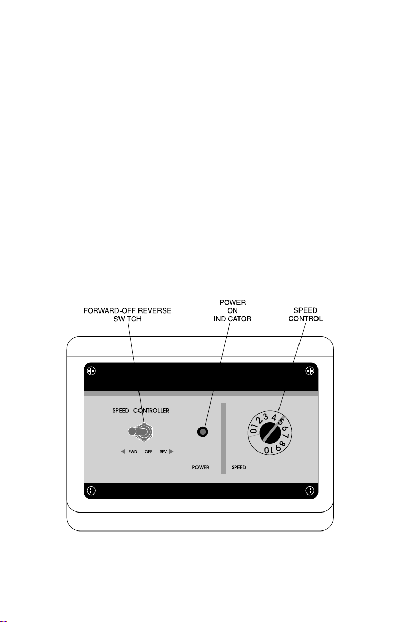
The variablespeed Controller,Figure1andFigure2, is used to set the speed
of the Mixer Heads and provides a 100:1 adjustment range. Mixer Head
Models750-0230and750-0240 are used formixinglowerviscosityfluidsand
have a 0.375 in collet and through-shaft design that accepts 0.375 in mixer
shafts.Models750-0210and 750-0220provideahightorqueoutputatspeeds
up to 180 r/min for mixing higher viscosity fluids and have a JACOBS
chuck that accepts stirring shafts from 5/16 in to 3/8 in.
®
-type
Figure 1 Readouts and Controls
–3–

DESCRIPTION
The heavy-duty modular mixing system has been designed toaccommodate
a wide variety of small batch mixing applications.Its modular design allows
the user to select from four different Mixer Heads — from low speed/high
torque heads (model 750-0210 and 750-0220) for high viscosity applications
to high speed/low torque heads (750-0230 and 750-0240) for blending and
shearing applications.
Models 750-0210 and 750-0220 high-torque mix ers use a JACOBS-type
chuck and accept shafts from 5/16 in to 3/8 in. The in-line shaft rotates at
speeds from 2 to 900 r/min depending on the model.
Models 750-0230 and 750-0240 high-speed mixersuse a 0.375 in collet and
have a through shaft design that accepts stirring shafts up to 0.375 in in
diameter. The through-shaft design provides quick depth adjustment of the
mixerb lade .These mixersoperateatspeeds from23to6000r/mindepending
on the model.
The Controller ensures accurate, dependable motor speed (mixing) control,
with“softstart”andsmoothgradualadjustment to thespeedsetting.Constant
speed with a 100:1 adjustment range is maintained electronically via
automatic compensation for changes in load torque demands — at both high
and low speeds. Built-in motor current compensation minimizes speed drift
with changes in load. Motor current limiting protects the system in case of a
locked rotor condition.Output circuit protection protects against inadvertent
output shorting.
Themotorisatotallyenclosed,non-ventedpermanent-magnetdirect-current
motor.Models750-0210and750-0220 are ratedat1/15hp.Models750-0230
and 750-0240 are rated at 1/10 hp.Mixer rotation is reversible.
Figure 2 Controller Rear Panel
–4–

INSTALLATION AND SETUP PROCEDURE
TheMixerHeadsareequippedwithanadjustabletiltmountingassembly.The
mounting assembly is designed to be attached to an optional mixer support
stand, or tank clamp. Components supplied as part of the mixer package
include the following:
• Mixer Head with 6-ft cable
• Controller with 6-ft line cord
• JACOBS-type chuck on high-torque mixers
• 0.375 in collet on high-speed mixers
• Adjustable tilt mounting assembly with support rod
Installation of Adjustable Tilt Mounting
Perf orm the following steps.
WARNING: Never insert or remove the mixer shaft/
impeller while the mixer shaft is rotating.
1. Attach Mixer Head to adjustable tilt mounting assembly as follows:
a. For models 750-0210 and 750-0220, attachmounting assemblywith
four screws and lockwashers.(See Figure 3.)
Figure 3 750-0210 and 750-0220 Mixer Mounting
b. For models 750-0230 and 750-0240, attachmounting assemblywith
two screws and lockwashers.(See Figure 4.)
–5–

Figure 4 750-0230 and 750-0240 Mixer Mounting
Note: Themixerisnowready to be attached to a support stand or toatank
clamp (not supplied). Recommended stands, tank clamps and a
double (rod) clamp are available through your dealer.Part numbers
are listed in ACCESSORIES.
Installation Using a Support Stand
1. Set up support stand in accordance with the manufacturer’sinstructions.
2. Attach a double (rod) clamp to the vertical rod on the support stand and
tighten clamp screw. (See Figure 5.)
3. Slide rod of adjustabletiltmountingassemblyintoclampandsecurewith
clampscrew.
4. Selectanimpellerandshaftf ortherequir edoperati onandinstal lasf ol lows:
a. Place impeller on shaft and tighten set screw.
b. For high-torque mixers, slide the shaft of the stirring device into the
JACOBS-chuck and tighten chuck with key supplied.
c. For high-speed models, slide the shaft through the collet and
hand-tighten collet.
5. Place support stand legs around vessel.Tiltangle is adjustable from 0 to
30 degrees.
WARNINGS: Exercise extreme care when adjusting mixer
height and/or position to avoid personal
injury. Never make these adjustments while
the mixer shaft is rotating.
Mixer shafts must be inserted into high speed
through-shaftmixersatleast3in(7.6cm)and the
collet hand-tightened firmly to ensure adequate
shaft retention. Keep mixer shafts as short as
possibletoreduceresonantvibrationscausedby
shaft flexing at higher speeds.
–6–

c. Place Controller on platform and proceed to step 9.
8. To install the pivot mount, proceed as follows:
a. Remove the two cap nuts from the mounting studs on bottom of
Controller.
b. Position pivot mount bracket over two studs, re-install two cap nuts
and tighten.
c. Attach a double (rod) clamp to the vertical support rod on the stand
and position so that pivot mount bracket will be clear of Mixer Head.
d. Slidethemountingrodofthepivotmountbrack etintothedouble(rod)
clamp and tighten clamp.
e. Adjust position of Controller by first loosening knob on piv ot mount
bracket, adjusting position and then retightening knob.
WARNING: Check that all cords are clear of any moving
parts and not subject to splashes or spills.
9. Connect the 6-ft.cable between the MixerHead and the Controller rear
panel.
10. Check that the SPEED control is set fully counterclockwise (0) and that
the FWD-OFF-REV switchis in the OFF position.
11. Connect the 6-foot line cord from the Controller to a 90–130V AC 50 or
60 Hz 3-wire grounded power source.
WARNING: Be sure the SPEED control is fully
counterclockwisebeforethePOWERswitchis
placed in the FWD or REV positions.
The Mixer is now ready to operate.
Installation using a Tank Clamp
The Tank Clamp is attached to the side of a tank and supports both the Mixer
Head and the Controller.(See Figure 6.)
1. Position the tank clamp over the edge of the tank with large knob to the
outside of tank.
2. Allow clamp to rest on edge of tank for added stability, and tighten knob.
3. PositionMixerHeadovermaterialtobe mixedandinsert mixermounting
shaft into upper hole in tank clamp.Tighten locking knob securely .
4. Select an impeller and shaft f or the required operation and install as
follows:
–8–

MIXER
HEAD
TANK
CLAMP
CONTROLLER
PLATFORM
Figure 6 Typical Mixer Setup Using a Tank Clamp
a. Place impeller on shaft and tighten set screw.
b. For high-torque mixers, slide the 5/16 in to 3/8 in shaft of the stirring
device into the JACOBS-chuck and tighten chuck.
c. Forhigh-speedmodels,slidethe0.375in shaft through thecolletand
tighten collet. Be sure only 0.0375 in (±0.0005) shafts are used.See
your dealer for obtaining proper shaft size.Referto ACCESSORIES
for part numbers.
DANGER: Do not operate mixers where explosive vapors or
flammable materials exist. Death or serious injury
could result. Check NEC and local codes before
installing.
WARNINGS: Exercise extreme care when adjusting mixer
height and/or position to avoid personal injury.
Never make these adjustments while the mixer
shaft is rotating.
Mixer shafts must be inserted into high speed
through-shaft mixers at least 3 in (7.6 cm) and the
collet hand-tightened firmly to ensure adequate
shaft retention. Keep mixer shafts as short as
possible to reduceresonantvibrations caused by
shaft flexing at higher speeds.
–9–

5. PositiontheheightoftheMixer Head onhigh-speedmodelsbyloosening
the collet and positioning the shaft.
Note: The Controller can be placed on any flat surfacewithin 6 ft (1.8 m) of
the Mixer Head and can be mounted on a support platf orm (not
supplied) or a pivot mount (not supplied). Refer to ACCESSORIES
forpartnumbers.Toattachthesupport platform, proceed withstep6.
To attach the pivot plate, proceed with step 7. If Controller is placed
elsewhere, proceed with step 8.
6. To install the support platform, proceed as follows:
a. Slide the mounting rod of the support platform into the lower hole on
the tank clamp and tighten clamp.
b. Place Controller on platform and proceed to step 8.
7. To install the pivot mount, proceed as follows:
a. Remove the two cap nuts from the mounting studs on bottom of
Controller.
b. Position pivot mount bracket over two studs, re-install two cap nuts
and tighten.
c. Slide the mounting rod of the pivot mount bracket into the lower hole
on the tank clamp and tighten clamp.
d. Adjust position of Controller by first loosening knob on pivot mount
bracket, adjusting position and then retightening knob.
8. Connect the 6-foot cablebetweentheMixerHeadandtheControllerrear
panel.
9. Check that the SPEED control is set fully counterclockwise (0) and that
the FWD-OFF-REV switchis in the OFF position.
10. Connect the 6-foot line cord from the Controller to a 90–130V AC 50 or
60 Hz 3-wire grounded power source.
WARNINGS: Check that all cords are clear of any moving
parts and not subject to splashes or spills.
Be sure the SPEED control is fully counter-
clockwisebeforethe POWER switch is placed
in the FWD or REV positions.
The Mixer is now ready to operate.
–10–

OPERATION
Be sure to follow these precautions when using the Mixer Controller System:
Always wear appropriate eye protection when mixing any kind of fluid.
Avoi dwearinglooseclothingthatma ybe caught by arotatingmixershaft.
To stoptheMix erHead inanemergency,placetheFWD/OFF/REV switch
in the OFF position or remove the power plug.
WARNING: Be sure the SPEED control is fully counter-
clockwisebeforethe POWER switchis placed
in the FWD or REV positions.
The FWD position causes the shaft to rotate in a counterclockwise direction
whenviewed from the impeller.TheSPEEDcontrol preciselysetstheoutput
speed of the shaft. The Controller has a range of 100:1 depending on the
model; shaft speed can be as low as 2 r/min or as high as 6000 r/min. The
green LED indicator illuminates whenev er the FWD-OFF-REV switch is in
either the FWD or REV position.
WARNINGS: Use care when settingthe operatingspeed of
the mixer. Operation at high speeds in small
mixing vessels could result in hazardous
splashing on the operator and equipment.
When running at full speedand load at higher
ambienttemperatures,theMixerHeadmayget
very hot to the touch.
Never insert or remove the mixer shaft/
impeller while the mixer shaft is rotating.
Set the SPEED Control to a setting that provides the desired mixing speed.
Allow about 20 minutes run-intime to allow warm-up drift to become minimal.
–11–

Cleaning the Mixer/Controller System
DANGER: NevercleantheControllerorMixerHead while
power is applied to the system.
Keep the Mixer housing and Controller enclosure clean by using a mild
detergent.Never immerse or use excess fluid.
Replacement Parts
Nouser-serviceablepartsare
dealer.
The following parts
Description Part Number
Speed Control Knob B-1083-0035
Motor Brushes (2) 07520-04
Brush Cap (1) A-2542-CR
JACOBS-type Chuck Assembly (-0210 and -0220) B-2857-0012
Chuck Key (-0210 and -0220) A-1377-0002
Collet Nut (-0230 and -0240) A-3535-0012
Pivot Assembly Knob (1) B-1083-0039
Contact your dealer if you have service needs.
are
inside
ofthisinstrument.Referservicing toyour
user replaceable.
–13–
 Loading...