

Page 1
For optimal performance of the Stinger VIP it is
important to carefully follow the directions provided
in this installation manual. For questions please call Stinger
technical support at +31 252 41 49 50. For more information,
check www.stinger.com
Please first confer with the customer to determine the desired
position for the VIP Display in the car. We advise to place the VIP
Display Holder so that the display will be easily visible for - and
within comfortable reach of - the driver.
DC
L
K
M
A B
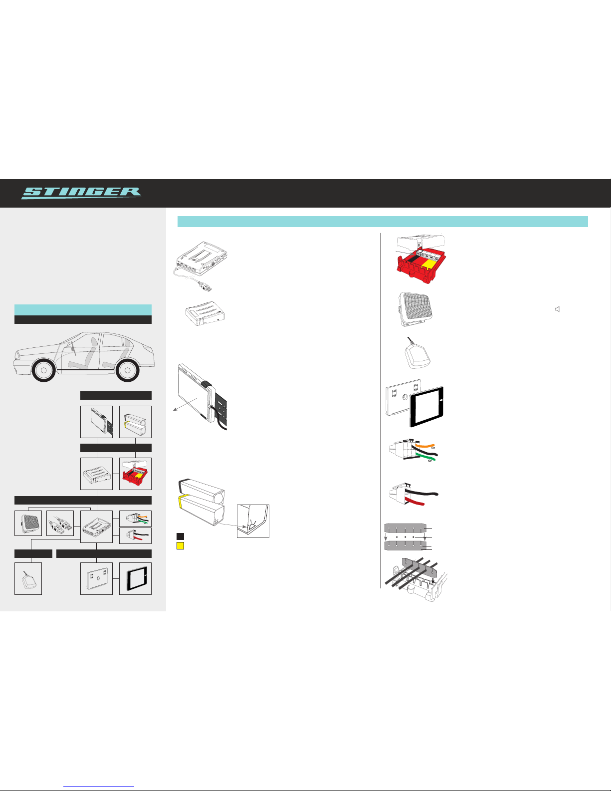
Module locations
In or behind the bumper/grill
Under the bonnet
A HD Antenna
B Laser Receiver Square (F&R)
Laser Transmitter Square (F&R)
C Extention Box (F&R)
D Laser Analyzer Box (F&R)
E Speaker
F USB Cable
G VIP Computer
H I/O Plug
J Power Plug
K GPS Antenna
L VIP Display Holder
M VIP Display
Schematic view
Stinger VIP - Installation manual INT-V3.1 - © Stinger 2015 - Changes reserved
Step by Step inStructionS
1. VIP Computer
The VIP Computer must be placed in a humidity-free location
such as in or under the dashboard.
• Mount the VIP Computer with tie-wraps or screws.
• note: Connect one end of the USB Cable to the VIP Computer
and make sure the other end remains easily accessible, for
instance lying free in the glove box.
2. Extension Box
Place the Extension Box horizontally (as depicted) under the
hood, in a reasonably humidity-free location.
• Connect the Extension Box for the front of the car to the
FRONT port of the VIP Computer.
• Connect the Extension Box for the rear of the car to the
AUX port of the VIP Computer.
Do not yet close the lid of the Extension Box.
3. HD Antenna (standard installation)
Place the HD Antenna at the front of the car behind the
bumper or spoiler, preferably behind a flat and smooth plastic
surface, and not behind metal or the grill.
• The HD Antenna must be installed so it’s both horizontally
and vertically flush to the road, with the cable connection
on the left or right side. The large, smooth side must face
straight forward.
• Connect the HD Antenna to any port of the Extension Box.
(The Antenna must never be connected to the Laser Analyzer
Box: this can cause a short-circuit.)
• For maximum performance, please make sure the antenna
receives sufficient airflow on all sides for cooling.
• Please see reverse side of this sheet for MultaRadar CD
optimized installation.
4. Lasers
Connect the Lasers to the Laser Analyzer Box: a Laser Receiver
to a Receiver port (red). A Laser Transmitter to a Transmitter
port (yellow).
Attention: The Laser Transmitter has a
‘horizon’ icon embossed on the front lens
indicating this side must go below.
To ensure optimal laser functionality, please refer to the exact
laser installation instructions in the provided Stinger Laser
Analyzer Installation Manual. Download available at:
www.stinger.com/manuals
5. Laser Analyzer Box
Place the Laser Analyzer Box horizontally (as depicted) under the
bonnet, in a reasonably humidity-free location.
• Connect the Laser Analyzer Box to the Extension Box
with the plug in the left “CC port” and connect the
other end to any of the ports on the Extension Box.
Do not yet close the lid.
6. Speaker
Place the speaker under the dashboard.
• Connect the module to the Speaker port ( ) of the VIP
Computer.
7. GPS Antenna
Place the antenna on the dashboard. If the car has a heat-repelling
windshield, it is better to place the antenna outside the cabin of
the car, for instance in a space at the top end of the bonnet.
• Connect the cable of the antenna to the GPS port of the VIP
Computer.
8. VIP Display & VIP Display Holder
Place the VIP Display Holder at a convenient location for the driver.
• Connect the module to the DISPLAY port of the
VIP Computer.
• Place the VIP Display on the VIP Display Holder.
9. 8-pole I/O plug
• Connect the orange wire to the ignition-actuated 13.8V
battery power (+15).
• If so desired, attach the green Mute-cable to the Mute-wire
of the radio.
• The black wire is for future use.
10. 2-pole power plug
• Connect the red wire to the 13.8V battery power (+30).
• Connect the black wire to a ‘clean’ metal ground-point of
the car chassis.
11. Closing the Extension Box and Laser Analyzer Box
After all the cables have been connected, it is important to close
the boxes (see steps 2 and 5) in a water resistant manner. Place
the cables in the holes of the opposite facing ‘rubber seals’ (see
example). This prevents moisture from getting into the box.
Next, place the rubber seals with the now inserted cables into
the slot, as depicted in the example on the left. Make sure the
rubbers are pushed down all the way using silicone spray to
facilitate this. Put the lid back on so that it is tight and secure.
VIP
Installation manual
Port to the
Extension Box
Facing
forward
Bl
Bl
Red
Rubber
seal
Rubber
seal
Cut outs
Cable
H
J
GE F
Bl
Bl
Red
Under the dashboard
In the cockpitCar specific
H J
F
E
G
K
D
D
A
A
B
B
C
C
ML
Laser Square - Recievers
Laser Square - Transmitters
Page 2
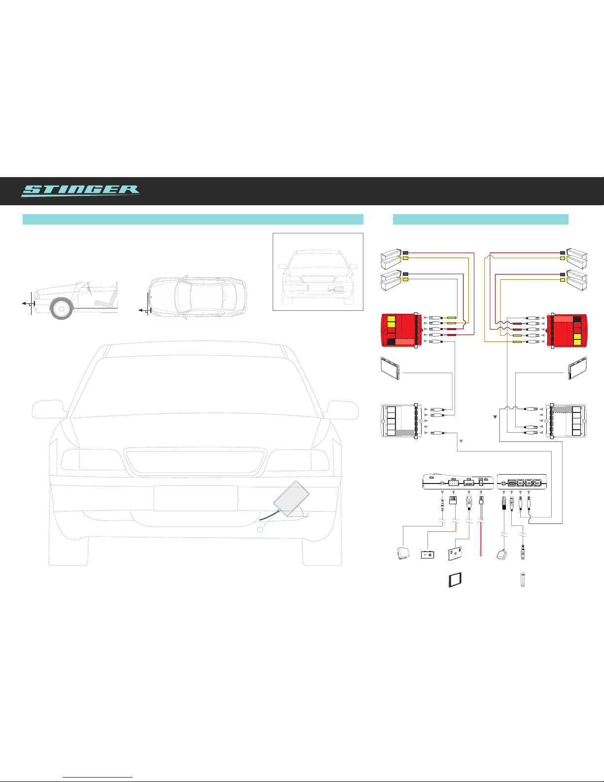
Standard antenna installation
wiring diagram
COMPUTER CENTER
GPSSPEAKER SWITCHED
POWER SUPPLY
13.8 V (+15)
VIP DISPLAY
HOLDER
CONSTANT
POWER SUPPLY
13.8 V (+30)
TO THE
USB STICK
HD ANTENNA
EXTENSION BOX #1
LASER ANALYZER BOX #1
FRONT REAR
LASER ANALYZER BOX #2
LASERSLASERS
Port 1
Port 2
Port 3
Port 4
Control
unit
Port 1
Port 2
Port 3
Port 4
Port 1
Port 4
Port 3
Port 2
EXTENSION BOX #2
HD ANTENNA
YELLOW
YELLOW
RED
RED
YELLOW
RED
RED
To FRONT
port
To AUX
port
YELLOW
Port 1
Port 4
Port 3
Port 2
Control
unit
FRONT AUX
multaradar cd optimized inStallation
HD Antenne installation for MultaRadar CD
We advise to have the HD Antenna installed horizontally. However, those drivers who wish to have
optimized reception of MultaRadar CD signals can choose to have the antenna mounted diagonally,
as explained in the overview below.
2
45°
1. Diagonally place the antenna behind the bumper or
spoiler, with the smooth surface facing forward.
2. From the point of view of the driver, the cable connection must be on the
bottom right of the antenna.
Take note: If, from the point of view of the driver, the cable connection is on
the top right or bottom left, the reception will be strongly reduced.
90
o
Antenna must face outward
and parallel to the road
90
o
Aim antenna straight forward
 Loading...