

Page 1
Stinger ELEV8 or HEIGH10® Radio Replacement Kit
for Jeep Wrangler JL and Jeep Gladiator JT Vehicles
SRK-JW18EH
© 2020 AAMP Global. All rights reserved. PAC is a Power Brand of AAMP Global.
AAMP Global is not aliated with FCA US LLC. Jeep® is a registered trademark of FCA US LLC. The terms
OEM, Jeep®, Wrangler®, and Gladiator® all terms are used strictly for identication purposes only. It is not
implied that any part listed is a product of, or approved by, Fiat Chrysler Automobiles.
Introduction and Features
The SRK-JW18EH is a complete radio replacement kit with integrated climate control retention for select Jeep Wrangler
JL and Jeep Gladiator JT vehicles. All modules and cables are included to retain important features of the factory
system, including: steering wheel-mounted radio controls, factory reverse camera, USB ports, and AM/FM reception.
Data integration with the vehicle and the Stinger ELEV8 or Stinger HEIGH10® radio (sold separately) allows for the
retention and addition of the following features: vehicle performance gauges and information, climate controls, vehicle
settings, factory amplier control, and forced camera activation. Simplied installation and setup menus allow direct
programming of camera triggers, steering wheel controls, and other settings of the radio and CH4A-JW18 interface.
See Important Notes (next section) for additional information.
Plug & Play wiring harnesses and cables allow for quick and easy installation without the need to cut or splice any
wiring.
Important Notes
We recommend reading this manual thoroughly to familiarize yourself with the entire process
1. Does Not Retain:
Cluster Display Features
• Compass (when equipped with 7” or 8.4” screen)
• Clock
• Phone pop-ups
• Navigation pop-ups
Factory Amplier Features
• Speed Controlled Volume
2. When connected properly, the USB port inside the center console will function for Apple Carplay/Android Auto, and all
other USB ports will be used for USB thumb drives and charging only.
3. Ensure that the CH4A-JW18, PL1, and RPA-HD1 modules have been updated to the latest version of rmware
before installing into the vehicle. Refer to the Updating Firmware section at the end of the manual for rmware update
instructions.
4. When connecting an HDMI streaming device to the RPA-HD1, use an HDMI extension cable to position it away from the
module to ensure proper functionality. We recommend placing the HDMI device in the glove box. Failure to follow the
directions may result in module malfunction.
prior to beginning the installation.
Uconnect Features
• Uconnect Access Remote Start / Lock / Unlock
• SOS / Assist
• Vehicle Location Service
• WiFi-Hotspot
SiriusXM Guardian Services
• SiriusXM Radio
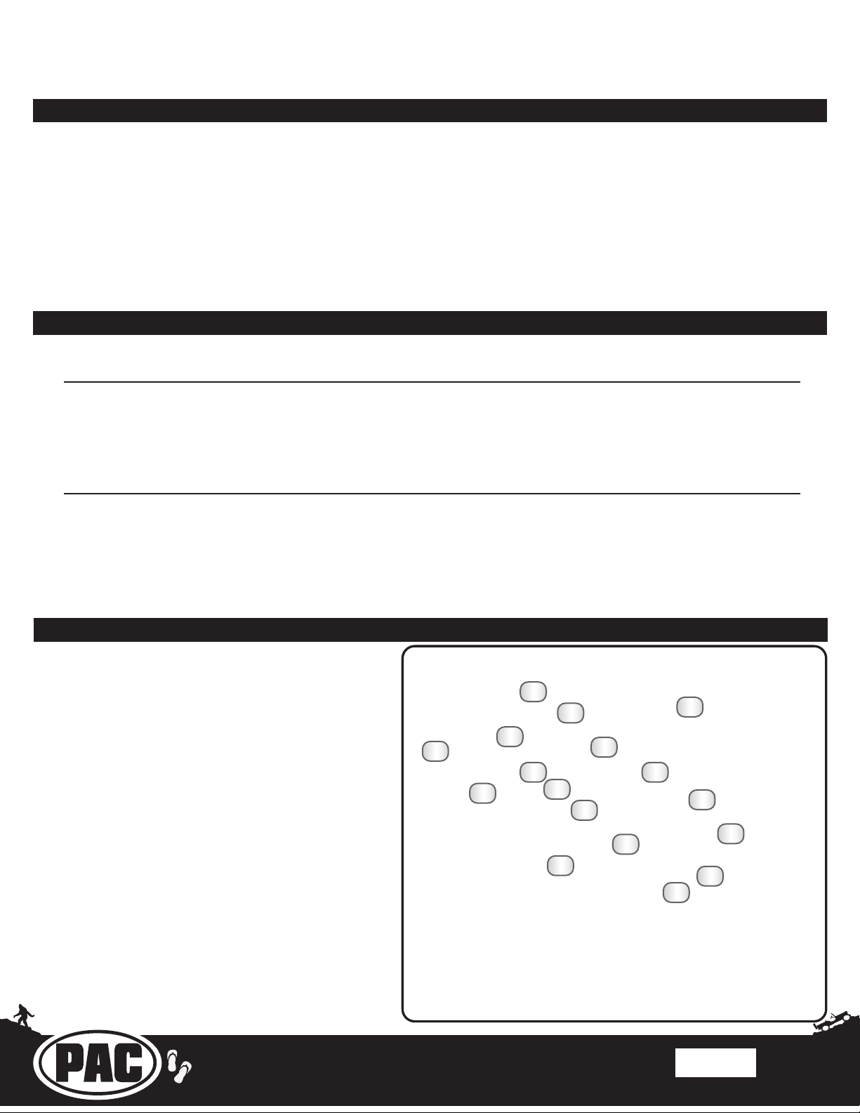
Tools Needed; Included Components
Tools needed for installation: 7mm socket, 10mm socket, ratchet,
ratchet extension, T20 torx screwdriver, T25 torx screwdriver,
pick tool or small athead screwdriver, plastic panel removal tool
(example - PAC part number TL-PRY2).
1. ELEV8 / HEIGH10 Display Mounting Panel
2. 18” Data Harness (10P-2-10P-18)
3. CAN-Bus Connection Harness (MQS4PT-36)
4. Radio Module Mounting Brackets
5. Chime Speaker Mounting Accessories
6. Screen Panel Clips and Mounting Bracket Screws
7. External Chime Speaker
8. 7’ USB Port Retention Adapter (USB-UN2)
9. AM / FM Antenna Adapter (BAA22)
10. 8” USB Hub Retention Adapter (USB-UN1)
11. 6” Data Harness (10P-2-10P-6)
12. PAC-LINK Interface Module (PL1)
13. HD Camera Retention Module (RPA-HD1)
14. Radio Replacement Interface Module
(CH4A-JW18)
15. Satellite Antenna Adapter (SAT-01)
16. 12” HDMI Cable
17. Main Wiring Harness (RPK-JW18-HAR)
15
16
2
3
9
10
11
17
4
12
13
1
5
6
7
8
14
Rev: v3
Date:100620
Page 1
Page 2
Stinger ELEV8 or HEIGH10® Radio Replacement Kit
for Jeep Wrangler JL and Jeep Gladiator JT Vehicles
SRK-JW18EH
© 2020 AAMP Global. All rights reserved. PAC is a Power Brand of AAMP Global.
AAMP Global is not aliated with FCA US LLC. Jeep® is a registered trademark of FCA US LLC. The terms
OEM, Jeep®, Wrangler®, and Gladiator® all terms are used strictly for identication purposes only. It is not
implied that any part listed is a product of, or approved by, Fiat Chrysler Automobiles.
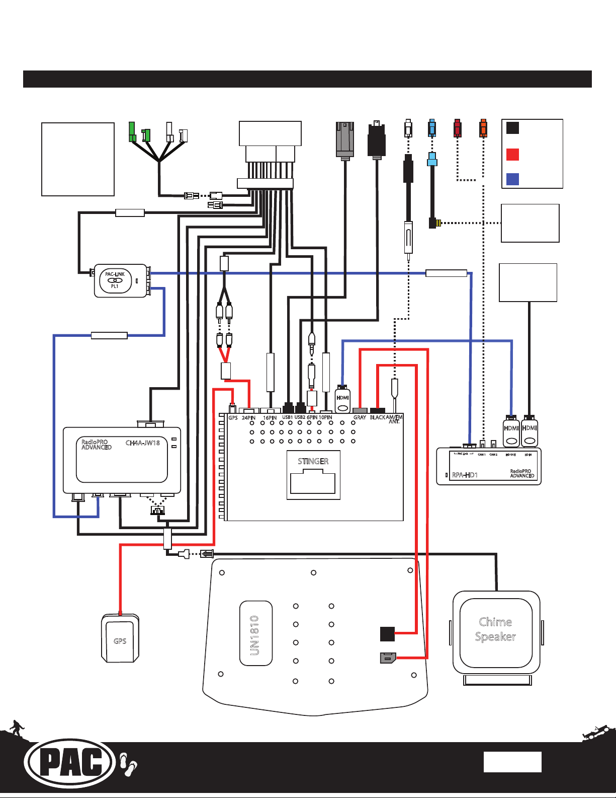
Complete Wiring Diagram Overview
*Connections shown
are all required for
full functionality of
the kit and radio. If
adding additional
components,
additional connections
will be needed.
RPK-JW18-HAR
USB-UN2USB-UN1
Main Harness
Connection
Stinger
Connection
PAC
OR
Connection
10P-2-10P-6
RadioPRO
ADVANCED
PAC-LINK
PAC-LINK
PL1
CH4A-JW18
AUX
A/V IN
Connect to
SXV300 Satellite
Radio Tuner
(sold seperately)
10P-2-10P-18
Connect to
HDMI Device
(cable sold
seperately)
16PIN RADIO
USB2
24PIN 16PINGPS
USB1
SWI
10PIN RADIO
HDMI
10PIN6PIN
GR AY
BLACK
AM/FM
ANT.
PAC Link
HDMI
HDMI
CAM 2
CAM 1
HD OUT
HD IN
STINGER
RPA-HD1
RadioPRO
ADVANCED
CHIME
GPS
UN1810
*Only required in
vehicles with Safety
Group features
Chime
Speaker
Rev: v3
Date:100620
Page 2
Page 3
Stinger ELEV8 or HEIGH10® Radio Replacement Kit
for Jeep Wrangler JL and Jeep Gladiator JT Vehicles
SRK-JW18EH
© 2020 AAMP Global. All rights reserved. PAC is a Power Brand of AAMP Global.
AAMP Global is not aliated with FCA US LLC. Jeep® is a registered trademark of FCA US LLC. The terms
OEM, Jeep®, Wrangler®, and Gladiator® all terms are used strictly for identication purposes only. It is not
implied that any part listed is a product of, or approved by, Fiat Chrysler Automobiles.
This installation manual will cover the necessary order of procedures to complete the installation
eciently and to avoid redoing any steps along the way. The order will be as follows; Disassembly,
Radio Unit Mounting Preparation, Radio Unit Harness Connections and Preparation, In-Vehicle Harness
Connections and Preparation, Radio Unit Installation, and Reassembly.
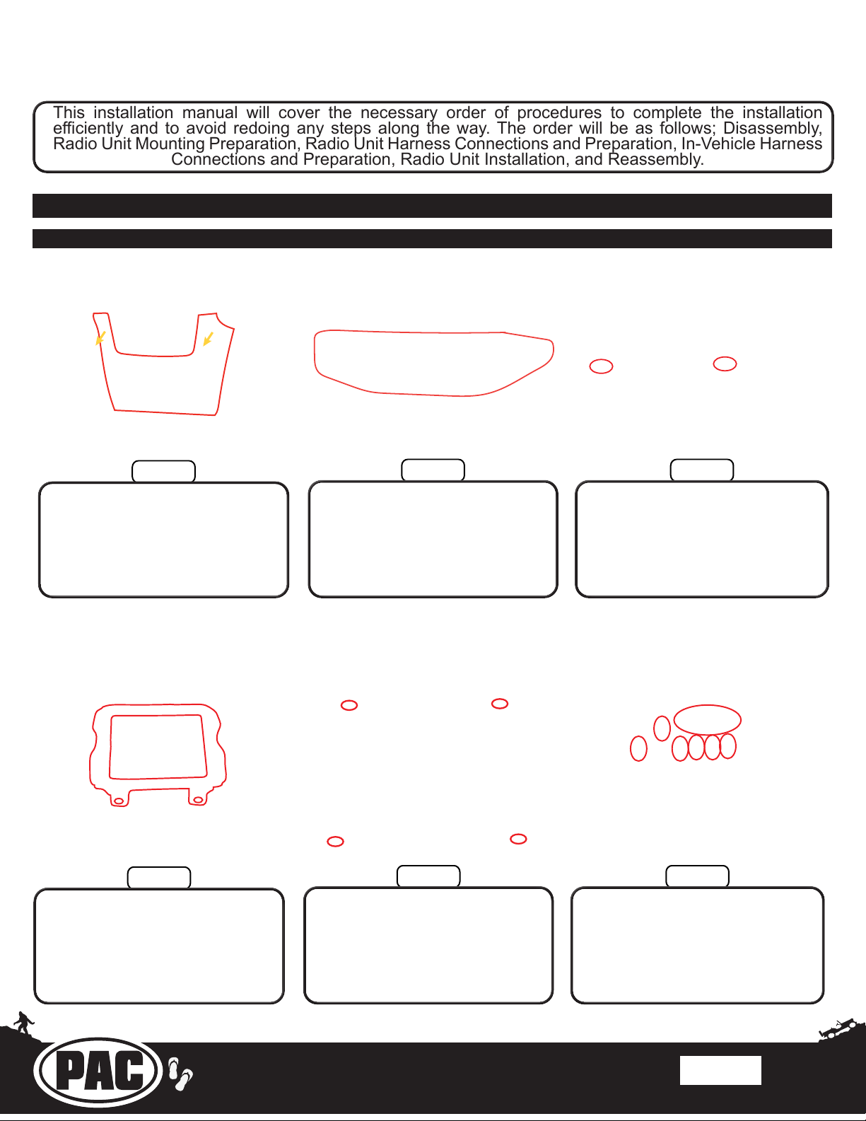
Section 1: Disassembly
Part One: Radio Removal
Step 1
Pull out at the top of the knee
bolster to release the retaining
clips, then work your hands down
the edges of the knee bolster to
release the remaining clips and
remove the panel.
Step 4
Grasp the climate control panel at
the exposed left edge and pull out
to unclip the left side, then work
your ngers around the remaining
edges of the panel to fully unclip
it.
Step 3Step 2
Disconnect the push-to-start button
and climate control connectors
from the back of the climate control
panel and remove.
Step 6Step 5
Remove the two 7mm screws
securing the radio bezel to the
dash, then pull outward on
the radio bezel to unclip it and
remove.
Remove the four 7mm screws
securing the radio in place, then
lift the radio out of the radio
cavity.
Disconnect the antenna and USB
connectors from the back of the
radio, then disconnect the 52-
pin dock-and-lock connector and
remove the radio.
Rev: v3
Date:100620
Page 3
Page 4
Stinger ELEV8 or HEIGH10® Radio Replacement Kit
for Jeep Wrangler JL and Jeep Gladiator JT Vehicles
SRK-JW18EH
© 2020 AAMP Global. All rights reserved. PAC is a Power Brand of AAMP Global.
AAMP Global is not aliated with FCA US LLC. Jeep® is a registered trademark of FCA US LLC. The terms
OEM, Jeep®, Wrangler®, and Gladiator® all terms are used strictly for identication purposes only. It is not
implied that any part listed is a product of, or approved by, Fiat Chrysler Automobiles.
Section 1: Disassembly (cont.)
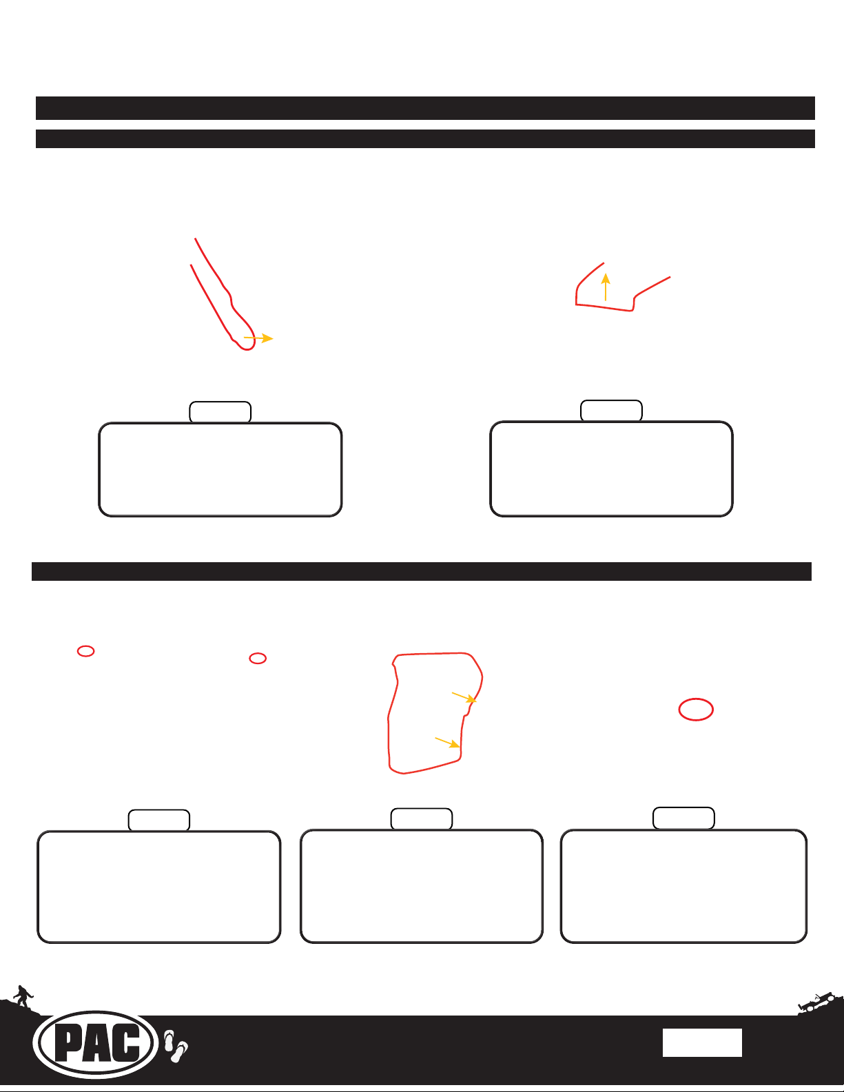
Part Two: Glove Box Removal
Step 1
Open the glove box and unclip
the soft-open sliding arm clasp
from the left side of the glove box.
Part Three: Center Console Panel Removal
Step 2
Push up on the glove box stop
tab to allow the glove box to
fall forward out of the glove box
opening, then unhinge the bottom
of the glove box and remove.
Step 1
Open the center console storage
lid, then remove the two T20 torx
screws securing the rear console
panel in place.
Step 2
While pulling the panel towards
the rear of the vehicle, use a
plastic panel removal tool to
release the clips securing the
panel in place and remove.
Step 3
Disconnect the inner center
console USB port connector.
Rev: v3
Date:100620
Page 4
Page 5
Stinger ELEV8 or HEIGH10® Radio Replacement Kit
for Jeep Wrangler JL and Jeep Gladiator JT Vehicles
SRK-JW18EH
© 2020 AAMP Global. All rights reserved. PAC is a Power Brand of AAMP Global.
AAMP Global is not aliated with FCA US LLC. Jeep® is a registered trademark of FCA US LLC. The terms
OEM, Jeep®, Wrangler®, and Gladiator® all terms are used strictly for identication purposes only. It is not
implied that any part listed is a product of, or approved by, Fiat Chrysler Automobiles.
Section 1: Disassembly (Cont.)
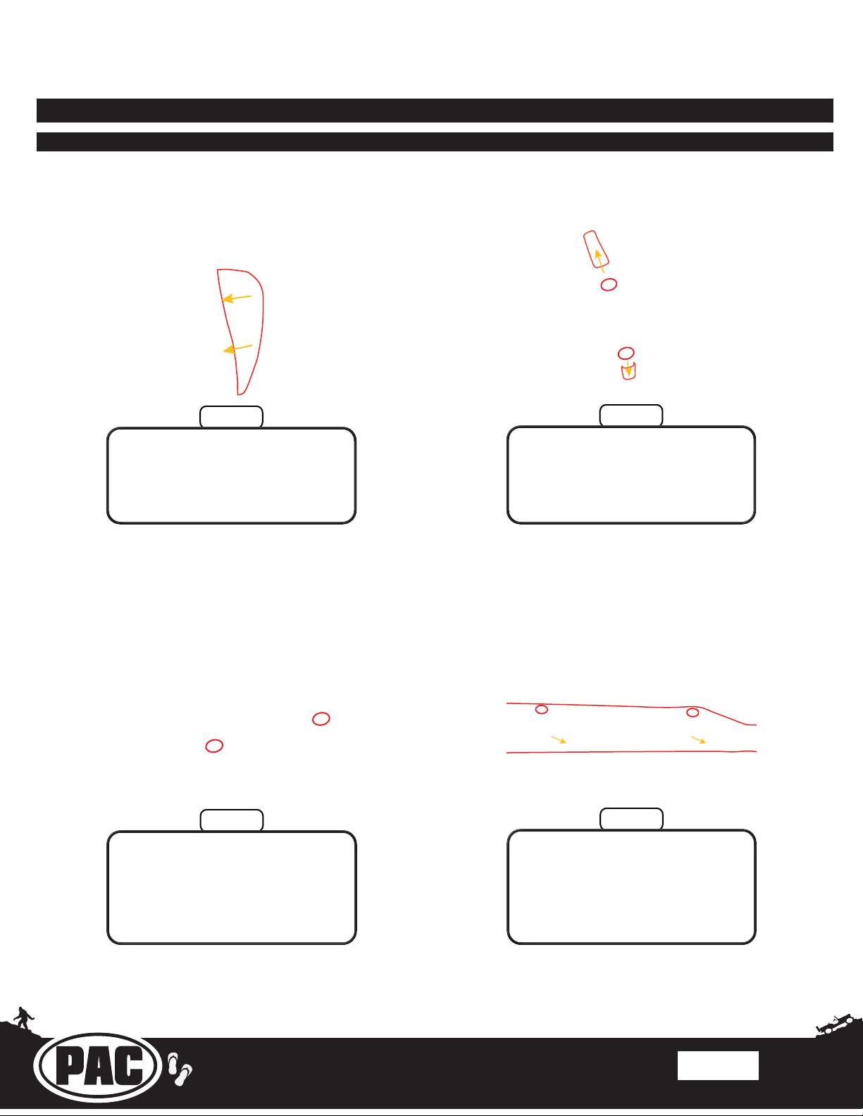
Part Four: Door Sill Trim Removal
Step 1
Use a plastic panel removal tool
to remove the panel on the driver
side of the dash.
Step 3
Step 2
Use a plastic panel removal tool
to open the driver side handle
bolt covers, then remove the two
10mm bolts.
Step 4
Remove the two T25 screws on
the underside of the driver side
upper door seal trim.
Remove the two T25 screws on
the inner-most side of the driver
side upper door seal trim; then,
while pulling towards the middle
of the vehicle, use a plastic panel
removal tool to remove it.
Rev: v3
Date:100620
Page 5
Page 6
Stinger ELEV8 or HEIGH10® Radio Replacement Kit
for Jeep Wrangler JL and Jeep Gladiator JT Vehicles
SRK-JW18EH
© 2020 AAMP Global. All rights reserved. PAC is a Power Brand of AAMP Global.
AAMP Global is not aliated with FCA US LLC. Jeep® is a registered trademark of FCA US LLC. The terms
OEM, Jeep®, Wrangler®, and Gladiator® all terms are used strictly for identication purposes only. It is not
implied that any part listed is a product of, or approved by, Fiat Chrysler Automobiles.
Section 2: Radio Unit Mounting Preparation
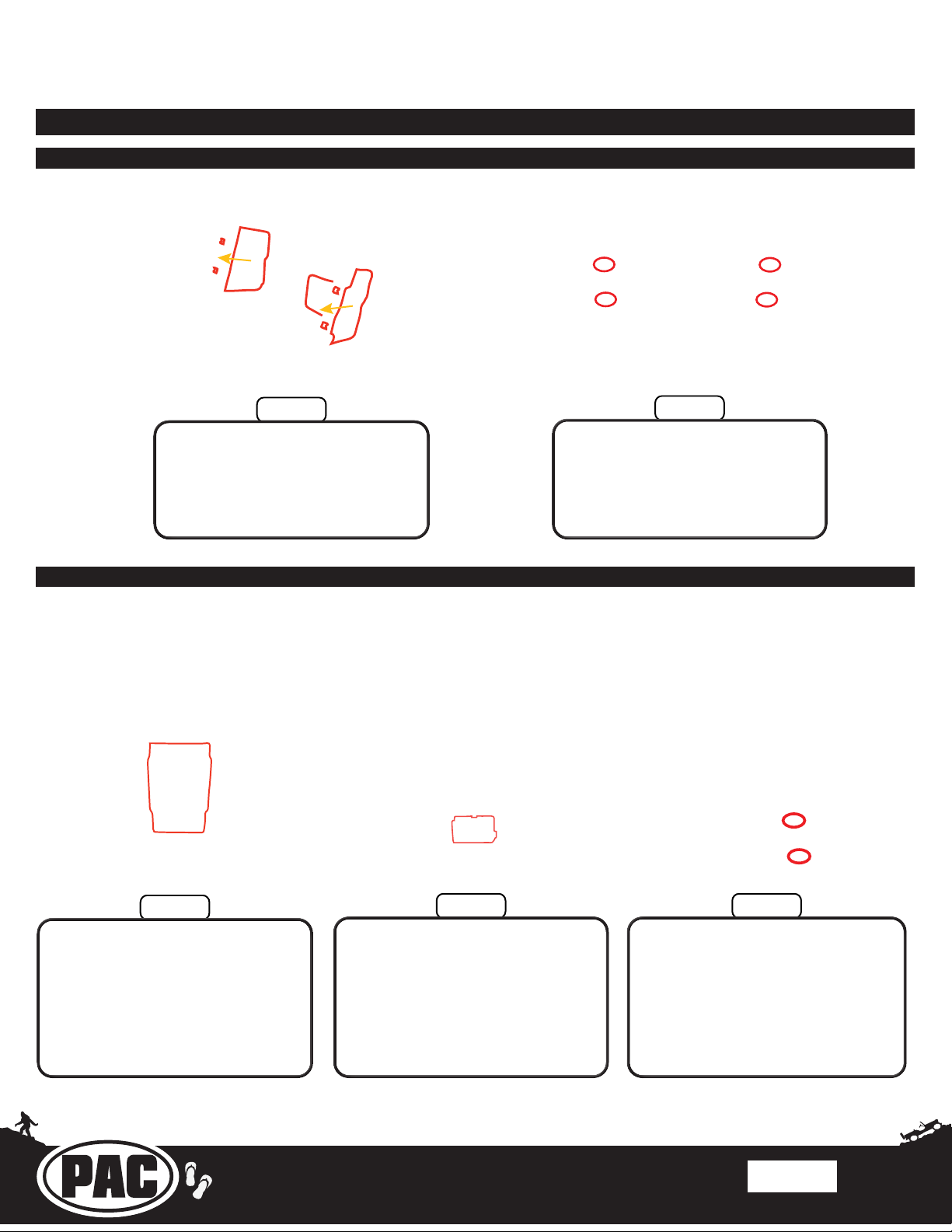
Part One: Assembling the Radio Module Mounting Brackets
Step 1
Slide the left and right side
brackets (marked by the letters
LH and RH) into the back of the
main bracket (the orientation of
the main bracket is marked by the
part number at the top).
Part Two: Mounting the Interface Modules and Stinger Radio Module
Note: It does not matter what the DIP switches on the
CH4A-JW18 module are set to.
Step 2
Secure the side brackets to
the main bracket using the four
#10x3/8 Phillips course threaded
screws.
Step 1
Mount the CH4A-JW18 module to
the left and right inner mounting
tabs of the radio module
mounting brackets using zip ties.
Ensure the module is oriented
with the part number (CH4A-
JW18) on the right side.
Mount the PAC-LINK module to
the lower part of the CH4A-JW18
module using a piece of the
provided double-sided tape.
Step 3Step 2
Mount the Stinger radio module
onto the side brackets using the
four M5x10 Phillips screws (only two
shown). Ensure that the ports for
connections on the radio module are
facing down.
Rev: v3
Date:100620
Page 6
Page 7
Stinger ELEV8 or HEIGH10® Radio Replacement Kit
for Jeep Wrangler JL and Jeep Gladiator JT Vehicles
SRK-JW18EH
© 2020 AAMP Global. All rights reserved. PAC is a Power Brand of AAMP Global.
AAMP Global is not aliated with FCA US LLC. Jeep® is a registered trademark of FCA US LLC. The terms
OEM, Jeep®, Wrangler®, and Gladiator® all terms are used strictly for identication purposes only. It is not
implied that any part listed is a product of, or approved by, Fiat Chrysler Automobiles.
OR
AMPLIFIED
NON-AMPLIFIED
Section 2: Radio Unit Mounting Preparation (cont.)
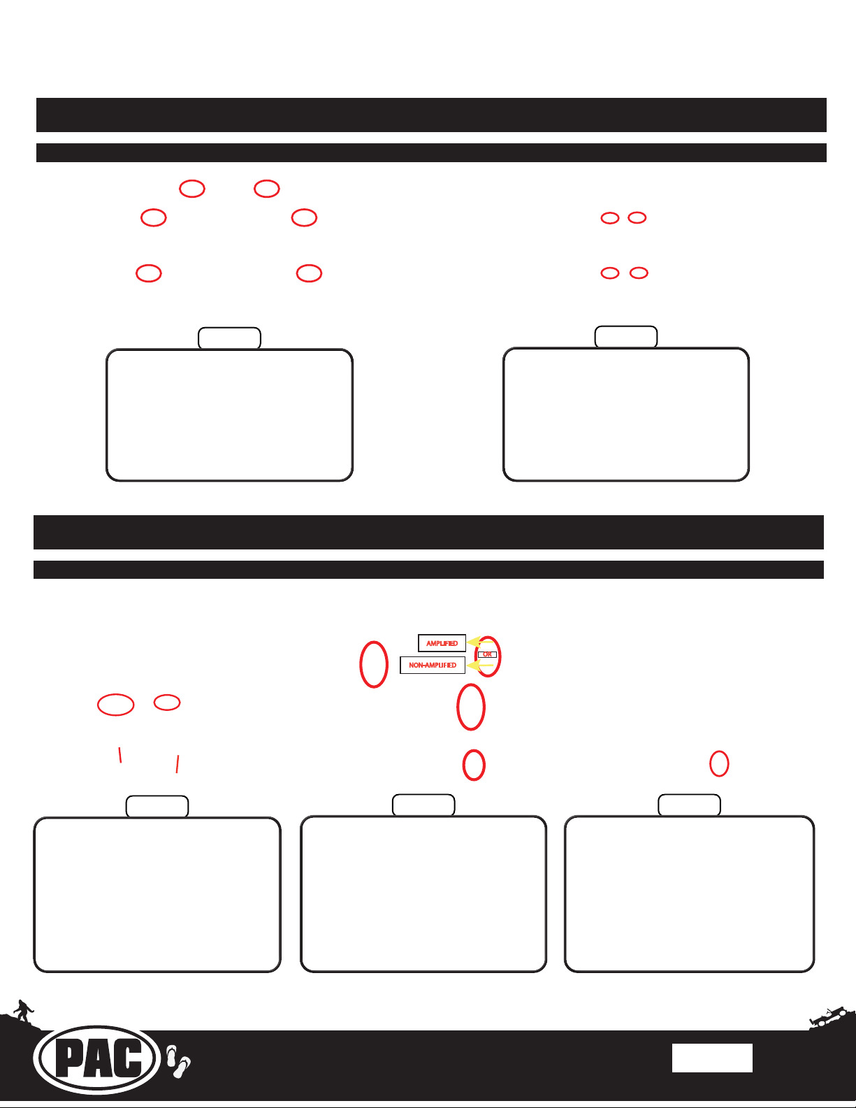
Part Three: Assembling the Screen Mounting Panel
Step 1
Install the six orange retaining
clips onto either the ELEV8 or
the HEIGH10 mounting panel
(HEIGH10 panel shown).
Section 3: Radio Unit Harness Connections and Preparation
Part One: Main Harness Connections (RPK-JW18-HAR)
Step 2
Lay the radio screen into the
mounting panel and secure it to
the panel using the four M4x12
screws included in your ELEV8
or HEIGH10 box.
Step 1
Connect the two Stinger radio
module connectors which
are labeled “16PIN RADIO”
and “10PIN RADIO” into the
appropriate ports on the Stinger
radio module.
Connect the four CH4A-JW18
interface module connectors
into the appropriate ports on the
CH4A-JW18 interface module.
Ensure that the 12-pin connector
Connect the PL1 interface module
connector labeled “PAC LINK” into
the 3-pin port on the PAC-LINK
is plugged into the correct audio
output port (this depends on if the
vehicle is equipped with a factory
amplier or not).
Step 3Step 2
interface module.
Rev: v3
Date:100620
Page 7
Page 8
Stinger ELEV8 or HEIGH10® Radio Replacement Kit
for Jeep Wrangler JL and Jeep Gladiator JT Vehicles
SRK-JW18EH
© 2020 AAMP Global. All rights reserved. PAC is a Power Brand of AAMP Global.
AAMP Global is not aliated with FCA US LLC. Jeep® is a registered trademark of FCA US LLC. The terms
OEM, Jeep®, Wrangler®, and Gladiator® all terms are used strictly for identication purposes only. It is not
implied that any part listed is a product of, or approved by, Fiat Chrysler Automobiles.
Section 3: Radio Unit Harness Connections and Preparation (cont.)
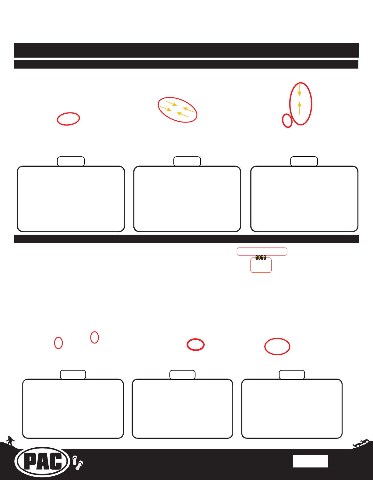
Part One: Main Harness Connections (RPK-JW18-HAR) (cont.)
Connect the white and red male
Connect the 24-pin A/V Stinger
RCA harness (provided in the
Stinger radio box) into the 24-pin
port on the Stinger radio module.
RCAs labeled “OEM AUX AUDIO”
on the RPK-JW18-HAR into the
white and red female RCAs
labeled “LINE IN / AUX IN” on the
A/V Stinger RCA harness.
Part Two: 10P-2-10P Harness and HDMI Connections
Prior to making connections to the RPA-HD1 module,
verify that all 4 of the module’s DIP Switches are set to the
up position (OFF).
Step 5Step 4
Step 6
Connect the 6-pin SWI / IR harness
(provided in the Stinger radio box)
into the 6-pin port on the Stinger
radio module, then connect the
3.5mm jack labeled “STEERING
WHEEL CONTROL” on the RPK-
JW18-HAR into the female 3.5mm
connector labeled “SWI” on the
Stinger SWI / IR harness.
DIP SWITCHES LOCATED ON TOP
SIDE OF MODULE
Step 1
Connect one end of the 6”
harness (10P-2-10P-6) into the
10-pin expansion port on the
CH4A-JW18 interface module,
then connect the other end into
either of the two 10-pin ports on
the PL1 interface module.
Step 2 Step 3
Connect one end of the 18” harness
(10P-2-10P-18) into either of the two
10-pin PAC Link ports on the RPA-
HD1 interface module. The other
end will be connected to the open
10-pin port on the PL1 interface
module after mounting the radio unit
into the vehicle.
Connect one end of the 12” HDMI
cable into the HD OUT port on the
HD1 interface module. The other
end will be connected to the HDMI
input port on the Stinger radio
module after mounting the HD1
interface module into the vehicle.
Rev: v3
Date:100620
Page 8
Page 9
Stinger ELEV8 or HEIGH10® Radio Replacement Kit
for Jeep Wrangler JL and Jeep Gladiator JT Vehicles
SRK-JW18EH
© 2020 AAMP Global. All rights reserved. PAC is a Power Brand of AAMP Global.
AAMP Global is not aliated with FCA US LLC. Jeep® is a registered trademark of FCA US LLC. The terms
OEM, Jeep®, Wrangler®, and Gladiator® all terms are used strictly for identication purposes only. It is not
implied that any part listed is a product of, or approved by, Fiat Chrysler Automobiles.
Section 3: Radio Unit Harness Connections and Preparation (cont.)
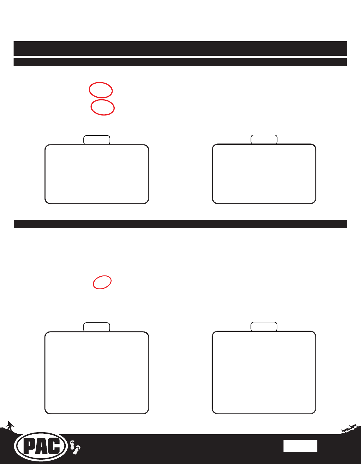
Part Three: Stinger Display Connections
Step 1
Connect one end of the 8-pin
display power harness into the
8-pin port on the Stinger radio
module, then connect the LVDS
display video cable into the LVDS
display port on the Stinger radio
module. (Both of these cables are
provided in the Stinger radio box.)
Part Four: Securing the Wire Harness
Step 2
Route the display harness and
cable through the front opening of
the main radio module mounting
bracket.
Step 1
Run a zip tie through the metal
eyelet on the connections side
of the Stinger radio module,
then tighten it down around the
main wiring harness to secure it
in place tightly against the radio
module.
Step 2
Secure each end of one
backstrap (included in the
Stinger radio box) to the plastic
eyelets on the side radio module
mounting brackets, then use
zipties to secure the factory style
52-pin connector and the rest of
the radio unit wiring to the back
strap. (The unit should resemble
the image pictured when
complete.)
Rev: v3
Date:100620
Page 9
Page 10
Stinger ELEV8 or HEIGH10® Radio Replacement Kit
for Jeep Wrangler JL and Jeep Gladiator JT Vehicles
SRK-JW18EH
© 2020 AAMP Global. All rights reserved. PAC is a Power Brand of AAMP Global.
AAMP Global is not aliated with FCA US LLC. Jeep® is a registered trademark of FCA US LLC. The terms
OEM, Jeep®, Wrangler®, and Gladiator® all terms are used strictly for identication purposes only. It is not
implied that any part listed is a product of, or approved by, Fiat Chrysler Automobiles.
Section 4: In-Vehicle Harness Connections and Preparation
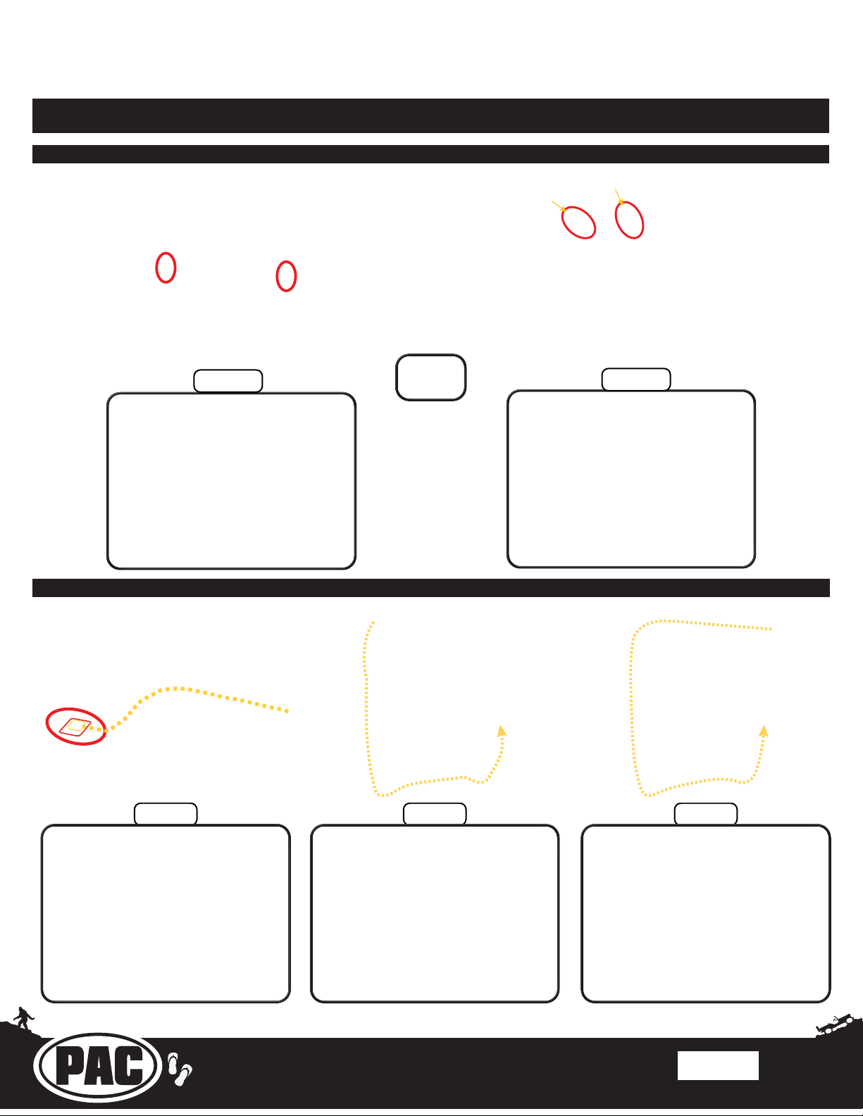
Part One: CAN Connections Harness (MQS4PT-36)
Step 1
Step 1A
Behind the glovebox, connect
the male white connector from
the MQS4PT-36 harness into the
green CAN junction block and
the male green connector from
the MQS4PT-36 harness into the
white CAN junction block, then
run the 4-pin connector on the
MQS4PT-36 harness behind the
dash to the radio opening.
Part Two: GPS Antenna and External Microphone (provided in Stinger radio box)
OR
Step 1B
If there are no open ports on the
CAN junction blocks, unplug one
factory male connector and insert
it into the same colored female
connector on the MQS4PT-36
harness, then insert the male
connector on the MQS4PT-36
harness into the now empty port
on the CAN junction block.
Clean the area next to the factory
antenna on the center roll cage
structure and stick the GPS
mounting plate to it. Then, secure
the GPS antenna to the mounting
plate (it is magnetic). Route the
cable behind the trim panels of
the roll cage over to the driver
side A-pillar.
Step 2Step 1
Route the GPS cable down the
A-pillar past the plastic dash
side panel, then route the cable
behind the lower dash below the
steering column and then up the
center stack to the radio opening.
(Secure with zip ties along the
way.)
Step 3
If you choose to use the external
microphone instead of the
internal microphone, mount it to
the upper windshield trim panel
above the rear-view mirror, then
route the cable underneath the
trim panels across the upper
windshield and follow the route
of the GPS cable to the radio
opening.
Rev: v3
Date:100620
Page 10
Page 11
Stinger ELEV8 or HEIGH10® Radio Replacement Kit
for Jeep Wrangler JL and Jeep Gladiator JT Vehicles
SRK-JW18EH
© 2020 AAMP Global. All rights reserved. PAC is a Power Brand of AAMP Global.
AAMP Global is not aliated with FCA US LLC. Jeep® is a registered trademark of FCA US LLC. The terms
OEM, Jeep®, Wrangler®, and Gladiator® all terms are used strictly for identication purposes only. It is not
implied that any part listed is a product of, or approved by, Fiat Chrysler Automobiles.
Section 4: In-Vehicle Harness Connections and Preparation (cont.)
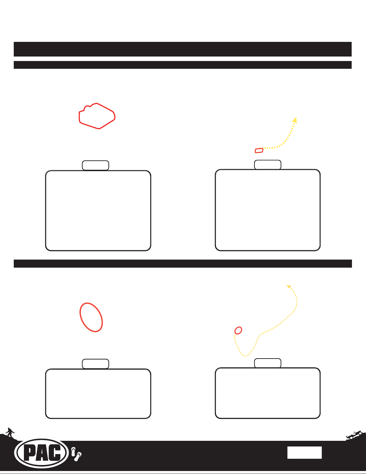
Part Three: Chime Speaker
Note: Installation of
the chime speaker
is only required in
vehicles with safety
group features.
Step 1
Remove the knobs from the
chime speaker and mount the
chime speaker bracket to the
metal brace underneath the
steering column using the double
sided tape, mounting bolts, and
wing nuts. Then, reinstall the
speaker to the mounting bracket.
(Two holes must be drilled into
the metal brace to secure the
speaker mounting bracket to it.)
Part Four: USB Retention Adapters
Step 2
Route the chime speaker cable
behind the dash panels to the
radio opening.
Step 1
Connect the USB-UN1 adapter
to the factory USB connector that
was unplugged from the factory
radio.
Step 2
Connect the USB-UN2 adapter to
the factory USB port in the back
of the center console, then route
the cable along the passenger
side of the center console to the
radio opening.
Rev: v3
Date:100620
Page 11
Page 12
Stinger ELEV8 or HEIGH10® Radio Replacement Kit
for Jeep Wrangler JL and Jeep Gladiator JT Vehicles
SRK-JW18EH
© 2020 AAMP Global. All rights reserved. PAC is a Power Brand of AAMP Global.
AAMP Global is not aliated with FCA US LLC. Jeep® is a registered trademark of FCA US LLC. The terms
OEM, Jeep®, Wrangler®, and Gladiator® all terms are used strictly for identication purposes only. It is not
implied that any part listed is a product of, or approved by, Fiat Chrysler Automobiles.
Section 4: In-Vehicle Harness Connections and Preparation (cont.)
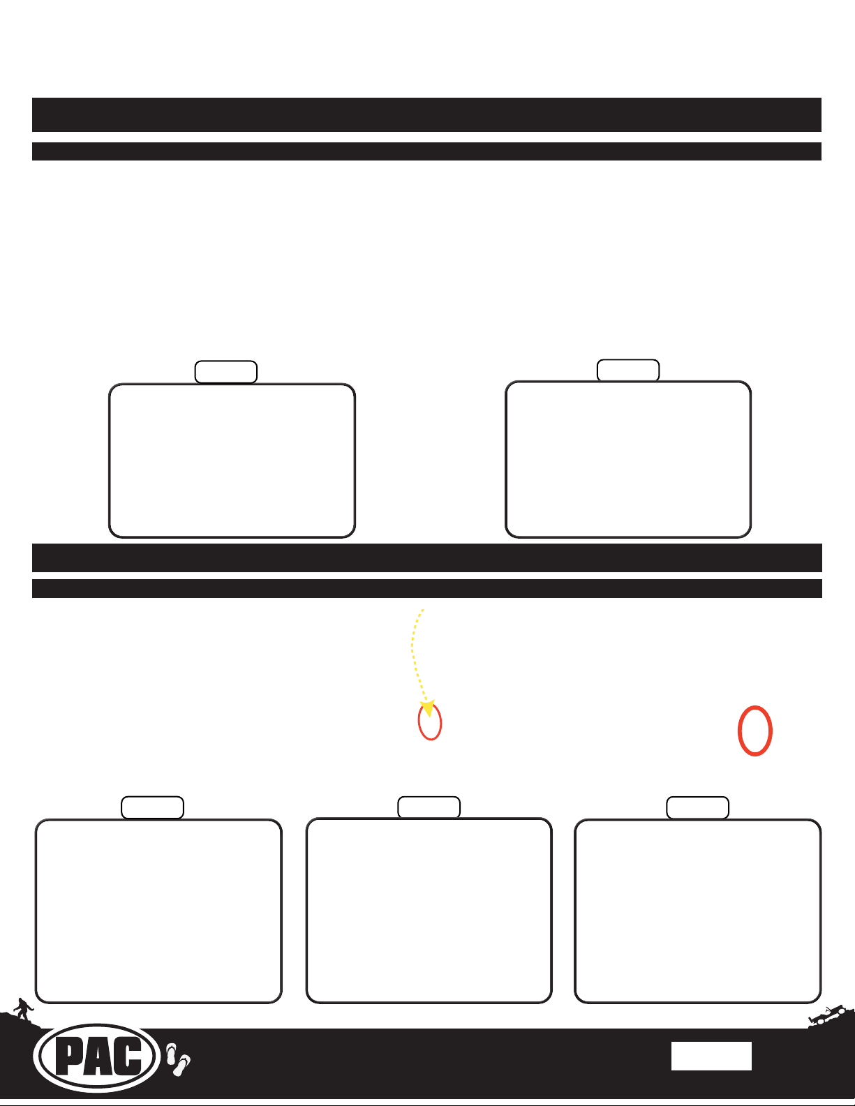
Part Five: AM / FM Antenna Adapter and RPA-HD1
Note: You can also
place the RPA-HD1
into the cavity that
is below the radio
cavity behind the
climate control
panel on the right
side.
Step 1
Connect the AM/FM antenna
adapter (BAA22) to the antenna
with the white connector that was
disconnected from the factory
radio.
Section 5: Radio Unit Installation
Part One: Harness and Cabling Connections
Step 2
Connect the factory camera cable
with an orange or red Fakra
connector into the Cam 1 port on
RPA-HD1, then slide the RPA-HD1
through the radio opening into the
cavity behind the dash that is above
the center left air vent or into the
cavity behind the right side of the
climate control mounting area.
Step 1
Before attempting to mount the
radio unit into the dash, rst
ensure that all excess cables and
wires are tucked into the sides,
out of the way of the radio. The
radio unit is a snug t and will be
dicult to mount into the dash if
there is anything taking up space
behind the radio opening.
Step 2
Disconnect the two 4-pin
connectors on the RPKJW18-HAR, then connect the
MALE 4-pin connector on the
MQS4PT-36 harness into the
FEMALE 4-pin connector on the
RPK-JW18-HAR. The MALE
4-pin connector on the RPK-
JW18-HAR will no longer be
used.
Step 3
Connect the 2-pin chime speaker
connector to the main harness.
Rev: v3
Date:100620
Page 12
Page 13
Stinger ELEV8 or HEIGH10® Radio Replacement Kit
for Jeep Wrangler JL and Jeep Gladiator JT Vehicles
SRK-JW18EH
© 2020 AAMP Global. All rights reserved. PAC is a Power Brand of AAMP Global.
AAMP Global is not aliated with FCA US LLC. Jeep® is a registered trademark of FCA US LLC. The terms
OEM, Jeep®, Wrangler®, and Gladiator® all terms are used strictly for identication purposes only. It is not
implied that any part listed is a product of, or approved by, Fiat Chrysler Automobiles.
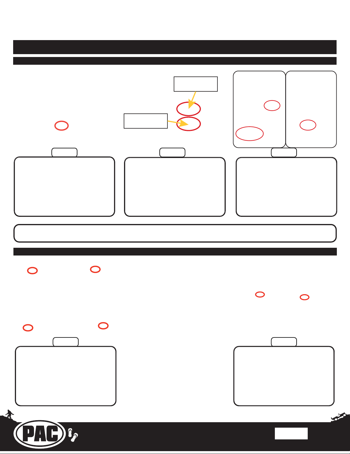
Gray
USB-UN1
adapter cable
Black center console
USB-UN2
adapter cable
1
2
5
3
4
Section 5: Radio Unit Installation (cont.)
Part One: Harness and Cabling Connections (cont.)
Step 4
Connect the 10P-2-10P-18
connector coming from the RPA-
HD1 interface module into the
open port on the PL1 interface
module, then connect the 52-pin
dock-and-lock connector to the
main OEM radio connector in the
vehicle.
Step 5
Connect the USBs into the
appropriate ports on the Stinger
radio module. Ensure that the
USB-UN1 is connected to port 1,
and the center console USB-UN2
is connected to port 2.
Connect the AM/FM antenna (3),
the HDMI cable (4), and the GPS
Step 6
antenna (5).
For a complete wiring diagram overview, refer to page 2.
Part Two: Radio Unit Mounting
Note: Once the radio unit is
slid into the radio cavity, the kit
will not always seat fully into
the dash. There is sometimes
about a 1/4-inch gap between
the screw holes. If the previous
steps of the instructions were
followed, this 1/4-inch gap will
close with the tightening of the
While holding the cabling above
the vents in the dash, slide the
radio unit into the radio cavity and
secure it to the dash using the
four 7mm screws that held the
factory radio in place.
four 7mm screws, allowing the kit
to seat fully into place. If there is
more than a 1/4-inch gap before
installing the screws, slide the
radio unit back out and readjust
the connectors and cables behind
the radio opening until they are no
longer in the way of the radio unit,
then reinstall.
Connect the Stinger display
cables into the back of the
Stinger radio display and secure
it to the radio unit mounting
bracket against the dash using
the orange clips and the two 7mm
screws below the radio cavity.
Step 2Step 1
Rev: v3
Date:100620
Page 13
Page 14
Stinger ELEV8 or HEIGH10® Radio Replacement Kit
for Jeep Wrangler JL and Jeep Gladiator JT Vehicles
SRK-JW18EH
© 2020 AAMP Global. All rights reserved. PAC is a Power Brand of AAMP Global.
AAMP Global is not aliated with FCA US LLC. Jeep® is a registered trademark of FCA US LLC. The terms
OEM, Jeep®, Wrangler®, and Gladiator® all terms are used strictly for identication purposes only. It is not
implied that any part listed is a product of, or approved by, Fiat Chrysler Automobiles.
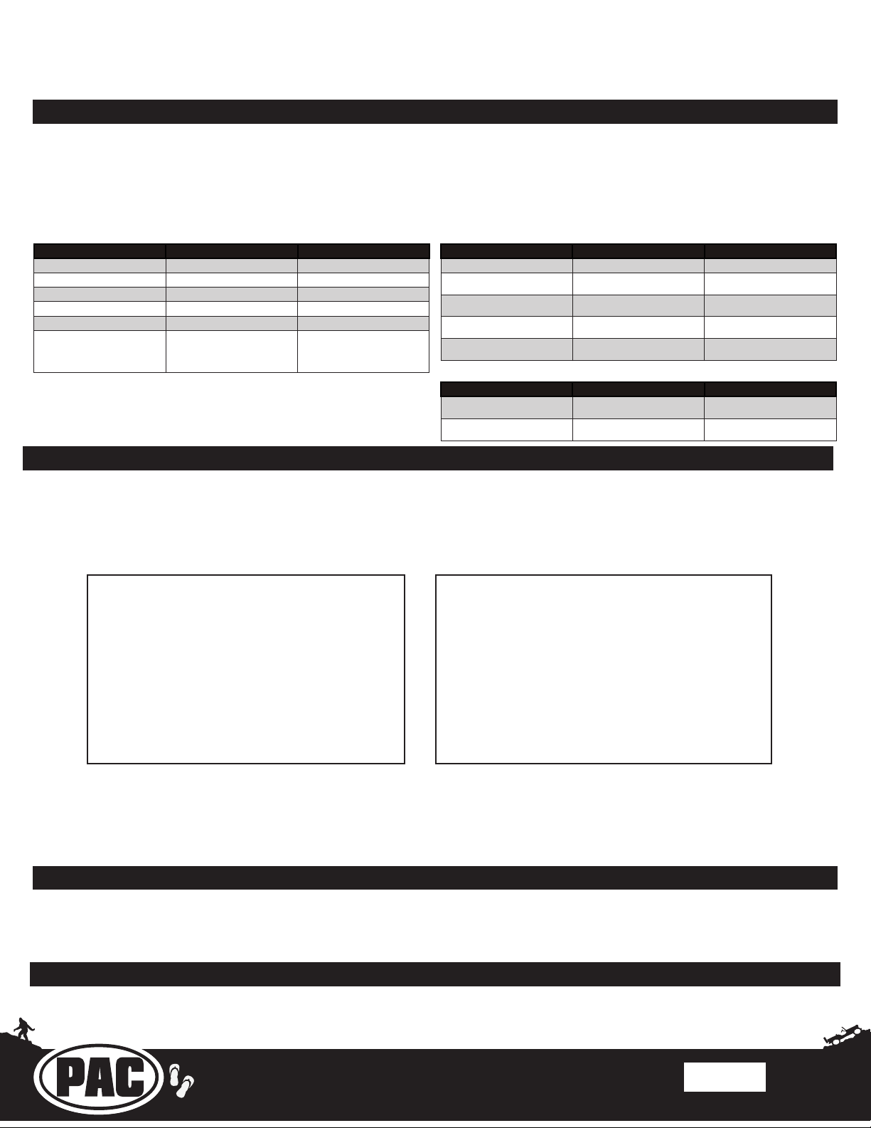
Troubleshooting
1. Reverse camera inoperable - Verify that all reverse camera wiring connection points are proper by reviewing the RPA-
HD1 connection steps.
2. Vehicle Info icon not showing on main menu - After updating the Radio System Firmware, perform a master reset on
the radio by tapping “Master Reset” in the “Installer Settings”; then, update the PAC Application APK rmware in that order.
If the Vehicle Info icon still does not show, turn o the vehicle, open the driver door, and let it sleep for about 20 seconds,
then restart the vehicle and check for the Vehicle Info icon again.
CH4A-JW18 Interface Module LED Diagnostics
LED Pattern State Action
LED 2 solid red Vehicle RAP / ACC Output Is On N / A
LED 2 ashing green SWC Activity N / A
LED 2 ashing red Module Resetting / Initializing N / A
LED 1 solid green Module Powered and Operating N / A
LED 1 ashing amber USB Connected N / A
Verify key is in ignition position.
O No Activity
Verify that there is 12v on the
yellow wire and ground on the
black wire.
RPA-HD1 Camera Module LED Diagnostics
LED Pattern State Action
LED solid red Initial Power-Up N / A
LED ickering green Querying RadioPro for Congu-
LED ashing green Normal Operation w/ HDMI
LED solid amber Normal Operation w/ Camera
O No Activity Verify 10pin harness connections
ration
Pass-thru
selected
N / A
N / A
N / A
and key position
PL1 Adapter Module LED Diagnostics
LED Pattern State Action
LED ickering green or red Data Communication / Normal
O No Activity Verify 10pin harness connections
Operation
N / A
and key position
Product Updates (Firmware)
Firmware Updates (RadioPRO, PL1, HD1 Interface Modules)
The RadioPRO PC app will allow you to update the interface modules with new rmware as it becomes available. Please visit
www.PAC-audio.com/rmware to download available updates.
To update an interface module, open the RadioPRO PC app, connect the interface to your PC via a micro USB cable, and select
”Firmware” and then “Update Firmware”.
Now, select “Select File”. Finally, browse to the place where you saved the le, and select it. This will begin the updating
process. Once nished, disconnect the interface from the PC. Repeat for every module: CH4A, PL1, HD1, and test operation.
Firmware Updates (Stinger Radio and PAC Application APK)
To update the Stinger radio rmware and PAC Application APK rmware, refer to the Installer Setup Manual for an in-depth
walk-through on how to perform these updates on your Stinger radio unit.
Reset / Restoring Interface Factory Settings
You can restore the RadioPRO interface module to factory default settings by pressing and holding the programming button
on the side of the module until the status LED starts blinking red. Once the LED starts blinking red, release the button. You
must release the button while the LED is blinking red in order to perform the reset. This reset will restore all settings to factory
defaults.
Technical Support
Email: [email protected]
Phone: 866-931-8021
International: 727-592-5991
Rev: v3
Date:100620
Page 14
 Loading...