

Page 1
MC2 Power Systems
User's Guide
November 2006
Document ID 1110227 Revision 2
Page 2

Copyright notice
Copyright © 2006 Stinger Medical, LLC. All rights are reserved. The software in this
product is protected by applicable United States of America copyright laws and
international treaty provisions.
Publication date
November 2006
Printed in U.S.A.
Product and version
MC2 Power Systems
Stinger document control number
Document ID 1110227 Revision 2
Reader comments
Any comments or suggestions regarding this manual are welcomed and should be emailed to:
StingerDocumentation@stingermedical.com
Trademarks
Stinger, Stinger Medical, LLC, the Stinger Medical logo, MC2 Power System, the MC2
Power System logo and Stinger Mobile Computer Workstation are trademarks of Stinger
Medical. Windows is a registered trademark of Microsoft Corporation in the United States
and/or other countries. All other product and company names herein may be tradema rks,
service marks, or registered trademarks of their respective companies.
Disclaimers
Stinger Medical, LLC provides the following cautions to the reader of this manual:
• Stinger Medical, LLC may change all or part of this manual without notice.
• All rights are reserved. Reproduction or duplication of all or part of this manual, in any
form, is prohibited without the explicit written permission of Stinger Medical, LLC.
• Stinger Medical, LLC assumes no responsibility for damage or injury from use of the
MC
Contact information
• Stinger Medical Technical Support 888-445-8970
• Stinger Medical Sales 888-445-8970
• Web site address
2
Power System not in accordance with the instructions provided in this manual.
http://www.stingermedical.com
1110227 Revision 2
ii November 2006
Page 3

MC2 Power Systems User's Guide Table of Contents
Table of Contents
About This Document.................................................................................................................v
Overview............................................................................................................................. v
Document Conventions.......................................................................................................vi
Intended Use .............................................................................................................................vii
Product Safety Information.....................................................................................................viii
Safety Guidelines..............................................................................................................viii
Warning Labels and Symbols...................................................................................................ix
Warning Symbols................................................................................................................ix
Warning Labels................................................................................................................... x
EMI (Electromagnetic Interference) Information .......................................................... x
Obtaining Optimum Performance .......................................................................................xi
Chapter 1: Quick Setup ..............................................................................................................1
Chapter 2: 26 Amp-Hour Series.................................................................................................5
Identifying The Power System............................................................................................5
Preparing For Operation.....................................................................................................6
User-Selectable Switch Settings.........................................................................................9
Chapter 3: 35 Amp-Hour Series...............................................................................................11
Identifying The Power System..........................................................................................11
Preparing For Operation...................................................................................................13
User-Selectable Switch Settings.......................................................................................15
Chapter 4: Identifying Fuel Gauge Indicators ........................................................................17
Chapter 5: Charging the Power System .................................................................................19
Chapter 6: Power System Management Software .................................................................21
Installing the Advanced Power Monitor Software............................................................. 22
Configuring Advanced Power Monitor Access Options....................................................24
Configuring COM Ports.....................................................................................................25
Understanding the Advanced Power Management Software........................................... 27
Chapter 7: Troubleshooting.....................................................................................................29
Reset Procedures....................................................................................................... 30
Charger Timed-out Reset Procedure.........................................................................30
Chapter 8: Preventative Maintenance.....................................................................................33
Chapter 9: Service and Support ..............................................................................................35
Chapter 10: Battery Disposal...................................................................................................37
November 2006 1110227 Revision 2 iii
Page 4

Table of Contents MC2 Power Systems User's Guide
Appendix A: Power System Specifications............................................................................39
Appendix B: Mechanical Specifications.................................................................................41
Appendix C: Power System Specifications............................................................................43
Appendix D: System Electromagnetic Emissions and Immunity Declarations..................45
Glossary.....................................................................................................................................51
1110227 Revision 2
iv November 2006
Page 5

MC2 Power Systems User's Guide About This Document
About This Document
Overview
The MC2 Power System was designed specifically to meet the needs of point-of-care
mobile solutions. This document contains all the essential information necessary to use
and maintain the MC
and future success of your power system, there are a few key points to keep in mind:
• Establish clinical protocols for plugging in the power system to charge whenever it is
not in use to ensure uninterrupted clinical workflow.
• Use only Stinger Medical-approved peripherals with the power system.
2
• The MC
Power System has no user-serviceable internal parts.
2
Power System at its maximum potential. To ensure the current
1110227 Revision 2
November 2006 v
Page 6
About This Document MC2 Power Systems User's Guide
Document Conventions
The following conventions are used throughout this document:
Convention Description
Keyboard keys and
function keys
Key combinations Are enclosed in brackets and appear in bold type
Execution buttons
Menu names and options
Window names
Text variables Are enclosed in angle brackets; for example, <drive name>.
Numeric variables Are represented by a letter; for example, x.
Begin with an uppercase letter and appear in bold type, enclosed in
brackets; for example, [Enter] or [F1].
If joined with a plus sign (+), press and hold the first and second key
simultaneously; for example, Press [Ctrl+B].
Begin with uppercase letters and appear in bold type, for example,
OK.
Begin with uppercase letters and appear in bold type; for example, On
System Setup menu, click Restore Factory Profile.
the
Begin with uppercase letters and appear in bold type; for example, the
Advanced Power Monitor Software Setup window is displayed.
In addition, the following special formats are used:
Format Indicates…
Green text
Courier
a hyperlink to another section of this document or to a web site
text of a message displayed in a window
Courier bold text that you must type in a window
Bold
Italics a reference to another document; also indicates emphasis on certain
a reference to a window or to an object in a window, such as a button,
field, or column; also indicates emphasis on a critical instruction or
step
words (Example: do
not delete this file)
vi November 2006
1110227 Revision 2
Page 7

MC2 Power Systems User's Guide Intended Use
Intended Use
The Stinger Medical workstations and power systems are intended for the continuous
non-invasive logging of patient data in hospitals, hospital-type facilities, and intra-hospital
transport.
Note:
Hospital use typically covers such areas as ge neral care floors, operating rooms,
special procedure areas, intensive and critical care areas within the hospital-type
facilities. Hospital-type facilities include physician office-based facilities, sleep labs,
skilled nursing facilities, surgical centers, and sub-acute centers.
Intra-hospital transport includes transport of patient within the hospital or hospital-type
facility.
Medical and non-medical apparatus such as vital signs monitors, computers, LCD
monitors and bar-code scanners may be supplied by Stinger Medical or may be
configured locally. The collateral standard for medical electrical systems, IEC 60601-1-1
Second Edition 2000-I2, provides requirements for integrating ITE, such as a printer or
monitor, with medical equipment.
Information in this document has been carefully checked for accuracy; however, no
guarantee is given to the correctness of its contents. This document is subject to change
without notice. Stinger Medical provides this information as reference only.
Stinger Medical
1152 Park Avenue
Murfreesboro, TN 37129
888-445-8970 – Toll free
615-896-1652 – Phone
615-896-8906 – Fax
http://www.stingermedical.com
November 2006 vii
1110227 Revision 2
Page 8

MC2 Power Systems User's Guide Product Safety Information
Product Safety Information
Safety Guidelines
The MC² Power System Series™ is designed to ensure both the highest level of product
quality and safety for the user. To maintain both quality and safety, follow the guidelines
and instructions in this manual.
• Use the power system only as intended.
• Do not place the power system near a window. Exposing the power system to rain,
water, moisture, or constant, direct sunlight can severely damage it.
• To maintain your warranty, refer all servicing to Stinger Medical qualified personnel.
The MC² Power System has no user-serviceable, internal parts.
• Do not cover or obstruct any venting holes on the power system.
• Store the power system within 10 to 30 degrees Celsius (50 to 86 degrees
Fahrenheit). Storing the system outside the temperature range could result in
permanent damage.
• Use and maintain the cord set provided with the unit.
• If any cord or cable is frayed or damaged, replace it immediately with another of the
same type and rating as supplied by Stinger Medical.
• To clean the exterior of the power system, follow the UL 60601-1 standard for use in
a hospital environment. See “
• Before cleaning the 26 Amp-Hour unit, disconnect the electronic and power
enclosures from their power sources.
• Before cleaning the 35 Amp-Hour unit, disconnect the electronic enclosure from its
power source.
Cleaning Procedures” for more information.
November 2006 viii
1110227 Revision 2
Page 9
MC2 Power Systems User's Guide Warning Labels and Symbols
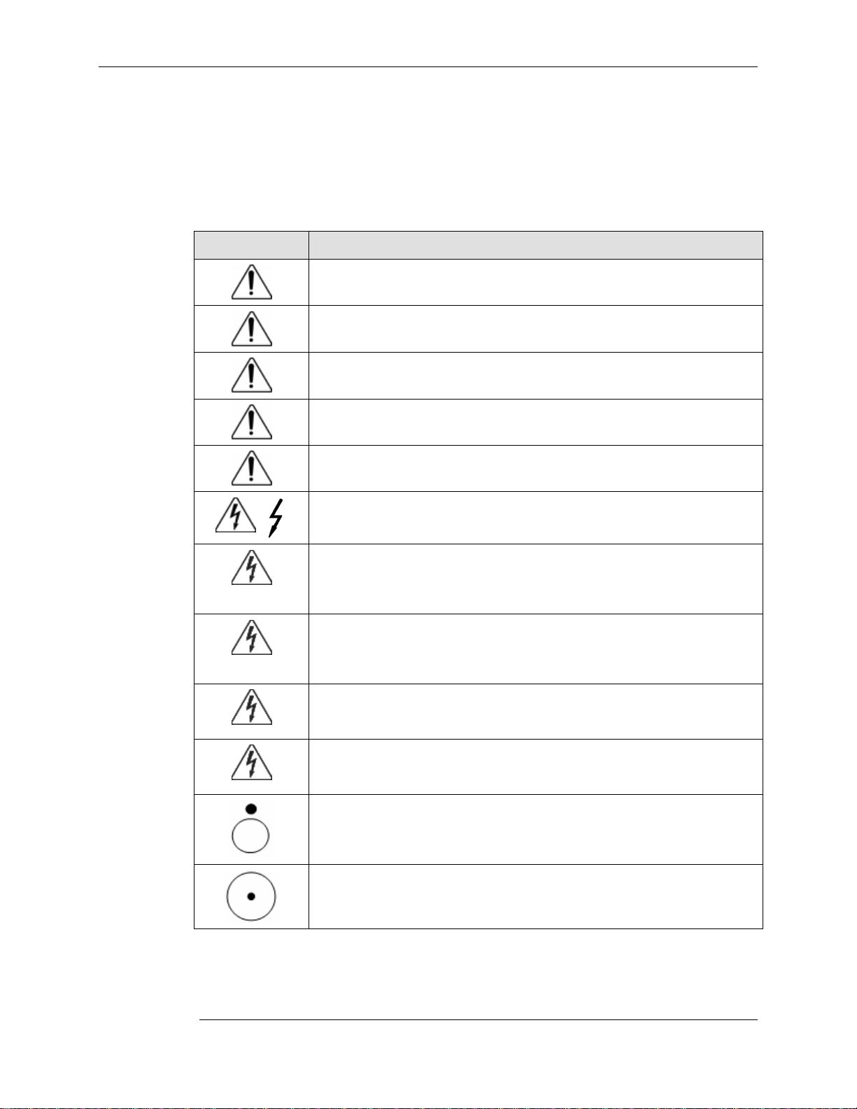
Warning Labels and Symbols
Warning Symbols
Symbol Description
THIS SYMBOL ALERTS OF AN IMPENDING DANGER. Failure to follow
instructions could result in personal injury and/or damage to the unit.
USE A NONFLAMMABLE CLEANER WHEN CLEANING THE UNIT! Failure
to do so can result in death, explosion, and/or fire.
DO NOT LEAVE THE UNIT UNATTENDED AROUND CHILDREN! Failure to
do so can result in injury, and/or death.
CAUTION: THE POWER SYSTEM IS HEAVY. You must use proper lifting
techniques. Failure to do so can result in injury.
AVOID USING AN EXTENSION CORD WITH THE UNIT! If an extension
cord must be used, ensure it is rated for the power capacity of the unit.
THIS SYMBOL ALERTS OF IMPENDING ELECTRICAL HAZARD. Failure to
follow instructions could result in personal injury, fire and/or death.
DO NOT OPEN THE POWER SYSTEM! Unauthorized personnel opening the
power system may cause injury and/or death. If the unit is not working
properly, please contact the Stinger Medical C.A.R.E. department at 888-4458970
DO NOT USE THE UNIT IN/NEAR WATER OR OTHER LIQUIDS! If the unit
becomes wet, unplug it immediately, wipe away any excess liquid and al low it
to dry before use. Failure to do so may cause electric shock, damage to the
unit, voiding of warranty, injury or death.
DO NOT IMMERSE THE POWER SYSTEM IN WATER! This is an electrical
hazard and can cause damage to the unit, void product warranty and could
result in personal injury, fire and/or death.
ALWAYS KEEP THE UNIT WELL VENTILATED! Do not block ventilation
airways or insert items into the ventilation slots. Failure to do so can cause
the power system to overheat and possibly cause fire, explosion, and/or death.
“Off” (only for a part of EQUIPMENT) IEC Publication #417-5265
“On” (only for a part of EQUIPMENT) IEC Publication #417-5264
November 2006 ix
1110227 Revision 2
Page 10
Warning Labels and Symbols MC2 Power Systems User's Guide
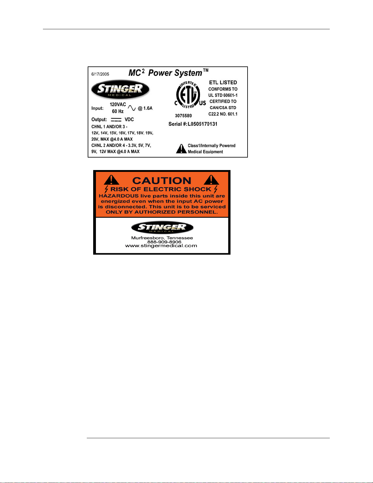
Warning Labels
EMI (Electromagnetic Interference) Information
Portable and mobile RF communications equipment can affect Medical Electrical
Equipment. This equipment should not be used adjacent to or stacked with other
equipment. If adjacent or stacked is necessary, this and other equipment should be
observed to verify normal operation in the configuration in which it will be used.
These limits are designed to provide reasonable protection against harmful interference
in a residential installation. This equipment generates, uses, and can radiate ra dio
frequency energy, and if not installed and used in accordance with the instruction
manual, may cause interference to radio communications. However, there is no
guarantee that interference will not occur in a particular installation. If this equipment
does cause harmful interference to radio, television or Medical Electrical Equipment
reception, which can be determined by turning the equipment off and on, the user is
encouraged to try to correct the interference using one or more of the following
measures: reorient or relocate the receiving antenna; increase the separation between
the equipment and the receiver; connect the equipment into an outlet on a circuit different
from that which the receiver is connected; consult the dealer or an experienced
radio/television technician for help. The user must use shielded cables and connectors
with this product. Any changes or modifications to this product not expressly approved by
the party responsible for compliance could void the user’s authority to operate the
equipment. Operation is subject to the following two conditions: (1) This device may not
cause harmful interference, and (2) This device must accept any interference received,
including interference that may cause undesired operation. MC
exceeds FCC Class A limits for EMI.
2
Power System meets or
1110227 Revision 2
x November 2006
Page 11

MC2 Power Systems User's Guide Warning Labels and Symbols
Obtaining Optimum Performance
• Plug your MC² Power System into an AC power source (wall outlet) for charging
whenever not in use or unattended.
• Stinger Medical recommends establishing a protocol for end users requiring the
power system be plugged into and AC power source whenever not in use or
unattended.
• Perform regular preventative maintenance. Failure to do so will void warranty.
• Limit current output to 4 amps per channel.
• Do not open power system enclosure – there are no user-serviceable parts inside.
Opening enclosure will void product warranty.
November 2006 xi
1110227 Revision 2
Page 12

Page 13
MC2 Power Systems User's Guide Chapter 1: Quick Setup
Chapter 1: Quick Setup
Note:
The quick setup information in this chapter pertains to both the 26 Amp-Hour and 35
Amp-Hour units.
Use the references in the following table to obtain further information about your unit to
assist you during the set up process:
MC2 Power System See page
26 Amp-Hour Unit
Identifying the Power System
Preparing for Operation
User-Selectable Switch Settings
35 Amp-Hour Unit
Identifying the Power System
Preparing for Operation
User-Selectable Switch Settings
If the power system unit was sent alone:
1 Unpack the power system unit and check for any physical damage.
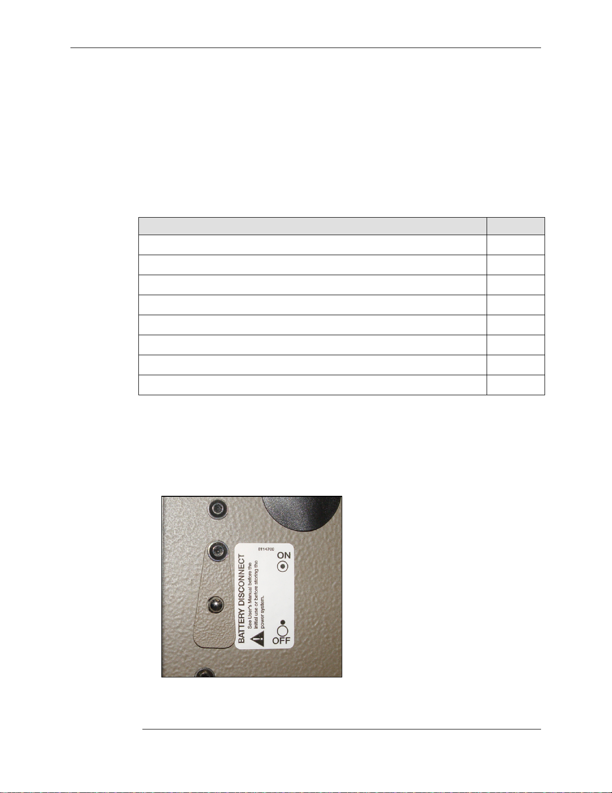
2 For the MC2 Power System Series 26 Amp-Hour units, connect and secure the
electronic and battery enclosure together. For the MC
Amp-Hour units, the Power Output Disconnect Switch (depicted below) must be in
the ‘ON’ position:
5
6
9
11
13
15
2
Power System Series 35
Power output disconnect switch location
3 Verify that all LED indicators for each power output channel are ON.
November 2006 1
1110227 Revision 2
Page 14
MC2 Power SystemsChapter 1: Quick Setup User's Guide
4 Output voltages are normally pre-configured to power on the intended device(s) prior
to shipping. Check the user-selectable switch settings to verify that the correct
voltage has been set for each power output channel.
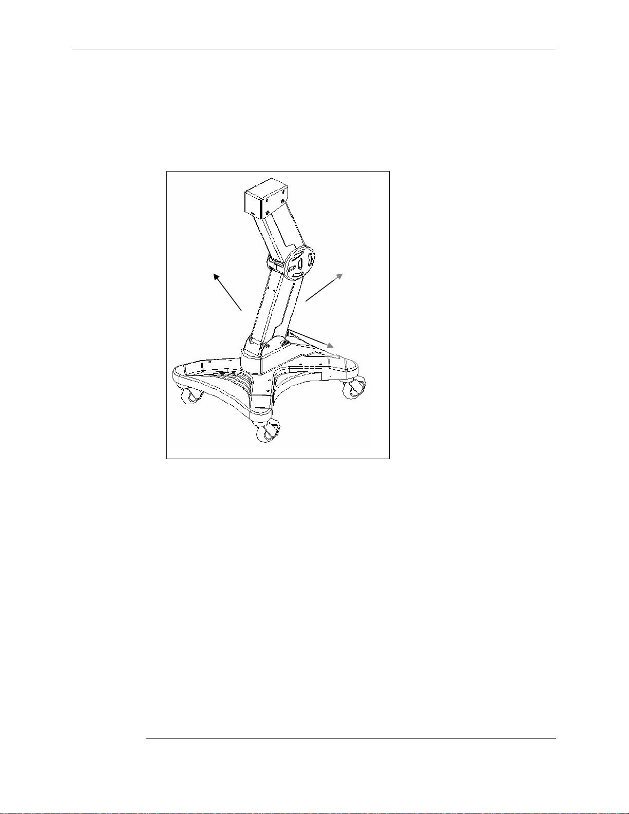
5 Locate the power output plastic cover on the back side of the base. Remove the
power output plastic cover and slide the power system unit into base of the cart.
Secure the power system unit with the two security pins located on both sides of the
base (Fig 1):
Security
Pin
Output
Plastic
Cover
Security
Pin
Power
Fig 1: Location of plastic cover and pins
6 Check all existing power and data cables on the cart for any visible defects.
7 Connect each power cable to the configured power output channel for the intended
device. Laptop computers are usually connected to the Power Output 1 located on
the far left-hand side.
8 If available, connect the USB and fuel gauge cables to the power system unit.
9 Plug in the power system unit to charge and verify that one or more LED indicators
on the fuel gauge is working properly.
10 Assemble and secure the power output plastic cover onto the cart.
11 Plug in the power system unit to charge prior to use. For optimal charging
performance, charge the unit with no devices ON.
12 Check fuel gauge to verify that the LED indicators for both ‘AC Present’ and
‘Charging’ are ON.
13 The power system unit is ready for use when LED indicator for ‘Charged’ is ON.
14 Connect the correct power cable to each device. Verify that the correct power cable
is being used for the intended device since each power output can be configured to
different voltages.
1110227 Revision 2
2 November 2006
Page 15

MC2 Power Systems User's Guide Chapter 1: Quick Setup
15 Power ON device(s).
If power system unit was sent with a workstation:
1 Check the power system unit and workstation for any physical damage.
2 For the MC2 Power System Series 35 Amp-Hour units, the Power Output Disconnect
Switch must be in the ‘ON’ position.
3 Verify that all LED indicators for each power output channel are ON.
4 Output voltages and power cables are normally pre-configured to power on the
intended device(s) prior to shipping. Check the user-selectable switch settings to
verify that the correct voltage has been set for each power output channel.
5 Locate the power output plastic cover on the back side of the base. Remove the
power output plastic cover and verify that all cables have no physical defects and are
properly secured to each power output channel (Fig 2):
Power
Output
Plastic
Cover
Fig 2: Location of plastic cover
6 Plug in the power system unit to charge and verify that one or more LED indicators
on the fuel gauge is working properly.
7 Assemble and secure the power output plastic cover onto the cart.
8 Plug in the power system unit to charge prior to use. For optimal charging
performance, charge the unit with no devices ON.
9 Check fuel gauge to verify that the LED indicators for both ‘AC Present’ and
‘Charging’ are ON.
10 The power system unit is ready for use when LED indicator for ‘Charged’ is ON.
1110227 Revision 2
November 2006 3
Page 16

Chapter 1: Quick Setup MC2 Power Systems User's Guide
11 Connect the correct power cable to each device. Verify that the correct power cable
is being used for the intended device since each power output can be configured to
different voltages.
12 Power ON device(s).
1110227 Revision 2
4 November 2006
Page 17
MC2 Power Systems User's Guide Chapter 2: 26 Amp-Hour Series
Chapter 2: 26 Amp-Hour Series
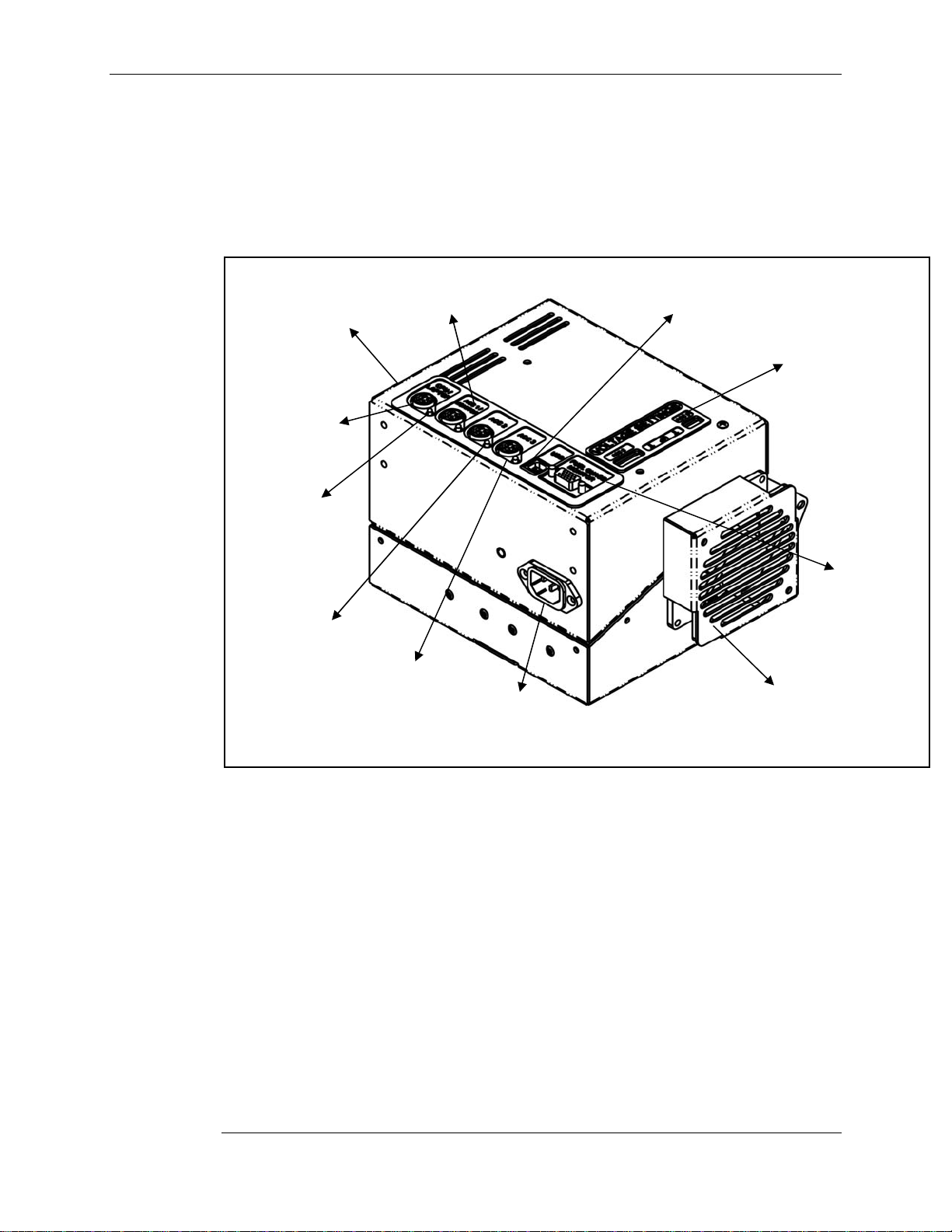
Identifying The Power System
Voltage Settings for
CPU/Laptop & ACC
1/Monitor Power
Outputs
(shown left side)
CPU/Laptop
Power Output
LED Power
Indicator
ACC 2 Power
Output
ACC 1/ Monitor
Power Output
ACC 3 Power
Output
120V 60Hz AC
Power Input
Power Management
Software Connect
(USB Type B)
Voltage
Settings for
ACC 2 & ACC
3 Power
Outputs
(optional)
Fuel Gauge
Monitor
Connect
Cooling Fan
Exhaust
Fig 6: Identifying the Electronic Enclosure
Notes:
• ‘ACC’ is an abbreviation for ‘Accessory’.
• Sticker for voltage settings ACC 2 and ACC 3 will not be present if only two
outputs are purchased.
• LED for ACC 2 and ACC 3 will not be functional if only two outputs are
purchased.
1110227 Revision 2
November 2006 5
Page 18
Chapter 2: 26 Amp-Hour Series MC2 Power Systems User's Guide
Preparing For Operation
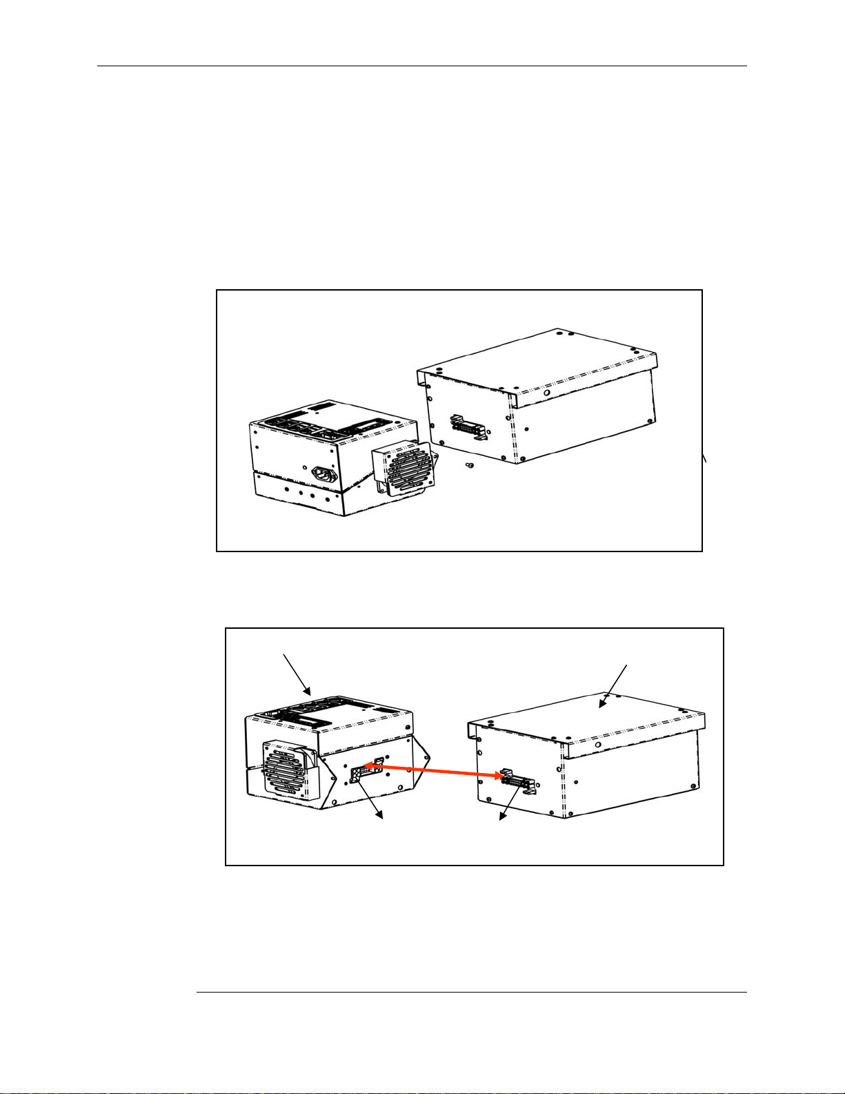
Parts Listing (Fig 7)
• (1) Electronic Enclosure (A)
• (1) Battery Enclosure (B)
• (1) Cord Set (Fig 10 and 11)
1 Unpack the unit carefully and inspect it for damage. There will be two parts -
Electronic Enclosure and Battery Enclosure. WARNING: Battery enclosure is
HEAVY!
Fig 7: MC2 Power System Parts
Electronic Enclosure (A)
Battery Enclosure (B)
2 Connect electronic enclosure (A) and battery enclosure (B) at docking connector (Fig
8).
Electronic Enclosure (A)
Docking Connector 1
Docking Connector 2
Battery Enclosure (B)
Fig 8: Docking Connection
3 Install security screws (C) with security wrench (included).
1110227 Revision 2
6 November 2006
Page 19

MC2 Power Systems User's Guide Chapter 2: 26 Amp-Hour Series
Security Screw (C)
Fig 9: Security Screw Installation
4 Confirm the green LED power indicators light up beside the outputs.
Note:
Number of LEDs to light up will vary based upon the number of outputs
purchased.
5 Charge your MC² Power System using a Stinger Medical supplied cord set (Fig 10
and 11) for 24 hours prior to use. For more information, see “
System
Fig 10: Curly Cord
”.
Charging the Power
1110227 Revision 2
November 2006 7
Page 20
Chapter 2: 26 Amp-Hour Series MC2 Power Systems User's Guide
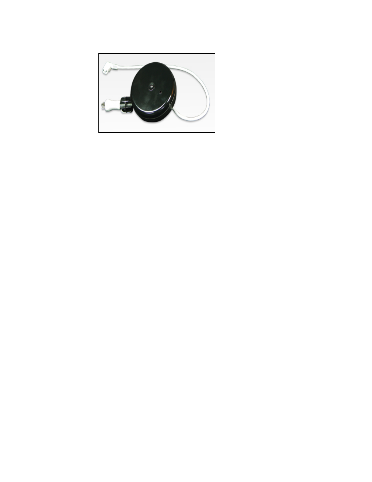
Fig 11: Cord Reel
6 Confirm the ‘Charging’ indicator on the fuel gauge is ON. For more information, see
Identifying Fuel Gauge Indicators”.
“
7 Your Power System is ready for use when the ‘Charged’ indicator is ON.
1110227 Revision 2
8 November 2006
Page 21

MC2 Power Systems User's Guide Chapter 2: 26 Amp-Hour Series
User-Selectable Switch Settings
Voltage Settings Orientation
• The diagram below shows each switch location and which output it controls.
• The output voltage can be set by user between 12–20V on outputs ‘CPU/Laptop’ and
‘ACC 2 (optional)’ and between 3.3 – 12V on outputs ‘ACC 1/Monitor’ and ‘ACC 3
(optional)’.
• All outputs have a maximum continuous current of 4 amps.
• User-selectable switches are located on the top and side of the electronic enclosure
(Fig 12).
• Power outlets are intended for workstation mounted equipment ONLY.
CPU/Laptop & ACC 2 Power Settings ACC 1/Monitor & ACC 3 Power Settings
Fig 12: Location of User-selectable Switches
Voltage Settings for
CPU/Laptop & ACC
1/Monitor Power
Outputs
Voltage
Settings for
ACC 2 & ACC
3 Power
Outputs
(optional)
1110227 Revision 2
November 2006 9
Page 22

Chapter 2: 26 Amp-Hour Series MC2 Power Systems User's Guide
1110227 Revision 2
10 November 2006
Page 23

MC2 Power Systems User's Guide Chapter 3: 35 Amp-Hour Series
Chapter 3: 35 Amp-Hour Series
Identifying The Power System
LED
Power
Output 1
Power
Output 2
Power
Indicator
Fuel Gauge
Monitor Connect
Top view
Fig 13: Power Output Port Connectors
Power
Output
3
Power
Output 4
Power
Management
Software
Connect
(USB Type B)
November 2006 11
1110227 Revision 2
Page 24

Chapter 3: 35 Amp-Hour Series MC2 Power Systems User's Guide
Right-hand view
Cooling Fan
Fig 14: Fan and Power Output Disconnect Switch
Rear view
120V 60Hz AC
Power Input
Fig 15: AC Power Input
Power Output Disconnect Switch:
↑ ON
↓ OFF
1110227 Revision 2
12 November 2006
Page 25

MC2 Power Systems User's Guide Chapter 3: 35 Amp-Hour Series
Preparing For Operation
Parts Listing
•
(1) Power system unit (Fig 16)
•
(1) Cord Set (Fig 17 and 18)
Fig 16: MC2 Power System Series 35 Amp-Hour
1 Unpack components carefully, inspecting for damage. WARNING: Power System is
HEAVY!
2 Confirm that the Power Output Disconnect Switch is in the ‘ON’ position. For more
information, see “
Identifying the Power System.” Verify that the green LED power
indicators light up beside the outputs.
Note:
The number of LEDs to light up will vary based upon the number of outputs
purchased.
3 Charge your MC² Power System using a Stinger Medical supplied cord set (Fig 17
and 18) for 24 hours prior to use. For more information, see “
System
Fig 17: Curly cord Fig 18: Cord reel
.”
Charging the Power
1110227 Revision 2
November 2006 13
Page 26

Chapter 3: 35 Amp-Hour Series MC2 Power Systems User's Guide
4 Confirm the ‘Charging’ indicator on the fuel gauge is ON (see “Identifying Fuel Gauge
Indicators
”).
5 Your Power System is ready for use when the ‘Charged’ indicator is ON.
1110227 Revision 2
14 November 2006
Page 27

MC2 Power Systems User's Guide Chapter 3: 35 Amp-Hour Series
User-Selectable Switch Settings
Voltage Settings Orientation
• The diagram below illustrates each switch location and which output it controls.
• The output voltage can be set by user between 12–20V on Power Output 1 and
Power Output 3 and between 3.3 – 12V on Power Output 2 and Power Output 4.
• All outputs have a maximum continuous current of 4 amps.
• User-selectable switches are located on the top and left hand side of the power
system enclosure.
• Power outlets are intended for workstation mounted equipment ONLY.
Power Output 1 and 3 Power Settings Power Output 2 and 4 Power Settings
Voltage Settings for Power
Output 1 and Power Output 2
Left hand view
1110227 Revision 2
November 2006 15
Page 28

Chapter 3: 35 Amp-Hour Series MC2 Power Systems User's Guide
Voltage Settings for Power Output 3
and Power Output 4 (optional)
1110227 Revision 2
16 November 2006
Page 29

MC2 Power Systems User's Guide Chapter 4: Identifying Fuel Gauge Indicators
Chapter 4: Identifying Fuel Gauge Indicators
Basic
Advanced
Press & hold 15
seconds to put
power system in
suspend mode
for storage (all
LEDs will not be
lit). Press
momentarily for
wake-up (3
seconds).
120V 60Hz
AC power
connected
Internal charger
error or battery
enclosure not
properly
connected.
Charge
mode
Power
system fully
charged
Power
system low
When blinking,
Fuel capacity
indicator
120V 60Hz AC
Power Connected
Note:
An alarm sounds when the system is fully discharged. To silence alarm, plug in the
unit to charge it.
November 2006 17
1110227 Revision 2
power system is
fully charged
and connected
to AC power
OR
When solid,
power system is
unplugged from
AC power and is
running on
battery power.
Power
system
low
Page 30

Chapter 4: Identifying Fuel Gauge Indicators MC2 Power Systems User's Guide
1110227 Revision 2
18 November 2006
Page 31

MC2 Power Systems User's Guide Chapter 5: Charging the Power System
Chapter 5: Charging the Power System
Note:
Where the integrity of the external PROTECTIVE EARTH CONDUCTOR
arrangement is in doubt, EQUIPMENT shall be operated from its INTERAL
ELECTRICAL POWER SOURCE.
Power System Charging
In order to charge the power system, plug it in to a 120V 60Hz AC power source using a
Stinger Medical supplied cord set.
Note:
2
Power System Series 35 Amp-Hour unit is required to have the Power
Charge Time
The MC
Output Disconnect Switch in the ON position. For more information, see the
Power Disconnect Output Switch Location” illustration.
“
Charge times vary depending on the usage of the power system. Typically, as a power
system is used, the capacity of the power system diminishes.
Charge time Cap acity of charge
6 hours with no load 100%
Optimal power system life occurs when unit is fully charged every cycle. For more
information, see “
Power System Discharging
The power system begins discharging when it is disconnected from the AC power source
and powering a peripheral device(s). After the power system reaches its maximum
runtime potential, it will disable power to its outputs. The MC² Power System Advanced
Monitoring System will communicate to the host computer and perform an orderly
shutdown of the Microsoft
power system for charging (Fig 19).
Fig 19: Low battery indicator
Identifying Fuel Gauge Indicators.”
®
Windows® Operating System unless the user plugs in the
November 2006 19
1110227 Revision 2
Page 32

Chapter 5: Charging the Power System MC2 Power Systems User's Guide
Circuit Protection
The MC² Power System is thermally protected and self-resetting. For more information,
No Output Reset Procedure.” The cooling fan maintains a constant ambient
see “
temperature inside the electrical enclosure.
Deep Discharge Protection
Deep discharge of the power system will significantly reduce its cycle life. After the
power to the load is disabled, the internal circuitry goes into suspend mode to prevent the
power system from reaching a level of deep discharge. To reduce this risk, the MC²
Power System will shut down and cut off the output voltage.
1110227 Revision 2
20 November 2006
Page 33

MC2 Power Systems User's Guide Chapter 6: Power System Management Software
Chapter 6: Power System Management Software
Setting Up the Power Management Software
• None – no USB cable provided – disregard this section.
• Advanced - available at time of purchase only – USB cable included.
• System Requirements: Operates ONLY on Windows XP and 2000.
Installation Note:
If the local computer has any type of anti-spyware or firewall application installed,
then you may receive a pop-up notice. To complete the installation process, enable
the program to be allowed to resume.
November 2006 21
1110227 Revision 2
Page 34

Chapter 6: Power System Management Software MC2 Power Systems User's Guide
Installing the Advanced Power Monitor Software
Note:
The Advanced Power Management Software is available for use with both the 26 AmpHour and 35 Amp-Hour units.
The Advanced Monitoring software does not offer the ability to perform an auto-run of the
software installation. Manual installation of the software is required to load the
application and the USB driver.
1 Navigate to the CD-ROM drive or the disk folder location where the installation files
reside.
2 Double-click the setup.exe file. The following window is displayed:
The following window is displayed:
3 Click OK. The following window is displayed:
1110227 Revision 2
22 November 2006
Page 35

MC2 Power Systems User's Guide Chapter 6: Power System Management Software
4 Click the installation button to begin installing the software:
The following window is displayed:
5 Accept the default Program Group, and then click Continue.
6 The installation is complete when the following window is displayed:
7 Click OK.
1110227 Revision 2
November 2006 23
Page 36

Chapter 6: Power System Management Software MC2 Power Systems User's Guide
Configuring Advanced Power Monitor Access Options
Creating a desktop icon to start the Advanced Power Monitor application
1 From the Start menu, point to All Programs, and then click Stinger Medical.
2 Right-click Advanced Power Monitor, and then click Copy.
3 Access the Windows desktop.
4 Right-click an empty location on the Windows desktop, and then click Paste.
Automatically starting the Advanced Power Monitor application
Perform the following steps to copy the Advanced Power Monitor application into the
Startup folder of each user on the computer:
1 From the Start menu, point to All Programs, and then click Stinger Medical.
2 Right-click Advanced Power Monitor, and then click Copy.
3 From the Windows desktop, double-click My Computer.
4 Double-click Local Disk (C:).
5 Double-click Documents and Settings.
6 Double-click All Users.
7 Double-click Start Menu.
8 Double-click Programs.
9 Double-click Startup.
10 Right-click in the Startup folder, and then click Paste.
11 Close all open windows.
1110227 Revision 2
24 November 2006
Page 37

MC2 Power Systems User's Guide Chapter 6: Power System Management Software
Configuring COM Ports
The Advanced Power Monitor software does not automatically determine which COM
port has been set for the communication between the computer and power system. The
user will have to manually determine what COM port has been assigned and manually
set it in the Advanced Power Monitor software by performing the following steps:
1 From the Start menu, point to Settings, and then click Control Panel.
2 Double-click System.
3 Click the Hardware tab.
4 Click Device Manager, depicted as follows:
5 Click the plus sign (+) by Ports (COM & LPT).
1110227 Revision 2
November 2006 25
Page 38

Chapter 6: Power System Management Software MC2 Power Systems User's Guide
6 Note the COM port assigned to the USB Serial Port, depicted as follows:
7 Launch the Advanced Power Monitor application.
8 Click Advanced Settings.
9 Click the down arrow in the COM Port field in Advanced Settings:
10 Select the COM port noted in step 6.
11 Click Minimize Settings to close the Advanced Settings options.
Communication between the computer and power system is successful when the
semicolon in the time clock is blinking off and on.
1110227 Revision 2
26 November 2006
Page 39

MC2 Power Systems User's Guide Chapter 6: Power System Management Software
y
Understanding the Advanced Power Management Software
Launch the Advanced Power Monitor application. The following window is displayed:
Calculated Time
Remaining
Fuel
Gauge
Green: Power system fully
charged
Yellow: Power system in a
low state of charge
Red: Warning – Power system
critically low – plug in to charge
immediatel
1110227 Revision 2
November 2006 27
Page 40

MC2 Power Systems User's Guide
November 2006 28
1110227 Revision 2
Page 41

MC2 Power Systems User's Guide Chapter 7: Troubleshooting
Chapter 7: Troubleshooting
The following table describes some of the most common troubleshooting options for the
2
power systems:
MC
Symptom Possible Cause Possible Solution
No output Re-settable fuse
Power system not charged Charge Power System
Reduced runtime Power system not charged Charge power system
Battery life exceeded
Component not powering Component not plugged in Plug in to power system
No output from power system
Dip switch incorrectly set
Power system section not
connected
Power output disconnect
switch in OFF position
No Output Reset
See “
Procedure
Connect both sections of
power system together (26
Amp-Hour unit only). See
Preparing for Operation.”
“
See “
in the MC
Series 35 Amp-Hour topic.
Contact Stinger Medical
C.A.R.E. department
See “
Procedure
26 Amp-Hour units: see
“
User-selectable Switch
Settings
units: see “
Switch Settings
”
Preparing for Operation”
2
Power System
No Output Reset
”
” OR 35 Amp-Hour
User-selectable
”
Power system not charged Charge power system
Overload
Power system beeping Power system discharged Plug in to charge
Not charging Faulty wall outlet Plug into alternate wall outlet
Faulty cord set Replace cord set (per policy)
Charger timed out
Battery life exceeded
1110227 Revision 2
November 2006 29
Contact Stinger Medical
C.A.R.E. department
Charger Timed-out
See “
Reset Procedure
Contact Stinger Medical
C.A.R.E. department
”
Page 42

Chapter 7: Troubleshooting MC2 Power Systems User's Guide
Symptom Possible Cause Possible Solution
No LEDs lit on power system
Re-settable fuse
COM port In use
Will not recognize USB
connection
Reset Procedures
No Output Reset Procedure
The Stinger Medical DC-to-DC circuit boards have been upgraded to self-resetting
polyfuses. If a situation occurs that could cause harm to a circuit, these fuses will trip and
protect the circuit from damage. The result of a tripped fuse is no output. Many reasons
could cause a fuse to trip. If a fuse is reset and the system continues to have a problem,
discontinue use of the system and contact the Stinger Medical C.A.R.E. department.
Below is an order of operation for resetting these fuses:
Power system not properly
connected
Battery in state of
unrecoverable discharge
USB not plugged in or
assigned COM port is used by
another device OR another
copy of the application is
running
Drivers not loaded
Power Output
See “
Disconnect Switch Location
Reconnect power system
sections (reference the
section of this document
specific to your power
system)
No Output Reset
See “
Procedure
Contact Stinger Medical
C.A.R.E. department
Contact Stinger Medical
C.A.R.E. department
See “ Installing the Advanced
Power Monitor Software
”
”
”
1 Remove all devices that are connected to the power system’s outputs.
2 Wait approximately 30-45 seconds after devices have been removed.
3 Insure that all devices are switched off, and then reconnect those devices.
4 Power on connected devices one at a time.
5 If fuse does not reset, repeat Steps 1-4 until fuse is reset.
If you continue to experience problems with the power system, discontinue use of the
system and contact the Stinger Medical C.A.R.E. department.
Charger Timed-out Reset Procedure
Note:
The following procedure is designed for use only with the MC
26 Amp-Hour Unit.
1 Remove all devices that are connected to the power system’s outputs.
2 Unplug AC power source.
3 Remove the power system from under the workstation.
1110227 Revision 2
30 November 2006
2
Power System Series
Page 43

MC2 Power Systems User's Guide Chapter 7: Troubleshooting
4 Remove the stabilizer plates and separate power system enclosures.
5 Wait 30 seconds.
6 Follow the steps listed in the MC
Preparing Your MC² Power System for Operation”.
“
2
Power System Series 26 Amp-Hour topic
7 Reconnect devices.
8 Plug in to charge until the fully charged notification light has illuminated.
If you continue to experience problems with the power system, discontinue use of the
system and contact the Stinger Medical C.A.R.E. department.
1110227 Revision 2
November 2006 31
Page 44

Chapter 7: Troubleshooting MC2 Power Systems User's Guide
1110227 Revision 2
32 November 2006
Page 45

MC2 Power Systems User's Guide Chapter 8: Preventative Maintenance
Chapter 8: Preventative Maintenance
Important note:
Please put the MC² Power System on a quarterly preventative maintenance schedule
to clean air intake filter(s). Failure to do so will void warranty.
Cleaning Procedures
When cleaning the MC² Power System, disconnect AC power source and se parate
electronic enclosure and battery enclosure. Refer to “
Procedure
clean the exterior of the power system. The following is a listing of approved cleaners
that are effective for cleaning the exterior of the power system:
• Quaternary ammonium chloride compounds (such as AirX 109®)
• Bleach – household strength (1:10 minimum dilution strength)
• Ethyl or Isopropyl alcohol – 70%
• Hydrogen Peroxide
• Phenolic Disinfectants (such as Lysol®)
• WexCide®
• Ovation®
• Fantastic®
• Formula 409®
• 1.6% Aqueous ammonia
• “Green Soap” USP (United States Pharmacopoeia)
” for separation instructions. Use a damp (slightly wet), mildly soapy cloth to
Charger Timed-out Reset
Cleaning the Filter Kit
The following instructions are recommended for cleaning the filter on the power system.
The filter kit is made up of three parts: finger guard, filter media, and retainer:
November 2006 33
Finger Guard
Filter Media
1110227 Revision 2
Page 46

Chapter 8: Preventative Maintenance
1 Remove the retainer from the finger guard on the power system.
2 Remove the filter media from the retainer.
3 Rinse the filter media thoroughly under cool running water.
4 Carefully squeeze excess water out of the filter media and lay the filter media flat to
dry.
5 Once the filter media is dry, replace it into the retainer.
6 Re-install the retainer onto the finger guard.
1110227 Revision 2
34 November 2006
Page 47

MC2 Power Systems User's Guide Chapter 9: Service and Support
Chapter 9: Service and Support
Should your power system or workstation require repair, contact the Stinger Medical
C.A.R.E. department to obtain an RMA (Return Merchandise Authorization). An RMA is
necessary to return the unit to Stinger Medical for servicing and to maintain the product
warranty. Any unit without an RMA will be returned at owner’s expense. See the
warranty for more information. Contact the Stinger Medical C.A.R.E department for
questions related to service and/or warranty coverage.
Stinger Medical C.A.R.E. Department
1152 Park Avenue
Murfreesboro, TN 37129
888-445-8970 – Toll free
615-896-1652 – Phone
615-896-8906 – Fax
http://www.StingerMedical.com
November 2006 35
1110227 Revision 2
Page 48

Chapter 9: Service and Support MC2 Power Systems User's Guide
1110227 Revision 2
36 November 2006
Page 49

MC2 Power Systems User's Guide Chapter 10: Battery Disposal
Chapter 10: Battery Disposal
Industrial batteries contain lead and sulfuric acid, which are both considered ‘hazardous
substances’. If batteries are improperly disposed of, for example, thrown in the trash or
illegally dumped, these substances can eventually leak out and contaminate the
surrounding soil and groundwater supply.
It is a violation of federal law to improperly dispose of lead-acid batteries once they can
no longer be used Once a battery is purchased, full liability and responsibility lies on the
owner to dispose of the battery.
The law says that responsibility is still on the owner if the battery is disposed of
improperly by dumping in a landfill, or shipping to a scrap dealer who does not handle it
properly and in which environmental damage occurs.
It is illegal to dispose of batteries in any way other than ‘thermal recovery’ or recycling of
the hazardous substances in batteries according to the Environmental Protection Agency
(EPA).
The Department of Transportation (DOT) has strict guidelines for the shipping of
hazardous materials, which result in large fines if they are not followed.
Check with your local ordinances for proper disposal procedures.
MSDS sheets are available on-line at
Batteries are consumable goods. For proper operation replace batteries every 18
months.
http://www.StingerMedical.com.
November 2006 37
1110227 Revision 2
Page 50

Chapter 10: Battery Disposal
1110227 Revision 2
38 November 2006
Page 51

MC2 Power Systems User's Guide Appendix A: Power System Specifications
Appendix A: Power System Specifications
Technical Summary
The power system is a self-contained regulated power supply, battery, and charger unit,
packed in an aluminum enclosure.
Features
Medical Filter IEC AC Input Intelligent Communications (optional)
Regulated Adjustable DC Output Cooling Fan
Fast Charging Re-settable Overload Protection
Electrical Specifications
Input Input Voltage 85 to 125 VAC
Input Frequency 60 Hz
Input Protection 5A, 250V fuse
Output Output Voltage 3.3 VDC – 20 VDC ±5%
Output Current 4.0 A per channel maximum
Output Power 80 watt max channel 1&3, 48 watt max channel 2&4
Overload Recovery Follow “No Output Reset Procedure”
Overload Protection 11A re-settable poly fuse
Operating Time
Output Efficiency >90%
Inrush Current
Limiting
<70A peak (less than 1MS)
Operating time will vary depending on state of charge
and load present
Battery Requirements
Battery Type Sealed lead acid; quantity 1
November 2006 39
1110227 Revision 2
Page 52

Appendix A: Power System Specifications MC2 Power Systems
Battery Manufacturer Powersonic
Capacity 26 or 35 Ah each
Output Voltage Range 12 V nominal 3.3 – 20V ±5%
Cycle Life Approximately 350 full charge cycles
Connectors/Cables
Input Power Connector Medical Filter IEC power connector
USB Port Connector Standard USB cable (A male to B male)
Output Power Connector Mini-DIN 4-pin device
Charging
Charge Time (new battery) ~ 6 hours with no load
1110227 Revision 2
40 November 2006
Page 53

MC2 Power Systems User's Guide Appendix B: Mechanical Specifications
Appendix B: Mechanical Specifications
MC2 Power System Series 26 Amp-Hour
Maximum Assembled Dimensions: 5.5” x 7.125” x 16.5”
Maximum Weight: 30 lbs or less
Storage Requirements
MC2 Power System Series 35 Amp-Hour
Maximum Assembled Dimensions: 5.5” x 7.2” x 16.6”
Maximum Weight: 30lbs or less
November 2006 41
1110227 Revision 2
Page 54

Appendix B: Mechanical Specifications
1110227 Revision 2
42 November 2006
Page 55

MC2 Power Systems User's Guide Appendix C: Power System Specifications
Appendix C: Power System Specifications
Storage Requirements
• The unit must be fully charged prior to storing.
• The electronic enclosure on the 26 Amp-Hour unit must be unplugged from AC power
source and separated from battery enclosure.
• The Power Output Disconnect Switch on the 35 Amp-Hour unit must be set to the
OFF position.
Classifications
• Class 1, Internally Powered
• Degree of Protection against Harmful Ingress of Water, IPX0
• EQUIPMENT not suitable for use in the presence of a FLAMMABLE ANAESTHETIC
MIXTURE WITH AIR or WITH OXYGEN OR NITROUS OXIDE.
Environmental Specifications
• Operating Temperature: -25°C to 40°C
• Relative Humidity: 5 – 95% non-condensing
Warranty
• Product Warranty: 1 year limited warranty
• See
http://www.stingermedical.com for full warranty details
Approvals
ETL/cETL Listing for North America
• UL 60601-1 - UL Standard for Safety Medical Electrical Equipment, Part 1:
General Requirements for Safety First Edition
• CSA C22.2 NO 601.1-M90 - Issue:1990/01/11 (R2001) Medical Electrical
Equipment - Part 1: General Requirements for Safety General Instruction No 1;
Supplement 1; 1994; Amendment 2 - February 1998 (R1997)
Medical Device Directive 93/42/EEC - European Union (EU) Testing and Report Services
• CENELEC EN 60601-1 - Medical Electrical Equipment Part 1: General
Requirements for Safety Incorporates Corrigendum July 1994; Includes
Amendments A1: 1993, A11: 1993, A12: 1993, A2: 1995 and A13: 1996; IEC
601-1: 1988 + A1: 1991 + A2: 1995 + Corrigendum 1995, Modified
• IEC 60601-1-2 (2001-09) - Medical Electrical Equipment - Part 1-2: General
Requirements for Safety - Collateral Standard: Electromagnetic Compatibility Requirements and Tests Second Edition
CB Scheme Report and Certificate
• IEC 60601-1 - Medical Electrical Equipment Part 1: General Requirements for
Safety Second Edition
November 2006 43
1110227 Revision 2
Page 56

Appendix C: Power System Specifications
1110227 Revision 2
44 November 2006
Page 57

MC2 Power Systems User's Guide Appendix D: System Electromagnetic Emissions and Immunity Declarations
Appendix D: System Electromagnetic Emissions and Immunity Declarations
MEDICAL ELECTRICAL EQUIPMENT needs special precautions regarding EMC and
needs to be installed and put into service according to the EMC information provided in
the ACCOMPANYING DOCUMENTS.
WARNING: Use of unapproved ACCESSORIES may result in degradation which may
result in increased Emissions and decreased Immunity.
Table 201 – Guidance and manufacturer’s declaration – electromagnetic emissions – for
all EQUIPMENT and SYSTEMS (see 6.8.3.201 a)3))
November 2006 45
1110227 Revision 2
Page 58

Appendix D: System Electromagnetic Emissions and Immunity Declarations MC2 Power Systems User's Guide
Table 202 – Guidance and manufacturer’s declaration – electromagnetic immunity – for
all EQUIPMENT and SYSTEMS (see 6.8.3.201 a)6))
November 2006 46
1110227 Revision 2
Page 59

MC2 Power Systems User's Guide Appendix D: System Electromagnetic Emissions and Immunity Declarations
Table 204 – Guidance and manufacturer’s declaration – electromagnetic immunity – for
EQUIPMENT and SYSTEMS that are not LIFE-SUPPORTING (see 6.8.3.201 b))
Guidance and manufacturer’s declaration – electromagnetic immunit y
The MC2 Series is intended for use in the electromagnetic environment specified below. The
customer or the user of the MC
Immunity test
Conducted
RF IEC
61000-4-6
Radiated RF
IEC 61000-43
IEC 60601 test
level
3 Vrms
150 kHz to 80
MHz
3 V/m
80 MHz to 2.5
GHz
2
Series should assure that it is used in such an environment.
Compliance
level
3 V
3 V/m
Electromagnetic immunity - guidance
Portable and mobile RF communications
equipment should be used no closer to any
part of the MC
2
Series, including cables, than
the recommended separation distance
calculated from the equation applicable to
the frequency of the transmitter.
Recommended separation distance
d = [3.5/V
]eP
1
d = [3.5/E1]eP 80 MHz to 800 MHz
d = [7/E
]eP 800 MHz to 2.5 GHz
1
where P is the maximum output power rating
of the transmitter in watts (W) according to
the transmitter manufacturer and d is the
recommended separation distance in meters
(m).
Field strengths from fixed RF transmitters, as
determined by an electromagnetic site
a
survey,
level in each frequency range.
should be less than the compliance
b
Interference may occur in the vicinity of
equipment marked with the following symbol:
NOTE 1 At 80 MHz and 800 MHz, the higher frequency range applies
NOTE 2 These guidelines may not apply in all situations. Electromagnetic propagati on is
affected by absorption and reflection from structures, objects and people.
a
Field strengths from fixed transmitters, such as base stations for radio (cellular/cordless)
telephones and land mobile radios, amateur radio, AM and FM radio broadcast and TV broadcast
cannot be predicted theoretically with accuracy. To assess the electromagnetic environme nt due
to fixed RF transmitters, an electromagnetic site survey should be considered. If the measured
field strength in the location in which the MC
compliance level above, the MC
abnormal performance is observed, additional measures may be necessary, such as reorienting
or relocating the MC
November 2006 47
2
Series.
2
Series should be observed to verify normal operation. If
2
Series is used exceeds the applicable RF
1110227 Revision 2
Page 60

Appendix D: System Electromagnetic Emissions and Immunity Declarations MC2 Power Systems User's Guide
b
Over the frequency range 150 kHz to 80 MHz, field strength should be less than [V1] V/m.
1110227 Revision 2
48 November 2006
Page 61

MC2 Power Systems User's Guide Appendix D: System Electromagnetic Emissions and Immunity Declarations
Table 206 – Recommended separation distances between portable and mobile RF
communications equipment and the EQUIPMENT or SYSTEM – for EQUIPMENT and
SYSTEMS that are not LIFE-SUPPORTING (see 6.8.3.201 b)
Recommended separation distances between
portable and mobile RF communications equipment and the MC
2
Series
The MC2 Series is intended for use in an electromagnetic environment in which RF disturbances
are controlled. The customer or the user of the MC
interference by maintaining a minimum distance between portable and mobile RF
communications equipment (transmitters) and the MC
2
Series can help prevent electromagnetic
2
Series as recommended below, according
to the maximum output power of the communications equipment.
Separation distance according to frequency of transmitter
Rated maximum output
power of transmitter
W
m
150 kHz to 80
MHz
d = [3.5/V
]eP
1
80 MHz to 800 MHz
d = [3.5/E
]eP
1
800 MHz to 2.5 GHz
d = [7/E1]eP
0.01 0.12 0.12 0.23
0.1 0.38 0.38 0.73
1 1.2 1.2 2.3
10 3.8 3.8 7.3
100 12 12 23
For transmitters rated at a maximum output power not listed above, the recommended separation
distance d in meters (m) can be estimated using the equation applicable to the frequency of the
transmitter, where P is the maximum output power rating of the transmitter in watts (W) according
to the transmitter manufacturer.
NOTE 1 At 80 MHz and 800 MHz, the separation distance for the higher frequency range
applies.
NOTE 2 These guidelines may not apply in all situations. Electromagnetic propagati on is
affected by absorption and reflection from structures, objects and people.
1110227 Revision 2
November 2006 49
Page 62

Appendix D: System Electromagnetic Emissions and Immunity Declarations MC2 Power Systems User's Guide
November 2006 50
1110227 Revision 2
Page 63

MC2 Power Systems User's Guide Glossary
Glossary
AC – Alternating Current: An electric current that reverses direction in a circuit at regular
intervals (found in a standard wall outlet)
ACC – Accessory
Ambient – Temperature around the circuit board
AMPS – Ampere: a unit of electric current
Circuit - A closed path followed or capable of being followed by an electric current
Com Port – Communications port for data
Cord Set – Power cord
Cycle – Complete discharge and recharge of powe r system
Cycle Life – Number of complete cycles a battery can perform before reaching the end
of its use
DC – Direct current (such as from a battery)
Deep Discharge – Extreme depletion of energy available from a battery
Discharging - To cause the release of stored energy or electric charge from a battery
Exhaust – Opening for hot air to exit power system
Frequency - The number of repetitions per unit time of a complete waveform, as of an
electric current
Fuse - A safety device that protects an electric circuit from excessive current
Hertz - A unit of frequency equal to one cycle per second
Inrush – A sudden initial pull of power from the battery upon start-up
Intake Filter – Protective device for air inlet
Load - A device or the resistance of a device to which power is delivered
Low Battery – Critical state of discharge
Output – Energy produced by a system
Medical Grade – Standard fit for use in hospitals
Meter Display – Visual interface for power management software
Overload - An electrical load that exceeds the available electrical power
Peak - The highest value attained by a varying quantity:
Polyfuse – Thermal re-settable fuse
Preventative Maintenance – Required regular care
Retrofit - To fit into or onto equipment already in existence or service
Suspend – Sedentary state
Timed Out – A state of inactivity between the battery and charger after a preset number
of attempts at communication have been made
Torx - Has a grooved socket and receives a driver with a grooved shaft.
Unrecoverable Discharge – A drop in voltage beyond the point where the battery will
recover in a timely manner
USB - An external
and external
peripheral interface standard for communication between a computer
peripherals
a peak in current
November 2006 51
1110227 Revision 2
Page 64

Glossary MC2 Power Systems User's Guide
Voltage - The rate at which energy is drawn from a source that produces a flow of
electricity in a circuit; expressed in volts
1110227 Revision 2
52 November 2006
 Loading...