

Page 1

PRESCRIBING INFORMATION
FOREWORD
Read this manual carefully before using your StimTec
TARGET unit.
The manufac turer st rongly rec ommend s carefully reading
the “Warnings and Cautions”, and subsequent chapters of
this manual.
W ARNINGS AND CAUTIONS
Contraindications:
1. Do not use this device if you have a cardiac
pacemaker, implanted defibrillator, or other
implanted m etallic or electro nic device, bec ause this
may cause electric shock, burns, electrical
interference, or death.
2. Do not use this device if your pain syndromes are
undiagnosed.
WARNINGS
1. Do not apply stimulation over your neck or mouth
because this could cause severe muscle spasms
resulting in closure of the airway, difficulty in
breathing, or adverse effects on heart rhythm or
blood pressure.
2. Do not a pply stimulatio n across your c hest, because
the introduction of electrical current into the chest
may cause rhy thm disturbanc es to your heart, which
could be lethal.
- 1 -
Page 2

3. Do not apply stimulation over open wounds or rashes,
or over swollen, red, infected, or inflamed areas or
skin eruptions (e.g., phlebitis, thrombophlebitis,
varicose veins) .
4. Do not apply stimulation over, or in proximity to,
cancerous lesions.
5. Do not apply st im ul ation in t he pres ence of el ectronic
monitoring equipment (e.g., cardiac monitors, ECG
alarms), which may not operate properly when the
electrical stimulation device is in use.
6. Do not apply stimulation when you’re in the bath or
shower.
7. Do not apply stimulation while you are sleeping.
8. Do not apply stimulation while you are driving,
operating machinery, or during any activity in which
electrical stimulation can put you at risk of injury.
9. Consult wi th your p hysician before usi ng thi s device ,
because the device may cause lethal rhythm
disturbances to the heart in susceptible individuals.
10. Apply stimulation only to normal, intact, clean,
healthy skin.
- 2 -
Page 3

PRECAUTIONS
1. TENS is not effective for pain of central origin,
including headac h e.
2. TENS is not a substitute for pain medications and
other pain management therapies.
3. TENS devices have no curative value.
4. TENS is a symptomatic treatment and, as such,
suppresses the sensation of pain that would
otherwise serve as a protective mechanism.
5. The long-term effects of electrical stimulation are
unknown.
6. Since the effects of stimulation of the brain are
unknown, stimulation should not be applied across
the head, and electrodes should not be placed on
opposite sides of the head.
7. The safety of electrical sti mulation during pr egnancy
has not been established.
8. Some users may experience skin irritation or
hypersensitivity due to the electrical stimulation or
electrical conductive medium (gel).
9. Users with suspected or diagnosed heart disease
should follow precautions recommended by their
physicians.
10. Users with suspected or diagnosed epilepsy should
follow precautions recommended by their physicians.
- 3 -
Page 4

11. Use caution if you have a tendency to bleed
internally, such as following an injury or fracture.
12. Use caution following recent surgical procedures
when stimulation may disrupt your healing process.
13. Use caution if stimulation is applied over the
menstruating or pregnant uterus.
14. Use caution if stimulation is applied over areas of
skin with less than normal sensitivity.
15. Keep this device out of the reach of children.
16. Use this device only with the leads, electrodes, and
accessories recommended by the manufacturer.
ADVERSE REA CT IONS
·Users may experience skin irritation and burns beneath
the stimulation electrodes applied to the skin.
·Users may experience headache and other painful
sensations during or following the application of
electrical stimulation near the eyes and to the head
and face.
·Users sho uld st op usi ng the d evice and sh ould c onsult
with their physicians if they experience adverse
reactions from the device.
- 4 -
Page 5

GENERAL WARNINGS
1. Do not immerse any part of the unit in water.
2. Do not place the unit close to excessive heat.
3. Do not use any electrodes which are less than
50mm X 50mm.
4. Use only the specified batteries: 2x 1.5volt AA
Alkaline (LR6). The use of any other battery could
damage the unit.
5. Remove batte ry i f uni t i s no t us ed f or a l ong pe ri od of
time.
6. Do not use the unit while asleep.
7. Keep the unit away from sources of high magnetic
fields such as TV’S, microwave ovens, and hi-fi
speakers, as these may affect the LCD screen.
8. Temperature & Relative Humidity of storage:
-20°C–+40°C, 8%--70% R.H.
9. Temperature & Relative Humidity of transportation:
-20°C–+40°C, 8%--70% R.H.
- 5 -
Page 6

CONTENTS
Prescribing Information………………………..…… 1
Contents …...……………………….…………..….. 6
Operating Instructions ….………….……………… 7
Instruction for Use……………….…………..…….. 8
How to Assemble Your Unit…………….….……… 9
After Use…....……………………….….…..….…… 13
Operation of the STIMTEC TARGET Unit……..... 14
Specifications……………….…..………..…..…….. 18
Other Features…………………………...…....…… 21
Electrodes Placement…………………...………… 24
- 6 -
Page 7

OPERATING INSTRUCTIONS
INTENDED USE
The StimTec TARGET combines the treatment
capabilities of a TENS device and EMS or NMES device
all in one unit.
TENS stands for Transcutaneous Electrical Nerve
Stimulation. The TENS settings are used to provide
symptomatic pain relief for chronic, acute or
post-operativ e pain.
EMS stands for Electrical Neuromuscular Stimulation.
The EMS settings are used to provid e a muscular trai ning
for localized regener at ion and muscular hypertrophy.
HOW DOES T.E.N.S. WORK
Transcutaneous Electrical Nerve Stimulation (TENS)
is believe d t o w o rk by sti m ulati n g your body' s ow n nat ural
defenses against pain. The unit produces a gentle
stimulus that is communicated through electrodes
normally placed over the a rea of pain. T his sti m ulus helps
the body to produce natural pain relievers called
endorphins.
The correct positio ning of t he electrodes is i mportant and
recommend correct placement through experimentation.
Some people feel immediate benefit from EMS/TENS,
however some may only achieve benefit after repeated
treatment sessions and over an extended period of time.
- 7 -
Page 8

HOW DOES E.M.S. WORK
Electrical Neuromuscular Stimulation (EMS) is
believed to w ork by st im ul ati n g the m uscles wi th elec t ri cal
impulses. When the muscle receives impulses, it
contracts as i f the brain has sent the signal itself. As the
pulse s trengt h incre ases, th e muscl e flexes as in phy sic al
exercise. Then when the pulse ceases, the muscle
relaxes and the cycle is repeated.
INSTRUCTIONS FOR USE
Your StimTec Target unit has bee n designed t o be simple
and easy to use.
CONTENTS IN THE P ACK
Your StimTec Target pack should contain the following:
• 1 StimTec Target Unit
• 2 Leads
• 4 Self Adhesive Electrodes with Connectors
(Size: 50mm 50mm)
• 2 1.5V Alkaline AA (LR6) Batteries
• 1 User Manual
- 8 -
Page 9
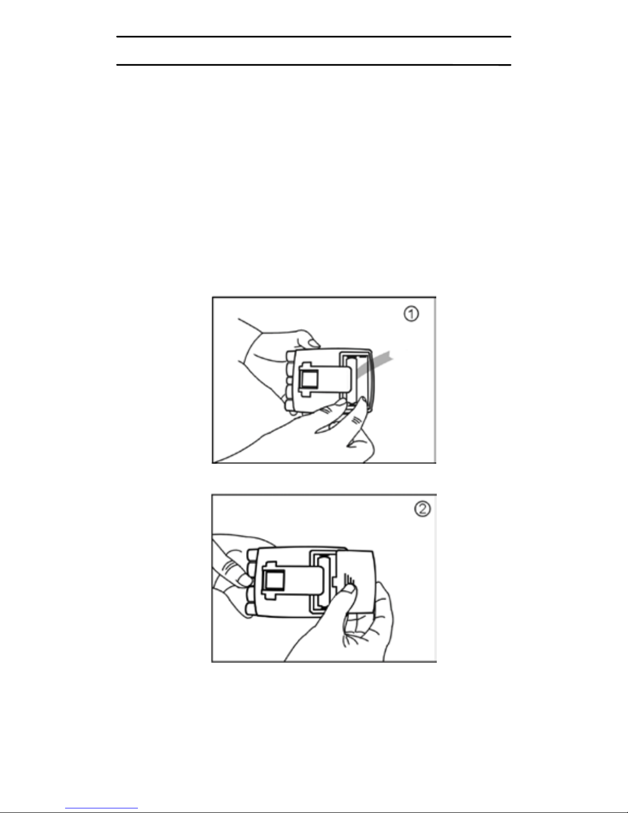
HOW TO ASSEMBLE YOUR UNIT
Assembly of the StimTec TARGET Unit is very sim pl e and
requires only five steps.
STEP 1 BATTERY
Remove the battery cover and insert the battery, as
shown on the diagram inside the battery compartment.
Replace the battery cover.
- 9 -
Page 10
CAUTION
There is a risk of explosion if the batteries are fitted
incorrectly. Do not dis pose of the batteries in a fi re and
keep them out of reach of c hildren. T he batteries must
be removed fro m the unit i f unit is n ot used for a l ong
period of time.
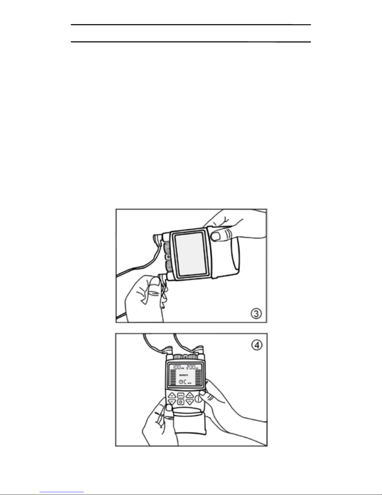
STEP 2 LEADS
If only using one lead, insert into one jack. If using two
leads, insert into both jacks.
Chan nel 1 Channel 2
- 10 -
Page 11
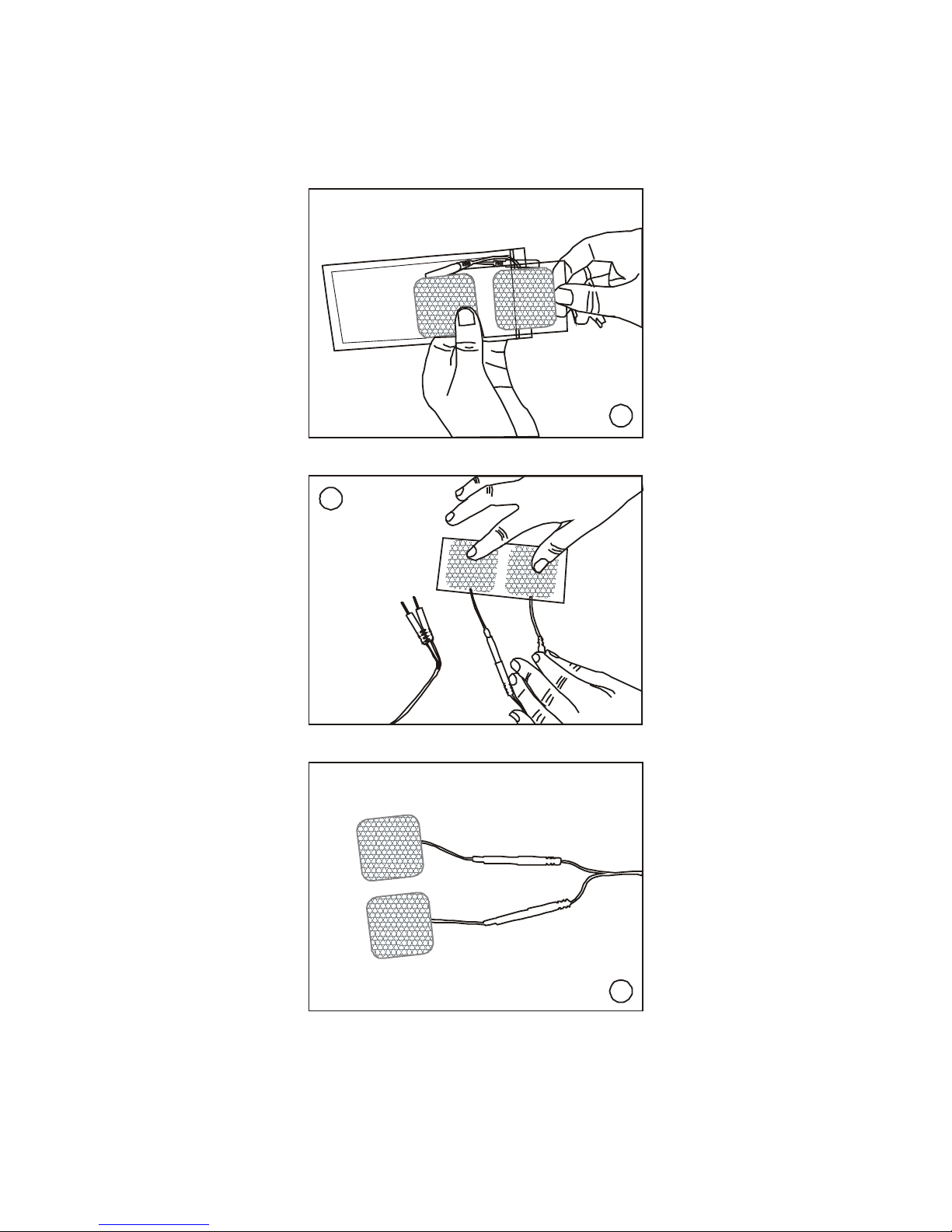
STEP 3 ELECTRODES
Remove electrodes from the bag and connect to the
leads.
5
6
7
- 11 -
Page 12
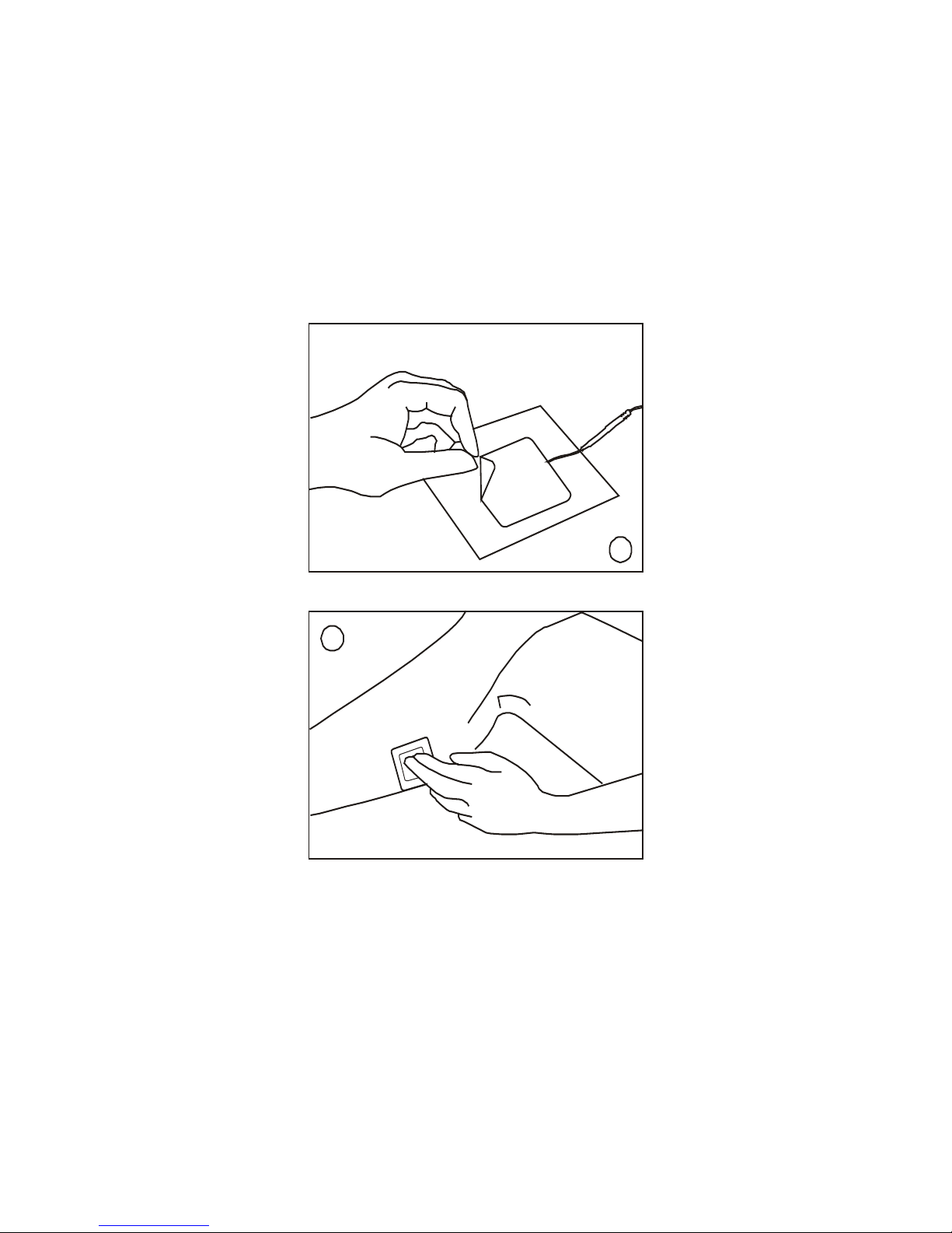
STEP 4 PLACEMENTS OF ELECTRODES
Ensure wherever you intend to place the electrodes, the
skin is cle an and thoroughly dry. Remove the electrodes
from the clear pl astic shiel d and positi on on your body as
required.
8
9
STEP 5 READING
Read “Operation of the StimTec TARGET Unit” on page
14, and decide how to use the unit for the treatment.
- 12 -
Page 13
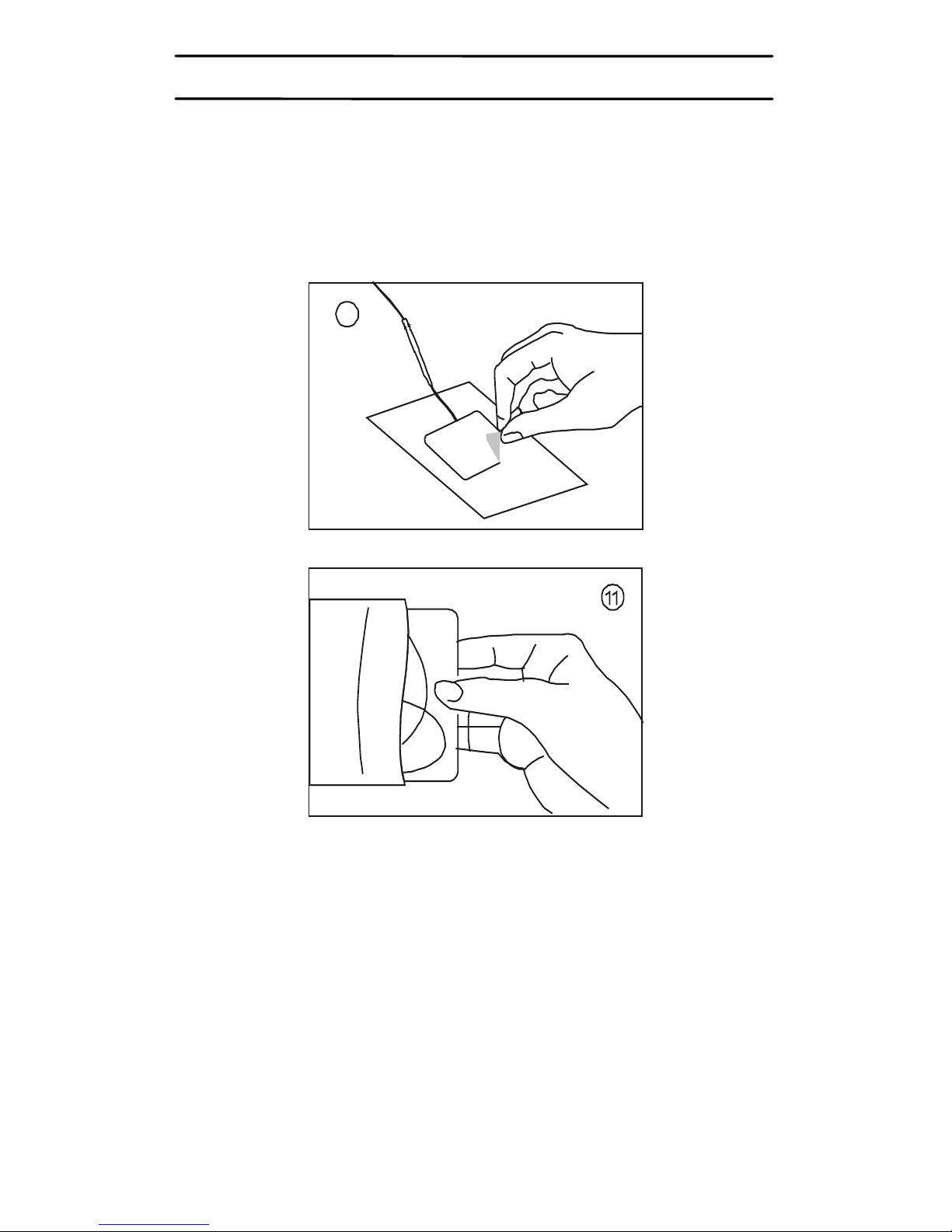
NOTE: AFTER USE
Always ensure that the unit is switched OFF before
removing the electrodes. After use, return the electrodes
to the clear pl astic shields. T here is no need to sep arate
the lead wires from the electrodes.
10
Life of the electrodes: When the electrodes initially lose
their adhesive quality, it is possible to reactivate their
adhesiveness by applying a fin e spray of water. Replace
the electrodes when they lose their adhesive quality in
order not to affect the efficiency of the unit.
- 13 -
Page 14
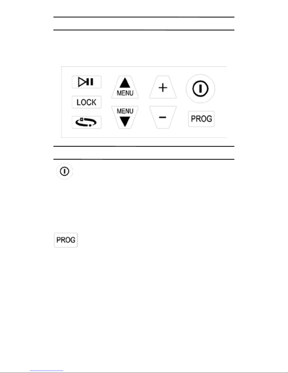
OPERATION OF THE STIMTEC TARGET UNIT
StimTec Target Unit is easy to operate using the keys
shown in the f ol low ing di ag ram.
WHAT DOES EACH KEY DO
This key switches the unit on or off. Press once
and the u nit is o n, the LCD displ ay loc ated at t he front of
the unit will light up, there will be no feeling from either
lead at this point as the intensity always starts at zero.
Press this key again and the unit will switch off.
There are two stimulatio n ty p es availa bl e wi th t he
StimTec TARGET (TENS & EMS).
Press and hold the “Prog” key at least 3 seconds, to
switch between TENS – EMS. The symbol “TENS”, and
“EMS” will display on the LCD accordingly.
Once the stimulation type is selected, press the “Prog”
key to select the related programs.
- 14 -
Page 15

There are a total of 33 programs available:
For TENS treatment:
Program 0-11 --- TENS Preset programs
Program 12-19 --- TENS Manual programs
For EMS treatment:
Program 20-29 --- EMS Preset programs
Program 30-33 --- EMS Manual programs
In EMS preset modes (Prog 20- Prog 29) the treatment
status symbols below will be displayed.
Pressing these two keys to go through and
select the following parameters one by one (manually
selectable only):
TENS Manual Mode(P12-P19) :
FREQUENCY (Hz)
PULSE WIDTH (μs)
Waveform
Treatment Timer (min)
EMS Manual Mode(P30-P33) :
FREQUENCY (Hz)
PULSE WIDTH (μs)
Waveform
Treatment Timer (min)
SYNCHRONOUS/ALTERNATING
ON TIME (sec)
OFF TIME (s ec )
RAMP UP TIME (sec)
RAMP DOWN TIME (sec)
- 15 -
Page 16
When one of the above parameters has been selected,
the correspo nding digits or l etters or sy mbols on the LCD
are flashin g, then you can use “+” or “–” key to adjust that
parameter value. Press a “MENU” key to save the value
and skip to t he next parameter s etting . If there is no in put
detected w ithi n 5 sec o nds, t he unit will autom ati cal ly save
the value you last set as the treatment parameter.
When MENU (▲/ ▼) key is pressed, the output level
goes immediately to zero.
By pressing “+” or “–” keys you can increase
or decrease the value of the parameter which has been
selected by the “MENU” keys and is now flashing. An
auto-repeat function is available; when +/- key is held
down over 1 second, the value of the parameter will
increase/dec rease 1 step per 1/ 4 second until the key is
released.
Pressing this key will pause the current
treatment. When the unit is paused, the intensity level
goes down to zero, and “►II” is displayed on the LCD. To
continue, press the key again. The treatment will
continue at the s am e intensity and prog ress prior to being
paused.
Press and h ol d thi s key for at l east 3 seco nds to
LOCK or UNLOCK par ameters. When the unit is locked,
only intensity and treatment timer can be adjusted.
The symbol displayed on the LCD screen indicates
that the unit is locked.
- 16 -
Page 17
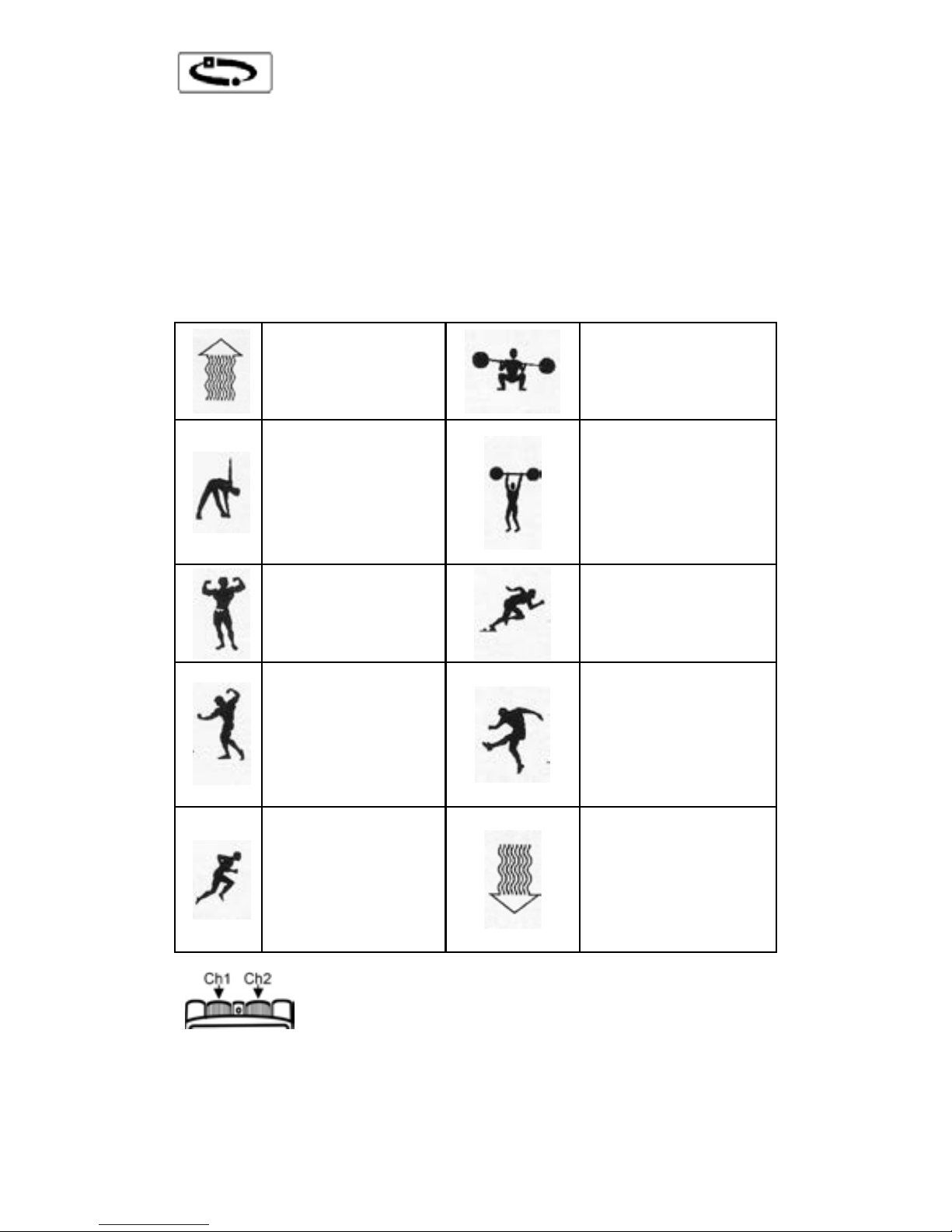
For TENS pres et m od es (Prog 0- P ro g 11), if a
preset mode is working, press this key to skip a phase
(sub-programs Ⓐ Ⓑ Ⓒ ). For EMS preset modes
(Prog 20- Prog 29), if a preset mode is working, press this
key to choose the treatment status.
The treatment status symbols below will be displayed
automatically base on the choice of the user:
WARM-UP
FORCE 1
AEROBIC
EXERCISE
FORCE 2
TONING
FAST FORCE
HARDENING
EXPLOSIVE
FORCE
RESISTING
FORCE
PROGRESSIVE
RECUPERATION
These two rotated knobs located on the top
of the uni t adjust the inte nsity of ch annels, th e left si de is
for Ch1, an d the rig ht side is for Ch2. Turn the knob a nd
the intensity over zero, the corresponding LED light
located at the top of the knob will light up.
- 17 -
Page 18

SPECIFICATION
Model: StimTec Target
Channel: Dual
TENS:
Intensity 0-150mA zero to peak at 500ohm load
Frequency 1-150 Hz
Pulse width 50, 60, 70, 80, 90, 100, 110, 120, 130,
140, 150, 160, 170, 180,190, 200, 210,
220, 230, 240, 250μs
Waveform Symmetrical bi-phase rectangular,
Asymmetrical bi-phase rectangular,
Mono-phase positive rectangular,
Mono-phase negative rectangular,
Alternated bi-phasic rectangular
Treatment timer Continuous, 15, 30, 45, 60, 90min
The PRESET program applies a sequence of 3
sub-programs Ⓐ Ⓑ Ⓒ, optim ized to treat the specific
pain situation. The characters Ⓐ, Ⓑ or Ⓒ will flash,
showing the phase in use or will be ON to show the
completed phase.
Mode Constant A – Both Pulse Rate and Pulse Width
are adjustable. Default values are PR=3Hz and
PW=250μs characterized by a de-contraction effect . Use
this program if you want to relax the painful area. The
stimulation level must be set to produce a gentle
muscular contraction.
Mode Constant B – Both Pulse Rate and Pulse Width
are adjustable. Default values are PR=10Hz and
PW=150μs characterized by an endorphins stimulating
- 18 -
Page 19

effect. Use this program if you want pr oduce endorphins
at the painful area. The stimulation may reach the
muscular contraction level. If the Pulse Rate will be
increased, the stimulation level must be set to avoid the
muscular contraction.
Mode Constant C – Both Pulse Rate and Pulse Width
are adjustable. Default values are PR=70Hz and
PW=50μs characterized by an endorphins stimulating
effect through the Gate-control mechanism. Use this
program in case of ACUTE PAIN. The stimulation level
must be set to avoid the muscular contraction.
Mode MODulation SW (A) – Pulse Rate Sweep
modulation. Pul se Rate is aut omatically modulated withi n
F1=50Hz and F2= 80Hz (adj ustabl e); e ach fre quency st ep
will last 1 sec. F2 can be changed only if the intensity
level of both channels are set to 0. The Pulse Width is
200μs (adjustable from 50μS to 250μS).
Mode MODulation 2F (B) – Pulse Rate Dual
Frequencies modulation. Pulse Rate is automatically
changed every 5 seconds, between F1=70Hz (adjustable)
and F2=5Hz. F 1 can be changed onl y i f the intens ity lev el
of both channels are set to 0. The Pulse Width is 50μs
(adjustable from 50μS to 250μS).
Mode Bur st A – 3 second Burst s equence = 1s on, 2s off.
Both Pulse Ra te and Puls e Width are adjusta ble. Default
values are PR=30Hz and PW=250μs. The stimulation
level must be set to produce a gentle muscular
contraction.
Mode Burst B – 1.5 second Burst sequence = 0.5s on,
1s off. Both Pulse Rate and Pulse Width are adjustable.
Default values are PR=50Hz and PW=200μs. The
- 19 -
Page 20

stimulation level must be set to produce a gentle
muscular contraction.
Mode Burst C – 0.75 second Burst sequence = 0.25s on,
0.5s off. Both P ul se R ate an d P ul se W idth are adjustable.
Default values are PR=100Hz and PW=150μs. The
stimulation level must be set to produce a gentle
muscular contraction.
EMS:
Intensity 0-130mA to peak at 500ohm load
Frequency 1-110 Hz
Pulse width Positive phase: 50-400μs, in steps of
50μs
Waveform Symmetrical Bi-Phasic rectangular,
Alternated Bi-Ph asic re ctangul ar
Ramp up time 0-5s in steps of 1s
Ramp down time 0-5s in steps of 1s
On time 1-60s in steps of 1s
Off time 0-60s in steps of 1s
Treatment timer Continuous, 10, 20, 30, 45, 60, 90min
Program 30-33 (manual) – When using ALTERNATING
Frequency, ensure that the “Ramp up Time”, “On Time”,
and “Ramp down Time” equals “Off Time”.
Ramp Up + On Time + Ramp Down = Off Time
The will appear on your screen if this formula is not
followed in EMS manual mode.
- 20 -
Page 21

OTHER FEATURES
1. When the unit is tur ned on, if an y of the keys are not
pressed within 5 minutes, it will automatically shut off.
2. When the treatment timer has been set, it begins to
count down one minute by one minute and is
displayed on th e LCD. Once it counts down to zero,
the device automatically shuts off.
3. The treatment time will be accumulatively recorded
when the output level is above zero, by pressing
key and “MENU ▼” key for 4 seconds the
treatment time accumulated in minute can be
displayed. Repeat to return back to the previous
normal dis play i n toggl e. By pressi ng key and
“-” key for 4 seco nds will clear the tre atment time to
zero.
4. When the program changes, the output level will go
down to zero immediately.
5. When the unit i s turned on, it will auto matically ente r
the mode that t he unit had work ed in before the unit
was turned off.
6. When the battery is low, the battery icon will flash
indicating that the batteries should be replaced.
7. When one or both of the electrodes are not placed
firmly on the skin, the output level goes immediately
to zero.
- 21 -
Page 22
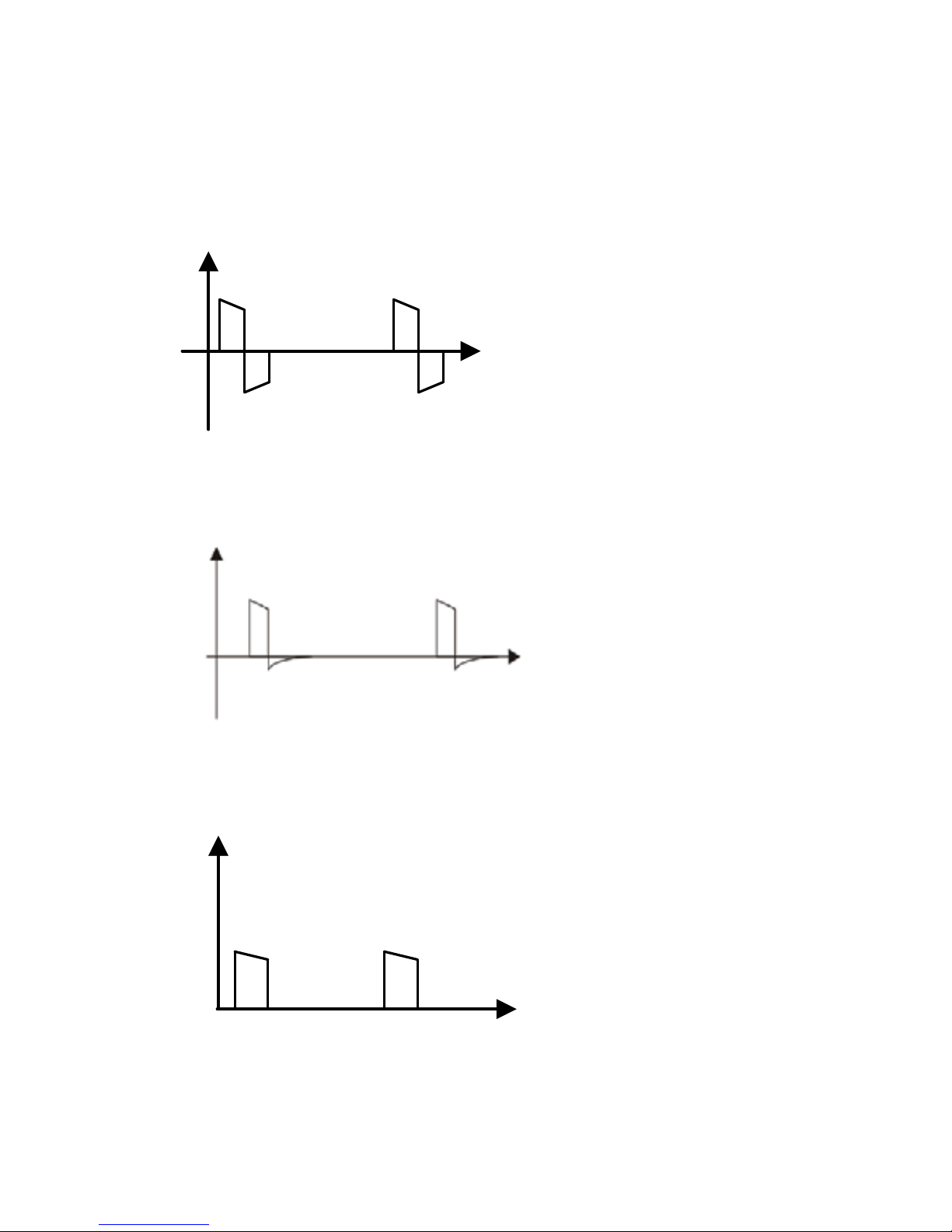
Waveform Information
There are 5 types of wav eform s:
(1). Symmetrical Bi-Phasic rectangular waveform
Amplitude
Time
(2). Asymmetrical Bi-Phasic rectangular waveform
Amplitude
Time
(3). Mono-Phasic positive waveform
Amplitude
Time
- 22 -
Page 23
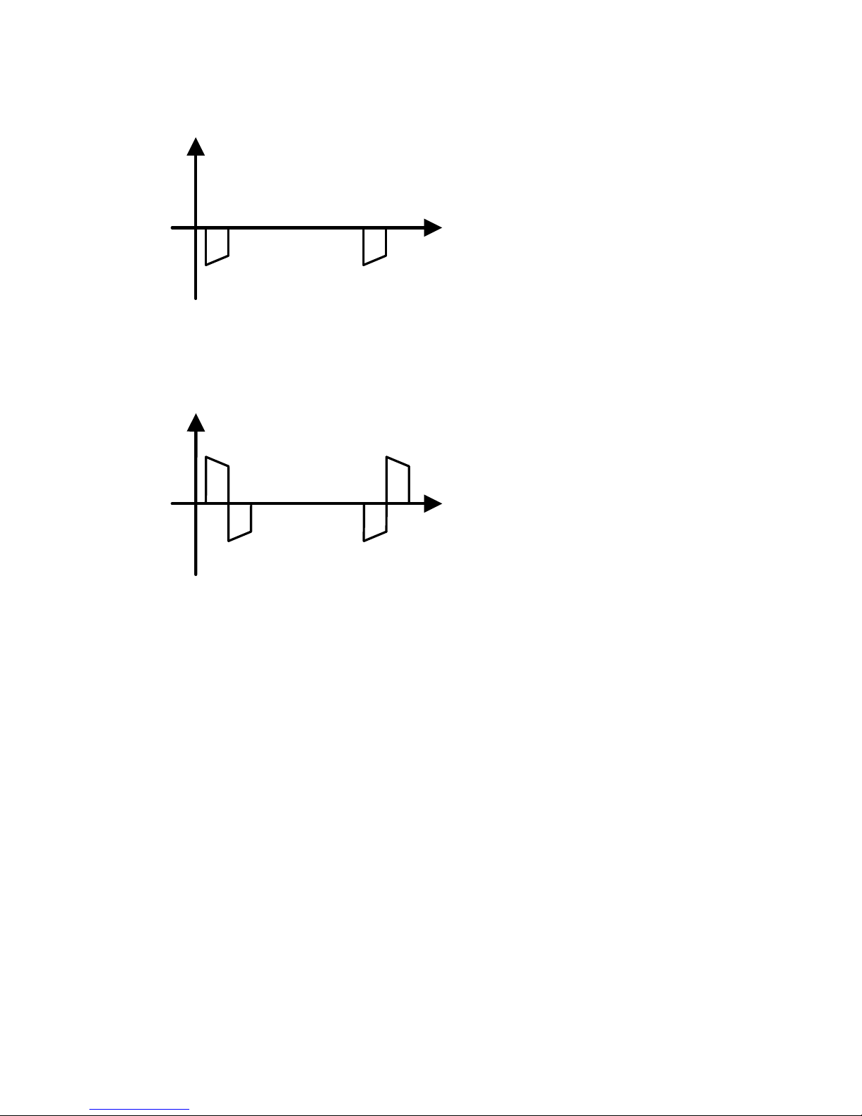
(4). Mono-Phasic negative waveform
Amplitude
Time
(5). Alternated Bi-Phasic rectangular waveform
Amplitude
Time
- 23 -
Page 24
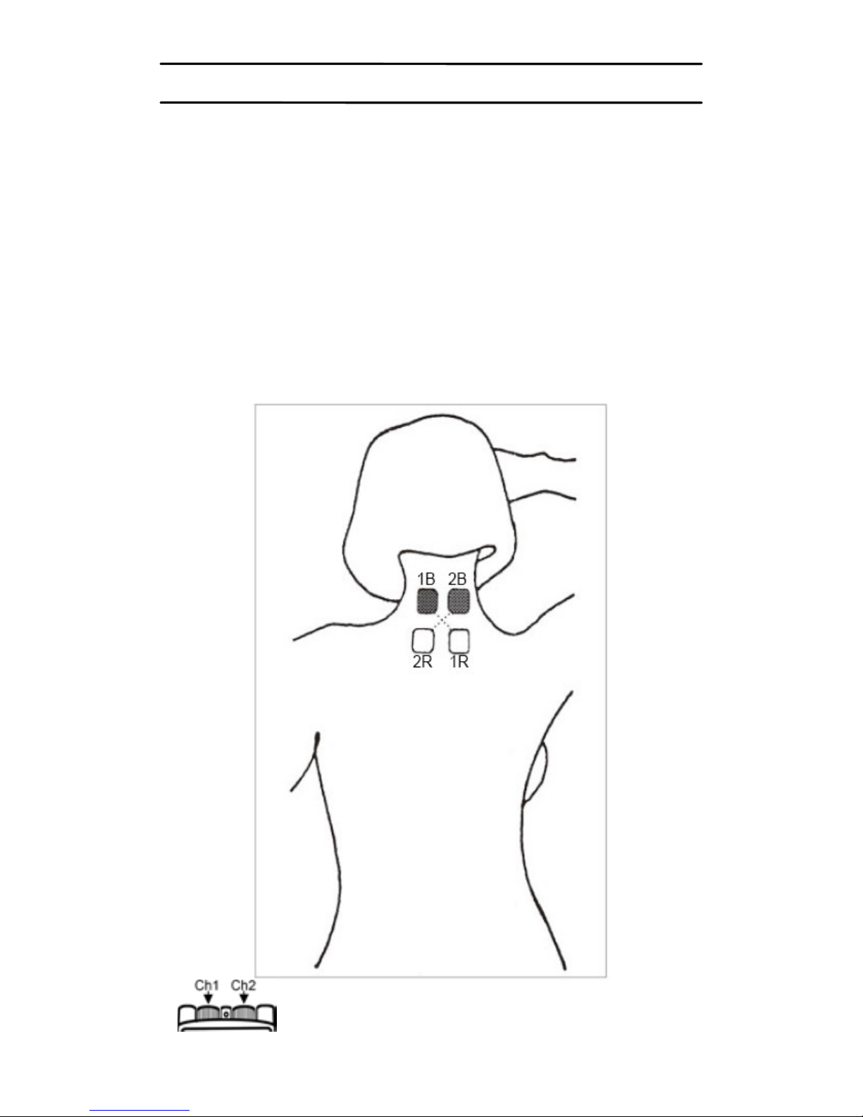
ELECTRODES PLACEMENT
Please study the body maps in this guide, which illustrate
placement of the electrodes depending on your symptoms.
Examples of electrodes placement for TENS:
0 – NECK PAIN
Using both leads, place the electrodes at the back of the
neck and over the top of your shoulders.
Note: Do not place electrodes on the side or front of the
neck.
1B =Channel 1 black / 1R =Channel 1 red
2B =Channel 2 black / 2R =Channel 2 red
- 24 -
Page 25
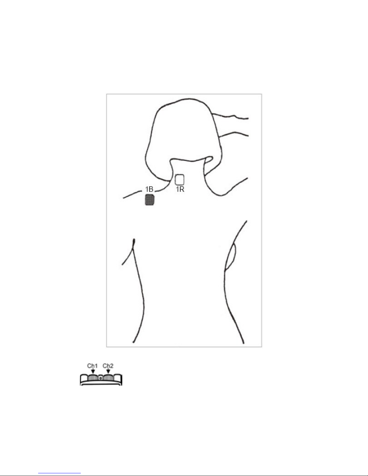
1 – TORTICOLLIS
Using a sin gle chan nel, place the el ectrode s, over the area
of maximum pain.
1B =Channel 1 black / 1R =Channel 1 red
2B =Channel 2 black / 2R =Channel 2 red
- 25 -
Page 26
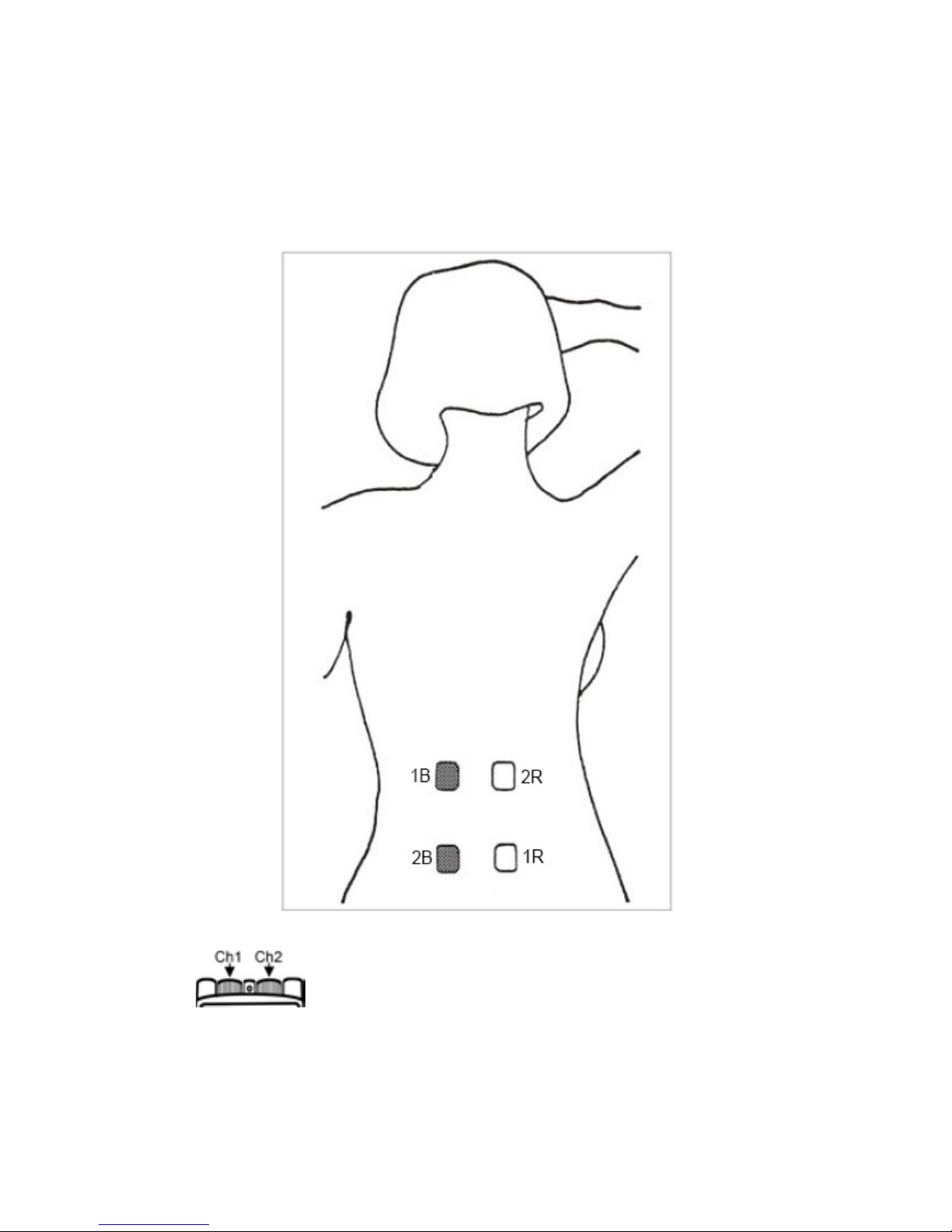
2 – LOW BACK PAIN
Using both leads, place electrodes on either side of the
spine, crossing the channels, at the site of pain.
1B =Channel 1 black / 1R =Channel 1 red
2B =Channel 2 black / 2R =Channel 2 red
- 26 -
Page 27
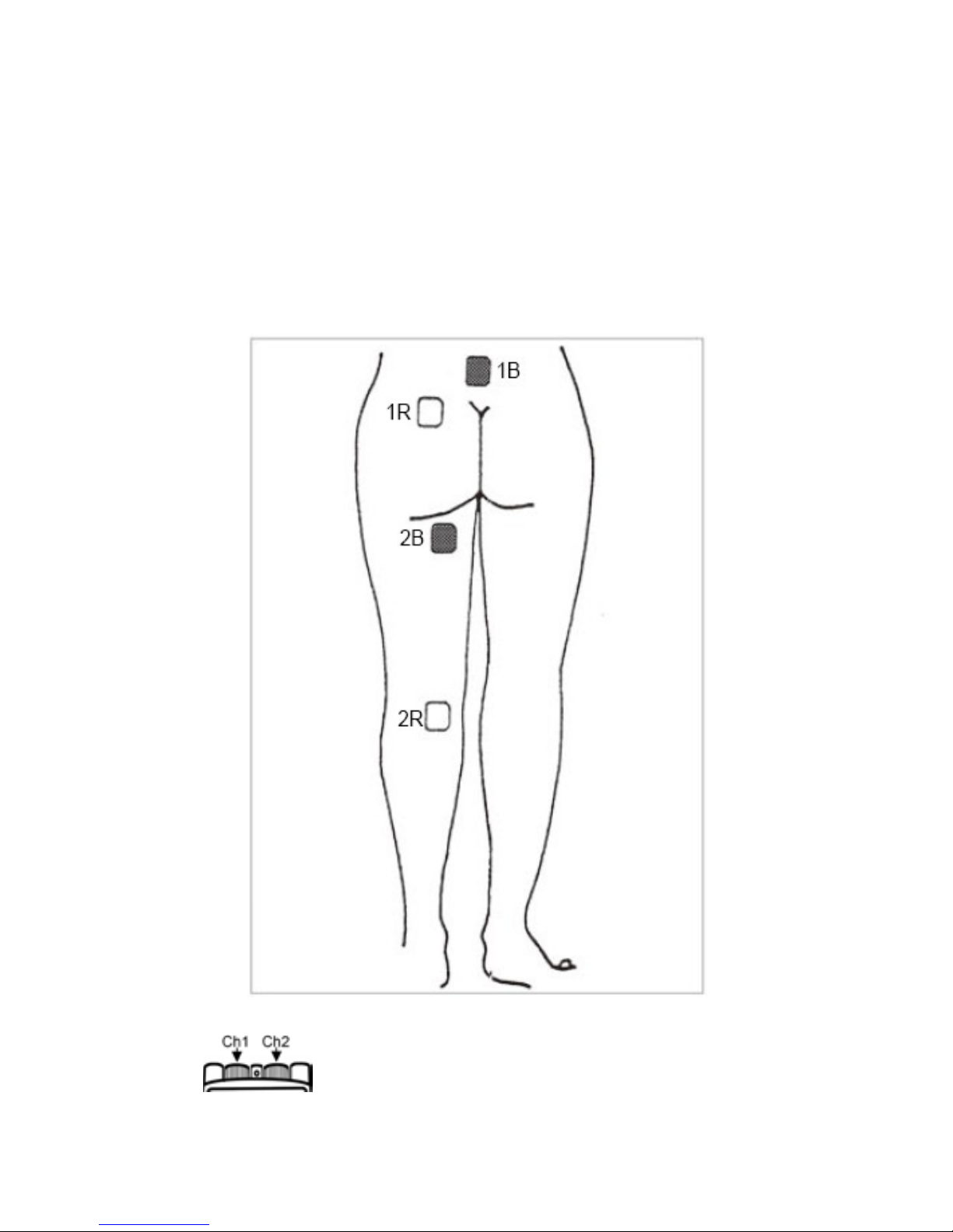
3 – SCIATICA
Using both leads, take the first lead and place the electrode
with the black adapter on your lower back on one side of
your spi ne, and the second electrode with the red adapter
at the top of the back of your leg. With the second lead,
place the other two electrodes lower down as illustrated.
1B =Channel 1 black / 1R =Channel 1 red
2B =Channel 2 black / 2R =Channel 2 red
- 27 -
Page 28
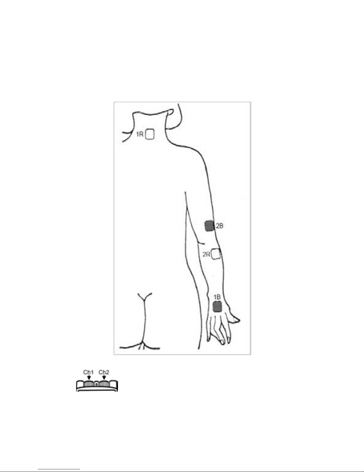
4 – EPICONDYLITIS
Using both leads, place electrodes on either side of the
elbow.
1B =Channel 1 black / 1R =Channel 1 red
2B =Channel 2 black / 2R =Channel 2 red
- 28 -
Page 29
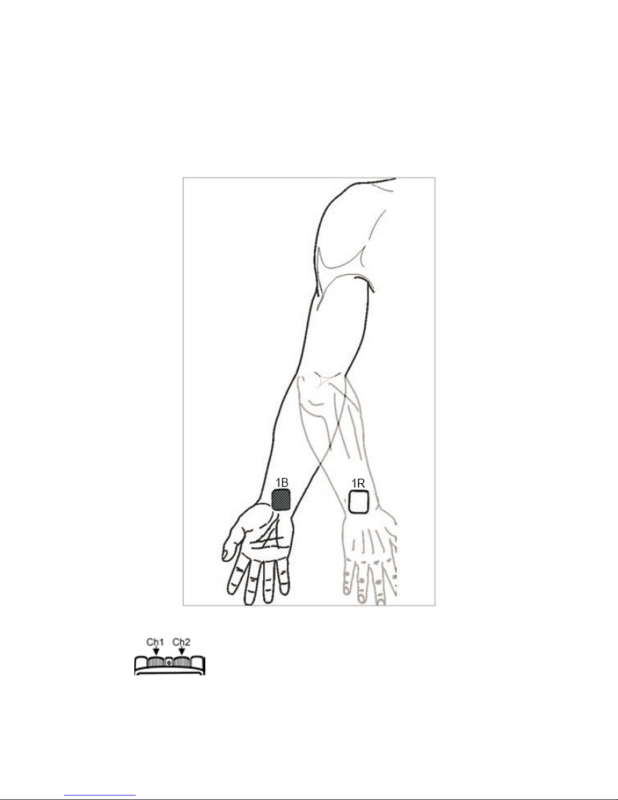
5 – WRIST PAIN
Using a single channel, place the electr odes over th e area
of maximum pain on each side of the wrist.
1B =Channel 1 black / 1R =Channel 1 red
2B =Channel 2 black / 2R =Channel 2 red
- 29 -
Page 30
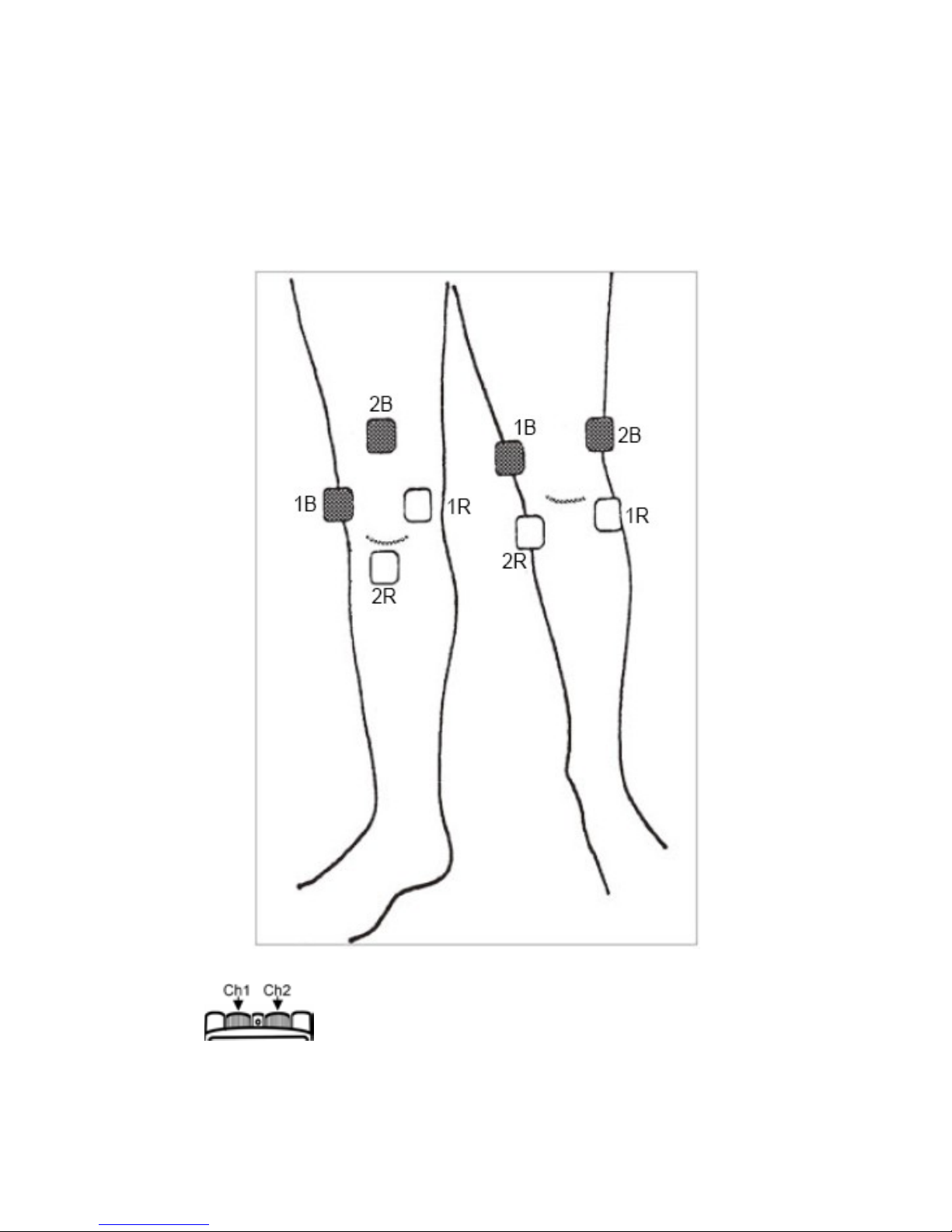
6 – KNEE PAIN (CHRONIC)
Using both leads, place electrodes over the top and base of
the k nee. Avoid placing directly on the kneecap.
Below are two common application techniques.
1B =Channel 1 black / 1R =Channel 1 red
2B =Channel 2 black / 2R =Channel 2 red
- 30 -
Page 31
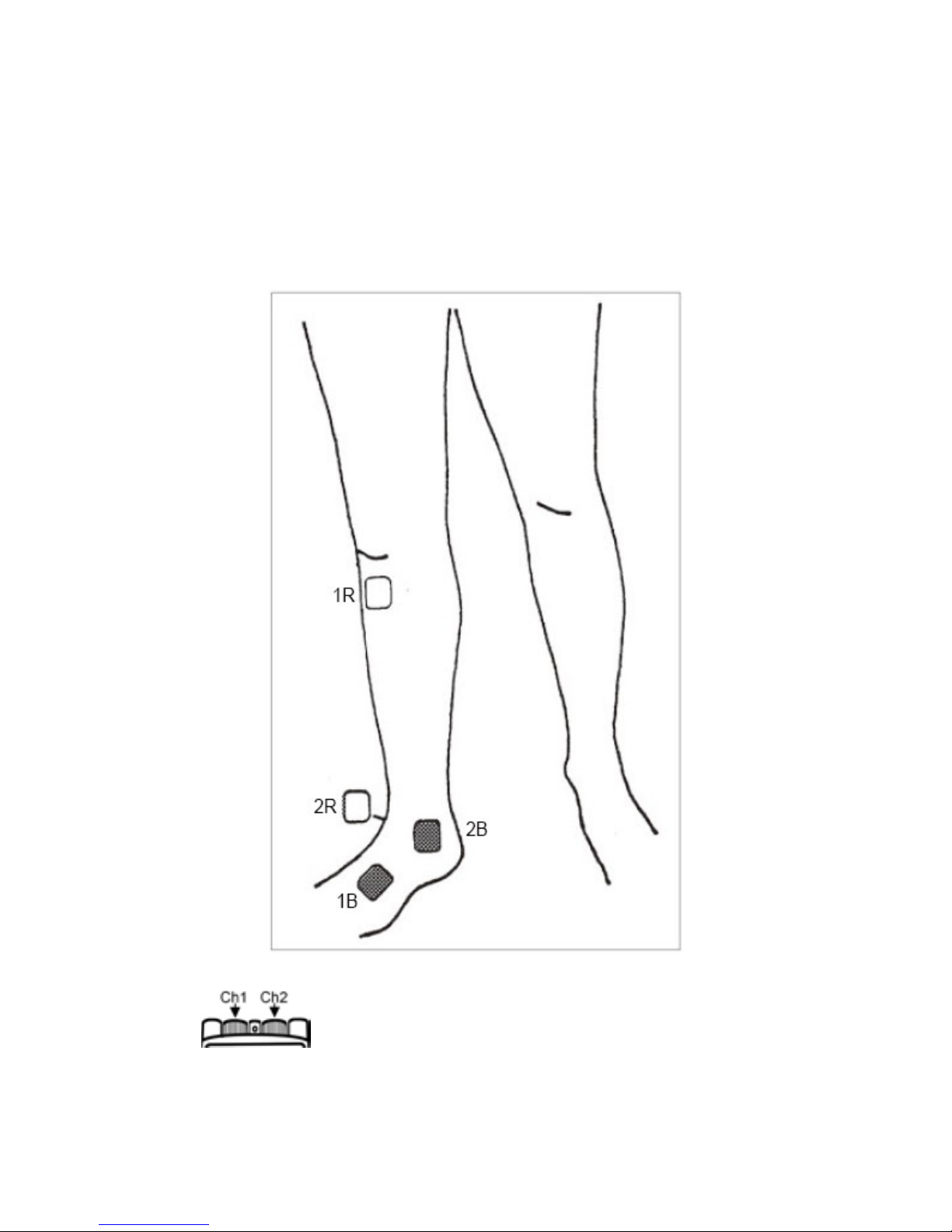
7 – ANKLE SPRAIN
Using both leads, place an electrode from one lead on
either side of the leg, and the other electrode on your ankl e.
The el ectro des f rom the othe r l ead will be pl ace d al ong the
affected nerve.
1B =Channel 1 black / 1R =Channel 1 red
2B =Channel 2 black / 2R =Channel 2 red
- 31 -
Page 32
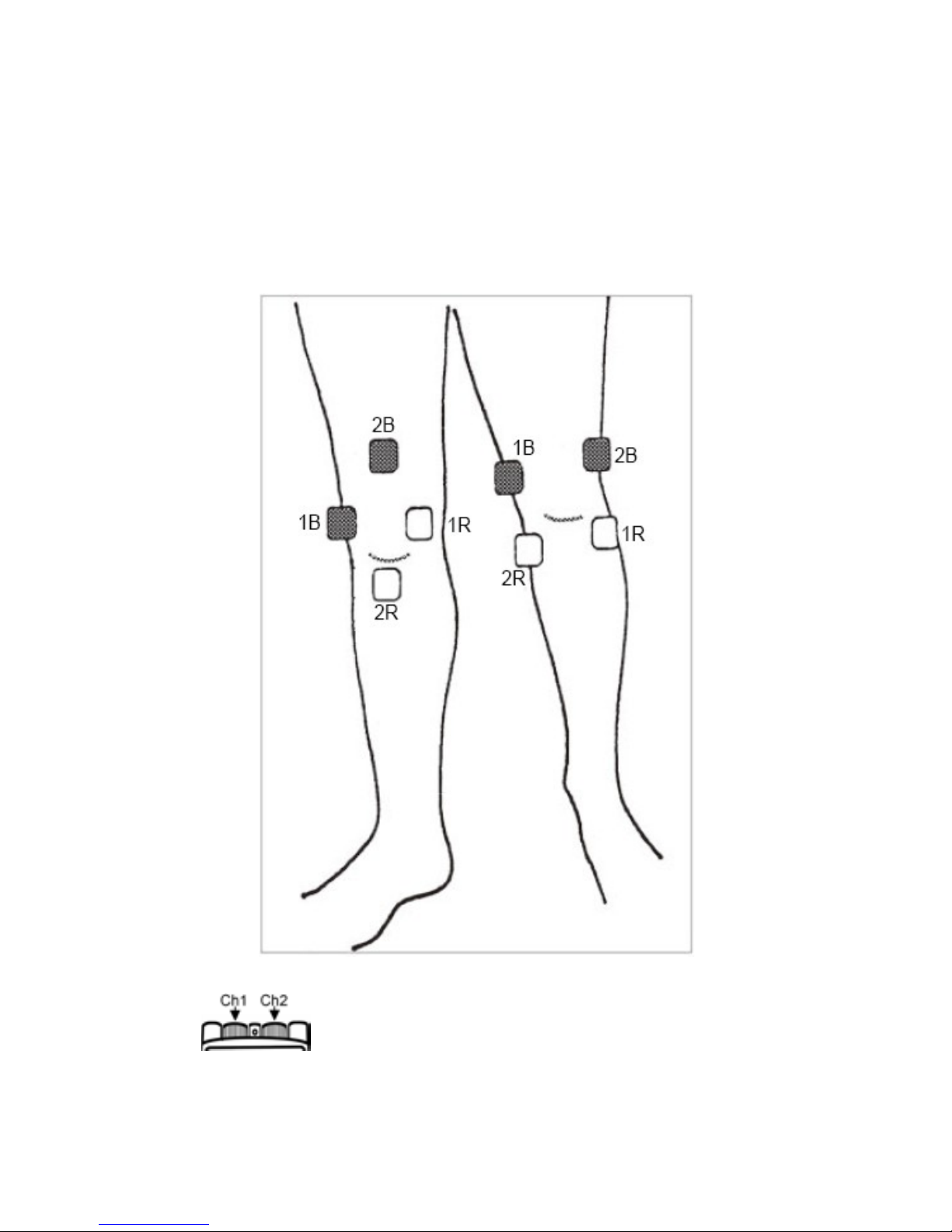
8 – KNEE PAIN (ACUTE)
Using both leads, pl ac e electrodes over the top and base of
the k nee. Avoid placing directly on the kneecap.
Below are two common application techniques.
1B =Channel 1 black / 1R =Channel 1 red
2B =Channel 2 black / 2R =Channel 2 red
- 32 -
Page 33
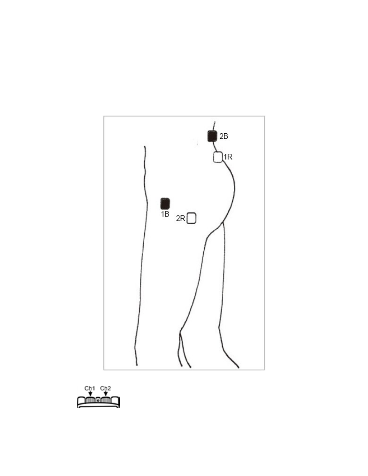
9 – HIP PAIN (COXALGIA)
Using both lead wires, pl ace one el ectrode f rom each le ad
wire o n your lower back on t he si de of the spine relate d to
the affected hip. The rem aining el ectrod es must be plac ed
on the area of pain, on your hip.
1B =Channel 1 black / 1R =Channel 1 red
2B =Channel 2 black / 2R =Channel 2 red
- 33 -
Page 34
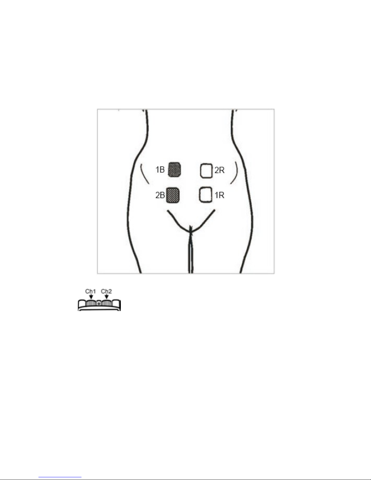
10 – MENSTRUAL PAIN
Using both lead wires, place electrodes over the tummy
area as shown.
1B =Channel 1 black / 1R =Channel 1 red
2B =Channel 2 black / 2R =Channel 2 red
- 34 -
Page 35
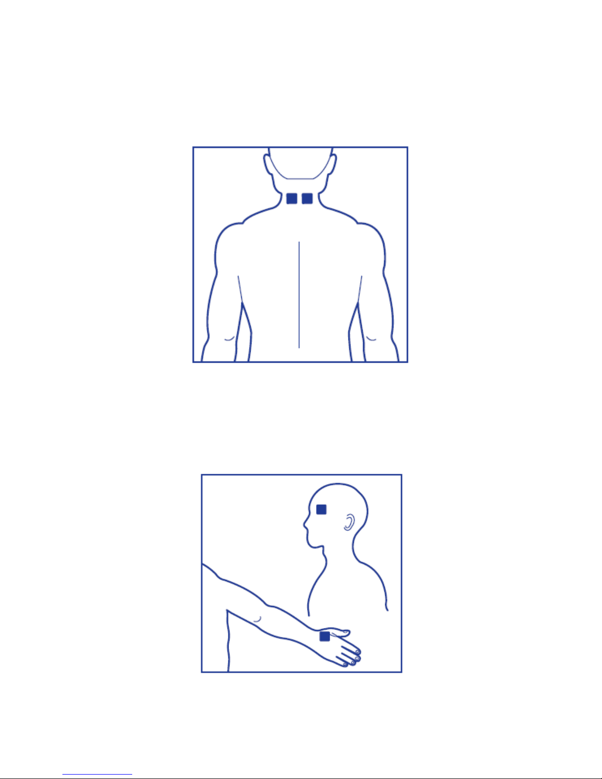
11 – MIGRAINE
Using only 2 electrodes, place each on the back of the
neck.
Note: Do not place electrodes on the side or front of the
neck.
MIGRAINE (ADDITIONAL POSITION)
Using onl y 2 electrod es, place one on the lef t temple, an d
the other on the back of your right hand between your
thumb and first finger.
Note: If only 2 electrodes are being used, connect both
electrodes to the 2-lead single-channel lead wire.
1B 1R
1R
1B
- 35 -
Page 36
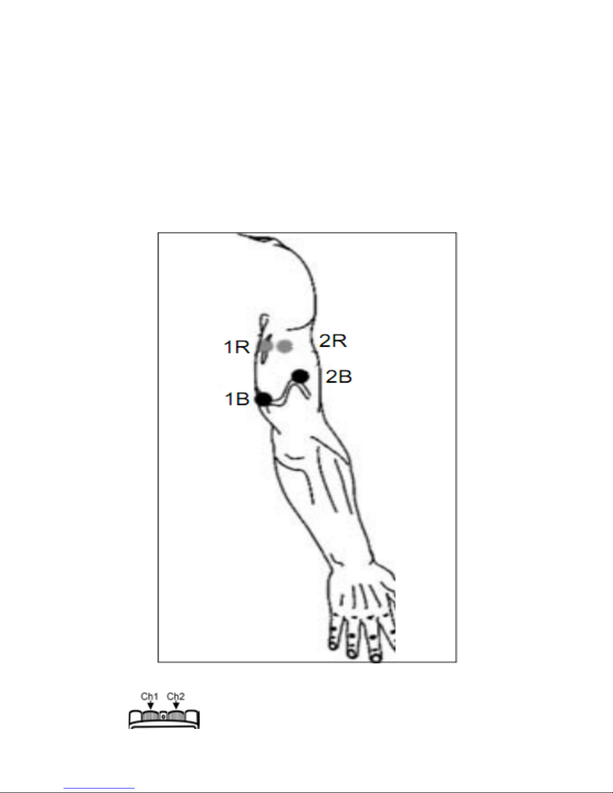
Examples of electrodes placement for EMS:
Please Note: Simply select your program mode, and then
place electrodes on the required treatment area
according to the following diagrams.
20 – TRICEPS
1B =Channel 1 black / 1R =Channel 1 red
2B =Channel 2 black / 2R =Channel 2 red
- 36 -
Page 37
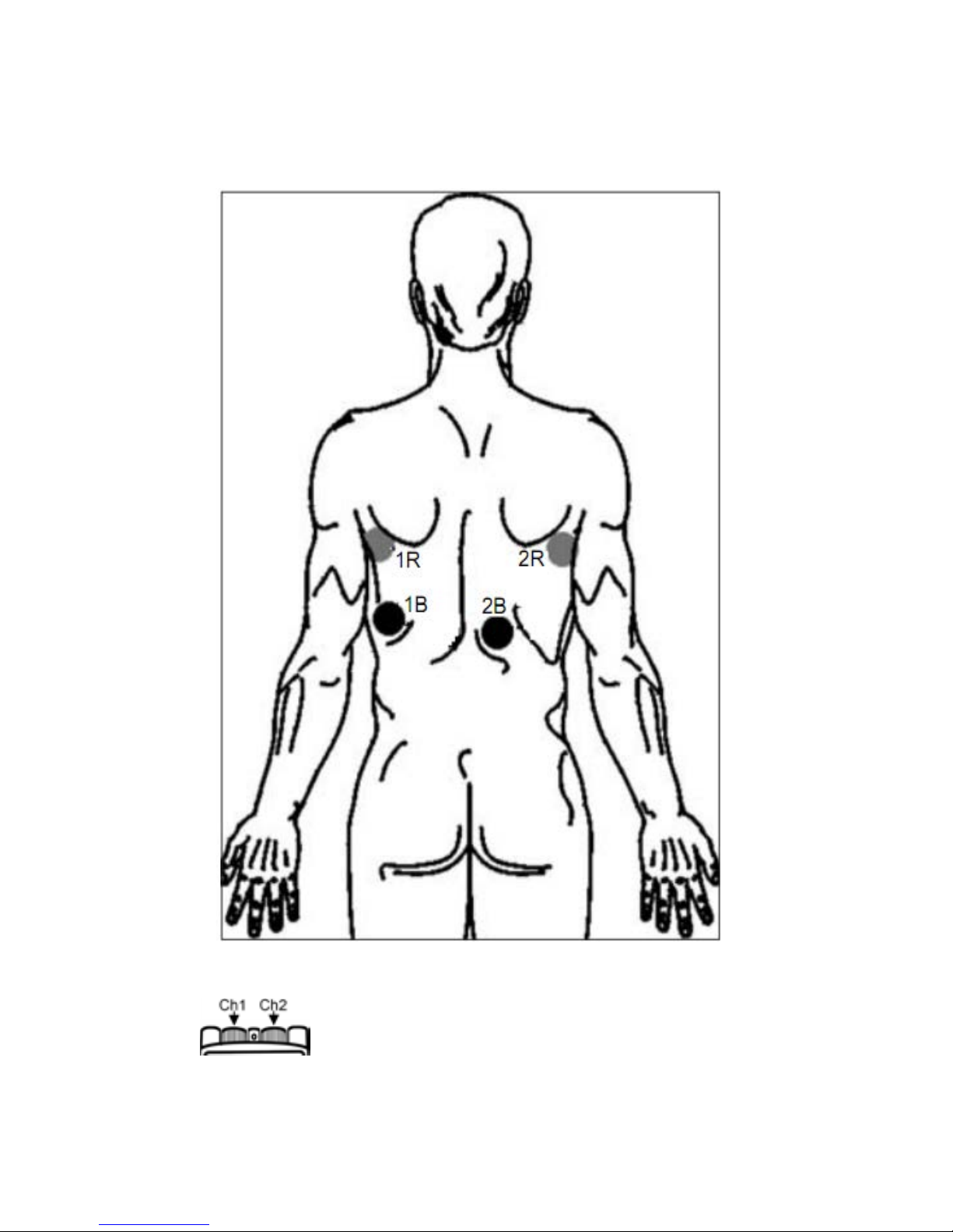
21 – LATISSIMUS DORSI
1B =Channel 1 black / 1R =Channel 1 red
2B =Channel 2 black / 2R =Channel 2 red
- 37 -
Page 38
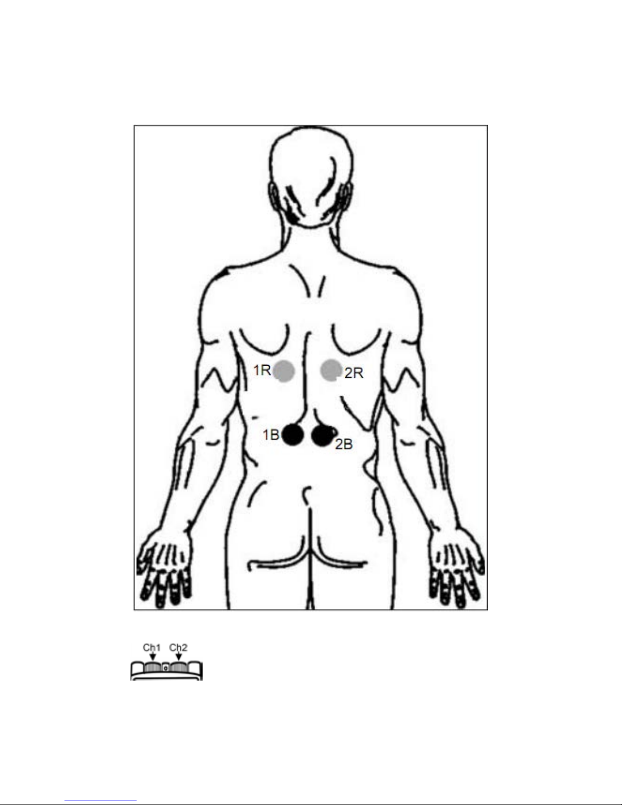
22 – SPINALIS MUSCLE (BACK)
1B =Channel 1 black / 1R =Channel 1 red
2B =Channel 2 black / 2R =Channel 2 red
- 38 -
Page 39
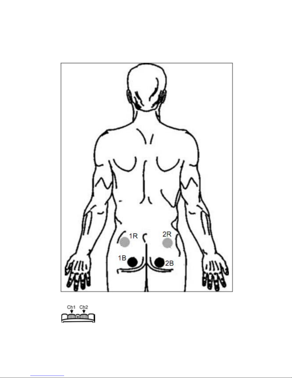
23 – GLUTEUS
1B =Channel 1 black / 1R =Channel 1 red
2B =Channel 2 black / 2R =Channel 2 red
- 39 -
Page 40
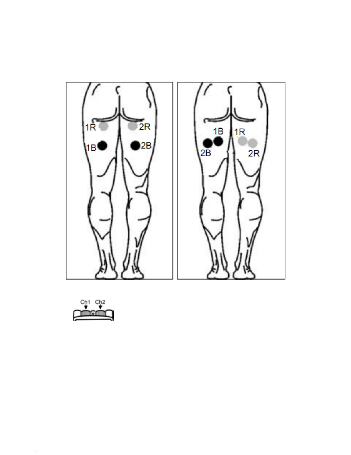
24 – HAMSTRINGS
1B =Channel 1 black / 1R =Channel 1 red
2B =Channel 2 black / 2R =Channel 2 red
- 40 -
Page 41
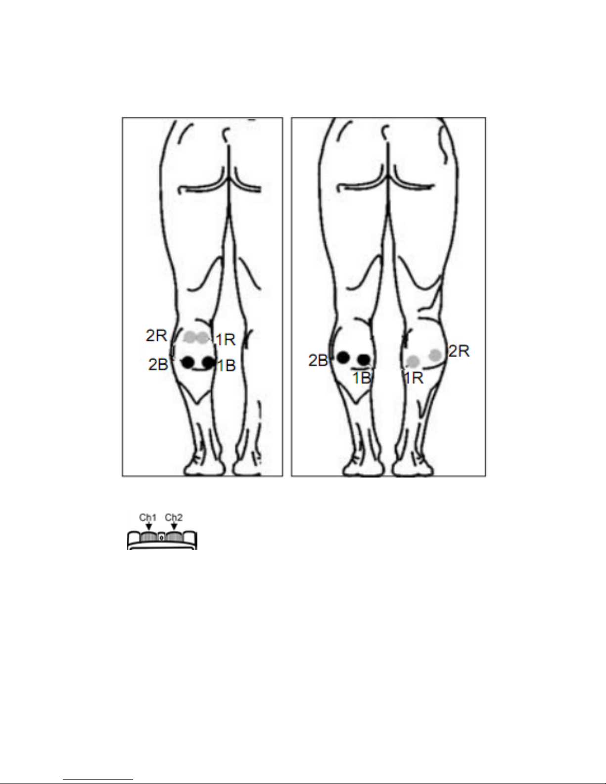
25 – CALVES
1B =Channel 1 black / 1R =Channel 1 red
2B =Channel 2 black / 2R =Channel 2 red
- 41 -
Page 42
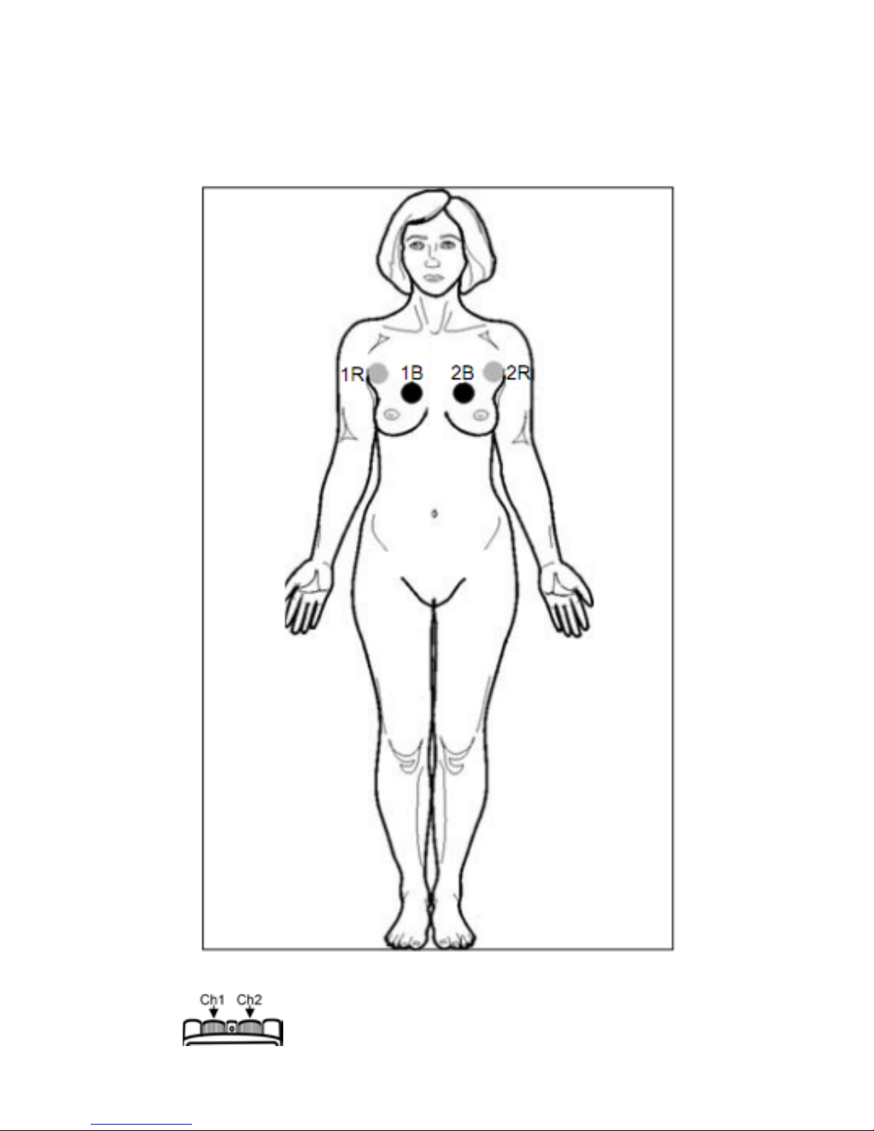
26 – BREAST
1B =Channel 1 black / 1R =Channel 1 red
2B =Channel 2 black / 2R =Channel 2 red
- 42 -
Page 43
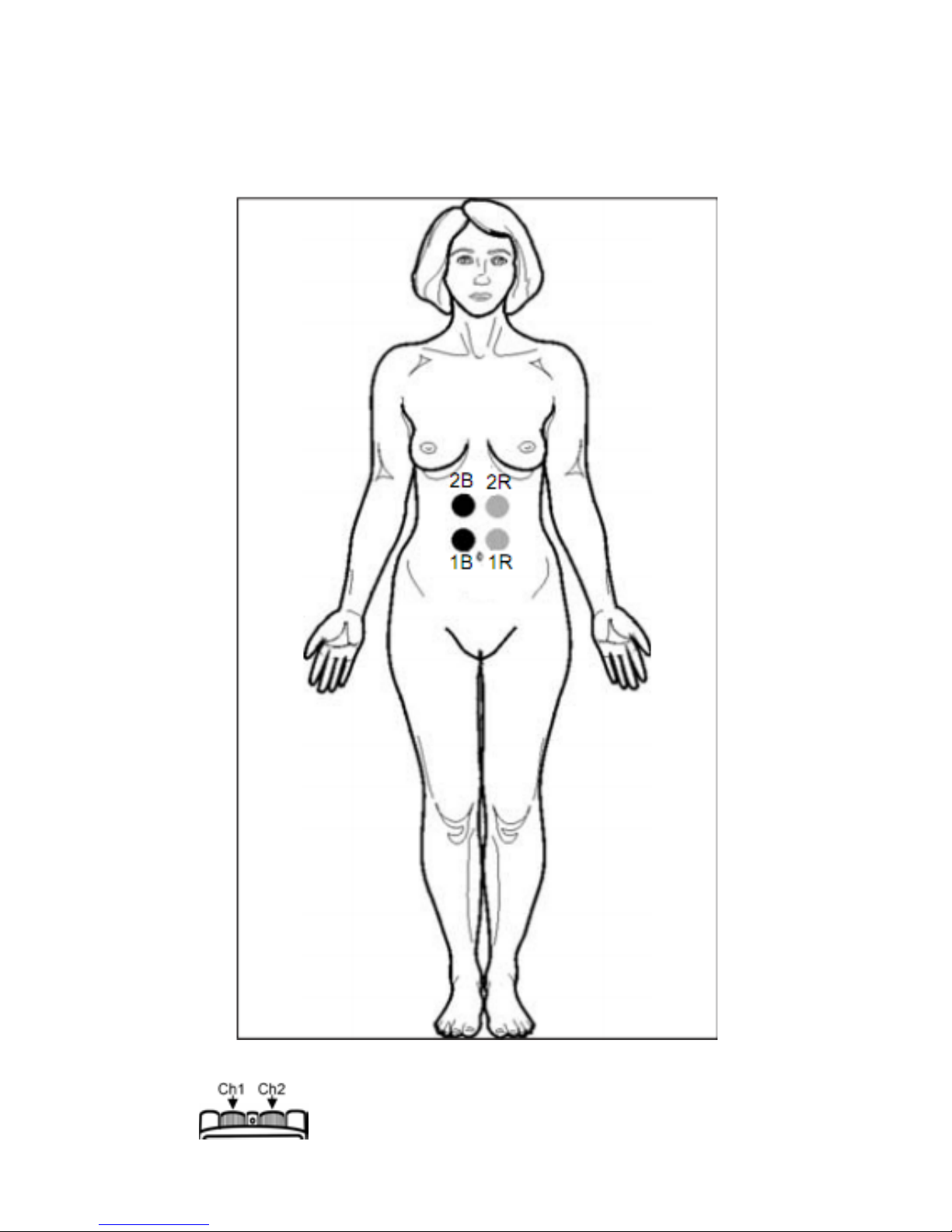
27 – ABDOMEN
1B =Channel 1 black / 1R =Channel 1 red
2B =Channel 2 black / 2R =Channel 2 red
- 43 -
Page 44
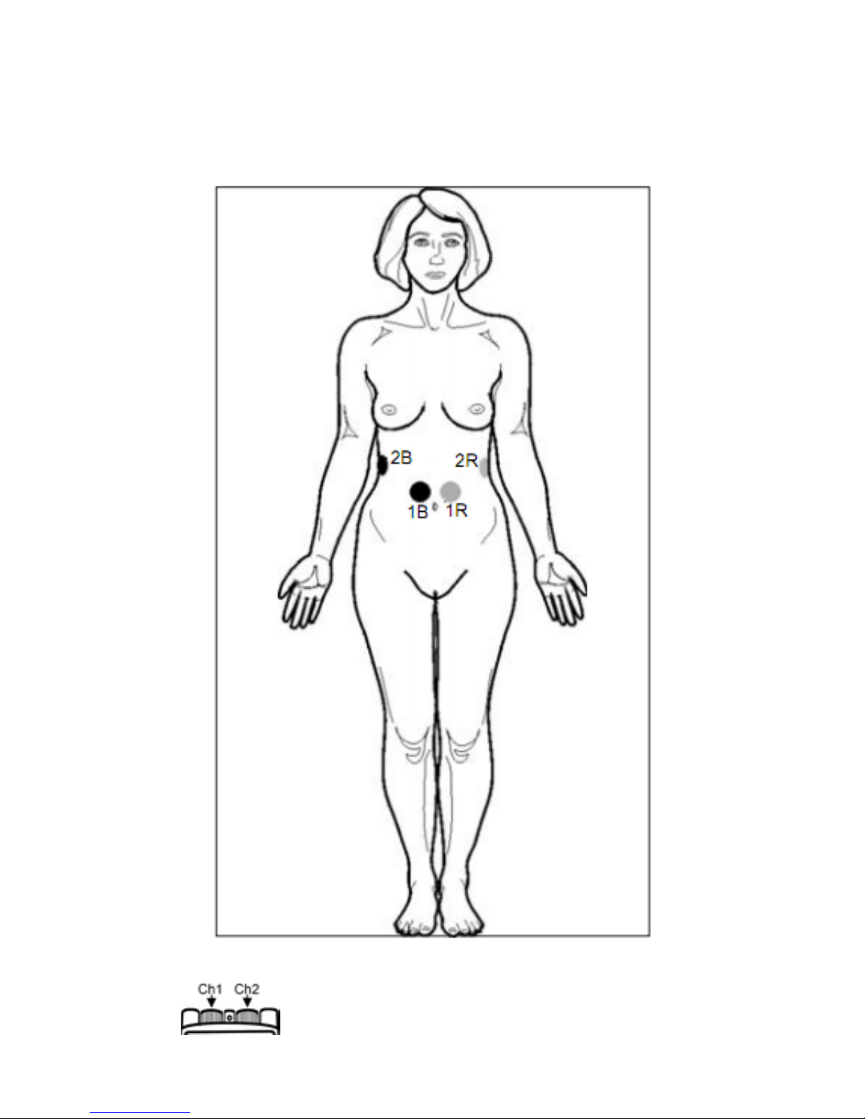
28 – ABDOMEN + W AIST
1B =Channel 1 black / 1R =Channel 1 red
2B =Channel 2 black / 2R =Channel 2 red
- 44 -
Page 45
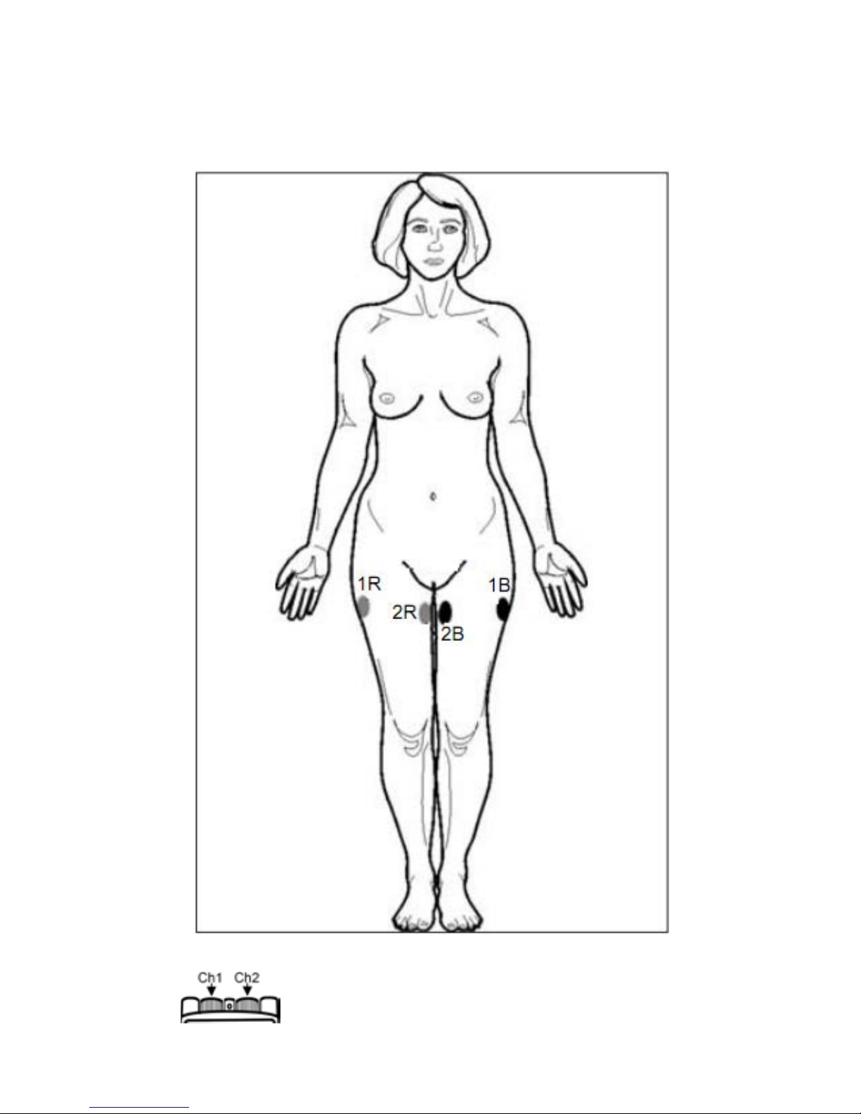
29 – THIGHS
1B =Channel 1 black / 1R =Channel 1 red
2B =Channel 2 black / 2R =Channel 2 red
- 45 -
Page 46

ELECTRODES
The electrodes that are supplied with your STIMTEC
TARGET Unit are self-adhesive and can be used
several times. Skin must be allowed to breathe, s o the
electrodes shoul d be remov ed periodi cally. When not in
use, the electrodes should be placed onto the clear
plastic shield.
The condition of the electrodes has a direct effect on
conductivity, and therefore the effectiveness of the
treatment. When the electrodes start to lose their
adhesive quality, it is possible to reactivate their
adhesiveness by applying a fine spray of water to the
gel side of the electro de. In ti me, this tec hnique will not
work, the gel will not reactivate, and new electrodes
should be used.
WARNINGS
Do not use any electrodes less than 50mm X 50mm.
Allergic reactions to the self-adhesive electrodes can
occur even though they are hypoallergenic.
• Do not apply to broken skin.
• Do not apply electrodes to areas with less than
normal sensitivity. This could lead to setting
intensities at higher levels than intended.
Rev.06 (08/21/2013)
- 46 -
 Loading...