

Page 1
REF
AP220
REF
AP220S
REF
AP260
REF
AP260S
Order No. 0450.7200.12 Rev. 03 10/2017
10/2013
Instructions for use
®
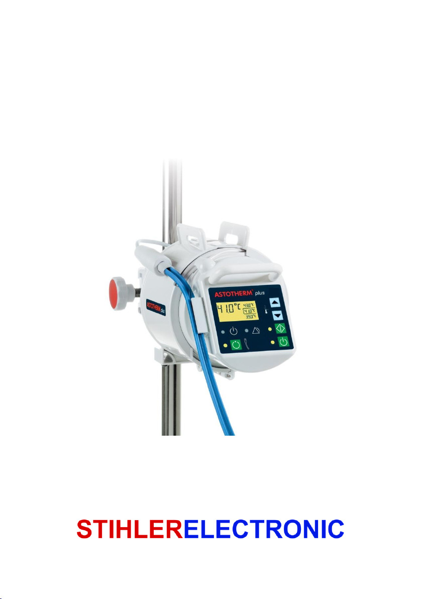
ASTOTHERM
plus
Warmer for Blood, Intravenous
Fluids and Irrigation Fluids
STIHLER ELECTRONIC GmbH • 70597 Stuttgart • Germany
Page 2

To be filled in by the user:
Serial number
Registration number
Device location
Start-up date
Manufacturer:
STIHLER ELECTRONIC GmbH
Julius-Hoelder-Strasse 36
70597 Stuttgart
GERMANY
Tel. +49 (0) 711-720670
Fax +49 (0) 711-7206757
www.stihlerelectronic.de
E-Mail: [email protected]
© 2017 STIHLER ELECTRONIC GmbH
STIHLER ELECTRONIC GmbH, Stuttgart, declares in sole responsibility that this
product (230 – 240 VAC models only) conforms to EC Directive 93/42/EEC on
medical devices.
Notified body: DEKRA Certification GmbH, registration number 0124.
Page 3

Contents
1 Information about these Instructions ............................................................................ 5
2 General information ........................................................................................................ 5
2.1 Guarantee conditions ................................................................................................... 5
2.2 Liability ......................................................................................................................... 5
2.3 Disposal of the equipment ........................................................................................... 6
2.4 Return of a used product ............................................................................................. 6
2.5 Service information ...................................................................................................... 6
3 Important safety information .......................................................................................... 7
3.1 Dangers ....................................................................................................................... 7
3.2 Warnings ..................................................................................................................... 7
3.3 Cautions .................................................................................................................... 11
3.4 Notices ....................................................................................................................... 12
4 Specification of application .......................................................................................... 13
4.1 Intended use .............................................................................................................. 13
4.2 Intended medical indication ....................................................................................... 13
4.3 Contraindications ....................................................................................................... 13
4.4 Possible adverse effects ................................................................ ............................ 13
4.5 Intended patient population ....................................................................................... 13
4.6 Intended user profile .................................................................................................. 13
4.7 Intended use/operation environment ......................................................................... 13
4.8 Intended part of the body/type of tissue ..................................................................... 14
5 Symbols ......................................................................................................................... 15
6 Product description ....................................................................................................... 17
6.1 Introduction ................................................................................................................ 17
6.2 Technical description ................................................................................................. 17
6.3 Components of the ASTOTHERM PLUS ................................................................... 21
6.4 Applied part ASTOLINE ............................................................................................. 22
6.5 Control panel ............................................................................................................. 23
7 Operating states ............................................................................................................ 25
7.1 Standby mode ........................................................................................................... 25
7.2 On mode .................................................................................................................... 26
7.3 Heating mode ............................................................................................................ 27
7.4 Increasing/Decreasing the setpoint temperature ....................................................... 28
7.5 ASTOLINE* On mode ................................................................................................ 29
7.6 ASTOLINE* Off mode ................................................................................................ 29
8 Installation ..................................................................................................................... 30
8.1 Initial start-up ............................................................................................................. 30
8.2 Installation of the warmer ........................................................................................... 30
9 Getting started ............................................................................................................... 31
9.1 Preparation for use .................................................................................................... 31
9.2 Inserting the infusion line, priming and starting the infusion ...................................... 34
9.3 After use .................................................................................................................... 38
9.4 Cleaning and disinfecting ........................................................................................... 39
Page 4

10 Alarms and troubleshooting ...................................................................................... 41
10.1 Low temperature alarm ........................................................................................... 42
10.2 Overheating alarm ................................................................................................... 43
10.3 Cable break alarm ................................................................................................... 44
10.4 ASTOLINE alarm (“S” models only) ........................................................................ 45
10.5 Processor alarm ...................................................................................................... 46
10.6 Standby mode - failure ............................................................................................ 47
11 Brief overview of operating states and alarms ......................................................... 48
11.1 Overview of operating states ................................................................................... 48
11.2 Overview of alarms ................................................................................................. 49
12 Maintenance ................................................................................................................ 50
12.1 Recurrent tests ........................................................................................................ 50
12.2 Set up for electrical tests ......................................................................................... 57
12.3 Test protocol ........................................................................................................... 58
13 Technical data ............................................................................................................. 60
14 Compliance with international standards ................................................................. 61
15 Ordering information, accessories and consumables ............................................ 62
16 Guidelines and manufacturer’s declaration ............................................................. 63
Page 5

1 Information about these Instructions
ASTOTHERM PLUS Instructions for Use
Carefully read the entire instructions for use before using the
device.
Correct and safe operation can only be guaranteed if the
instructions for use are observed.
Incorrect use can result in damage to the product or to other
property and/or personal injury.
Keep the instructions for use for future reference.
Only use the device for the intended purpose as described in
these instructions for use. Refer to chapter 4 Specification of
application.
1 Information about these Instructions
2 General information
2.1 Guarantee conditions
The guarantee period is 12 months. During this guarantee period the
manufacturer will repair or replace free of charge all defects caused as a result of
material or manufacturing errors.
Other damage is not subject to this guarantee. The guarantee does not include
cases of misuse or incorrect handling, use of force, or damage caused by normal
wear and tear. This applies also to changes undertaken by persons who are not
authorised by the manufacturer and to modifications to the original condition.
If the equipment is damaged during the guarantee period, send the cleaned
equipment to the nearest sales point or directly to STIHLER ELECTRONIC
GmbH. The sender is responsible for any transport and packaging costs.
2.2 Liability
The manufacturer is only liable for the safety, reliability and performance of the
equipment
if all operating, servicing, and calibration procedures have been carried out by
trained and qualified persons according to the procedures published by the
manufacturer;
if only original spare parts have been used to replace components as needed;
if assembly and repairs are only carried out by authorised personnel or an
authorised service centre;
if the electrical installations satisfy the locally applicable regulations and the
IEC/EN requirements and
if the equipment is used for its intended purpose and at a suitable location in
accordance with the instructions for use.
5
Page 6
ASTOTHERM PLUS Instructions for Use
2 General information
WARNING
Risk of infection!
Clean and disinfect the equipment after every use and before you return the
equipment for repairs.
NOTICE
The customer is responsible for the proper packaging and labelling of returns.
Follow the national regulations on the disposal of medical products.
2.3 Disposal of the equipment
Electrical devices are recoverable waste and should not be disposed of in
domestic waste at the end of their service life. Please follow the local rules for the
disposal of used products, or send the cleaned and disinfected equipment with a
corresponding note to STIHLER ELECTRONIC GmbH or your closest sales
point. This will ensure the most cost efficient and proper disposal of your old
equipment.
2.4 Return of a used product
A report must be sent together with the equipment, detailing the precise reasons,
circumstances, and, if known, the cause of the return. To prevent transportation
damage, the equipment should be shipped either in the original packaging or in
other, well-protected packaging.
2.5 Service information
For service or technical support, please contact your local sales point or the
following:
STIHLER ELECTRONIC GmbH Tel. +49 (0) 711-720670
Julius-Hoelder-Strasse 36 Fax +49 (0) 711-7206757
70597 Stuttgart www.stihlerelectronic.de
GERMANY E-Mail: [email protected]
6
Page 7
3 Important safety information
ASTOTHERM PLUS Instructions for Use
DANGER
DANGER indicates a hazardous situation which, if not avoided, will result in
death or serious injury.
WARNING
WARNING indicates a hazardous situation which, if not avoided, could result in
death or serious injury.
CAUTION
CAUTION indicates a hazardous situation which, if not avoided, may result in
minor or moderate injury.
NOTICE
NOTICE indicates a property damage message.
DANGER
Risk of explosion!
Do not use the ASTOTHERM PLUS in an environment at risk of explosion or in
the presence of flammable anesthetics.
WARNING
Risk of injury!
Use of the ASTOTHERM PLUS must be carried out under the supervision of
a physician.
Read and observe all instructions, stickers, and accompanying document-
ation enclosed with the medical device. Failure to observe the instructions,
including warnings and safety information, can result in incorrect handling,
patient injury, injury to users or medical personnel, damage to the device, or
material damage.
Operate and service this equipment only in accordance with the procedures
described in these instructions and with the applicable standards, rules, and
guidelines. The manufacturer shall not be responsible for the safety of users
or patients if any actions/procedures other than those published are carried
out during operation, servicing, or recurrent tests.
3 Important safety information
These Instructions for Use indicate and define the following safety information:
3.1 Dangers
3.2 Warnings
7
Page 8

ASTOTHERM PLUS Instructions for Use
3 Important safety information
WARNING
Risk of injury!
This device may only be operated by appropriately trained and medically
qualified healthcare professionals.
The service personnel must be appropriately trained and qualified.
Do not use the ASTOTHERM PLUS until the following error conditions have
been remedied through appropriate corrective action:
- Damaged or worn cables, plugs, or connecting socket.
- Damaged housing, damaged or loose control panel.
- Device has been exposed to mechanical impact / exposed to severe shock
or exposed to liquid.
- Alarm without knowing the cause.
- Damaged ASTOLINE („S“-models only), e.g. caused by clamps, scissors or
improper handling or storage.
- Damaged or missing markings/safety signs/warnings on the warmer and/or
ASTOLINE.
If the yellow “Alarm” LED and the acoustic alarm signal are not activated
automatically, when the device turns on by pressing the “Standby” Button,
remove the device from service immediately.
In the event of an overheating alarm proceed as outlined below:
1. Ensure that the ASTOTHERM PLUS safety system has deactivated the
heating function and that the temperature is dropping below 43°C. If the
temperature is not dropping, stop the treatment to prevent fluid from
returning to the patient. Remove the applicable tubing immediately from
the heat exchanger. Further evaluation should be carried out by
qualified medical personnel such as a physician before blood in the line
can be reinfused.
2. Consider the possible reasons for the alarm. For further information see
chapter 10 Alarms and troubleshooting. If in doubt, do not continue
using the warmer.
The mains cable should not touch the patient and should not hinder the
treating personnel.
The ASTOTHERM PLUS does not contain any parts the user can repair.
Therefore, do not attempt to repair the ASTOTHERM PLUS yourself.
Contact your local sales point.
Any repairs (such as, but not limited to, changing the power supply cord) to
the equipment may only be carried out by persons authorized and qualified
by the manufacturer.
Modifications to the device are not permitted.
8
Page 9
3 Important safety information
ASTOTHERM PLUS Instructions for Use
WARNING
Risk of overheating!
ASTOLINE („S“-models only) must hang freely while in use. Do not kink,
cover (not even partially), clamp (for example, with a surgical clamp) or roll
ASTOLINE.
Do not place ASTOLINE under or directly beside the patient. Heat build-up
can occur and/or the infusion extension can be squeezed off.
Do not kink or clamp ASTOLINE during storage, to avoid internal damage.
WARNING
Risk of haemolysis!
Make sure that the infusion line is not kinked.
WARNING
Risk of air embolism!
When fluids are warmed up, it is possible that gas may evolve (bubble form).
Be aware of the potential for air emboli when using a blood and fluid warmer.
Therefore prime all filters, lines and disposable sets before starting a treat-
ment.
Make sure all connections of the complete fluid stream are fixed tightly to
prevent fluid leakages and inadvertent infusion of air into the fluid stream.
Do not warm infusions containing soluted gas (e.g. bicarbonate).
Extreme care should always be taken to ensure that a bolus o fair does not
pass to the patient.
WARNING
Risk of infection!
Use aseptic procedures.
Clean and disinfect the warmer after every use and before you return the
warmer for repairs.
9
Page 10
ASTOTHERM PLUS Instructions for Use
3 Important safety information
WARNING
Risk of electric shock!
To avoid the risk of electric shock, this equipment must only be connected to
a supply mains with protective earth.
Do not use mains adapters that interrupt the earth conductor.
Do not open the ASTOTHERM PLUS housing.
If several pieces of equipment are combined or connected together (e.g., in
multiple socket outlets), the total leakage currents must not exceed the
allowable limits (refer to the respective national regulations). Observe the
requirements as stipulated in IEC/EN 60601-1 regarding medical electrical
systems.
All electrical installations must conform to the applicable electrical standards
and the specifications defined by the manufacturer.
Before every use, check to make sure that the ASTOTHERM PLUS and the
ASTOLINE are undamaged.
The mains plug must be removed from the socket to fully disconnect the
ASTOTHERM PLUS from the mains. WARNING
Risk of radio interference!
Use of this equipment adjacent to or stacked with other equipment should be
avoided because it could result in improper operation. If such use is
necessary, this equipment and the other equipment should be observed to
verify that they are operating normally.
Use of accessories, other than those specified or provided by the manufact-
urer of this equipment could result in increased electromagnetic emissions or
decreased electromagnetic immunity of this equipment and result in improper
operation.
Portable RF communications equipment (including peripherals such as
antenna cables and external antennas) should be used no closer than 30 cm
(12 inches) to any part of the ASTOTHERM PLUS, including cables specified
by the manufacturer. Otherwise, degradation of the performance of this
equipment could result.
10
Page 11
3 Important safety information
ASTOTHERM PLUS Instructions for Use
CAUTION
Risk of injury!
Federal law (USA) restricts this device to sale by or on the order of a
physician.
When fixing the warmer to a mounting device, pay attention to the max. load
to avoid tilting. Using normal infusion stands ASTOTHERM PLUS may be
mounted at a height of up to 165 cm. If you use the robust IV pole
ASTOSTAND, the device can be mounted up to 180 cm.
Use only approved infusion sets / infusion extensions (e. g. ASTOTUBE, see
chapter 15 Ordering information, accessories and consumables).
Damage to ASTOLINE can cause overheating, therefore follow the instructions
below:
Only disinfect ASTOLINE with alcohol-based agents or an approved
disinfectant.
Do not use solutions containing hypochlorite (bleach) for disinfecting
ASTOLINE.
Do not kink or pull excessively ASTOLINE.
Do not use any clamps or sharp instruments on ASTOLINE as damage to
ASTOLINE or the infusion line inside may result.
Use narrow plaster strips or other narrow, soft fixation methods (for example
cannula fixation, tube holder or Velcro®) to fix ASTOLINE.
Do not use cleaning and disinfection procedures which differ from the
procedure described.
CAUTION
Risk of hypothermia!
When ASTOTHERM PLUS is used, the patient’s body temperature must be
montitored at regular intervals.
The specified heating performance will only achieved by inserting the infusion
extension into the entire heat exchanger and, if applicable, in the entire length
of ASTOLINE.
The temperatur control of the ASTOTHERM PLUS controls and monitors the
current temperature of the heat exchanger, but not the patient’s body temperature.
If the ASTOTHERM PLUS cannot be started or if the patient's temperature
balance is insufficient, consider the use of alternative warming methods in
order to avoid or reduce hypothermia or to improve the patient's well-being.
3.3 Cautions
11
Page 12

ASTOTHERM PLUS Instructions for Use
3 Important safety information
CAUTION
Risk of needle dislodgement!
The weight of ASTOLINE („S“-models only) pulls on the patient’s infusion line.
Carefully secure the patient’s access against pulling. Attach the ASTOLINE by
suitable methods (e.g. tape, plaster or Velcro®).
CAUTION
Risk of radio interference!
The essential performance can be lost or degrated due to EM disturbances.
As a result, there is the possibility of hypothermia of the patient.
According to the standard IEC/EN 60601-1-2, medical electrical equipment
requires special precautions regarding electromagnetic compatibility (EMC)
and needs to be installed and put into service according the EMC information
provided.
This device/system may cause radio interference or may disrupt the operat-
ion of nearby devices. It may be necessary to take mitigation measures, such
as re-orienting or relocating of ASTOTHERM PLUS or shielding the location.
NOTICE
To avoid damage to the warmer:
- Do not immerse the warmer or ASTOLINE in liquid.
- Do not disinfect the warmer with these methods:
steam (autoclave)
hot air
thermo-chemical cleaning solutions.
- Refer to the specific instructions for use of the disinfectants.
To avoid damaging during storage, place ASTOLINE loosely around the
warmer and do not kink or clamp it. Use narrow plaster strips or other narrow,
soft fixation methods (for example cannula fixation, tube holder or Velcro®) to
fix ASTOLINE.
The customer is responsible for the proper packaging and labelling of returns.
Only the active insulation ASTOLINE must be connected to the appliance
socket of the “S” models.
3.4 Notices
12
Page 13

4 Specification of application
ASTOTHERM PLUS Instructions for Use
4 Specification of application
4.1 Intended use
ASTOTHERM PLUS is a warmer for Blood, Intravenous Fluids and Irrigation
Fluids. The application areas include blood transfusions, intravenous fluids,
dialysis, hemofiltration and apheresis.
4.2 Intended medical indication
The warming of medical fluids with ASTOTHERM PLUS supports the prevention
and therapy of hypothermia.
4.3 Contraindications
There are no known contraindications for warming blood, intravenous fluids and
irrigation fluids.
4.4 Possible adverse effects
When the ASTOTHERM PLUS is used as a warmer for return blood flow in a
haemofiltration, haemodialysis or haemodiafiltration device, it must be ensured
that the entire system meets the following:
The highest set temperature (43°C) must be used with care when operating at
low effluent flow rates (below 500 ml/h) for patients who weigh less than 30 kg.
Global positive heat balance and net patient warming may occur. If necessary,
operate the warmer at a reduced temperature setting.
4.5 Intended patient population
There are no restrictions for the intended patient group.
4.6 Intended user profile
The ASTOTHERM PLUS Warmer is to be operated only by medically qualified
and trained healthcare professionals.
4.7 Intended use/operation environment
The warmer may only be used in professional healthcare facilities (e.g. hospital,
emergency care, dialysis, including HF surgical equipment, etc.).
The warmer is not intended for home healthcare environment.
The warmer is reusable, but requires cleaning / disinfection between the
applications.
Appropriate medical hygienic factors must be applied for the use of the warmer.
The warmer must not be used in an environment at risk of explosion or in the
present of flammable anesthetics.
13
Page 14

ASTOTHERM PLUS Instructions for Use
4 Specification of application
4.8 Intended part of the body/type of tissue
The warmer is used to warm blood or other medical fluids supplied to the body.
The fluids are physically separated from the warmer by disposable parts (tubes).
The optional applied part ASTOLINE may have skin contact.
14
Page 15
5 Symbols
ASTOTHERM PLUS Instructions for Use
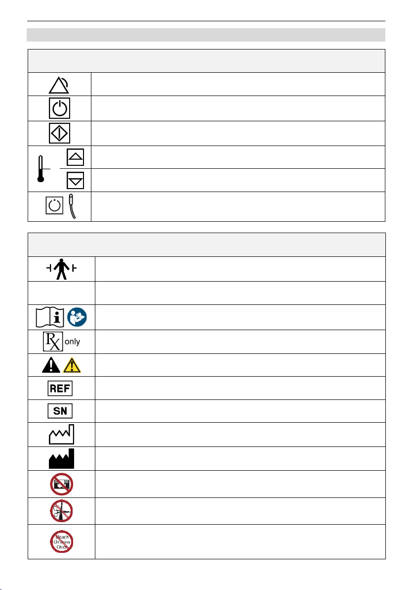
Symbols, used on the Control Panel
Alarm condition if the yellow “Alarm” LED lights
“Standby” button.
The Warmer is in Standby Mode if the blue LED is on
“Start” button.
The Warmer is in Heating Mode, if the green LED is on
“Increase” button increases the setpoint temperature
“Decrease” button decreases the setpoint temperature
“ASTOLINE” button for switching On/Off the active insulation
Where these symbols are applicable, they appear at the relevant point on the
device, the package, the rating plate or in the accompanying paperwork.
Defibrillation-proof type B applied part in accordance with
IEC/EN 60601-1
IPX 4
Splash proof in accordance to IEC/EN 60529
Refer to instructions for use! / Follow instructions for use!
Caution: Federal US law restricts this device to sale by or on
order of a physician.
General warning sign
Catalogue number
Serial number
Year of manufacture
Manufacturer
Prohibition: Do not cover the active insulation ASTOLINE – risk
of overheating!
Prohibition: Do not clamp the active insulation ASTOLINE – risk
of damage and possible overheating!
Prohibition: Do not disinfect the active insulation ASTOLINE
with Hypochlorite solution – risk of damage and possible
overheating!
5 Symbols
15
Page 16
ASTOTHERM PLUS Instructions for Use
5 Symbols
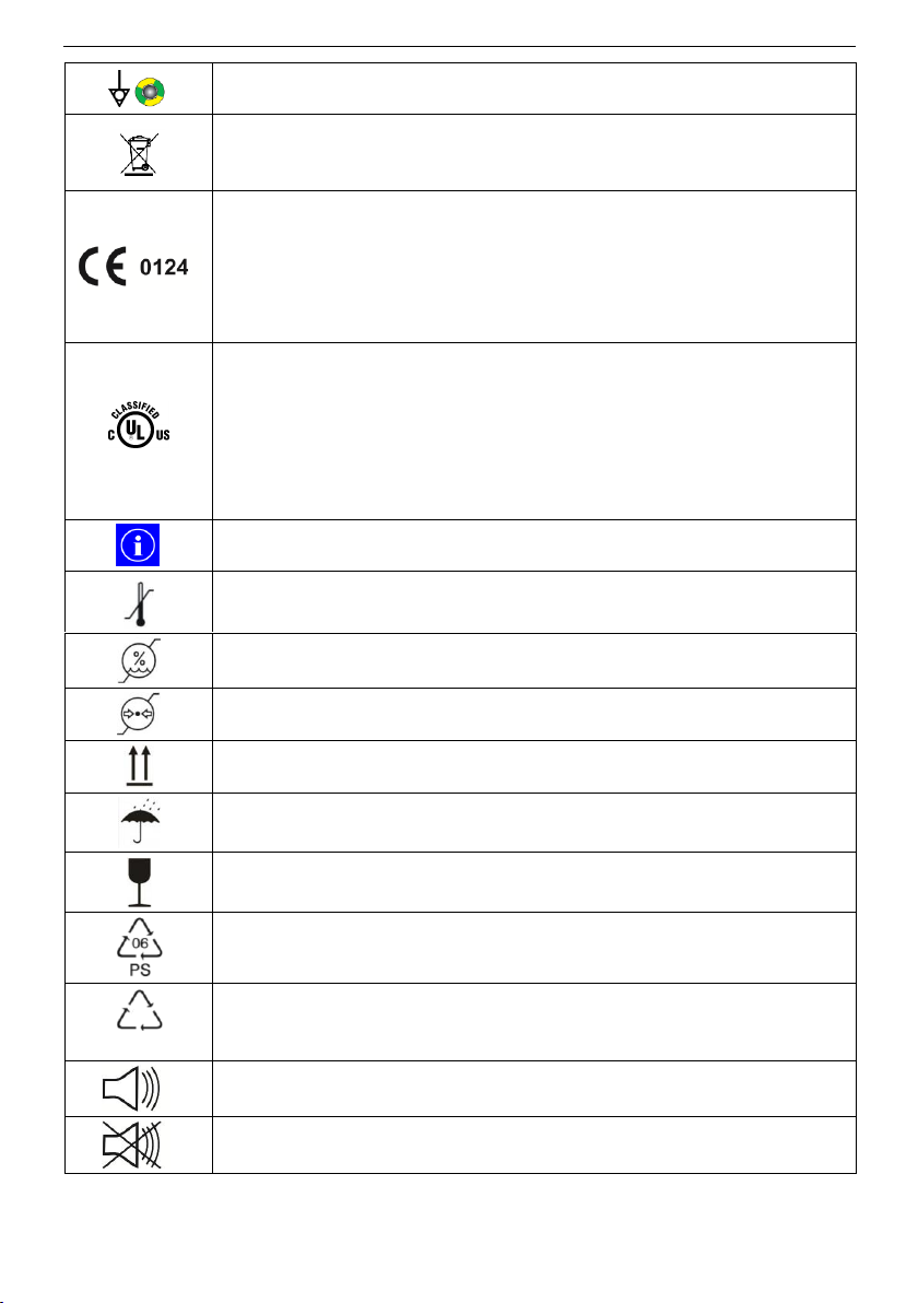
Symbol at the connector for potential equalization according
IEC/EN 60601-1
Electrical devices are valuable products and should not be
thrown in dustbin when the reach the end of their serviceable
life.
The device is conform to the MDD 93/42/EEC dated 14th June
1993 for medical devices. The Notified Body DEKRA
Certifications GmbH (Reg. No. 0124) monitors the quality
system of the manufacturer. The CE mark applies only to the
ASTOTHERM PLUS Warmer. Disposable parts (e.g. infusion
sets) suitable for use with this device have their own approvals.
75JA
MEDICAL – GENERAL MEDICAL EQUIPMENT AS TO
ELECTRICAL SHOCK, FIRE AND MECHANICAL HAZARDS
ONLY IN ACCORDANCE WITH standards
ANSI/AAMI ES60601-1:2005/(R)2012 and A1:2012),
C1:2009/(R)2012 and A2:2010/(R):2012
CAN/CSA-C22.2 No. 60601-1:2014.
Control No. 75JA
This symbol indicates additional information.
Indicates the temperature range within which the package must
be stored and handled.
Indicates the ambient humidity range within which the package
must be stored and handled.
Indicates the pressure range within the package must be stored
and handled.
Indicates the upright position of the package
The package must be kept in a dry environment.
The contents of the package are fragile and must therefore be
handled with care. Do not drop or throw.
Recyclable - Polystyrene (acc. GB 18455-2001)
CB
Recyclable - Cardboard (acc. GB 18455-2001)
Acoustic alarm signal
No acoustic alarm signal
16
Page 17

6 Product description
ASTOTHERM PLUS Instructions for Use
6 Product description
6.1 Introduction
ASTOTHERM PLUS consists of a stand-alone Warmer and optionally of the
additional active insulation ASTOLINE („S“-models).
ASTOTHERM PLUS is a device for specific heating of blood and fluids which are
delivered to the patients by transfusion, infusion or irrigation. The warming of the
liquid supports the prevention and therapy of hypothermia during or after surgery;
during longer procedures such as dialysis, hemofiltration, or apheresis the warming leads to a well-being. The applications of the ASTOTHERM PLUS therefore
include transfusion, infusion, dialysis, hemofiltration and apheresis.
The ASTOTHERM PLUS Warmer can be used to warm fluids administered to a
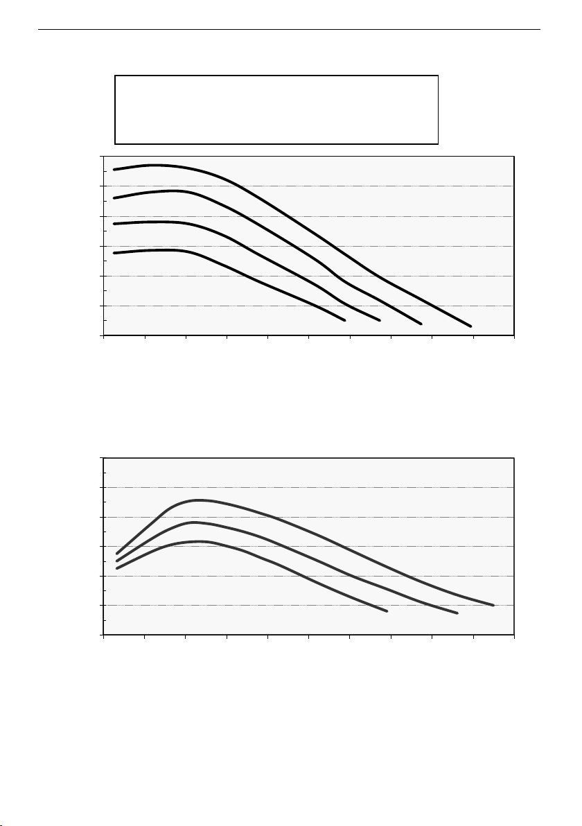
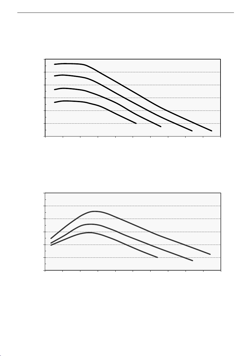
patient at flow rates of 0 to 6000 ml/h (i.e. 0 to 100 ml/min), see figures 1 to 4.
In the case of low flow rates, the re-cooling of the heated fluid on the way from
the warmer to the patient is limited by using the active insulation ASTOLINE („S“
models only). The heated flexible silicone body surrounds the infusion extension
on the way to the patient, ensuring that the part of the infusion line which would
otherwise be exposed to cool ambient air is insulated and heated. Its special
shape also enables infusions and transfusions to be observed all the way to the
patient.
The active insulation ASTOLINE and the infusion extension ASTOTUBE are
considered as applied part acc. to IEC/EN 60601-1.
6.2 Technical description
During operation of the Warmer heat is transferred from the internal heating
element to the heat exchanger. Infusion extensions can simply be inserted in the
circumferential groove. The heat from the heat exchanger is transferred through
the inserted infusion extension to the fluid to be warmed.
The temperature of the heat exchanger is monitored by a microprocessor
controlled temperature control system and by two independent alarm systems
designed to alert the operator to failure conditions and, if necessary, to switch off
the heating process automatically in the event of excessively high temperatures.
During operation, the mean temperature of the heat exchanger is displayed; this
is not equal to the temperature of the medium to be warmed. ASTOTHERM
PLUS neither regulates nor monitors/displays the current temperature of the
medium to be warmed. The temperature of the medium (fluid) depends on a
variety of factors, such as, but not limited to additional factors:
Room temperature and ventilation
Inlet temperature of the fluid (warmed-up or cold)
Flow rate
The heat protection sleeve (option) protects infusions from the effects of external
cold (e.g. air condition) and prevents heat being given off into the room.
17
Page 18
ASTOTHERM PLUS Instructions for Use
6 Product description
CAUTION
Risk of hypothermia!
When ASTOTHERM PLUS is used, the patient’s body temperature must be
montitored at regular intervals.
The specified heating performance will only achieved by inserting the infusion
extension into the entire heat exchanger and, if applicable, in the entire length
of ASTOLINE.
The temperature control of the ASTOTHERM PLUS controls and monitors
the current temperature of the heat exchanger, but not the patient’s body
temperature.
If the ASTOTHERM PLUS cannot be started or if the patient's temperature
balance is insufficient, consider the use of alternative warming methods in
order to avoid or reduce hypothermia or to improve the patient's well-being.
18
Page 19
6 Product description
ASTOTHERM PLUS Instructions for Use
32
34
36
38
40
42
44
0 10 20 30 40 50 60 70 80 90 100
Temperature [°C]
Flow [ml/min]
SET: 37°C
39°C
41°C
43°C
32
34
36
38
40
42
44
0 10 20 30 40 50 60 70 80 90 100
Temperature [°C]
Flow [ml/min]
43°C
41°C
SET: 39°C
10 ml/min = 0,6 l/h 60 ml/min = 3,6 l/h
20 ml/min = 1,2 l/h 70 ml/min = 4,2 l/h
30 ml/min = 1,8 l/h 80 ml/min = 4,8 l/h
40 ml/min = 2,4 l/h 90 ml/min = 5,4 l/h
50 ml/min = 3,0 l/h 100 ml/min = 6,0 l/h
Typical temperature curves are shown in the following figures.
Fig. 1: Fluid outlet temperature (device outlet) at 10°C inlet temperature
model AP220 without ASTOLINE
Fig. 2: Fluid outlet temperature (patient connection) at 20°C inlet temperature
model AP220S with ASTOLINE
19
Page 20
ASTOTHERM PLUS Instructions for Use
6 Product description
32
34
36
38
40
42
44
0 10 20 30 40 50 60 70 80 90 100
Temperature [°C]
Flow [ml/min]
43°C
41°C
39°C
SET: 37°C
32
34
36
38
40
42
44
0 10 20 30 40 50 60 70 80 90 100
Temperature [°C]
Flow [ml/min]
43°C
41°C
SET: 39°C
Fig. 3: Fluid outlet temperature (device outlet) at 20°C inlet temperature
Fig. 4: Fluid outlet temperature (patient connection) at 20°C inlet temperature
20
model AP260 without ASTOLINE
model AP260S with ASTOLINE
Page 21
6 Product description
ASTOTHERM PLUS Instructions for Use
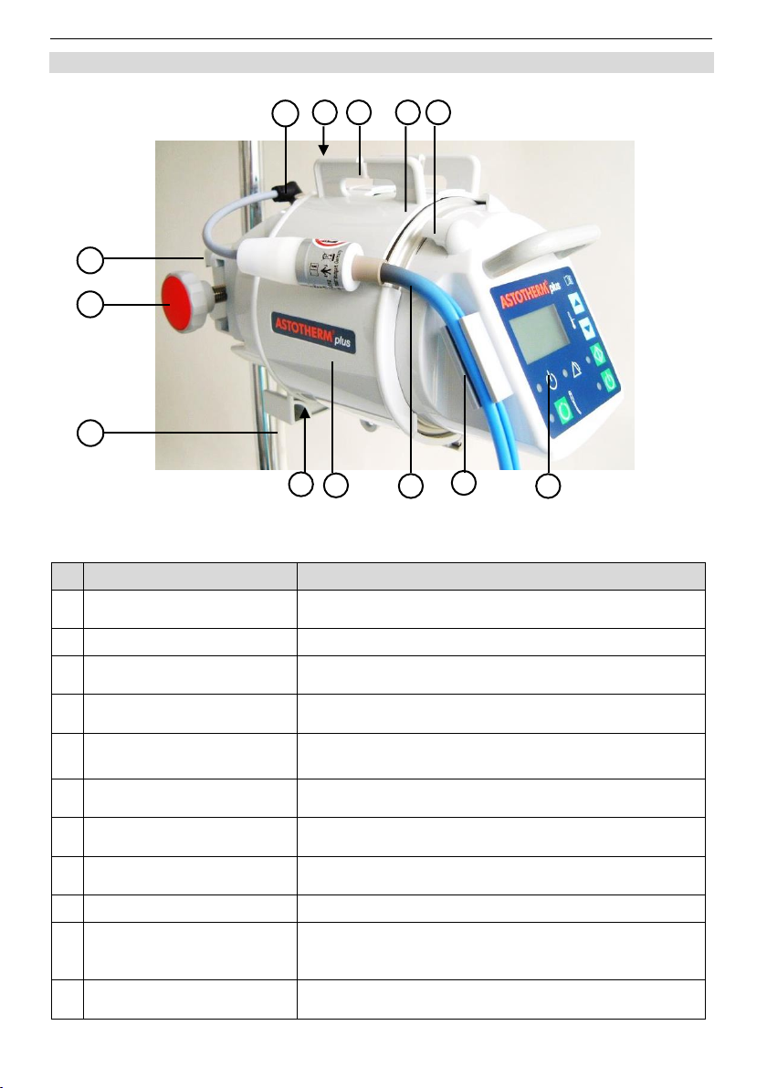
#
Item
Description
1
Control Panel
Control buttons and displays.
(s. chapter 6.5 Control panel)
2
Bracket*
Fixes ASTOLINE*
3
ASTOLINE*
Active insulation of the infusion extension up to the
patient (s. a. figure 6).
4
Heat Protection Sleeve**
Reduces the effect of environment and minimizes the
radiation of heat.
5
Screw with Star Grip
For adapting the attachment device to infusion stands
of different diameters.
6
Universal Attachment
Device
Attaches the warmer to infusion stands (Ø 12 to
35 mm) or medical rails.
7
Appliance socket*
Electrical connection of the active insulation
ASTOLINE.
8
Tube holder rear
Fixes the infusion extension at the entry point (from
the liquid container).
9
Sleeve grips
To open / close the heat protection sleeve**
10
Heat exchanger
(under sleeve)
Transfers heat from the internal heating element
through the inserted infusion extension to the medium
to be heated.
11
Tube holder front
Fixes the infusion extension at the exit point (to the
patient or to ASTOLINE*).
7 6 5
8 9 10
11 1 2
3 4 12
13
6.3 Components of the ASTOTHERM PLUS
Fig. 5: ASTOTHERM PLUS (AP220S)
21
Page 22
ASTOTHERM PLUS Instructions for Use
6 Product description
#
Item
Description
12
Connector for Potential
Equalization**
The purpose of additional potential equalization is to
equalize potentials between different metal parts that
can be touched simultaneously, or to reduce
differences of potential which can occur during
operation between the body, the medical electrical
devices and conductive parts of other objects.
The connection is made by green-yellow insulated
leads (min. 4 mm²) to standardized plug connectors
and receptacles.
When connecting/combining medical electrical
equipment together to a medical electrical system, the
requirements of IEC/EN 60601-1 must be observed.
13
Power Supply Cord with
Mains Plug
Conveys electricity from the wall power supply to the
device. Pull the mains plug to disconnect from supply
network.
#
Item
Description
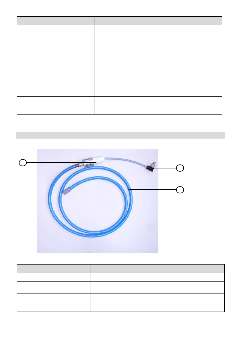
1
Adapter
Connection between silicone jacket and cable.
2
Appliance plug
For electrical connection of ASTOLINE* to the Warmer
ASTOTHERM PLUS.
3
Flexible silicone jacket
Molded groove takes the infusion extension up to a
length of 130 cm and protects the heated liquid from
cooling on its way from the warmer to the patient.
*„S“ models only, **optional
6.4 Applied part ASTOLINE
Fig. 6: Active insulation ASTOLINE*
*„S“ models only
22
Page 23
6 Product description
ASTOTHERM PLUS Instructions for Use
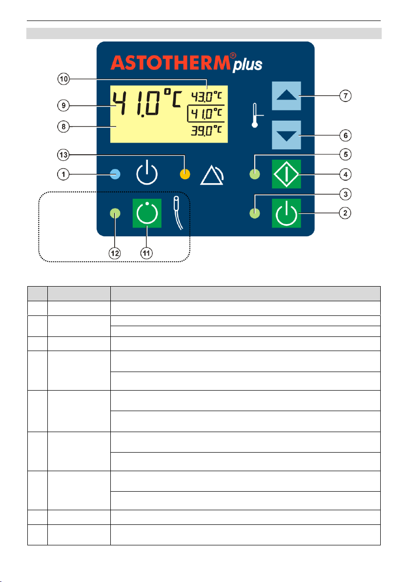
#
Item
Description
1
“Standby” LED
Illuminates blue when the warmer is in Standby Mode.
2
“Standby”
button”
Turns the warmer from Standby Mode to On Mode.
Turns the warmer from any Mode to the Standby Mode.
3
“On” LED
Illuminates green when the warmer is in On Mode.
4
“Start” button
Starts the heating process while the device is in On Mode or Alarm
Mode.
Starts test 6 (see chapter 12.1 Recurrent tests), when the warmer is
operated with the middle setpoint temperature.
5
“Start” LED
Flashes green when the device is in On Mode (heating is not yet
started).
Illuminates green when the device is in Heating Mode (“Start”
button has been pressed).
6
“Decrease”
button
Selection of the next lower setpoint temperature. The frame
indicates the selected temperature.
Starts test 8 (see chapter 12.1 Recurrent tests), when the warmer is
operated with the lowest setpoint temperature.
7
“Increase”
button
Selection of the next higher setpoint temperature. The frame
indicates the selected temperature.
Starts test 7 (see chapter 12.1 Recurrent tests), when the warmer is
operated with the highest setpoint temperature.
8
LCD Display
Informs the user about temperatures, test and fault conditions.
9
Actual
Temperature
Displays the current temperature of the heat exchanger.
„S“models only
6.5 Control panel
Fig. 7: Control panel
23
Page 24

ASTOTHERM PLUS Instructions for Use
6 Product description
#
Item
Description
10
Setpoint
Temperatures
Shows the three possible setpoint temperatures. The frame
indicates the selected temperature.
11*
“ASTOLINE“
button
Switches ASTOLINE on / off when the warmer is in On Mode.
12*
“ASTOLINE“
LED
Illuminates green, when ASTOLINE is switched on.
13
“Alarm“ LED
Lights yellow if an alarm condition exists.
*„S“ models only
The following section provides further information about the operating states. This
includes a description of the actions of the user and the device responses of each
operating state.
24
Page 25
7 Operating states
ASTOTHERM PLUS Instructions for Use
7.1 Standby mode
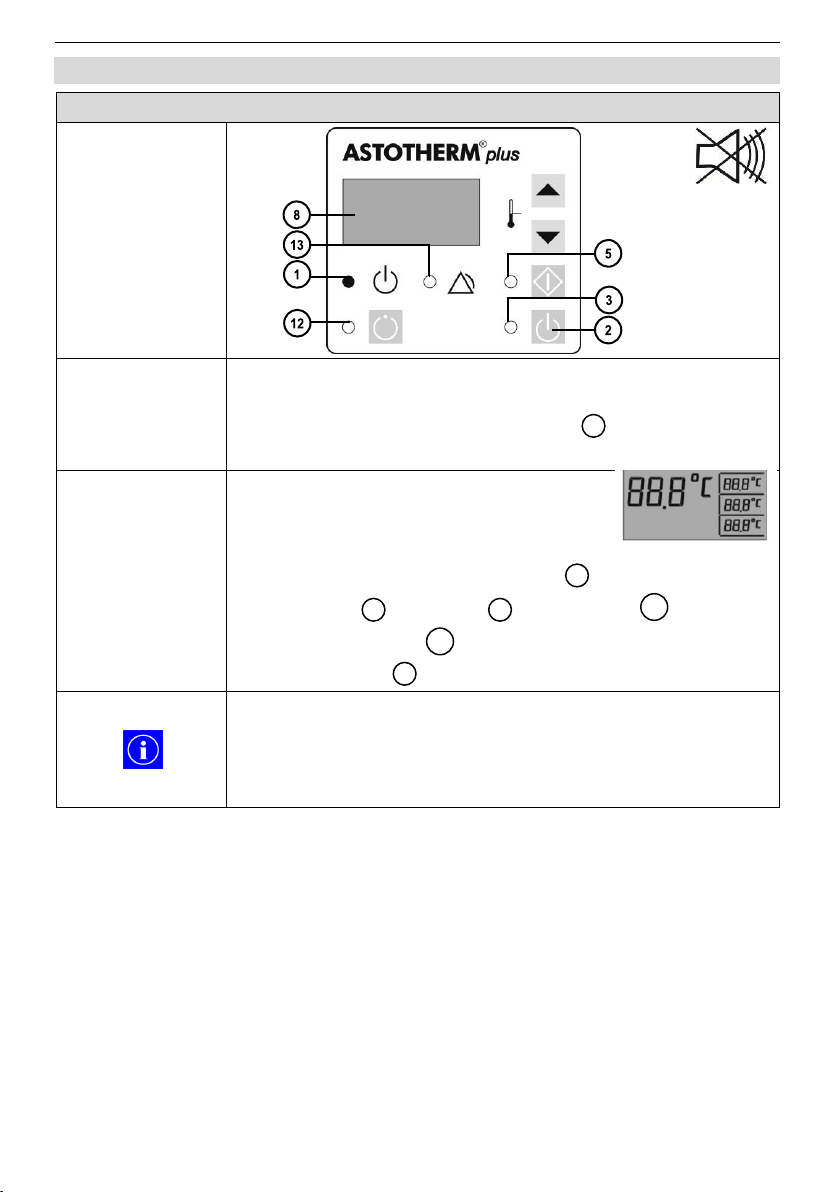
Control Panel
Action
When the mains cable is plugged into the socket, the device
is in Standby Mode.
Alternately, press the “Standby” button to switch the
device from any Mode to Standby Mode.
Device response
When plugging in the power cord briefly
all segments of the display and all LEDs
turn on, then
all segments of the display turn off .
“Start” LED , “On” LED , “Alarm” LED and
“ASTOLINE” LED* turn off.
“Standby” LED turns on.
After a prolonged power failure (> 5 sec), the device
automatically switches to Standby Mode.
In Standby Mode, only the electronic is disconnected
from the power supply. The Warmer remains connected to
the mains.
2 8 5
3
13
12
1
7 Operating states
*„S“ models only
25
Page 26
ASTOTHERM PLUS Instructions for Use
7 Operating states
7.2 On mode
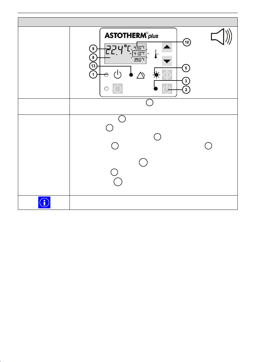
Control Panel
Action
Press the “Standby” button to switch the device from
Standby Mode to On Mode.
Device response
“Standby” LED turns off.
“On” LED turns on.
The backlight of the display lights up.
The display shows the current temperature (eg.
22.4°C) of the heat exchanger and the available range of
setpoint temperatures . The selection frame is flashing.
“Start” LED flashes.
„Alarm” LED lights
Acoustic alarm signal beeps.
As long as the temperature of the heat exchanger is below
15°C, the display shows “- - -”.
2 1 3 8 8
9
10 5 13
26
Page 27
7 Operating states
ASTOTHERM PLUS Instructions for Use
7.3 Heating mode
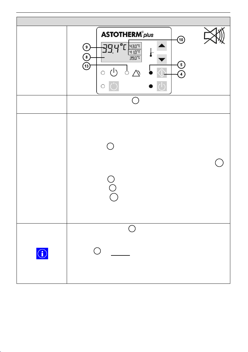
Control Panel
Action
Press the “Start” button at least for one second to switch
the warmer from On Mode to Heating Mode.
Device response
While the button is pressed, a self-test is performed.
During this test the safety cut offs are activated to verify
their safe function. The brief clicking of the relay can be
heard.
“Start” LED turns on.
Acoustic alarm signal stops.
The heater is activated until the setpoint temperature
(indicated by the frame) is reached.
The display shows the increasing current
temperature of the heat exchanger (e.g. 39.4°C).
“Alarm” LED lights until the setpoint temperature has
exceeded (during heating up) the tripping limit of the Low
Temperature Alarm (see chapter 10.1 Low temperature
alarm).
If the “Start” button“ is not pressed long enough, the
self-test cannot be completed and the warmer will not
start. Then repeat the procedure and press the “Start”
button for at least one second.
After a short power failure (< 5 seconds), and after return
of the power supply, the warmer resumes operation again
to the setpoint temperature which was previously
selected.
4
5
10
8
9
13
4
27
Page 28

ASTOTHERM PLUS Instructions for Use
7 Operating states
7.4 Increasing/Decreasing the setpoint temperature
Control Panel
Action
1. Briefly press the “Increase” button or “Decrease”
button , while the device is turned on (On Mode) or
started (Heating Mode) to change the setpoint
temperature within the three indicated temperatures.
2. Confirm the new setpoint temperature within 5 seconds by
pressing the “Start” button .
Device response
The flashing frame indicates the selected setpoint
temperature .
“Start” LED flashes green until to the confirmation with
the “Start” button .
After confirmation the “Start” LED lights green and the
frame marks the currently selected setpoint
temperature .
The displayed actual temperature rises or falls
according to the selection.
If the newly selected setpoint temperature is not confirmed
within 5 seconds by pressing the “Start” button , the
temperature regulation continues working with the initial
setpoint temperature.
During operation, the mean temperature of the heat
exchanger is displayed; this is not equal to the temperature of the medium to be warmed. ASTOTHERM PLUS
neither regulates nor monitors/displays the current
temperature of the medium to be warmed.
7 6 4
10
5 4 5
10
9
4
28
Page 29
7 Operating states
ASTOTHERM PLUS Instructions for Use
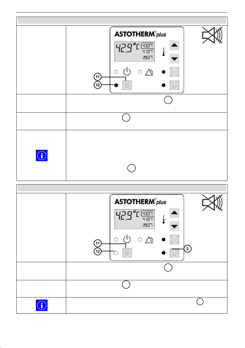
7.5 ASTOLINE* On mode
Control Panel
Action
Briefly press the “ASTOLINE” button while the device is
in On Mode or Heating Mode.
Device response
“ASTOLINE” LED turns on green.
The active insulation ASTOLINE slowly warms up.
If no heat is taken away from the Warmer (e.g. at high
ambient temperature and stagnant liquid or low flow or when
lowering the setpoint temperature) the heating element of
ASTOLINE is switched off automatically after appr. 4.5
minutes, and ASTOLINE cools down.
The “ASTOLINE” LED continues lighting. With recurrent
heat demand ASTOLINE is reconnected automatically.
7.6 ASTOLINE* Off mode
Control Panel
Action
Briefly press the “ASTOLINE” button while the device is
in ASTOLINE On Mode.
Device response
“ASTOLINE” LED turns off.
The active insulation ASTOLINE cools down slowly.
Turning off the Warmer with the “Standby” button
automatically causes the shutdown of ASTOLINE.
11
12
12
11
12
*„S“ models only
29
Page 30

ASTOTHERM PLUS Instructions for Use
8 Installation
8 Installation
8.1 Initial start-up
Prior to first use, perfom the following inspections:
Visual inspection (s. chapter 12.1 Recurrent tests)
Check the mains voltage (compare the details on the type label with the
available mains voltage.) An incorrect mains voltage may destroy the
National regulations may require different inspections for the initial start-up. If
additional tests are required for electrical safety, these must be carried out
according to chapter 12.1 Recurrent tests, 12.2 Set up for electrical tests and
12.3 Test protocol.
8.2 Installation of the warmer
For safe installation, the warmer is equipped with a universal attachment device.
With this, the device can be securely attached to infusion stands as well as to
medical standard rails.
8.2.1 Attachment to infusion stands/rods
1. Turn the handwheel counterclockwise to open the attachment device.
2. Select a maximum height of 165 cm (ASTOSTAND: 180 cm) at the infusion
3. Turn the handwheel clockwise to lock the attachment device to the infusion
4. Check that the warmer is firmly fixed.
8.2.2 Attachment to medical rails
1. Unscrew the small knurled screw on the bottom of the attachment device.
2. Hang the warmer obliquely from above with the attachment device into the
3. Fix the heater by tightening the small knurled screw to the standard rail.
4. Check that the warmer is firmly fixed.
equipment.
stand and place the open clamping area of the attachment device on the
infusion stand.
stand.
standard rail.
30
Page 31
9 Getting started
ASTOTHERM PLUS Instructions for Use
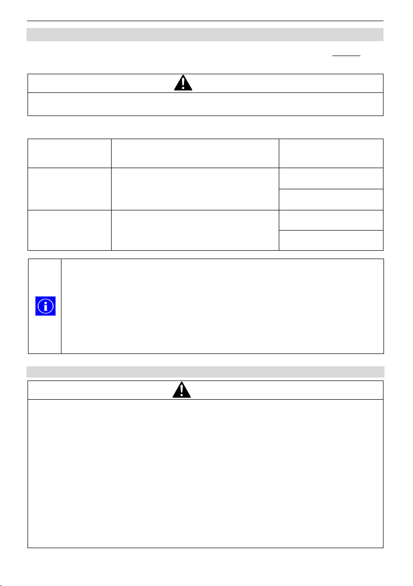
CAUTION
Risk of injury!
Use only approved infusion sets / infusion extensions.
ASTOTUBE
Order No.
Description
Suitable for model
IFT 30460
Sterile infusion extension made from PVC,
outer diameter Ø 4 mm, length 575 cm.
Filling volume approx. 40 ml
AP220
AP220S
IFT 30410
Sterile infusion extension made from PVC,
outer diameter Ø 6.8 mm, length 490 cm.
Filling volume approx. 89 ml
AP260
AP260S
WARNING
Risk of injury!
Do not use the ASTOTHERM PLUS until the following error conditions have
been remedied through appropriate corrective action:
- Damaged or worn cables, plugs, or connecting socket.
- Damaged housing, damaged or loose control panel.
- Device has been exposed to mechanical impact / exposed to severe shock
or exposed to liquid.
- Alarm without knowing the cause.
- Damaged ASTOLINE („S“-models only), e.g. caused by clamps, scissors or
improper handling or storage.
- Damaged or missing markings/safety signs/warnings on the warmer and/or
ASTOLINE.
To achieve the greatest possible benefit, ASTOTHERM PLUS should
be set up close enough to the patient so that the end of the active
insulation ASTOLINE* reaches up to the point of injection.
ASTOTHERM PLUS and ASTOLINE* should be switched on before
use so that ASTOLINE* has time to heat up.
Do not position the device in a manner that is difficult to disconnect it
from mains by the mains plug.
*„S“ models only
9 Getting started
Getting started is grouped into 4 sections. Read through each section before
performing a procedure.
ASTOTUBE is the original CE-marked accessory for ASTOTHERM PLUS.
9.1 Preparation for use
31
Page 32

ASTOTHERM PLUS Instructions for Use
9 Getting started
WARNING
Risk of injury!
Use of the ASTOTHERM PLUS must be carried out under the supervision of
a physician.
The mains cable should not touch the patient and should not hinder the
treating personnel.
CAUTION
Risk of injury!
When fixing the Warmer to a mounting device (e.g. IV pole) pay attention to the
max. safe working load and tipping stability. Using normal infusion stands
ASTOTHERM PLUS may be mounted at a height of up to165 cm. If you use
the robust IV pole ASTOSTAND, the device can be mounted up to 180 cm.
WARNING
Risk of injury!
If the yellow "Alarm” LED and the acoustic alarm are not activated automatically when the device turns on by pressing the “Standby” button, remove the
device from service immediately.
1. Attach ASTOTHERM PLUS to an IV pole or to a medical standard rail using
the attachment device according to chapter 8.2 Installation of the warmer.
2. Plug the mains plug into a socket.
The blue “Standby” LED turns on, the device is in Standby Mode.
3. Press the “Standby” button to switch ASTOTHERM PLUS to On Mode.
The blue “Standby” LED turns off and the green “On” LED turns on.
4. Check the audible and visual indicators and the display:
The acoustic alarm signal beeps and the “Alarm” LED lights yellow.
The „Start” LED flashes green and the display shows the actual
temperature of the heat exchanger and the available setpoint temperatures.
5. Press the “Increase” button or the “Decrease” button to select a
different setpoint temperature, if necessary.
32
Page 33
9 Getting started
ASTOTHERM PLUS Instructions for Use
Any change of the setpoint temperature must be confirmed within 5
seconds by pressing the „Start” button, otherwise the warmer uses the
previously selected setpoint temperature.
As long as the temperature of the heat exchanger is below 15°C, the
display shows “- - -“.
As long as the actual temperature is below the trigger temperature of
the low temperature alarm (4°C lower than the selected setpoint
temperature), the “Alarm” LED lights yellow.
The setpoint temperature can be changed during operation at any time
following chapter 7.4 Increasing/Decreasing the setpoint
temperature.
NOTICE
Only the active insulation ASTOLINE must be connected to the appliance
socket of the „S“ models.
Do not rotate the angled connector housing of ASTOLINE in the inserted
state. This can cause damage to appliance plug and/or socket.
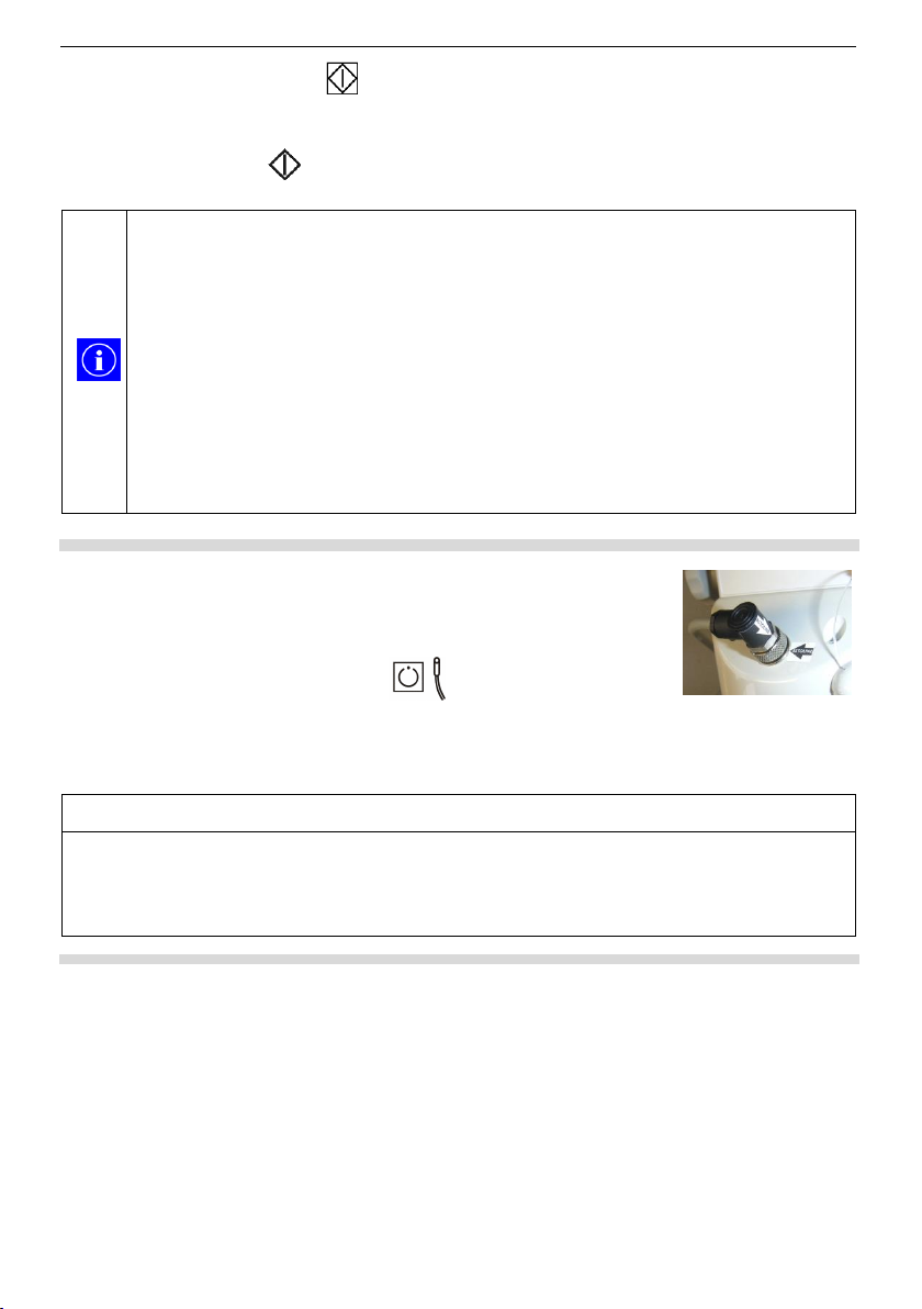
Fig. 8: Connection of
ASTOLINE
6. Press the “Start” button for at least one second to switch ASTOTHERM
PLUS to Heating Mode.
While the button is pressed, the clicking of the self-test can be heard.
The “Start” LED illuminates green.
,
Only for „S“ models:
7. Connect the plug of ASTOLINE to the appliance socket on
the rear housing part (the correct alignment is marked with
arrows, s. fig 8).
8. Press the “ASTOLINE” button to switch on
ASTOLINE.
The “ASTOLINE” LED illuminates green and ASTOLINE
heats up slowly.
33
Page 34
ASTOTHERM PLUS Instructions for Use
9 Getting started
WARNING
Risk of air embolism!
Be aware of the potential for air emboli when using a blood and fluid warmer.
Therefore prime all filters, lines and disposable sets before starting a
treatment.
Make sure all connections of the complete fluid stream are fixed tightly to
prevent fluid leakages and inadvertent infusion of air into the fluid stream.
When fluids are warmed up, it is possible that gas may evolve (bubble form).
Do not warm infusions containing soluted gas (e.g. bicarbonate).
Extreme care should always be taken to ensure that a bolus of air does not
pass to the patient.
WARNING
Risk of infection!
Use aseptic procedures.
WARNING
Risk of haemolysis!
Make sure that the infusion line is not kinked.
CAUTION
Risk of hypothermia!
When ASTOTHERM PLUS is used, the patient’s body temperature must be
montitored at regular intervals.
The specified heating performance will only achieved by inserting the infusion
extension into the entire heat exchanger and, if applicable, in the entire length
of ASTOLINE.
The temperatur control of the ASTOTHERM PLUS controls and monitors the
current temperature of the heat exchanger, but not the patient’s body
temperature.
If the ASTOTHERM PLUS cannot be started or if the patient's temperature
balance is insufficient, consider the use of alternative warming methods in
order to avoid or reduce hypothermia or to improve the patient's well-being.
Pressure losses can occur when infusion extensions are used
(depending on tube dimensions and flow rate).
9.2 Inserting the infusion line, priming and starting the infusion
34
Page 35
9 Getting started
ASTOTHERM PLUS Instructions for Use
Fig. 9: Inserting the infusion extension (start)
Fig. 9: Inserting of the infusion extension (continuation)
9-A
9-B
9-C
1. Detach the heat protection sleeve (optional) by gently pulling apart the two
grips.
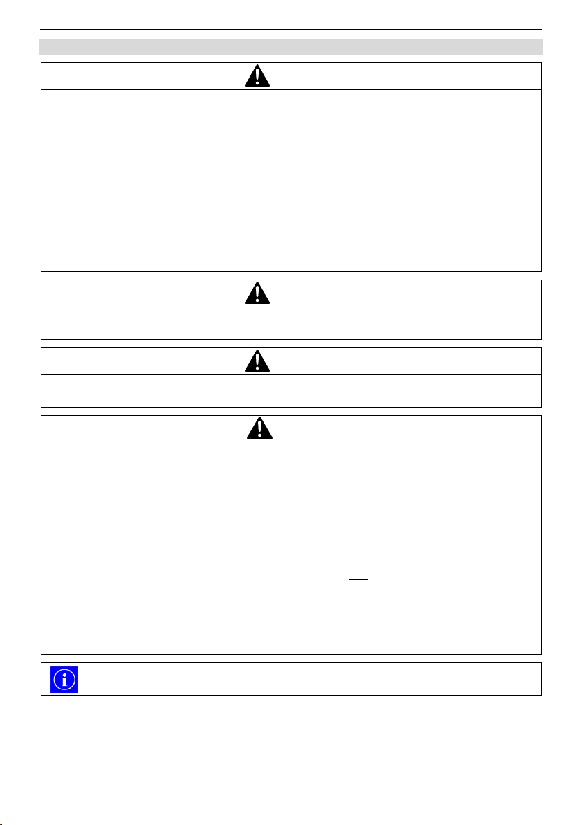
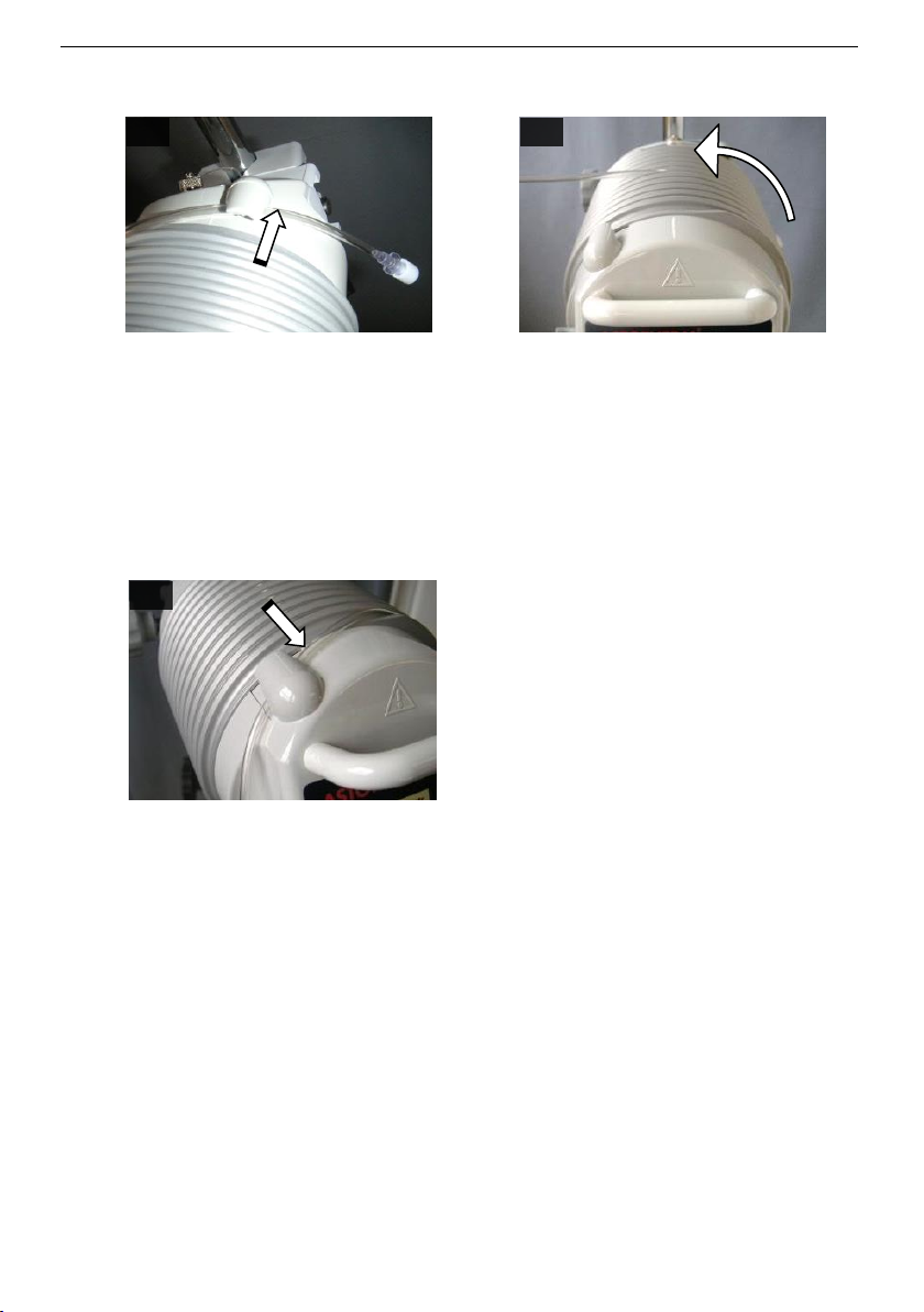
2. Clip the IV end of the infusion extension (female Luer Lock) into the rear tube
holder (fig. 9-A).
3. Starting from the back, wind and insert the infusion extension in a counter
clockwise direction up and around into the circumferential groove of the heat
exchanger (fig. 9-B). Gently pulling makes it easier to insert and improves the
seating of the infusion extension.
4. After leaving the last circulation, clip the infusion extension into the front tube
holder (fig. 9-C).
35
Page 36
ASTOTHERM PLUS Instructions for Use
9 Getting started
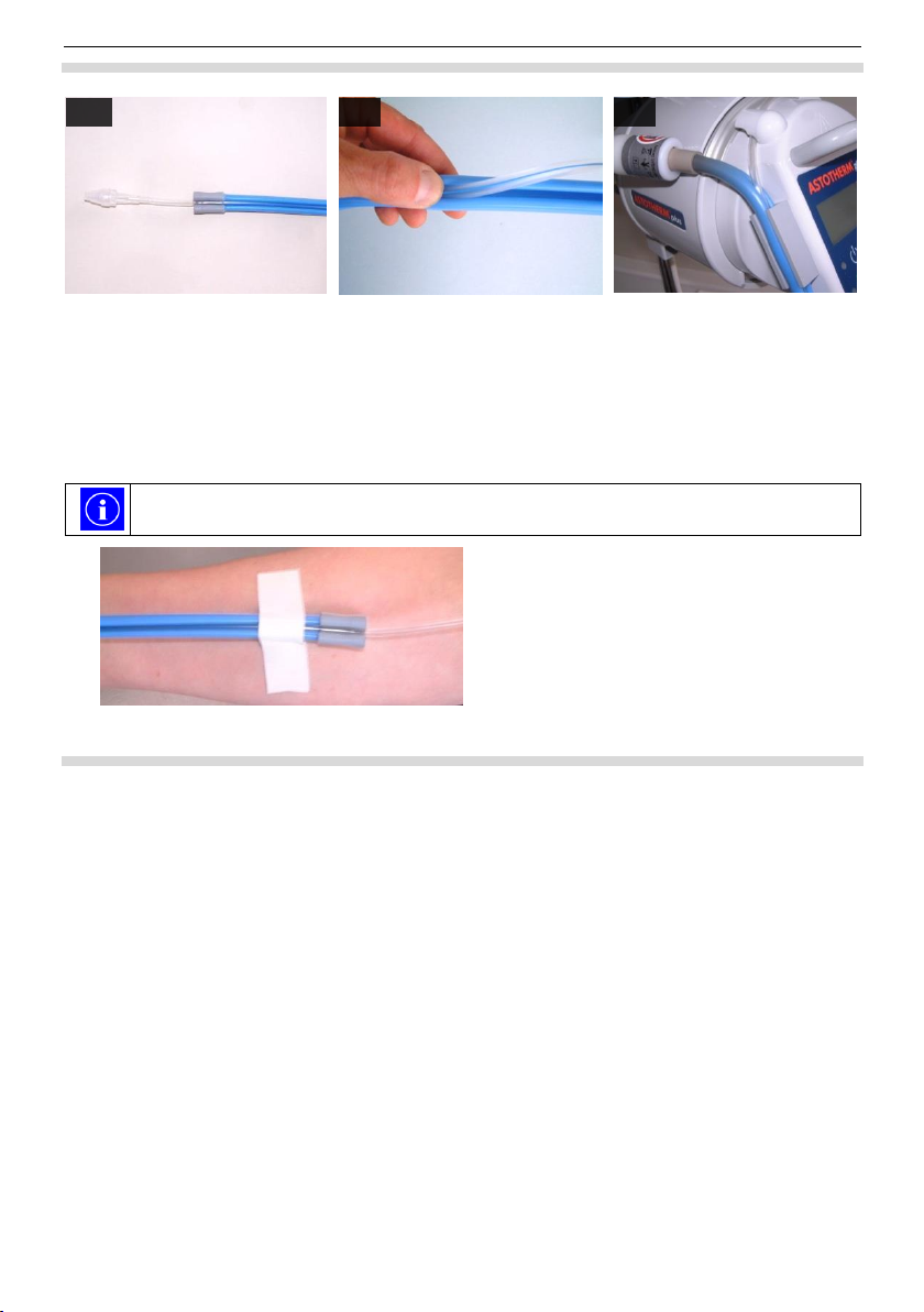
Fig. 10: The use of ASTOLINE
To facilitate insertion of the infusion extension into ASTOLINE,
ASTOLINE can be dusted with usual in trade powder or talcum powder.
Fig. 11: Fixing of ASTOLINE
10-A
10-B
10-C
Additionally for „S“ models:
5. Starting from the patient side, place the end of the infusion extension with
3 to 5 cm overlap into ASTOLINE (fig. 10-A) and insert it with the thumb into
the groove of ASTOLINE (fig. 10-B).
6. Clip ASTOLINE together with the inserted infusion extension into the bracket
(fig. 10-C).
7. Check the correct position of the infusion extension:
a. Infusion extension is fully in the groove
b. Infusion extension „skips“ no circulation
c. Infusion extension is not kinked or twisted in itself
8. Connect the infusion extension with infusion set of the liquid container.
9. Prime the infusion system: allow fluid to flow until no air is observed in the
infusion lines and the lines are completely filled with fluid.
10. Place the heat protection sleeve (optional) around the heat exchanger, align
the grips upwards and let the latches snap into place by squeezing.
11. Connect the patient side end of the infusion extension to the patient cannula
and ensure a good fixation (e.g. with tape), especially when ASTOLINE is
used (fig. 11).
36
Page 37
9 Getting started
ASTOTHERM PLUS Instructions for Use
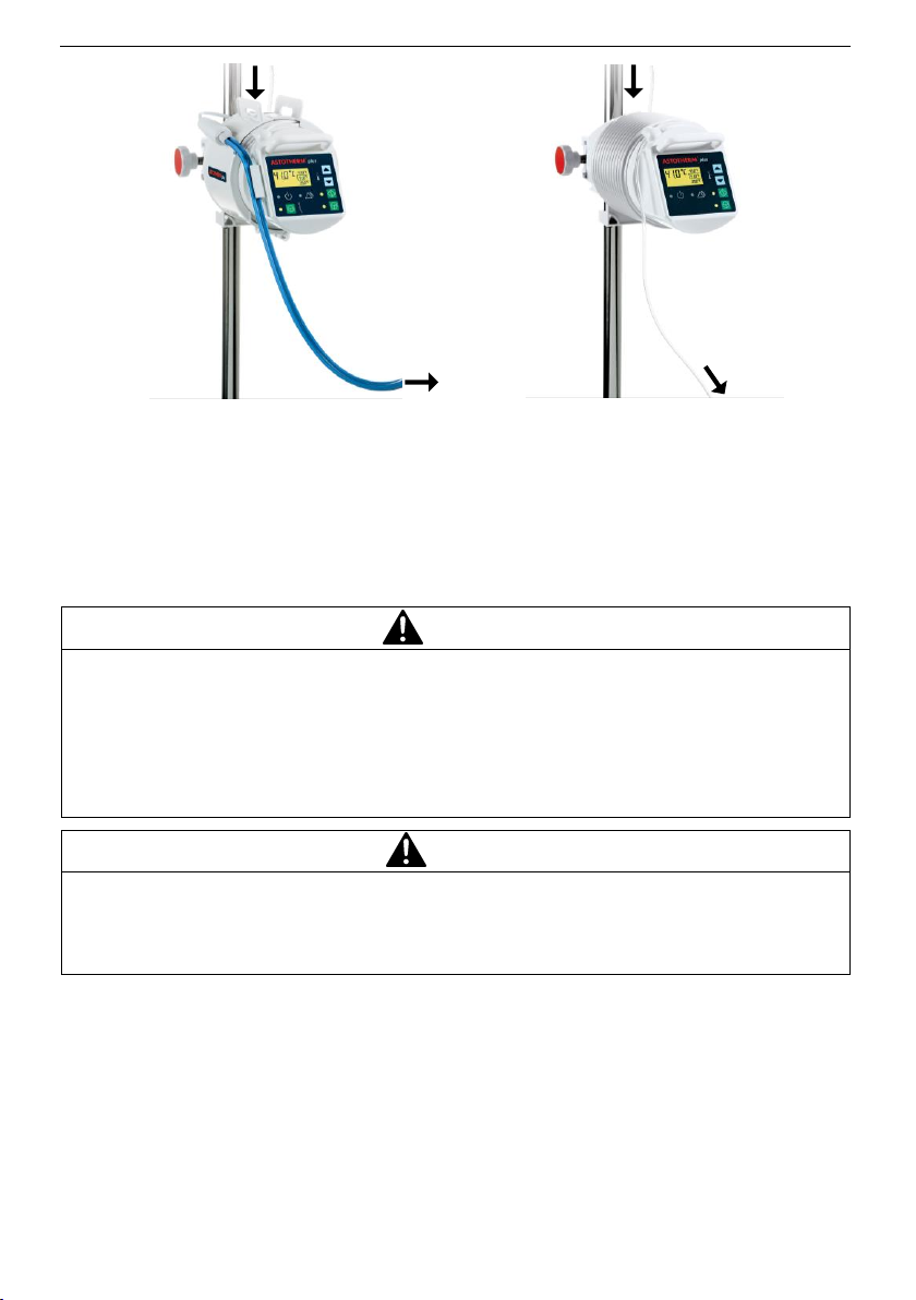
Fig. 12: ASTOTHERM PLUS prepared with
ASTOLINE and heat protection sleeve
Fig. 13: ASTOTHERM PLUS prepared
(without ASTOLINE and without heat
protection sleeve)
WARNING
Risk of overheating!
ASTOLINE („S“-models only) must hang freely while in use. Do not kink,
cover (not even partially), clamp (for example, with a surgical clamp) or roll
ASTOLINE.
Do not place ASTOLINE under or directly beside the patient. Heat build-up
can occur and/or the infusion extension can be squeezed off.
CAUTION
Risk of needle dislodgement!
The weight of ASTOLINE („S“-models only) pulls on the patient’s infusion line.
Carefully secure the patient’s access against pulling. Attach the ASTOLINE by
suitable methods (e.g. tape, plaster or Velcro®).
from the liquid container
to the patient
to the patient
from the liquid container
The infusion extension is now free hanging with ASTOLINE (fig. 12) or without
ASTOLINE (fig.13) between the patient and ASTOTHERM PLUS and the
treatment can be started.
37
Page 38
ASTOTHERM PLUS Instructions for Use
9 Getting started
To disconnect ASTOTHERM PLUS from the mains, it is necessary to
completely pull out the plug.
ASTOLINE does not have to be disconnected from its socket after use.
When not in use, ASTOLINE can be hung around the back of the
device.
NOTICE
If ASTOLINE is disconnected from ASTOTHERM PLUS, the appliance socket
should be covered with the protective cap. This prevents the contacts to
become polluted.
To avoid damaging during storage, place ASTOLINE loosely around the
warmer and do not kink or clamp it. Use narrow plaster strips or other narrow,
soft fixation methods (for example cannula fixation, tube holder or Velcro®) to
fix ASTOLINE.
9.3 After use
1. Discontinue infusion.
2. Press the “Standby” button for one second to switch off ASTOTHERM
PLUS and ASTOLINE („S“ models only).
All indicators turn off, the LED “Standby” turns on blue.
3. Disconnect the infusion extension from the cannula.
Only for „S“ models:
4. Pull the infusion line out of the ASTOLINE heating profile.
5. Detach the heat protection sleeve (optional).
6. Wrap the infusion extension out from the circumferential groove of the heat
exchanger.
7. Clean and disinfect ASTOTHERM PLUS and ASTOLINE after each treatment
and if required.
38
Page 39
9 Getting started
ASTOTHERM PLUS Instructions for Use
NOTICE
To avoid damage to the warmer and ASTOLINE:
- Do not immerse the warmer or ASTOLINE in liquid.
- Do not disinfect the warmer with these methods:
steam (autoclave)
hot air
thermo-chemical cleaning solutions.
- Refer to the specific instructions for use of the disinfectants.
CAUTION
Risk of injury!
Damage to ASTOLINE can cause overheating, therefore follow the instructions
below:
Only disinfect ASTOLINE with alcohol-based agents or an approved
disinfectant.
Do not use solutions containing hypochlorite (bleach) for disinfecting
ASTOLINE.
Do not kink or pull excessively ASTOLINE.
Do not use any clamps or sharp instruments on ASTOLINE as damage to
ASTOLINE or the infusion line inside may result.
Use narrow plaster strips or other narrow, soft fixation methods (for example
cannula fixation, tube holder or Velcro®) to fix ASTOLINE.
Do not use cleaning and disinfection procedures which differ from the
procedure described.
9.4 Cleaning and disinfecting
ASTOTHERM PLUS
Clean and wipe-disinfect ASTOTHERM PLUS in accordance with the procedure
below:
1. Disconnect the mains plug from the socket.
2. Clean all surfaces with a soft cloth/cotton swab and mild soap-and-water
solution.
3. Disinfect ASTOTHERM PLUS with either:
An approved disinfectant
An alcohol-based disinfectant with a low content of aldehydes (< 0.2%)
A mild bleach solution (max. 0.25 % hypochlorite)
39
Page 40
ASTOTHERM PLUS Instructions for Use
9 Getting started
To facilitate insertion of the infusion extension, ASTOLINE can be
dusted with usual in trade powder or talcum powder.
Meliseptol®
Clinell Alcohol Wipes
Biguamed® Perfekt N
Incidin® Plus
Mikrozid® Liquid
HyPro medical 3% H2O2
Bacillol® Plus
Aniosurf
Mikrobac® forte
Oxivir Tb
ClearSurf®
Diosol 3% H2O2 PURE
Clinell Universal Sanitising Wipes
Virox5 RTU
ASTOLINE
Clean and wipe-disinfect ASTOLINE in accordance with the procedure below:
1. Clean all surfaces of the heating profile including the groove with a soft cloth/
cotton swab and a mild soap-and-water solution or with water only.
2. Disinfect the ASTOLINE only with approved disinfectants or with disinfectants
based on alcohol with a low content of aldehyds (< 0.2 %).
Do not disinfect ASTOLINE with disinfectants containing hypochlorite
(bleach).
In doing so follow the contact time of the disinfectant given in the specific
instructions for use of the disinfectant! After this time dry ASTOLINE.
3. Residuals of disinfectants cause a sticky surface, it is strongly recommended
to rinse with water after about 5 disinfections or once a week.
List of approved disinfectants*:
*In the United States please use only disinfectants which are registered by EPA
(U.S. Environmental Protection Agency) or cleared by FDA (U.S. Food and Drug Administration).
40
Page 41

10 Alarms and troubleshooting
ASTOTHERM PLUS Instructions for Use
Alarm signal
Characteristics
visible
yellow LED lights constantently
audible
Sound pulse, all 17 sec.
10 Alarms and troubleshooting
In the event of device failure, two independent monitoring systems ensure the
safety against overheating. Except for the low temperature alarm, all alarms
switch off immediately the heating function. Thus, the overheating of the heated
liquid is surely prevented.
ASTOTHERM PLUS does not require continuous supervision by the operator, but
it must be checked at regular intervals (depending on the condition of the patient
status). Then the intended operator’s position is directly in front of the control
panel.
In case of failure of the equipment, possible injury to the patient is delayed and
the operator has sufficient time to provide alternative warming methods.
According to IEC/EN 60601-1-8 the alarms are defined as “Low Priority Alarms”.
The alarms are only triggered by technical alarm conditions (equipment faults).
The alarm signal is given visually and acoustically.
41
Page 42
ASTOTHERM PLUS Instructions for Use
10 Alarms and troubleshooting
10.1 Low temperature alarm
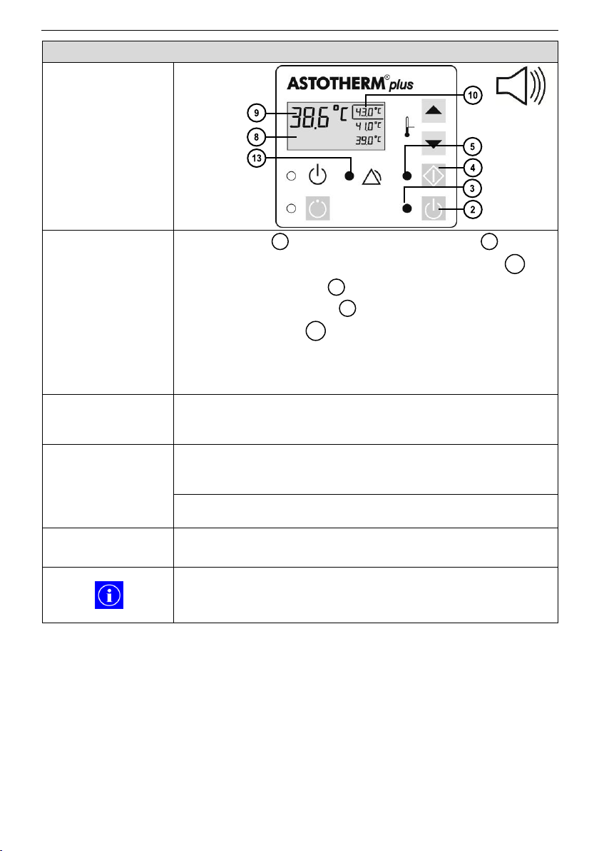
Control panel
Device response
The display shows an actual temperature , which
is more than 4°C below the setpoint temperature .
The green “On” LED lights.
The green “Start” LED lights.
The “Alarm” LED lights yellow.
The acoustic alarm signal is activated with a 2 minute
delay.
The heating element is not switched off.
Alarm condition
The current temperature of the heat exchanger is more
than 4°C below the setpoint temperature during Heating
Mode.
Possible reason(s)
►Required
action(s)
Inlet temperature of the liquid is too low and the flow rate is
too high.
►Reduce flow rate.
Warmer is defective.
►Return ASTOTHERM PLUS to local sales office.
Possible actions to
clear
None, the alarm is automatically disabled if the alarm
condition is eliminated.
During warm up phase, as long as the actual temperature
is 4°C below the selected setpoint temperature, low
temperature alarm is displayed (visual alarm signal only).
8
9
10
3
5
13
42
Page 43
10 Alarms and troubleshooting
ASTOTHERM PLUS Instructions for Use
10.2 Overheating alarm
Control panel
Device response
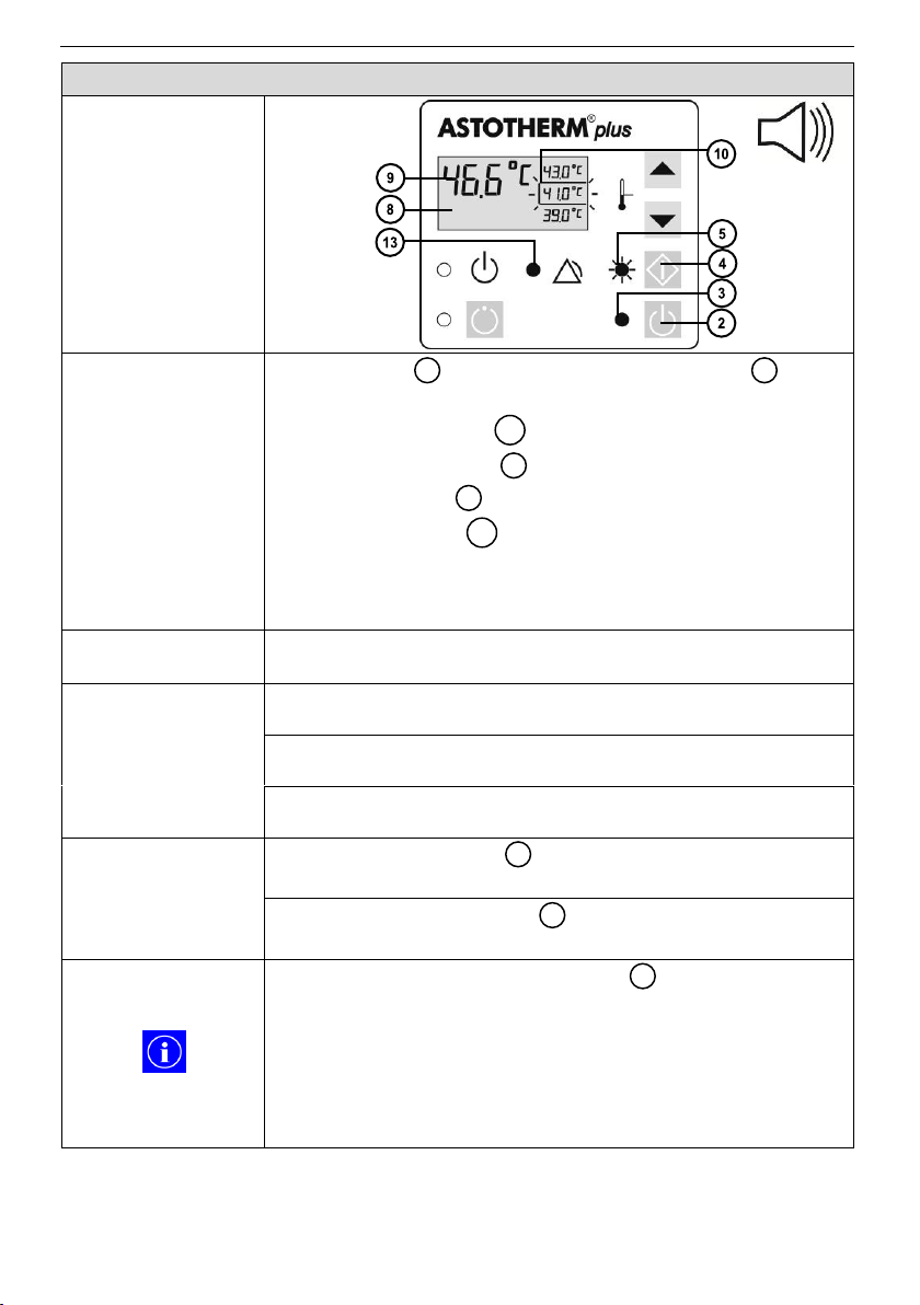
The display shows the current temperature ,
which drops slowly after the alarm was activated.
The selection frame flashes.
The green “On” LED lights.
The “Start” LED flashes green.
The “Alarm” LED lights yellow.
The acoustic alarm signal sounds every 17 seconds.
The heating element is switched off.
ASTOLINE („S“-models only) is switched off.
Alarm condition
The temperature of the heat exchanger rises to the alarm
limit of 45.5C 1.0C.
Possible reason(s)
►Required
action(s)
Effect of external heat source, such as sunlight or radiator.
►Eliminate the heat source and/or select cooler location.
Ambient temperature too high.
►Eliminate heat source and/or select cooler location.
Warmer is defective.
►Return ASTOTHERM PLUS to local sales office.
Possible actions to
clear
Press the “Start” button to switch the device back to
Heating Mode (after cooling down).
Press the “Standby” button to switch the device to
Standby Mode.
As long as the actual temperature is above the alarm
limit, the warmer cannot be switched to the Heating
Mode.
In order to prevent potential overheating due to a
possible failure of the temperature control system, the
ASTOTHERM PLUS possesses two independent
excessive temperature cut offs.
8
9
10
3
5
13
4
2
43
Page 44
ASTOTHERM PLUS Instructions for Use
10 Alarms and troubleshooting
10.3 Cable break alarm
Control panel
Device response
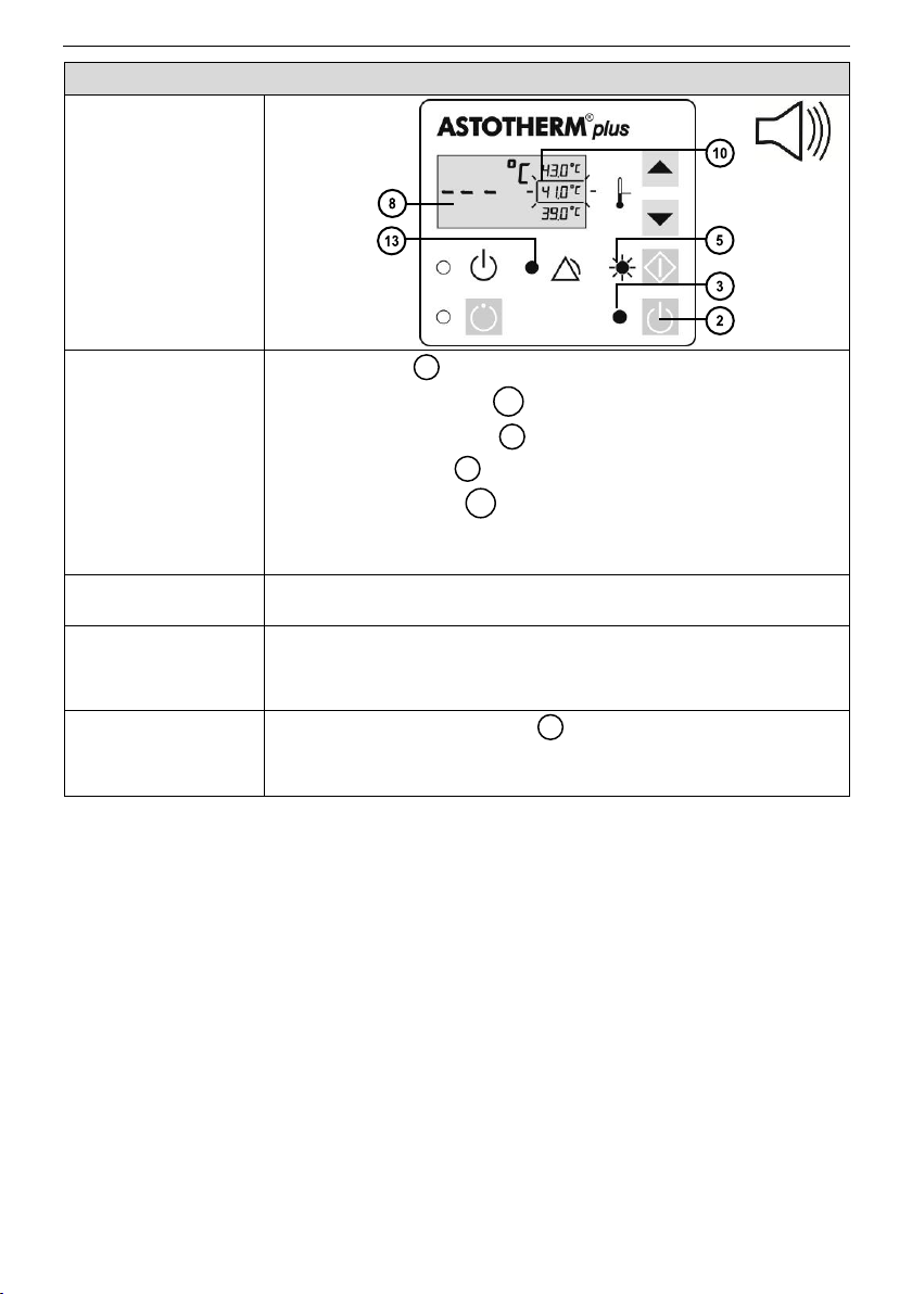
The display shows „- - -„.
The selection frame flashes.
The green “On” LED lights.
The “Start” LED flashes green.
The “Alarm” LED lights yellow.
The acoustic alarm signal sounds every 17 seconds.
The heating element is switched off.
Alarm condition
A defect of the cable break detection or a temperature
sensor break has been detected.
Possible reason(s)
►Required
action(s)
Warmer is defective.
►Return ASTOTHERM PLUS to local sales office.
Possible actions to
clear
Press the “Standby” button to switch the device to
Standby Mode.
8
10
3
5
13
2
44
Page 45
10 Alarms and troubleshooting
ASTOTHERM PLUS Instructions for Use
10.4 ASTOLINE alarm (“S” models only)
Control panel
Device response
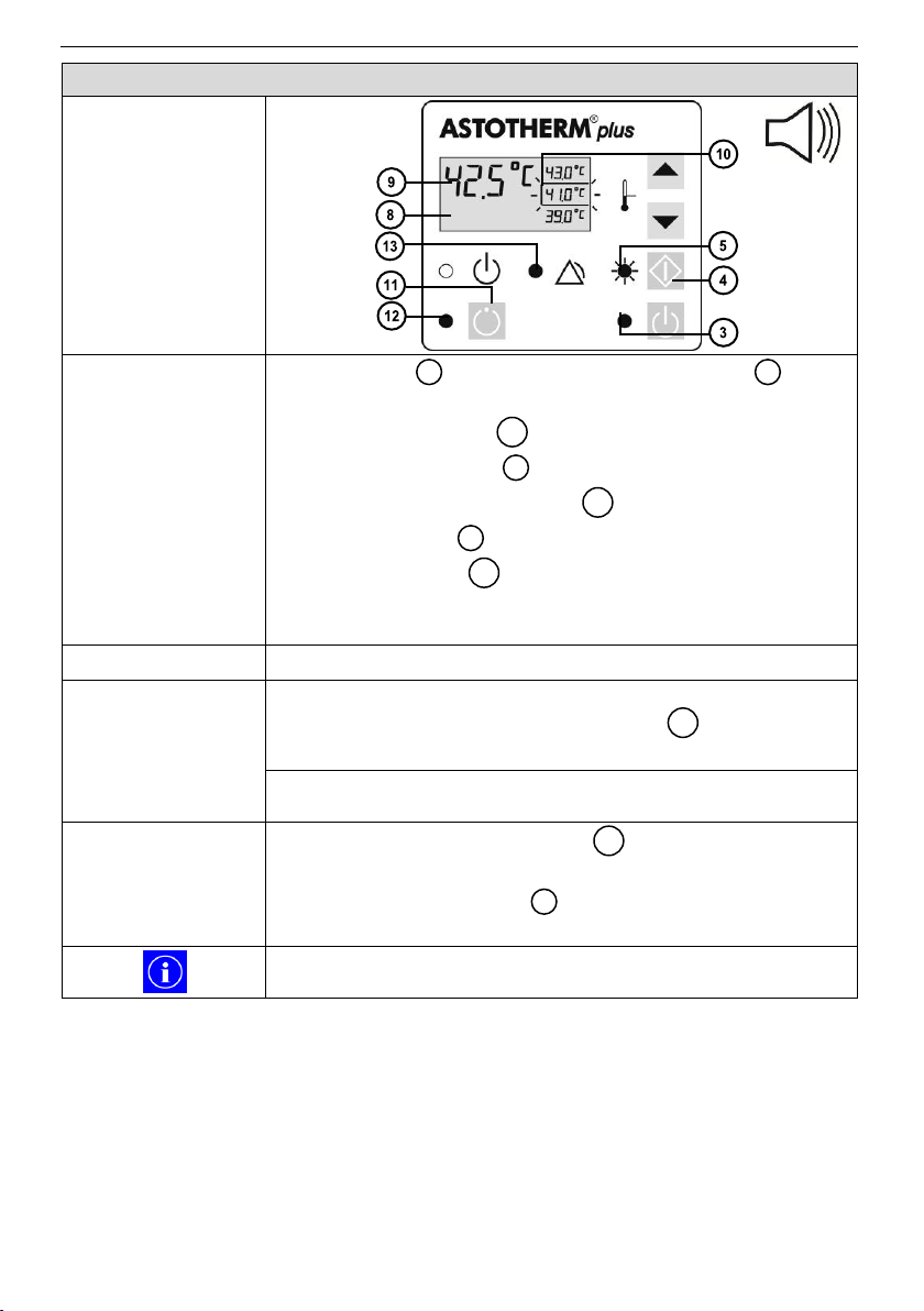
The display shows the current temperature ,
which drops slowly after the alarm was activated.
The selection frame flashes.
The green “On” LED lights.
The green “ASTOLINE” LED lights.
The “Start” LED flashes green.
The “Alarm” LED lights yellow.
The acoustic alarm signal sounds every 17 seconds.
The heating element is switched off.
Alarm condition
The power supply of ASTOLINE is open or shorted.
Possible reason(s)
►Required
action(s)
ASTOLINE is not connected and it was tried to switch on
ASTOLINE with the “ASTOLINE” button .
►Connect ASTOLINE and repeat procedure.
ASTOLINE is defective.
► Return ASTOLINE to local sales office.
Possible actions to
clear
1. Press the “ASTOLINE” button to switch off
ASTOLINE.
2. Press the “Start” button to switch the device to
Heating Mode.
In the case of a defective ASTOLINE, ASTOTHERM PLUS
can be used with deactivated ASTOLINE.
8
9
10
3
12 5 13
11
11
4
45
Page 46
ASTOTHERM PLUS Instructions for Use
10 Alarms and troubleshooting
10.5 Processor alarm
Control panel
Device response
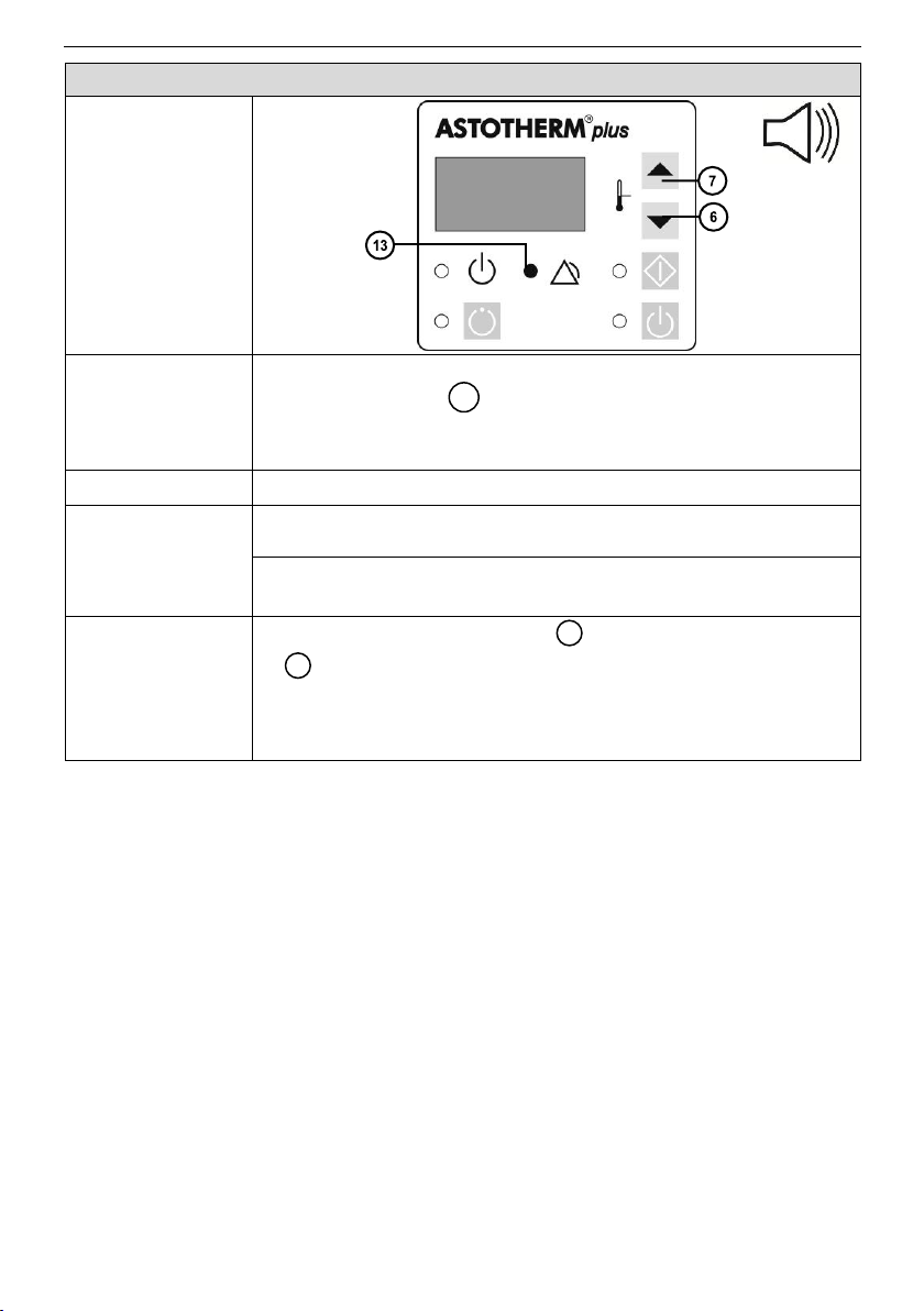
Even when you plug in the power cord ….
the “Alarm” LED lights yellow.
the acoustic alarm signal sounds every 17 seconds.
none of the buttons can cause a device reaction.
Alarm condition
Program fault.
Possible
reason(s)
►Required
action(s)
Temporary program fault.
►Alarm reset (see below).
Permanent program fault caused by defect data file.
►Return ASTOTHERM PLUS to local sales office.
Possible actions
to clear
1. Press the “Increase” button and the “Decrease” button
at the same time until the device switches to Standby
Mode.
2. Unplug the power cord and wait one minute.
3. Plug in again the power cord.
13
7
6
46
Page 47
10 Alarms and troubleshooting
ASTOTHERM PLUS Instructions for Use
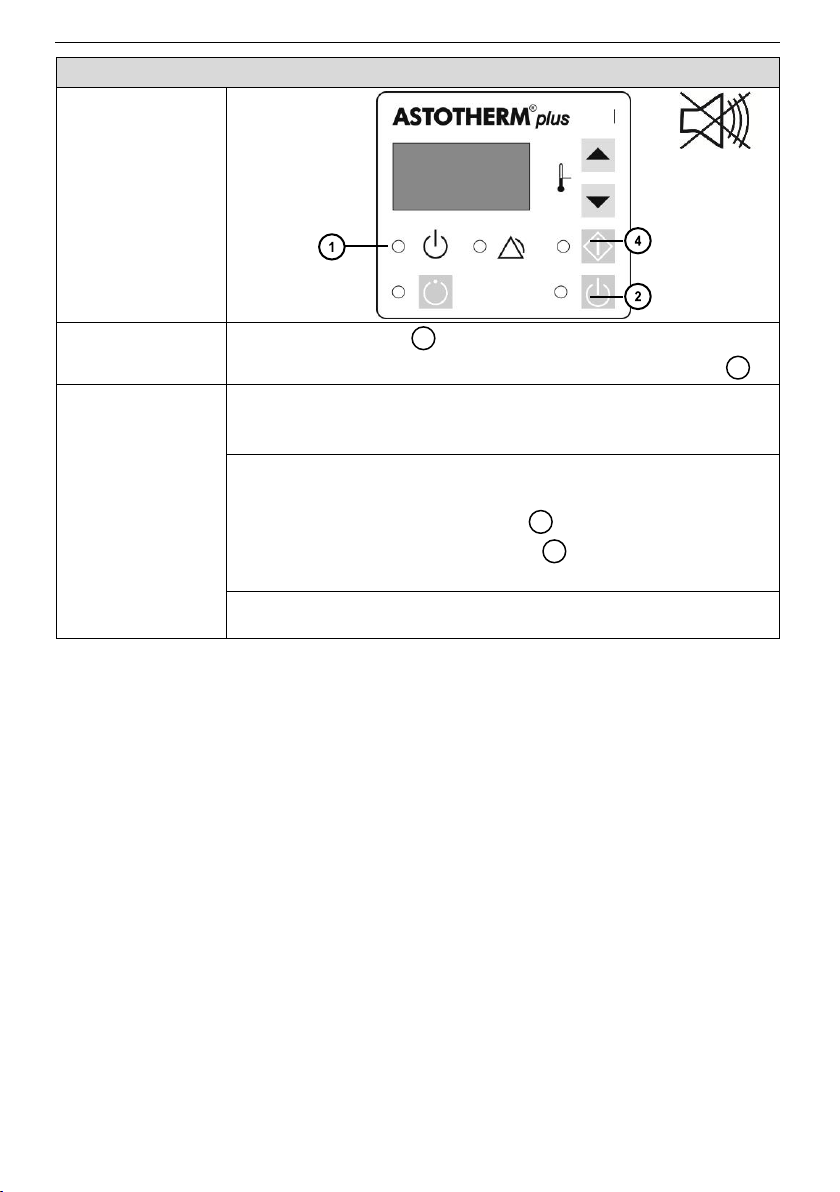
10.6 Standby mode - failure
Control panel
Device response
The “Standby” LED is off and the device cannot be
switched to On Mode by pressing the “Standby” button .
Possible
reason(s)
►Required
action(s)
Power supply problem or no power.
►Check plugs and fuses compare mains voltage with rating
plate.
Warmer not plugged in.
►
1. Plug the warmer into functioning socket.
2. Press the “Standby” button .
3. Press then the “Start” button to switch the device
to Heating Mode.
Warmer is defective.
►Return ASTOTHERM PLUS to local sales office.
1 2 2
4
47
Page 48
ASTOTHERM PLUS Instructions for Use
11 Brief overview of operating states and alarms
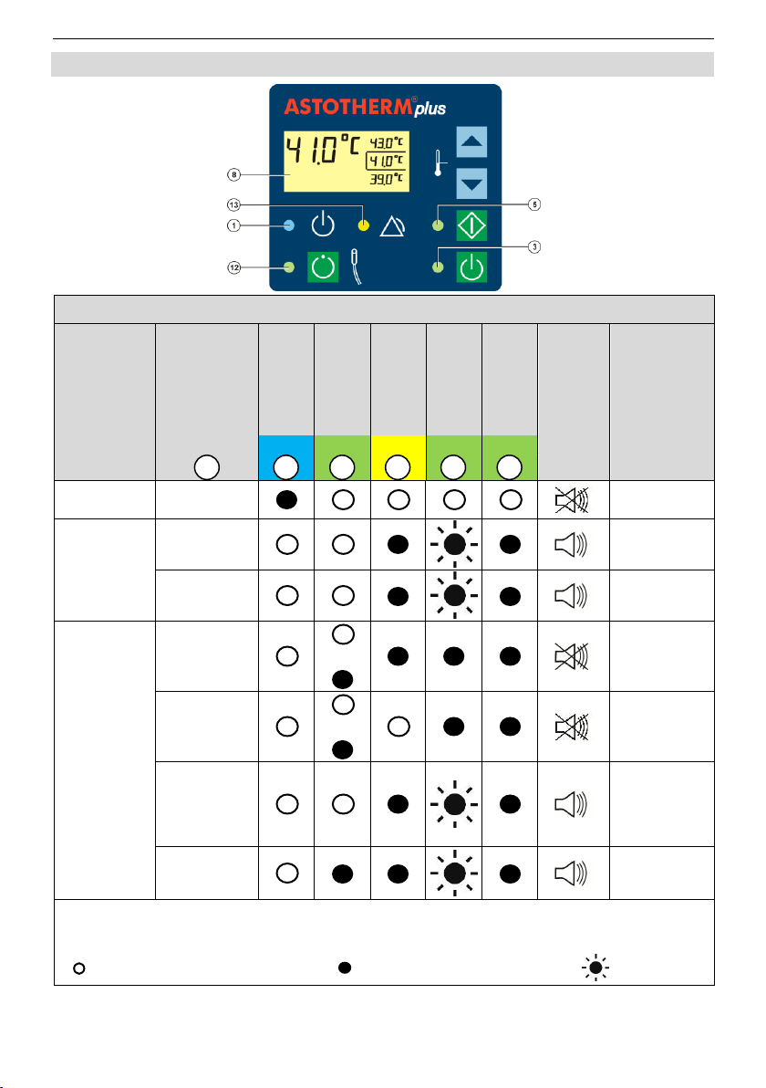
11.1 Overview of operating states
Operating
state
Display
“Standby“
LED
“ASTOLINE“
LED
“Alarm“ LED
“Start“ LED
“On“ LED
Acoustic alarm
signal
Possible
reason(s)
blue green
yellow
green
green
Standby Mode
OFF
-
On Mode
---
T
Act
≤ 15°C
or
T
Act
≥ 50°C
T
Act
-
Heating Mode
---
or
T
Act
≤ 15°C
T
Act
or
-
T
Act
„Start” button
has been pressed too short.
Otherwise
device defect.
T
Act
Defective
ASTOLINE or
not connected
T
act
= Actual Temperature (current temperature of heat exchanger)
T
set
= Setpoint Temperature (selected temperature, marked by a frame)
=
LED is off
=
LED lights
=
LED flashes
8 1 12
13 5 3
11 Brief overview of operating states and alarms
48
Page 49
11 Brief overview of operating states and alarms
ASTOTHERM PLUS Instructions for Use
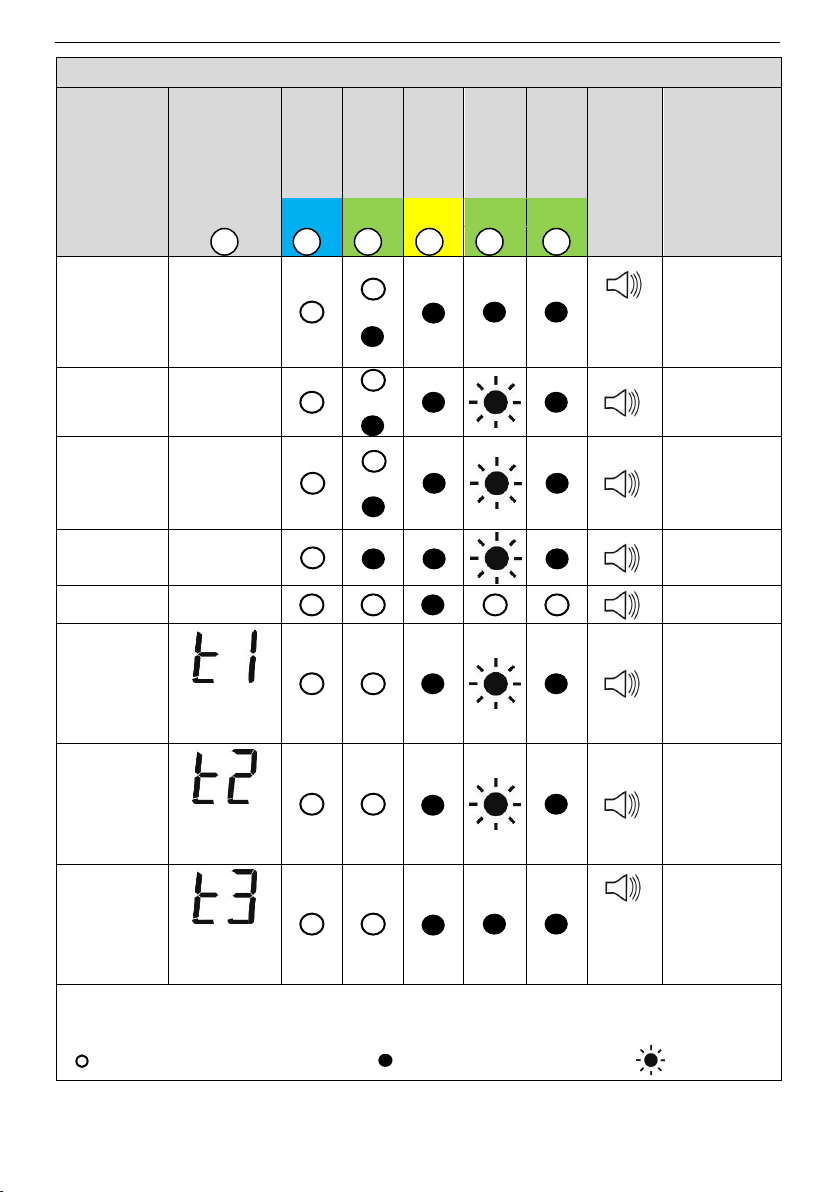
11.2 Overview of alarms
Alarm
Display
“Standby“
LED
“ASTOLINE“
LED
“Alarm“ LED
“Start“ LED
“On“ LED
Acoustic alarm
signal
Possible
reason(s)
blue
green
yellow
green
green
Low
Temperature
Alarm
T
act
or
sounds
every 2
min.
Low temperature
(T
act
≤ T
set
- 4°C)
because of cold
liquid/high flow
rate or device
defective
Excessive
Temperature
Alarm
T
act
or
T
act
> 45.5°C
± 1°C
Cable Break
Alarm
---
or
Temperature
sensor(s) or
associated
circuit(s)
interrupted
ASTOLINE
Alarm
T
act
Defective
ASTOLINE or
not connected
Processor
Alarm
OFF
Program failure
Manual
Excessive
Temperature
Alarm
Test 1
alternating
with T
act
„Start” button
has been
pressed for
longer than 3
seconds
Manual
Excessive
Temperature
Alarm
Test 2
alternating
with T
act
„Increase” button
has been
pressed for
longer than 3
seconds
Manual Low
Temperature
Alarm
Test 3
Alternating
with T
act
after
cooling to
T
act
≤
T
set
– 4°C
„Decrease”
button has been
pressed for
longer than 3
seconds
T
act
= Actual Temperature (current temperature of heat exchanger)
T
set
= Setpoint Temperature (selected temperature, marked by a frame)
=
LED is off
=
LED lights
=
LED flashes
8 1 12
13 5 3
49
Page 50
ASTOTHERM PLUS Instructions for Use
12 Maintenance
No service or maintenance shall be carried out while in use with a
patient.
WARNING
Risk of injury!
The service personnel must be appropriately trained and qualified.
The ASTOTHERM PLUS does not contain any parts the user can repair.
Therefore, do not attempt to repair the ASTOTHERM PLUS yourself.
Contact your local sales point.
Any repairs (such as, but not limited to, changing the power supply cord) to
the equipment may only be carried out by persons authorised and qualified
by the manufacturer.
Modifications to the device are not permitted.
12 Maintenance
ASTOTHERM PLUS does not require preventive maintenance (e.g. replacement
of liquids or components). Recurrent tests shall be performed according to
chapter 12.1.
The accessories specified in chapter 15 Ordering information, accessories
and consumables may be replaced without restriction by the operating or
maintenance personnel.
On request, STIHLER ELECTRONIC GmbH will provide service instructions that
will allow properly trained and qualified persons to repair the parts of the
equipment that the manufacturer has designated as repairable.
Provision of technical documents and/or spare parts is not an authorisation from
the manufacturer to open or repair the equipment.
12.1 Recurrent tests
12.1.1 Warmer ASTOTHERM PLUS (ASTOLINE see 12.1.2)
A recurrent test must be carried out on the ASTOTHERM PLUS warmer at least
every 24 months to ensure the safe operation of the warmer.
Please ensure that all the applicable national directives (e.g. IEC/EN 62353) for
checking the safety of medical equipment are observed additionally and that the
test equipment is calibrated.
Necessary test equipment:
Standard medical electrical safety tester
Digital clinical thermometer (max. diameter of probe tip 3.5 mm and
accuracy ± 0.1°C)
50
Page 51

12 Maintenance
ASTOTHERM PLUS Instructions for Use
Test 1
Visual inspection
Required
Actions
Check the following items:
Complete and legible labeling.
No damage to the housing.
Control panel in good condition. (Since the front foil prevents
fluid from entering the unit, it is important that its full surface
adheres securely to the housing.)
No defects in the power supply cord and mains connector
insulation, with clean and non-corroded contacts.
Test 2
Protective earth resistance
Required
Actions
Measure the resistance between the earth pin on the power plug
and the connector for potential equalization, located on the rear
side of the housing.
For detailed information performing this test see chapter 12.2
Set up for electrical tests.
Result
The test is successful when the limits are met in accordance with
the test protocol.
Test 3
Insulation resistance
Required
Actions
Measure the resistance of the insulation between the live parts
and the parts which are connected to earth.
For detailed information performing this test see chapter 12.2
Set up for electrical tests.
Result
The test is successful when the limits are met in accordance with
the test protocol.
The following sections describe how the tests are to be performed. The attached
test protocol (see chapter 12.3 Test protocol) can be used.
51
Page 52

ASTOTHERM PLUS Instructions for Use
12 Maintenance
Test 4.1
Optional to test 4.2
Equipment leakage current (alternative method)
Required
Actions
Measure the current flowing from protective earthed conductor
to the two (shorted) power supply connections.
For detailed information performing this test see chapter 12.2
Set up for electrical tests.
Result
The test is successful when the limits are met in accordance with
the test protocol.
Test 4.2
Optional to test 4.1
Earth leakage current (direct method)
Required
Actions
Measure the maximum earth leakage current (PE open)*.
Measure all combinations of line polarity with neutral open
(single fault condition) and closed (normal condition).
For detailed information performing this test see chapter 12.2
Set up for electrical tests.
Result
The test is successful when the limits are met in accordance with
the test protocol.
or alternatively:
*is usually done automatically by the safety tester
52
Page 53
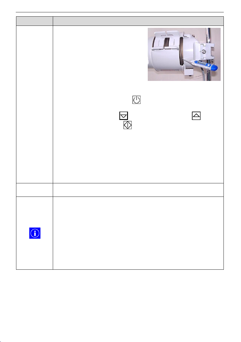
12 Maintenance
ASTOTHERM PLUS Instructions for Use
Test 5
Temperature control and display
Required
Actions
1. Insert the clinical thermometer
into the rear measuring bore on
the side of the heat exchanger.
2. Plug the mains plug into a socket.
3. Press the “Standby” button (On Mode).
4. Select a temperature of maximum 41°C (if necessary press
the “Decrease” button or the „Increase” button .
5. Press the “Start” button for at least one second (Heating
Mode).
6. Wait about 5 minutes until the actual temperature is equal to
the setpoint temperature.
7. Start the measurement on the clinical thermometer and
measure the actual temperature of the heat exchanger.
8. Compare the measured temperature with the displayed
temperature and the selected setpoint temperature of the
Warmer.
Result
The test is successful when the limits are met in accordance with
the test protocol (chapter 12.3 Test protocol)
This test is used to check the essential performance.
Absolutely avoid during this measurement influences from the
environment (drafts, heat radiation of other heat sources, etc).
Use if available the heat protection sleeve (slightly rotated so
that the measuring bore is freely accessible).
Clinical thermometers are designed as „immersion sensors“. In
order to achieve a sufficiently accurate measurement result,
the thermometer must be immersed deep enough (depending
on manufacturer and type). Because here only the metal tip of
the thermometer is used, usually the measured temperature is
slightly lower than the real temperature.
Fig. 14: Temperature measurement
53
Page 54
ASTOTHERM PLUS Instructions for Use
12 Maintenance
Test 6
Manual excessive temperature cut off 1
Required
Actions
1. Operate the Warmer with the middle setpoint temperature.
2. Hold down the “Start” button at least for 3 seconds, to
start the test.
Result
The test is successful, when:
The display alternately indicates t1 and the actual temperature
and after a short time
- the “Start” LED flashes green,
- the “Alarm” LED lights yellow,
- the acoustic alarm signal sounds.
The test is not successful if any of the following conditions
occurs:
The display does not indicate t1.
The “Start” LED does not flash.
The “Alarm” LED does not light.
The acoustic alarm does not beep.
For the continuation of the tests, press the “Start” button to
switch the Warmer back to the Heating Mode.
Test 7
Manual excessive temperature cut off 2
Required
Actions
1. Operate the Warmer with the highest setpoint temperature.
2. Hold down the “Increase” button at least for 3 seconds, to
start the test.
Result
The test is successful, when:
The display alternately indicates t2 and the actual temperature
and after a short time
- the “Start” LED flashes green,
- the “Alarm” LED lights yellow,
- the acoustic alarm signal sounds.
The test is not successful if any of the following conditions
occurs:
The display does not indicate t2.
The “Start” LED does not flash.
The “Alarm” LED does not light.
The acoustic alarm does not beep.
For the continuation of the tests, press the “Start” button to
switch the Warmer back to the Heating Mode.
54
Page 55
12 Maintenance
ASTOTHERM PLUS Instructions for Use
Test 8
Manual low temperature alarm
Required
Actions
1. Operate the Warmer with the lowest setpoint temperature.
2. Hold down the “Decrease” button at least for 3 seconds, to
start the test.
Result
The test is successful, when:
The display alternately indicates t3 and the actual
temperature.
The actual temperature slowly decreases, and after cooling to
T
Act
= T
Set
– 4°C
- the “Alarm” LED flashes yellow and
- after another 2 minutes, the acoustic alarm signal sounds.
The test is not successful if any of the following conditions
occurs:
The display does not indicate t3.
The “Alarm” LED does not light after cooling.
The acoustic alarm signal does not beep after another 2
minutes waiting time.
Without heat protection sleeve the Warmer cools down faster
in this test.
The cooling time depends in the initial temperature and the
ambient temperature.
To exit the test, press the “Standby” button to switch the
Warmer to the Standby Mode.
55
Page 56
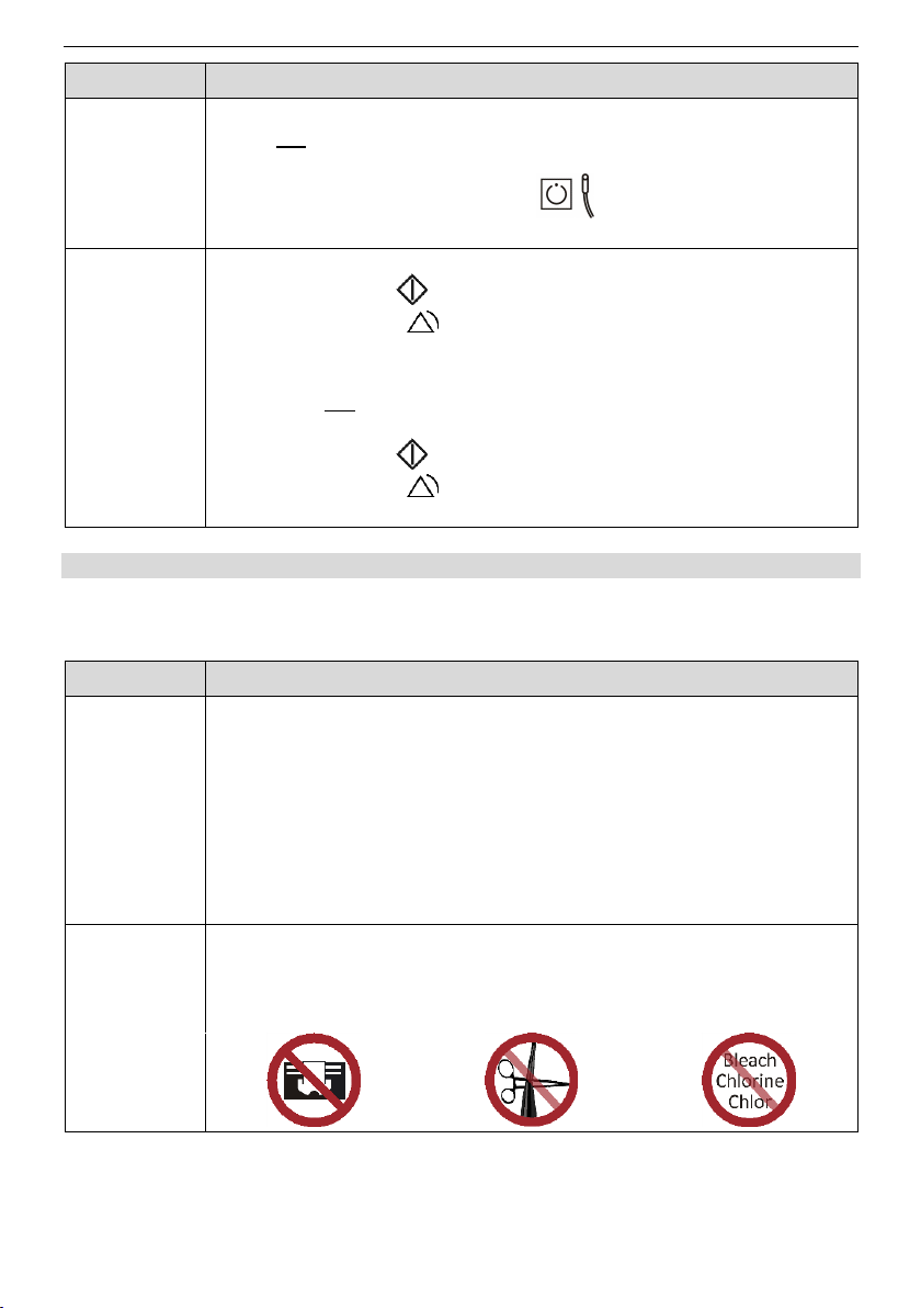
ASTOTHERM PLUS Instructions for Use
12 Maintenance
Test 9
Manual ASTOLINE cut off („S“ models only)
Required
Actions
1. Operate the Warmer with any setpoint temperature.
2. Do not connect ASTOLINE to the designated appliance
socket or disconnect the plug of ASTOLINE.
3. Press the „ASTOLINE” button to switch the Warmer to
ASTOLINE On Mode.
Result
The test is successful, when:
The “Start” LED flashes green.
The “Alarm” LED flashes yellow.
The acoustic alarm signal sounds.
The test is not successful if any of the following conditions
occurs:
The “Start” LED does not flash.
The “Alarm” LED does not flash.
The acoustic alarm signal does not beep.
Test 10
Visual inspection
Required
actions
1. Clean ASTOLINE with an alcohol-based agent.
2. Dust ASTOLINE (groove and outer side) with talcum powder.
3. Pull the entire silicone jacket from ASTOLINE trough the hand
and pay attention to:
- unusual discolorations in the groove or on the outer
surface of the profile
- damages, scratches, cuts or open areas in the silicone
profile
4. Check marking and the safety signs.
Result
The test is successful, when
No discolorations are visible
No damages are present
The safety signs are complete and legible
12.1.2 Active insulation ASTOLINE
In order to ensure the safe operating condition, the recurrent test of ASTOLINE
must be carried out at least every 24 months.
56
Page 57
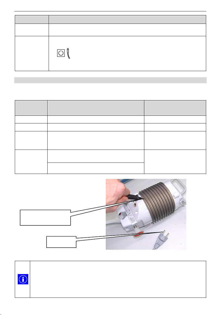
12 Maintenance
ASTOTHERM PLUS Instructions for Use
Test 11
Functional test
Required
actions
Operate ASTOLINE together with the warmer ASTOTHERM
PLUS.
Result
The test is successful, when
ASTOLINE can be switchen on with the “ASTOLINE” button
The “ASTOLINE” LED illuminates green
No alarm is indicated.
Test
Measurement (True RMS)
(see also IEC/EN 62353)
Use connection to
electrical safety analyzer
2
Protective earth resistance
Connection 1 and 2
3
Insulation resistance
Connection 1
4.1
optional to 4.2
Equipment leakage current
(alternative method)
Connection 1
(and possibly connection 2,
depending on the used safety
analyzer)
4.2
optional to 4.1
Earth leakage current N.C.
(direct method)
Connection 1
Earth leakage current S.F.C
(direct method, N open)
In order to achieve a sufficient accurate measurement result, during the
measurement of the protective earth resistance, good electrical contact
with the metal of the heat exchanger must be established.
On the top of the heat exchanger (backside) is a small bare spot to
make the contact with the probe. At this point the (insulating) anodic
coating of the heat exchanger is penetrated by the manufacturer’s test.
Connection 1:
Mains plug
Connection 2:
Probe to heat exchanger
(=touchable and conductive)
12.2 Set up for electrical tests
For measuring the protective earth resistance, the insulation resistance and the
equipment/earth leakage current, the following test set up can be used:
Abb. 15: Test set up for measuring
57
Page 58
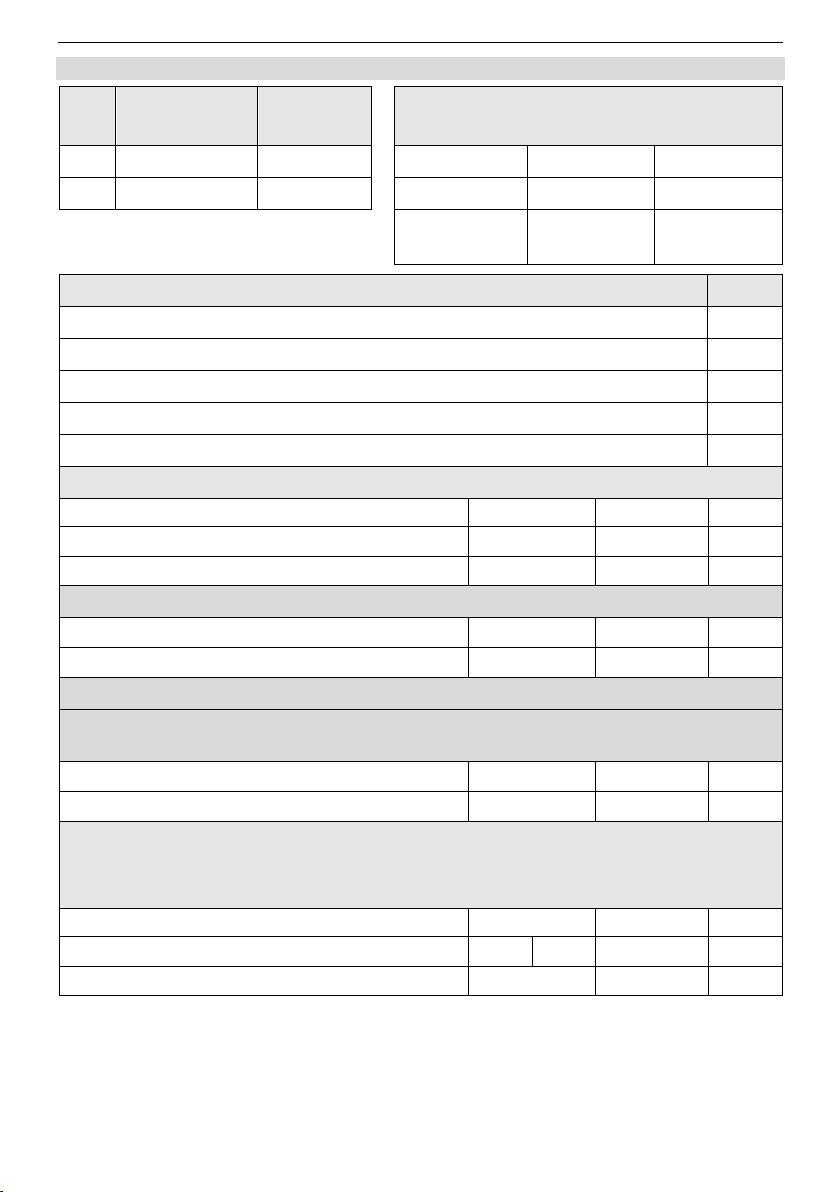
ASTOTHERM PLUS Instructions for Use
12 Maintenance
ASTOTHERM
PLUS
ASTOLINE
Test equipment
Type
Type
SN
SN
Date of
calibration
Test 1: Visual inspection
P/F
Labeling and markings on ASTOTHERM PLUS
Control panel (front foil)
Housing
Power supply cord
Attachment device
Test 2: Protective earth resistance
Value [Ω]
Max [Ω]
P/F/NA
Protective earth resistance
0.3
Resistance potential equilization (optional)
0.3
Test 3: Insulation resistance
Value [MΩ]
Min [MΩ]
P/F
Insulation resistance
100
Test 4: Leakage current test either to 4.1 or 4.2
4.1 Equipment leakage current (alternative method)
Alternative test for measurement the earth leakage current using the direct method (Test 4.2)
Value [mA]
Max [mA]
P/F
Equipment leakage current
1.0
4.2 Earth leakage current (direct method)
Alternative test for measurement the equipment leakage current using the alternative method
(Test 4.1)
PE (Protective ground) open. Measure all combinations of line polarity.
Value [mA]
Max [mA]
P/F
Earth leakage current N.C
0.5
Earth leakage current S.F.C (N open)
1.0
12.3 Test protocol
58
Page 59
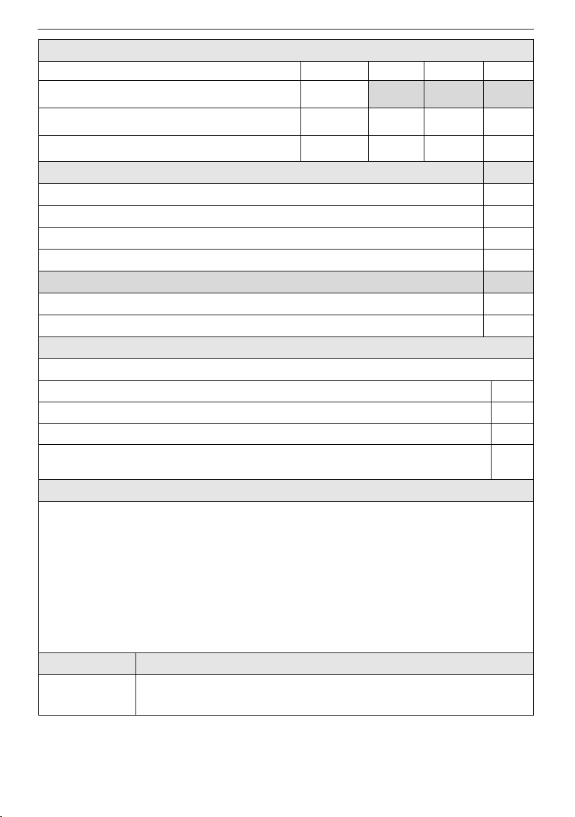
12 Maintenance
ASTOTHERM PLUS Instructions for Use
Test 5: Temperature control and display
Value [°C]
Min [°C]
Max [°C]
P/F
Selected setpoint temperature T
(max. 41°C)
Temperature measurement TT
(with clinical thermometer)
T – 0.5
T + 0.5
Actual temperature (displayed) TD
T – 0.3
T + 0.3
Manual tests
P/F/NA
Test 6: Manual excessive temperature cut off 1 (t1)
Test 7: Manual excessive temperature cut off 2 (t2)
Test 8: Manual low temperature alarm (t3)
Test 9: Manual ASTOLINE cut off
ASTOLINE
P/F/NA
Test 10: Visual inspection ASTOLINE
Test 11: Functional test
Overall assessment
Please mark where applicable
No safety or functional deficiencies were detected
No direct risk, deficiencies detected may be corrected on short term
Equipment shall be taken out of operation until deficiencies are corrected
Equipment does not comply – Modification / Exchange of components / Taking
out of service - is recommended
Comments
Date
Signature
59
Page 60
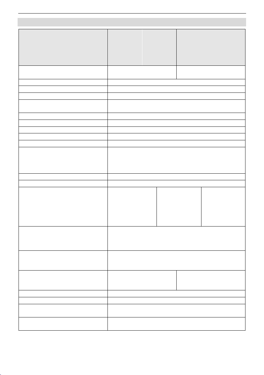
ASTOTHERM PLUS Instructions for Use
13 Technical data
ASTOTHERM PLUS
REF AP220..
AP220S..
AP260..
AP260S..
..AU
..CH
..CN
..DK
..EU
..UK
..NA
..JA
Electrical connection
230 - 240 VAC
50 – 60 Hz
100 - 115 VAC
50 – 60 Hz
Fuses primary
(F1 F2)
T4AH 250 V (5 x 20 mm)
Fuses secondary
(F3 F4)
T0630AL 250 V (TR5 type)
Power consumption
max. 450 W
Classification
(IEC/EN 60601-1)
Class I, Type B
applied part is defibrillation proof
Classification
(IEC/EN 60529) IPX4
Classification
(MDD 93/42/EEC)
Class IIb
Code UMDNS
10-447
Code GMDN
47616
Regulatory class as per FDA
II
Dimensions
(excl. ASTOLINE)
Height
Width
Depth
(incl. attachment device)
max.
145 mm
135 mm
295 mm
Weight
(excl. ASTOLINE) 2.9 kg
Operating mode
continuous operation
Permissible environmental
conditions
Humidity
Temperature
Pressure
in operation
10% to 90%
not condensing
+16°C to +32°C
700 hPa to
1060 hPa
In storage
10% to 90%
not condensing
-20°C to +60°C
500 hPa to
1060 hPa
Selectable setpoint temperatures
Standard setting by manufacturer, special
setpoint temperatures are possible in the
range from 36°C to 43°C
43°C
41°C
39°C
Essential performance acc. to
IEC/EN 60601-1
Regulation of the temperature of the heat
exchanger to a selectable Set-temperature between
37 °C to 43.5 °C +/- 0.5 °C
1.Excessive temperature cut off
2. Excessive temperature cut off
if max. T
Set
= 43°C
45.5°C (± 1°C)
46.0°C (± 1°C)
if max. T
Set
= 41°C
42.5°C (± 0.5°C)
43.5°C (± 0.5°C)
Low temperature alarm
T
Setpoint
– 4°C (± 0.5°C)
Heating up time (22°C to 40°C)
approx. 1 minute
Self-start
after power interruption up to
5 seconds
ASTOLINE
8 W rated power
supplied with 22 VDC from ASTOTHERM PLUS
13 Technical data
60
Page 61

14 Compliance with international standards
ASTOTHERM PLUS Instructions for Use
Standard
Title
IEC/EN 60601-1
ANSI/AAMI ES 60601-1
CAN/CSA C22.2 No.
60601-1
Medical electrical equipment - Part 1: General
requirements for basic safety and essential performance
IEC/EN 60601-1-2
Medical electrical equipment - Part 1-2: General
requirements for basic safety and essential performance Collateral standard: Electromagnetic compatibility –
Requirements and tests
IEC/EN 60601-1-8
Medical electrical equipment - Part 1-8: General
requirements for basic safety and essential performance
- Collateral Standard: General requirements, tests and
guidance for alarm systems in medical electrical
equipment and medical electrical systems.
ASTM F 2172-02
Standard Specification for Blood/Intravenous
Fluid/Irrigation Fluid Warmers
14 Compliance with international standards
61
Page 62
ASTOTHERM PLUS Instructions for Use
15 Ordering information, accessories and consumables
REF
(Order-No.)
Description
AP220xx
For 4 mm infusion line,
without ASTOLINE, Heat Protection Sleeve optional
AP220Sxx
For 4 mm infusion line,
with ASTOLINE AL222, with Heat Protection Sleeve
AP260xx
For 6.8 mm infusion line,
without ASTOLINE, with Heat Protection Sleeve
AP260Sxx
For 6.8 mm infusion line,
with ASTOLINE AL260, with Heat Protection Sleeve
xx =
EU 230 - 240 VAC, CEE 7/7 (Schuko) Plug
CH 230 - 240 VAC, Swiss Plug
DK 230 - 240 VAC, Danish Plug
CN 230 - 240 VAC, China Plug
UK 230 - 240 VAC, BS Plug incl. 13A fuse
AU 230 - 240 VAC, Australian Plug
NA 100 - 115 VAC, Hospital Grade Plug
JA 100 - 115 VAC, Hospital Grade Plug
REF
(Order-No.)
Description
AL222
ASTOLINE suitable for infusion lines Ø 4 mm,
length: 130 cm
AL260
ASTOLINE suitable for infusion lines Ø 6.8 mm,
length: 130 cm
WM226
Heat Protection Sleeve suitable for all models
REF
(Order-No.)
Description
IFT30460
ASTOTUBE, sterile infusion extension made from PVC,
outer diameter Ø 4 mm (suitable for AP220/220S),
filling volume approx. 40 ml
IFT30410
ASTOTUBE, sterile infusion extension made from PVC,
outer diameter Ø 6.8 mm (suitable for AP260/260S),
filling volume approx. 89 ml
15 Ordering information, accessories and consumables
You can order an ASTOTHERM PLUS Warmer using the following order
numbers:
Accessory:
Suitable Consumables:
We reserve the right to modify design and technical data without notice.
62
Page 63
16 Guidelines and manufacturer’s declaration
ASTOTHERM PLUS Instructions for Use
Guidance and manufacturer's declaration - electromagnetic emissions
ASTOTHERM PLUS is intended for use in the electromagnetic environment specified below. The customer or user of the
ASTOTHERM PLUS should assure that it is used in such an environment.
Emission test
Compliance
Electromagnetic environment - guidance
RF emissions
CISPR 11/EN 55011
Group 1
ASTOTHERM PLUS uses RF energy only for its internal
function. Therefore, its RF emissions are very low and are not
likely to cause interference in nearby electronic equipment.
RF emissions
CISPR 11/EN 55011
Class A
The emissions characteristics of this equipment make it
suitable for use in industrial areas and hospitals (CISPR 11
class A). If it is used in a residential environment (for which
CISPR 11 class B is normally required) this equipment might
not offer adequate protection to radio-frequency communication services. The user might need to take mitigation measurees, such as relocating or re-orienting the equipment.
Harmonic emissions IEC/EN
61000-3-2
Class A
Voltage fluctuations / flicker
emissions
IEC/EN 61000-3-3
Complies
Guidance and manufacturer's declaration - electromagnetic immunity
The ASTOTHERM PLUS is intended for use in the electromagnetic environment specified below.
The customer or user of the ASTOTHERM PLUS should assure that it is used in such an environment.
Immunity test
Test level
Compliance
level
Electromagnetic environment guidance
Electrostatic
discharge (ESD)
IEC/EN 61000-4-2
± 8 kV contact
± 2 kV, ± 4 kV, ± 8
kV, ± 15 kV air
in compliance
Floors should be wood, concrete or
ceramic tile. If floors are covered with
synthetic material, the relative humidity
should be at least 30%.
Electrical fast
transient/bursts
IEC/EN 61000-4-4
± 2 kV
100 kHz repetition
frequency
in compliance
Mains power quality should be that of a
typical commercial or hospital
environment.
Surge
IEC/EN 61000-4-5
± 0.5 kV, ± 1 kV
Line-to-line
± 0.5 kV, ± 1 kV, ±
2 kV
Line- to-ground
in compliance
Mains power quality should be that of a
typical commercial or hospital
environment.
Voltage dips
IEC/EN 61000-4-11
0 % UT; 0.5 cycle
At 0°, 45°, 90°, 135°,
180°, 225°, 270° and
315°
0 % UT; 1 cycle
and
70 % UT; 25/30
cycles
Single phase: at 0°
in compliance
Mains power quality should be that of a
typical commercial or hospital
environment. If the user of the
ASTOTHERM PLUS requires continued
operation during power mains
interruptions, it is recommended that the
ASTOTHERM PLUS be powered from an
uninterruptible power supply or a battery.
Voltage interruptions
IEC/EN 61000-4-11
0 % UT; 250/300
cycle
in compliance
Rated power
frequency
magnetic fields
IEC/EN 61000-4-8
30 A/m
50 Hz or 60 Hz
in compliance
Power frequency magnetic fields should
be at levels characteristic of a typical
commercial or hospital environment.
NOTE UT is the AC mains voltage prior to application of the test level.
16 Guidelines and manufacturer’s declaration
63
Page 64
ASTOTHERM PLUS Instructions for Use
16 Guidelines and manufacturer’s declaration
Guidance and manufacturer's declaration - electromagnetic immunity
The ASTOTHERM PLUS is intended for use in the electromagnetic environment specified below.
The customer or user of the ASTOTHERM PLUS should assure that it is used in such an environment.
Immunity test
Test level
Compliance
level
Electromagnetic environment – guidance
Recommended separation distance
Conducted
disturbances induced
by RF fields
IEC/EN 61000-4-6
3 Vrms
0.15 MHz to 80 MHz
6 Vrms in ISM bands
between 0.15 MHz
and 80 MHz
80 % AM at 1 kHz
in compliance
Pd 2.1
Radiated RF EM
fields
IEC/EN 61000-4-3
3 V/m
80 MHz to 2.7 GHz
80 % AM at 1 kHz
in compliance
Pd 2.1
80 MHz to 800 MHz
Pd 3.2
800 MHz to 2.7 GHz
Portable and mobile RF communications equipment should be used no closer to any part of the ASTOTHERM PLUS,
including cables, than the recommended separation distance calculated from the equation applicable to frequency of the
transmitter.
Where P is the maximum output power rating of the transmitter in watts (W) according to the transmitter manufacturer and
"d" is the recommended separation distance in meters (m).
Field strengths from fixed RF transmitters, as determined by an electromagnetic site survey, a should be less than the
compliance level in each frequency range b.
Interference may occur in the vicinity of equipment marked with the following symbol:
NOTE1. At 80 MHz and 800 MHz, the higher frequency range applies.
NOTE2. These guidelines may not apply in all situations. Electromagnetic propagation is affected by absorption and
reflection from structures, objects and people.
a
Field strengths from fixed transmitters, such as base stations for radio (cellular/cordless) telephones and land mobile
radios, amateur radio, AM and FM radio broadcast and TV broadcast cannot be predicted theoretically with accuracy. To
assess the electromagnetic environment due to fixed RF transmitters, an electromagnetic site survey should be
considered. If the measured field strength in the location in which the ASTOTHERM PLUS is used exceeds the applicable
RF compliance level above, the ASTOTHERM PLUS should be observed to verify normal operation. If abnormal
performance is observed, additional measures may be necessary, such as reorienting or relocating the ASTOTHERM
PLUS.
b
Over the frequency range 150 kHz to 80 MHz, field strength should be less than 3 V/m.
Recommended separation distances between
Portable and mobile RF communications equipment and the ASTOTHERM PLUS
The ASTOTHERM PLUS is intended for use in the electromagnetic environment in which radiated RF disturbances are
controlled. The customer or user of the ASTOTHERM PLUS can help prevent electromagnetic interference by maintaining
a minimum distance between portable and mobile RF communications equipment (transmitters) and the ASTOTHERM
PLUS as recommended below, according to the maximum output power of the communications equipment.
Rated maximum output
power of transmitter
(W)
Separation distance according to frequency of transmitter (m)
150 kHz to 80 MHz
Pd 2.1
80 MHz to 800 MHz
Pd 2.1
800 MHz to 2.7 GHz
Pd 3.2
0.01
0.12
0.12
0.23
0.1
0.38
0.38
0.73
1
1.2
1.2
2.3
10
3.8
3.8
7.3
100
12
12
23
For transmitters rated at maximum output power not listed above, the recommended separation distance d in
meters (m) can be estimated using the equation applicable to the frequency of the transmitter, where P is the
maximum output power rating of the transmitter in Watts (W) according to the transmitter manufacturer.
NOTE 1: The compliance level between 80 MHz and 2.7 GHz is intended to decrease the likelihood that mobile/portable
communication equipment could cause interference if it is inadvertently brought into patient areas. For this reason, an
additional factor of 10/3 is used in calculating the recommended separation distance for transmitters in this frequency
range.
NOTE 2: These guidelines may not apply in all situations. Electromagnetic propagation is affected by absorption and
reflection from structures, objects and people.
64
Page 65

 Loading...