

Stihl STIHL TS 700, 800 STIHL TS 700, 800 (en / fr) [en, fr]
STIHL TS 700, 800
Instruction Manual
Notice d’emploi

G Instruction Manual
1 - 44
F Notice d’emploi
45 - 94

Contents
English
Guide to Using this Manual 2
Safety Precautions and Working
Techniques 2
Sample Applications 11
Cutting Wheels 14
Composite Abrasive Wheels 14
Diamond Abrasive Wheels 15
Assembling the bearing and guard 18
Original Instruction ManualPrinted on chlorine-free paper
Tensioning the ribbed V-belt 24
Mounting an Abrasive Wheel 25
Fuel 26
Fueling 27
Starting / Stopping the Engine 28
Air Filter System 30
Engine Management 31
Adjusting the Carburetor 31
Spark Arresting Screen in Muffler 32
Spark Plug 33
Replacing the V-belt 34
Cut-off Machine Cart 35
Storing the Machine 35
Maintenance and Care 36
Printing inks contain vegetable oils, paper can be recycled.
Main Parts 38
Specifications 41
Maintenance and Repairs 42
Disposal 42
STIHL Limited Emission Control
Warranty Statement 42
Dear Customer,
Thank you for choosing a quality
engineered STIHL product.
It has been built using modern
production techniques and
comprehensive quality assurance.
Every effort has been made to ensure
your satisfaction and trouble-free use of
the product.
Please contact your dealer or our sales
company if you have any queries
concerning this product.
Your
Dr. Nikolas Stihl
© ANDREAS STIHL AG & Co. KG, 2021
0458-572-8221-E. VA0.E21.
0000006705_009_GB
TS 700, TS 800
This instruction manual is protected by copyright. All rights reserved, especially the rights to reproduce, translate and process
with electronic systems.
1
English
Guide to Using this Manual
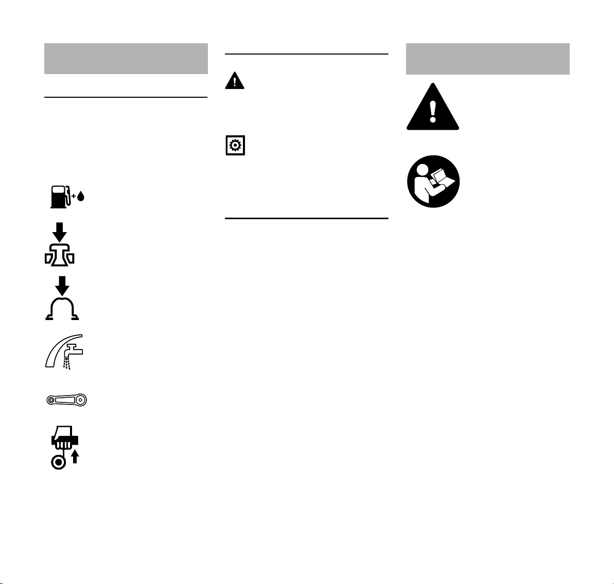
Pictograms
Pictograms that appear on the machine
are explained in this Instruction Manual.
Depending on the machine and
equipment version, the following
pictograms may appear on the machine.
Fuel tank; fuel mixture of
gasoline and engine oil
Actuate decompression
valve
Actuate manual fuel
pump
Water connection, shutoff cock
Tensioning nut for belt
Pull starter grip
Symbols in text
WARNING
Warning where there is a risk of an
accident or personal injury or serious
damage to property.
NOTICE
Caution where there is a risk of
damaging the machine or its individual
components.
Engineering improvements
STIHL's philosophy is to continually
improve all of its products. For this
reason we may modify the design,
engineering and appearance of our
products periodically.
Therefore, some changes, modifications
and improvements may not be covered
in this manual.
Safety Precautions and
Working Techniques
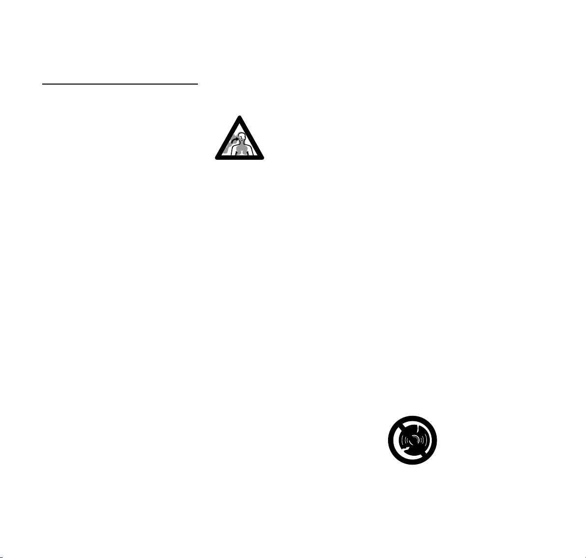
Special safety precau
tions must be taken when
working with the cut-off
machine, due to the very
high rotational speed of
the abrasive wheel.
It is important you read
and understand the User
Manual before commis
sioning and keep it in a
safe place for future ref
erence. Non-observance
of the safety precautions
may result in serious or
even fatal injury.
Observe all applicable local safety
regulations, e.g. by trade organizations,
social insurance institutions, labor safety
authorities etc.
As for employers within the European
Community, the provision 2009/104/EC
is binding – Safety and health protection
with the use of machines and devices by
employees at work.
If you have never used a power tool
before: have your STIHL dealer or other
specialist show you how to operate the
machine – or attend one of the special
training courses.
Minors should never be allowed to use
the machine – except for apprentices
over the age of 16 when working under
supervision.
Children, animals and bystanders must
not be allowed near the machine.
-
-
-
2
TS 700, TS 800

English
When not using the machine, it must be
laid down in such a way that it does not
endanger anyone. Ensure that the
machine cannot be used without
authorization.
The user is responsible for accidents or
risks involving third parties or their
property.
Do not lend or rent your power tool
without the User Manual. Be sure that
anyone using it understands the
information contained in this manual.
The use of machines that emit noise
may be limited to certain hours of the
day as specified by national and/or
regional or local regulations.
Anyone operating the machine must be
well rested, in good physical health and
in good mental condition.
If you have any condition that might be
aggravated by strenuous work, check
with your doctor before operating a
machine.
If you have a pacemaker: The ignition
system of your machine produces an
electromagnetic field of very low
intensity. This field may interfere with
some pacemakers. STIHL recommends
that persons with pacemakers consult
their physician and the pacemaker
manufacturer to reduce any health risk.
Anyone who has consumed alcohol or
drugs or medicines affecting their ability
to react must not operate a power tool.
Postpone the work if the weather is bad
(snow, ice, wind) – higher risk of
accidents!
The machine may only be used for
cutting. It is not suitable for cutting wood
or wooden objects.
Asbestos dust is extremely toxic - the
machine must therefore never be used
to cut asbestos!
Other uses are not permitted and may
lead to accidents or damage to the
machine.
Never attempt to modify your power tool
in any way since this may increase the
risk of personal injury. STIHL excludes
all liability for personal injury and
damage to property caused while using
unauthorized attachments.
Only use abrasive wheels or
accessories which have been approved
by STIHL for this machine or which are
technically equivalent. If you have any
questions in this respect, consult your
dealer. Only use high-quality abrasive
wheels and attachments. in order to
avoid the risk of accidents and damage
to the machine.
STIHL recommends the use of genuine
STIHL abrasive wheels and
accessories. They are specifically
designed to match the product and meet
your performance requirements.
Do not use a high-pressure washer to
clean the power tool. The solid jet of
water may damage parts of the unit.
Do not spray the power tool with water.
Never use circular saw
blades, carbide, rescue
or wood cutting attach
ments or saws of any
kind – these may cause
fatal injuries!Instead of
uniformly removing parti
cles as when cutting with
an abrasive wheel, the
teeth of a circular saw
blade may snag in the
material. This causes the
machine to react in a
highly aggressive manner
with uncontrolled and
extremely dangerous
kickback.
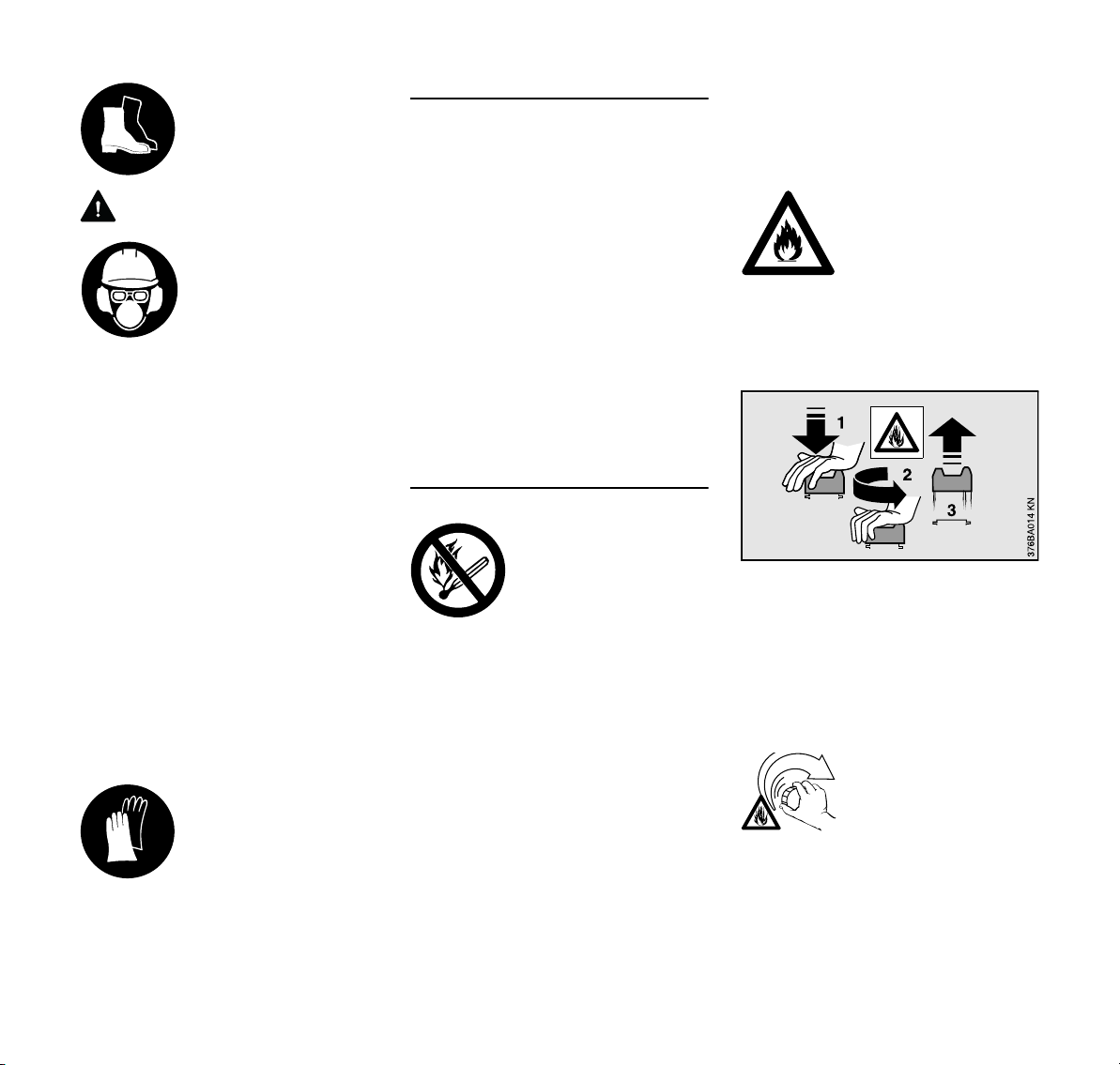
Clothing and equipment
Wear proper protective clothing and
equipment.
Clothing must be sturdy
but allow complete free
dom of movement. Wear
close-fitting clothes such
as a boiler suit, not a
work coat.
When cutting steel, always wear clothing
made of barely flammable material (e.g.,
leather or cotton with flame-retardant
finish) – no man made fibers – risk of fire
due to flying sparks!
Clothing must be free from flammable
deposits (chips, fuel, oil, etc.).
Do not wear clothes that may be caught
by moving parts – no scarf, no tie, no
jewelry. Tie up and confine long hair
above your shoulders.
-
-
-
TS 700, TS 800
3
English
Wear steel-toed safety
boots with non-slip soles.
WARNING
To reduce the risk of eye
injuries, wear close-fit
ting safety glasses in
accordance with Euro
pean Standard EN 166.
Make sure the safety
glasses are a snug fit.
Wear face protection and make sure it is
a good fit. Face protection alone is not
sufficient to protect the eyes.
Wear a safety hard hat where there is a
danger of head injuries from falling
objects.
Dust (e. g., crystalline material from the
object being cut), fumes and smoke may
be produced while cutting - health
hazard!
Always wear a dust mask if dust is
generated.
If fumes or smoke are anticipated (e. g.,
when cutting composite materials), wear
respiratory protection.
Wear "personal" hearing protection – for
example, ear defenders.
Wear sturdy protective
gloves made of a resist
ant material (e. g.
leather).
STIHL can supply a comprehensive
range of personal protective equipment.
-
-
-
Transporting the machine
Always stop the engine.
Carry the device by the handlebar only –
abrasive wheel pointing to the rear – hot
muffler away from the body.
To avoid serious burn injuries, avoid
touching hot parts of the machine,
especially the surface of the muffler.
Never transport the engine-driven
device with attached abrasive wheel –
risk of breakage!
By vehicle: When transporting in a
vehicle, properly secure your machine to
prevent turnover, damage and fuel
spillage.
Refueling
Gasoline is highly flam
mable – keep away from
fire or flame – do not spill
any fuel – no smoking.
Always shut off the engine before
refueling.
Do not fuel a hot engine – fuel may spill
and cause a fire.
Open the fuel cap carefully to allow any
pressure build-up in the tank to release
slowly and avoid fuel spillage.
Only refuel the machine in a well
ventilated place. If fuel has been spilled,
immediately clean the machine – do not
allow your clothes to be splashed with
fuel. If that happens, change your
clothes at once.
-
Dust may collect on the engine unit,
particularly around the carburetor. If dust
gets mixed with fuel – risk of fire. For this
reason, ensure that the dust is always
removed.
Check for fuel leakage!
Never start the engine if
fuel has been spilled or is
leaking – Fatal burns may
result!
Different cut-off machines may be
equipped with different fuel caps:
Bayonet-type fuel cap
Never use a tool to open or close the
bayonet-type fuel cap. This could
damage the cap and cause fuel to leak
out.
Close the bayonet-type fuel cap
carefully after refueling.
Threaded fuel cap
After fueling, tighten
down the screw-type fuel
cap as securely as
possible.
This helps reduce the risk of unit
vibrations causing an incorrectly
tightened fuel cap to loosen or come off
and spill quantities of fuel.
4
TS 700, TS 800
English
Cut-off machine, spindle bearing
Correct spindle bearings ensure the
concentricity and axial running of the
diamond abrasive wheel – if necessary,
get it checked by an approved dealer.
Abrasive cutting wheels
Selecting the abrasive cutting wheels
Abrasive cutting wheels must be
approved for freehand cutting. Do not
use other cutting wheels and
attachments – risk of accident!
Abrasive cutting wheels are suitable for
different materials: Observe the
identification of the abrasive cutting
wheels.
STIHL generally recommends wet
cutting.
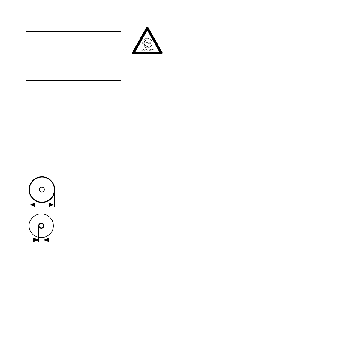
Observe the outer diame
ter of the abrasive wheel.
Spindle hole diameter of
the abrasive wheel and
shaft of cut-off machine
must match.
Check the spindle hole for damage. Do
not use abrasive cutting wheels with a
damaged spindle hole – risk of accident!
The permissible speed of
the abrasive cutting
wheel must be equal to or
greater than the maxi
mum spindle speed of the
cut-off machine. – Refer
to the chapter
"Specifications".
Before fitting a used abrasive cutting
wheel, check that it is not cracked,
chipped, undercut or uneven, and does
not display any signs of core fatigue or
overheating (discoloration); check also
the spindle hole is not damaged.
Never use cracked, chipped or bent
abrasive cutting wheels.
Substandard and/or unapproved
diamond abrasive wheels can shimmy
during cutting. This shimmying can
cause such diamond abrasive wheels to
be abruptly braked or become stuck in
the cut – Danger of kickback! Kickback
can result in fatal injuries! Diamond
-
abrasive wheels that shimmy constantly
or even only intermittently must be
replaced immediately.
Never straighten diamond abrasive
wheels.
Do not use an abrasive cutting wheel
which has fallen to the ground –
damaged abrasive cutting wheels may
break – risk of accident!
Observe the expiration date where
composite resin abrasive cutting wheels
are concerned.
Fitting abrasive cutting wheels
Inspect the spindle of the cut-off
machine. Do not use a cut-off machine if
the spindle is damaged – risk of
accident!
Note the arrows indicating the direction
of rotation on diamond abrasive wheels.
-
Position the front pressure plate –
tighten up the tensioning screw – rotate
the abrasive cutting wheel by hand and
take a sight check for concentricity and
axial running.
Storing cutting wheels
Store abrasive wheels in a dry and frost-
free place, on an even surface, at
constant temperature – risk of breakage
and splintering!
Always protect cutting wheels against
sudden impact with the floor or objects.
Before starting
Inspect the cut-off machine for safe-tooperate state – observe the respective
chapters in the User Manual:
– Check the fuel system for leaks,
especially the visible parts, e. g.,
fuel cap, hose connections, manual
fuel pump (only in machines with a
manual fuel pump). In case of
leakage and damage, do not start
the engine – risk of fire! Have the
machine serviced by a dealer
before using it
– The abrasive wheel must be
suitable for the material to be cut. It
must be in good condition and fitted
correctly (direction of rotation,
secure).
– Inspect the abrasive wheel guard
for tight seat – if loose, contact your
specialist dealer.
TS 700, TS 800
5
English
180BA022 KN
– Smooth action of throttle trigger and
throttle trigger lockout – throttle
trigger must return automatically to
idle position
– Slide control / master control lever /
stop switch must move easily to
STOP or 0
– Check that the spark plug boot is
secure – a loose boot may cause
sparking that could ignite
combustible fumes and cause a fire!
– Never attempt to modify the controls
or safety devices
– Keep the handles clean, dry and
free of oil as well as dirt – important
for safe guiding of the cut-off
machine.
– For wet applications, provide
sufficient water
To reduce the risk of personal injury, do
not operate your power tool if it is
damaged or not properly assembled!
Starting the engine
Start the engine at least 3 meters from
the fueling spot, outdoors only.
On even ground, ensure a firm and
secure footing and hold the enginedriven device firmly – the abrasive wheel
must not touch any objects or the ground
and must not be in cutting action.
The abrasive wheel may begin to rotate
as soon as the machine is started
The machine is operated by a single
person only – do not allow any person to
stay within the working area – nor with
starting.
Do not drop start your machine – the
correct starting procedure is described
in the User Manual.
After releasing the throttle trigger, the
abrasive wheel keeps on running for a
while – danger of injury due to coasting
effect!
Holding and guiding the machine
The cut-off machine may only be used
for hand-held cutting or when mounted
on a STIHL Cutquik cart.
Hand-held cutting
Always hold the machine firmly with both
hands: Right hand on the rear handle –
even if you are left-handed. To ensure
safe control, wrap your fingers tightly
around both handles.
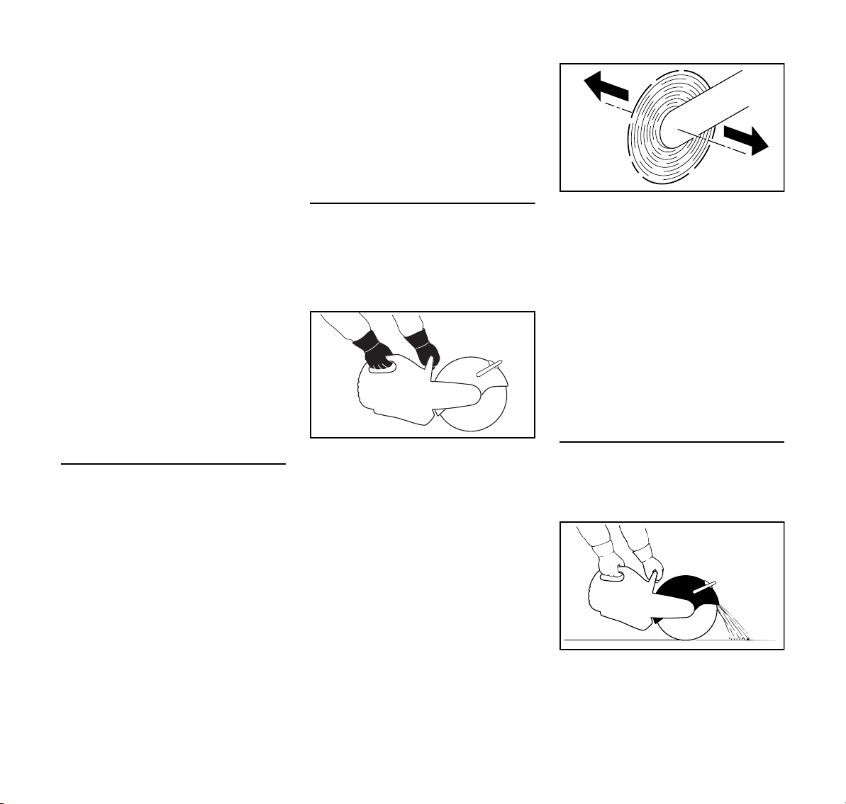
When a cut-off machine with an abrasive
cutting wheel rotating is moved in the
direction of the arrow, a force is
produced which causes the machine to
tip sideways.
The object to be cut off has to be firmly
supported. Always guide the machine
towards the workpiece – never the other
way round.
Cutquik cart
STIHL cut-off machines can be mounted
onto a STIHL Cutquik cart.
002BA549 AM
Deflector
The adjustment range of the guard is
determined by a stop pin. Never push
the guard over the stop pin.
Set the abrasive wheel guard correctly:
Guide particles of material away from
the user and machine.
002BA550 AM
6
TS 700, TS 800
English
Note the direction of flight of the
removed particles of material.
While working
If there is imminent danger or in an
emergency, immediately stop the
engine – set the slide control / master
control lever /stop switch to STOP or 0.
Check for correct idling, so that the
cutting wheel is no longer driven when
the throttle trigger is released and
comes to a complete halt.
Check and correct the idle speed setting
at regular intervals. Have the machine
repaired by a STIHL dealer if the cutting
wheel continues to turn nevertheless.
Keep clear the working area – bear in
mind obstacles, holes and pitches.
Take special care in slippery conditions
– damp, snow, ice, on slopes or uneven
ground.
Don not work while standing on a ladder
– not on an insecure support – not over
your shoulder height – not with one hand
only – risk of accident!
Make sure you always have good
balance and secure footing.
Do not work alone – keep within calling
distance of others in case help is
needed.
Keep out further persons from the
working area – maintain sufficiently large
distance to additional persons to protect
them from noise and flying objects.
Be particularly alert and cautious when
wearing hearing protection because
your ability to hear warnings (shouts,
alarms, etc.) is restricted.
Take a break in good time before you
get tired.
Work calmly and carefully – in daylight
conditions and only when visibility is
good. Proceed with caution, do not put
others in danger.
As soon as the engine is
running, the power
machine generates toxic
exhaust gas. These
gases may be odorless
and invisible and may
contain unburned hydro
carbons and benzene.
Never run the engine
indoors or in poorly venti
lated locations, even if
your model is equipped
with a catalytic converter.
Ensure proper ventilation when working
in trenches, hollows or similar locations
– risk of fatal injury from breathing toxic
fumes!
Stop work immediately if you start
suffering from nausea, headaches,
impaired vision (e.g. your field of vision
gets smaller), impaired hearing,
dizziness, or impaired concentration –
these symptoms may possibly be the
result of too-high exhaust gas
concentration – Risk of accidents!
To reduce the risk of fire, do not smoke
while operating or standing near your
power tool.
If your power tool is subjected to
unusually high loads for which it was not
designed (e.g. heavy impact or a fall),
always check that it is in good condition
before continuing work – see also
"Before Starting". Check in particular
that the fuel system has no leaks and the
-
safety equipment is fully operative.
Never use a power tool that is no longer
safe to operate. In case of doubt, contact
a dealer.
Do not operate your power tool in the
starting throttle position – engine speed
cannot be controlled in this position.
Never touch a rotating abrasive cutting
wheel with your hand or any other part of
your body.
Examine the workplace. Avoid all
danger due to damaged piping or
electrical wiring.
The machine must not be used near
inflammable substances or gases.
-
Do not cut into pipes, metal tanks or
other containers if you are not sure that
they do not contain any volatile or
inflammable substances.
Never leave the machine unattended
with the engine running. Stop the engine
before leaving the machine unattended
(e. g. for breaks).
Before putting the cut-off machine down
on the ground:
– Shut off the engine
– Wait until the abrasive cutting wheel
has come to a standstill or brake the
abrasive cutting wheel until it comes
to a standstill by carefully touching a
hard surface (e.g., concrete slab)
Frequently inspect the
abrasive cutting wheel –
replace it right away if
there are visible cracks,
buckling or other damage
(for example, overheat
ing) – risk of accident due
to breakage!
-
TS 700, TS 800
7
English
002BA552 AM
In the event of changes in cutting
behavior (e. g., increased vibration,
reduced cutting performance), stop work
and eliminate the causes of the
changes.
Reactive forces
The most frequently occurring reactive
forces are kickback and pull-in.
Danger of kickback –
Kickback can result in
fatal injuries.
Kickback occurs when the cut-off
machine is suddenly thrown up and back
in an uncontrolled arc towards the
operator.
Kickback occurs if, for example, the
abrasive cutting wheel
– gets jammed – primarily in its upper
quarter, or
– is abruptly braked through friction
contact with a solid object
To reduce the risk of kickback
– Work cautiously and avoid
situations which could cause
kickback.
– Hold the cut-off machine firmly with
both hands and maintain a secure
grip
– If possible, avoid using the upper
quarter of the abrasive cutting
wheel for cutting. Use extreme
caution when guiding the abrasive
cutting wheel into a cut, do not twist
or push into the cut
002BA551 AM
– Avoid any wedge effect - the
severed part must not brake the
abrasive cutting wheel
– Always be aware that the object to
be cut may move and other factors
may cause the cut to close and jam
the abrasive cutting wheel.
– The object to be cut must be
secured and supported so that the
kerf remains open during and after
cutting
– Objects to be cut must therefore be
fully supported and must be
secured against rolling away,
slipping off or vibrations
– Support an uncovered pipe stable
and solid, if necessary, use wedges
– always bear in mind a proper
support and ground – material may
crumble away,
– Always work with water and wet
cutting when using diamond
abrasive wheels
– Depending on the version,
composite resin abrasive cutting
wheels are suitable only for dry
cutting or only for wet cutting.
Always use wet cutting with
002BA555 AM
composite resin abrasive cutting
wheels that are suitable only for wet
cutting
002BA556 AM
8
TS 700, TS 800
English
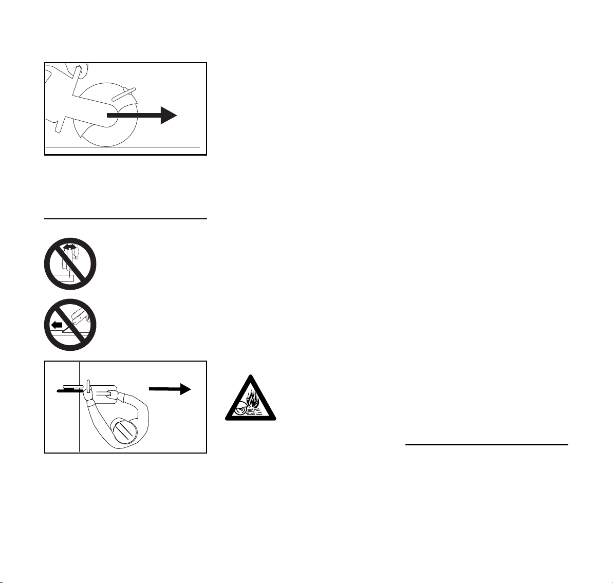
Pull away from
The cut-off machine pulls forward, away
from the user, when the abrasive wheel
touches the object to be cut from above.
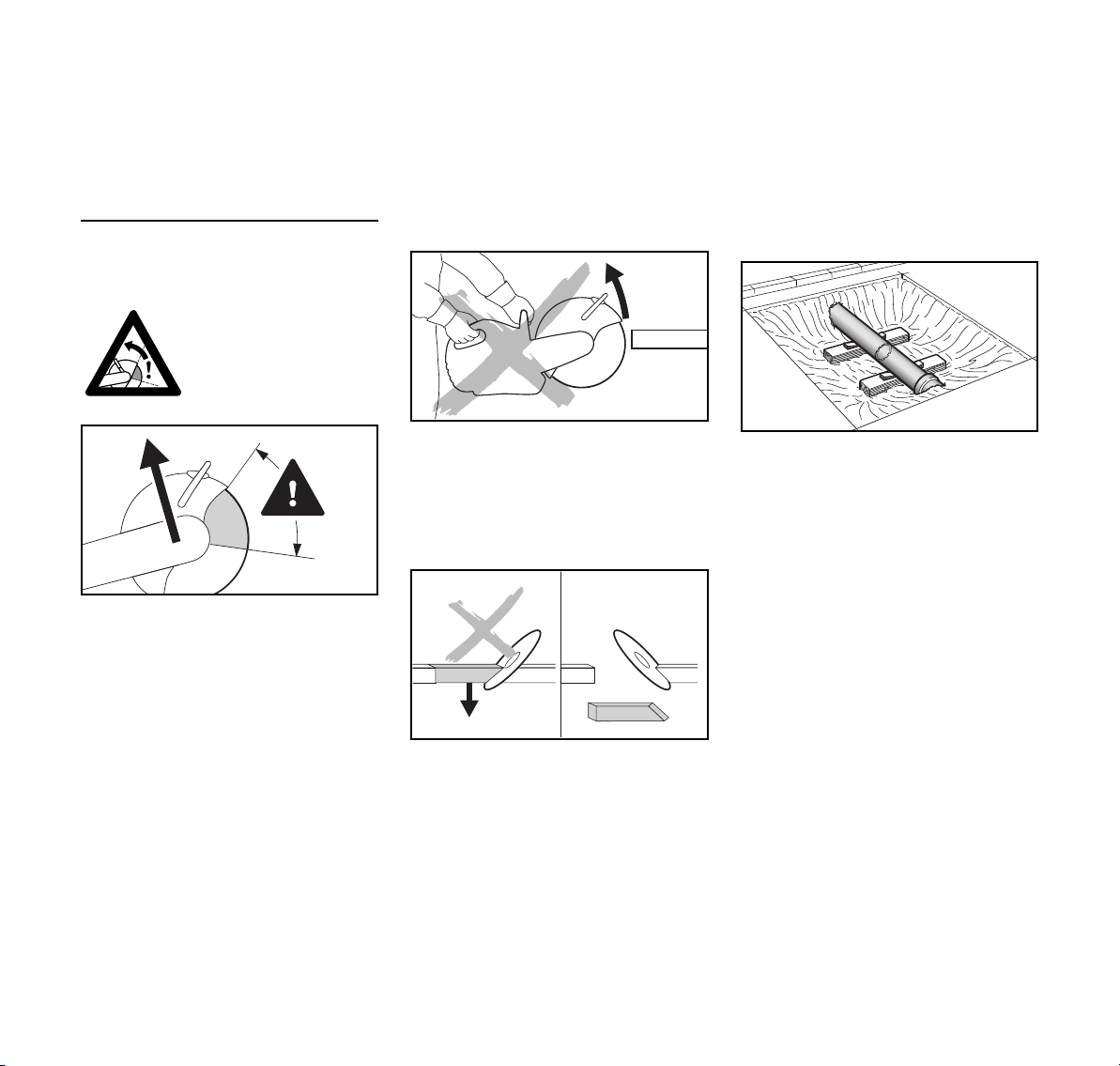
Working – cutting off
The cutting wheel must
be guided straight in the
cut, without wedging.
Never exert lateral pres
-
sure on the cutting wheel.
Do not use for lateral
grinding or scrubbing.
Do not lean too far forwards and never
bend over the abrasive wheel when the
guard has been pulled back.
Do not work above shoulder height.
The cut-off machine may only be used
for cutting. It must not be used as a lever
or shovel.
Do not press down on the cut-off
machine
002BA553 AM
Always decide the cutting direction
before positioning the cut-off machine.
After that, do not change the cutting
direction. Never push or hit with the
device into the cutting gap – do not let
the concrete cutter fall into the cutting
depth – risk of breakage!
Diamond abrasive wheels: If cutting
performance begins to deteriorate,
check the sharpness of the diamond
cutting wheel, resharpen as needed. To
do this, briefly cut through abrasive
material, e. g., sandstone, aerated
concrete or asphalt.
At the end of the cut, the cut-off machine
is no longer supported by the abrasive
wheel in the cut. The user has to absorb
the weight force – risk of loss of control!
When cutting steel: glow
ing metal particles may
cause fires!
When applying diamond abrasive
wheels, take a wet cut – for example,
use the STIHL water connector.
Depending on the version, composite
resin abrasive cutting wheels are
suitable only for dry cutting or only for
wet cutting.
When using composite resin abrasive
cutting wheels which are suited for wet
cuts only, take such wet cuts only – for
example, use the STIHL water
connector.
When using composite resin abrasive
cutting wheels which are suited for dry
cuts only, take such dry cuts only. If
however composite resin abrasive
cutting wheels of this type become wet,
their cutting performance is reduced and
they become dull. If composite resin
abrasive cutting wheels of this type
become wet while working (e. g., due to
puddles or water in pipes), do not
increase the cutting pressure, but
continue working with the same
pressure – risk of breakage! Use up
such composite resin abrasive cutting
wheels immediately.
Cutquik cart
-
Clear a path for the Cutquik cart. If the
Cutquik cart is pushed over objects, the
abrasive wheel may become wedged in
the cut and shatter!
Do not stand in line with the abrasive
wheel. Ensure sufficient freedom of
movement, especially in construction
trenches there must be sufficient space
for the user and for the part being cut to
fall.
TS 700, TS 800
Keep water and sludge away from alive
electrical cables – risk of electric shock!
002BA554 AM
Drag the abrasive wheel into the
workpiece – do not push it into the
material. Do not correct severing cuts
with the cut-off machine. Do not re-cut –
remove left webs or breaking edges (for
example, with a hammer).
Vibrations
Prolonged use of the power tool may
result in vibration-induced circulation
problems in the hands (whitefinger
disease).
9

English
No general recommendation can be
given for the length of usage because it
depends on several factors.
The period of usage is prolonged by:
– Hand protection (wearing warm
gloves)
– Work breaks
The period of usage is shortened by:
– Any personal tendency to suffer
from poor circulation (symptoms:
frequently cold fingers, tingling
sensations).
– Low outside temperatures.
– The force with which the handles
are held (a tight grip restricts
circulation).
Continual and regular users should
monitor closely the condition of their
hands and fingers. If any of the above
symptoms appear (e.g. tingling
sensation in fingers), seek medical
advice.
Maintenance and repairs
The machine must be serviced regularly.
Do not attempt any maintenance or
repair work not described in the
Instruction Manual. All other work should
be carried out by a servicing dealer.
STIHL recommends that maintenance
and repair work be carried out only by
authorized STIHL dealers. STIHL
dealers receive regular training and are
supplied with technical information.
Use only high-quality replacement parts,
in order to avoid the risk of accidents or
damage to the machine. Contact a
dealer if in doubt.
STIHL recommends the use of genuine
STIHL spare parts. Such parts have
been optimized for the machine and the
user's requirements.
Before starting any maintenance or
repair work and before cleaning the
machine, always stop the engine and
disconnect the spark plug boot – risk of
injury if the engine starts up
inadvertently! – Exception: adjustment
of carburetor and idle speed.
To reduce the risk of fire due to ignition
outside the cylinder, move the slide
control / stop switch to STOP or 0 before
turning the engine over on the starter
with the spark plug boot removed or the
spark plug unscrewed.
Do not service or store the machine near
a naked flame – risk of fire due to the
fuel.
Check fuel cap regularly for tightness.
Use only spark plugs that are in perfect
condition and have been approved by
STIHL – see Specifications.
Inspect ignition lead (insulation in good
condition, secure connection).
Check that the muffler is in perfect
working condition.
Do not use the machine if the muffler is
damaged or missing - risk of fire! –
Hearing damage!
Never touch a hot muffler – risk of burns!
Check the rubber buffers underneath
the machine - the housing must not rub
against the ground - risk of damage!
The condition of the antivibration
elements influences vibration behavior –
inspect antivibration elements
periodically.
Maintenance, replacement, or repair of
the emission control devices and
systems may be performed by any
nonroad engine repair establishment or
individual. However, if you make a
warranty claim for a component which
has not been serviced or maintained
properly, STIHL may deny coverage.
For any maintenance please refer to the
maintenance chart and to the warranty
statement near the end of the instruction
manual.
10
TS 700, TS 800
English
Sample Applications
Water must always be used for wet
cutting when working with diamond
abrasive wheels
Extend service life and increase cutting
speed
Always ensure a supply of water to the
abrasive wheel.
Binding dust
The abrasive wheel must be supplied
with at least 0.6 liters of water per
minute.
Water attachment
– Water attachment on the machine
for all types of water supplies
– Pressurized water tank 10 l for
binding dust
– water tank usable on the cut-off
machine cart for binding dust
Use composite resin abrasive wheels
with or without water – depending on
version
If fumes or smoke are anticipated (e. g.,
when cutting composite materials), wear
respiratory protection.
Composite resin abrasive wheels
suitable only for wet cutting
Use abrasive wheel only
with water.
To bind dust, the abrasive wheel must
be supplied with at least 1 liter of water
per minute. To avoid a reduction in
cutting performance, the abrasive wheel
must be supplied with not more than
4 liters of water per minute.
After using the abrasive wheel, the
wheel should be allowed to continue
spinning at operating speed for
approx. 3 to 6 seconds without water in
order to spin off the water remaining on
it.
– Water attachment on the machine
for all types of water supplies
– Pressurized water tank 10 l for
binding dust
– water tank usable on the cut-off
machine cart for binding dust
Severed parts
With openings, recesses, etc., the
sequence of the cuts is important.
Always make the last cut so that the
abrasive wheel does not become
jammed and so that the operator is not
endangered by the severed or
separated part.
If necessary, leave small ridges that hold
the part that is to be separated in
position. Break these ridges later.
Before finally separating the part,
determine:
– how heavy the part is
– how it can move after separation
– whether it is under tension
When breaking out the part, do not
endanger assistants.
Cut in several passes
Depending on the version, resin
abrasive wheels are only suitable for dry
cutting or only for wet cutting.
Composite resin abrasive wheels
suitable only for dry cutting
During dry cutting, wear a suitable dust
mask.
TS 700, TS 800
Observe with diamond and composite
resin abrasive wheels
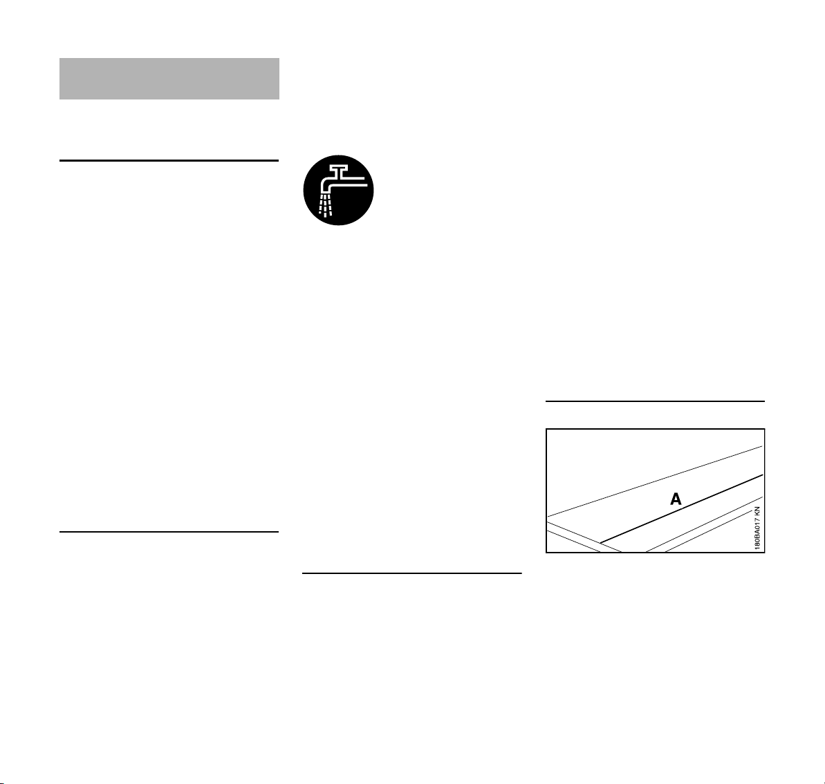
Objects to be cut
– Must be fully supported
– Must be secured so it cannot roll or
slip off
– Must be prevented from vibrating
N Mark cutting line (A)
11
English
N Work along the cutting line. When
making corrections, do not tilt the
abrasive wheel, but always set the
abrasive wheel against the
workpiece anew – the cutting depth
for each operation should not
exceed 5 to 6 cm. Cut thicker
material in multiple operations
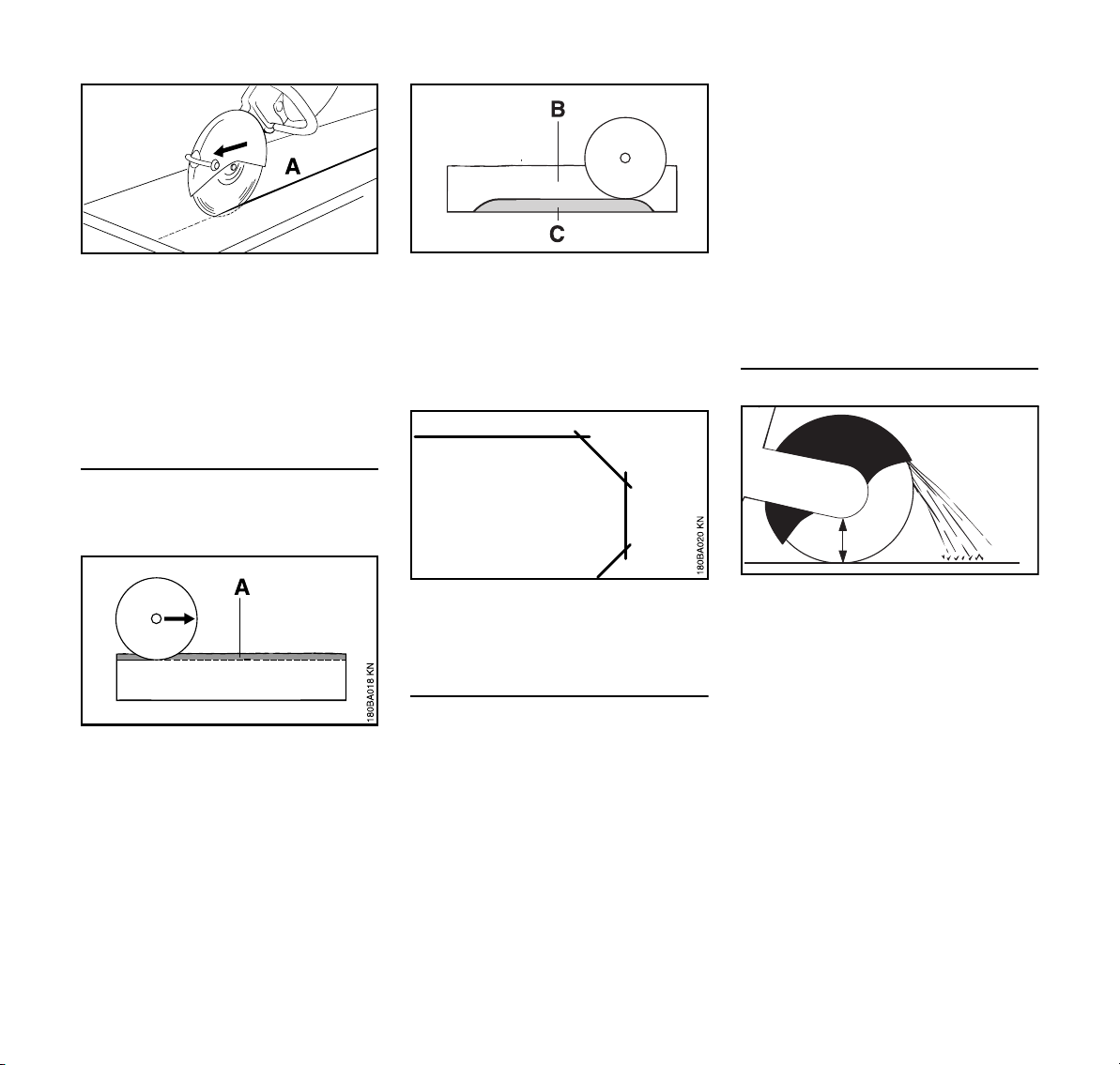
Cutting plates
N Secure the plate (e. g. on a non-slip
surface, sandbed)
N Grind a guide groove (A) along the
line marked
180BA027 AM
N Make the cut (B) deeper
N Leave a "hinge" (C)
N First sever the plate at the cut ends
so that no material breaks away
N Break plate
N Make curves in multiple operations
– make certain that the abrasive
wheel does not tilt
Cutting pipes, round and hollow bodies
N Secure pipes, round and hollow
bodies against vibrations, slipping
and rolling away
N Note direction of fall and weight of
the severed part
N Determine and mark the cutting line,
avoid reinforcement, especially in
the direction of the severing cut
N Determine sequence of severing
cuts
N Grind a guide groove along the line
marked
N Make cut deeper along the guide
groove – observe the recommended
cutting depth for each operation –
for small corrections of direction, do
not tilt the abrasive wheel, but
180BA028 AM
always position it anew instead – if
necessary, leave small ridges that
hold the part that is to be separated
in position. Break these ridges after
the last planned cut
Cutting concrete pipe
A
The procedure is dependent on the
outer diameter of the pipe and the
maximum possible cutting depth of the
abrasive wheel (A).
N Secure pipe against vibrations,
slipping and rolling away
N Note weight, tension and direction
of fall of the part to be severed
002BA557 AM
12
TS 700, TS 800
English
002BA559 AM
N Determine and mark direction of cut
N Determine sequence of cuts
Outer diameter is smaller than the
maximum cutting depth
N Make one cut from the top to the
bottom
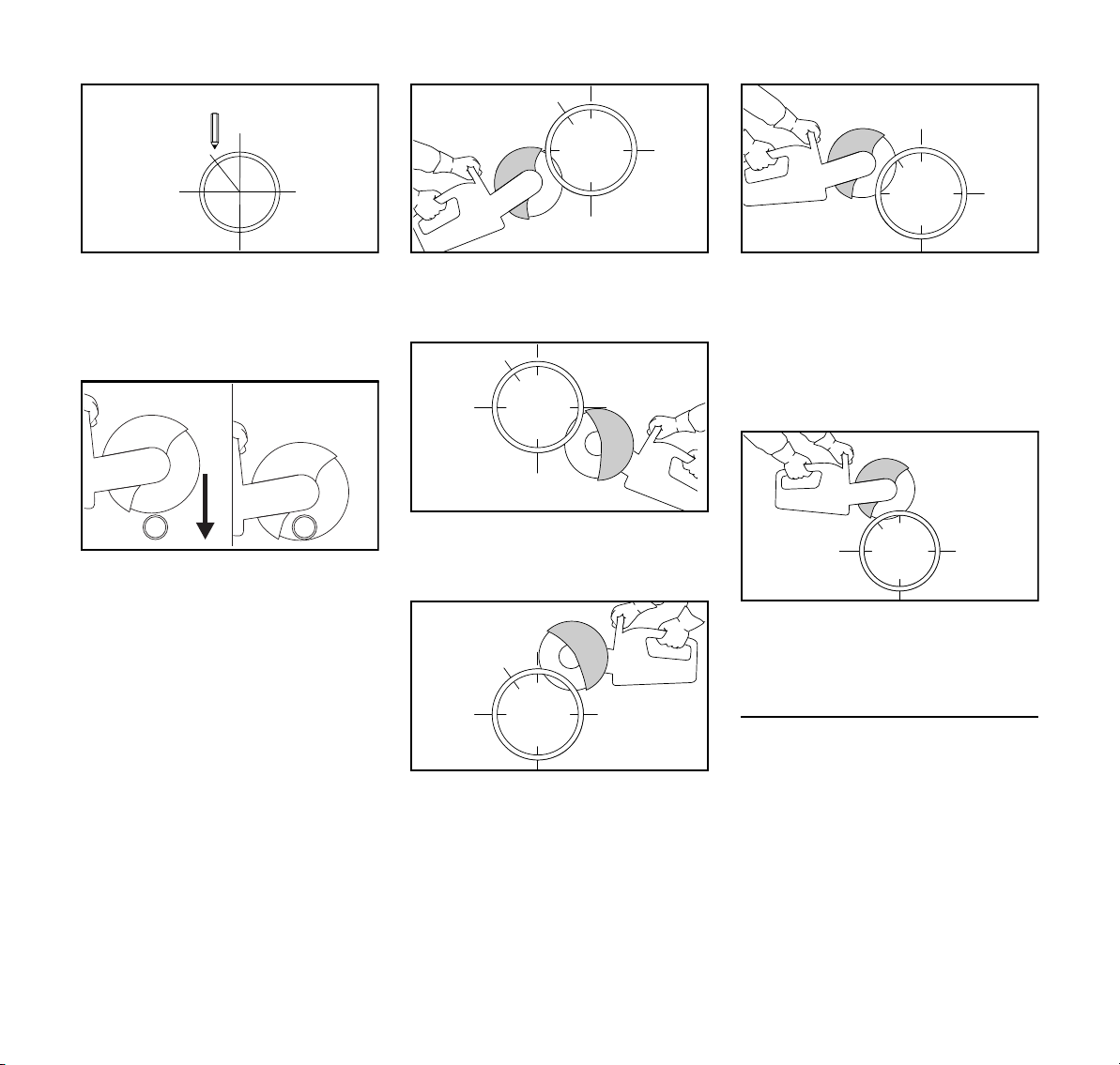
Outer diameter is greater than the
maximum cutting depth
Plan first, then cut. Several cuts are
needed – correct sequence is important.
N Turn guard at rear stop
002BA528 AM
N Always start at the bottom, use the
upper quarter of the abrasive wheel
for cutting
N Use the upper quarter of the
002BA558 AM
abrasive wheel for cutting the
opposite lower side.
N First lateral cut on the top half of the
pipe
002BA560 AM002BA561 AM002BA562 AM
N Second lateral cut in the marked
area – never cut into the area of the
last cut, to ensure a firm hold on the
part of pipe to be cut
Only make the last top cut once all
bottom and lateral cuts have been
made.
N Last cut always from the top
(approx. 15 % of the pipe
circumference)
Concrete pipe – cut recess
Sequence of cuts (1 to 4) is important:
N First, cut hard-to-reach areas
002BA563 AM
TS 700, TS 800
13
English
1
2
N Always make severing cuts so that
the abrasive wheel is not pinched
N Use wedges and/or leave ridges
that are broken after cutting
4
3
N If the severed part remains in the
recess after cutting (due to wedges,
ridges used), do not make any
further cuts – break the severed part
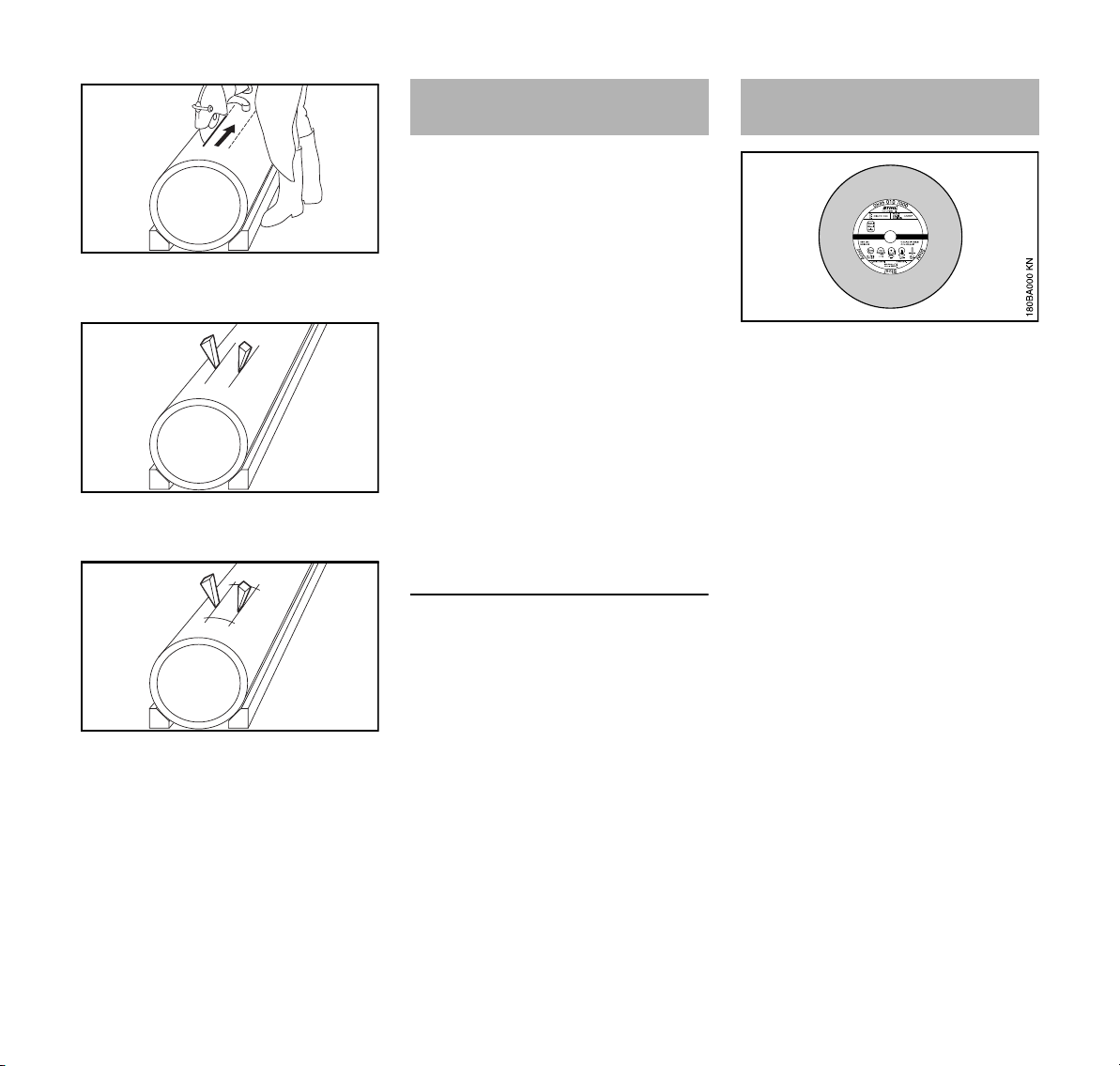
Cutting Wheels Composite Abrasive Wheels
Abrasive wheels are exposed to
extremely high loads especially during
freehand cutting.
Therefore only for use of approved and
correspondingly labeled abrasive
180BA024 AM180BA025 AM180BA026 AM
wheels with hand-held machines as per
EN 13236 (diamond) or EN 12413
(composite resin). Note maximum
permissible speed of the abrasive wheel
– risk of accident!
The abrasive wheels, which have been
developed by STIHL in cooperation with
renowned manufacturers of abrasive
wheels, are of high quality and tailored
precisely to the respective intended use
as well as the engine performance of the
cut-off machine.
They are of consistently outstanding
quality.
Transport and storage
– Do not expose abrasive wheels to
direct sunshine or other thermal
stresses during transport and
storage
– Avoid jolting and impacts
– Stack abrasive wheels flat on a level
surface in the original packaging in
a dry place where the temperature
is as constant as possible
– Do not store abrasive wheels in the
vicinity of aggressive fluids
– Store abrasive wheels in a fr ost-fr ee
place
Types:
– for dry applications
– for wet applications
The proper selection and use of
composite resin cutting wheels ensures
economical use and avoids accelerated
wear. The product code which appears
– on the label and
– on the packaging (table with
recommendations for use) is an aid
to selection
STIHL composite resin cutting wheels
are suitable, depending on the version,
for cutting the following materials:
– Asphalt
– Concrete
– Stone
– Ductile cast iron pipes
– Steel; STIHL composite resin
cutting wheels are not suitable for
cutting railway tracks
Do not cut any other materials – risk of
accident!
14
TS 700, TS 800

English
0000-GXX-1235-A0
D-B10
Diamond Abrasive Wheels
For wet applications.
The proper selection and use of
diamond abrasive wheels ensures
economical use and avoids accelerated
wear. The product code which appears
– on the label and
– on the packaging (table with
recommendations for use) is an aid
to selection
STIHL diamond abrasive wheels are
suitable, depending on the version, for
cutting the following materials:
– Asphalt
– Concrete
– Stone (hard stone)
– Abrasive concrete
– Fresh concrete
– Clay brick
– Clay pipe
– Ductile cast iron pipe
Do not cut any other materials – Risk of
accident!
Never use diamond abrasive wheels
with side plating as they jam in the cut
and can result in extreme kickback –
Risk of accident!
Product Codes
The product code is a combination of
letters and numbers, consisting of up to
four characters:
– the letters denote the main field of
application of the abrasive wheel
– the numbers denote the
performance class of the STIHL
diamond abrasive wheel
Axial and radial run-out
A faultless spindle bearing of the cut-off
machine is necessary for a long service
life and efficient functioning of the
diamond abrasive wheel.
Using the abrasive wheel on a cut-off
machine with a faulty spindle bearing
can lead to deviations in radial and axial
run-out.
An excessively high radial run-out
deviation (A) overloads individual
diamond segments, which overheat in
the process. This can lead to stress
cracks in the parent wheel or to
annealing of individual segments.
Deviations in axial run-out (B) result in
higher thermal loading and wider cuts.
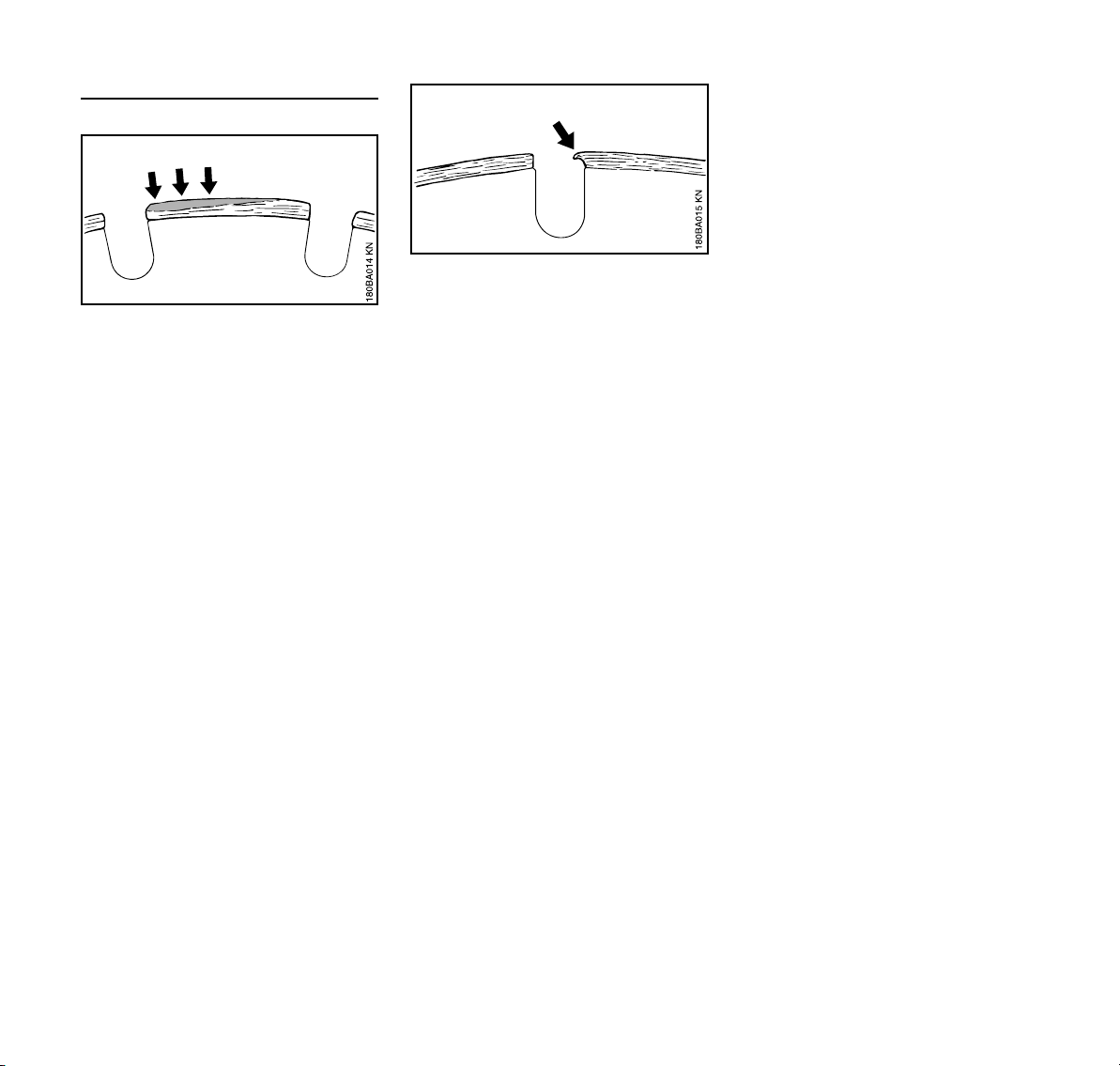
Undercut
Do not cut into the base course
(frequently chipped stones and gravel)
when cutting roadway pavement –
cutting in chipped stones and gravel is
revealed by light-colored dust –
excessive undercut may occur as a
result – Danger of shattering!
TS 700, TS 800
15
English
Built-up edges, sharpen
Built-up edges take the form of a light
gray deposit on the tops of the diamond
segments. This deposit on the segments
clogs the diamonds and blunts the
segments.
Built-up edges can form:
– when cutting extremely hard
materials, e. g., granite
– with incorrect handling, e. g.,
excessive feed effort
Built-up edges increase vibration,
reduce cutting performance, and cause
formation of sparks.
At the first signs of built-up edges,
immediately "sharpen" the diamond
abrasive wheel – to do this, briefly cut
through abrasive material such as
sandstone, aerated concrete or asphalt.
Addition of water prevents the formation
of built-up edges.
If work continues with dull segments,
these may soften due to the high heat
generated – the parent wheel is
annealed and its strength is
compromised – this can lead to stresses
that are clearly recognizable by
gyrations of the abrasive wheel. Do not
continue to use the abrasive wheel –
Risk of accident!
16
TS 700, TS 800

Troubleshooting
Abrasive wheel
English
Defects Cause Remedy
ragged edges or cut surfaces, crooked
Deviation in radial or axial run-out Contact a servicing dealer
1)
cut
heavy wear on the sides of the segments Abrasive wheel gyrates use a new abrasive wheel
ragged edges, crooked cut, no cutting
performance, generation of sparks
Abrasive wheel is dull; built-up edges with
abrasive wheels for stone
Sharpen abrasive wheels for stone by
briefly cutting through abrasive materials;
replace abrasive wheel for asphalt with a
new one
poor cutting performance, high segment
wear
Breakdowns or tears in the parent wheel
Abrasive wheel is turning in the wrong
direction
Mount abrasive wheel so that it turns in
the right direction
Overloading use a new abrasive wheel
and segment
Undercut Cutting in the wrong material use new abrasive wheel; observe sepa
rating layers of various materials
1)
STIHL recommends STIHL servicing dealers
-
TS 700, TS 800
17

English
3
1
1
2
376BA079 KN
376BA080 KN
1
2
3
1
1
1
2
376BA091 KN
Assembling the bearing and
guard
The "support with guard" is mounted on
the inboard side by the manufacturer.
The "support with guard" can also be
mounted on the outboard side
depending on requirements.
Assembly on the inboard side is
recommended for freehand cutting on
account of the better balance.
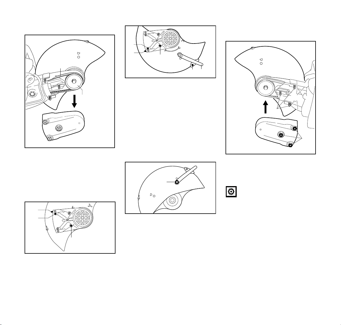
Outboard mounting (TS 700)
N Disassemble the abrasive wheel
(see “Fitting / replacing an abrasive
wheel”)
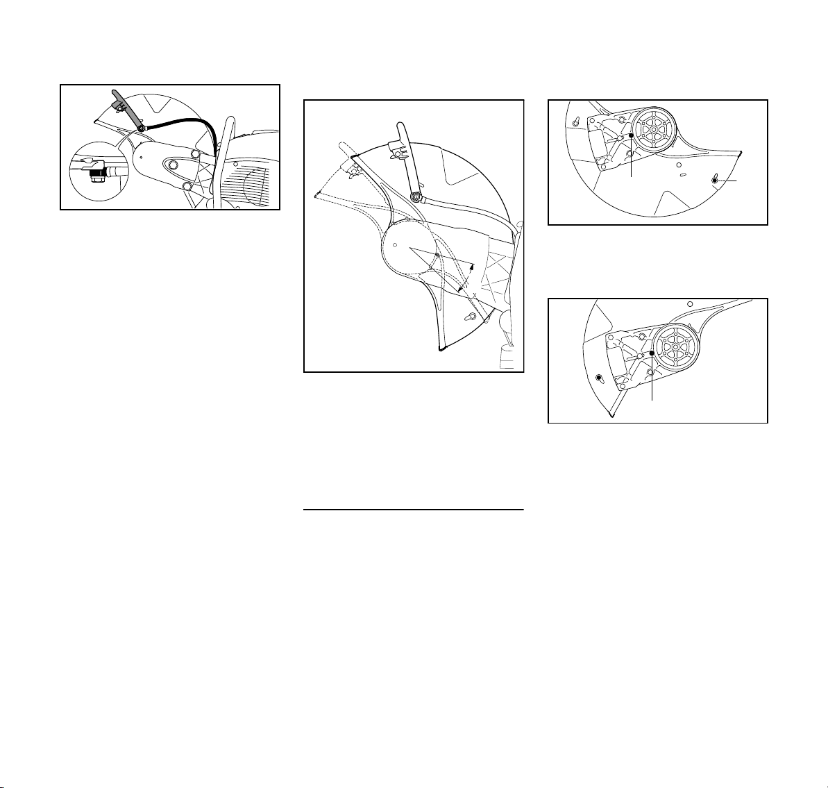
Removing the water attachment
Removing the adjusting lever
N Unscrew the banjo bolt (1) with the
combination wrench and remove it
together with the seal – in the
process, remove the square nut
from the inside of the guard from the
guide
N Unscrew the screw (2)
N Turn the adjusting lever (3) upwards
and remove
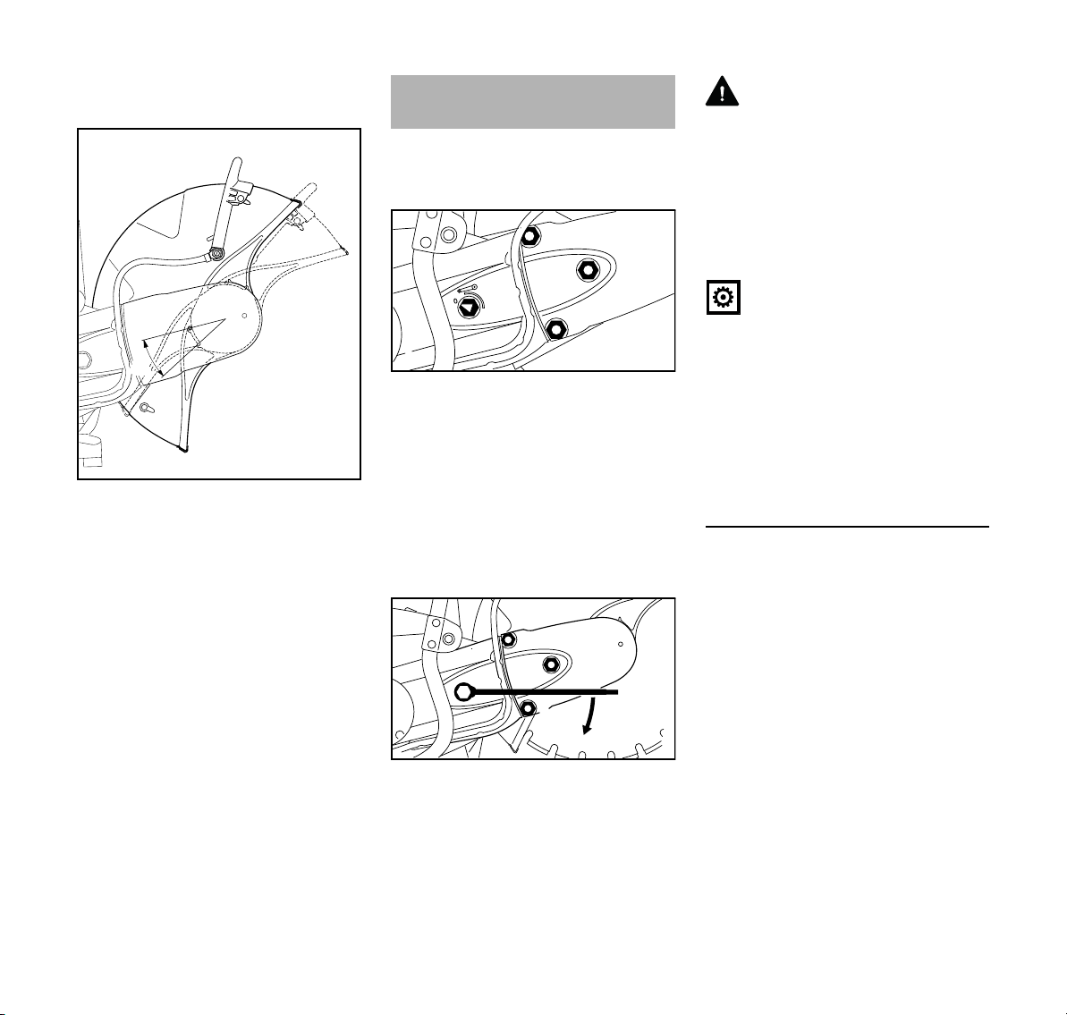
Slackening the V-belt
N To relax the poly V-belt, loosen the
nuts (1) – do not unscrew the
nuts (1) from the studs
N Turn the tensioning nut (2)
counterclockwise with the
combination wrench –
approx. 1/4 turn, as far as it will
go = 0
N Unscrew nuts (1) from the studs –
nuts (1) are fastened to the belt
guard so that they are secured
against loss
N Unscrew the banjo bolt (1) with the
combination wrench – in the
process, remove the square nut
from the inside of the guard from the
guide
N Remove the water hose (2) with
connector from the adjusting
lever (3)
18
TS 700, TS 800
English
3
2
376BA092 KN
4
1
3
376BA083 KN
1
2
376BA084 KN
1
2
3
4
5
A
376BA085 KN
6
1
376BA093 KN
2
4
3
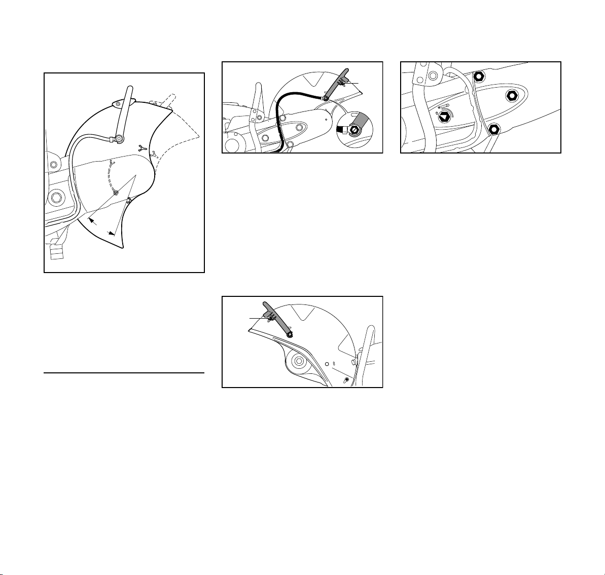
Removing the V-belt guard
N Turn the guard so that it is in the
position shown (see picture)
N Screw in and tighten the stop pin (3)
N Insert limit stop (2) – align the hole
in the limit stop with the hole in the
bearing
N Insert and tighten the screw (1)
N Move the adjusting lever (4) to
position A
N Pull the V-belt guard (1) off and
remove the V-belt (2) from the front
pulley (3)
N Remove the "support and guard" (4)
Preparing the "support with guard" for
outboard mounting
N Unscrew the screw (1) of the limit
stop (2)
N Remove the limit stop (2)
N Unscrew the stop pin (3)
TS 700, TS 800
N Insert and tighten the screw (5)
N Turn the "support with guard" so
that the guard is on the outboard
side
N Insert the square nut into the guide
in the guard and hold it in place
N Screw in the shorter banjo bolt (6)
and washer at the adjusting lever
and tighten up with the combination
wrench
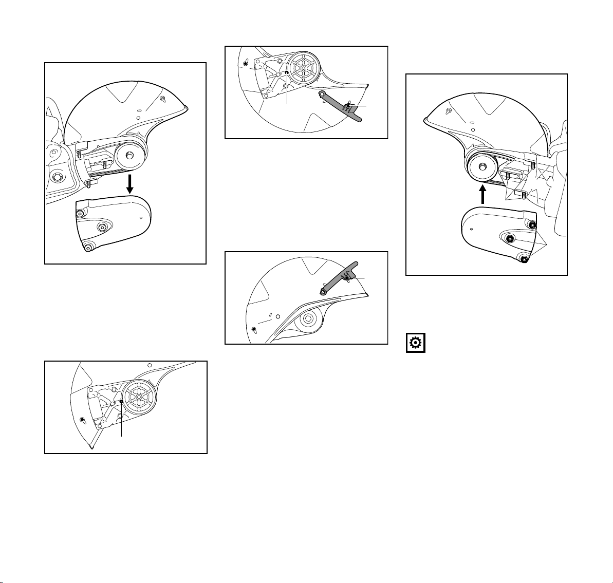
Mounting "support with guard" – guard
on the outboard side
N Fit the "support with guard" (1) on
the outboard side of the cast arm at the same time, guide the V-belt
over the belt pulley
NOTICE
The belt action must run smoothly.
N Position the V-belt guard (2)
N Align studs (3) in support with
nuts (4) in the V-belt guard
N Screw nuts (4) onto studs (3) – do
not tighten them yet
19

English
2
1
1
376BA087 KN
3
376BA088 KN
A
376BA089 KN
1
2
3
3
376BA083 KN
1
2
Connecting the water connection
N Insert the longer banjo bolt (1)
through the connector (2) of the
water attachment – observe the
position of the connector
N Insert the square nut into the guide
in the guard and hold it in place
N Fit the support with the longer banjo
bolt on the adjusting lever (3) –
screw in the banjo bolt and tighten
with the combination wrench
20
Checking the adjustment range of the
guard
N Rotate the guard forwards and
backwards as far as possible –
adjustment range (A) must be
limited by the stop pin
Continue as described in the chapter
“Tensioning the V-belt”.
Inboard mounting (TS 700)
N Disassemble the abrasive wheel
(see “Fitting / replacing an abrasive
wheel”)
N Remove the water attachment
N Remove the adjusting lever
N Slacken the V-belt
N Remove the V-belt guard
N Remove "support with guard"
Preparing the "support with guard" for
inboard mounting
N Unscrew the screw (1) of the limit
stop (2)
N Remove the limit stop (2)
N Unscrew the stop pin (3)
N Turn the guard so that it is in the
position shown (see picture)
N Screw in and tighten the stop pin (3)
N Insert limit stop (2) – align the hole
in the limit stop with the hole in the
bearing
N Insert and tighten the screw (1)
N Install the adjusting lever
N Mount "support with guard" – guard
on the inboard side
N Install the V-belt guard
N Connect the water connection
TS 700, TS 800
English
A
376BA090 KN
3
2
1
377BA013 KN
4
4
3
377BA014 KN
1
2
1
1
2
1
377BA015 KN
Checking the adjustment range of the
guard
N Rotate the guard forwards and
backwards as far as possible –
adjustment range (A) must be
limited by the stop pin
Continue as described in the chapter
“Tensioning the V-belt”.
Removing the water attachment
N Unscrew the banjo bolt (1) with the
combination wrench – in the
process, remove the square nut
from the inside of the guard from the
guide
N Remove the water hose (2) with
connector from the adjusting
lever (3)
N Unscrew the screw (4)
Removing the adjusting lever
Slackening the V-belt
N To relax the poly V-belt, loosen the
nuts (1) – do not unscrew the
nuts (1) from the studs
N Turn the tensioning nut (2)
counterclockwise with the
combination wrench –
approx. 1/4 turn, as far as it will
go = 0
N Unscrew nuts (1) from the studs –
nuts (1) are fastened to the belt
guard so that they are secured
against loss
Outboard mounting (TS 800)
N Disassemble the abrasive wheel
(see “Fitting / replacing an abrasive
wheel”)
TS 700, TS 800
N Unscrew the banjo bolt (1) with the
combination wrench and remove it
together with the seal – in the
process, remove the square nut
from the inside of the guard from the
guide
N Unscrew the screw (2)
N Turn the adjusting lever (3) upwards
and remove
N Remove the sealing plug (4)
21
English
2
377BA016 KN
1
3
4
2
377BA017 KN
1
2
A
4
3
1
377BA018 KN
2
5
377BA019 KN
4
377BA020 KN
2
1
4
3
Removing the V-belt guard
N Pull the V-belt guard (1) off and
remove the V-belt (2) from the front
pulley (3)
N Remove the "support and guard" (4)
Preparing the "support with guard" for
outboard mounting
N Unscrew the stop pin (1)
N Remove the sealing plug (2)
22
N Turn the guard so that it is in the
position shown (see picture)
N Screw in and tighten the stop pin (1)
N Insert the sealing plug (2)
N Move the adjusting lever (3) to
position A
N Insert and tighten the screw (4)
N Turn the "support with guard" so
that the guard is on the outboard
side
N Insert the square nut into the guide
in the guard and hold it in place
N Screw in the shorter banjo bolt (5)
and washer at the adjusting lever
and tighten up with the combination
wrench
N Insert the sealing plug (2)
N Insert and tighten the screw (4)
Mounting "support with guard" – guard
on the outboard side
N Fit the "support with guard" (1) on
the outboard side of the cast arm at the same time, guide the V-belt
over the belt pulley
NOTICE
The belt action must run smoothly.
N Position the V-belt guard (2)
N Align studs (3) in support with
nuts (4) in the V-belt guard
N Screw nuts (4) onto studs (3) – do
not tighten them yet
TS 700, TS 800
English
1
3
377BA021 KN
1
2
377BA022 KN
A
2
1
377BA023 KN
2
2
377BA017 KN
1
Connecting the water connection
N Insert the longer banjo bolt (1)
through the connector (2) of the
water attachment – observe the
position of the connector
N Insert the square nut into the guide
in the guard and hold it in place
N Fit the support with the longer banjo
bolt on the adjusting lever (3) –
screw in the banjo bolt and tighten
with the combination wrench
Checking the adjustment range of the
guard
N Rotate the guard forwards and
backwards as far as possible –
adjustment range (A) must be
limited by the stop pin
Continue as described in the chapter
“Tensioning the V-belt”.
Inboard mounting (TS 800)
N Disassemble the abrasive wheel
(see “Fitting / replacing an abrasive
wheel”)
N Remove the water attachment
N Remove the adjusting lever
N Slacken the V-belt
N Remove the V-belt guard
N Remove "support with guard"
N Remove the sealing plug
Preparing the "support with guard" for
inboard mounting
N Unscrew the stop pin (1)
N Insert both sealing plugs (2) – on the
opposite side as well
N Turn the guard so that it is in the
position shown (see picture)
N Screw in and tighten the stop pin (1)
N Install the adjusting lever
N Mount "support with guard" – guard
on the inboard side
N Install the V-belt guard
N Connect the water connection
TS 700, TS 800
23
English
377BA025 KN
A
1
1
1
2
376BA094 KN
1
1
1
377BA027 KN
Checking the adjustment range of the
guard
N Rotate the guard forwards and
backwards as far as possible –
adjustment range (A) must be
limited by the stop pin
Continue as described in the chapter
“Tensioning the V-belt”.
Tensioning the ribbed V-belt
This machine is equipped with an
automatic spring-action V-belt
tensioning device.
Prior to tensioning of the ribbed V-belt,
the nuts (1) must be loosened and the
arrow on the tensioning nut (2) must
point to 0.
N otherwise loosen the nuts (1) and
the tensioning nut (2) with the
combination wrench
counterclockwise –
approx. 1/4 turn, as far as
possible = 0
WARNING
The tensioning nut is spring-loaded –
hold the combination wrench securely.
N Turn the tensioning nut clockwise
approx. 1/8 turn – the tensioning
nut will be engaged by the spring
N Continue turning approx. 1/8 turn –
up to the stop
NOTICE
Do not turn the combination wrench
further by force.
The V-belt is automatically tensioned by
the force of the spring in this position.
N Remove the combination wrench
from the tensioning nut
N Tighten nuts (1) on the V-belt guard
Retensioning the V-belt
The V-belt is retensioned without the aid
of the tensioning nut.
N Unscrew the three nuts on the V-
belt guard
The V-belt is automatically tensioned by
the force of the spring.
N Retighten the nuts
24
N to tighten the ribbed V-belt, fit the
combination wrench over the
tensioning nut as illustrated
TS 700, TS 800
English
377BA029 KN
377BA030 KN
4
Mounting an Abrasive Wheel
The engine must be switched off for
fitting or replacement – set Master
Control lever to STOP or 0.
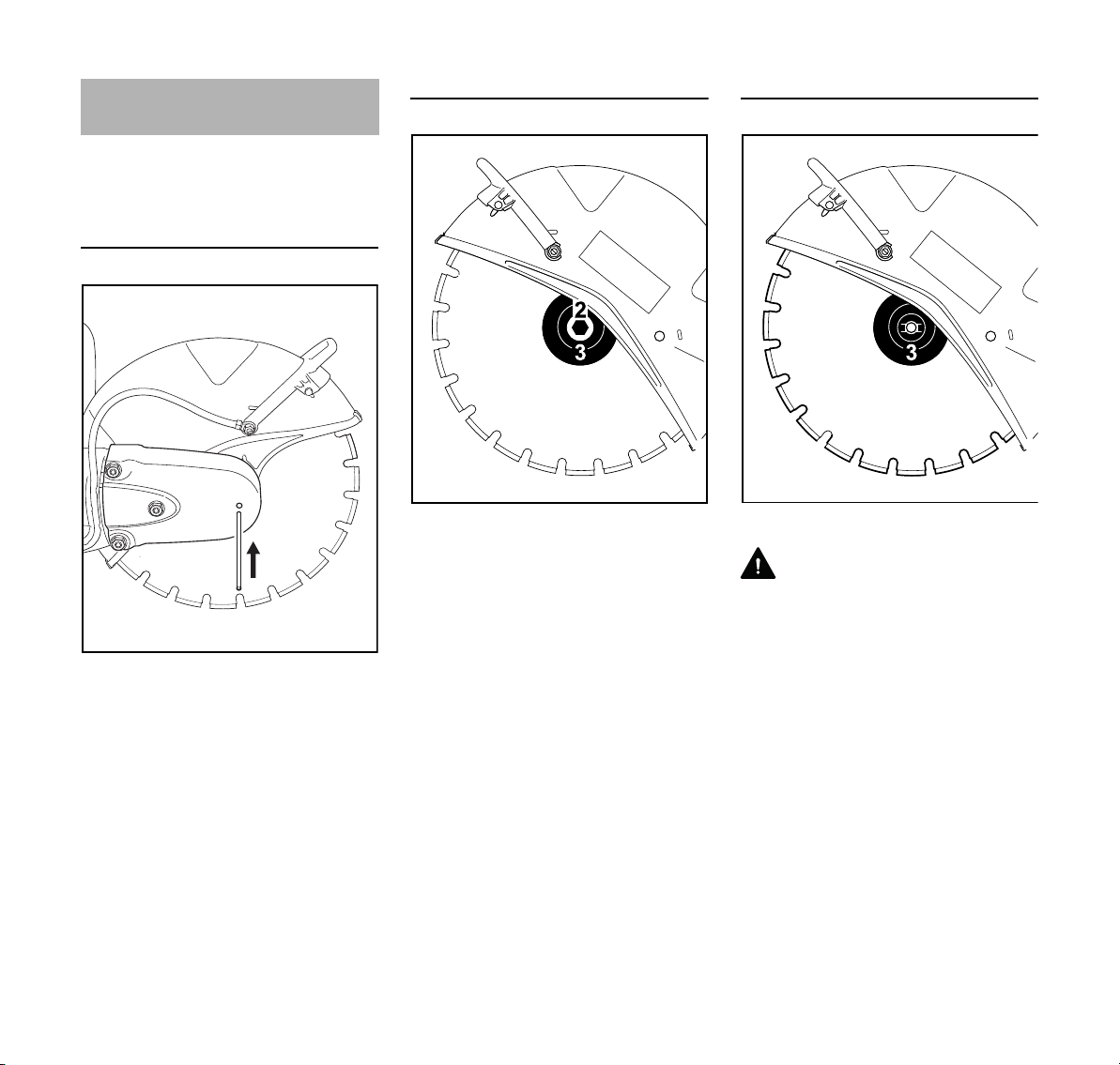
Blocking the shaft
1
N Slide the locking pin (1) through the
bore in the V-belt guard
N Turn the shaft with the combination
wrench until the locking pin (1)
engages in a bore behind the guard
Removing an abrasive wheel
N Use the combination wrench to
loosen and remove the hexagon
head screw (2)
N Remove the front thrust washer (3)
from the shaft together with the
377BA028 KN
abrasive wheel
Fitting an abrasive wheel
N Fit the new abrasive wheel (4)
WARNING
Note the arrows indicating the direction
of rotation on diamond abrasive wheels.
N Fit the front thrust washer (3). The
catches of the front thrust
washer (3) must engage in the shaft
grooves.
N Screw in the hexagon bolt and
tighten it with the combination
wrench – if using a torque wrench,
refer to the "Specifications" for the
tightening torque
N Draw the locking pin out of the V-
belt guard
TS 700, TS 800
25

English
WARNING
Never use two abrasive wheels at the
same time. The uneven wear creates a
risk of breaking and an injury hazard!
Fuel
This engine is certified to operate on
unleaded gasoline and with the mix ratio
50:1.
Your engine requires a mixture of highquality premium gasoline and highquality two-stroke air-cooled engine oil.
Use premium branded unleaded
gasoline with a minimum octane rating
of 89 (R+M)/2.
Note: Models equipped with a catalytic
converter require unleaded gasoline. A
few tankfuls of leaded gasoline can
reduce the efficiency of the catalytic
converter by more than 50%.
Fuel with a lower octane rating may
result in preignition (causing "pinging")
which is accompanied by an increase in
engine temperature. This, in turn,
increases the risk of the piston seizure
and damage to the engine.
The chemical composition of the fuel is
also important. Some fuel additives not
only detrimentally affect elastomers
(carburetor diaphragms, oil seals, fuel
lines etc.), but magnesium castings as
well. This could cause running problems
or even damage the engine. For this
reason it is essential that you use only
high-quality fuels!
Fuels with different percentages of
ethanol are being offered. Ethanol can
affect the running behaviour of the
engine and increase the risk of lean
seizure.
Gasoline with an ethanol content of
more than 10% can cause running
problems and major damage in engines
with a manually adjustable carburetor
and should not be used in such engines.
Engines equipped with M-Tronic can be
run on gasoline with an ethanol content
of up to 25% (E25).
Use only STIHL two-stroke engine oil or
equivalent high-quality two-stroke aircooled engine oils for mixing.
We recommend STIHL 50:1 two-stroke
engine oil since it is specially formulated
for use in STIHL engines.
To ensure the maximum performance of
your STIHL engine, use a high quality 2cycle engine oil. To help your engine run
cleaner and reduce harmful carbon
deposits, STIHL recommends using
STIHL HP Ultra 2-cycle engine oil or ask
your dealer for an equivalent fully
synthetic 2-cycle engine oil.
To meet the requirements of EPA and
CARB we recommend to use STIHL HP
Ultra oil.
Do not use BIA or TCW (two-stroke
water cooled) mix oils!
Use only STIHL 50:1 heavy-duty engine
oil or an equivalent quality two-stroke
engine oil for the fuel mix in models
equipped with a catalytic converter.
Take care when handling gasoline.
Avoid direct contact with the skin and
avoid inhaling fuel vapour.
The canister should be kept tightly
closed in order to avoid any moisture
getting into the mixture.
26
TS 700, TS 800
English
2.
1.
376BA102 KN
2.
1.
376BA103 KN
376BA104 KN
The fuel tank and the canister in which
fuel mix is stored should be cleaned
from time to time.
Fuel mix ratio
Only mix sufficient fuel for a few days
work, not to exceed 30 days of storage.
Store in approved safety fuel-canisters
only. When mixing, pour oil into the
canister first, and then add gasoline.
Examples
Gasoline Oil (STIHL 50:1 or equiva
-
lent high-quality oils)
liters liters (ml)
10.02(20)
5 0.10 (100)
10 0.20 (200)
15 0.30 (300)
20 0.40 (400)
25 0.50 (500)
Dispose of empty mixing-oil canisters
only at authorized disposal locations.
Fueling
Preparing the machine
N Before fueling, clean the filler cap
and the area around it so that dirt
cannot fall into the tank
N Always position the machine so that
the filler cap is facing upwards
WARNING
Never use a tool to open the bayonet
filler cap. The cap can be damaged and
fuel may escape.
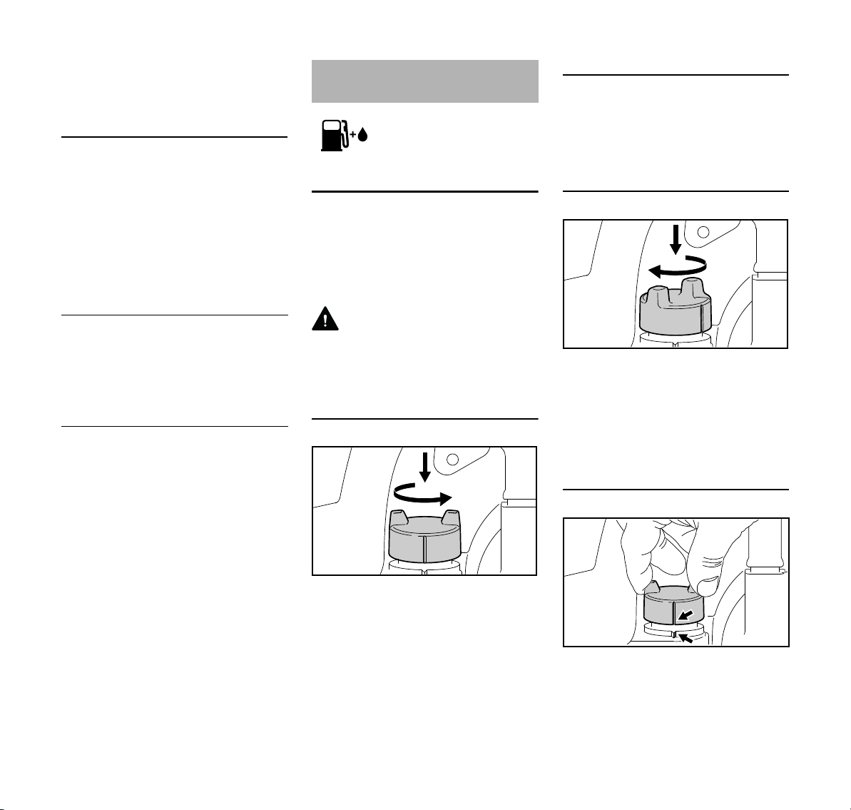
Opening the filler cap
Refueling
Take care not to spill fuel while fueling
and do not overfill the tank. STIHL
recommends use of the STIHL filling
system for fuel (special accessory).
Closing the filler cap
N Fit the cap and turn it until it
engages in the bayonet catch
N Press the cap down as far as
possible with your hand and turn it
clockwise (approx. 1/8 of a turn)
until it engages properly
TS 700, TS 800
Checking the lock
N Press the filler cap down as far as
possible by hand, then turn it
counterclockwise (approx. 1/8 turn)
and remove
N Grip the cap – the cap is closed
properly if it cannot be removed and
the markings (arrows) on the cap
and fuel tank are aligned
27
English
If the cap can be removed or the
markings do not align, close the cap
again – see sections "Closing the cap"
and "Checking the lock".
Changing the fuel pickup body every
year
N Drain the fuel tank
N Pull the fuel pickup body out of the
tank with a hook and disconnect it
from the hose
N Connect a new fuel pickup body to
the hose
N Return the fuel pickup body to the
tank
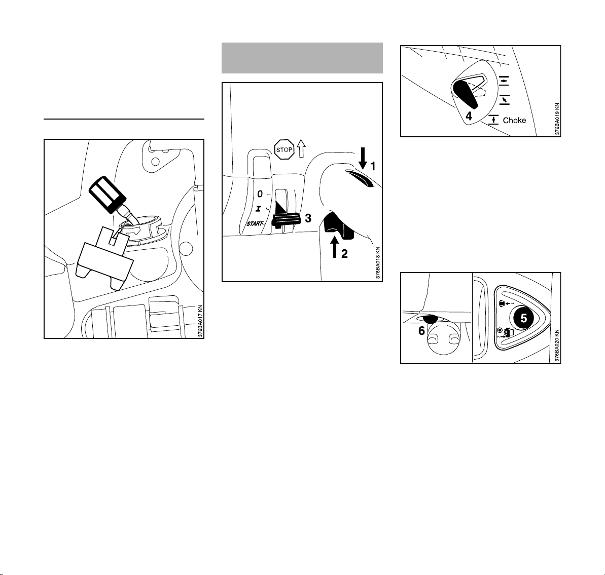
Starting / Stopping the
Engine
N Note the safety instructions. Refer
to the chapter headed "Safety
precautions and working
techniques".
N Press throttle trigger lockout (1) and
throttle trigger (2) simultaneously
N Hold both triggers down
N Move the master control lever (3) to
START and hold it in position too
N Release the throttle trigger, master
control lever and throttle trigger
lockout in succession = starting
throttle position
N Set the choke (4) according to the
engine temperature
c If engine is cold
e if the engine is warm (even if the
engine is already running but is still
cold or if the warm engine was shut
off for less than 5 min)
o if the engine is hot (if the hot engine
was switched off for longer than
5min)
N Press the button (5) of the
decompression valve before each
starting procedure
N Press the bulb (6) of the manual fuel
pump 7-10 times – even when the
bulb is still filled with fuel
28
TS 700, TS 800
 Loading...