

Stihl STIHL FSA 90 R STIHL FSA 90 R (en / fr) [en, fr]
STIHL FSA 90 R
Instruction Manual
Notice d’emploi

G Instruction Manual
1 - 31
F Notice d’emploi
32 - 65

Contents
English
Guide to Using this Manual 2
Safety Precautions 2
Reactive Forces 8
Working Techniques 8
Approved Combinations of Cutting
Attachment, Deflector, Handle and
Harness 10
Mounting the Loop Handle 11
Mounting the Deflector 12
Original Instruction ManualPrinted on chlorine-free paper
Mounting the Cutting Attachment 13
Connecting Charger to Power
Supply 15
Charging the Battery 16
LEDs on Battery 17
LED on Charger 18
Fitting the Harness 19
Balancing the Machine 19
Switching On 20
Switching Off 22
Storing the Machine 22
Maintaining the Mowing Head 23
Sharpening Metal Cutting Blades 24
Printing inks contain vegetable oils, paper can be recycled.
Maintenance and Care 25
Main Parts 26
Specifications 27
Troubleshooting 29
Maintenance and Repairs 31
Battery Recycling 31
Disposal 31
Dear Customer,
Thank you for choosing a quality
engineered STIHL product.
It has been built using modern
production techniques and
comprehensive quality assurance.
Every effort has been made to ensure
your satisfaction and trouble-free use of
the product.
Please contact your dealer or our sales
company if you have any queries
concerning this product.
Your
Dr. Nikolas Stihl
© ANDREAS STIHL AG & Co. KG, 2022
0458-709-8221-B. VA2.B22.
0000007009_009_GB
FSA 90 R
This instruction manual is protected by copyright. All rights reserved, especially the rights to reproduce, translate and process
with electronic systems.
1
English
Guide to Using this Manual
This instruction manual covers a
STIHL cordless trimmer which is also
referred to as the power tool or machine
in the descriptions.
Pictograms
The meanings of the pictograms
attached to the machine are explained in
this manual.
Depending on the model concerned, the
following pictograms may be attached to
your machine.
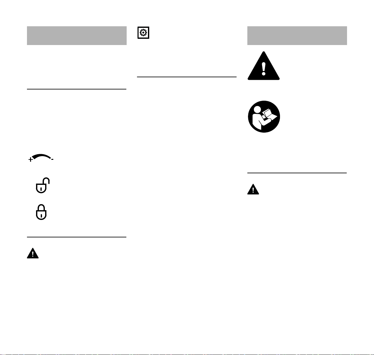
Preset trigger travel
(infinitely variable)
Unlock
Lock
Symbols in text
WARNING
Warning where there is a risk of an
accident or personal injury or serious
damage to property.
NOTICE
Caution where there is a risk of
damaging the machine or its individual
components.
Engineering improvements
STIHL's philosophy is to continually
improve all of its products. For this
reason we may modify the design,
engineering and appearance of our
products periodically.
Therefore, some changes, modifications
and improvements may not be covered
in this manual.
Safety Precautions
Some special safety precautions have to be
observed when working
with this power tool
because of the very high
speed of the cutting
attachment.
It is important that you
read the instruction manual before first use and
keep it in a safe place for
future reference. Nonobservance of the safety
precautions may result in
serious or even fatal
injury.
General
WARNING
– Minors should never be allowed to
operate this power tool. Watch
children to be sure that they do not
play with the power tool.
– This power tool may be operated
only by persons who have been
instructed in its use and proper
handling.
– This power tool may not be used by
persons who are not able to operate
it safely due to limited physical,
sensory or mental ability.
2
FSA 90 R
English
– Lend or rent your power tool only
together with this instruction manual
and only to persons who are familiar
with this model and its operation.
– Remove the battery before
performing any work on the power
tool, e.g. cleaning, maintenance,
replacing parts.
If you have not used this model before:
Have your dealer or a trained expert
show you how to operate it properly and
safely.
Observe all applicable local safety
regulations, standards and ordinances.
The use of noise emitting power tools
may be restricted to certain times by
national or local regulations.
Keep bystanders, especially children,
and animals away from the work area.
The user is responsible for avoiding
injury to third parties or damage to their
property.
To operate this power tool you must be
rested, in good physical condition and
mental health.
If you have any condition that might be
aggravated by strenuous work, check
with your doctor before operating a
power tool.
Do not operate the power tool if you are
under the influence of any substance
(drugs, alcohol) which might impair
vision, dexterity or judgment.
Remove the battery from
the power tool:
– before carrying out inspections,
adjustments or cleaning work
– before working on the cutting
attachment
– before leaving the machine
unattended
– before transporting
– before storing
– before performing repairs and
maintenance work
– in the event of danger or in an
emergency
This avoids the risk of the motor starting
unintentionally.
Intended Use
Use your power tool only as specified for
the cutting attachment mounted, see
"Working Techniques".
Do not use your power tool for any other
purpose – risk of accidents.
Never attempt to modify your power tool
in any way since this may increase the
risk of personal injury. STIHL excludes
all liability for personal injury and
damage to property caused while using
unauthorized attachments.
Clothing and Equipment
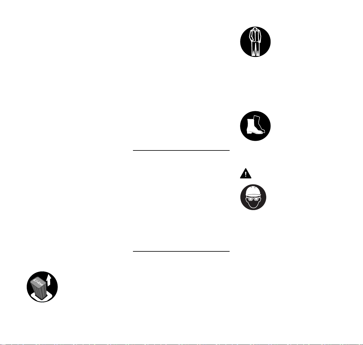
Wear proper protective clothing and
equipment.
Clothing must be sturdy
but allow complete freedom of movement. Wear
snug-fitting clothing, an
overall and jacket combination, do not wear a
work coat.
Avoid clothing that could get caught on
branches or brush or moving parts of the
machine. Do not wear a scarf, necktie or
jewelry. Tie up and confine long hair
(e.g. with a hair net, cap, hard hat, etc.).
Wear steel-toed safety
boots with non-slip soles.
Sturdy shoes with non-slip soles may be
worn as an alternative only when using
mowing heads.
WARNING
To reduce the risk of eye
injuries, wear close-fitting safety glasses in
accordance with European Standard EN 166.
Make sure the safety
glasses are a comfortable and snug fit.
Wear a face shield. A face shield alone
does not provide adequate eye
protection.
Wear a safety hard hat where there is a
danger of head injuries from falling
objects.
FSA 90 R
3
English
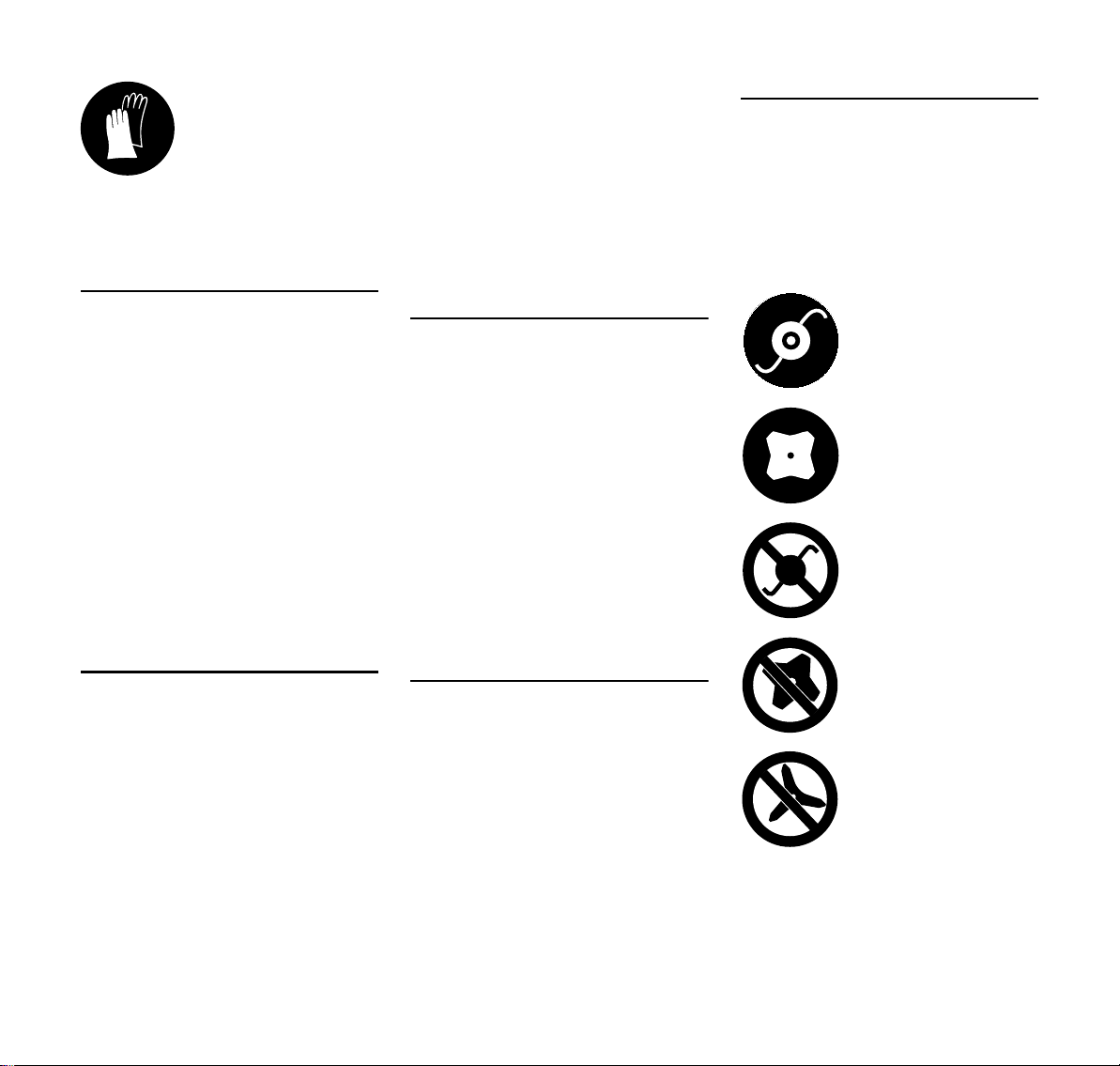
Wear heavy-duty work
gloves made of durable
material (e.g. leather).
STIHL offers a comprehensive range of
personal protective clothing and
equipment.
Transporting
Before transporting – even for short
distances – always switch off the
machine, move the retaining latch to ƒ
and remove the battery. This avoids the
risk of the motor starting unintentionally.
Carry the unit horizontally and properly
balanced by the drive tube.
To reduce the risk of cut injuries, fit
transport guard on a metal cutting
attachment, even when carrying the tool
for short distances.
Transporting by vehicle: Properly secure
the power tool to prevent turnover and
damage.
Cleaning
Clean plastic surfaces with a cloth. Do
not use aggressive detergents. They
may damage the plastic.
Always clean dust and dirt off the power
tool – do not use any grease solvents for
this purpose.
Clean the cooling slots if necessary.
Keep the battery guides free from
foreign matter – clean as necessary.
Do not use a pressure washer to clean
the unit. The solid jet of water may
damage parts of the unit.
Do not spray the power tool with water.
Do not spray the cutting attachment or
deflector with water or immerse them in
water as this may damage the drive
motor and electronic control unit in the
motor housing.
Accessories
Only use cutting attachments and
accessories that are explicitly approved
for this power tool by STIHL or are
technically identical. If you have any
questions in this respect, consult a
servicing dealer. Use only high quality
tools and accessories in order to avoid
the risk of accidents and damage to the
unit.
STIHL recommends the use of genuine
STIHL tools and accessories. They are
specifically designed to match the
product and meet your performance
requirements.
Drive
Battery
Follow the supplement sheet or User
Manual for the STIHL rechargeable
battery and keep them in a safe place.
For further safety instructions, see
www.stihl.com/safety-data-sheets
Battery charger
Observe the supplement sheet for the
STIHL charger and keep in a safe place.
Symbols on Deflectors
An arrow on the deflector shows the
correct direction of rotation of the cutting
attachments.
Some of the following symbols are
applied to the outside of the deflector to
indicate the approved combination of
cutting attachment and deflector.
Deflector may be used
with mowing heads.
Deflector may be used
with grass cutting blades.
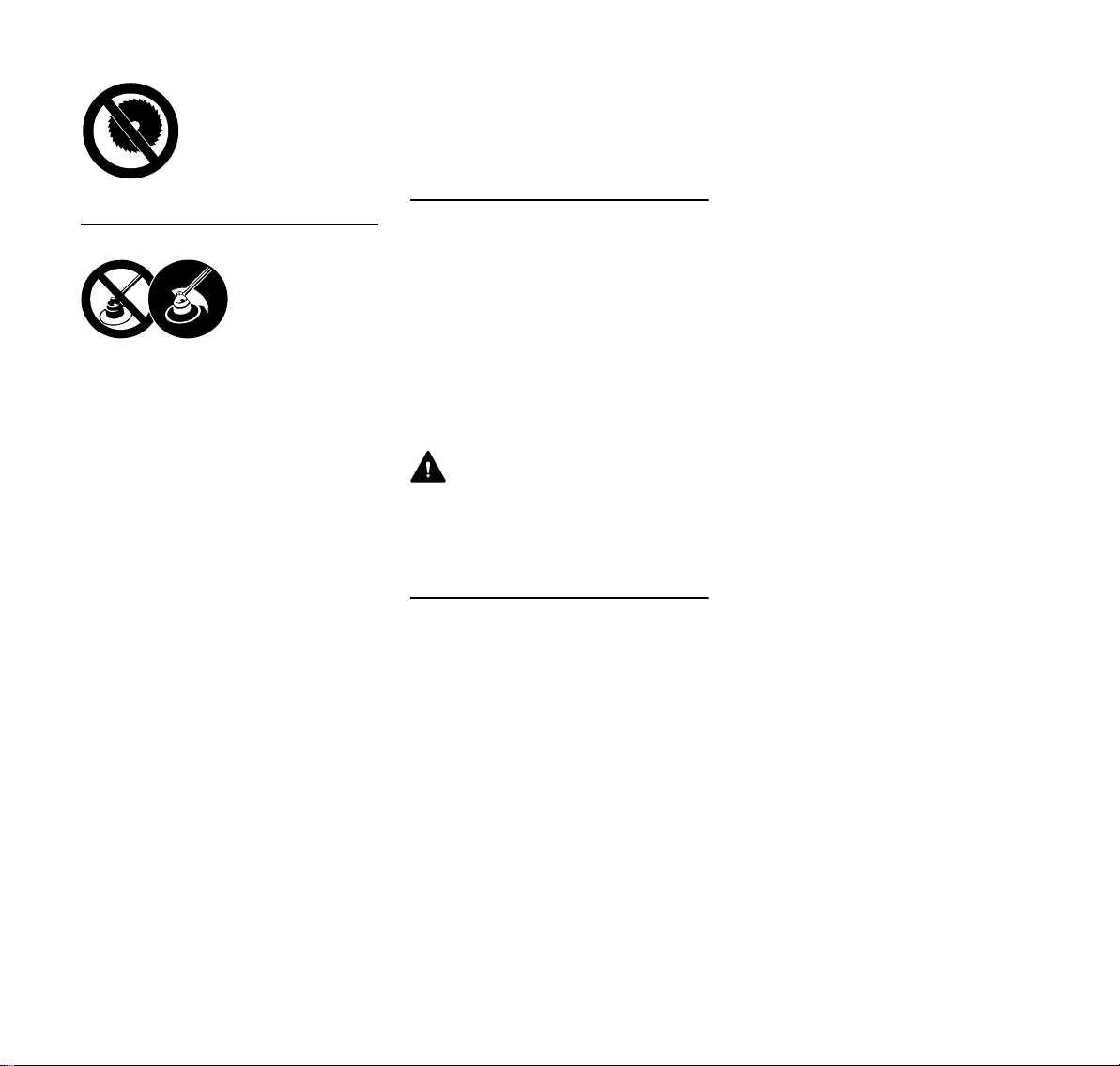
Deflector must not be
used with mowing heads.
Deflector must not be
used with grass cutting
blades.
Deflector must not be
used with brush knives.
4
FSA 90 R
English
Deflector must not be
used with circular saw
blades.
Cutting Attachments
To reduce the risk
of injury from
thrown objects,
never operate the
power tool without
the proper deflector for the type of
cutting attachment
being used.
The deflector on this power tool cannot
protect the operator from all objects
thrown by the cutting attachment
(stones, glass, wire, etc.). Such objects
may ricochet and then hit the operator.
Check the cutting attachment at regular
short intervals during operation or
immediately if there is a noticeable
change in cutting behavior:
– Switch off the motor, move the
retaining latch to ƒ and wait for the
cutting attachment to come to a
standstill, remove the battery.
– Check condition and tightness, look
for cracks.
To replace the cutting attachment,
switch off the power tool, move the
retaining latch to ƒ and remove the
battery. This avoids the risk of injury
from the motor starting unintentionally.
Never continue using or attempt to
repair damaged or cracked cutting
attachments.
This may cause parts of the cutting
attachment to come off and hit the
operator or bystanders at high speed
and result in serious or fatal injuries.
Using Mowing Heads
Use only the deflector with properly
mounted line limiting blade to ensure the
mowing lines are automatically trimmed
to the approved length.
Before adjusting nylon line on manually
adjustable mowing heads, switch off the
machine, set retaining latch to ƒ and
remove the battery. This avoids the risk
of injury from the motor starting
unintentionally.
WARNING
To reduce the risk of serious injury,
never use wire or metal-reinforced line in
place of the nylon line.
Using Metal Cutting Attachments
STIHL recommends the use of original
STIHL metal cutting attachments. They
are specifically designed to match your
model and meet your performance
requirements.
Metal cutting attachments rotate at very
high speed. The forces that occur act on
the machine, the attachment and the
material being cut.
Sharpen metal cutting attachments
regularly as specified.
Check sharpness. Replace or sharpen
dull metal cutting attachments
immediately.
Unevenly sharpened metal cutting
attachments cause out-of-balance
which can impose extremely high loads
on the machine and increase the risk of
breakage.
Dull or improperly sharpened cutting
edges can put a higher load on the metal
cutting attachment and increase the risk
of injury from cracked or broken parts.
Inspect metal cutting attachments for
cracks or warping after every contact
with hard objects (e.g. stones, rocks,
pieces of metal). To reduce the risk of
injury, remove burrs and other visible
build-ups of material (use a file) because
they may become detached and be
thrown at high speed during operation.
Do not continue using or attempt to
repair damaged or cracked metal cutting
attachments by welding, straightening or
modifying the shape (out of balance).
If a rotating metal cutting attachment
makes contact with a rock or other solid
object there is a risk of sparking which
may cause easily combustible material
to catch fire under certain
circumstances. Dry plants and scrub are
also easily combustible, especially in hot
and dry weather conditions. If there is a
risk of fire, do not use metal cutting
attachments near combustible
materials, dry plants or scrub. Always
contact your local forest authority for
information on a possible fire risk.
To reduce the above-mentioned risks
when using a metal cutting attachment,
never use a metal cutting attachment
with a diameter larger than specified. It
must not be too heavy. It must be
manufactured from materials of
adequate quality and its geometry must
be correct (shape, thickness).
FSA 90 R
5
English
15m (50ft)
To reduce the risk of injury, a metal
cutting attachment not manufactured by
STIHL must not be heavier, thicker,
have a different shape or a diameter
larger than the largest metal cutting
attachment approved by STIHL for this
power tool model.
Before Starting Work
Check that your power tool is properly
assembled and in good condition – refer
to appropriate chapters in the instruction
manual.
– The trigger and trigger lockout must
move freely and spring back to the
idle position when they are
released.
– Use only an approved combination
of cutting attachment, deflector and
handle. All parts must be
assembled properly and securely.
– Check that the cutting attachment is
properly and securely mounted and
in good condition.
– Check protective devices (e.g.
deflector for cutting attachment,
rider plate) for damage or wear.
Always replace damaged parts. Do
not operate your machine with a
damaged deflector or worn rider
plate (lettering and arrows no longer
legible).
– Never attempt to modify the controls
or safety devices in any way.
– Keep the handles dry and clean –
free from oil and dirt – for safe
control of the power tool.
– Check contacts in battery
compartment for foreign matter.
6
– Fit the battery correctly – it must
engage audibly.
– Never use defective or deformed
batteries.
To reduce the risk of accidents, do not
operate the unit if it is not properly
assembled and in good condition.
Switching On
Before switching on your power tool,
make sure the cutting attachment is not
touching the ground or any other object.
To reduce the risk of injury, avoid
contact with the cutting attachment.
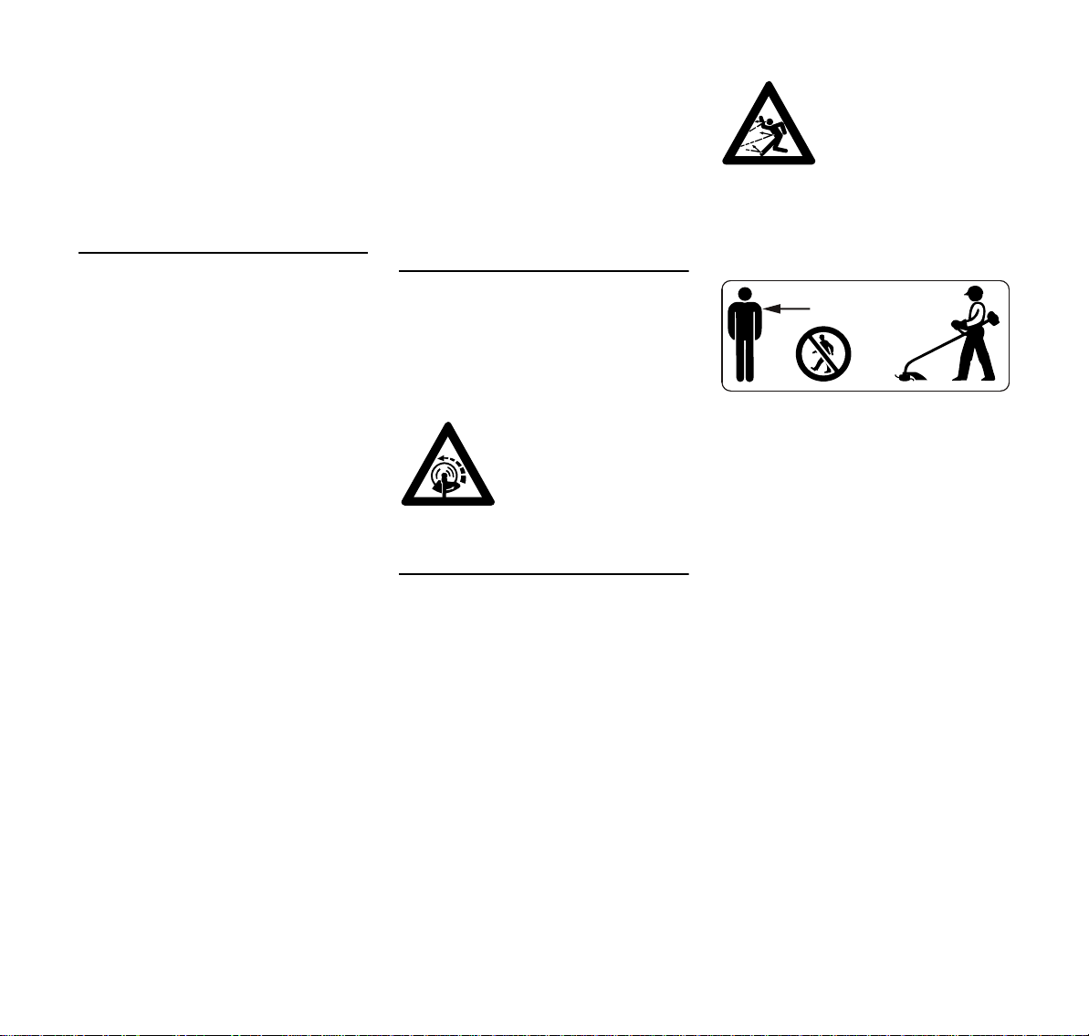
Note that the cutting
attachment continues to
run for a short period
after the power tool is
switched off – flywheel
effect.
During Operation
In case of imminent danger or in an
emergency, switch off the motor
immediately, move retaining latch to ƒ
and remove the battery.
This power tool may be used in the rain
and wet. Dry off your power tool after
finishing work.
Do not leave the power tool outdoors in
the rain.
Take special care in slippery conditions
(ice, wet ground, snow), on slopes or
uneven ground.
Watch out for obstacles: Roots and tree
stumps which could cause you to trip or
stumble.
Inspect the work area:
Stones, pieces of metal
or other solid objects may
be thrown more than 15
meters and cause personal injury or damage
the cutting attachment
and property (e.g. parked
vehicles, windows).
The cutting attachment may catch and
fling objects a great distance and cause
injury - therefore, do not allow any other
persons within a radius of 15 meters of
your own position. To reduce the risk of
damage to property, also maintain this
distance from other objects (vehicles,
windows). Even maintaining a distance
of 15 meters or more cannot exclude the
potential danger.
To reduce the risk of accidents, take a
break in good time to avoid tiredness or
exhaustion.
Work calmly and carefully – in daylight
conditions and only when visibility is
good. Stay alert so as not to endanger
others.
Special care must be taken when
working in difficult, over-grown terrain.
The dust that occurs during operation
may be harmful to health. If dust levels
are very high, wear a suitable respirator.
FSA 90 R

English
0208BA006 KN
Clean grass and plant residue off the
cutting attachment mounting at regular
intervals – remove any build up of
material from the cutting attachment and
deflector.
Before leaving the power tool
unattended: Always switch off the power
tool, set the retaining latch to ƒ and
remove the battery.
If your power tool is subjected to
unusually high loads for which it was not
designed (e.g. heavy impact or a fall),
always check that it is in good condition
before continuing work – see also
"Before Starting Work". Make sure the
safety devices are working properly. Do
not continue operating your power tool if
it is damaged. In case of doubt, consult
your servicing dealer.
Always hold the power tool firmly with
both hands on the handles.
Make sure you always have good
balance and secure footing.
Models with loop handle
Right hand on control handle, left hand
on loop handle, even if you are lefthanded.
After Finishing Work
Switch off the power tool, move retaining
latch to ƒ and remove the battery.
Storing
When the power tool is not in use, store
it so that it does not endanger others.
Secure it against unauthorized use.
Store the machine in a dry, locked
location with the retaining latch on ƒ
and the battery removed.
Vibrations
This power tool minimizes the vibrations
transmitted to the operator's hands.
However, the operator should seek
medical advice in the event of suspected
circulatory problems in the hands (e.g.
tingling sensation in the fingers).
Maintenance and Repairs
Always move the retaining latch to ƒ
and remove the battery before carrying
out any repairs or maintenance work on
the power tool. This avoids the risk of the
motor starting unintentionally.
Service the machine regularly. Do not
attempt any maintenance or repair work
not described in the instruction manual.
Have all other work performed by a
servicing dealer.
STIHL recommends that you have
servicing and repair work carried out
exclusively by an authorized STIHL
servicing dealer. STIHL dealers are
regularly given the opportunity to attend
training courses and are supplied with
the necessary technical information.
Only use high-quality replacement parts
in order to avoid the risk of accidents
and damage to the unit. If you have any
questions in this respect, consult a
servicing dealer.
STIHL recommends the use of genuine
STIHL replacement parts. They are
specifically designed to match your
model and meet your performance
requirements.
Never attempt to modify your power tool
in any way since this will increase the
risk of personal injury.
Check the electrical contacts and ensure
that the insulation of the connecting
cords and plug of the charger show no
sign of aging (brittleness).
Electrical components, e.g. connecting
cord of charger, may only be repaired or
replaced by a qualified electrician.
Check tightness of mounting screws on
safety devices and the cutting
attachment and retighten if necessary.
FSA 90 R
7
English
002BA135 KN
1
3988BA000 KN
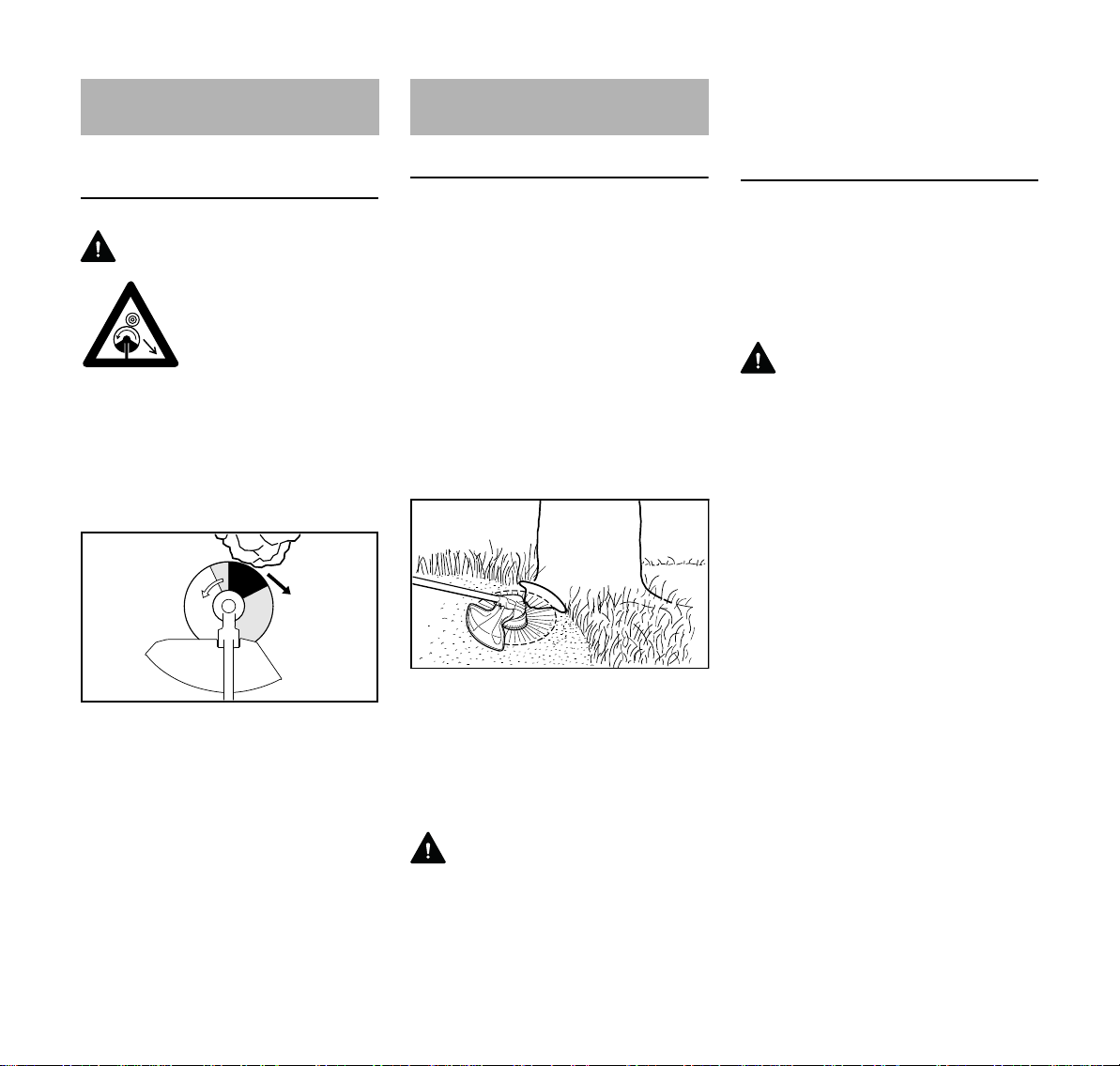
Reactive Forces
Risk of Kickout (Blade Thrust) with Metal
Cutting Attachments
WARNING
When using metal cutting attachments there is
a risk of kickout when the
rotating blade comes into
contact with a solid object
such as a tree trunk,
branch, tree stump, rock
or similar. The machine is
thrown to the right or to
the rear – opposite to the
attachment's direction of
rotation.
Working Techniques
Mowing Head with Nylon Line
Nylon line mowing heads are suitable for
lawn edging and trimming small to
medium areas and around obstacles.
The working technique is described
below, see "Mowing".
The mowing head comes with an
instruction leaflet. Refill the mowing
head with nylon line as described in the
instruction leaflet.
Working with Bump Guard
The bump guard is available as a special
accessory.
come to a standstill before adjusting the
bump guard – do not adjust it with your
foot.
Grass Cutting Blade
Grass cutting blades are suitable for
cutting tough grass, weeds. fern,
stinging nettles and reed. They are
robust and can be used for mowing large
areas. The working technique is
described below, see "Mowing".
WARNING
Improper use may damage the grass
cutting blade – risk of injury from thrown
parts.
Resharpen the grass cutting blade
according to instructions when it has
dulled noticeably.
The risk of kickout is greatest when the
black area of the rotating cutting
attachment comes into contact with a
solid object.
8
The bump guard (1)
– limits the cutting range of the
mowing line
– reduces the risk of the rotating
mowing line causing damage (e.g.
tree bark)
WARNING
The mowing head may continue to
rotate briefly after you switch off your
power tool – wait for the mowing head to
FSA 90 R
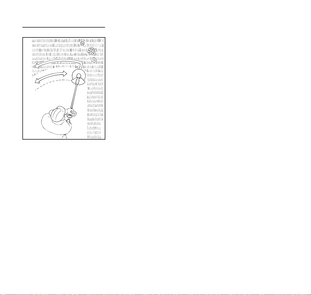
Mowing
002BA341 KN
N Hold your trimmer with both hands –
right hand on the control handle.
N Stand upright – hold the power tool
in a relaxed position.
N Make sure the cutting attachment is
not touching the ground or any other
objects.
N Swing the trimmer back and forth in
an arc.
N The cutting height is determined by
the distance of the mowing line from
the lawn surface.
N Avoid contact with fences, walls,
rocks, etc. since it will result in a
higher rate of wear.
Do not throw cuttings in the garbage
can. They can be composted.
English
FSA 90 R
9
English
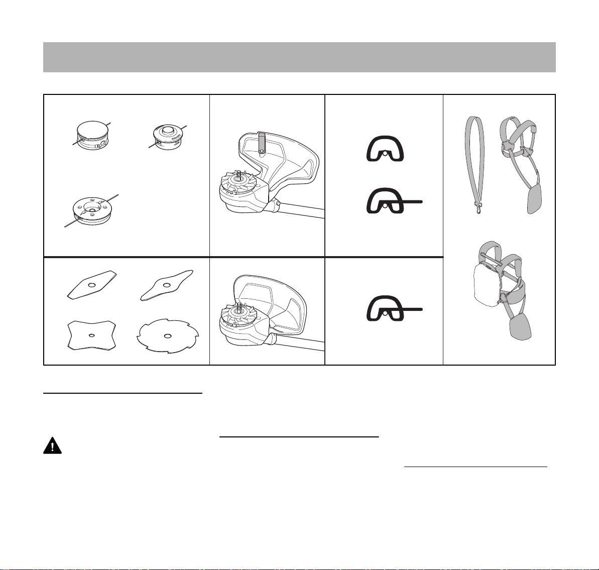
Approved Combinations of Cutting Attachment, Deflector, Handle and Harness
Cutting attachment Deflector Handle Carrying strap
1
2
3
4
6
Permissible combinations
Choose the correct combination from
the table depending on the cutting tool!
WARNING
For safety reasons only the cutting
attachments, deflector, handle and
harness versions within one line of the
table may be combined with one
5
7
8
9
another. No other combinations are
permitted because of the risk of
accidents.
Cutting attachments
Mowing heads
1 STIHL SuperCut 20-2
2 STIHL AutoCut 25-2
3 STIHL DuroCut 20-2
1)
1)
1)
10
11
11
13
14
12
15
12
16
Metal cutting tools
4 Grass cutting blade 230-2
(230 mm dia.)
1)
Operate the mowing head only with
2.4 mm diameter (0.095 in) round,
quiet mowing line
0000-GXX-0408-A1
10
FSA 90 R
English
3988BA034 KN
2
1
1
3988BA030 KN
2
5
4
3
6
7
3988BA007 KN
5 Grass cutting blade 260-2
(260 mm dia.)
6 Grass cutting blade 230-4
(230 mm dia.)
7 Grass cutting blade 230-8
(230 mm dia.)
WARNING
Grass cutting blades of materials other
than metal must not be used.
Deflectors
8 Deflector with line limiting blade
9 Deflector without line limiting blade
Handles
10 Loop handle
11 Loop handle with
12 Barrier bar
Shoulder straps
13 Shoulder strap can be used
14 Full harness can be used
15 Harness for Type AR battery may
be used together with
16 padding (special accessory)
See chapter "Fitting the Harness"
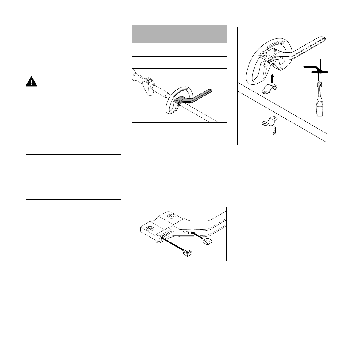
Mounting the Loop Handle
Using the Barrier Bar
A barrier bar may have to be mounted to
suit the cutting attachment you intend to
use – see "Approved Combinations of
Cutting Attachment, Deflector, Handle
and Harness".
The barrier bar comes standard with the
machine or is available as a special
accessory.
Mounting Loop Handle with Barrier Bar
N Place the clamp (3) in the loop
handle (4) and position them both
against the shaft (5).
N Position the clamp (6) against the
shaft.
N Place the barrier bar (2) in position
as shown.
N Line up the holes.
N Insert the screws (7) in the holes
and screw them into the barrier
bar (2) as far as stop.
N Go to "Adjusting and Securing the
Loop Handle".
FSA 90 R
N Fit the square nuts (1) in the barrier
bar (2); the holes must line up.
11
English
7
8
5
4
1
6
1
3
8
7
3988BA001 KN
4
A
3988BA029 KN
1
3988BA008 KN
2
3988BA009 KN
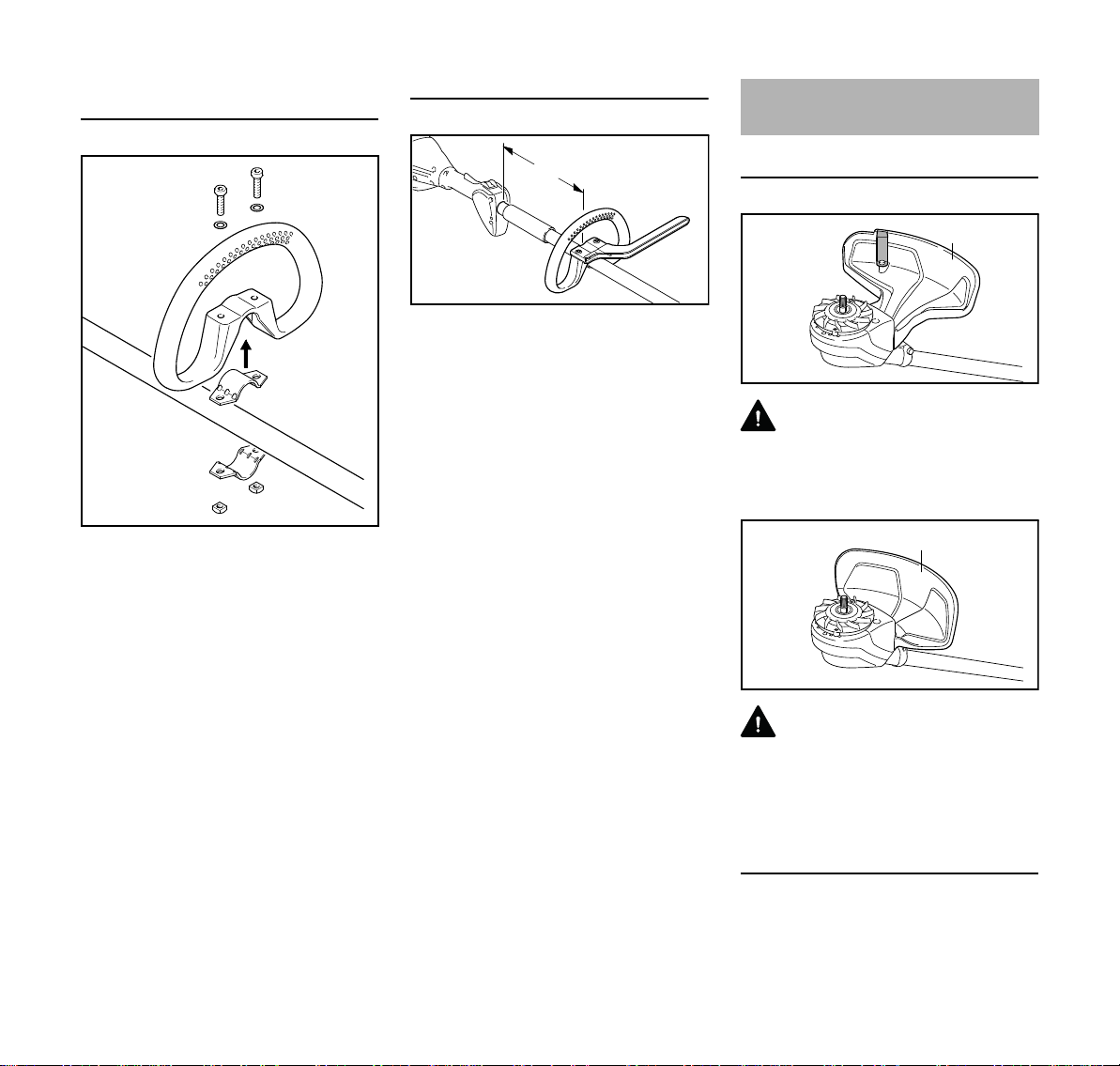
Mounting the Loop Handle without
Barrier Bar
N Place the clamp (3) in the loop
handle (4) and position them both
against the shaft (5).
N Position the clamp (6) against the
shaft.
N Line up the holes.
N Fit washers (8) on the screws (7)
and insert the screws in the holes.
Fit the square nuts (1) and screw
them down as far as stop.
N Go to "Adjusting and Securing the
Loop Handle".
Adjusting and Securing the Loop Handle
The loop handle can be adjusted to suit
the height and reach of the operator and
the application by changing
distance (A).
Distance A when using mowing heads:
Max. 30 cm (12 in)
Distance A when using metal cutting
attachments: Max. 25 cm (10 in)
N Slide the handle to the required
position.
N Line up the loop handle (4).
N Tighten down the screws until the
loop handle can no longer be
rotated on the shaft. If no barrier bar
is fitted – lock the nuts if necessary.
Mounting the Deflector
Use the Right Deflector
WARNING
Deflector (1) is approved for mowing
heads only and must therefore be
mounted before fitting a mowing head
WARNING
Deflector (2) is approved for grass
cutting blades only and must therefore
be mounted before fitting a grass cutting
blade.
12
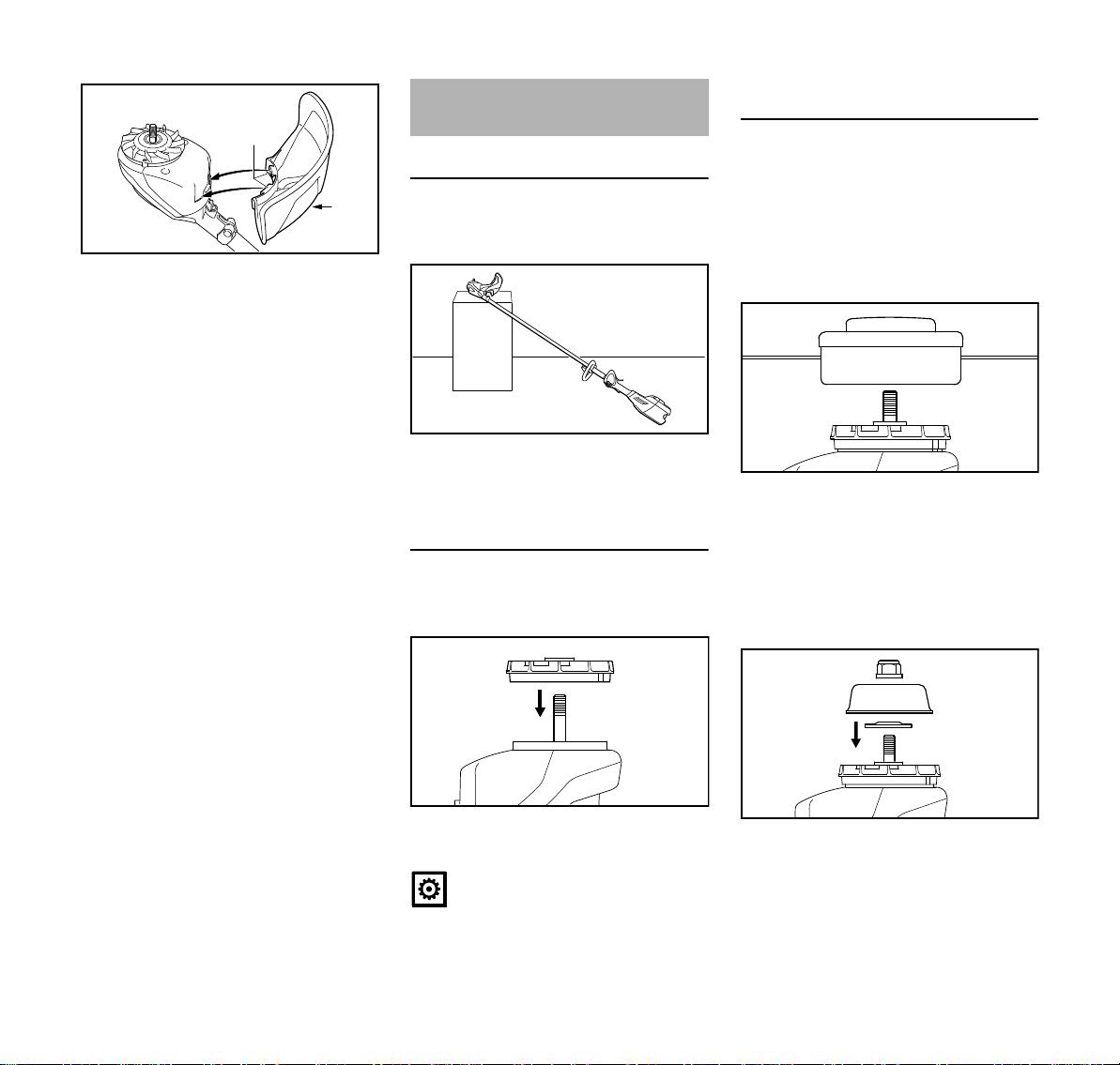
Mounting the Deflector
Deflectors (1 and 2) are both mounted to
the motor housing in the same way.
FSA 90 R
English
3
3988BA010 KN
4
3988BA028 KN
2
3988BA011 KN
1
2
3988BA012 KN
3
5
3988BA013 KN
4
N Position the deflector against the
motor housing.
N Push hooks (3) on deflector into the
recesses in the motor housing.
N Insert the screw (4) and tighten it
down firmly.
Mounting the Cutting
Attachment
Placing Power Tool on the Ground
N Move the retaining latch to ƒ and
remove the battery.
N Position your power tool so that the
cutting attachment mounting face is
pointing up.
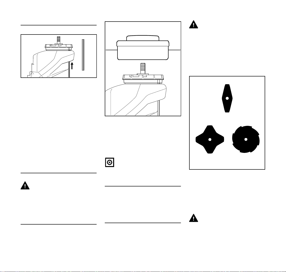
Mounting the Fanwheel
The machine comes standard with a
fanwheel.
Mounting Hardware for Cutting
Attachments
The mounting hardware supplied
depends on the cutting attachment that
comes as original equipment with the
new machine.
Machine supplied without mounting
hardware
Only mowing heads may be used which
mount directly to the shaft (2).
Machine supplied with mounting
hardware
Mowing heads and metal cutting
attachments may be mounted.
FSA 90 R
N Push the fanwheel (1) onto the
shaft (2).
NOTICE
The fanwheel is necessary for mounting
cutting attachments.
Depending on the cutting attachment, it
may be necessary to use the nut (3),
rider plate (4) and thrust washer (5).
These parts are included in a kit
supplied with the machine and are also
available as special accessories.
13
English
7
6
2
3988BA014 KN
6
2
3988BA015 KN
1
3
2
681BA050 KN
Blocking the Shaft
The output shaft (2) must be blocked
with the stop pin (6) to mount or remove
cutting attachments. The stop pin is
included with the machine and is
available as a special accessory.
N Push the stop pin (6) into the
hole (7) in the motor housing.
N Rotate the shaft, nut or cutting
attachment to line up the hole in the
fanwheel (1) with the stop pin (6).
N Push the stop pin (6) home until its
end is level with the blades on the
fanwheel (1).
The shaft is now blocked.
Mounting the Cutting Attachment
WARNING
Use a deflector that matches the cutting
attachment – see "Mounting the
Deflector".
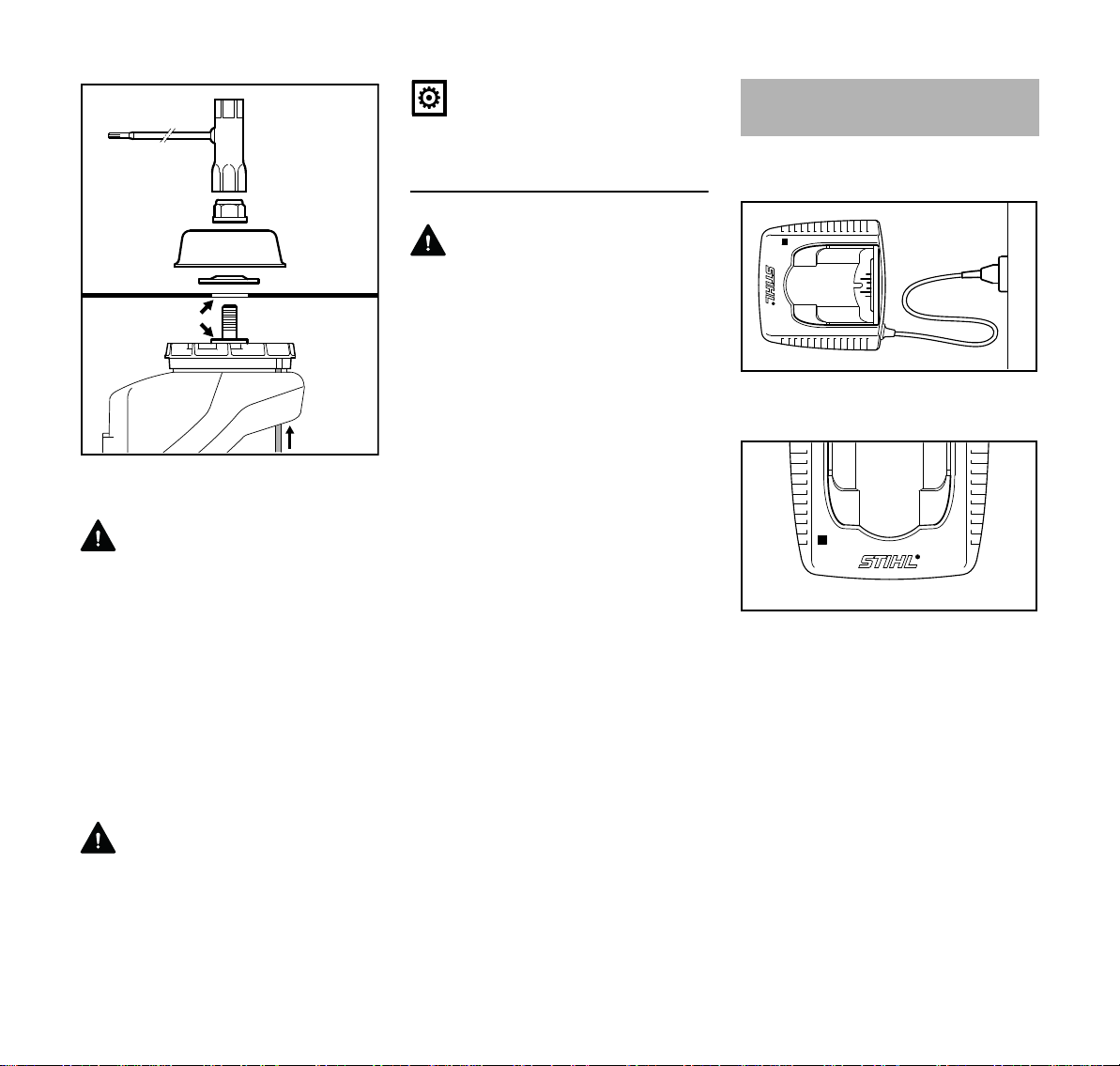
Fitting Mowing Head with Screw
Mounting
Keep the instruction leaflet for the
mowing head in a safe place.
N Screw the mowing head
counterclockwise on to the shaft (2)
as far as stop.
N Blocking the shaft
N Tighten down the mowing head
firmly.
NOTICE
Remove the tool used to block the shaft.
Remove the mowing head.
N Block the shaft.
N Unscrew the mowing head
clockwise.
Mounting the Metal Cutting Attachment
Keep the leaflet and packaging of the
metal cutting attachment in a safe place.
WARNING
Wear protective gloves to reduce the
risk of direct contact with the sharp
cutting edges.
Mount only one metal cutting
attachment.
Check direction of rotation of cutting
attachment
The cutting edges of the grass cutting
blades (1) and (2) may point in either
direction – these cutting attachments
must be turned over regularly to reduce
one-sided wear.
Cutting edges of grass cutting blade (3)
must point clockwise.
WARNING
Direction of rotation is indicated by an
arrow on the inside of the deflector.
14
FSA 90 R
English
6
4
5
7
8
9
3988BA016 KN
3901BA015 KN
2
1
1
3901BA019 KN
N Place the cutting attachment (4) on
the fanwheel (5).
WARNING
Collar (see arrow) must engage the
cutting attachment's mounting hole.
Securing the cutting attachment
N Fit the thrust washer (6) – convex
side must face up.
N Fit the rider plate (7).
N Block the shaft (8).
N Screw the mounting nut (9) on to the
shaft counterclockwise and tighten
it down firmly.
WARNING
If the mounting nut has become too
loose, fit a new one.
FSA 90 R
NOTICE
Remove the tool used to block the shaft.
Removing the Metal Cutting Attachment
WARNING
Wear protective gloves to reduce the
risk of direct contact with the sharp
cutting edges.
N Block the shaft.
N Unscrew the mounting nut
clockwise.
N Take the cutting attachment and its
mounting hardware off the
fanwheel (5) – but do not remove
the fanwheel.
Connecting Charger to
Power Supply
Power supply (mains) voltage and
operating voltage must be the same.
N Insert the plug (1) in the wall
outlet (2).
A self test is performed after the charger
is connected to the power supply. During
this process, the light emitting diode (1)
on the charger lights up green for about
1 second, then red and goes off again.
15
English
2
3901BA009 KN
4
3901BA014 KN
3
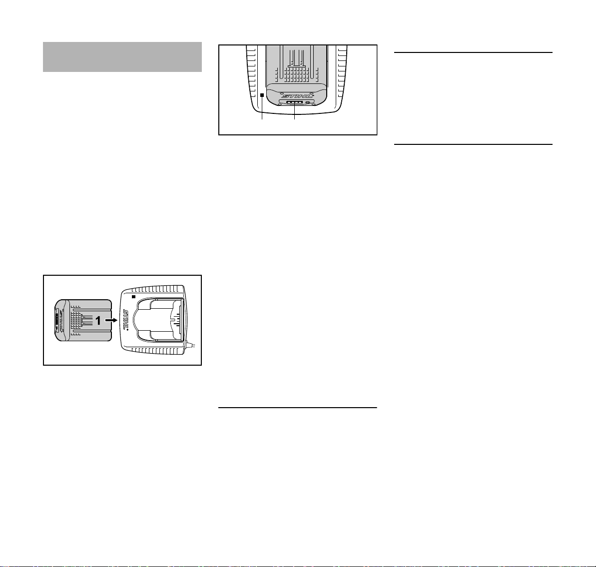
Charging the Battery
A factory-new battery is not fully
charged.
Recommendation: Fully charge the
battery before using it for the first time.
N Connect the charger to the power
supply – mains voltage and
operating voltage of the charger
must be the same – see
"Connecting Charger to Power
Supply".
Operate the charger only in enclosed
and dry rooms at ambient temperatures
between +5°C to +40°C (+41°F to
+104°F)
Only charge dry batteries. Allow a damp
battery to dry before charging.
N Push the battery (1) into the
charger (2) until noticeable
resistance is felt – then push it as far
as stop.
The LED (3) on the charger comes on
when the battery is inserted – see "LED
on Charger"
Charging begins as soon as the
LEDs (4) on the battery glow green –
see "LEDs on Battery".
The charge time is dependent on a
number of factors, including battery
condition, ambient temperature, etc.,
and may therefore vary from the times
specified.
The battery heats up during operation in
the power tool. If a hot battery is inserted
in the charger, it may be necessary to
cool it down before charging. The
charging process begins only after the
battery has cooled down. The time
required for cooling may prolong the
charge time.
The battery and charger heat up during
the charging process.
AL 300, AL 500 Chargers
AL 100 Charger
The AL 100 charger has no fan and
waits for the battery to cool down before
starting the charging process. The
battery is cooled by heat transfer to the
ambient air.
End of Charge
The charger switches itself off
automatically when the battery is fully
charged:
– LEDs on the battery go off.
– The LED on the charger goes off.
– The charger's fan is switched off (if
charger is so equipped)
Remove the fully charged battery from
the charger.
The AL 300 and AL 500 chargers are
equipped with a battery cooling fan
16
FSA 90 R

English
1
3901BA010 KN
3901BA018 KN
80 - 100 %
60 - 80 %
40 - 60 %
20 - 40 %
0 - 20 %
1
3901BA010 KN
3901BA016 KN
80 - 100 %
60 - 80 %
40 - 60 %
20 - 40 %
0 - 20 %
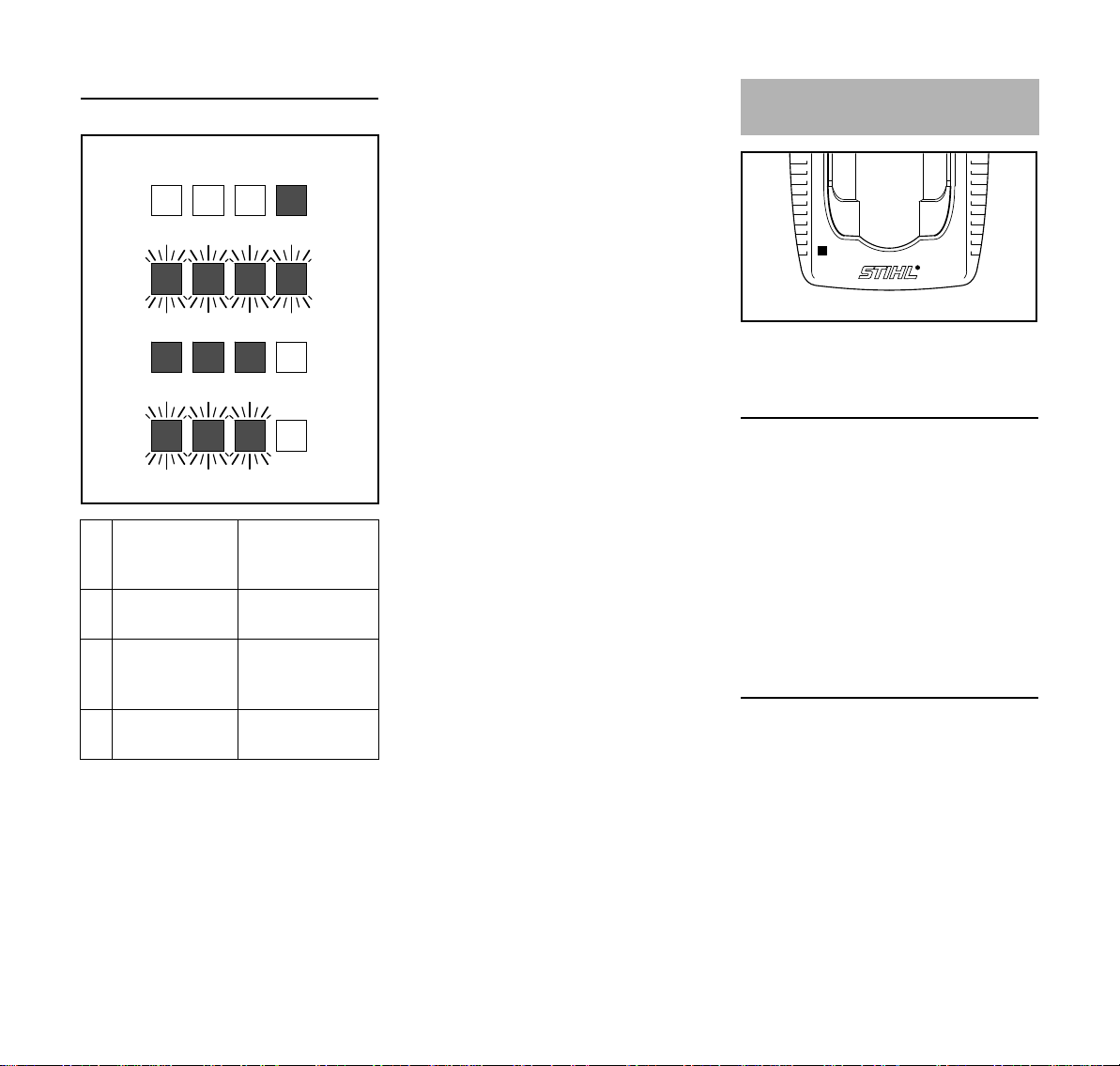
LEDs on Battery
Four LEDs show the battery's state of
charge and any problems that occur in
the battery or machine.
N Press button (1) to activate the
The LEDs can glow or flash green or
red.
display – the display goes off
automatically after 5 seconds.
LED glows continuously green.
LED flashes green.
LED glows continuously red.
LED flashes red.
During charging
The LEDs glow continuously or flash to
indicate the progress of charge.
A green flashing LED indicates the
capacity that is currently being charged.
The LEDs on the battery go off
automatically when the charge process
is completed.
If the LEDs on the battery flash or glow
red – see "If the red LEDs glow
continuously / flash".
During Operation
N Press button (1) to activate the
display – the display goes off
automatically after 5 seconds.
The green LEDs glow continuously or
flash to indicate the state of charge.
FSA 90 R
If the LEDs on the battery flash or glow
red – see "If the red LEDs glow
continuously / flash".
17
English
3901BA041 KN
A
B
C
D
1
3901BA019 KN
If the red LEDs glow continuously / flash
A 1 LED glows
continuously
Battery is too hot
1) 2)
/cold
red:
B 4 LEDs flash
C 3 LEDs glow
D 3 LEDs flash
1)
red
continuously
red:
red
When charging: Charge process
Malfunction in
battery
Machine is too hot
– allow it to cool
down.
Malfunction in
machine
starts automatically after the battery
has cooled down / warmed up.
2)
During operation: Machine cuts out
– allow battery to cool down; it may
be necessary to take the battery out
of the machine for this purpose.
3)
Electromagnetic problem or fault.
Take the battery out of the machine
LED on Charger
tool and refit it. Switch on the
machine – if the LEDs continue to
flash, the battery is faulty and must
be replaced.
4)
Electromagnetic problem or fault.
Take the battery out of the
machine. Use a blunt tool to
remove dirt from the contacts in the
battery compartment. Refit the
battery. Switch on the machine – if
the light emitting diodes still flash,
the machine is faulty and must be
checked by a servicing dealer –
STIHL recommends an authorized
STIHL servicing dealer.
The LED (1) on the charger may glow
continuously green or flash red.
Green continuous light ...
... indicates the following:
The battery
1)
– is being charged
– is too hot and must cool down
before charging
See also "LEDs on battery".
3)
The green LED on the charger goes off
as soon as the battery is fully charged.
Red flashing light ...
4)
... may indicate the following:
– No electrical contact between
battery and charger – remove and
refit the battery
– Malfunction in battery – see also
"LEDs on Battery".
– Malfunction in charger – have
checked by a servicing dealer.
STIHL recommends an authorized
STIHL servicing dealer.
18
FSA 90 R
English
1
3988BA017 KN
2
1
2
1
2
002BA387 KN
3988BA019 KN
Fitting the Harness
The type and style of the
harness/shoulder strap depend on the
market.
The use of the shoulder strap/harness is
described in the chapter on "Approved
Combinations of Cutting Attachment,
Deflector, Handle and Harness".
Use Type AR batteries only with the
harness provided – do not combine with
other carrying straps (e.g. shoulder
strap, full harness, etc.).
Shoulder Strap
N Put on the shoulder strap (1).
N Adjust the length of the strap so that
the carabiner (2) is about a hand’s
width below your right hip.
N Balance the machine – see
"Balancing the Machine".
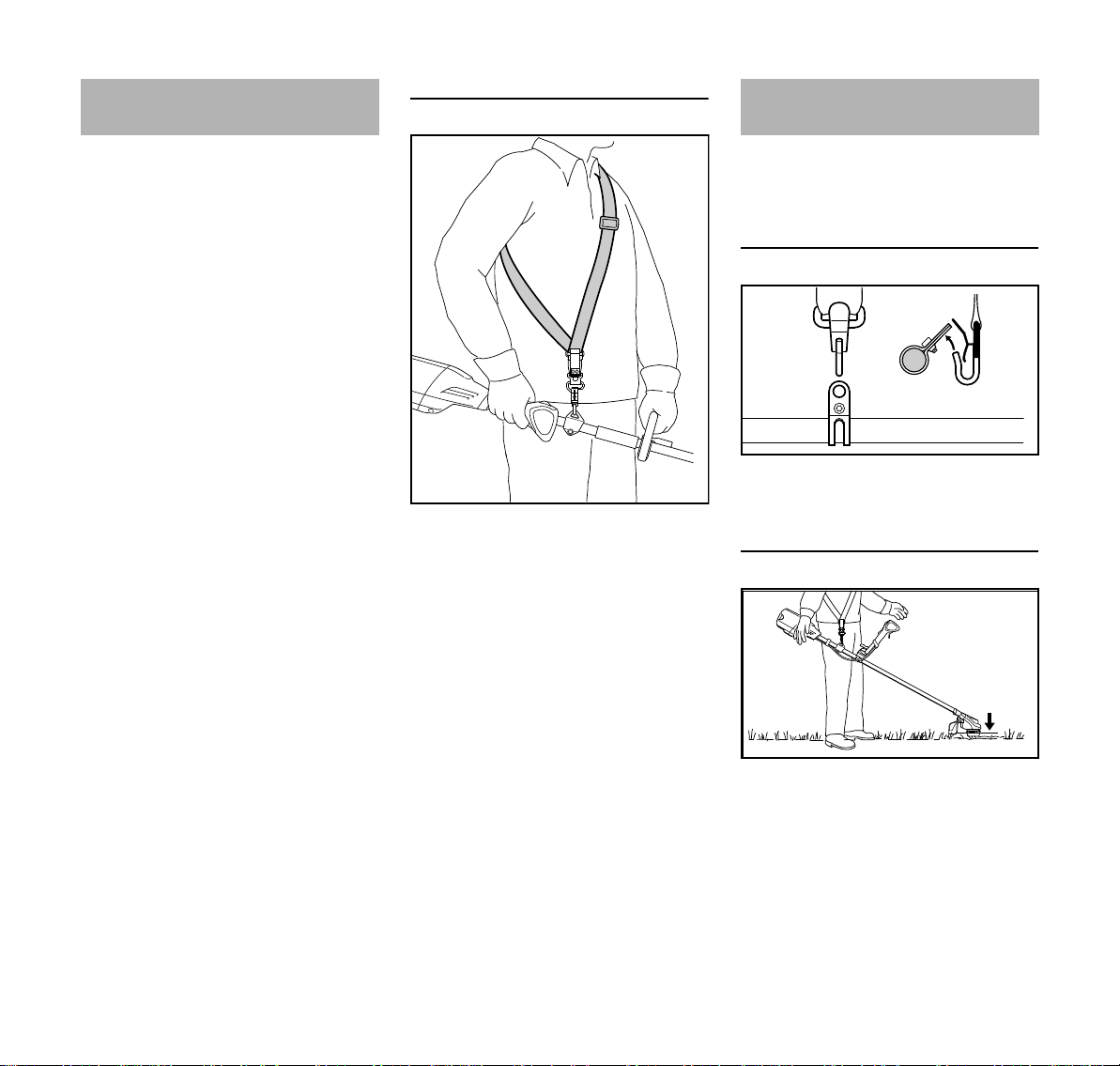
Balancing the Machine
The type and style of the harness and
carabiner (spring hook) depend on the
market.
Attaching Machine to Harness
N Attach the carabiner (1) to the
carrying ring (2) on the shaft.
Floating Position
FSA 90 R
N The cutting attachment should just
touch the ground.
The correct floating position is obtained
as follows:
19
 Loading...