

Page 1

{
STIHL MS 381
Manual de instrucciones
Instruction Manual
Page 2

E Manual de instrucciones
1 - 51
G Instruction Manual
52 - 100
Page 3

Original de Instrucciones de
servicio
Impreso en papel blanqueado sin cloro.
Los colores de la impresión contienen aceites vegetales, por lo
que el papel es reciclable.
© ANDREAS STIHL AG & Co. KG, 2013
0458-538-8721-A. VA5.L13.
0000000852_013_E
MS 381
español
1
{
Este manual de instrucciones está protegido por derechos de autor. Nos reservamos todos los derechos, especialmente el
derecho a la reproducción, traducción y elaboración con sistemas electrónicos.
Índice
Distinguidos clientes:
Muchas gracias por haber depositado
su confianza en un producto de calidad
de la empresa STIHL.
Este producto se ha confeccionado con
modernos procedimientos de
fabricación y amplias medidas para
afianzar la calidad. Procuramos hacer
todo lo posible para que usted esté
satisfecho con este producto y pueda
trabajar con él sin problemas.
En el caso de que tenga usted alguna
pregunta sobre este producto, diríjase a
su distribuidor STIHL o directamente a
nuestra empresa de distribución.
Atentamente
Dr. Nikolas Stihl
Notas relativas a este manual de
instrucciones 2
Indicaciones relativas a la
seguridad 3
Fuerzas de reacción 8
Técnica de trabajo 10
Equipo de corte 19
Montar la espada y la cadena 20
Tensar la cadena 21
Comprobar la tensión de la cadena 21
Combustible 21
Repostar combustible 23
Aceite lubricante de cadena 26
Repostar aceite de lubricación para
la cadena 27
Comprobar la lubricación de la
cadena 27
Freno de cadena 28
Arrancar / parar el motor 29
Indicaciones para el servicio 32
Ajustar el caudal de aceite 33
Mantenimiento de la espada 33
Limpiar el filtro de aire 34
Ajustar el carburador 35
Bujía 36
Rejilla parachispas en el
silenciador 38
Dispositivo de arranque 38
Guardar la máquina 38
Comprobar y cambiar el piñón de
cadena 39
Cuidados y afilado de la cadena 40
Instrucciones de mantenimiento y
conservación 44
Minimizar el desgaste y evitar
daños 46
Componentes importantes 47
Datos técnicos 48
Accesorios especiales 49
Adquisición de piezas de repuesto 49
Indicaciones para la reparación 50
Gestión de residuos 50
Declaración de conformidad CE 50
Page 4

MS 381
español
2
Este manual de instrucciones se refiere
a una motosierra STIHL, llamada
también máquina a motor en este
manual de instrucciones.
Símbolos gráficos
Los símbolos gráficos existentes en la
máquina están explicados en este
manual de instrucciones.
En función de la máquina y el
equipamiento, pueden existir los
siguientes símbolos gráficos en la
máquina.
Marcación de párrafos de texto
ADVERTENCIA
Advertencia de peligro de accidente y
riesgo de lesiones para personas y de
daños materiales graves.
INDICACIÓN
Advertencia de daños de la máquina o
de diferentes componentes.
Perfeccionamiento técnico
STIHL trabaja permanentemente en el
perfeccionamiento de todas las
máquinas y dispositivos; por ello, nos
reservamos los derechos relativos a las
modificaciones del volumen de
suministro en la forma, técnica y
equipamiento.
De los datos e ilustraciones de este
manual de instrucciones no se pueden
deducir por lo tanto derechos a
reclamar.
Notas relativas a este
manual de instrucciones
Depósito de combustible; mezcla de
combustible compuesta
por gasolina y aceite de
motor
Depósito para aceite
lubricante para cadenas;
aceite lubricante para
cadenas
Bloquear el freno de
cadena y desactivarlo
Freno de funcionamiento
por inercia
Sentido de funcionamiento de la cadena
Ematic; regulación del
cauda de aceite de
lubricación para cadenas
Tensar la cadena
Conducción del aire de
admisión: servicio de
invierno
Conducción del aire de
admisión: servicio de
verano
Calefacción de
empuñadura
Accionar la válvula de
descompresión
Accionar la bomba
manual de combustible
Page 5

MS 381
español
3
Tener en cuenta en general
Observar las normas de seguridad del
país, de p. ej. las Asociaciones
Profesionales del ramo, organismos
sociales y autoridades competentes
para asuntos de prevención de
accidentes en el trabajo y otras.
El uso de motosierras que emitan ruidos
puede estar limitado temporalmente por
disposiciones nacionales o también
comunales.
Al trabajar por primera vez con esta
motosierra: dejar que el vendedor o un
experto le muestre cómo se maneja con
seguridad – o tomar parte en un cursillo
apropiado.
Los menores de edad no deberán
trabajar con este analizador – a
excepción de jóvenes de más de
16 años que estén aprendiendo bajo
tutela.
No dejar que se acerquen niños,
animales ni espectadores.
El usuario es el responsable de los
accidentes o peligros que afecten a
otras personas o sus propiedades.
Prestar o alquilar la motosierra
únicamente a personas que estén
familiarizadas con este modelo y su
manejo – entregarles siempre también
el manual de instrucciones.
Quien trabaje con esta motosierra
deberá estar descansado, encontrarse
bien y estar en buenas condiciones.
Quien por motivos de salud no pueda
realizar esfuerzos, debería consultar a
su médico sobre la posibilidad de
trabajar con una máquina a motor.
Tras haber ingerido bebidas
alcohólicas, medicamentos que
disminuyan la capacidad de reacción, o
drogas, no se deberá trabajar con esta
motosierra.
En caso de condiciones meteorológicas
desfavorables (lluvia, nieve, hielo,
viento), aplazar el trabajo – ¡alto riesgo
de accidente!
Sólo para implantados con marcapasos:
el sistema de encendido de esta
motosierra genera un campo
electromagnético muy pequeño. No se
puede excluir por completo que influya
en algunos tipos de marcapasos. Para
evitar riesgos sanitarios, STIHL
recomienda que lo consulte con su
médico y el fabricante del marcapasos.
Aplicación para trabajos apropiados
La motosierra se ha de emplear sólo
para serrar leña y objetos leñosos.
No se deberá utilizar la motosierra para
otros fines – ¡peligro de accidente!
No realizar modificaciones en la
motosierra – ello puede ir en perjuicio de
la seguridad. STIHL excluye cualquier
responsabilidad ante daños personales
y materiales que se produzcan al
emplear equipos de acople no
autorizados.
Ropa y equipo
Ponerse la ropa y el equipo
reglamentarios.
No ponerse ropa que se pueda
enganchar en la madera, arbustos o
piezas de la motosierra que estén en
movimiento. Tampoco bufanda, corbata
ni artículos de joyería. Recogerse el
pelo largo y sujetarlo (con un pañuelo,
gorra, casco, etc.).
Indicaciones relativas a la
seguridad
Será necesario observar
medidas de seguridad
especiales al trabajar con
esta motosierra porque
se trabaja a una velocidad muy alta de la
cadena y los dientes de
corte están muy afilados.
Antes de ponerla en servicio por primera vez, leer
con atención todo el
manual de instrucciones
y guardarlo en un lugar
seguro para posteriores
consultas. La inobservancia del manual de
instrucciones puede
tener consecuencias
mortales.
La ropa deberá ser apropiada y no estorbar.
Llevar ropa ceñida con
elemento protector anticortes – ningún abrigo de
trabajo.
Ponerse calzado apropiado – con protección
anticortes, suela adherente y protección de
acero.
Page 6

MS 381
español
4
STIHL ofrece una extensa gama de
equipamiento para la protección
personal.
Transporte
Antes de transportar la máquina – aun
en trayectos cortos – parar siempre la
motosierra, bloquear el freno de cadena
y colocar el protector de cadena. De
esta manera, la cadena no puede
arrancar accidentalmente.
Llevar la motosierra sólo por el asidero
tubular – el silenciador caliente,
apartado del cuerpo; la espada,
orientada hacia atrás. No tocar piezas
calientes de la máquina, en especial la
superficie del silenciador – ¡peligro de
quemaduras!
En vehículos: asegurar la motosierra
para que no vuelque, se dañe ni se
derrame combustible y aceite para
cadenas.
Limpiar
Limpiar las piezas de plástico con un
paño. Los detergentes agresivos
pueden dañar el plástico.
Limpiar de polvo y suciedad la máquina
– no emplear disolventes de grasa.
Limpiar las hendiduras de aire de
refrigeración si fuera necesario.
No emplear hidrolimpiadoras de alta
presión para limpiar la motosierra. El
chorro de agua duro puede dañar piezas
de la motosierra.
Accesorios
Acoplar únicamente herramientas,
espadas, cadenas, piñones de cadena,
accesorios o piezas técnicamente
iguales que estén autorizados por
STIHL para esta motosierra. Si tiene
preguntas al respecto, consulte a un
distribuidor especializado. Emplear sólo
herramientas o accesorios de gran
calidad. De no hacerlo, existe el riesgo
de que se produzcan accidentes o
daños en la motosierra.
STIHL recomienda emplear
herramientas, espadas, cadenas,
piñones de cadena y accesorios
originales STIHL. Las propiedades de
éstos armonizan óptimamente con el
producto y las exigencias del usuario.
Repostaje
Parar el motor antes de repostar.
No repostar mientras el motor está aún
caliente – el combustible puede rebosar
– ¡peligro de incendio!
Abrir con cuidado el cierre del depósito
para que se reduzca lentamente la
presión y no despida combustible.
Repostar combustible sólo en lugares
bien ventilados. Si se ha derramado
combustible, limpiar inmediatamente la
motosierra. Tener cuidado de que la
ropa no se manche de combustible – si
se diera el caso, cambiársela
inmediatamente.
Las motosierras pueden estar
equipadas de serie con los cierres de
depósito siguientes:
Cierre de depósito con estribo plegable
(cierre de bayoneta)
Así se reduce el riesgo de que se afloje
el cierre del depósito por las vibraciones
del motor y que salga combustible.
Ponerse casco protector
– si existe el peligro de
que caigan objetos.
Ponerse gafas protectoras o un protector para la
cara y un protector
acústico "personal" –
p. ej. protectores de
oídos.
Llevar guantes de trabajo
robustos de material
resistente (p. ej. de
cuero).
001BA115 KN
La gasolina se enciende
con muchísima facilidad
– guardar distancia respecto de llamas – no
derramar combustible –
no fumar.
Colocar correctamente el
cierre de aleta plegable
(cierre de bayoneta),
girarlo hasta el tope y
plegar el estribo.
Page 7

MS 381
español
5
Antes del trabajo
Comprobar que el estado de la
motosierra reúna condiciones de
seguridad – tener en cuenta los
capítulos correspondientes del manual
de instrucciones:
– Comprobar el sistema de
combustible en cuanto a
estanqueidad, especialmente las
piezas visibles como p. ej. el cierre
del depósito, las uniones de tubos
flexibles, la bomba manual de
combustible (sólo en caso de
motosierras con bomba manual de
combustible). En caso de fugas o
daños, no arrancar el motor –
¡peligro de incendio! Antes de poner
en marcha la motosierra, llevarla a
un distribuidor especializado para
su reparación
– Freno de cadena y protector
salvamanos delantero, operativos
– Espada, correctamente montada
– Cadena, correctamente tensada
– El acelerador y el bloqueo del
mismo tienen que funcionar con
suavidad – el acelerador tienen que
volver por sí mismo a la posición de
salida al soltarlo
– La palanca del mando unificado se
puede poner con facilidad
en STOP, 0 o †
– Comprobar que esté firme el
enchufe del cable de encendido – si
está flojo, pueden producirse
chispas que enciendan la mezcla
de combustible y aire que salga –
¡peligro de incendio!
– No modificar los dispositivos de
mando ni los de seguridad
– Las empuñaduras tienen que estar
limpias y secas, libres de aceite y
suciedad – esto es importante para
manejar la motosierra de forma
segura
– Suficiente combustible y aceite de
lubricación para cadenas en los
depósitos
La motosierra sólo se deberá utilizar en
estado seguro para el trabajo – ¡peligro
de accidente!
Arrancar la motosierra
Sólo sobre una base llana. Fijarse en
que la postura sea estable y segura. Al
hacerlo, sujetar la motosierra de forma
segura – el equipo de corte no debe
tocar ningún objeto ni el suelo – peligro
de lesiones originadas por la cadena en
movimiento.
La motosierra la maneja una sola
persona. No permitir la presencia de
otras personas en la zona de trabajo –
tampoco al arrancar.
No arrancar la motosierra, si la cadena
se encuentra dentro de un corte.
Poner en marcha el motor al menos a
3 m de distancia del lugar en que se ha
repostado y no hacerlo en locales
cerrados.
Antes de ponerla en marcha, bloquear el
freno de cadena – existe peligro de
lesiones al estar la cadena en
funcionamiento
No arrancar el motor con la máquina
suspendida de la mano – hacerlo tal
como se describe en el manual de
instrucciones.
Durante el trabajo
Adoptar siempre una postura estable y
segura. Prestar atención si la corteza
del árbol está húmeda – ¡peligro de
resbalar!
Sujetar la motosierra siempre con
ambas manos: la mano derecha, en la
empuñadura trasera – también los
zurdos. Para guiarla de forma segura,
asir firmemente el asidero tubular y la
empuñadura con los pulgares.
Parar inmediatamente el motor en el
caso de peligro inminente o bien de
emergencia – accionar la palanca del
mando unificado hacia STOP, 0 o †.
No dejar nunca la motosierra en marcha
sin vigilancia.
Prestar atención a las
fugas. Si sale combustible, no arrancar el motor
– ¡peligro de muerte por
quemaduras!
001BA087 LÄ
Page 8

MS 381
español
6
Atención al estar el suelo helado,
mojado, nevado o si hay placas de hielo,
en pendientes, en terreno irregular,
sobre madera recientemente pelada o
corteza – ¡peligro de resbalar!
Cuidado con tocones, raíces y fosas –
¡peligro de tropezar!
No trabajar solo – observar una
distancia apropiada respecto de otras
personas que estén instruidas para
casos de urgencias y que presten
auxilios en caso de emergencia. Si hay
ayudantes en la zona de trabajo, éstos
deberán llevar también ropa protectora
(casco) y no deberán encontrarse
debajo de las ramas a cortar.
Al llevar un protector para los oídos, hay
que prestar más atención y tener más
precaución – se perciben peor las
señales de aviso de peligro (gritos,
señales acústicas y similares).
Hacer siempre oportunamente pausas
en el trabajo para prevenir el cansancio
y el agotamiento – ¡peligro de accidente!
Los polvos que se generan durante el
aserrado (p. ej. polvo de madera), la
neblina y el humo pueden ser nocivos
para la salud. En caso de generarse
mucho polvo, ponerse una mascarilla de
protección contra el mismo.
Si el motor está en marcha: la cadena
sigue funcionando aún un momento tras
haber soltado el acelerador – efecto de
funcionamiento por inercia.
No fumar trabajando con la motosierra
ni en el entorno inmediato de la misma –
¡peligro de incendio! Del sistema de
combustible pueden salir vapores de
gasolina inflamables.
Comprobar la cadena de aserrado, a
intervalos breves y hacerlo
inmediatamente si se percibe algún
cambio:
– Parar el motor, esperar a que se
detenga la cadena
– Comprobar el estado y el asiento
firme
– Fijarse en el estado de afilado
No tocar la cadena estando el motor en
marcha. Si la cadena se bloquea con
algún objeto, parar inmediatamente el
motor – quitar sólo entonces el objeto –
¡peligro de lesiones!
Antes de ausentarse de la motosierra,
parar el motor.
Para cambiar la cadena, parar el motor
¡Peligro de lesiones! – por un arranque
accidental del motor
Mantener apartados materiales
fácilmente inflamables (p. ej. virutas de
madera, cortezas de árbol, hierba seca,
combustible) del chorro caliente de
gases de escape y de la superficie del
silenciador caliente – ¡peligro de
incendio! Los silenciadores con
catalizador pueden alcanzar
temperaturas especialmente altas.
No trabajar nunca sin engrase de la
cadena; tener en cuenta el nivel del
depósito de aceite. Parar
inmediatamente los trabajos, si el nivel
del depósito de aceite es demasiado
bajo y añadir aceite para cadenas –
véase también "Repostar aceite
lubricante para la cadena" y "Comprobar
la lubricación de la cadena".
En el caso de que la motosierra haya
sufrido percances para los que no está
prevista (p. ej., golpes o caídas), se ha
de verificar sin falta que funcione de
forma segura antes de seguir
utilizándola – véase también "Antes del
trabajo".
Comprobar en especial la estanqueidad
del sistema de combustible y la
operatividad de los dispositivos de
seguridad. No seguir utilizando la
motosierra en ningún caso si no reúne
condiciones de seguridad. En caso de
dudas, consultar a un distribuidor
especializado.
Prestar atención a que el ralentí sea
perfecto, a fin de que se pare la cadena
al soltar el acelerador. Controlar el
ajuste del ralentí o bien corregirlo si es
necesario. Si pese a ello se mueve la
cadena en ralentí, encargar la
reparación a un distribuidor
especializado.
Al trabajar en zanjas, fosas o espacios
reducidos, se ha de procurar que haya
siempre suficiente ventilación – ¡peligro
de muerte por intoxicación!
En caso de malestar, dolores de
cabeza, dificultades de visión (p. ej.
reducción del campo visual),
disminución de la audición, mareos y
pérdida de concentración, dejar de
La motosierra produce
gases de escape tóxicos
en cuanto el motor está
en marcha. Estos gases
puede que sean inodoros
e invisibles, pero pueden
contener hidrocarburos y
benceno sin quemar. No
trabajar nunca con la
motosierra en locales
cerrados o mal ventilados
– tampoco con máquinas
de catalizador.
Page 9

MS 381
español
7
trabajar inmediatamente – estos
síntomas se pueden producir, entre
otras causas, por la alta concentración
de gases de escape – ¡peligro de
accidente!
Después de trabajar
Parar el motor, bloquear el freno de
cadena y poner el protector de la
cadena.
Almacenamiento
Si no se utiliza la motosierra, se deberá
colocar de forma que nadie corra
peligro. Asegurar la motosierra para que
no tengan acceso a la misma personas
ajenas.
Guardar la motosierra de forma segura
en un local seco.
Vibraciones
La utilización prolongada de la máquina
puede provocar trastornos circulatorios
en las manos ("enfermedad de los
dedos blancos") originados por las
vibraciones.
No se puede establecer una duración
general del uso, porque ésta depende
de varios factores que influyen en ello.
El tiempo de uso se prolonga:
– Protegiendo las manos (guantes
calientes)
– Haciendo pausas
El tiempo de uso se acorta por:
– La predisposición personal a una
mala circulación sanguínea
(síntomas: dedos fríos con
frecuencia, hormigueo)
– Bajas temperaturas
– Magnitud de la fuerza de sujeción
(la sujeción firme dificulta el riego
sanguíneo)
En el caso trabajar con regularidad y
durante mucho tiempo con la máquina y
manifestarse repetidamente tales
síntomas (p. ej. hormigueo en los
dedos), se recomienda someterse a un
examen médico.
Mantenimiento y reparaciones
Parar siempre el motor ante
cualesquiera trabajos de limpieza y
mantenimiento, así como trabajos en el
equipo de corte. ¡Peligro de lesiones! –
por un arranque accidental de la cadena
Excepción: ajuste del carburador y el
ralentí.
Efectuar con regularidad los trabajos de
mantenimiento de la motosierra.
Efectuar únicamente trabajos de
mantenimiento y reparaciones que
estén descritos en el manual de
instrucciones. Encargar todos los
demás trabajos a un distribuidor
especializado.
STIHL recomienda encargar los
trabajos de mantenimiento y las
reparaciones siempre a un distribuidor
especializado STIHL. Los distribuidores
especializados STIHL siguen
periódicamente cursillos de instrucción
y tienen a su disposición las
informaciones técnicas.
Emplear sólo repuestos de gran calidad.
De no hacerlo, existe el riesgo de que se
produzcan accidentes o daños en la
motosierra. Si tiene preguntas al
respecto, consulte a un distribuidor
especializado.
No realizar modificaciones en la
motosierra – ello puede ir en perjuicio de
la seguridad – ¡peligro de accidente!
Estando desacoplado el enchufe del
cable de encendido o con la bujía
desenroscada, poner en movimiento la
motosierra únicamente si la palanca del
mando unificado se encuentra
en STOP, 0 o † – ¡peligro de incendio!
por chispas de encendido fuera del
cilindro
No realizar trabajos de mantenimiento
en la máquina ni guardar ésta cerca de
fuego abierto – peligro de incendio
debido al combustible.
Comprobar periódicamente la
estanqueidad del cierre del depósito.
Emplear únicamente bujías en perfecto
estado, autorizadas por STIHL – véase
"Datos técnicos".
Inspeccionar el cable de encendido
(aislamiento perfecto, conexión firme).
Comprobar con regularidad el
silenciador en cuanto a perfecto estado.
No trabajar estando dañado el
silenciador ni sin éste – ¡peligro de
incendio y daños en los oídos!
No tocar el silenciador si está caliente –
¡peligro de quemaduras!
Page 10
MS 381
español
8
El estado de los elementos
antivibradores influye en el
comportamiento de vibración – controlar
con regularidad dichos elementos.
Examinar el guardacadenas – cambiarlo
si está dañado.
Parar el motor
– Para comprobar la tensión de la
cadena
– Para retensar la cadena
– Para cambiar la cadena
– Para subsanar averías
Tener en cuenta las instrucciones de
afilado – para manejar la máquina de
forma segura y correcta, mantener
siempre la cadena y la espada en
perfecto estado, la cadena afilada y
tensada correctamente, y bien
lubricada.
Cambiar oportunamente la cadena, la
espada y el piñón de cadena.
Comprobar con regularidad el tambor
del embrague en cuanto a perfecto
estado.
Almacenar combustible y aceite
lubricante de cadena únicamente en
recipientes homologados para ello y
correctamente rotulados. Almacenarlos
en un lugar seco, fresco y seguro,
protegidos contra la luz y el sol.
En caso de un funcionamiento anómalo
del freno de cadena, parar
inmediatamente el motor – ¡peligro de
lesiones! Acudir a un distribuidor
especializado – no utilizar la motosierra
hasta que esté subsanada la anomalía –
véase "Freno de cadena".
Las fuerzas de reacción que con mayor
frecuencia se producen son: el rebote, el
golpe de retroceso y el tirón hacia
delante.
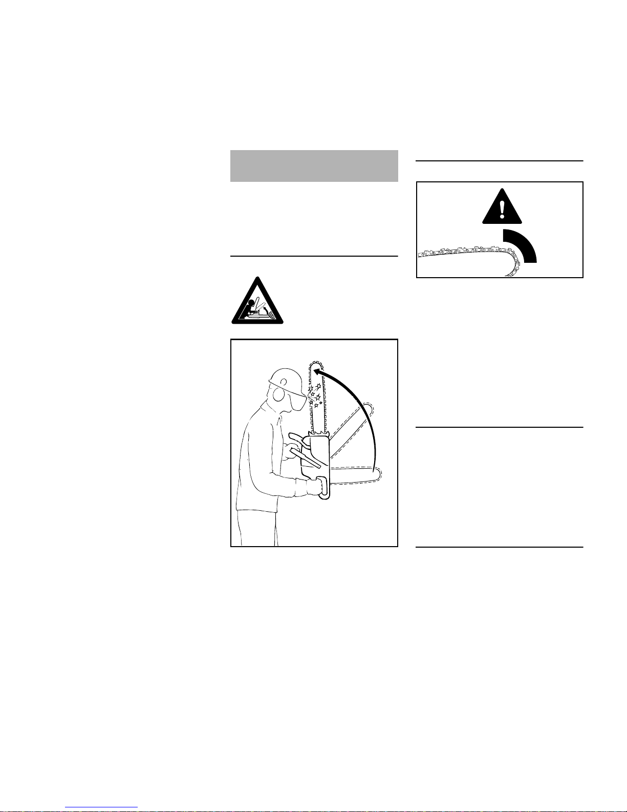
Peligro por rebote
Al producirse un rebote (kickback), la
sierra es lanzada repentinamente y de
forma incontrolable hacia el operario.
Un rebote se produce, p. ej. si
– La cadena entra en contacto
involuntariamente con madera u
otro objeto sólido por el sector del
cuarto superior de la punta de la
espada – p ej. si se toca
involuntariamente otra rama al
desramar
– La cadena queda aprisionada
brevemente en el corte por la punta
de la espada
Freno de cadena QuickStop:
Con este freno se reduce el peligro de
lesiones en determinadas situaciones –
no se puede impedir el rebote mismo. Al
activarse el freno de cadena, ésta se
detiene en una fracción de segundo –
véase el apartado "Freno de cadena" en
este manual de instrucciones.
Disminuir el riesgo de rebote
– Trabajando con prudencia y
correctamente
– Sujetando firmemente la motosierra
bien empuñada con ambas manos
– Trabajando sólo a pleno gas
– Fijándose en la punta de la espada
Fuerzas de reacción
El rebote puede ocasionar cortes mortales.
001BA036 KN
001BA257 KN
Page 11
MS 381
español
9
– No serrando con la punta de la
espada
– Teniendo cuidado con ramas
pequeñas y resistentes, monte bajo
y vástagos – la cadena puede
trabarse en ellos
– No cortando nunca varias ramas a
la vez
– No agachándose demasiado al
trabajar
– No serrando a más altura de los
hombros
– Introduciendo la espada sólo con el
máximo cuidado en un corte ya
empezado
– Trabajando en el "corte de punta"
únicamente si se está familiarizado
con esta técnica de trabajo
– Prestando atención a la posición del
tronco y a fuerzas que puedan
cerrar el corte y aprisionar la
cadena
– Trabajando únicamente con la
cadena correctamente afilada y
tensada – la distancia del limitador
de profundidad no debe ser
demasiado grande
– Empleando una cadena de baja
tendencia al rebote y una espada de
cabeza pequeña
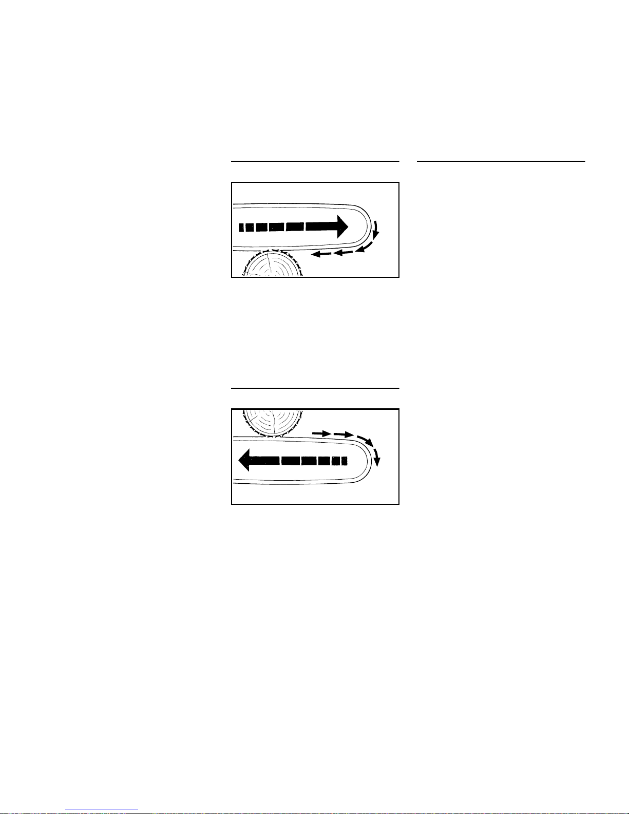
Tirón hacia delante (A)
Cuando, al cortar con el lado inferior de
la espada – corte normal – la cadena se
traba o roza un objeto sólido en la
madera, la motosierra puede ser
absorbida repentinamente hacia el
tronco – para evitarlo, aplicar siempre
de forma segura el tope de garras.
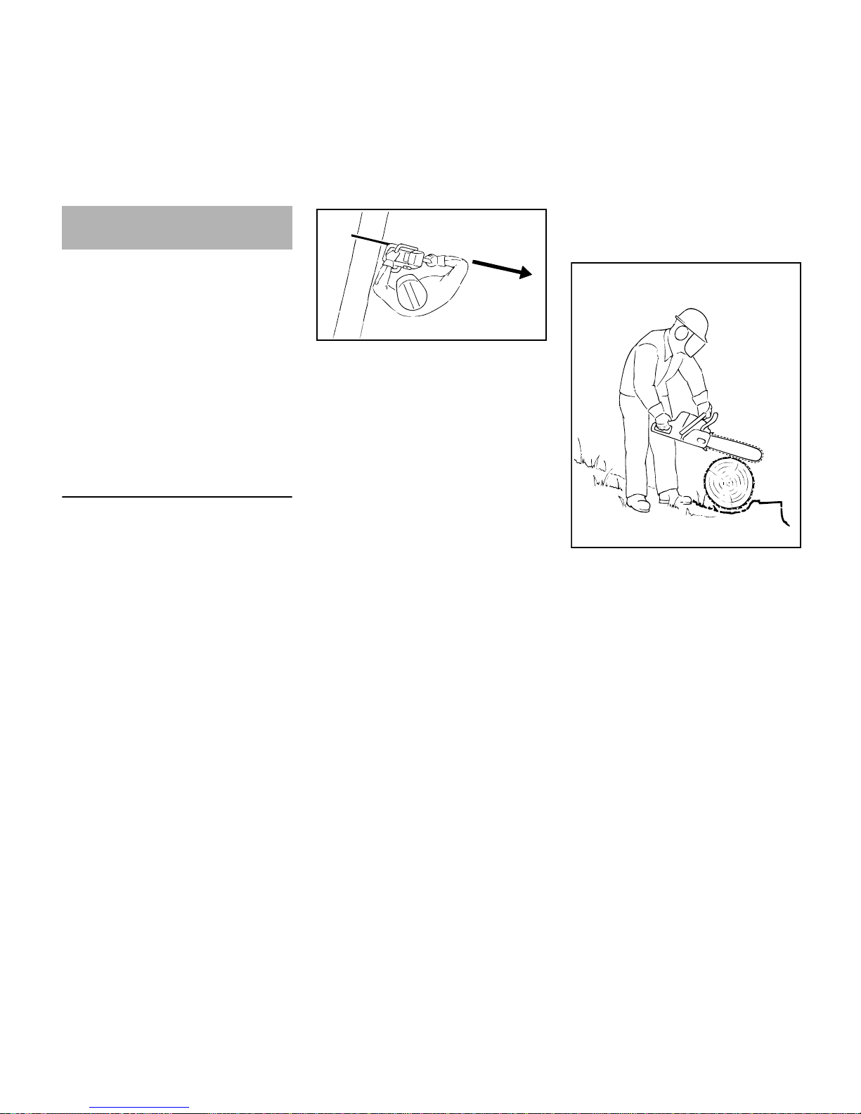
Golpe de retroceso (B)
Cuando, al cortar con el lado superior de
la espada – corte del revés – la cadena
se aprisiona o topa en un objeto sólido
en la madera, la motosierra puede
retroceder de golpe hacia el operario –
para evitarlo:
– No aprisionar el lado superior de la
espada
– No retorcer la espada en el corte
Prestar la máxima atención
– A troncos colgantes
– A troncos que estén bajo tensión
por haber caído desfavorablemente
entre otros árboles
– Al trabajar en troncos tumbados por
el viento
En estos casos, no trabajar con la
motosierra – sino utilizar mordazas, un
torno de cable o un tractor.
Sacar troncos sueltos y desramados.
Efectuar los trabajos de corte en lugares
abiertos.
La madera muerta (madera seca,
podrida o muerta) representa un peligro
considerable y difícil de calcular. La
detección del peligro resulta dificultosa o
prácticamente imposible. Emplear
recursos como tornos de cable o
tractores.
Al talar cerca de carreteras, carriles,
cables de corriente eléctrica, etc.
trabajar con especial precaución. En
caso necesario, informar a la policía, a
las empresas de abastecimiento público
o a la del ferrocarril.
001BA037 KN
A
001BA038 KN
B
Page 12
MS 381
español
10
Los trabajos de aserrado y talado, así
como todos los trabajos relacionados
con ellos (corte de punta, desrame, etc.)
sólo deberán realizarlos quienes hayan
sido formados e instruidos para ello. No
deberán realizar ninguno de estos
trabajos quienes no tengan experiencia
alguna con las técnicas de trabajo – ¡alto
peligro de accidente!
Al tratarse de trabajos de talado, se han
de tener en cuenta sin falta las normas
específicas de los países relativas a la
técnica de talado.
Serrar
No trabajar en la posición de gas de
arranque. En esta posición del
acelerador, no se puede regular el
número de revoluciones del motor.
Trabajar con tranquilidad y prudencia –
sólo en buenas condiciones de luz y
visibilidad. No dañar a otros – trabajar
con prudencia.
A los principiantes les recomendamos
practicar el corte de madera redonda en
un caballete – véase "Serrar madera
delgada".
Emplear en lo posible una espada corta:
la cadena, la espada y el piñón de
cadena tienen que armonizar entre sí y
con la motosierra.
No poner ninguna parte del cuerpo en el
sector de giro prolongado de la cadena.
Retirar la motosierra de la madera sólo
estando la cadena en funcionamiento.
Emplear la motosierra únicamente para
serrar – no hacerlo para apalancar o
apartar ramas o raíces adventicias.
No cortar desde abajo ramas que estén
colgando.
Tener cuidado al cortar madera astillada
– ¡peligro de lesiones por trozos de
madera arrastrados!
No dejar que la motosierra toque
cuerpos extraños: las piedras, clavos,
etc. pueden salir despedidos y dañar la
cadena. La motosierra puede rebotar –
¡peligro de accidente!
Si una cadena en pleno giro topa en una
piedra u otro objeto duro, pueden
generarse chispas por lo que, en
determinadas circunstancias pueden
encenderse materiales que sean
fácilmente inflamables. También las
plantas y maleza en estado seco son
fácilmente inflamables, especialmente
en condiciones meteorológicas de
mucho calor y sequedad. Si existe
peligro de incendio, no emplear la
motosierra cerca de sustancias
fácilmente inflamables, plantas secas o
maleza. Preguntar sin falta a la
autoridad forestal competente si existe
peligro de incendio.
Al trabajar en pendientes, colocarse
siempre en la parte superior o al lado del
tronco o del árbol tumbado. Prestar
atención a troncos que rueden.
Al efectuar trabajos en lo alto:
– Emplear siempre una plataforma
elevadora
– No trabajar nunca sobre una
escalera o estando de pie en el
árbol
– Ni sobre objetos inestables
– No trabajar a una altura superior a
la de los hombros.
– Ni con una mano sola
Aplicar la motosierra al corte a pleno gas
y aplicar firmemente el tope de garras –
no serrar hasta entonces.
Técnica de trabajo
001BA082 KN
001BA033 KN
Page 13
MS 381
español
11
No trabajar nunca sin tope de garras, ya
que la sierra puede arrastrar al operario
hacia delante. Aplicar siempre de forma
segura el tope de garras.
Al final del corte, la motosierra ya no se
apoya en el corte por medio del equipo
de corte. El usuario tiene que absorber
la fuerza del peso de la motosierra –
¡peligro de pérdida del control!
Cortar madera delgada:
– Utilizar un dispositivo de fijación
firme y estable – un caballete
– No sujetar la madera con el pie
– No permitir que otras personas
sujeten la madera ni que ayuden
Desramar:
– Utilizar una cadena de baja
tendencia al rebote
– Apoyar la motosierra en lo posible
– No desramar estando de pie sobre
el tronco
– No serrando con la punta de la
espada
– Prestar atención a ramas que estén
bajo tensión
– No cortando nunca varias ramas a
la vez
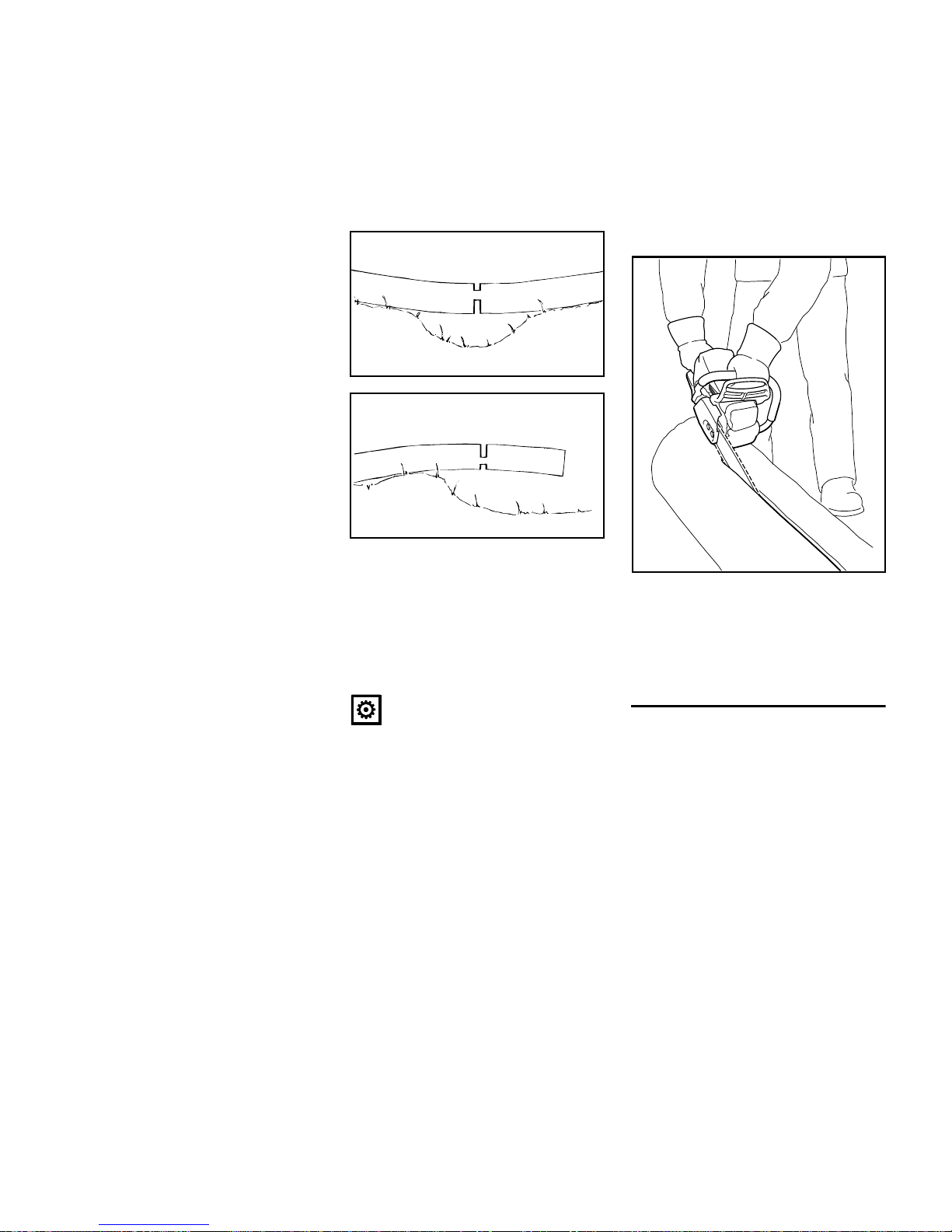
Madera tumbada o parada bajo tensión:
Cortar sin falta en el orden correcto
(primero el lado de presión (1), luego el
lado de tracción (2); de no hacerlo, la
motosierra puede quedar aprisionada o
rebotar en el corte – ¡peligro de lesiones!
N Hacer un corte de descarga en el
lado de presión (1)
N Realizar el corte de tronzado en el
lado de tracción (2)
En el corte de tronzado desde abajo
hacia arriba (corte del revés) – ¡peligro
de golpe de retroceso!
INDICACIÓN
La madera tumbada no debe tocar el
suelo por el punto donde se haga el
corte – de lo contrario, se dañaría la
cadena.
Corte longitudinal:
Técnica de aserrado sin utilizar el tope
de garras – peligro de tirón hacia delante
– aplicar la espada en un ángulo lo más
plano posible – proceder con especial
cuidado – ¡peligro de rebote!
Preparativos para el talado
En la zona de talado sólo deberán
encontrarse personas que participen en
los trabajos de talado.
Controlar que nadie corra peligro por la
caída del árbol talado – las llamadas de
advertencia pueden pasar inadvertidas
por el ruido del motor.
1
001BA151 KN
2
1
001BA152 KN
2
001BA189 KN
Page 14

MS 381
español
12
La distancia hasta el próximo lugar de
trabajo debe ser de al menos 2 veces
y 1/2 la longitud del árbol.
Establecer el sentido de talado y la ruta
de escape
Elegir el espacio del arbolado en el que
se pueda talar el árbol.
Al hacerlo, tener en cuenta:
– La inclinación natural del árbol
– Extensión de ramas
extraordinariamente fuerte,
crecimiento asimétrico, daños en la
madera
– Sentido y velocidad del viento – no
talar si el viento sopla fuerte
– Sentido de la pendiente
– Árboles contiguos
– Carga de nieve
– Tener en cuenta el estado de salud
del árbol – tener especial cuidado
con los daños en el tronco o madera
muerta (madera seca, podrida o
muerta)
A Sentido de talado
B Ruta de escape (análogamente, vía
de retirada)
– Establecer rutas de escape para
todos los participantes en los
trabajos – en un ángulo de unos 45°
en diagonal en dirección contraria a
la de caída
– Limpiar las rutas de escape, apartar
los obstáculos
– Dejar las herramientas y máquinas
a una distancia segura – pero no en
las rutas de escape
– Al talar, situarse sólo en el lateral
del tronco que vaya a caer, y
retroceder sólo lateralmente hacia
la ruta de escape
– En pendientes pronunciadas,
establecer las rutas de escape
– Al retroceder, prestar atención a las
ramas que caigan y fijarse en la
zona de la copa
Preparar la zona de trabajo en el tronco
– Quitar las ramas, la maleza y los
obstáculos que molesten de la zona
de trabajo en torno al tronco –
postura estable para todos los
ocupados
– Limpiar a fondo el pie del tronco
(p. ej. con el hacha) – la arena,
piedras y otros cuerpos extraños
hacen que la cadena se vuelva
roma
– Cortar las raíces adventicias
grandes: primero la más grande –
proceder primero en sentido vertical
y luego en sentido horizontal – sólo
al tratarse de madera sana
001BA088 LÄ
2
/
1
2
1 1
/
1
2
B
001BA040 KN
A
45°
45°
B
001BA146 KN
Page 15

MS 381
español
13
Muesca de caída
Preparar la muesca de caída
La muesca de caída (C) determina el
sentido de talado.
Importante:
– Trazar la muesca de caída, en
ángulo recto respecto del sentido
de talado
– Serrar lo más cerca posible del
suelo
– Cortar 1/5 hasta un máx. de 1/3 del
diámetro del tronco
Establecer el sentido de talado – con
marca de talado en la cubierta y en la
caja del ventilador
Esta motosierra está provista de una
marca de talado en la cubierta y la caja
del ventilador. Emplear esta marca de
talado.
Establecer la muesca de caída
Al cortar la muesca de caída, alinear la
motosierra de manera que la muesca de
caída quede en ángulo recto respecto
del sentido de talado.
En la forma de proceder para trazar la
muesca de caída con un corte inferior
horizontal (corte horizontal) y corte
superior biselado (corte oblicuo) se
admiten varias secuencias – tener en
cuenta las normas específicas de los
países relativas a la técnica de talado.
N Trazar el corte inferior horizontal
(corte horizontal)
N Realizar el corte superior biselado
(corte oblicuo) unos 45°- 60°
respecto del corte inferior horizontal
Comprobar el sentido de talado
N Acercar la motosierra a la base de
la muesca de caída por la espada.
La marca de talado tiene que estar
orientada hacia el sentido de talado
establecido – en tanto sea
necesario, corregir el sentido de
talado recortando
correspondientemente la muesca
de caída
001BA271 KN
C
C
001BA153 KN
001BA153 KN
Page 16

MS 381
español
14
Cortes de albura
Los cortes de albura impiden que se
desgarre la albura al talar el tronco en
maderas de fibras largas – cortar en
ambos lados del tronco a la altura de la
base de la muesca de caída hasta
aprox. 1/10 del diámetro del tronco – al
tratarse de troncos de cierto grosor,
cortar hasta el ancho de la espada,
como máximo.
Al tratarse de madera enferma, no hacer
cortes de albura.
Fundamentos relativos al corte de
talado
Medidas del tronco
La muesca de caída (C) determina el
sentido de talado.
La arista de ruptura (D) hace el papel de
bisagra en la caída del árbol.
– Ancho de la arista de ruptura:
aprox. 1/10 del diámetro del tronco
– No cortar de ninguna manera la
arista de ruptura al efectuar el corte
de talado – de hacerlo, el sentido de
caída puede divergir del previsto –
¡peligro de accidente!
– Al tratarse de troncos podridos,
dejar una arista de ruptura más
ancha
Con el corte de talado (E) se tala el
árbol.
– Exactamente horizontal
– 1/10 (3 cm, como mín.) del ancho
de la arista de ruptura (D) por
encima de la parte inferior de la
muesca de caída (C)
La banda de retención (F) o la banda de
seguridad (G) apoya el árbol y lo
asegura contra la caída prematura.
– Ancho de la banda: aprox. 1/10
hasta 1/5 del diámetro del tronco
– No cortar de ningún modo la banda
al efectuar el corte de talado
– Al tratarse de troncos podridos,
dejar una franja más ancha
Corte de punta
– Como corte de descarga al trocear
– En trabajos de talla de madera
001BA150 KN
G
001BA259 KN
C
E
D
1/10
C
Page 17

MS 381
español
15
N Utilizar cadenas de baja tendencia
al rebote y trabajar con especial
cuidado
1. Aplicar la espada por el lado inferior
de la punta – no hacerlo por el lado
superior – ¡peligro de rebote! Serrar
a pleno gas hasta que la espada se
haya introducido el doble de su
ancho en el tronco
2. Girar lentamente a la posición de
corte de punta – ¡peligro de rebote o
golpe de retroceso!
3. Efectuar con cuidado el corte de
punta – ¡peligro de golpe de
retroceso!
Si es posible, emplear una marca para
el corte de punta. La marca para el corte
de punta y el lado superior o el inferior
de la espada son paralelos.
En el corte de punta, la marca para
dicho corte ayuda a conformar la arista
de rotura en paralelo, es decir, del
mismo grosor en todos los puntos. Para
ello, poner la marca para el corte de
punta en paralelo con la muesca de
caída.
Cuñas de talado
Colocar la cuña de talado lo antes
posible, es decir, hacerlo en cuanto deje
de esperarse obstáculos para el corte.
Aplicar la cuña al corte de talado e
introducirla mediante herramientas
apropiadas.
Emplear sólo cuñas de aluminio o
plástico – no emplear cuñas de acero.
Las cuñas de acero pueden dañar la
cadena y pueden provocar un rebote
peligroso.
Elegir cuñas de talado apropiadas en
función del diámetro del tronco y del
ancho del intersticio de corte
(análogamente, corte de talado (E)).
Para elegir la cuña de talado (longitud,
ancho y altura apropiados), acudir a un
distribuidor especializado STIHL.
Elegir un corte de talado apropiado
La elección del corte de talado
apropiado depende de los mismos
aspectos que se han de tener en cuenta
al establecer el sentido de talado y las
rutas de escape.
Se distinguen varios modelos diferentes
de estos aspectos. En este manual de
instrucciones se describen sólo los dos
modelos que aparecen con mayor
frecuencia:
Corte de talado con banda de seguridad
(árbol normal)
A) Troncos delgados
Realizar este corte de talado si el
diámetro del tronco es más pequeño
que la longitud de corte de la motosierra.
3.
001BA269 KN
1.
2.
001BA270 KN
Izquier
da:
Árbol normal – árbol en
posición vertical con copa
uniforme
Derecha:
Árboles que cuelguen hacia
delante – la copa está orientada en el sentido de talado
001BA260 KN
Page 18

MS 381
español
16
Antes de iniciar el corte de talado, avisar
a los demás en voz alta con "¡atención!".
N Hacer de punta un corte de
talado (E) – al hacerlo, insertar la
espada por completo
N Aplicar el tope de garras detrás de
la arista de ruptura y utilizarlo como
punto de giro – cambiar lo menos
posible la posición de la motosierra
N Conformar el corte de talado hasta
la arista de ruptura (1)
– Al hacerlo, no cortar la arista de
ruptura
N Conformar el corte de talado hasta
la banda de seguridad (2)
– Al hacerlo, no cortar la banda de
seguridad
N Poner una cuña de talado (3)
Inmediatamente antes de caer el árbol,
avisar por segunda vez con "¡atención!".
N Cortar desde fuera la banda de
seguridad, horizontalmente al nivel
del corte de talado con los brazos
extendidos
B) Troncos gruesos
Realizar este corte de talado si el
diámetro del tronco es más grande que
la longitud de corte de la motosierra.
Antes de iniciar el corte de talado, avisar
a los demás en voz alta con "¡atención!".
N Aplicar el tope de garras a la altura
del corte de talado y utilizarlo como
punto de giro – cambiar lo menos
posible la posición de la motosierra
N Introducir la punta de la espada en
la madera delante de la arista de
ruptura (1) – sostener la motosierra
en posición absolutamente
horizontal y girarla lo máximo
posible
N Conformar el corte de talado hasta
la arista de ruptura (2)
– Al hacerlo, no cortar la arista de
ruptura
N Conformar el corte de talado hasta
la banda de seguridad (3)
– Al hacerlo, no cortar la banda de
seguridad
001BA261 KN
1.
2.
3.
001BA273 KN
4.
001BA263 KN
1.
2.
3.
5.
Page 19

MS 381
español
17
El corte de talado se continúa realizando
desde el lado opuesto del tronco.
Prestar atención a que el segundo corte
esté al mismo nivel que el primero.
N Realizar de punta el corte de talado
N Conformar el corte de talado hasta
la arista de ruptura (4)
– Al hacerlo, no cortar la arista de
ruptura
N Conformar el corte de talado hasta
la banda de seguridad (5)
– Al hacerlo, no cortar la banda de
seguridad
N Poner una cuña de talado (6)
Inmediatamente antes de caer el árbol,
avisar por segunda vez con "¡atención!".
N Cortar desde fuera la banda de
seguridad, horizontalmente al nivel
del corte de talado con los brazos
extendidos
Corte de talado con banda de retención
(árboles que cuelguen hacia delante)
A) Troncos delgados
Realizar este corte de talado si el
diámetro del tronco es más pequeño
que la longitud de corte de la motosierra.
N Introducir de punta la espada en el
tronco hasta que salga por el otro
lado del mismo
N Conformar el corte de talado (E)
hacia la arista de ruptura (1)
– Exactamente horizontal
– Al hacerlo, no cortar la arista de
ruptura
N Conformar el corte de talado hacia
la banda de retención (2)
– Exactamente horizontal
– Al hacerlo, no cortar la banda de
retención
Inmediatamente antes de caer el árbol,
avisar por segunda vez con "¡atención!".
N Cortar desde fuera la banda de
retención, oblicuamente desde
arriba, con los brazos extendidos
6.
001BA274 KN
1.
2.
001BA265 KN
001BA266 KN
Page 20

MS 381
español
18
B) Troncos gruesos
Realizar este corte de talado si el
diámetro del tronco es más grande que
la longitud de corte de la motosierra.
N Aplicar el tope de garras detrás de
la banda de retención y utilizarlo
como punto de giro – cambiar lo
menos posible la posición de la
motosierra
N Introducir la punta de la espada en
la madera delante de la arista de
ruptura (1) – sostener la motosierra
en posición absolutamente
horizontal y girarla lo máximo
posible
– Al hacerlo, no cortar la banda de
retención ni la arista de ruptura
N Conformar el corte de talado hasta
la arista de ruptura (2)
– Al hacerlo, no cortar la arista de
ruptura
N Conformar el corte de talado hasta
la banda de retención (3)
– Al hacerlo, no cortar la banda de
retención
El corte de talado se continúa realizando
desde el lado opuesto del tronco.
Prestar atención a que el segundo corte
esté al mismo nivel que el primero.
N Aplicar el tope de garras detrás de
la arista de ruptura y utilizarlo como
punto de giro – cambiar lo menos
posible la posición de la motosierra
N Introducir la punta de la espada en
la madera delante de la banda de
retención (4) – sostener la
motosierra en posición
absolutamente horizontal y girarla
lo máximo posible
N Conformar el corte de talado hasta
la arista de ruptura (5)
– Al hacerlo, no cortar la arista de
ruptura
N Conformar el corte de talado hasta
la banda de retención (6)
– Al hacerlo, no cortar la banda de
retención
Inmediatamente antes de caer el árbol,
avisar por segunda vez con "¡Atención!".
N Cortar desde fuera la banda de
retención, oblicuamente desde
arriba, con los brazos extendidos
001BA267 KN
1.
2.
3.
4.
5.
6.
001BA268 KN
Page 21

MS 381
español
19
La cadena, la espada y el piñón de
cadena forman el equipo de corte.
El equipo de corte contenido en el
volumen de suministro está armonizado
óptimamente con la motosierra.
– El paso (t) de la cadena (1), del
piñón de cadena y de la estrella de
inversión de la espada Rollomatic
tienen que coincidir
– El grosor del eslabón impulsor (2)
de la cadena (1) tiene que
armonizar con el ancho de ranura
de la espada (3)
En el caso de emparejar componentes
que no armonicen entre sí, el equipo de
corte se podrá dañar irreparablemente
ya tras un breve tiempo de servicio.
Protector de la cadena
El volumen de suministro contiene un
protector de cadena apropiado para el
equipo de corte.
Si se emplean espadas de diferente
longitud en una motosierra, se ha de
utilizar siempre un protector de cadena
apropiado que cubra la espada por
completo.
En el lateral del protector de cadena se
ha grabado la indicación relativa a la
longitud de la correspondiente espada
apropiada.
Para espadas que superan los 90 cm,
se requiere una prolongación del
protector de cadena. Para espadas que
superan los 120 cm, se requieren dos
prolongaciones del protector de cadena.
Según el equipamiento, la prolongación
del protector de cadena forma parte del
volumen de suministro o se puede
adquirir como accesorio especial.
Montar la prolongación del protector de
cadena
N Unir la prolongación del protector
de cadena y el protector de cadena
– los salientes de enclavamiento (1)
tienen que encastrar en el protector
de cadena
Equipo de corte
001BA248 KN
1
2
3
a
001BA244 KN
001BA245 KN
1
1
Page 22

MS 381
español
20
Desmontar la tapa del piñón de cadena
N Desenroscar las tuercas y quitar la
tapa del piñón de cadena
N Girar el tornillo (1) hacia la izquierda
hasta que la corredera de
sujeción (2) esté aplicada al lado
izquierdo del rebaje de la caja
Desactivar el freno de cadena
N Tirar del protector salvamanos
hacia el asidero tubular hasta que
se oiga hacer clic – el freno de
cadena está desactivado
Colocar la cadena
ADVERTENCIA
Ponerse guantes protectores – peligro
de lesiones por los dientes de corte
afilados.
N Colocar la cadena, comenzando
por la punta de la espada
N Colocar la espada sobre los
tornillos (1) – las aristas de corte de
la cadena tienen que estar
orientadas hacia la derecha
N Colocar el orificio de fijación (2)
sobre el pivote de la corredera
tensora – al mismo tiempo, colocar
la cadena sobre el piñón (3)
N Girar el tornillo (4) hacia la derecha
hasta que la cadena cuelgue ya
sólo un poco por la parte inferior – y
los salientes de los eslabones
impulsores penetren en la ranura de
la espada
N Volver a colocar la tapa del piñón de
cadena – y apretar las tuercas a
mano sólo ligeramente
N Para continuar, véase "Tensar la
cadena"
Montar la espada y la
cadena
143BA034 KN
1
2
001BA185 KN
001BA186 KN
143BA003 KN
3
1
1
2
4
001BA187 KN
Page 23

MS 381
español
21
Para el retensado durante el trabajo:
N Parar el motor
N Aflojar las tuercas
N Elevar la espada por la punta
N Girar el tornillo (1) hacia la derecha
con un destornillador hasta que la
cadena quede aplicada al lado
inferior de la espada
N Seguir levantando la espada y
apretar firmemente las tuercas
N Para continuar, véase "Comprobar
la tensión de la cadena de
aserrado"
Una cadena nueva se ha de retensar
con más frecuencia que otra que lleve
más tiempo en servicio.
N Controlar con cierta frecuencia la
tensión de la cadena - véase
"Indicaciones para el servicio"
N Parar el motor
N Ponerse guantes protectores
N La cadena tiene que estar aplicada
al lado inferior de la espada - y,
estando desactivado el freno de
cadena, se tiene que poder mover
sobre la espada tirando de aquella
con la mano
N De ser necesario, retensar la
cadena
Una cadena nueva se ha de retensar
con más frecuencia que otra que lleve
más tiempo en servicio.
N Controlar con cierta frecuencia la
tensión de la cadena - véase
"Indicaciones para el servicio"
El motor se ha de alimentar con una
mezcla compuesta por gasolina y aceite
de motor.
ADVERTENCIA
Evitar el contacto cutáneo con la
gasolina y la inhalación de vapores de la
misma.
STIHL MotoMix
STIHL recomienda emplear
STIHL MotoMix. Este combustible
mezclado ya está exento de benceno y
plomo, se distingue por un alto índice
octano y tiene siempre la proporción de
mezcla correcta.
El STIHL MotoMix está mezclado para
obtener la máxima durabilidad del motor
con el aceite de motor de dos tiempos
HP Ultra STIHL.
MotoMix no está disponible en todos los
mercados.
Mezclar combustible
INDICACIÓN
Si los productos de servicio no son
apropiados o la proporción de la mezcla
no corresponde a la norma se pueden
producir serios daños en el motor. La
gasolina o el aceite de motor de mala
calidad pueden dañar el motor, los
retenes, tuberías y el depósito de
combustible.
Tensar la cadena
1
133BA024 KN
Comprobar la tensión de la
cadena
143BA007 KN
Combustible
Page 24

MS 381
español
22
Gasolina
Emplear sólo gasolina de marca con un
índice octano de 90 ROZ, como mínimo
– con o sin plomo.
Las máquinas equipadas con
catalizador se han de alimentar con
gasolina sin plomo.
INDICACIÓN
En el caso de emplear varias cargas del
depósito de combustible con plomo,
puede disminuir notablemente el efecto
del catalizador.
La gasolina con una proporción de
alcohol superior al 10% puede provocar
anomalías de funcionamiento en
motores con ajuste manual del
carburador, por lo que no se deberá
emplear para alimentar estos motores.
Los motores equipados con M-Tronic
suministran plena potencia empleando
gasolina con una proporción de alcohol
de hasta 25% (E25).
Aceite de motor
Emplear sólo aceite de motor de dos
tiempos de calidad – preferentemente,
el aceite de motor de dos tiempos STIHL
HP, HP Super o HP Ultra; éstos aceites
armonizan óptimamente con los
motores STlHL. El más alto rendimiento
y la máxima durabilidad del motor la
garantiza el HP Ultra.
Estos aceites de motor no están
disponibles en todos los mercados.
En máquinas con catalizador de gases
de escape, sólo se deberá emplear
aceite de motor de dos tiempos STIHL
1:50 para realizar la mezcla.
Proporción de la mezcla
Con aceite de motor de dos tiempos
STIHL 1:50; 1:50 = 1 parte de aceite +
50 partes de gasolina
Ejemplos
N En un bidón homologado para
combustible, echar primero aceite
de motor, luego gasolina, y
mezclarlos bien
Guardar la mezcla de combustible
Sólo en bidones homologados para
combustible, guardándolos en un lugar
seco, fresco y seguro, protegidos contra
la luz y el sol.
La mezcla de combustible envejece –
mezclar sólo la cantidad que se necesite
para algunas semanas. No guardar la
mezcla de combustible durante más de
30 días. El efecto de la luz, el sol, altas
o bajas temperaturas, pueden echar a
perder con mayor rapidez la mezcla de
combustible.
Sin embargo, la STIHL MotoMix se
puede almacenar 2 años sin problemas.
N Antes de repostar, agitar con fuerza
el bidón con la mezcla
ADVERTENCIA
En el bidón puede generarse presión –
abrirlo con cuidado.
N Limpiar de vez en cuando a fondo el
depósito de combustible y el bidón
Recoger el combustible residual y el
líquido utilizado para la limpieza y
llevarlos a los puntos limpios.
Cantidad de
gasolina
Aceite de dos tiempos
STIHL 1:50
Litros Litros (ml)
10,02(20)
5 0,10 (100)
10 0,20 (200)
15 0,30 (300)
20 0,40 (400)
25 0,50 (500)
Page 25

MS 381
español
23
Preparar la máquina
N Antes de repostar combustible,
limpiar el cierre y sus alrededores, a
fin de que no penetre suciedad en el
depósito
N Posicionar la máquina, de manera
que el cierre esté orientado hacia
arriba
Diferentes marcaciones en los cierres
de depósito
Los cierres de depósito y los depósitos
de combustible pueden estar marcados
de forma diferente.
Según la ejecución, el cierre de depósito
y el depósito de combustible pueden
carecer de marcación.
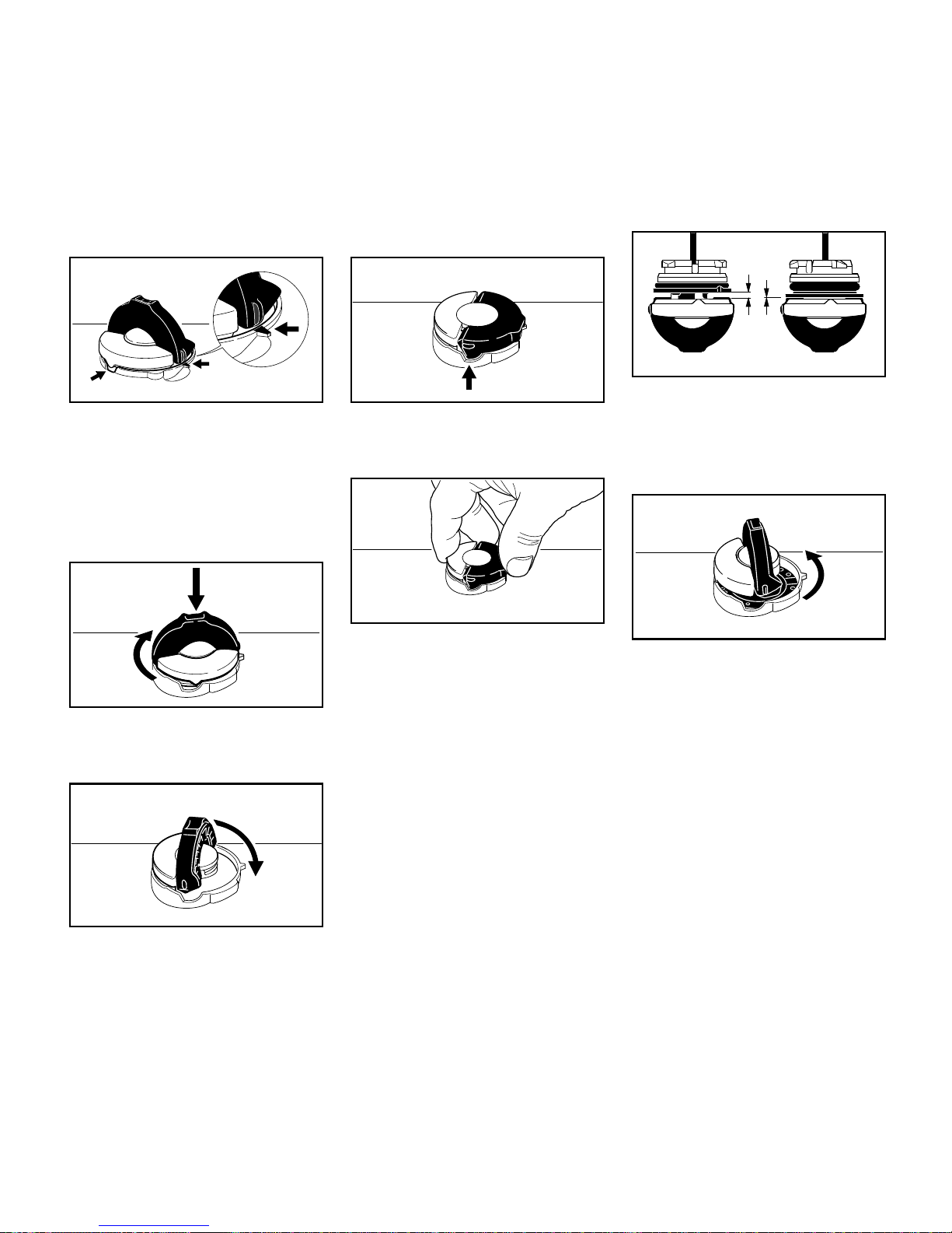
Cierre de depósito sin marcación
Abrir
N Abrir el estribo hasta que se
encuentre en posición vertical
N Girar el cierre del depósito en
sentido antihorario
(aprox. 1/4 de vuelta)
N Quitar el cierre del depósito
Repostar combustible
Al repostar, no derramar combustible ni
llenar el depósito hasta el borde.
STIHL recomienda utilizar el sistema de
llenado STIHL para combustible
(accesorio especial).
N Repostar combustible
Repostar combustible
001BA229 KN
Izquierda: cierre de depósito – sin
marcaciones
Derecha: cierre de depósito – con
marcaciones en el cierre y
en el depósito
001BA240 KN
001BA218 KN
001BA219 KN
001BA224 KN
Page 26
MS 381
español
24
Cerrar
El estribo está en posición vertical:
N Aplicar el cierre del depósito – las
marcas de posición en el cierre del
depósito y en la boca de llenado
tienen que estar alineadas entre sí
N Presionar el cierre del depósito
hacia abajo hasta el tope
N Mantener el cierre del depósito
presionado y girarlo en sentido
horario hasta que encastre
N Abatir el estribo hasta el tope
Comprobar el enclavamiento
– El saliente del estribo tiene que
encontrarse por completo en el
rebaje (flecha)
N Agarrar el cierre del depósito – éste
está correctamente enclavado, si
no se deja mover ni quitar
Si el cierre del depósito no se deja
mover o quitar
La parte inferior del cierre del depósito
está girada respecto de la parte
superior:
N Aplicar el cierre del depósito y
girarlo en sentido antihorario hasta
que encaje en el asiento de la boca
de llenado
N Seguir girando el cierre del depósito
en sentido antihorario
(aprox. 1/4 de vuelta) – así se gira la
parte inferior del cierre del depósito
a la posición correcta
N Girar el cierre del depósito en
sentido horario y cerrarlo – véase
los apartados "Cerrar" y
"Comprobar el enclavamiento"
001BA220 KN
001BA221 KN
001BA222 KN
001BA223 KN
001BA225 KN
Izquierda: parte inferior del cierre del
depósito, girada
Derecha: parte inferior del cierre del
depósito, en posición
correcta
001BA227 KN
001BA226 KN
Page 27

MS 381
español
25
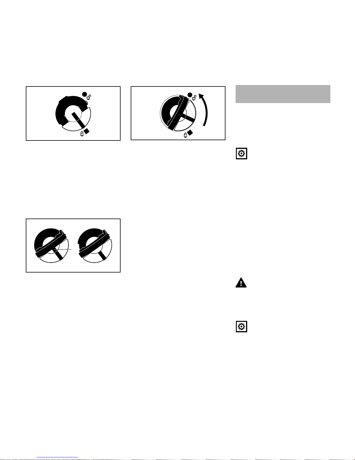
Cierre de depósito con marcación
Abrir
N Desplegar el estribo
N Girar el cierre del depósito
(aprox. 1/4 de vuelta)
Las marcas en el cierre del depósito y
en el depósito de combustible tienen
que estar alineadas entre sí
N Quitar el cierre del depósito
Repostar combustible
Al repostar, no derramar combustible ni
llenar el depósito hasta el borde.
STIHL recomienda utilizar el sistema de
llenado STIHL para combustible
(accesorio especial).
N Repostar combustible
Cerrar
El estribo está en posición vertical:
N Aplicar el cierre del depósito – las
marcas en el cierre del depósito y
en el depósito de combustible
tienen que estar alineadas entre sí
N Presionar el cierre del depósito
hacia abajo hasta el tope
N Mantener el cierre del depósito
presionado y girarlo en sentido
horario hasta que encastre
Entonces quedan alineadas entre sí las
marcas en el cierre del depósito y en el
depósito de combustible
N Cerrar el estribo
001BA236 KN
001BA232 KN
001BA234 KN
001BA237 KN
001BA234 KN
001BA233 KN
001BA231 KN
001BA235 KN
Page 28
MS 381
español
26
El cierre del depósito está enclavado
Si el cierre del depósito no se puede
enclavar con el depósito de combustible
La parte inferior del cierre del depósito
está girada respecto de la parte
superior.
N Quitar el cierre del depósito de
combustible y observarlo desde la
parte superior
N Aplicar el cierre del depósito y
girarlo en sentido antihorario hasta
que encaje en el asiento de la boca
de llenado
N Seguir girando el cierre del depósito
en sentido antihorario
(aprox. 1/4 de vuelta) – así se gira la
parte inferior del cierre del depósito
a la posición correcta
N Girar el cierre del depósito en
sentido horario y cerrarlo – véase el
apartado "Cerrar"
Para la lubricación automática y
duradera de la cadena y la espada –
emplear sólo aceite lubricante para
cadenas de calidad – utilizar
preferentemente el STIHL BioPlus que
es rápidamente biodegradable.
INDICACIÓN
El aceite biológico para la lubricación de
la cadena tiene que tener suficiente
resistencia al envejecimiento (p. ej.
STIHL BioPlus). El aceite con escasa
resistencia al envejecimiento tiende a
resinificarse rápidamente. Como
consecuencia, se forman depósitos
sólidos, difíciles de limpiar,
especialmente en el sector del
accionamiento de la cadena y en la
cadena – que incluso provocan el
bloqueo de la bomba de aceite.
La duración de la cadena y la espada
depende en gran manera de la
naturaleza del aceite lubricante –
emplear por ello sólo aceite lubricante
especial para cadenas.
ADVERTENCIA
¡No emplear aceite usado! El aceite
usado puede provocar cáncer de piel si
el contacto cutáneo es prolongado y
repetido y daña el medio ambiente
INDICACIÓN
El aceite usado no posee las
propiedades lubricantes necesarias y no
es apropiado para la lubricación de la
cadena.
Izquierda: Parte inferior del cierre del
depósito, girada – la marca
del interior (1) está alineada con la marca del
exterior
Derecha: Parte inferior del cierre del
depósito, en la posición
correcta – la marca del
interior se encuentra
debajo del estribo. Ésta no
queda alineada con la
marca del exterior
001BA241 KN
1
001BA238 KN
001BA239 KN
Aceite lubricante de cadena
Page 29
MS 381
español
27
Preparar la máquina
N Limpiar a fondo el cierre del
depósito de aceite y su entorno, a
fin de que no penetre suciedad en el
depósito
N Posicionar la máquina, de manera
que el cierre del depósito esté
orientado hacia arriba
N Abrir el cierre del depósito
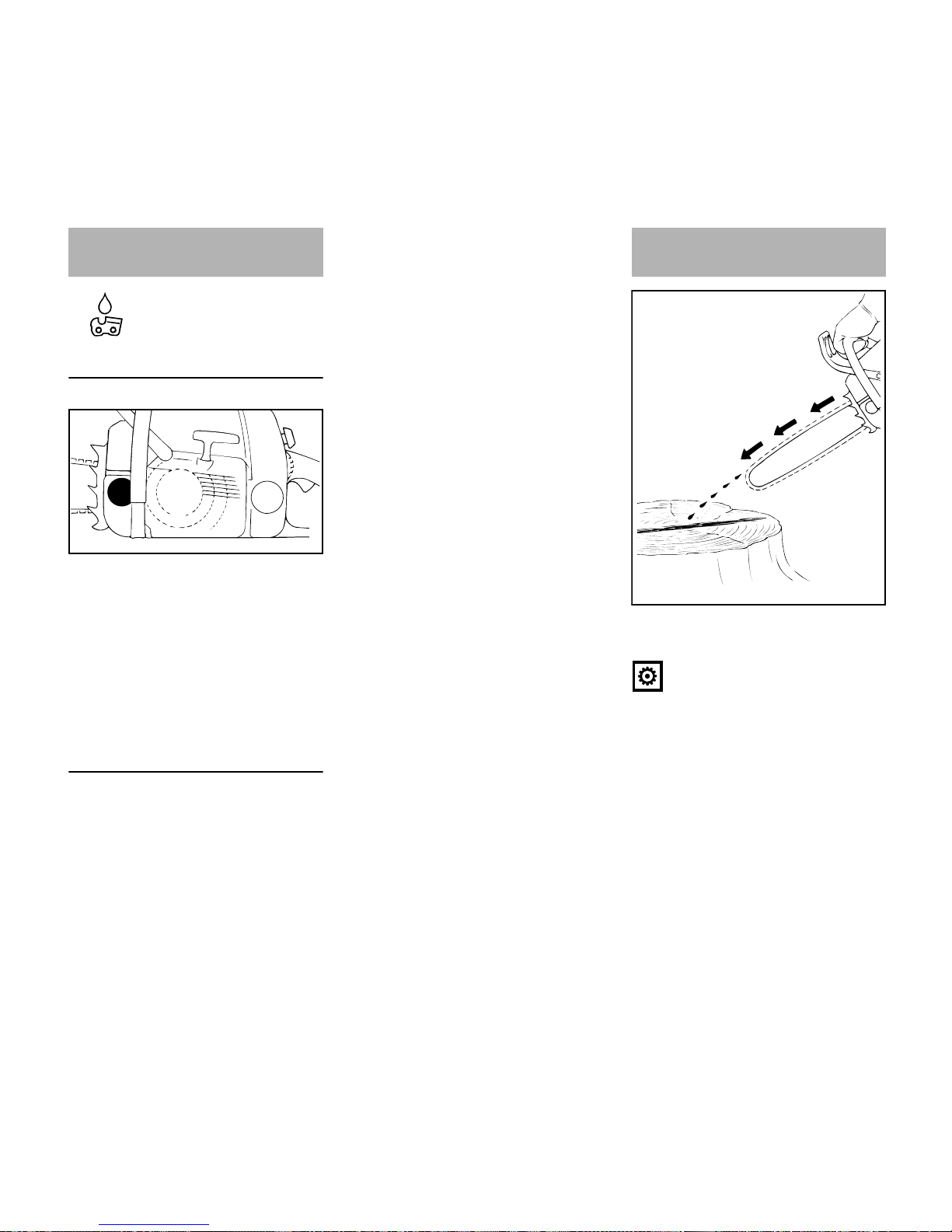
Repostar aceite de lubricación para la
cadena
N Echar aceite lubricante para
cadenas – cada vez que se haya
repostado combustible
Al repostar, no derramar aceite
lubricante ni llenar el depósito hasta el
borde.
STIHL recomienda utilizar el sistema de
llenado STIHL para aceite lubricante
para cadenas (accesorio especial).
N Cerrar el cierre del depósito
Al vaciarse el depósito de combustible,
tiene que quedar todavía un resto de
aceite lubricante de cadena en el
depósito.
Si no baja el nivel de aceite en el
depósito, podrá existir una irregularidad
en el suministro de aceite lubricante:
comprobar la lubricación de la cadena,
limpiar los canales de aceite, acudir
eventualmente a un distribuidor
especializado. STIHL recomienda
encargar los trabajos de mantenimiento
y las reparaciones siempre a un
distribuidor especializado STIHL.
La cadena tiene que despedir siempre
un poco de aceite.
INDICACIÓN
¡No trabajar nunca sin lubricación de la
cadena! Si la cadena funciona en seco,
se destruye irreparablemente el equipo
de corte en breve tiempo. Antes de
empezar a trabajar, controlar siempre la
lubricación de la cadena y el nivel de
aceite en el depósito.
Todas las cadenas nuevas necesitan un
tiempo de rodaje de 2 a 3 minutos.
Tras el rodaje, comprobar la tensión de
la cadena y corregirla si es necesario –
véase "Comprobar la tensión de la
cadena".
Repostar aceite de
lubricación para la cadena
001BA158 KN
Comprobar la lubricación de
la cadena
143BA024 KN
Page 30
MS 381
español
28
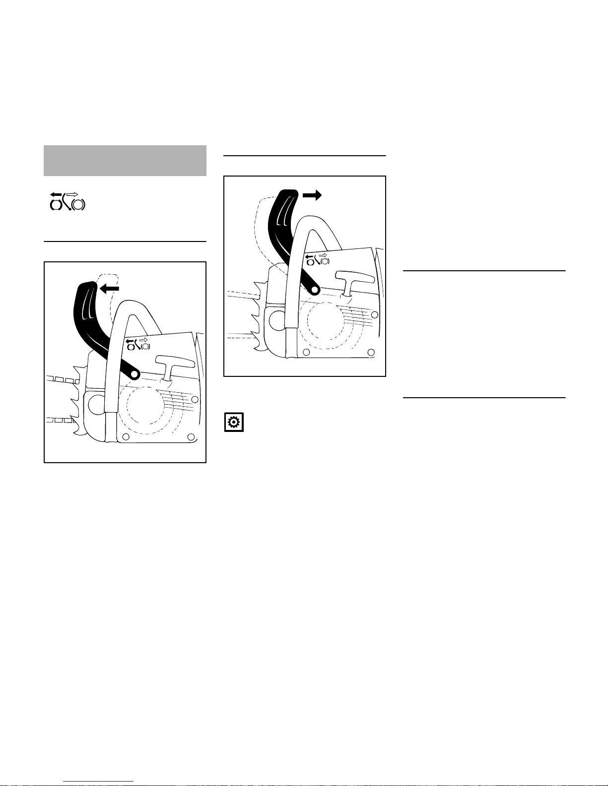
Bloquear la cadena
– En caso de emergencia
– Al arrancar
– En ralentí
Oprimir el protector salvamanos hacia la
punta de la espada con la mano
izquierda – o automáticamente debido al
rebote de la sierra: la cadena se bloquea
– y se para.
Desactivar el freno de cadena
N Tirar del protector salvamanos
hacia el asidero tubular
INDICACIÓN
Antes de dar gas (excepto al controlar el
funcionamiento) y antes de serrar, se ha
de desactivar el freno de cadena.
Un número de revoluciones del motor
elevado con el freno de cadena
bloqueado (la cadena permanece
parada) provoca daños ya tras un breve
tiempo en el motor y el accionamiento
de la cadena (embrague, freno de
cadena).
El freno de cadena se activa
automáticamente al producirse un
rebote de la sierra lo suficientemente
fuerte – por la inercia de masas del
protector salvamanos: el protector
salvamanos se mueve rápidamente
hacia la punta de la espada – aun
cuando la mano izquierda no se
encuentre en el asidero tubular, detrás
del protector salvamanos, como p. ej. en
el corte de talado.
El freno de cadena funciona
únicamente, si no se ha modificado
nada en el protector salvamanos.
Controlar el funcionamiento del freno de
cadena
Siempre antes de empezar a trabajar:
bloquear la cadena estando el motor en
ralentí (oprimir el protector salvamanos
contra la punta de la espada) y acelerar
a fondo brevemente (máx. 3 seg.) – la
cadena no deberá moverse. El protector
salvamanos deberá estar limpio y
moverse con facilidad.
Mantenimiento del freno de cadena
El freno de cadena está sometido a
desgaste por fricción (desgaste natural).
Para que pueda cumplir sus funciones,
deberá ser sometido con regularidad a
un mantenimiento y cuidados por
personal instruido. STIHL recomienda
encargar los trabajos de mantenimiento
y las reparaciones siempre a un
distribuidor especializado STIHL. Se
han de observar los siguientes
intervalos:
Freno de cadena
143BA011 KN
143BA012 KN
Aplicación a jornada
completa: cada 3 meses
Aplicación a tiempo
parcial: cada 6 meses
Aplicación ocasional: anualmente
Page 31

MS 381
español
29
Posiciones de la palanca del mando
unificado
1Stop0 – Motor parado – el
encendido está desconectado
2 Posición de funcionamiento F – el
motor está en marcha o puede
arrancar
3 Gas de arranque – en esta posición
se arranca el motor caliente – la
palanca del mando unificado pasa a
la posición de funcionamiento al
accionar el acelerador
4 Mariposa de arranque cerrada – en
esta posición se arranca el motor
frío
Ajustar la palanca del mando unificado
Para ajustar la palanca del mando
unificado de la posición de
funcionamiento F a mariposa de
arranque cerrada (4), oprimir el bloqueo
del acelerador y el acelerador al mismo
tiempo y retenerlos – ajustar la palanca
del mando unificado.
Para el ajuste a gas de arranque (3),
poner primero la palanca del mando
unificado en mariposa de arranque
cerrada (4), oprimir luego dicha palanca
a la posición de gas de arranque (3).
El cambio a la posición de gas de
arranque (3) sólo es posible desde la
posición de mariposa de arranque
cerrada (4).
Oprimiendo el bloqueo del acelerador y
pulsando ligeramente al mismo tiempo
el acelerador, la palanca del mando
unificado salta de la posición de gas de
arranque (3) a la posición de
funcionamiento F.
Para desconectar el motor, poner la
palanca del mando unificado en Stop 0.
Posición de mariposa de arranque
cerrada (4)
– Con el motor frío
– Si el motor se para tras el arranque
al dar gas
– Si el depósito se ha vaciado con el
motor en marcha (el motor se ha
parado)
Posición de gas de arranque (3)
– Con el motor caliente (en cuanto el
motor haya funcionado aprox. un
minuto)
– Tras el primer encendido
– Tras ventilar la cámara de
combustión, si el motor se había
ahogado
Sujetar la motosierra
Hay dos formas posibles de sujetar la
motosierra para realizar el arranque.
En el suelo
N Depositar la motosierra de forma
segura en el suelo – adoptar una
postura estable – la cadena no
deberá tocar objeto alguno ni
tampoco el suelo
N Presionar firmemente la motosierra
contra el suelo por el asidero tubular
con la mano izquierda – el pulgar
por debajo de dicho asidero
N Con el pie derecho, pisar la
empuñadura trasera
Arrancar / parar el motor
215BA001 KN
1
2
3
4
143BA018 KN
Page 32

MS 381
español
30
Entre las rodillas o los muslos
N Aprisionar la empuñadura trasera
entre las rodillas o los muslos
N Con la mano izquierda, sujetar el
asidero tubular – el pulgar, por
debajo de dicho asidero
Arrancar
N Con la mano derecha, tirar
lentamente de la empuñadura de
arranque hasta percibir una
resistencia – y luego tirar con
rapidez y fuerza – al hacerlo, oprimir
el asidero tubular hacia abajo – no
extraer el cordón hasta el extremo
del mismo – ¡peligro de rotura! No
dejar retroceder bruscamente la
empuñadura de arranque – guiarla
verticalmente hacia atrás, para que
el cordón se enrolle correctamente
Siendo el motor nuevo o tras un período
de inactividad considerable, en
máquinas que no equipen una bomba
manual de combustible adicional puede
que sea necesario accionar varias
veces el cordón de arranque – hasta que
se suministre suficiente combustible.
Arrancar la motosierra
ADVERTENCIA
En el sector de giro de la motosierra no
deberá encontrarse ninguna otra
persona.
N Oprimir el botón, la válvula de
descompresión se abre
Con el primer encendido, se cierra
automáticamente la válvula de
descompresión. Por ello, oprimir el
botón siempre antes de cada operación
de arranque
143BA019 KN
143BA020 KN
133BA001 K
Page 33

MS 381
español
31
N Oprimir el protector salvamanos (1)
hacia delante – la cadena está
bloqueada
N Oprimir al mismo tiempo el bloqueo
del acelerador (2) y el
acelerador (3), y sujetarlos – ajustar
la palanca del mando unificado
Posición de mariposa de arranque
cerrada (4)
– Con el motor frío (también si el
motor se ha parado tras el arranque
al dar gas)
Posición de gas de arranque (5)
– Con el motor caliente (en cuanto el
motor haya funcionado aprox. un
minuto)
N Sujeción y arranque de la
motosierra
Tras el primer encendido
N Poner la palanca del mando
unificado (6) en la posición de gas
de arranque (5)
N Oprimir el botón de la válvula de
descompresión
N Sujeción y arranque de la
motosierra
Una vez el motor esté en marcha
N Oprimir el bloqueo del acelerador y
y pulsar ligeramente éste (2), la
palanca del mando unificado (6)
salta a la posición de
funcionamiento (8), y el motor pasa
a ralentí
N Tirar del protector salvamanos
hacia el asidero tubular
El freno de cadena queda desactivado –
la motosierra está lista para el trabajo.
INDICACIÓN
Acelerar sólo estando desactivado el
freno de cadena. Un número de
revoluciones del motor elevado con el
freno de cadena bloqueado (la cadena
permanece parada) provoca daños ya
tras un breve tiempo en el embrague y el
freno de cadena.
Con temperaturas muy bajas
N Dejar calentarse brevemente el
motor dando poco gas
2
215BA002 KN
1
3
4
5
5
215BA028 KN
6
8
215BA029 KN
6
7
143BA012 KN
Page 34

MS 381
español
32
Parar el motor
N Poner la palanca del mando
unificado en la posición de parada 0
Si no arranca el motor
Tras el primer encendido, no se habrá
pasado a tiempo la palanca del mando
unificado de la posición de mariposa de
arranque cerrada a la de gas de
arranque, el motor posiblemente esté
ahogado.
N Poner la palanca del mando
unificado en la posición de parada 0
N Desmontar la bujía – véase "Bujía"
N Secar la bujía
N Accionar varias veces el dispositivo
de arranque – para ventilar la
cámara de combustión
N Volver a montar la bujía – véase
"Bujía"
N Poner la palanca del mando
unificado en la posición de gas de
arranque – también al estar frío el
motor
N Oprimir el botón de la válvula de
descompresión
N Arrancar de nuevo el motor
Durante el primer tiempo de servicio
Siendo la máquina nueva de fábrica, no
se deberá hacer funcionar sin carga en
un margen elevado de revoluciones
hasta haber llenado por tercera vez el
depósito de combustible, a fin de que no
se produzcan esfuerzos adicionales
durante la fase de rodaje. Durante este
fase se tienen que adaptar las piezas
móviles entre sí – en el motor se da una
elevada resistencia de fricción. El motor
alcanza su potencia máxima tras 5
hasta 15 llenados del depósito.
Durante el trabajo
INDICACIÓN
No ajustar el carburador a un valor de
mezcla más pobre para conseguir una
potencia aparentemente mayor –
podrían producirse daños en el motor –
véase "Ajustar el carburador".
INDICACIÓN
Acelerar sólo estando desactivado el
freno de cadena. Un número de
revoluciones del motor elevado con el
freno de cadena bloqueado (la cadena
permanece parada) provoca daños ya
tras un breve tiempo en el motor y el
accionamiento de la cadena (embrague,
freno de cadena).
Controlar con frecuencia la tensión de la
cadena
Una cadena nueva se ha de retensar
con más frecuencia que otra que lleve
más tiempo en servicio.
Estando fría
La cadena tiene que estar aplicada al
lado inferior de la espada, pero se tiene
que poder desplazar todavía sobre la
espada tirando de aquélla. Si es
necesario, retensar la cadena – véase
"Tensar la cadena".
A temperatura de servicio
La cadena se dilata y cuelga. Los
eslabones impulsores no deben salirse
de la ranura en el lado inferior de la
espada – de hacerlo, podría salirse la
cadena. Retensar la cadena – véase
"Tensar la cadena".
INDICACIÓN
Al enfriarse, la cadena se encoge. Una
cadena sin destensar puede dañar el
cigüeñal y los cojinetes.
Tras un funcionamiento a plena carga
de cierta duración
Dejar funcionando el motor en ralentí
todavía durante un breve tiempo, hasta
que la corriente de aire de refrigeración
haya extraído el calor excesivo, con el
fin de que los componentes del motor
(sistema de encendido, carburador) no
sufran una carga extrema originada por
la acumulación de calor.
Indicaciones para el servicio
Page 35

MS 381
español
33
Después del trabajo
N Destensar la cadena si se había
tensado durante el trabajo a
temperatura de servicio
INDICACIÓN
Al terminar el trabajo, volver a destensar
sin falta la cadena. Al enfriarse, la
cadena se encoge. Una cadena sin
destensar puede dañar el cigüeñal y los
cojinetes.
En el caso de una parada breve
Dejar enfriarse el motor. Guardar la
máquina con el depósito de combustible
lleno, en un lugar seco que no esté
cerca de fuentes de ignición, hasta el
siguiente servicio.
En el caso de una parada de cierta
duración
Véase "Guardar la máquina".
La bomba de aceite regulable es
opcional.
Las longitudes de corte, los tipos de
madera y técnicas de trabajo diferentes
requieren caudales diferentes de aceite.
Con el perno de ajuste (1) (en la parte
inferior de la máquina) se puede ajustar
el caudal de aceite a suministrar según
las necesidades.
Posición Ematic (E), caudal de aceite a
suministrar medio -
N girar el perno de ajuste a „E“
(posición Ematic)
Aumentar el caudal de aceite a
suministrar -
N girar el perno de ajuste en sentido
horario
Reducir el caudal de aceite a suministrar
N girar el perno de ajuste en sentido
antihorario
INDICACIÓN
La cadena deberá estar siempre
humectada de aceite lubricante.
N Dar la vuelta a la espada – tras cada
operación de afilado y cada cambio
de la cadena – con el fin de evitar un
desgaste unilateral, en especial en
la zona de inversión y en el lado
inferior
N Limpiar regularmente el orificio de
entrada de aceite (1), el canal de
salida de aceite (2) y la ranura de la
espada (3)
N Medir la profundidad de la ranura –
con el medidor de la plantilla de
limado (accesorios especiales) – en
el sector donde mayor es el
desgaste de la superficie de
deslizamiento
Ajustar el caudal de aceite
001BA157 KN
1
Mantenimiento de la espada
2
3
1
143BA026 KN
Page 36

MS 381
español
34
Si la ranura no tiene como mínimo esta
profundidad:
N Sustituir la espada
De no hacerlo, los eslabones impulsores
rozan en el fondo de la ranura – la base
del diente y los eslabones de unión no
se apoyan en la superficie de
deslizamiento de la espada.
Si disminuye perceptiblemente la
potencia del motor
Quitar la tapa de la caja del carburador
N Palanca del mando unificado (1) en
posición de funcionamiento
N Girar el botón (2) sobre la
empuñadura trasera en el sentido
de la flecha
N Quitar la tapa de la caja del
carburador (3)
Desmontar el filtro de aire
N Eliminar la suciedad más
importante de los alrededores del
filtro
N Desenroscar las tuercas
ranuradas (4)
N Quitar el filtro (5) y separar entre sí
las mitades del mismo
N Aflojar el tornillo (6) en la tapa de la
caja del carburador y quitar el
prefiltro (7)
Limpiar el filtro de aire
N Golpear ligeramente el filtro o
soplarlo desde dentro hacia fuera
con aire comprimido
En el caso de suciedad resistente:
N Lavar el filtro con detergente
especial STIHL (accesorio especial)
o con un líquido detergente limpio,
no inflamable (p. ej. agua jabonosa
caliente) y secarlo
INDICACIÓN
No cepillar el filtro de vellón
Tipo de
cadena
Paso de
cadena
Profundidad
mínima de la
ranura
Picco 1/4" P 4,0 mm
Rapid 1/4“ 4,0 mm
Picco 3/8“ P 5,0 mm
Rapid 3/8“; 0.325“ 6,0 mm
Rapid 0.404“ 7,0 mm
Limpiar el filtro de aire
215BA006 KN
1
2
3
4
215BA007 KN
5
215BA008 KN
6
7
Page 37

MS 381
español
35
N Sustituir sin falta los filtros que
estén dañados
Montar el filtro de aire
N Volver a ensamblar las piezas del
filtro y fijarse en que asienten
correctamente la mariposa de
arranque (8) y el resorte de brazos
N El ojal del resorte (9) tiene que
encontrarse en la hendidura
(flecha)
N Fijar el filtro y el prefiltro
N Montar la tapa de la caja del
carburador
Informaciones básicas
El carburador se ha ajustado en fábrica
a valores estándar.
Este ajuste del carburador está
armonizado, de manera que el motor
recibe una mezcla óptima de
combustible y aire en cualesquiera
estados operativos.
En caso de modificarse la presión
atmosférica (tiempo, diferencia de
altitud), la temperatura o la humedad del
aire, puede ser necesario realizar un
ajuste de precisión.
Con el ajuste del tornillo regulador
principal se influye en la potencia y el
régimen máximo del motor sin carga.
Ajuste estándar
(sin cuentarrevoluciones)
N Parar el motor
N Controlar el filtro de aire – limpiarlo
o sustituirlo si es necesario
N Controlar la rejilla parachispas
(montada sólo según qué países)
en el silenciador – limpiarla o
sustituirla si es necesario
N Controlar la tensión de la cadena
N Enroscar con sensibilidad los dos
tornillos de ajuste en sentido horario
hasta que asienten firmemente
N Girar el tornillo regulador
principal (H) 1 vuelta en sentido
antihorario
N Girar el tornillo de ajuste del
ralentí (L) 1 vuelta en sentido
antihorario
INDICACIÓN
Si no se dispone de ningún
cuentarrevoluciones, no se deberá
empobrecer la mezcla con el tornillo
regulador principal a valores que
superen el ajuste estándar.
Ajuste de precisión
(con cuentarrevoluciones)
N Realizar el ajuste estándar
N Arrancar el motor y dejar que se
caliente
N Ajustar el ralentí – la cadena no
deberá moverse
N Ajustar el tornillo regulador
principal (H) al régimen máximo de
12500 rpm – con espada y la
cadena correctamente tensada –
emplear un cuentarrevoluciones
Ajustar el carburador
215BA010 KN
L
H
Page 38

MS 381
español
36
Ajustar el ralentí
El motor se para en ralentí
N Ajustar el tornillo de ajuste de
ralentí (L) de modo que quede
abierto 1 vuelta
N Girar el tornillo de tope del
ralentí (LA) en sentido horario hasta
que empiece a moverse la cadena –
girarlo luego 1/4 de vuelta en
sentido contrario
La cadena se mueve en ralentí
N Ajustar el tornillo de ajuste de
ralentí (L) de modo que quede
abierto 1 vuelta
N Girar el tornillo de tope de
ralentí (LA) en sentido antihorario
hasta que se pare la cadena –
seguir girándolo luego 1/4 de vuelta
en el mismo sentido
ADVERTENCIA
Si la cadena no se para en ralentí tras
realizar el ajuste, encargar la reparación
de la motosierra a un distribuidor
especializado.
Régimen de ralentí, irregular;
aceleración deficiente (pese al ajuste
del tornillo de ajuste del ralentí = 1)
El ajuste del ralentí es demasiado
pobre.
N Girar el tornillo de ajuste del
ralentí (L) en sentido antihorario
hasta que el motor funcione con
regularidad y acelere bien – hasta el
tope, como máx.
Tras cada corrección efectuada en el
tornillo de ajuste del ralentí (L), suele ser
necesario modificar también el ajuste
del tornillo de tope del ralentí (LA).
Corrección del ajuste del carburador
para servicios a gran altura
Si el motor no funciona
satisfactoriamente, podrá resultar
necesaria una pequeña corrección:
N Realizar el ajuste estándar
N Dejar calentarse el motor en
marcha
N Girar muy poco el tornillo regulador
principal (H) en sentido horario
(empobrecer la mezcla) – hasta el
tope, como máx.
INDICACIÓN
Tras bajar de gran altitud, se ha de
reposicionar de nuevo el ajuste del
carburador al ajuste estándar.
Si el ajuste es demasiado pobre, existe
el peligro de que se produzcan daños en
el motor por falta de lubricación y por
sobrecalentamiento.
N Si la potencia de motor es
insuficiente, el arranque es
deficiente o el ralentí es irregular,
comprobar primero la bujía
N Tras unas 100 horas de servicio,
sustituir la bujía – hacerlo antes ya
si los electrodos están muy
quemados – emplear sólo bujías
autorizadas por STIHL y que estén
desparasitadas – véase "Datos
técnicos"
Desmontar la bujía
N Poner la palanca del mando
unificado (1) en la posición de
funcionamiento F
215BA011 KN
L
Bujía
Page 39

MS 381
español
37
N Girar el botón (2) en el sentido de la
flecha
N Quitar la tapa de la caja del
carburador (3)
N Retirar el enchufe de la bujía
N Desenroscar la bujía
Examinar la bujía
N Limpiar la bujía si está sucia
N Comprobar la distancia entre
electrodos (A) y reajustarla si es
necesario – para el valor de la
distancia, véase "Datos técnicos"
N Subsanar las causas del
ensuciamiento de la bujía
Causas posibles:
– Exceso de aceite de motor en el
combustible
– Filtro de aire sucio
– Condiciones de servicio
desfavorables
ADVERTENCIA
Al tratarse de una bujía con tuerca de
conexión (1) por separado, enroscar sin
falta dicha tuerca en la rosca y apretarla
firmemente - ¡peligro de incendio! por la
formación de chispas
Montar la bujía
N Enroscar la bujía y presionar
firmemente el enchufe de la misma
N Montar la tapa de la caja del
carburador
215BA006 KN
1
2
3
215BA005 KN
000BA039 KN
A
1
000BA045 KN
Page 40

MS 381
español
38
El silenciador está equipado en algunos
países con una rejilla parachispas.
N Si disminuye la potencia del motor,
controlar la rejilla parachispas en el
silenciador
N Dejar enfriarse el silenciador
N Desenroscar los tornillos (1)
N Quitar la placa superior (2) del
silenciador
N Extraer la rejilla parachispas (3)
N Limpiar la rejilla parachispas si está
sucia, sustituirla si está dañada o
muy coquizada
N Volver a montar la rejilla
parachispas y montar la placa
superior
Para incrementar la durabilidad del
cordón de arranque, tener en cuenta las
siguientes indicaciones:
N Extraer el cordón sólo en el sentido
de extracción prescrito
N No dejar que el cordón roce en el
borde de la guía del cordón
N No extraer el cordón más de lo que
se ha descrito
N Guiar la empuñadura de arranque
en sentido contrario al de
extracción, no dejarla retroceder
bruscamente – véase "Arrancar /
parar el Motor"
El cordón de arranque que esté dañado
lo debería cambiar cuanto antes un
distribuidor especializado. STIHL
recomienda encargar los trabajos de
mantenimiento y las reparaciones
siempre a un distribuidor especializado
STIHL.
En pausas de servicio a partir de unos
3 meses
N Vaciar y limpiar el depósito de
combustible en un lugar bien
ventilado
N Llevar el combustible a los puntos
limpios
N Dejar que se vacíe el carburador
con el motor en marcha; en otro
caso, se pueden pegar las
membranas del carburador
N Quitar la cadena y la espada,
limpiarlas y rociarlas con aceite
protector
N Limpiar a fondo la máquina,
especialmente las láminas del
cilindro y el filtro de aire
N En el caso de emplear aceite
lubricante biológico para la cadena
(p. ej. STIHL BioPlus), llenar por
completo el depósito de aceite
lubricante
N Guardar la máquina en un lugar
seco y seguro. Protegerla contra el
uso por personas ajenas (p. ej. por
niños)
Rejilla parachispas en el
silenciador
1
1
1
1
2
538BA003 KN
538BA004 KN
3
Dispositivo de arranque Guardar la máquina
Page 41

MS 381
español
39
N Quitar la tapa del piñón de cadena,
la cadena y la espada
N Desactivar el freno de cadena – tirar
del protector salvamanos hacia el
asidero tubular
Renovar el piñón de cadena
– Tras haber gastado dos cadenas o
antes
– Si las huellas de rodadura (flechas)
superan la profundidad de 0,5 mm –
de no hacerlo se acorta la
durabilidad de la cadena – para la
comprobación, emplear un calibre
apropiado (accesorio especial)
El piñón de la cadena se desgasta
menos, si se trabaja alternando dos
cadenas.
STIHL recomienda emplear piñones de
cadena originales STIHL, a fin de que
quede garantizado el funcionamiento
óptimo del freno de cadena.
Piñón de cadena anular
N Separar presionando la arandela de
retención (1) utilizando un
destornillador
N Quitar la arandela (2)
N Examinar el perfil de arrastre en el
tambor del embrague (4) – en el
caso de existir huellas de desgaste
pronunciadas, sustituir también el
tambor del embrague
N Montar el piñón de cadena
anular (3) – los espacios huecos,
orientados hacia afuera
N Volver a colocar la arandela y la
arandela de retención en el
cigüeñal
Piñón de cadena perfilado
N Separar presionando la arandela de
retención (1) utilizando un
destornillador
N Quitar la arandela (2)
N Quitar el anillo de seguridad (4) con
unas tenazas apropiadas
(accesorios especial)
N Aflojar los tornillos (5) y quitarlos
N Quitar la chapa lateral (6) y la
tapa (7) con la arandela
cobertera (8)
N Quitar del eje de la bomba el
sinfín (9) de la misma girándolo
hacia la derecha y tirando de él al
mismo tiempo
N Retirar el piñón de cadena
perfilado (10) o el tabor del
embrague junto con la rueda de
dentado recto (11) y retirar la
corona de agujas (12) del cigüeñal
INDICACIÓN
Comprobar la rueda de dentado recto y
el sinfín en cuanto a reutilización. Se ha
de sustituir las piezas que estén
desgastadas o rotas.
El montaje se efectúa en orden inverso:
Comprobar y cambiar el
piñón de cadena
001BA121 KN
1
215BA019 KN
8
5
6
7
5
2
4
215BA020 KN
9
10
11
12
Page 42

MS 381
español
40
N Limpiar el muñón del cigüeñal y la
corona de agujas y untarlos con
grasa lubricante STIHL (accesorio
especial)
N Montar en el cigüeñal la corona de
agujas, el piñón de cadena perfilado
y el tambor del embrague con la
rueda de dentado recto
N Enroscar el sinfín de la bomba de
aceite en el eje de la misma
girándolo hacia la izquierda y
presionándolo al mismo tiempo
N Untar el sinfín y la rueda de dentado
recto con grasa lubricante STIHL
(accesorio especial)
N Montar la tapa, la arandela
cobertera y la chapa lateral y
atornillarlas
N Montar el anillo de retención sobre
el piñón de cadena perfilado – los
dos extremos del anillo e retención
tienen que encontrarse sobre una
corona dentada, respectivamente
Serrar sin esfuerzo con una cadena
correctamente afilada
Una cadena correctamente afilada
penetra sin esfuerzo en la madera
incluso con poca presión de avance.
No trabajar con una cadena de filos
romos o que esté dañada – ello
provocaría grandes esfuerzos físicos,
una fuerte exposición a vibraciones, un
rendimiento de corte insatisfactorio y un
alto desgaste.
N Limpiar la cadena
N Controlar la cadena en cuanto a
fisuras y remaches dañados
N Renovar las piezas dañadas o
desgastadas de la cadena y
adaptarlas a las demás en la forma
y el grado de desgaste – repasarlas
correspondientemente
Las cadenas de aserrado equipadas
con metal duro (Duro) son
especialmente resistentes al desgaste.
Para obtener un resultado óptimo de
afilado, STIHL recomienda acudir a un
distribuidor especializado STIHL.
ADVERTENCIA
Deberán observarse sin falta los
ángulos y las medidas que figuran a
continuación. Una cadena afilada
erróneamente – especialmente si los
limitadores de profundidad están
demasiado bajos – puede originar un
aumento de la tendencia al rebote de la
motosierra – ¡peligro de lesiones!
Paso de cadena
La marca (a) del paso de cadena está
estampada en la zona del limitador de
profundidad de cada diente de corte.
La asignación del diámetro de la lima se
realiza según el paso de la cadena –
véase la tabla "Herramientas de afilar".
Al reafilar, deberán observarse los
ángulos del diente de corte.
Cuidados y afilado de la
cadena
Marca (a) Paso de cadena
Pulgadas
mm
7 1/4 P 6,35
1 ó 1/4 1/4 6,35
6, P o PM 3/8 P 9,32
2 ó 325 0.325 8,25
3 ó 3/8 3/8 9,32
4 ó 404 0.404 10,26
689BA027 KN
a
Page 43

MS 381
español
41
Ángulo de afilado y de la cara de ataque
A Angulo de afilado
Las cadenas STIHL se afilan con un
ángulo de 30°. Las excepciones de ello
son las cadenas de corte longitudinal,
con un ángulo de afilado de 10°. Las
cadenas de corte longitudinal llevan una
X en su denominación.
B Ángulo de la cara de ataque
En caso de emplear el portalimas y el
diámetro de lima prescritos, se obtiene
automáticamente el ángulo correcto de
la cara de ataque.
Los ángulos tienen que ser iguales en
todos los dientes de la cadena. Con
ángulos desiguales: funcionamiento
áspero e irregular, alto desgaste de la
cadena – hasta incluso la rotura de la
misma.
Portalimas
N Utilizar un portalimas
Afilar a mano las cadenas solamente
con la ayuda de un portalimas
(accesorio especial, véase la tabla
"Herramientas de afilar"). Los portalimas
tienen marcas para el ángulo de afilado.
Utilizar únicamente limas especiales
para cadenas de aserrado. Otras limas
no son adecuadas por su forma y el
picado.
Para el control de los ángulos
Plantilla de limado STlHL (accesorio
especial, véase la tabla "Herramientas
de afilar") – una herramienta universal
para el control del ángulo de afilado y el
de la cara de ataque, la distancia del
limitador de profundidad, la longitud de
diente, la profundidad de la ranura y
para limpiar la ranura y los orificios de
entrada de aceite.
Afilar correctamente
N Elegir las herramientas de afilar con
arreglo al paso de cadena
N Fijar la espada si es necesario
N Bloquear la cadena – el protector
salvamanos, hacia delante
N Para desplazar la cadena, tirar del
protector salvamanos hacia el
asidero tubular: el freno de cadena
queda desactivado Con el sistema
de freno de cadena Quickstop
Super, oprimir adicionalmente el
bloqueo del acelerador
N Afilar con frecuencia, quitar poco
material – para un simple reafilado
suelen ser suficientes dos o tres
pasadas con la lima
Formas de los dientes Ángulo (°)
AB
Micro = dientes en semicincel p. ej. 63 PM3, 26 RM3,
36 RM
30 75
Super = dientes en cincel
pleno p. ej. 63 PS3, 26 RS,
36 RS3
30 60
Cadena de corte longitudinal p. ej. 63 PMX, 36 RMX
10 75
A
B
689BA021 KN
689BA025 KN
001BA203 KN
Page 44

MS 381
español
42
N Manejo de la lima: horizontalmente
(en ángulo recto respecto de la
superficie lateral de la espada),
según los ángulos indicados –
siguiendo las marcas en el
portalimas – colocar el portalimas
sobre el techo del diente y el
limitador de profundidad
N Limar únicamente desde dentro
hacia fuera
N La lima muerde solamente en la
carrera de avance – alzar la lima en
la carrera de retroceso
N No limar los eslabones de unión ni
los eslabones impulsores
N Girar un poco la lima a intervalos
regulares, para evitar que se
desgaste por un solo lado
N Quitar las rebabas de afilado con un
trozo de madera dura
N Controlar los ángulos con la plantilla
de limado
Todos los dientes de corte tienen que
tener la misma longitud.
En caso de ser desiguales las
longitudes de los dientes, difieren
también las alturas de los mismos,
causando una marcha áspera de la
cadena y fisuras en la misma.
N Limar todos los dientes de corte a la
medida del diente más corto – lo
mejor es encargárselo a un
distribuidor especializado que tenga
una afiladora eléctrica
Distancia del limitador de profundidad
El limitador de profundidad determina el
grado de penetración en la madera, y
con ello, el grosor de las virutas.
a Distancia nominal entre el limitador
de profundidad y el filo de corte
Al cortar madera blanda fuera del
período de las heladas, puede
aumentarse la distancia hasta en 0,2
mm (0.008").
Repasar el limitador de profundidad
La distancia del limitador de profundidad
se reduce al afilar el diente de corte.
N Comprobar la distancia del limitador
de profundidad tras cada afilado
N Colocar la plantilla de limado (1)
apropiada para el paso de cadena
sobre ésta – si el limitador de
profundidad sobresale de dicha
plantilla, se ha de repasar el
limitador
Cadenas con eslabones impulsores de
corcova (2) – la parte superior del
eslabón impulsor de corcova (2) (con
marca de servicio) se repasa
simultáneamente con el limitador de
profundidad del diente de corte.
689BA018 KN
90°
689BA043 KN
689BA023 KN
a
Paso de cadena Limitador de
profundidad
Distancia (a)
Pulgadas (mm) mm (Pulg.)
1/4 P (6,35) 0,45 (0.018)
1/4 (6,35) 0,65 (0.026)
3/8 P (9,32) 0,65 (0.026)
0.325 (8,25) 0,65 (0.026)
3/8 (9,32) 0,65 (0.026)
0.404 (10,26) 0,80 (0.031)
2
689BA061 KN
1
Page 45

MS 381
español
43
ADVERTENCIA
El sector restante del eslabón impulsor
de corcova no se deberá repasar, pues
de lo contrario, podría incrementarse la
tendencia al rebote de la motosierra.
N Repasar el limitador de
profundidad, de manera que quede
enrasado con la plantilla de limado
N A continuación, repasar
oblicuamente el techo del limitador
de profundidad en paralelo respecto
de la marca de servicio (véase la
flecha) con la lima – en esta
operación, no rebajar más el punto
más alto del limitador de
profundidad
ADVERTENCIA
Los limitadores de profundidad
demasiado bajos aumentan la
tendencia al rebote de la motosierra
N Colocar la plantilla de limado sobre
la cadena – el punto más alto del
limitador de profundidad tiene que
estar enrasado con la plantilla
N Tras el afilado, limpiar a fondo la
cadena, quitar las virutas de limado
o el polvo de abrasión adheridos –
lubricar intensamente la cadena
N En caso de interrumpir la actividad
por un período prolongado, limpiar
la cadena y guardarla untada de
aceite
689BA051 KN
689BA044 KN
689BA052 KN
Herramientas de afilado (accesorios especiales)
Paso de cadena Lima redonda ^Lima redonda Portalimas Plantilla de limado Lima plana Kit de afilado
1)
Pulgadas (mm) mm (Pulg.) Núm. de pieza Núm. de pieza Núm. de pieza Núm. de pieza Núm. de pieza
1/4P (6,35) 3,2 (1/8) 5605 771 3206 5605 750 4300 0000 893 4005 0814 252 3356 5605 007 1000
1/4 (6,35) 4,0 (5/32) 5605 772 4006 5605 750 4327 1110 893 4000 0814 252 3356 5605 007 1027
3/8 P (9,32) 4,0 (5/32) 5605 772 4006 5605 750 4327 1110 893 4000 0814 252 3356 5605 007 1027
0.325 (8,25) 4,8 (3/16) 5605 772 4806 5605 750 4328 1110 893 4000 0814 252 3356 5605 007 1028
3/8 (9,32) 5,2 (13/64) 5605 772 5206 5605 750 4329 1110 893 4000 0814 252 3356 5605 007 1029
0.404 (10,26) 5,5 (7/32) 5605 772 5506 5605 750 4330 1106 893 4000 0814 252 3356 5605 007 1030
1)
Compuesto por un portalimas con lima redonda, una lima plana y una plantilla de limado
Page 46

MS 381
español
44
Instrucciones de mantenimiento y conservación
Las operaciones que figuran a continuación se refieren a condiciones de servicio normales. Al tratarse de servicios de mayor dificultad (fuerte acumulación de polvo, maderas fuertemente
resinificantes, maderas tropicales, etc.) y jornadas de trabajo diarias más largas, deberán reducirse
correspondientemente los intervalos indicados. Al tratarse de servicios ocasionales, se pueden prolongar correspondientemente los intervalos.
Antes de comenzar
el trabajo
Tras finalizar el trabajo o
diariamente
Tras cada llenado del
depósito
Semanalmente
Mensualmente
Anualmente
En caso de avería
En caso de daños
Si lo requiere su estado
Máquina completa
control visual (estado, estanqueidad) XX
limpiar X
Acelerador, bloqueo del acelerador, palanca de
"Choke", palanca de la mariposa de arranque,
interruptor de parada, palanca del mando unificado (según el equipamiento)
Comprobación del funcionamiento XX
Freno de cadena
Comprobación del funcionamiento XX
comprobar por un distribuidor especializado
1)
X
Bomba manual de combustible (en caso de estar
disponible)
comprobar X
reparar por un distribuidor especializado
1)
X
Cabezal de aspiración/filtro en el depósito de
combustible
comprobar X
limpiar, sustituir el elemento filtrante XX
sustituir XXX
Depósito de combustible limpiar X
Depósito de aceite lubricante limpiar X
Lubricación de la cadena comprobar X
Cadena de aserrado
comprobar, fijarse también en el estado de
afilado
XX
comprobar la tensión de la cadena XX
afilar X
Espada
comprobar (desgaste, daños) X
limpiarla y darle la vuelta X
desbarbar X
sustituir XX
Piñón de cadena comprobar X
Page 47

MS 381
español
45
Filtro de aire
limpiar XX
sustituir X
Elementos antivibradores
comprobar XX
sustituir por un distribuidor especializado
1)
X
Afluencia de aire en la caja del ventilador limpiar XX X
Aletas del cilindro limpiar XX X
Carburador
controlar el ralentí, la cadena no deberá moverse XX
ajustar el ralentí; dado el caso, llevar la motosierra a un distribuidor especializado
1)
para
repararla
X
Bujía
reajustar la distancia entre electrodos X
sustituir tras 100 horas de servicio en cada caso
Tornillos y tuercas accesibles (excepto tornillos de
ajuste)
reapretar
2)
X
Guardacadenas
comprobar X
sustituir X
Canal de escape
descoquizar tras 139 horas de servicio; a
continuación, cada 150 horas de servicio en
cada caso
X
Rótulos adhesivos de seguridad sustituir X
1)
STIHL recomienda un distribuidor especializado STIHL
2)
Al poner en servicio por primera vez motosierras profesionales (a partir de 3,4 kW de potencia), apretar firmemente los tornillos de la base del cilindro tras haber
funcionado de 10 a 20 horas
Las operaciones que figuran a continuación se refieren a condiciones de servicio normales. Al tratarse de servicios de mayor dificultad (fuerte acumulación de polvo, maderas fuertemente
resinificantes, maderas tropicales, etc.) y jornadas de trabajo diarias más largas, deberán reducirse
correspondientemente los intervalos indicados. Al tratarse de servicios ocasionales, se pueden prolongar correspondientemente los intervalos.
Antes de comenzar
el trabajo
Tras finalizar el trabajo o
diariamente
Tras cada llenado del
depósito
Semanalmente
Mensualmente
Anualmente
En caso de avería
En caso de daños
Si lo requiere su estado
Page 48

MS 381
español
46
La observancia de las instrucciones de
este manual de instrucciones evita un
desgaste excesivo y daños en la
máquina.
El uso, mantenimiento y
almacenamiento de la máquina se han
de realizar con el esmero descrito en
este manual de instrucciones.
Todos los daños originados por la
inobservancia de las instrucciones de
seguridad manejo y mantenimiento son
responsabilidad del usuario mismo. Ello
rige en especial para:
– Modificaciones del producto no
autorizadas por STIHL
– El empleo de herramientas o
accesorios no autorizados o no
apropiados para la máquina o que
sean de baja calidad
– El empleo de la máquina para fines
inapropiados
– Empleo de la máquina en actos
deportivos o competiciones
– Daños derivados de seguir
utilizando la máquina pese a la
existencia de componentes
averiados
Trabajos de mantenimiento
Todos los trabajos especificados en el
capítulo "Instrucciones de
mantenimiento y conservación" se han
de realizar con regularidad. Si no puede
efectuar estos trabajos de
mantenimiento el usuario mismo,
deberá encargarlos a un distribuidor
especializado.
STIHL recomienda encargar los
trabajos de mantenimiento y las
reparaciones siempre a un distribuidor
especializado STIHL. Los distribuidores
especializados STIHL siguen
periódicamente cursillos de instrucción
y tienen a su disposición las
Informaciones técnicas.
De no efectuar a tiempo estos trabajos o
si no se realizan como es debido,
pueden producirse daños que serán
responsabilidad del usuario mismo. De
ellos forman parte, entre otros:
– Daños en el motor como
consecuencia de de un
mantenimiento inoportuno o
insuficiente (p. ej. filtros de aire y
combustible), ajuste erróneo del
carburador o limpieza insuficiente
del recorrido del aire de
refrigeración (rendijas de
aspiración, aletas del cilindro)
– Daños por corrosión y otros daños
derivados de un almacenamiento
inadecuado
– Daños en la máquina como
consecuencia del empleo de piezas
de repuesto de mala calidad
Piezas de desgaste
Algunas piezas de la máquina están
sometidas a un desgaste normal aun
cuando el uso sea el apropiado y se han
de sustituir oportunamente en función
del tipo y la duración de su utilización.
De ellos forman parte, entre otros:
– La cadena, la espada
– Las piezas de accionamiento
(embrague centrífugo, tambor del
embrague, piñón de cadena)
– El filtro (para aire, aceite,
combustible)
– Dispositivo de arranque
– Bujía
– Elementos amortiguadores del
sistema antivibrador
Minimizar el desgaste y
evitar daños
Page 49

MS 381
español
47
1 Cierre de la tapa de la caja del
carburador
2 Tornillos de ajuste del carburador
3 Enchufe de la bujía
4 Válvula de descompresión
5 Freno de cadena
6 Piñón de cadena
7 Tapa del piñón de cadena
8 Dispositivo tensor de la cadena
9 Guardacadenas
10 Tope de garras
11 Espada
12 Cadena Oilomatic
13 Cierre del depósito de aceite
14 Silenciador con rejilla parachispas
1)
15 Protector salvamanos delantero
16 Empuñadura delantera (asidero
tubular)
17 Empuñadura de arranque
18 Cierre del depósito de combustible
19 Palanca del mando unificado
20 Acelerador
21 Bloqueo del acelerador
22 Empuñadura trasera
23 Protector salvamanos trasero
# Número de máquina
Componentes importantes
4
8
#
1
2
3
5
6
7
9
10
11
12
538BA005 KN
17
16
15
13
14
21
22
23
20
19
18
1)
Según el equipamiento
Page 50

MS 381
español
48
Motor
Motor monocilíndrico de dos tiempos
STIHL
MS 381
MS 381
2)
Sistema de encendido
Encendido por magneto, de control
electrónico
Sistema de combustible
Carburador de membrana
independiente de la posición con bomba
de combustible integrada
Lubricación de la cadena
Bomba de aceite completamente
automática en función del número de
revoluciones con émbolo giratorio –
adicionalmente, regulación manual del
caudal de aceite
Peso
Equipo de corte
Espadas Rollomatic
Espadas Duromatic
Cadena 3/8"
Piñón de cadena
Por regla general, la velocidad media de
la ca dena e n el trabajo es aprox. un 20%
inferior a la velocidad máxima de la
cadena según ISO 11681. Para elegir el
equipamiento de protección personal,
tomar contacto con un distribuidor
especializado STIHL.
Valores de sonido y vibraciones
Para más detalles relativos al
cumplimiento de la pauta de la patronal
sobre vibraciones 2002/44/CE, véase
www.stihl.com/vib
Nivel de intensidad sonora L
peq
según
ISO 22868
Datos técnicos
Cilindrada: 72,2 cm
3
Diámetro: 52 mm
Carrera: 34 mm
Potencia según
ISO 7293:
3,9 kW
(5,3 CV) a
9500 rpm
Régimen de ralentí:
1)
2800 rpm
Cilindrada: 72,2 cm
3
Diámetro: 52 mm
Carrera: 34 mm
Potencia según
ISO 7293:
3,3 kW (4,5 CV)
a 9500 rpm
Régimen de ralentí:
1)
2400 rpm
1)
Según ISO 11681 +/- 50 rpm
2)
Motor de baja compresión
Bujía (desparasitada): NGK BPMR 7 A
Distancia entre
electrodos: 0,5 mm
Cabida depósito de
combustible: 680 cm
3
(0,68 l)
Cabida depósito de
aceite: 360 cm
3
(0,36 l)
Depósitos vacíos, sin equipo de corte
MS 381: 6,6 kg
MS 381 N: 6,6 kg
Longitudes de
corte: 37, 40, 45, 50, 63 cm
Paso: 3/8" (9,32 mm)
Ancho de ranura: 1,6 mm
Longitudes de
corte: 37, 40, 45, 50, 63 cm
Paso: 3/8" (9,32 mm)
Ancho de ranura: 1,6 mm
Rapid Micro (36 RM), modelo 3652
Rapid Super (36 RS), modelo 3621
Rapid Super 3 (36 RS3), modelo 3626
Paso: 3/8" (9,32 mm)
Espesor del
eslabón
impulsor: 1,6 mm
de 7 dientes para 3/8"P (piñón de
cadena anular)
Velocidad máx. de la
cadena según ISO 11681: 27,5 m/s
de 7 dientes para 3/8"P (piñón de
cadena perfilado)
Velocidad máx. de la
cadena según ISO 11681: 27,5 m/s
MS 381: 103 dB(A)
MS 381 N: 103 dB(A)
Page 51

MS 381
español
49
Nivel de potencia sonora L
w
según
ISO 22868
Valor de vibraciones a
hv,eq
según
ISO 22867
Para el nivel de intensidad sonora y el
nivel de potencia sonora, el valor Ksegún RL 2006/42/CE es de 2,5 dB(A);
para el valor de vibraciones, el valor Ksegún RL 2006/42/CE es de 2,0 m/s
2
.
REACH
REACH designa una ordenanza CE
para el registro, evaluación y
homologación de productos químicos.
Para informaciones para cumplimentar
la ordenanza REACH (CE) núm.
1907/2006, véase www.stihl.com/reach
– Portalimas con lima redonda
– Plantilla de limado
– Calibres de comprobación
– Grasa lubricante STIHL
– Sistema de llenado STIHL para
combustible – impide el
derramamiento o el rebose al
repostar
– Sistema de llenado STIHL para
aceite lubricante para cadenas –
impide el derramamiento o el
rebose al repostar
En los distribuidores especializados
STIHL se pueden obtener
informaciones actuales sobre éstos y
otros accesorios especiales.
Al encargar piezas de repuesto, anote la
designación de venta de la motosierra,
el número de máquina y los números de
la espada y la cadena en la tabla
existente abajo. De esta manera facilita
la compra de un nuevo equipo de corte.
La espada y la cadena son piezas de
desgaste. Al comprar las piezas, es
suficiente si se indican la designación de
venta de la motosierra, el número de
pieza y la denominación de las piezas.
MS 381: 115 dB(A)
MS 381 N: 115 dB(A)
Empuñadura
izquierda
Empuñadura
derecha
MS 381: 5,3 m/s
2
7,1 m/s
2
MS 381 N: 5,3 m/s
2
7,1 m/s
2
Accesorios especiales Adquisición de piezas de
repuesto
Designación de venta
Número de máquina
Número de la espada
Número de la cadena
Page 52

MS 381
español
50
Los usuarios de esta máquina sólo
deberán realizar trabajos de
mantenimiento y conservación que
estén especificados en este manual de
instrucciones. Las reparaciones de
mayor alcance las deberán realizar
únicamente distribuidores
especializados.
STIHL recomienda encargar los
trabajos de mantenimiento y las
reparaciones siempre a un distribuidor
especializado STIHL. Los distribuidores
especializados STIHL siguen
periódicamente cursillos de instrucción
y tienen a su disposición las
informaciones técnicas.
En casos de reparación, montar
únicamente piezas de repuesto
autorizadas por STIHL para esta
máquina o piezas técnicamente
equivalentes. Emplear sólo repuestos
de gran calidad. De no hacerlo, existe el
peligro de que se produzcan accidentes
o daños en la máquina.
STIHL recomienda emplear piezas de
repuesto originales STIHL.
Las piezas originales STlHL se
reconocen por el número de pieza de
repuesto STlHL, por el logotipo
{ y, dado el caso, el anagrama
de repuestos STlHL K (en piezas
pequeñas, puede encontrarse este
anagrama también solo).
En la gestión de residuos, observar las
normas correspondientes específicas
de los países.
Los productos STIHL no deben echarse
a la basura doméstica. Entregar el
producto STIHL, el acumulador, los
accesorios y el embalaje para reciclarlos
de forma ecológica.
El distribuidor especializado STIHL le
proporcionará informaciones actuales
relativas a la gestión de residuos.
ANDREAS STIHL AG & Co. KG
Badstr. 115
D-71336 Waiblingen
confirma que
corresponde a las prescripciones para la
realización de las directrices
2006/42/CE, 2004/108/CE y
2000/14/CE, y que se ha desarrollado y
fabricado conforme a las normas
siguientes:
EN ISO 11681-1, EN 55012,
EN 61000-6-1
Para determinar los niveles de potencia
sonora medido y garantizado, se ha
procedido conforme a la directriz
2000/14/CE, anexo V, aplicándose la
norma ISO 9207.
Nivel de potencia sonora medido
Nivel de potencia sonora garantizado
La comprobación de modelo CE se ha
realizado en
DPLF
Deutsche Prüf- und Zertifizierungsstelle
für Land- und Forsttechnik (NB 0363)
Max-Eyth-Weg 1
D-64823 Groß-Umstadt
Indicaciones para la
reparación
Gestión de residuos
000BA073 KN
Declaración de conformidad
CE
Tipo: Motosierra
Marca de fábrica: STIHL
Modelo: MS 381
Identificación de serie: 1119
Cilindrada: 72,2 cm
3
115 dB(A)
117 dB(A)
Page 53

MS 381
español
51
Conservación de la documentación
técnica:
ANDREAS STIHL AG & Co. KG
Produktzulassung
El año de construcción y el número de
máquina están indicados en la máquina.
Waiblingen, 01.08.2012
ANDREAS STIHL AG & Co. KG
Atentamente
Thomas Elsner
Jefe de Gestión Grupos de productos
Núm. de certificación
K-EG-2009/4438
Page 54

Original Instruction Manual Printed on chlorine-free paper
Printing inks contain vegetable oils, paper can be recycled.
© ANDREAS STIHL AG & Co. KG, 2013
0458-538-8721-A. VA5.L13.
0000000852_013_GB
MS 381
English
52
{
This instruction manual is protected by copyright. All rights reserved, especially the rights to reproduce, translate and process
with electronic systems.
Contents
Dear Customer,
Thank you for choosing a quality
engineered STIHL product.
It has been built using modern
production techniques and
comprehensive quality assurance.
Every effort has been made to ensure
your satisfaction and troublefree use of
the product.
Please contact your dealer or our sales
company if you have any queries
concerning this product.
Your
Dr. Nikolas Stihl
Guide to Using this Manual 53
Safety Precautions 54
Reactive Forces 59
Working Techniques 60
Cutting Attachment 69
Mounting the Bar and Chain 70
Tensioning the Chain 71
Checking Chain Tension 71
Fuel 71
Fueling 73
Chain Lubricant 76
Filling Chain Oil Tank 76
Checking Chain Lubrication 77
Chain Brake 77
Starting / Stopping the Engine 78
Operating Instructions 82
Oil Quantity Control 83
Taking Care of the Guide Bar 83
Cleaning the Air Filter 84
Adjusting the Carburetor 85
Spark Plug 86
Spark Arresting Screen in Muffler 87
Rewind Starter 87
Storing the Machine 88
Checking and Replacing the Chain
Sprocket 88
Maintaining and Sharpening the
Saw Chain 89
Maintenance and Care 93
Minimize Wear and Avoid Damage 95
Main Parts 96
Specifications 97
Special Accessories 98
Ordering Spare Parts 98
Maintenance and Repairs 99
Disposal 99
EC Declaration of Conformity 99
Page 55

MS 381
English
53
This Instruction Manual refers to a
STIHL chain saw, also called a machine
in this Instruction Manual.
Pictograms
Pictograms that appear on the machine
are explained in this Instruction Manual.
Depending on the machine and
equipment version, the following
pictograms may appear on the machine.
Symbols in text
WARNING
Warning where there is a risk of an
accident or personal injury or serious
damage to property.
NOTICE
Caution where there is a risk of
damaging the machine or its individual
components.
Engineering improvements
STIHL's philosophy is to continually
improve all of its products. For this
reason we may modify the design,
engineering and appearance of our
products periodically.
Therefore, some changes, modifications
and improvements may not be covered
in this manual.
Guide to Using this Manual
Fuel tank; fuel mixture of
gasoline and engine oil
Tank for chain oil; chain
oil
Engage and release
chain brake
Coasting brake
Direction of chain travel
Ematic; chain oil flow
adjustment
Tension saw chain
Intake air baffle: winter
operation
Intake air baffle: summer
operation
Handle heating
Actuate decompression
valve
Actuate manual fuel
pump
Page 56

MS 381
English
54
General compliance
Comply with national safety regulations
issued, e. g. by employers' liability
insurance associations, social security
institutions, occupational safety and
health authorities or other organisations.
The use of noise emitting machines may
be restricted to certain times by national
or local regulations.
If you have not used this machine
before: Have your dealer or other
experienced user show you how to
operate your machine – or attend a
special course in its operation.
Minors should never be allowed to use
the machine – except for young trainees
over the age of 16 when working under
supervision.
Children, animals and bystanders must
remain at a distance.
The user is responsible for avoiding
injury to third parties or damage to their
property.
Only lend or rent your machine to other
persons with the Instruction Manual and
only to people who are fully familiar with
its use.
The machine may only be operated by
people who are rested, in good physical
condition and mental health. If you have
any condition that might be aggravated
by strenuous work, check with your
doctor before operating a chain saw.
Anyone who has consumed alcohol,
medicines affecting their ability to react
or drugs must not operate the machine.
Postpone the work if the weather is bad
(rain, snow, ice, wind) - higher risk of
accidents!
If you have a pacemaker: The ignition
system of this machine produces an
electromagnetic field of very low
intensity. An effect on individual
pacemaker types cannot be excluded
entirely. STIHL recommends that you
consult your doctor and the
manufacturer of your pacemaker in
order to avoid health hazards.
Intended use
The machine may only be used to saw
wood and wooden objects.
Do not the machine for any other
purpose – risk of accidents!
Do not modify the machine in any way –
this may increase the risk of personal
injury. STIHL excludes all liability for
personal injury and damage to property
caused while using unauthorised
attachments.
Clothing and equipment
Wear proper protective clothing and
equipment.
Avoid clothing that could get caught on
branches, brush or moving parts of the
machine. Do not wear a scarf, necktie or
jewellery. Tie up and confine long hair
(headscarf, cap, hard hat, etc.).
Safety Precautions
Special safety precautions must be observed
when using a chain saw
because the chain runs at
very high speeds and the
cutters are extremely
sharp.
It is important you read
and understand the
Instruction Manual before
first use and keep the
manual in a safe place for
future reference. Nonobservance of the
Instruction Manual may
result in serious or even
fatal injury.
Clothing must be sturdy
and snug-fitting, but allow
complete freedom of
movement. Wear snug
fitting clothing with cutretardant pads – no
loose-fitting jacket.
Wear suitable safety
shoes – with cut-retardant material, non-slip
soles and steel toe caps.
Wear a hard hat – if
objects could fall on you.
Wear safety glasses or a
face shield and "personal" hearing protection
– e. g., ear defenders.
Page 57

MS 381
English
55
STIHL can supply a comprehensive
range of personal protective clothing
and equipment.
Transport
Before any transport – even over short
distances – switch off the machine,
engage the chain brake and attach the
chain scabbard. This avoids the risk of
the saw chain starting unintentionally.
Always carry the chain saw by the
handle – with the hot muffler away from
your body, the guide bar must point to
the rear. Avoid touching hot parts of the
machine, especially the surface of the
muffler – risk of burns!
In vehicles: Properly secure the machine
to prevent tipping, damage and chain oil
or fuel spillage.
Cleaning
Clean plastic parts with a cloth. Harsh
detergents can damage the plastic.
Clean the dust and dirt off the machine –
do not use any grease solvents for this
purpose.
Clean the ventilation slots if necessary.
Do not use a high-pressure cleaner to
clean the machine. The hard jet of water
can damage parts of the machine.
Accessories
Only use those tools, guide bars, chains,
chain sprockets, accessories or
technically equivalent components that
have been approved by STIHL for this
machine. If you have any questions in
this respect, consult a servicing dealer.
Use only high quality tools and
accessories. Otherwise, there may be a
risk of accidents and damage to the
machine.
STIHL recommends the use of genuine
STIHL tools, guide bars, chains, chain
sprockets and accessories. They are
specifically designed to match your
model and meet your performance
requirements.
Refuelling
Switch off the engine before refuelling.
Never refuel the machine while the
engine is still hot – the fuel may spill over
– risk of fire!
Open the fuel filler cap carefully so that
any excess pressure is relieved
gradually and fuel does not splash out.
The machine may only be refuelled in a
well ventilated place. Clean the machine
immediately if fuel is spilled. Do not spill
fuel over your clothing – contaminated
clothing must be changed immediately.
The machines can be equipped with the
following filler caps as standard:
Cliplock filler cap (bayonet-type)
This helps reduce the risk of unit
vibrations causing an incorrectly
tightened filler cap to loosen or come off
and spill quantities of fuel.
Before Starting Work
Check that your saw is properly
assembled and in good condition – refer
to appropriate chapters in the instruction
manual.
– Check the fuel system for leaks,
paying special attention to visible
parts such as the tank cap, hose
connections and the manual fuel
pump (on machines so equipped). If
Wear sturdy protective
gloves made of a resistant material (e.g.
leather).
001BA115 KN
Petrol is an extremely
flammable fuel – keep
clear of naked flames and
fire – do not spill any fuel
– no smoking.
Place the cliplock filler
cap (bayonet-type) in
position, turn as far as
stop and fold the cliplock
down.
Look out for leaks! Never
start the engine if fuel has
been spilled or is leaking
– Fatal burns may result!
Page 58

MS 381
English
56
there are any leaks or damage, do
not start the engine – risk of fire.
Have your saw repaired by a
servicing dealer before using it
again.
– Check operation of chain brake,
front hand guard
– Correctly mounted guide bar
– Correctly tensioned chain
– The trigger and trigger lockout must
move freely and spring back to the
idle position when they are
released.
– Master Control lever must move
easily to STOP, 0 or †
– Check that the spark plug boot is
secure – a loose boot may cause
arcing that could ignite combustible
fumes and cause a fire.
– Never attempt to modify the controls
or safety devices in any way.
– Keep the handles dry and clean –
free from oil and dirt – for safe
control of the saw.
– Make sure there is sufficient fuel
and chain oil in the tanks.
To reduce the risk of personal injury, do
not operate your saw if it is damaged or
not properly assembled.
Starting the chain saw
Always work on a level surface. Ensure
a firm and secure footing. Hold the
machine securely – the chain must not
touch any objects or the floor – danger of
injury due to the rotating saw chain.
Your chain saw is a one-person saw. Do
not allow other persons to be in the
working area – not even while starting.
Do not start the chain saw if the chain is
in a cut.
Move at least 3 meters away from the
place where the machine was refuelled
and never start the motor in enclosed
spaces.
Lock the chain with the chain brake
before starting – risk of injury due to
rotating chain!
Do not drop-start the engine – start as
described in the Instruction Manual.
During operation
Ensure you always have a firm and safe
footing. Take special care when the bark
is wet – danger of slipping!
Always hold the chain saw firmly with
both hands: Right hand on the rear
handle – even if you are left-handed. To
ensure reliable control, wrap your
thumbs tightly around the handlebar and
handle.
In the event of impending danger or in
an emergency, switch off the engine
immediately by moving the Master
Control lever / stop switch to STOP, 0 or
†.
Never let the machine run unattended.
Exercise caution with slippery surfaces,
water, snow, ice, steep slopes, uneven
ground or green wood that has just been
stripped of its bark – danger of slipping!
Use caution with tree stumps, roots,
ditches – danger of stumbling!
Do not work alone – keep within calling
distance of others who are trained in
emergency procedures and can provide
help in an emergency. Helpers at the
cutting site must also wear protective
clothing (helmet!) and stand well clear of
the branches being cut.
More care and attention than usual are
required when wearing ear protection,
as warning sounds (shouts, beeps, etc.)
cannot be heard properly.
Take a break in good time to avoid
tiredness or exhaustion – risk of
accidents!
Dust (e. g., sawdust), fumes and smoke
produced while using the machine may
be hazardous to health. If dust is
generated, wear a dust mask.
When the engine is running: Note that
the saw chain continues to rotate for a
short period after you let go of the
throttle trigger – coasting effect.
No smoking when working with or near
the chain saw - risk of fire! Combustible
fuel vapour may escape from the fuel
system.
001BA087 LÄ
Page 59

MS 381
English
57
Examine the saw chain periodically at
short intervals and as soon as you note
any tangible changes:
– Switch off the engine; wait until the
saw chain is stationary
– Check condition and secure fitting
– Check sharpness
Never touch the saw chain when the
engine is running. If the saw chain
becomes jammed by an object, switch
off the engine immediately before
attempting to remove the object – risk of
injury!
Always turn off the engine before leaving
the machine unattended.
To change the saw chain, switch off the
engine. Risk of injury from the motor
starting unintentionally!
Keep easily combustible materials
(e. g., wood chips, bark, dry grass, fuel)
away from hot exhaust gases and hot
mufflers – risk of fire! Mufflers with
catalytic converters can become
especially hot.
Never work without chain lubrication –
monitor the oil level in the oil tank. Stop
work immediately if the oil level in the oil
tank is too low and top up with chain oil
– see also "Topping up with chain oil"
and "Check chain lubrication".
If the machine is subjected to unusually
high loads for which it was not designed
(e. g., heavy impact or a fall), always
check that it is in good condition before
continuing work – see also "Before
starting work".
Check the fuel system for leaks and
make sure the safety devices are
working properly. Never continue using
a machine that is not in perfect working
order. In case of doubt, have the unit
checked by your servicing dealer.
Check for correct idling, so that the saw
chain stops moving when the throttle
trigger is released. Check the idle setting
regularly and correct when possible.
Have the machine repaired by a STIHL
servicing dealer if the saw chain still
continues to move during idling.
Ensure proper ventilation when working
in trenches, hollows or other confined
locations – risk of fatal injury from
breathing toxic fumes!
If you feel sick, have a headache, vision
problems (e. g., your field of vision gets
smaller), hearing problems, dizziness or
inability to concentrate, stop work
immediately. Such symptoms may be
caused by an excessively high
concentration of exhaust emissions –
risk of accident!
After finishing work
Switch off the motor, engage the chain
brake and attach the chain scabbard.
Storage
When the machine is not in use, it
should be stored in such a way that noone is endangered. Secure the machine
against unauthorised use.
Store the machine in a safe, dry room.
Vibrations
Prolonged use of the power tool may
result in vibration-induced circulation
problems in the hands (whitefinger
disease).
No general recommendation can be
given for the length of usage because it
depends on several factors.
The period of usage is prolonged by:
– Hand protection (wearing warm
gloves)
– Work breaks
The period of usage is shortened by:
– Any personal tendency to suffer
from poor circulation (symptoms:
frequently cold fingers, tingling
sensations).
– Low outside temperatures.
– The force with which the handles
are held (a tight grip restricts
circulation).
Continual and regular users should
monitor closely the condition of their
hands and fingers. If any of the above
symptoms appear (e.g. tingling
sensation in fingers), seek medical
advice.
The chain saw produces
poisonous exhaust gases
as soon as the engine
starts. These gases may
be colourless and odourless and may contain
unburnt hydrocarbons
and benzene. Never work
with the machine indoors
or in poorly ventilated
areas, even if your
machine is equipped with
a catalytic converter.
Page 60

MS 381
English
58
Maintenance and repairs
Always switch off the engine before any
repair, cleaning or maintenance work
and any work on the chain. Risk of injury
if the engine starts inadvertently!
Exception: adjustment of carburettor
and idle speed.
The machine must be serviced regularly.
Do not attempt any maintenance or
repair work not described in the
Instruction Manual. All other work should
be carried out by a servicing dealer.
STIHL recommends that maintenance
and repair work be carried out only by
authorised STIHL dealers. STIHL
dealers receive regular training and are
supplied with technical information.
Use only high-quality spare parts.
Otherwise, there may be a risk of
accidents and damage to the machine. If
you have any questions in this respect,
consult a servicing dealer.
Do not modify the machine in any way –
this may increase the risk of personal
injury –risk of accidents!
To reduce the risk of fire due to ignition
outside the cylinder, move the master
control level to STOP, 0 or † before
turning the engine over on the starter
when the spark plug boot is removed or
the spark plug is unscrewed!
Do not service or store the machine near
a naked flame – risk of fire due to the
fuel.
Check fuel cap regularly for tightness.
Use only spark plugs that are in perfect
condition and have been approved by
STIHL – see "Specifications".
Check ignition lead (insulation in good
condition, secure connection).
Check that the muffler is in perfect
working condition.
Do not use the machine if the muffler is
damaged or missing – risk of fire,
damage to hearing!
Never touch a hot muffler – risk of burns!
The condition of the anti-vibration
elements influences vibration behaviour
– inspect anti-vibration elements
periodically.
Inspect chain catcher – replace if
damaged.
Switch off the engine
– To check the chain tension
– To retension the chain
– To replace the chain
– For remedying malfunctions
Observe sharpening instructions – for
safe and proper handling, always keep
the chain and guide bar in flawless
condition. Keep the chain properly
sharpened, tensioned and well
lubricated.
Change chain, guide bar and chain
sprocket in due time.
Regularly check that the clutch drum is
in perfect working condition.
Always store fuel and chain lubricant
only in the specified type of containers
and ensure they are correctly labelled.
Store in a dry, cool and secure place
protected against light and sunlight.
In the event of a chain brake
malfunction, switch off the machine
immediately – risk of injury! Consult a
servicing dealer – do not use the
machine until the malfunction has been
remedied, see "Chain brake".
Page 61

MS 381
English
59
The most common reactive forces are:
kickback, pushback and pull-in.
Dangers of kickback
Kickback occurs when the saw is
suddenly thrown up and back in an
uncontrolled arc towards the operator.
Kickback occurs if, for example,
– The saw chain in the area of the
upper quarter of the guide bar nose
unintentionally comes into contact
with wood or a solid object – e. g.,
unintentionally touches another limb
during limbing
– The saw chain at the nose of the
guide bar is briefly pinched in the cut
QuickStop chain brake:
This device reduces the risk of injury in
certain situations – it cannot prevent
kickback. If activated, the brake stops
the saw chain within a fraction of a
second –
refer to chapter "Chain brake" in this
Instruction Manual.
Reducing the risk of kickback
– Work cautiously and methodically
– Hold the chain saw firmly with both
hands and maintain a secure grip
– Always cut at full throttle
– Be aware of the loc ation of the guide
bar nose
– Do not cut with the guide bar nose
– Be especially careful with small,
tough limbs, undergrowth and
offshoots – the saw chain may
become caught in them
– Never cut several limbs at once
– Do not lean too far forward
– Do not cut above shoulder height
– Use extreme caution when re-
entering a previous cut
– Do not attempt plunge cuts if you
are not experienced in this cutting
technique
– Be alert for shifting of the log or
other forces that may cause the cut
to close and pinch the chain
– Always cut with a correctly
sharpened, properly tensioned saw
chain – the depth gauge setting
must not be too large
– Use low-kickback saw chains as
well as narrow-radius guide bars
Pull-in (A)
When the chain on the bottom of the bar
– overbucking – is suddenly pinched,
caught or encounters a foreign object in
the wood, the chain saw may suddenly
Reactive Forces
Kickback can result in
fatal cuts.
001BA036 KN
001BA257 KN
001BA037 KN
A
Page 62

MS 381
English
60
be drawn forward toward the log – to
avoid this, engage the bumper spike
firmly in the wood.
Pushback (B)
When the chain on the top of the bar –
underbucking – is suddenly pinched,
caught or encounters a foreign object in
the wood, the chain saw may suddenly
be driven straight back toward the
operator – to avoid this:
– Do not allow the top of the guide bar
to become jammed
– Do not twist the guide bar in the cut
Be very careful
– With freely hanging limbs
– With trunks that are under tension
between other trees because they
fell unfavourably
– When working in windbreaks
In these cases, do not use a chain saw –
use a hoist, winch or dragline instead.
Pull out trunks that are lying about and
have been cut free. Whenever possible,
deal with them in open areas.
Dead wood (brittle, rotten or dead wood)
poses a significant, highly unpredictable
hazard. It is extremely difficult or even
practically impossible to recognise the
danger. Use aids such as winches or
draglines.
When felling close to roads, rail lines,
power lines, etc., work with particular
care. If necessary, notify police, power
companies or railway authorities.
Sawing and felling work, including all
related work (plunge cutting, limbing,
etc.) may only be carried out by persons
who have been specially trained and
instructed. Persons who are not
experienced chain saw users should not
carry out any such work – increased risk
of accidents!
Country-specific legislation on felling
technique must be complied with during
felling work.
Cutting
Do not operate your saw with the
starting throttle lock engaged. Engine
speed cannot be controlled with the
throttle trigger in this position.
Work calmly and carefully – in daylight
conditions and only when visibility is
good. Ensure you do not endanger
others – stay alert at all times.
First-time users are advised to practice
cutting logs on a sawhorse – see "When
cutting small logs".
Use the shortest possible guide bar: The
chain, guide bar and chain sprocket
must match each other and your saw.
001BA038 KN
B
Working Techniques
Page 63

MS 381
English
61
Position the saw so that your body is
clear of the cutting attachment.
Always pull the saw out of the cut with
the chain running.
Use your chain saw for cutting only. It is
not designed for prying or shoveling
away limbs, roots or other objects.
Do not underbuck freely hanging limbs.
To reduce the risk of injury, take special
care when cutting shattered wood
because of the risk of injury from slivers
being caught and thrown in your
direction.
Make sure your saw does not touch any
foreign materials: Stones, nails, etc. may
be flung off and damage the saw chain.
The saw may kick back unexpectedly –
risk of accidents.
If the rotating chain makes contact with
a rock or other solid object there is a risk
of sparking which may cause easily
combustible material to catch fire under
certain circumstances. Dry plants and
scrub are also easily combustible,
especially in hot and dry weather
conditions. If there is a risk of fire, do not
use your chainsaw near combustible
materials, dry plants or scrub. Always
contact your local forest authority for
information on a possible fire risk.
If on a slope, stand on the uphill side of
the log. Watch out for rolling logs.
When working at heights:
– Always use a lift bucket
– Never work on a ladder or in a tree
– Never work on an insecure support
– Do not work above shoulder height
– Never operate your power tool with
one hand
Begin cutting with the saw at full throttle
and engage the spiked bumper firmly in
the wood, and then continue cutting.
Never work without the spiked bumper
because the saw may pull you forwards
and off balance. Always engage the
spiked bumper securely in the tree or
limb.
Note when reaching the end of a cut that
the saw is no longer supported in the
kerf. You have to take the full weight of
the machine since it might otherwise go
out of control.
When cutting small logs:
– Use a sturdy and stable support –
sawhorse.
– Never hold the log with your leg or
foot.
– Never allow another person to hold
the log or help in any other way.
Limbing:
– Use a low kickback chain.
– Work with the saw supported
wherever possible.
– Do not stand on the log while
limbing it.
– Do not cut with the bar nose.
– Watch for limbs which are under
tension.
– Never cut several limbs at once.
Lying or standing logs under tension:
Always make cuts in the correct
sequence (first at the compression
side (1), then at the tension side (2), the
saw may otherwise pinch or kick back –
risk of injury.
001BA082 KN
001BA033 KN
Page 64

MS 381
English
62
N Make relieving cut at the
compression side (1)
N Make bucking cut at the tension
side (2)
Be wary of pushback when making
bucking cut from the bottom upwards
(underbuck).
NOTICE
Do not cut a lying log at a point where it
is touching the ground because the saw
chain will otherwise be damaged.
Ripping cut:
Cutting technique in which the spiked
bumper is not used – risk of pull-in – start
the cut with the guide bar at the
shallowest possible angle – take extra
care since there is an increased danger
of kickback.
Preparations for Felling
Check that there are no other persons in
the felling area – other than helpers.
Make sure no-one is endangered by the
falling tree – the noise of your engine
may drown any warning calls.
Maintain a distance of at least 2 1/2 tree
lengths from the next felling site.
Determine direction of fall and escape
path.
Select gap in stand into which you want
the tree to fall.
Pay special attention to the following
points:
– The natural lean of the tree
– Any unusually heavy limb structure,
damage
– The wind direction and speed – do
not fell in high winds
– Sloping ground
– Neighboring trees
– Snow load
– Soundness of tree – take special
care if trunk is damaged or in case
of deadwood (dry, decayed or rotted
wood)
1
001BA151 KN
2
1
001BA152 KN
2
001BA189 KN
001BA088 LÄ
2
/
1
2
1 1
/
1
2
Page 65

MS 381
English
63
A Direction of fall
B Escape path (or retreat path)
– Establish paths of escape for
everyone concerned – opposite to
direction of fall at about 45°.
– Remove all obstacles from escape
paths.
– Place all tools and equipment a safe
distance away from the tree, but not
on the escape paths.
– Always keep to the side of the falling
tree and only walk away along the
preplanned escape path.
– On steep slopes, plan escape
routes parallel to the slope.
– When walking away along the
escape path, watch out for falling
limbs and watch the top of the tree.
Preparing work area at base of tree
– First clear the tree base and work
area from interfering limbs and
brush to provide a secure footing.
– Clean lower portion of tree base
(e.g. with an axe) – sand, stones
and other foreign objects will dull the
saw chain.
– Make the vertical cut first, then the
horizontal – but only if the wood is
sound
Felling Notch
Preparing felling notch
The felling notch (C) determines the
direction of fall.
Important:
– Make felling notch at a right angle to
the planned direction of fall.
– Cut close to the ground.
– Cut to a depth of about 1/5 to 1/3 of
the trunk diameter.
B
001BA040 KN
A
45°
45°
B
001BA146 KN
001BA271 KN
C
C
Page 66

MS 381
English
64
Determine direction of fall with gunning
sight on shroud and fan housing
Your chainsaw has a gunning sight on
the shroud and fan housing. Use this
gunning sight.
Making Felling Notch
Position the saw so that the felling notch
is at a right angle to the direction you
want the tree to fall.
The sequence in which the felling notch
is made with a horizontal cut (bottom)
and angled cut (top) is defined in
country-specific regulations.
N Make horizontal cut (bottom)
N Make the angled cut (top) at about
45°- 60° to the horizontal cut.
Check direction of fall
N Position the saw in the horizontal
cut. The gunning sight must point in
the planned direction of fall – if
necessary, correct direction of fall
by re-cutting the felling notch.
Sapwood cuts
Sapwood cuts in long-fibered softwood
help prevent sapwood splintering when
the tree falls. Make cuts at both sides of
the trunk at same height as bottom of
felling notch to a depth of about 1/10 of
trunk diameter. On large diameter trees,
cut to no more than width of guide bar.
Do not make sapwood cuts if wood is
diseased.
Basic Information on Felling Cut
Stump dimensions
The felling notch (C) determines the
direction of fall.
The hinge (D) helps control the falling
tree.
– Width of hinge: about 1/10 of tree
diameter.
– To reduce the risk of accidents, do
not cut through the hinge – you
could lose control of the direction of
fall.
– Leave a broader hinge on rotten
trees.
001BA153 KN
001BA153 KN
001BA150 KN
G
001BA259 KN
C
E
D
1/10
C
Page 67

MS 381
English
65
The tree is felled with the felling cut (E).
– Cut horizontally.
– 1/10 (at least 3 cm) of width of
hinge (D) higher than bottom of
felling notch (C).
The holding strap (F) or stabilizing
strap (G) supports the tree and helps
prevent it from falling prematurely.
– Width of strap: about 1/10 to 1/5 of
tree diameter.
– Do not cut into the strap while
making the felling cut.
– Leave a broader strap on rotten
trees.
Plunge cutting
– For relieving cuts during bucking
– For wood carving
N Use a low kickback chain and
exercise particular caution
1. Begin cut by applying the lower
portion of the guide bar nose – do
not use upper portion because of –
risk of kickback. Start cutting at full
throttle until depth of kerf is twice the
width of the guide bar.
2. Swing saw slowly into plungecutting position – take care because
of the risk of kickback or pushback.
3. Make the plunge cut very carefully.
Danger of pushback.
Use the plunge-cutting sight if possible.
The plunge-cutting sight and the top and
bottom of the guide bar are parallel.
When making the plunge cut, the sight
helps keep the hinge horizontal, i.e. the
same thickness all round. To do this,
hold the plunge-cutting sight parallel to
the chord of the felling notch.
Felling wedges
Make use of wedges as soon as
possible, i.e. providing they do not
interfere with cutting. Drive wedge into
felling cut with a suitable tool.
Use only aluminum or plastic wedges –
never steel. Steel wedges can seriously
damage the saw chain and cause
dangerous kickback.
Select felling wedges that suit the
diameter of the tree and width of the kerf
(felling cut (E)).
Contact your STIHL dealer for advice on
selecting the right felling wedge (length,
width and height).
Choosing Right Felling Cut
The criteria for choosing the right felling
cut are the same as those for
determining the direction of fall and the
escape path.
There are many different variations of
these characteristics. Only the two most
common characteristics are described in
this manual:
Felling Cut with Stabilizing Strap
(Normal Tree)
A) Small diameter trees
Perform this felling cut when the tree
diameter is smaller than the length of the
guide bar.
3.
001BA269 KN
1.
2.
001BA270 KN
Left: Normal tree – vertical trunk
with uniform tree crown.
Right: Leaner – tree crown leans in
direction of fall.
001BA260 KN
Page 68

MS 381
English
66
Shout a warning before starting the
felling cut.
N Start felling cut (E) using plunge-cut
method – insert full length of guide
bar in the trunk.
N Engage the spiked bumper behind
the hinge and use it as a pivot –
avoid repositioning the saw more
than necessary.
N Enlarge felling cut as far as
hinge (1).
– Do not cut into the hinge.
N Enlarge felling cut as far as
stabilizing strap (2).
– Do not cut into the stabilizing strap.
N Insert a felling wedge (3).
Shout a second warning immediately
before the tree falls.
N Holding the saw with outstretched
arms, cut through the stabilizing
strap horizontally at the same level
as the felling cut.
B) Large diameter trees
Perform this felling cut when the tree
diameter is greater than the length of the
guide bar.
Shout a warning before starting the
felling cut.
N Engage the spiked bumper at the
required height of the felling cut and
use it as a pivot – avoid
repositioning the saw more than
necessary.
N The guide bar nose enters the
wood (1) before it reaches the hinge
– hold the saw horizontally and
swing it as far as possible.
N Enlarge felling cut as far as
hinge (2).
– Do not cut into the hinge.
N Enlarge felling cut as far as
stabilizing strap (3).
– Do not cut into the stabilizing strap.
Continue the felling cut on the other side
of the trunk.
Make sure the second cut is at the same
height as the first cut.
001BA261 KN
1.
2.
3.
001BA273 KN
4.
001BA263 KN
1.
2.
3.
5.
Page 69

MS 381
English
67
N Start felling cut using plunge-cut
method.
N Enlarge felling cut as far as
hinge (4).
– Do not cut into the hinge.
N Enlarge felling cut as far as
stabilizing strap (5).
– Do not cut into the stabilizing strap.
N Insert a felling wedge (6).
Shout a second warning immediately
before the tree falls.
N Holding the saw with outstretched
arms, cut through the stabilizing
strap horizontally at the same level
as the felling cut.
Felling Cut with Holding Strap (Leaner)
A) Small diameter trees
Perform this felling cut when the tree
diameter is smaller than the length of the
guide bar.
N Plunge the guide bar into the trunk
until it emerges at the other side.
N Enlarge the felling cut (E) in
direction of hinge (1).
– Cut horizontally.
– Do not cut into the hinge.
N Enlarge the felling cut in direction of
holding strap (2).
– Cut horizontally.
– Do not cut into the holding strap.
Shout a second warning immediately
before the tree falls.
N Cut through the holding strap at a
downward angle from outside with
outstretched arms.
6.
001BA274 KN
1.
2.
001BA265 KN
001BA266 KN
Page 70

MS 381
English
68
B) Large diameter trees
Perform this felling cut when the tree
diameter is greater than the length of the
guide bar.
N Engage the spiked bumper behind
the holding strap and use it as a
pivot – avoid repositioning the saw
more than necessary.
N The guide bar nose enters the
wood (1) before it reaches the hinge
– hold the saw horizontally and
swing it as far as possible.
– Do not cut into the holding strap or
hinge.
N Enlarge felling cut as far as
hinge (2).
– Do not cut into the hinge.
N Enlarge felling cut as far as holding
strap (3).
– Do not cut into the holding strap.
Continue the felling cut on the other side
of the trunk.
Make sure the second cut is at the same
height as the first cut.
N Engage the spiked bumper behind
the hinge and use it as a pivot –
avoid repositioning the saw more
than necessary.
N The guide bar nose enters the
wood (4) before it reaches the
holding strap – hold the saw
horizontally and swing it as far as
possible.
N Enlarge felling cut as far as
hinge (5).
– Do not cut into the hinge.
N Enlarge felling cut as far as holding
strap (6).
– Do not cut into the holding strap.
Shout a second warning immediately
before the tree falls.
N Cut through the holding strap at a
downward angle from outside with
outstretched arms.
001BA267 KN
1.
2.
3.
4.
5.
6.
001BA268 KN
Page 71

MS 381
English
69
A cutting attachment consists of the saw
chain, guide bar and chain sprocket.
The cutting attachment that comes
standard is designed to exactly match
the chain saw.
– The pitch (t) of the saw chain (1),
chain sprocket and the nose
sprocket of the Rollomatic guide bar
must match.
– The drive link gauge (2) of the saw
chain (1) must match the groove
width of the guide bar (3).
If non-matching components are used,
the cutting attachment may be damaged
beyond repair after a short period of
operation.
Chain Scabbard
Your saw comes standard with a chain
scabbard that matches the cutting
attachment.
If guide bars of different lengths are
mounted to the saw, always use a chain
scabbard of the correct length which
covers the complete guide bar.
The length of the matching guide bars is
marked on the side of the chain
scabbard.
Guide bars longer than 90 cm require
one scabbard extension. Guide bars
longer than 120 cm require two
scabbard extensions.
Depending on the model, the scabbard
extension either comes standard with
the saw or is available as a special
accessory.
Fitting Chain Scabbard Extension
N Push the scabbard extension and
chain scabbard together – the
lugs (1) must engage in the chain
scabbard.
Cutting Attachment
001BA248 KN
1
2
3
a
001BA244 KN
001BA245 KN
1
1
Page 72

MS 381
English
70
Removing the chain sprocket cover
N Unscrew the nuts and take off the
chain sprocket cover.
N Turn the screw (1)
counterclockwise until the tensioner
slide (2) butts against the left end of
the housing slot.
Disengaging the chain brake.
N Pull the hand guarad towards the
front handle until there is an audible
click – the chain brake is
disengaged.
Fitting the chain
WARNING
Wear work gloves to protect your hands
from the sharp cutters.
N Fit the chain – start at the bar nose.
N Fit the guide bar over the studs (1) –
the cutting edges on the top of the
bar must point to the right.
N Engage the peg of the tensioner
slide in the locating hole (2) –- place
the chain over sprocket (3) at the
same time.
N Turn the tensioning
screw (4)clockwise until there is
very little chain sag on the
underside of the bar – and the drive
link tangs are engaged in the bar
groove.
N Refit the sprocket cover and screw
on the nuts only fingertight.
N Go to chapter on "Tensioning the
Saw Chain"
Mounting the Bar and Chain
143BA034 KN
1
2
001BA185 KN
001BA186 KN
143BA003 KN
3
1
1
2
4
001BA187 KN
Page 73

MS 381
English
71
Retensioning during cutting work:
N Shut off the engine.
N Loosen the nuts.
N Hold the bar nose up.
N Use a screwdriver to turn the
tensioning screw (1) clockwise until
the chain fits snugly against the
underside of the bar.
N While still holding the bar nose up,
tighten down the nuts firmly.
N Go to "Checking Chain Tension".
A new chain has to be retensioned more
often than one that has been in use for
some time.
N Check chain tension frequently –
see chapter on "Operating
Instructions".
N Shut off the engine.
N Wear work gloves to protect your
hands.
N The chain must fit snugly against
the underside of the bar and it must
still be possible to pull the chain
along the bar by hand.
N If necessary, retension the chain.
A new chain has to be retensioned more
often than one that has been in use for
some time.
N Check chain tension frequently –
see chapter on "Operating
Instructions".
Your engine requires a mixture of
gasoline and engine oil.
WARNING
For health reasons, avoid direct skin
contact with gasoline and avoid inhaling
gasoline vapor.
STIHL MotoMix
STIHL recommends the use of STIHL
MotoMix. This ready-to-use fuel mix
contains no benzol or lead, has a high
octane rating and ensures that you
always use the right mix ratio.
STIHL MotoMix uses STIHL HP Ultra
two-stroke engine oil for an extra long
engine life.
MotoMix is not available in all markets.
Mixing Fuel
NOTICE
Unsuitable fuels or lubricants or mix
ratios other than those specified may
result in serious damage to the engine.
Poor quality gasoline or engine oil may
damage the engine, sealing rings, hoses
and the fuel tank.
Gasoline
Use only high-quality brand-name
gasoline with a minimum octane rating
of 90 – leaded or unleaded.
Tensioning the Chain
1
133BA024 KN
Checking Chain Tension
143BA007 KN
Fuel
Page 74

MS 381
English
72
If your machine is equipped with a
catalytic converter, you must use
unleaded gasoline.
NOTICE
A few tankfuls of leaded gasoline will
greatly reduce the efficiency of the
catalytic converter.
Gasoline with an ethanol content of
more than 10% can cause running
problems in engines with a manually
adjustable carburetor and should not be
used in such engines.
Engines equipped with M-Tronic deliver
full power when run on gasoline with an
ethanol content of up to 25% (E25).
Engine oil
Use only high-quality two-stroke engine
oil – preferably STIHL HP, HP Super or
HP Ultra, which are specially formulated
for use in STIHL engines. HP Ultra
guarantees high performance and a
long engine life.
These engine oils are not available in all
markets.
Use only STIHL 50:1 two-stroke engine
oil for the fuel mix in models with a
catalytic converter.
Mix Ratio
STIHL 50:1 two-stroke engine oil: 50
parts gasoline to 1 part oil
Examples
N Use a canister approved for storing
fuel. Pour oil into canister first, then
add gasoline and mix thoroughly.
Storing Fuel
Store fuel only in approved safety-type
fuel canisters in a dry, cool and safe
location protected from light and the sun.
Fuel mix ages – only mix sufficient fuel
for a few weeks work. Do not store fuel
mix for longer than 30 days. Exposure to
light, the sun, low or high temperatures
can quickly make the fuel mix unusable.
STIHL MotoMix may be stored for up to
2 years without any problems.
N Thoroughly shake the mixture in the
canister before fueling your
machine.
WARNING
Pressure may build up in the canister –
open it carefully.
N Clean the fuel tank and canister
from time to time.
Dispose of remaining fuel and cleaning
fluid properly in accordance with local
regulations and environmental
requirements.
Gasoline STIHL engine oil 50:1
Liters Liters (ml)
10.02(20)
5 0.10 (100)
10 0.20 (200)
15 0.30 (300)
20 0.40 (400)
25 0.50 (500)
Page 75

MS 381
English
73
Preparing the machine
N Before fueling, clean the cap and
the area around it to ensure that no
dirt falls into the fuel tank
N Always position the machine so that
the cap is facing upwards
Tank cap markings
Tank caps and fuel tanks may be
marked in different ways
Depending on the version, your machine
may be equipped with a tank cap and
fuel tank with or without symbols.
Tank cap without symbols
Opening
N Swing the grip to the upright
position.
N Rotate the tank cap about a quarter
turn counterclockwise.
N Remove the cap.
Filling up with fuel
Take care not to spill fuel while fueling
and do not overfill the tank.
STIHL recommends you use the STIHL
filler nozzle for fuel (special accessory).
N Fill up with fuel.
Closing
Grip must be vertical:
N Fit the cap – positioning marks on
tank cap and filler neck must be in
alignment.
N Press the cap down as far as stop.
Fueling
001BA229 KN
Left: Tank cap without symbols
Right: Tank cap with markings and
symbols on cap and tank
001BA240 KN
001BA218 KN
001BA219 KN
001BA224 KN
001BA220 KN
Page 76

MS 381
English
74
N While holding the cap depressed,
turn it clockwise until it engages in
position.
N Fold the grip flush with the top of the
cap.
Checking security of cap
– The lug on the grip must fully
engage the recess (arrow).
N Grip the cap – it is properly locked if
it cannot be turned or removed.
If the cap can be turned or removed
Bottom of cap is twisted in relation to
top:
N Place the cap on the opening and
rotate it counterclockwise until it
engages the filler neck.
N Continue rotating the cap
counterclockwise (about a quarter
turn) – this causes the bottom of the
cap to be turned to the correct
position.
N Turn and lock the cap clockwise –
see sections on "Closing" and
"Checking security of cap".
Tank cap with markings and symbols
Opening
N Raise the grip until it is upright.
001BA221 KN
001BA222 KN
001BA223 KN
Left: Bottom of cap twisted
Right: Bottom of cap correctly
positioned
001BA225 KN
001BA227 KN
001BA226 KN
001BA236 KN
Page 77

MS 381
English
75
N Turn the cap counterclockwise
(about a quarter turn).
Marks on tank cap and fuel tank must
line up.
N Remove the cap.
Filling up with fuel
Take care not to spill fuel while fueling
and do not overfill the tank.
STIHL recommends you use the STIHL
filler nozzle for fuel (special accessory).
N Fill up with fuel.
Closing
Grip must be vertical:
N Fit the cap – marks on tank cap and
fuel tank must line up.
N Press the cap down as far as stop.
N While holding the cap depressed,
turn it clockwise until it engages in
position.
The marks on the tank cap and fuel tank
are then in alignment.
N Fold the grip down so that it is flush
with the top of the cap.
Tank cap is locked.
If the tank cap cannot be locked in the
fuel tank opening
Bottom of cap is twisted in relation to
top.
N Remove the cap from the fuel tank
and check it from above.
001BA232 KN
001BA234 KN
001BA237 KN
001BA234 KN
001BA233 KN
001BA231 KN
001BA235 KN
001BA241 KN
Page 78

MS 381
English
76
N Place the cap on the opening and
rotate it counterclockwise until it
engages the filler neck.
N Continue rotating the cap
counterclockwise (about a quarter
turn) – this causes the bottom of the
cap to be turned to the correct
position.
N Turn the cap clockwise and lock it in
position – see section on "Closing".
For automatic and reliable lubrication of
the chain and guide bar – use only an
environmentally compatible quality
chain and bar lubricant. Rapidly
biodegradable STIHL BioPlus is
recommended.
NOTICE
Biological chain oil must be resistant to
aging (e.g. STIHL BioPlus), since it will
otherwise quickly turn to resin. This
results in hard deposits that are difficult
to remove, especially in the area of the
chain drive and chain. It may even cause
the oil pump to seize.
The service life of the chain and guide
bar depends on the quality of the
lubricant. It is therefore essential to use
only a specially formulated chain
lubricant.
WARNING
Do not use waste oil. Renewed contact
with waste oil can cause skin cancer.
Moreover, waste oil is environmentally
harmful.
NOTICE
Waste oil does not have the necessary
lubricating properties and is unsuitable
for chain lubrication.
Preparations
N Thoroughly clean the oil filler cap
and the area around it to ensure that
no dirt falls into the tank.
N Position the machine so that the
filler cap is facing up.
N Open the filler cap.
Fill up with chain oil.
N Refill the chain oil tank every time
you refuel.
Take care not to spill chain oil while
refilling and do not overfill the tank.
STIHL recommends you use the STIHL
filler nozzle for chain oil (special
accessory).
N Close the filler cap.
There must still be a small amount of oil
in the oil tank when the fuel tank is
empty.
Left: Bottom of cap is twisted –
inner mark (1) in line with
outer mark.
Right: Bottom of cap in correct posi-
tion – inner mark is under the
grip. It is not in line with the
outer mark.
1
001BA238 KN
001BA239 KN
Chain Lubricant Filling Chain Oil Tank
001BA158 KN
Page 79

MS 381
English
77
If the oil level in the tank does not go
down, the reason may be a fault in the oil
supply system: Check chain lubrication,
clean the oilways, contact your dealer
for assistance if necessary STIHL
recommends that you have servicing
and repair work carried out exclusively
by an authorized STIHL servicing
dealer.
The saw chain must always throw off a
small amount of oil.
NOTICE
Never operate your saw without chain
lubrication. If the chain runs dry, the
whole cutting attachment will be
irretrievably damaged within a very short
time. Always check chain lubrication and
the oil level in the tank before starting
work.
Every new chain has to be broken in for
about 2 to 3 minutes.
After breaking in the chain, check chain
tension and adjust if necessary – see
"Checking Chain Tension".
Locking the chain
– in an emergency
– when starting
– at idling speed
The chain brake is activated by pushing
the hand guard toward the bar nose with
your left hand – or by inertia in certain
kickback situations: The chain is
stopped and locked.
Checking Chain Lubrication
143BA024 KN
Chain Brake
143BA011 KN
Page 80

MS 381
English
78
Releasing the chain brake
N Pull the hand guard back toward the
front handle,
NOTICE
Always disengage chain brake before
accelerating the engine (except when
checking its operation) and before
starting cutting work.
High revs with the chain brake engaged
(chain locked) will quickly damage the
powerhead and chain drive (clutch,
chain brake).
The chain brake is also activated by the
inertia of the front hand guard if the
kickback force of the saw is high
enough: The hand guard is accelerated
toward the bar nose – even if your left
hand is not behind the hand guard, e.g.
during felling cut.
The chain brake will operate only if the
hand guard has not been modified in any
way.
Check operation of the chain brake
Before starting work: Run engine at idle
speed, engage the chain brake (push
hand guard toward bar nose) and open
the throttle wide for no more than
3 seconds – the chain must not rotate.
The hand guard must be free from dirt
and move freely.
Chain brake maintenance
The chain brake is subject to normal
wear. It is necessary to have it serviced
and maintained regularly by trained
personnel. STIHL recommends that you
have servicing and repair work carried
out exclusively by an authorized STIHL
servicing dealer. Maintain the following
servicing intervals:
Positions of Master Control lever
1Stop0 – engine off – the ignition is
switched off.
2 Normal run position F – engine runs
or can fire.
3 Starting throttle– this position is
used to start a warm engine. The
Master Control lever moves to the
normal run position as soon as the
throttle trigger is squeezed.
4 Choke shutter closed – this position
is used to start a cold engine.
Setting the Master Control lever
To move the Master Control lever from
the normal run position (F) to choke
closed (4), press down the throttle
trigger lockout and squeeze the throttle
trigger at the same time and hold them in
that position – now set the Master
Control lever.
To select the starting throttle
position (3), move the Master Control
lever to choke closed (4) first, then push
it into the starting throttle position (3).
143BA012 KN
Full-time usage: every 3
months
Part-time usage: every 6
months
Occasional usage: every 12
months
Starting / Stopping the
Engine
215BA001 KN
1
2
3
4
Page 81

MS 381
English
79
The Master Control lever must be in the
choke closed position (3) before it can
be moved to to the starting throttle
position (4).
The Master Control lever moves from
the starting throttle position (3) to the
normal run position (F) when you press
down the throttle trigger lockout and blip
the throttle trigger at the same time.
To switch off the engine, move the
Master Control lever to Stop 0.
Choke closed (4)
– If the engine is cold
– If the engine stalls when you open
the throttle after starting.
– If the fuel tank was run until empty
(engine stopped).
Starting throttle position (3)
– If the engine is warm, i.e. if it has
been running for about one minute.
– When the engine begins to fire.
– After clearing a flooded combustion
chamber.
Holding the saw
There are two ways of holding the saw
when starting.
On the ground
N Place your saw on the ground.
Make sure you have a firm footing –
check that the chain is not touching
any object or the ground.
N Hold the saw firmly on the ground
with your left hand on the front
handle – your thumb should be
under the handle.
N Put your right foot into the rear
handle and press down.
Between knees or thighs
N Hold the rear handle tightly between
your legs, just above the knees.
N Hold the front handle firmly with
your left hand – your thumb should
be under the handle.
143BA018 KN
143BA019 KN
Page 82

MS 381
English
80
Cranking
N Pull the starter grip slowly with your
right hand until you feel it engage –
and then give it a brisk strong pull
and push down the front handle at
the same time. Do not pull out the
starter rope to full length – it might
otherwise break. Do not let the
starter grip snap back. Guide it
slowly back into the housing so that
the starter rope can rewind properly.
Machines without additional manual fuel
pump: If the engine is new or after a long
out-of-service period, it may be
necessary to pull the starter rope several
times to prime the fuel system.
Starting the saw
WARNING
Bystanders must be well clear of the
general work area of the saw.
N Press in the button to open the
decompression valve.
The decompression valve closes as
soon as the engine fires. For this reason
you must press in the button before each
starting attempt.
N Push the hand guard (1) forward –
the chain is locked.
N Press down the throttle trigger
lockout (2) and pull the throttle
trigger (3) at the same time. Hold
both levers in that position and set
the Master Control lever to:
Choke shutter closed (4)
– If the engine is cold (also use this
position if the engine stopped when
you opened the throttle after
starting)
Starting throttle position (5)
– If the engine is warm, i.e. if it has
been running for about one minute.
N Hold and start your saw as
described.
143BA020 KN
133BA001 K
2
215BA002 KN
1
3
4
5
Page 83

MS 381
English
81
When the engine begins to fire:
N Set the Master Control lever (6) to
the starting throttle position (5).
N Press in button to open the
decompression valve.
N Hold and start your saw as
described.
As soon as the engine runs
N Press down throttle trigger lockout
and the blip the throttle trigger (7) –
the Master Control lever (6) moves
to the run position (8) and the
engine settles down to idling speed.
N Pull the hand guard back toward the
front handle.
The chain brake is now disengaged –
your saw is ready for operation.
NOTICE
Always disengage chain brake before
accelerating the engine. High revs with
the chain brake engaged (chain locked)
will quickly damage the clutch and chain
brake.
At very low outside temperatures:
N Allow engine to warm up at part
throttle.
Shut odd the engine.
N Move the Master Control lever to the
stop position (0).
If the engine does not start
If you did not move the Master Control
lever from the choke shutter closed
position to the starting throttle position
quickly enough, the engine may be
flooded.
N Move the Master Control lever to the
stop position (0).
N Remove the spark plug – see
"Spark Plug".
N Dry the spark plug.
N Crank the engine several times with
the starter to clear the combustion
chamber.
N Refit the spark plug – see "Spark
Plug".
N Set the choke lever to the starting
throttle position – even if the engine
is cold.
N Press in button to open the
decompression valve.
N Now start the engine.
5
215BA028 KN
6
8
215BA029 KN
6
7
143BA012 KN
Page 84

MS 381
English
82
During the break-in period
A factory new machine should not be run
at high revs (full throttle off load) for the
first three tank fillings. This avoids
unnecessarily high loads during the
break-in period. As all moving parts
have to bed in during the break-in
period, the frictional resistances in the
shortblock are greater during this period.
The engine develops its maximum
power after about 5 to 15 tank fillings.
During work
NOTICE
Do not make the mixture leaner to
achieve an apparent increase in power –
this could damage the engine – see
"Adjusting the Carburetor".
NOTICE
Open the throttle only when the chain
brake is off. Running the engine at high
revs with the chain brake engaged
(chain locked) will quickly damage the
shortblock and chain drive (clutch, chain
brake).
Check chain tension frequently
A new saw chain must be retensioned
more frequently than one that has been
in use already for an extended period.
Chain cold
Tension is correct when the chain fits
snugly against the underside of the bar
but can still be pulled along the bar by
hand. Retension if necessary – see
"Tensioning the Saw Chain".
Chain at operating temperature
The chain stretches and begins to sag.
The drive links must not come out of the
bar groove on the underside of the bar –
the chain may otherwise jump off the
bar. Retension the chain – see
"Tensioning the Saw Chain".
NOTICE
The chain contracts as it cools down. If it
is not slackened off, it can damage the
crankshaft and bearings.
After a long period of full-throttle
operation
After a long period of full-throttle
operation, allow engine to run for a while
at idle speed so that the heat in the
engine can be dissipated by flow of
cooling air. This protects enginemounted components (ignition,
carburetor) from thermal overload.
After finishing work
N Slacken off the chain if you have
retensioned it at operating
temperature during work.
NOTICE
Always slacken off the chain again after
finishing work. The chain contracts as it
cools down. If it is not slackened off, it
can damage the crankshaft and
bearings.
Short-term storage
Wait for engine to cool down. Keep the
machine with a full tank of fuel in a dry
place, well away from sources of
ignition, until you need it again.
Long-term storage
See "Storing the machine"
Operating Instructions
Page 85

MS 381
English
83
Adjustable flow oil pump is a special
option.
Different quantities of oil are required for
different bar lengths, types of wood and
cutting techniques.
Use the adjusting screw (1) (on
underside of machine) to vary the oil
feed rate as required.
Ematic position (E), medium oil flow rate
–
N turn the adjusting screw to "E"
(Ematic position).
To increase oil feed –
N turn the adjusting screw clockwise.
Turn reduce oil feed –
N turn the adjusting screw
counterclockwise.
NOTICE
The chain must always be wetted with a
film of lubricant.
N Flip the bar – after each sharpening
and each time the chain is changed
– to avoid uneven wear, especially
at the sprocket nose and on the
bottom
N Periodically clean the oil inlet
hole (1), oil outlet channel (2) and
bar groove (3)
N Measure groove depth – using the
measuring tool on the file gauge
(special accessory) – in the area
with the greatest wear
If the groove is not at least this deep:
N Replace guide bar
Otherwise the drive links will grind
against the base of the groove – the
bottoms of the cutters and the tie straps
will not lie against the bar.
Oil Quantity Control
001BA157 KN
1
Taking Care of the Guide Bar
2
3
1
143BA026 KN
Chain type Chain pitch Minimum
groove depth
Picco 1/4“ P 4.0 mm
Rapid 1/4“ 4.0 mm
Picco 3/8“ P 5.0 mm
Rapid 3/8“; 0.325“ 6.0 mm
Rapid 0.404“ 7.0 mm
Page 86

MS 381
English
84
If there is a noticeable loss of engine
power
Remove the carburetor box cover.
N Move the Master Control lever (1) to
the normal run position.
N Loosen the knob (2) in direction of
arrow.
N Remove the carburetor box
cover (3).
Removing the air filter
N Clean away loose dirt from around
the filter.
N Unscrew the slotted nuts (4).
N Remove the filter (5) and separate
the two halves of the filter.
N Loosen the screw (6) in the
carburetor box cover and remove
the prefilter (7).
Cleaning the air filter
N Knock the filter out on the palm of
your hand or blow it clear with
compressed air from the inside
outwards.
If filter is caked with dirt:
N Wash the filter in STIHL special
cleaner (special accessory) or a
clean, non-flammable solution (e.g.
warm soapy water) and then dry.
NOTICE
Do not use a brush to clean the fleece
filter
N Always replace damaged filters.
Installing the air filter
N Reassemble the filter components
and check that the choke shutter (8)
and torsion spring are properly
seated.
N The end of the spring (9) must
engage the slot (arrow).
N Secure the main filter and prefiler in
position.
N Fit the carburetor box cover.
Cleaning the Air Filter
215BA006 KN
1
2
3
4
215BA007 KN
5
215BA008 KN
6
7
Page 87

MS 381
English
85
General Information
The carburetor comes from the factory
with a standard setting.
This setting provides an optimum fuel-air
mixture under most operating
conditions.
Retuning may be necessary if there is a
change in barometric pressure
(weather, altitude), temperature or
humidity.
Changing the setting of the high speed
screw alters the engine's power output
and the maximum off-load engine
speed.
Standard Setting (without tachometer)
N Shut off the engine.
N Check the air filter and clean or
replace if necessary.
N Check the spark arresting screen
(not in all models, country-specific)
in the muffler and clean or replace if
necessary.
N Check chain tension
N Carefully screw both adjusting
screws down onto their seats
(clockwise).
N Turn the high speed screw (H) one
full turn counterclockwise.
N Turn the low speed screw (L) one
full turn counterclockwise.
NOTICE
If you do not have a tachometer, do not
set the high speed screw any leaner by
turning it beyond the standard setting.
Fine Tuning (with tachometer)
N Carry out the standard setting.
N Start and warm up the engine.
N Adjust idle speed correctly – the
chain must not rotate.
N Use the high speed screw (H) to
adjust the maximum engine speed
to 12,500 rpm with bar and correctly
tensioned chain – use a tachometer.
Adjusting idle speed
Engine stops while idling
N Open the low speed screw (L) one
full turn.
N Turn the idle speed screw (LA)
clockwise until the chain begins to
run – then back it off 1/4 turn.
Saw chain runs while engine is idling
N Open the low speed screw (L) one
full turn.
N Turn the idle speed screw (LA)
counterclockwise until the chain
stops moving – then turn it another
1/4 turn in the same direction.
WARNING
If the chain continues moving when the
engine is idling, have your saw checked
and repaired by your servicing dealer.
Erratic idling behavior, poor acceleration
(even though low speed screw is open
one turn)
Idle setting is too lean
N Turn the low speed screw (L)
counterclockwise, no further than
stop, until the engine runs and
accelerates smoothly.
Adjusting the Carburetor
215BA010 KN
L
H
215BA011 KN
L
Page 88

MS 381
English
86
It is usually necessary to change the
setting of the idle speed screw (LA) after
every correction to the low speed
screw (L).
Fine Tuning for Operation at High
Altitude
A slight correction of the setting may be
necessary if engine does not run
satisfactorily:
N Carry out the standard setting.
N Warm up the engine.
N Turn high speed screw (H) slightly
clockwise (leaner) – no further than
stop.
NOTICE
After returning from high altitude, reset
the carburetor to the standard setting.
If the setting is too lean there is a risk of
engine damage due to insufficient
lubrication and overheating.
N If the engine is down on power,
difficult to start or runs poorly at idle
speed, first check the spark plug.
N Fit a new spark plug after about 100
operating hours – or sooner if the
electrodes are badly eroded. Install
only suppressed spark plugs of the
type approved by STIHL – see
"Specifications".
Removing the Spark Plug
N Set the Master Control lever (1) to F
N Loosen the twist lock (2) in the
direction of the arrow.
N Remove the carburetor box
cover (3).
N Pull off the spark plug boot.
N Unscrew the spark plug.
Checking the spark plug
N Clean dirty spark plug.
N Check electrode gap (A) and
readjust if necessary – see
"Specifications".
N Rectify the problems which have
caused fouling of the spark plug.
Possible causes are:
– Too much oil in fuel mix.
– Dirty air filter.
– Unfavorable running conditions.
Spark Plug
215BA006 KN
1
2
3
215BA005 KN
000BA039 KN
A
Page 89

MS 381
English
87
WARNING
If the spark plug comes with a
detachable adapter nut (1), screw the
adapter onto the thread and tighten it
down firmly to reduce the risk of arcing
and fire.
Installing the Spark Plug
N Screw home the spark plug, fit the
boot and press it down firmly.
N Fit the carburetor box cover.
In some countries the muffler is
equipped with a spark arresting screen.
N If the engine is down on power,
check the spark arresting screen in
the muffler.
N Wait for the muffler to cool down.
N Take out the screws (1).
N Remove the muffler exhaust casing
(2).
N Pull out the spark arresting
screen (3).
N Clean the spark arresting screen. If
the screen is damaged or heavily
carbonized, fit a new one.
N Refit the spark arresting screen and
the muffler exhaust casing.
To help prolong the wear life of the
starter rope, observe the following
points:
N Pull the starter rope only in the
direction specified.
N Do not pull the rope over the edge of
the guide bushing.
N Do not pull out the rope more than
specified.
N Do not allow the starter grip to snap
back, guide it back into the housing
slowly – see chapter on "Starting /
Stopping the Engine."
Have a damaged starter rope replaced
by your dealer before it breaks
completely. STIHL recommends that
you have servicing and repair work
carried out exclusively by an authorized
STIHL servicing dealer.
1
000BA045 KN
Spark Arresting Screen in
Muffler
1
1
1
1
2
538BA003 KN
538BA004 KN
3
Rewind Starter
Page 90

MS 381
English
88
For periods of 3 months or longer
N Drain and clean the fuel tank in a
well ventilated area.
N Dispose of fuel properly in
accordance with local
environmental requirements.
N Run the engine until the carburetor
is dry – this helps prevent the
carburetor diaphragms sticking
together.
N Remove the saw chain and guide
bar, clean them and spray with
corrosion inhibiting oil.
N Thoroughly clean the machine – pay
special attention to the cylinder fins
and air filter.
N If you use a biological chain and bar
lubricant, e.g. STIHL BioPlus,
completely fill the chain oil tank.
N Store the machine in a dry, high or
locked location, out of the reach of
children and other unauthorized
persons.
N Remove the chain sprocket cover,
chain and guide bar.
N Disengage the chain brake: Pull the
hand guard toward the front handle.
Replace the chain sprocket
– after using two saw chains or
sooner
– if the wear marks (arrows) on the
sprocket are deeper than approx.
0.5 mm since this would reduce the
life of the chain. You can use a
gauge (special accessory) to check
the depth of the wear marks.
It is best to use two saw chains in
rotation with one sprocket.
STIHL recommends the use of original
STIHL sprockets to ensure correct
operation of the chain brake.
Rim Sprocket
N Use a screwdriver to remove the E-
clip (1).
N Remove the washer (2).
N Examine the splines on the clutch
drum – if the wear marks are severe,
fit a new clutch drum.
N Fit rim sprocket (3) with cavities
facing outward.
N Refit the washer and E-clip on the
crankshaft.
Spur Sprocket
N Use a screwdriver to remove the E-
clip (1).
N Remove the washer (2).
N Use circlip pliers (special
accessory) to remove the circlip (4).
Storing the Machine Checking and Replacing the
Chain Sprocket
001BA121 KN
1
215BA019 KN
8
5
6
7
5
2
4
Page 91

MS 381
English
89
N Loosen and remove the screws (5).
N Remove the side plate (6) and
cover (7) with cover washer (8).
N Remove the oil pump drive worm (9)
by rotating it clockwise while pulling
it off the pump shaft.
N Remove the spur sprocket (10) or
clutch drum with spur gear (11) and
needle bearing (12) from the
crankshaft.
NOTICE
Check serviceability of spur gear and
worm. Replace any worn or damaged
parts.
Install in the reverse sequence.
N Clean the crankshaft stub and
needle bearing, and lubricate with
STlHL grease (special accessory).
N Push the needle bearing, spur
sprocket and clutch drum with spur
gear onto the crankshaft.
N Engage the oil pump drive worm by
rotating it counterclockwise while
pushing it onto the pump shaft.
N Lubricate the worm and spur gear
with STIHL grease (special
accessory).
N Fit the cover, cover washer and side
plate, fit screws and tighten them
down firmly.
N Install the circlip on the spur
sprocket – each end of the ring must
locate on the top of a tooth.
Sawing effortlessly with a properly
sharpened saw chain
A properly sharpened saw chain cuts
through wood effortlessly even with very
little pushing.
Never use a dull or damaged saw chain
– this leads to increased physical strain,
increased vibration load, unsatisfactory
cutting results and increased wear.
N Clean the saw chain
N Check the saw chain for cracks and
damaged rivets
N Replace damaged or worn chain
components and adapt these parts
to the remaining parts in terms of
shape and level of wear – rework
accordingly
Carbide-tipped (Duro) saw chains are
especially wear-resistant. For an optimal
sharpening result, STIHL recommends
STIHL servicing dealers.
WARNING
Compliance with the angles and
dimensions listed below is absolutely
necessary. An improperly sharpened
saw chain – especially depth gauges
that are too low – can lead to increased
kickback tendency of the chain saw –
risk of injury!
215BA020 KN
9
10
11
12
Maintaining and Sharpening
the Saw Chain
Page 92

MS 381
English
90
Chain pitch
The chain pitch marking (a) is embossed
in the area of the depth gauge of each
cutter.
The diameter of file to be used depends
on the chain pitch – see table
"Sharpening tools".
The angles of the cutter must be
maintained during resharpening.
Sharpening and side plate angles
A Sharpening angle
STIHL saw chains are sharpened with a
30° sharpening angle. Ripping chains,
which are sharpened with a 10°
sharpening angle, are exceptions.
Ripping chains have an X in the
designation.
B Side plate angle
The correct side plate angle results
automatically when the specified file
holder and file diameter are used.
The angles must be identical for all
cutters in the saw chain. Varying angles:
Rough, uneven running of the saw
chain, increased wear – even to the
point of saw chain breakage.
File holder
N Use a file holder
Always use a file holder (special
accessory, see table "Sharpening tools")
when sharpening saw chains by hand.
File holders have markings for the
sharpening angle.
Use only special saw chain files! Other
files are unsuitable in terms of shape
and type of cutting.
To check the angles
STIHL filing gauge (special accessory,
see table "Sharpening tools") – a
universal tool for checking sharpening
and side plate angles, depth gauge
setting, and tooth length, as well as
cleaning grooves and oil inlet holes.
Marking (a) Chain pitch
Inches mm
7 1/4 P 6.35
1 or 1/4 1/4 6.35
6, P or PM 3/8 P 9.32
2 or 325 0.325 8.25
3 or 3/8 3/8 9.32
4 or 404 0.404 10.26
689BA027 KN
a
Tooth shapes Angle (°)
AB
Micro = semi-chisel tooth,
e. g., 63 PM3, 26 RM3,
36 RM
30 75
Super = full chisel tooth,
e. g., 63 PS3, 26 RS,
36 RS3
30 60
Ripping chain, e. g.,
63 PMX, 36 RMX
10 75
A
B
689BA021 KN
689BA025 KN
001BA203 KN
Page 93

MS 381
English
91
Proper sharpening
N Select sharpening tools in
accordance with chain pitch
N Clamp guide bar if necessary
N Block saw chain – push the hand
guard forward
N To advance the saw chain, pull the
hand guard toward the handlebar:
The chain brake is disengaged.
With the Quickstop Super chain
brake system, additionally press the
throttle trigger lockout
N Sharpen frequently, removing little
material – two or three strokes of the
file are usually sufficient for simple
resharpening
N Guide the file: horizontally (at a right
angle to the side surface of the
guide bar) in accordance with the
specified angle – according to the
markings on the file holder – rest the
file holder on the tooth head and the
depth gauge
N File only from the inside outward
N The file only sharpens on the
forward stroke – lift the file on the
backstroke
N Do not file tie straps and drive links
N Rotate the file a little periodically in
order to avoid uneven wear
N To remove file burr, use a piece of
hardwood
N Check angle with file gauge
All cutters must be equally long.
With varying cutter lengths, the cutter
heights also vary and cause rough
running of the saw chain and chain
breakage.
N All cutters must be filed down equal
to the length of the shortest cutter –
ideally, one should have this done
by a servicing dealer using an
electric sharpener
Depth gauge setting
The depth gauge determines the depth
to which the cutter penetrates the wood
and thus the chip thickness.
a Required distance between depth
gauge and cutting edge
When cutting softwood outside of the
frost season, the distance can be
increased by up to 0.2 mm (0.008").
Lowering the depth gauges
The depth gauge setting is lowered
when the cutter is sharpened.
N Check the depth gauge setting after
each sharpening
N Lay the appropriate file gauge (1)
for the chain pitch on the saw chain
and press it against the cutter to be
checked – if the depth gauge
protrudes past the file gauge, the
depth gauge must be reworked
689BA018 KN
90°
689BA043 KN
689BA023 KN
a
Chain pitch Depth gauge
Distance (a)
Inches (mm) mm (Inches)
1/4 P (6.35) 0.45 (0.018)
1/4 (6.35) 0.65 (0.026)
3/8 P (9.32) 0.65 (0.026)
0.325 (8.25) 0.65 (0.026)
3/8 (9.32) 0.65 (0.026)
0.404 (10.26) 0.80 (0.031)
2
689BA061 KN
1
Page 94

MS 381
English
92
Saw chains with humped drive link (2) –
upper part of the humped drive link (2)
(with service mark) is lowered at the
same time as the depth gauge of the
cutter.
WARNING
The rest of the humped drive link must
not be filed; otherwise, this could
increase the tendency of the chain saw
to kick back.
N Rework the depth gauge so that it is
flush with the file gauge
N Afterwards, dress the leading edge
of the depth gauge parallel to the
service mark (see arrow) – when
doing this, be careful not to further
lower the highest point of the depth
gauge
WARNING
Depth gauges that are too low increase
the kickback tendency of the chain saw.
N Lay the file gauge on the saw chain
– the highest point of the depth
gauge must be flush with the file
gauge
N After sharpening, clean the saw
chain thoroughly, removing any
filings or grinding dust – lubricate
the saw chain thoroughly
N In the event of extended periods of
disuse, store saw chains in cleaned
and oiled condition
689BA051 KN
689BA044 KN
689BA052 KN
Sharpening tools (special accessories)
Chain pitch Round file ^ Round file File holder File gauge Taper square file Sharpening set
1)
Inches (mm) mm (Inches) Part number Part number Part number Part number Part number
1/4P (6.35) 3.2 (1/8) 5605 771 3206 5605 750 4300 0000 893 4005 0814 252 3356 5605 007 1000
1/4 (6.35) 4.0 (5/32) 5605 772 4006 5605 750 4327 1110 893 4000 0814 252 3356 5605 007 1027
3/8 P (9.32) 4.0 (5/32) 5605 772 4006 5605 750 4327 1110 893 4000 0814 252 3356 5605 007 1027
0.325 (8.25) 4.8 (3/16) 5605 772 4806 5605 750 4328 1110 893 4000 0814 252 3356 5605 007 1028
3/8 (9.32) 5.2 (13/64) 5605 772 5206 5605 750 4329 1110 893 4000 0814 252 3356 5605 007 1029
0.404 (10.26) 5.5 (7/32) 5605 772 5506 5605 750 4330 1106 893 4000 0814 252 3356 5605 007 1030
1)
consisting of file holder with round file, taper square file and file gauge
Page 95

MS 381
English
93
Maintenance and Care
The following maintenance intervals apply to normal usage and operating conditions. If your daily
working time is longer or operating conditions are difficult (very dusty work area, resin-rich wood, tropical wood, etc.), shorten the specified intervals accordingly. If you only use your power tool
occasionally, extend the intervals accordingly.
before starting work
after finishing work or daily
after each refueling stop
weekly
monthly
every 12 months
if problem
if damaged
as required
Complete machine
Visual inspection (condition, leaks) XX
Clean X
Throttle trigger, trigger lockout, choke lever, stop
switch, Master Control lever (depending on
version)
Check operation XX
Chain brake
Check operation XX
Have checked by servicing dealer
1)
X
Manual fuel pump (if fitted)
Check X
Have repaired by servicing dealer
1)
X
Pickup body/filter in fuel tank
Check X
Clean, replace filter element XX
Replace XXX
Fuel tank Clean X
Chain oil tank Clean X
Chain lubrication Check X
Chain
Inspect, also check sharpness XX
Check chain tension XX
Sharpen X
Guide bar
Check (wear, damage) X
Clean and turn over X
Deburr X
Replace XX
Chain sprocket Check X
Air filter
Clean XX
Replace X
Page 96

MS 381
English
94
Antivibration elements
Check XX
Have replaced by servicing dealer
1)
X
Air inlet on fan housing Clean XX X
Cylinder fins Clean XX X
Carburetor
Check idle adjustment – chain must not rotate XX
Adjust idle speed; if necessary, have saw serviced or repaired by dealer
1)
X
Spark plug
Readjust electrode gap X
Replace after every 100 hours of operation
All accessible screws and nuts (not adjusting
screws)
Retighten
2)
X
Chain catcher
Check X
Replace X
Exhaust port
Decoke after first 139 hours of operation, then
every 150 hours of operation
X
Safety labels Replace X
1)
STIHL recommends a STIHL servicing dealer
2)
Firmly tighten down the cylinder base screws of professional saws (3.4 kW or more) after 10 to 20 hours of operation.
The following maintenance intervals apply to normal usage and operating conditions. If your daily
working time is longer or operating conditions are difficult (very dusty work area, resin-rich wood, tropical wood, etc.), shorten the specified intervals accordingly. If you only use your power tool
occasionally, extend the intervals accordingly.
before starting work
after finishing work or daily
after each refueling stop
weekly
monthly
every 12 months
if problem
if damaged
as required
Page 97

MS 381
English
95
Observing the instructions in this manual
helps reduce the risk of unnecessary
wear and damage to the power tool.
The power tool must be operated,
maintained and stored with the due care
and attention described in this owner's
manual.
The user is responsible for all damage
caused by non-observance of the safety
precautions, operating and maintenance
instructions in this manual. This includes
in particular:
– Alterations or modifications to the
product not approved by STIHL.
– Using tools or accessories which
are neither approved or suitable for
the product or are of a poor quality.
– Using the product for purposes for
which it was not designed.
– Using the product for sports or
competitive events.
– Consequential damage caused by
continuing to use the product with
defective components.
Maintenance Work
All the operations described in the
"Maintenance Chart" must be performed
on a regular basis. If these maintenance
operations cannot be performed by the
owner, they should be performed by a
servicing dealer.
STIHL recommends that you have
servicing and repair work carried out
exclusively by an authorized STIHL
servicing dealer. STIHL dealers are
regularly given the opportunity to attend
training courses and are supplied with
the necessary technical information.
If these maintenance operations are not
carried out as specified, the user
assumes responsibility for any damage
that may occur. Among other parts, this
includes:
– Damage to the engine due to
neglect or deficient maintenance
(e.g. air and fuel filters), incorrect
carburetor adjustment or
inadequate cleaning of cooling air
inlets (intake ports, cylinder fins).
– Corrosion and other consequential
damage resulting from improper
storage.
– Damage to the machine resulting
from the use of poor quality
replacement parts.
Parts Subject to Wear and Tear
Some parts of the power tool are subject
to normal wear and tear even during
regular operation in accordance with
instructions and, depending on the type
and duration of use, have to be replaced
in good time. Among other parts, this
includes:
– Saw chain, guide bar
– Drive components (clutch, clutch
drum, chain sprocket)
– Filters (air, oil, fuel)
– Starter mechanism
– Spark plug
– Components of antivibration system
Minimize Wear and Avoid
Damage
Page 98

MS 381
English
96
1 Carburetor box cover lock
2 Carburetor adjusting screws
3 Spark plug boot
4 Decompression valve
5 Chain brake
6 Chain sprocket
7 Chain sprocket cover
8 Chain tensioner
9 Chain catcher
10 Bumper spike
11 Guide bar
12 Oilmatic saw chain
13 Oil filler cap
14 Muffler with spark arresting screen
1)
15 Front hand guard
16 Front handle (handlebar)
17 Starter grip
18 Fuel filler cap
19 Master Control lever
20 Throttle trigger
21 Throttle trigger interlock
22 Rear handle
23 Rear hand guard
# Serial number
Main Parts
4
8
#
1
2
3
5
6
7
9
10
11
12
538BA005 KN
17
16
15
13
14
21
22
23
20
19
18
1)
Depending on model
Page 99

MS 381
English
97
Engine
STIHL single cylinder two-stroke engine
MS 381
MS 381
2)
Ignition System
Electronic magneto ignition
Fuel System
All position diaphragm carburetor with
integral fuel pump
Chain Lubrication
Fully automatic, speed-controlled oil
pump with rotary piston. Additional
manual oil flow control
Weight
Cutting attachment
Rollomatic guide bars
Duromatic guide bars
3/8" chain
Chain sprocket
As a rule, the mean chain velocity in
operation is about 20% lower than the
maximum chain velocity in accordance
with ISO 11681. Contact your STIHL
servicing dealer for advice on personal
protective equipment.
Noise and Vibration Data
For further details on compliance with
Vibration Directive 2002/44/EC see
www.stihl.com/vib.
Sound pressure level L
peq
to ISO 22868
Sound power level Lw to ISO 22868
Specifications
Displacement: 72.2 cm
3
Bore: 52 mm
Stroke: 34 mm
Engine power to
ISO 7293:
3.9 kW
(5.3 HP) at
9,500 rpm
Idle speed:
1)
2,800 rpm
Displacement: 72.2 cm
3
Bore: 52 mm
Stroke: 34 mm
Engine power to
ISO 7293:
3.3 kW (4.5 HP)
at 9,500 rpm
Idle speed:
1)
2,400 rpm
1)
to ISO 11681 +/- 50 rpm
2)
low compression engine
Spark plug (resistor
type): NGK BPMR 7 A
Electrode gap: 0.5 mm
Fuel tank capacity: 680 cm3 (0,68 l)
Oil tank capacity: 360 cm
3
(0,36 l)
Weight (dry, without bar and chain):
MS 381: 6.6 kg
MS 381 N: 6.6 kg
Cutting lengths: 37, 40, 45, 50, 63 cm
Pitch: 3/8" (9.32 mm)
Groove width: 1.6 mm
Cutting lengths: 37, 40, 45, 50, 63 cm
Pitch: 3/8" (9.32 mm)
Groove width: 1.6 mm
Rapid Micro (36 RM) Type 3652
Rapid Super (36 RS) Type 3621
Rapid Super 3 (36 RS3) Type 3626
Pitch: 3/8" (9.32 mm)
Drive link gauge: 1.6 mm
7-tooth for 3/8" P (rim sprocket)
Max. chain velocity to
ISO 11681 27,5 m/s
7-tooth for 3/8" P (spur sprocket)
Max. chain velocity to
ISO 11681 27,5 m/s
MS 381: 103 dB(A)
MS 381 N: 103 dB(A)
MS 381: 115 dB(A)
MS 381 N: 115 dB(A)
Page 100

MS 381
English
98
Vibration measurement a
hv,eq
to
ISO 22867
The K-factor in accordance with
Directive 2006/42/EC is 2.5 dB(A) for
the sound pressure level and sound
power level; the K-factor in accordance
with Directive 2006/42/EC is 2.0 m/s
2
for the vibration measurement.
REACH
REACH is an EC regulation and stands
for the Registration, Evaluation,
Authorisation and Restriction of
Chemical substances.
For information on compliance with the
REACH regulation (EC) No. 1907/2006
see www.stihl.com/reach.
– File holder with round file
– Filing gauge
– Reference gauges
– STIHL lubricating grease
– STIHL filler nozzle for fuel – helps
avoid spills and overfilling during
refueling
– STIHL filler nozzle for chain oil –
helps avoid spills and overfilling
Contact your STIHL dealer for more
information on these and other special
accessories.
Please enter your saw model, serial
number as well as the part numbers of
the guide bar and saw chain in the
spaces provided. This will make reordering simpler.
The guide bar and saw chain are subject
to normal wear and tear. When
purchasing these parts, always quote
the saw model, the part numbers and
names of the parts.
Handle, left Handle, right
MS 381: 5.3 m/s
2
7.1 m/s
2
MS 381 N: 5.3 m/s
2
7.1 m/s
2
Special Accessories Ordering Spare Parts
Model
Serial number
Guide bar part number
Chain part number
 Loading...