

Page 1

Contents
English
Guide to Using this Manual .............. 2
Safety Precautions ........................... 3
Using the Saw .................................. 9
Mounting the Bar and Chain ........... 17
Tensioning the Saw Chain .............. 18
Checking Chain Tension ................. 18
Fuel ................................................ 19
BA_SE_153_002_01_06.fm Printed on chlorine-free paper.
Fueling ............................................ 20
Chain Lubricant .............................. 21
Filling Chain Oil Tank ...................... 22
Checking Chain Lubrication ........... 22
Chain Brake .................................... 23
Information Before You Start .......... 24
Starting / Stopping the Engine ........ 24
Operating Instructions .................... 27
Oil Quantity Control
Taking Care of Guide Bar ............... 29
Cleaning the Air Filter ..................... 29
Adjusting the Carburetor ................ 30
Checking the Spark Plug ................ 32
Spark Arresting Screen
in Muffler* ....................................... 33
Replacing Starter Rope
and Rewind Spring ......................... 34
Storing the Machine ........................ 36
Checking and Replacing
Printing inks contain vegetable oils; paper can be recycled.
Chain Sprocket ............................... 36
Maintaining and Sharpening
Saw Chain ...................................... 38
* ...................... 28
Maintenance Chart ......................... 42
Minimize Wear and
Avoid Damage ................................ 44
Main Parts and Controls ................. 45
Specifications ................................. 46
Special Accessories ....................... 46
Ordering Spare Parts ..................... 47
Maintenance and Repairs .............. 47
Manufacturer's declaration
of conformity ................................... 48
Quality Certification ........................ 48
Dear Customer,
Thank you for choosing a quality
engineered STIHL product.
This machine has been built using
modern production techniques and
comprehensive quality assurance.
Every effort has been made to ensure
your satisfaction and troublefree use
of the machine.
Please contact your dealer or our
sales company if you have any
queries concerning your machine.
Hans Peter Stihl
* see "Guide to Using this Manual"
STIHl
© ANDREAS STIHL AG & Co. KG, 2004
0458 215 0121. M3. E4. MET. Printed in Brazil
1MS 380
Page 2

English
Guide to Using this Manual
Pictograms
All the pictograms attached to the
machine are shown and explained in
this manual.
The operating and handling instructions
are supported by illustrations.
Symbols in text
The individual steps or procedures
described in the manual may be marked
in different ways:
: A bullit marks a step or procedure
without direct reference to an
illustration.
A description of a step or procedure that
refers directly to an illustration may
contain item numbers that appear in the
illustration.
Example:
Loosen the screw (1)
Lever (2) ...
In addition to the operating instructions,
this manual may contain paragraphs
that require your special attention. Such
paragraphs are marked with the
symbols described below:
Warning where there is a risk of an
accident or personal injury or
serious damage to property.
Caution where there is a risk of
damaging the machine or its
individual components.
Note or hint which is not essential
for using the machine, but may
improve the operator’s understanding of the situation and result
in better use of the machine.
Note or hint on correct procedure in
order to avoid damage to the
environment.
Equipment and features
This instruction manual may refer to
several models with different
features. Components that are not
installed on all models and related
applications are marked with an
asterisk (*). Such components may
be available as special accessories
from your STIHL dealer.
Engineering improvements
STIHL’s philosophy is to continually
improve all of its products. As a result,
engineering changes and improvements
are made from time to time. If the
operating characteristics or the
appearance of your machine differ from
those described in this manual, please
contact your STIHL dealer for
assistance.
Therefore some changes, modifications
and improvements may not be covered
in this manual.
2
MS 380
Page 3

Safety Precautions
English
Because a chainsaw is a
high-speed wood-cutting
tool some special safety
precautions must be
observed in addition to
those that generally apply when working
with an axe or hand saw.
It is important that you
read and understand the
owner's manual before
using your chainsaw for
the first time. Non-
observance of the
following safety precautions may cause
serious or even fatal injury.
Always observe local safety regulations,
standards and ordinances.
If you have never used this chainsaw
model before:
Have your STIHL dealer or other
experienced user show you how to
operate your chainsaw or attend a
special course of training in chainsaw
operation.
Minors should never be allowed to use a
chainsaw.
Children, bystanders and animals
should not be allowed in the area where
a chainsaw is in use.
The chainsaw user is responsible for
accidents or risks involving third parties
or their property.
Do not lend or rent your chainsaw
without the owner's manual. Be sure that
anyone using your saw understands the
information contained in this manual.
You must be in good physical condition
and mental health and not under the
influence of any substance (drugs,
alcohol) which might impair vision,
dexterity or judgment.
If you have a pacemaker: The ignition
system of this power tool produces a
very weak electromagnetic field. It is not
possible to exclude the risk of it
interfering with some types of
pacemakers. To avoid health problems,
STIHL recommends that you ask your
doctor and the pacemaker manufacturer
for advice.
STIHL recommends only guide bars,
saw chains and chain sprockets
supplied by STIHL and explicitly
approved for your chainsaw model by
STIHL (see specifications and sales
documentation).
The characteristics of these components
are specifically designed to match your
chainsaw model and meet your
performance requirements (cutting
capacity, vibration, kickback behavior).
Only use attachments supplied by
STIHL or explicitly approved for your
chainsaw model by STIHL. Other
attachments must not be used because
of the increased risk of accidents and
negative effects on the chainsaw.
Never attempt to modify your chainsaw
in any way since this can be extremely
dangerous and result in serious or fatal
injury. STIHL cannot accept any liability
for personal injury or damage to property
caused by modifications to the
chainsaw, using attachments not
approved by STIHL or non-approved
guide bars and saw chains.
3MS 380
Page 4

English
Clothing and Equipment
Wear proper protective clothing and
equipment.
Clothing must be sturdy
and snug-fitting, but allow
complete freedom of
movement. Wear overalls
with a cut-retardant inlay -
a STlHL safety coverall is
recommended.
Do not wear loose-fitting garments,
scarves, jewelry or anything that could
restrict movement or become entangled
with the saw, wood or brush. Confine
long hair (e.g. with a hair net).
Wear steel-toed safety
boots with non-slip soles.
Wear a safety hard hat
to protect your head.
Wear safety glasses and
sound barriers, i.e. ear
plugs or ear muffs.
Transporting the Chainsaw
Always engage the chain brake and fit
the chain guard (scabbard) before
carrying the saw short distances.
Also stop the engine before carrying the
saw longer distances (more than about
50 m).
Always carry the saw by the front handle
– with the hot muffler away from your
body – the guide bar must point to the
rear. To avoid serious burn injuries,
avoid touching hot parts of the machine,
especially the surface of the muffler.
Transporting by vehicle: When
transporting in a vehicle, properly secure
your saw to prevent turnover, fuel
spillage and damage.
When your saw is not in use, put it down
in a safe place so that it does not
endanger anybody.
Fueling
Gasoline is an
extremely flammable
fuel. Keep clear of naked
flames and fire. Do not
spill any fuel.
Stop the engine before refueling.
Do not refuel while the engine is still hot
since fuel may overflow and catch fire.
In order to reduce risk of burns or other
personal injury from escaping gas vapor
and fumes, unscrew the fuel cap
carefully to allow any pressure build-up
in the tank to release slowly.
Fuel your chainsaw in a well-ventilated
area, outdoors only. If you spill fuel, wipe
the saw immediately – if fuel gets on
your clothing, change immediately.
Wear heavy-duty, non-
slip gloves, preferably
made of chrome leather.
STIHL offers a comprehensive range of
personal protection equipment
4
MS 380
Page 5

English
The saw comes standard with either a
screw-type or bayonet-type fuel filler
cap.
After fueling, tighten down
the screw-type fuel filler
cap as securely as
possible.
Insert the fuel filler cap
with hinged grip (bayonet
type) correctly in the
opening, turn it clockwise
as far as stop and fold the
grip down.
This helps reduce the risk of unit
vibrations causing an improperly
tightened fuel cap to loosen or come off
and spill quantities of fuel.
To reduce the risk of serious or fatal
burn injuries, check for fuel leakage. If
fuel leakage is found, do not start or run
the engine until leak is fixed.
Before Starting
Check that saw is properly assembled
and in good condition - refer to
appropriate chapters in the owner’s
manual:
– Check operation of chain brake.
– Correctly mounted guide bar.
– Correctly tensioned chain.
– Smooth action of throttle trigger and
throttle trigger interlock – throttle
trigger must return automatically to
idle position.
– Master control/stop switch must
move easily to STOP or $
– Check that spark plug boot is secure
– a loose boot may cause arcing
that could ignite combustible fumes
and cause a fire.
– Never attempt to modify the controls
or safety devices
– Keep the handles dry and clean –
free from oil and pitch – for safe
control.
To reduce risk of personal injury, do not
operate your saw if it is damaged or not
properly assembled.
Starting the Engine
Start the engine at least 3 meters from
the fueling spot, outdoors only.
Your chain saw is a one-person saw. Do
not allow other persons near the running
chainsaw. Start and operate your saw
without assistance.
To reduce risk of chain rotation and
personal injury, lock the chain with the
chain brake before starting.
Do not drop start the chainsaw.
The correct starting procedure is
described in your owner's manual.
During Operation
In the event of impending danger or in
an emergency, switch off the engine
immediately by moving the Master
Control/stop switch to $ or d.
When the engine is running:
Note that the chain continues to rotate
for a short period after your let go of the
throttle trigger.
5MS 380
Page 6

English
Take special care in slippery conditions
– damp, snow, ice, on slopes, uneven
ground and freshly debarked logs.
Avoid stumbling on stumps, roots, rocks
or in ditches.
Take special care to maintain good
footing at all times.
Do not work alone – keep within calling
distance of others in case help is
needed.
Be particularly alert and cautious when
wearing hearing protection because
your ability to hear warnings (shouts,
alarms, etc.) is restricted.
If you get tired, take a break in good
time.
To reduce risk of fire, keep hot exhaust
gases and hot muffler away from easily
combustible materials (e.g. wood chips,
bark, dry grass, fuel).
Your chainsaw produces
toxic exhaust fumes as
soon as the engine is
running. These fumes
may be colorless and
odorless. Never run the
engine indoors or in poorly ventilated
locations, even if your model is equipped
with a catalytic converter.
To reduce the risk of serious or fatal
injury from breathing toxic fumes,
ensure proper ventilation when working
in trenches, hollows or other confined
locations.
The dusts (e.g. sawdust) produced
during cutting may be dangerous to
health. If the work area is very dusty,
wear a respirator.
To reduce risk of fire, do
not smoke while
operating or standing
near your chainsaw. Note
that combustible fuel
vapor may escape from
the fuel system.
If your chainsaw is subjected to
unusually high loads for which it was not
designed (e.g. heavy impact or a fall),
always check that it is in good condition
before continuing cutting work.
Check the fuel system for leaks and
make sure the safety devices are
working properly. Do not continue
operating your saw if it is damaged. In
case of doubt, have the saw checked by
your STIHL servicing dealer.
Make sure the chain does not rotate
while the engine is idling. If necessary,
adjust idle speed properly. If the chain
still rotates, have the saw checked by
your STIHL dealer.
6
MS 380
Page 7
English
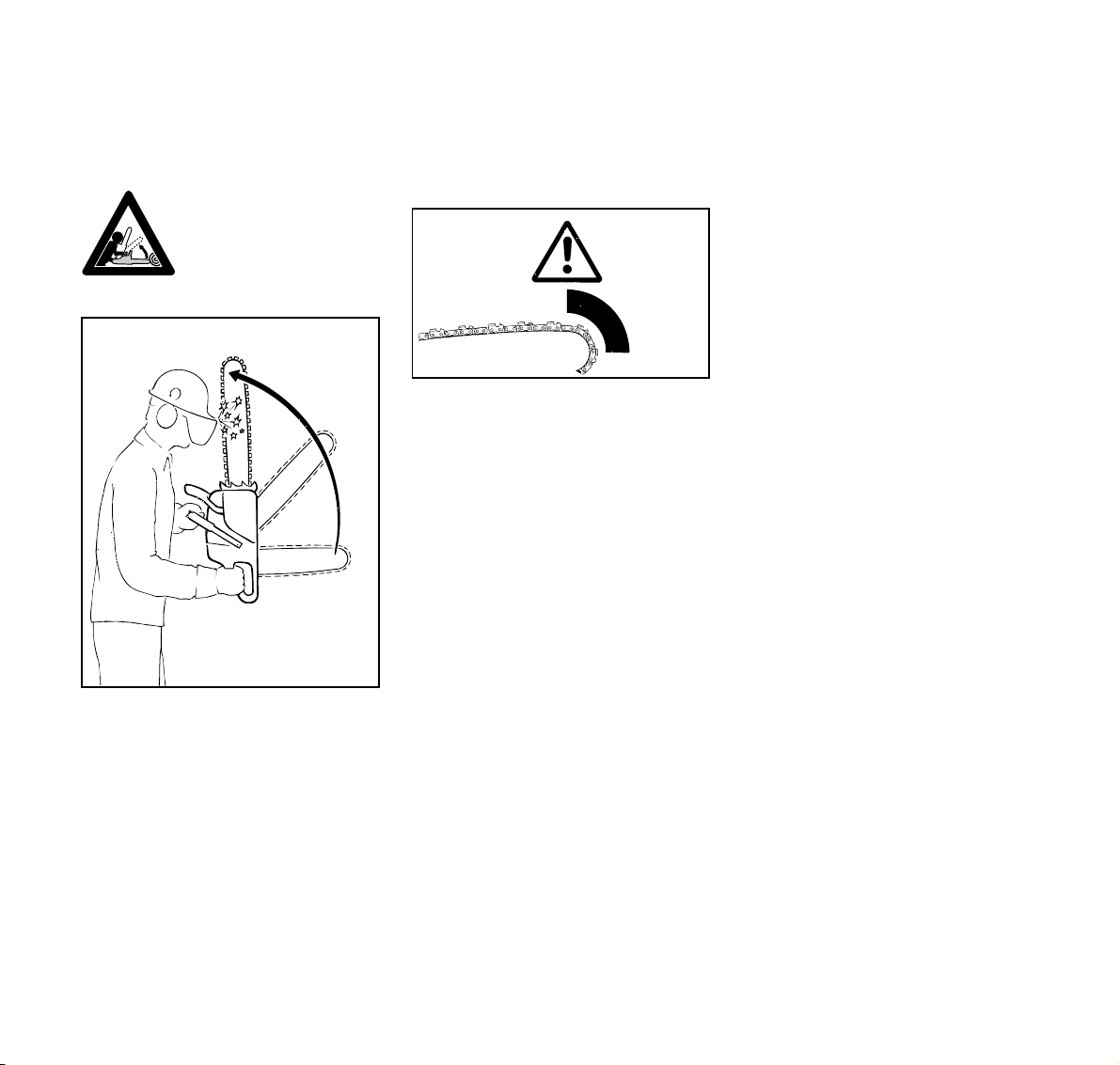
Dangers of kickback
Kickback can result
in serious or fatal
injury.
Kickback causes the the saw to be
suddenly thrown up and back in an
uncontrolled arc towards the operator.
Kickback may occur in the following
situations
– when the upper quadrant of the bar
nose unintentionally contacts wood
or another solid object, e.g. another
limb during limbing,
– when the chain at the nose of the
guide bar is pinched in the cut.
Quickstop chain brake
This device reduces the risk of injury in
certain situations – it cannot prevent
kickback. If activated, the brake stops
the saw chain within a fraction of a
001BA036 KN
second – for a description of this device
refer to "Chain Brake" chapter in this
manual.
To reduce the risk of kickback
– Work cautiously using proper
cutting techniques.
– Hold the chainsaw firmly with both
hands and maintain a secure grip.
– Always cut at full throttle.
– Be aware of the location of the guide
bar nose at all times.
– Do not cut with the bar nose.
001BA093 LÄ
– Take special care with small, tough
limbs, they may catch the chain.
– Never cut several limbs at once.
– Do not overreach.
– Never cut above shoulder height.
7MS 380
Page 8

English
– Do not attempt plunge cuts if you
are not experience in this cutting
technique.
– Be wary of position of log and forces
that may cause the cut to close and
pinch the chain.
– Always cut with a correctly
sharpened, properly tensioned
chain – the depth gauge setting
must not be too large.
Use reduced kickback chain and a guide
bar with a narrow radius nose.
Vibrations
Prolonged use of the unit may result in
vibration-induced circulation problems in
the hands (whitefinger disease).
No general recommendation can be
given for the length of usage because it
depends on several factors.
The period of usage is prolonged by:
– Hand protection (wearing warm
gloves)
–breaks
The period of usage is shortened by:
– Any personal tendency to suffer
from poor circulation (symptoms:
frequently cold fingers, itching).
– Low outside temperatures.
– Gripping force (a tight grip hinders
circulation).
Continual and regular users should
monitor closely the condition of their
hands and fingers. If any of the above
symptoms appear, seek medical advice.
Maintenance and Repairs
Service the machine regularly. Do not
attempt any maintenance or repair work
not described in your owner's manual.
Have all other worked performed by your
STIHL dealer. Only use genuine STlHL
replacement parts. Never modify your
machine in any way as this could result
in serious injury.
Always shut off the engine
– before checking chain tension.
– before retensioning the chain.
– before replacing the chain.
– before rectifying problems.
Check the chain catcher –
and replace it if damaged.
Observe sharpening instructions
for safe and correct handling of saw
chain and guide bar.
Keep the chain in good condition at all
times. It must be properly sharpened,
tensioned and well lubricated.
8
MS 380
Page 9

Using the Saw
English
Always change the chain, guide bar and
sprocket in good time.
Check condition of clutch drum
periodically.
Check the fuel tank for leaks at short
regular intervals.
Do not touch a hot muffler. Check
condition of muffler at regular intervals to
reduce the risk of fires and damage to
hearing. Do not operate your machine if
the muffler is damaged or missing.
Use only a spark plug of the type
approved by STIHL and make sure it is
in good condition (see chapter
“Specifications”). Inspect ignition lead
(insulation in good condition, secure
connection).
To reduce the risk of fire and burn injury
as a result of sparking outside the
cylinder, move the stop switch to STOP
before turning the engine over on the
starter with the spark plug boot removed
or the spark plug unscrewed.
Store fuel and chain lubricant in properly
labelled, safety-type canisters only. Take
care when handling gasoline. Avoid
direct contact with the skin and avoid
inhaling fuel vapour.
To reduce the risk of injury, shut down
your chainsaw immediately in the event
of a chain brake malfunction.
Take the saw to your STIHL dealer. Do
not use your chainsaw until the fault has
been fixed (see chapter “Chain Brake”).
Cutting
Use your saw for cutting wood or
wooden objects only.
Do not operate your chainsaw with the
starting throttle lock engaged. Engine
speed cannot be controlled with the
throttle trigger in this position.
Work calmly and carefully – in daylight
conditions and only when visibility is
good – ensure you do not endanger
others – stay alert at all times.
Use the shortest possible guide bar: The
chain, guide bar and chain sprocket
must match each other and your saw.
001BA087 LÄ
Always hold your saw firmly with both
hands - right hand on the rear handle,
even if you are left-handed. To ensure
safe control, wrap your fingers tightly
around the front handle and control
handle.
9MS 380
Page 10
English
Run the engine at full throttle, engage
the spiked bumper firmly in the wood
and then start cutting.
Never work without the spiked bumper –
the saw may pull you forwards and off
balance.
Position the saw so that your body is
clear of the cutting attachment.
Always pull the saw out of the cut with
the chain running.
Use your saw for cutting only. It is not
designed for prying or shoveling away
limbs, roots or other objects.
Do not underbuck freely hanging limbs.
Take special care when cutting
shattered wood – sharp slivers of wood
may be caught and flung in your
direction.
Make sure your saw does not touch any
foreign materials:
Stones, nails, etc. may be flung off,
damage the saw chain or cause the saw
to kick back unexpectedly.
001BA082 KN
If on a slope, stand on the uphill side or
to one side of the log. Watch out for
rolling logs.
When working at heights:
– Always use a lift bucket.
– Never work on a ladder.
– Never work in a tree.
– Never work on any insecure
support.
– Do not work above shoulder height.
– Never operate the saw with one
hand.
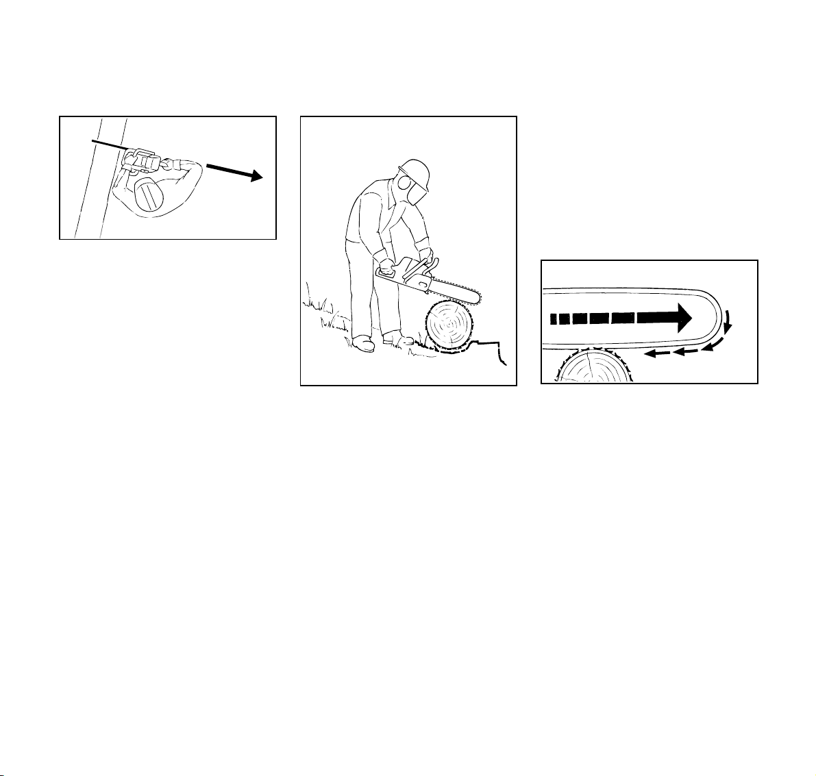
A = Pull-in
001BA033 KN
Pull-in occurs when the chain on the
bottom of the bar is suddenly pinched,
caught or encounters a foreign object in
the wood. The reaction of the chain pulls
the saw forward. Always hold the
spiked bumper securely against the
tree or limb.
A
001BA037 KN
10
MS 380
Page 11
English
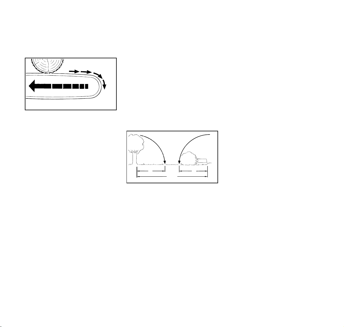
B = Pushback
B
Pushback occurs when the chain on the
top of the bar is suddenly pinched,
caught or encounters a foreign object in
the wood. The reaction of the chain
drives the saw straight back toward the
operator.
Felling and limbing
Do not attempt felling or limbing unless
you have been trained in the necessary
techniques.
Observe local regulations on felling
techniques.
Bystanders must not be allowed in the
felling area – other than helpers.
001BA038 KN
Make sure no-one is endangered by the
falling tree – the noise of your engine
may drown any warning calls.
1
1 1
Maintain a distance of at least 21/2 tree
lengths from next felling site.
/
2
1
/
2
2
Determine direction of fall and
escape paths
Select a clearing into which the tree can
fall.
Pay special attention to the following
points:
– The natural lean of the tree.
– Any unusually heavy limb structure,
damage to tree.
– The wind direction and speed – do
not fell in high winds.
– Direction of slope.
– Neighboring trees.
– Snow load.
– Check the general condition of the
tree. Take particular care with dry or
damaged trees (decayed or rotted).
001BA088 LÄ
11MS 380
Page 12
English
B
45°
A
45°
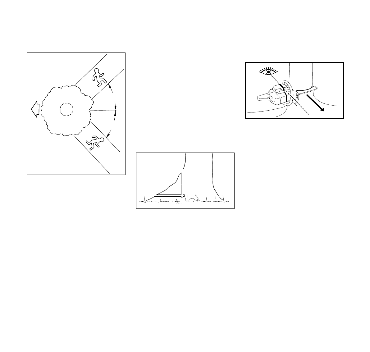
B
A = Direction of fall
B = Escape paths
– Establish paths of escape for
everyone concerned – opposite to
direction of fall at about 45°.
– Remove all obstacles from escape
paths.
– Place all tools and equipment a safe
distance away from the tree, but not
on the escape paths.
– Always keep to the side of the falling
tree. When the tree starts to fall,
withdraw the bar, shut off the engine
and walk away on the preplanned
escape path.
– On steep slopes, prepare escape
paths parallel to the slope.
– Watch out for falling limbs and pay
attention to crown.
Preparing work area at base of tree
– First clear the tree base and work
area from interfering limbs and
brush – safe footing for all persons
concerned.
– Clean lower portion of tree base
with an axe. Sand, stones and other
foreign objects will dull the saw
chain.
001BA040 KN
– Remove large buttress roots: Make
vertical cut first, then horizontal –
but only if tree is in sound condition.
Making felling notch
When making the felling notch, make
use of the gunning sight on the shroud
and fan housing to check the planned
direction of fall.
Position your saw so that the gunning
sight points in exactly in the direction
you want the tree to fall.
There are several permissible ways of
making the horizontal and angled cuts –
observe country-specific regulations on
felling techniques.
001BA146 KN
STIHL recommends the following
sequence:
001BA153 KN
12
MS 380
Page 13
English
C
C
C = Felling notch determines the
direction of fall
: Make the horizontal cut – check the
direction of fall with the gunning
sight.
: Make top cut at an angle of about
45°.
: Check the felling notch and correct it
if necessary.
Important points:
– Felling notch at a right angle to
planned direction of fall.
– As close as possible to the ground.
1
– Cut to a depth of about
the trunk diameter.
/5 to 1/3 of
001BA143 KN
Sapwood cuts
Sapwood cuts help prevent long-fibered
wood splintering when the tree falls.
Apply the cuts at both sides of the trunk
at the same height as the bottom of the
felling notch, to a depth of about
the trunk diameter. On large diameter
trees, cut to no more than the width of
the guide bar.
Do not use sapwood cuts on diseased
trees.
1
/10 of
D
001BA150 KN
Felling cut
Shout a warning before starting the
felling cut.
– Make the felling cut (D) slightly
higher than bottom of felling notch.
– Cut horizontally.
– Leave approx.
uncut. This is the hinge.
1
/10 of tree diameter
D
001BA144 KN
13MS 380
Page 14
English
E
1
E
Drive wedges into the felling cut in good
time – use only wooden, aluminum or
plastic wedges – never steel, which can
damage the chain and cause kickback.
– The hinge (E) helps control the
falling tree.
– Do not cut through the hinge – you
could lose control of the direction of
fall – this could result in an accident.
14
001BA145 KN
– If the trunk is rotten, leave a wider
hinge.
Shout a warning immediately before the
tree falls.
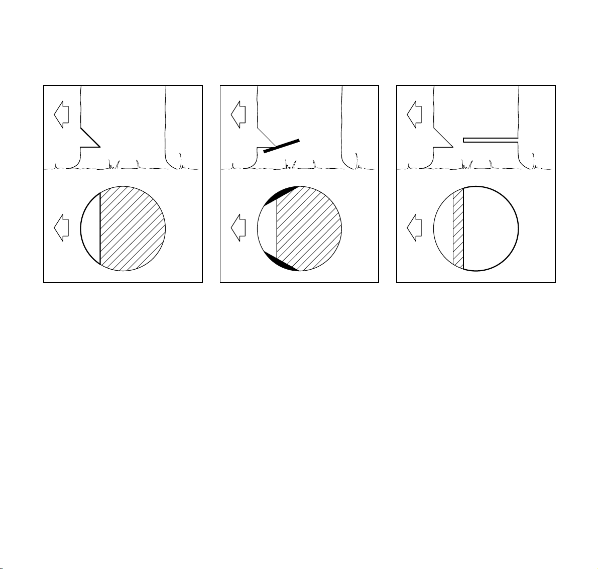
Small diameter trees:
simple fan cut
Apply the spiked bumper behind the
hinge – pivot the saw around this point –
only as far as the hinge. The spiked
bumper rolls against the trunk.
001BA147 KN
Large diameter trees:
sectioning method
If the diameter is greater than the length
of the guide bar, use the sectioning
method.
Use the spiked bumper as a pivot –
avoid repositioning the saw more than
necessary.
First cut (1):
Nose of guide bar should enter wood
just behind the hinge – hold the saw
horizontally and swing it as far as
possible.
001BA148 KN
MS 380
Page 15
English
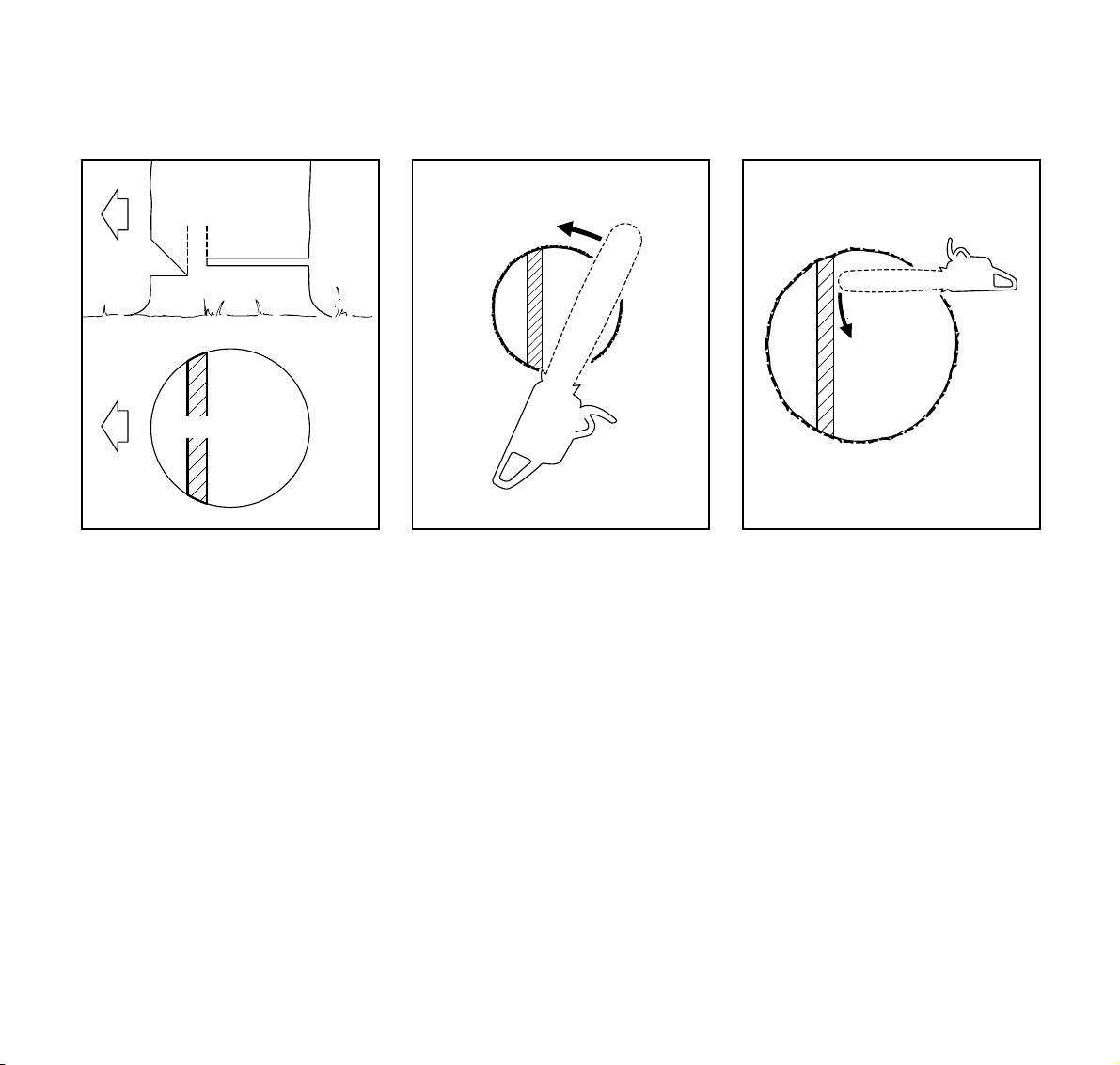
2
3
When repositioning for the next cut (2),
keep the guide bar fully engaged in the
kerf to keep felling cut straight – apply
the spiked bumper.
Last cut (3):
Apply the spiked bumper as for the
simple fan cut.
Do not cut through the hinge!
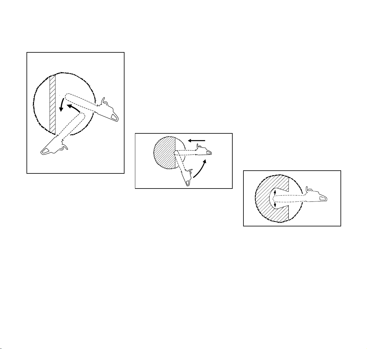
Plunge-cutting
Do not attempt plunge-cutting unless
you are experienced in this cutting
technique.
– Use a low kickback chain and be
extremely cautious.
– For heartwood cut.
– For felling leaners.
– For relieving cuts during bucking.
– For DIY projects.
001BA149 KN
5
4
Begin cut by applying lower portion of
the guide bar nose (4) – do not use
upper portion because of risk of
kickback. Cut until depth of kerf is twice
the width of the guide bar.
Swing saw slowly (5) into plunge-cutting
position. Take care because of the risk
of kickback or pushback.
Heartwood cut
Perform heartwood cut
– if tree diameter is more than twice
the length of the guide bar.
– if a large portion of heartwood
remains uncut on large diameter
trees.
– on trees that are difficult to fell (oak,
beech), to prevent heartwood
splintering and maintain planned
direction of fall.
6
– on soft deciduous trees to relieve
tension in lying log and prevent
slivers in the center of the hinge
being torn out of the log.
001BA154 KN
001BA089 LÄ
: Begin plunge cut by inserting the
bar in the felling notch and then
enlarge the cut to both sides.
Make the plunge cut (6) very carefully.
Danger of pushback.
15MS 380
Page 16

English
Exercise extreme caution
– with leaners
– with trees that have fallen
unfavorably between other trees
and are under strain
– when working in blowdown areas.
Do not work with the chainsaw in such
circumstances. Use block and tackle,
cable winch or tractor.
Pull out exposed and cleared logs.
Select clear area for cutting.
Dry or damaged trees (decayed or
rotted) represent a considerable danger
that is difficult or almost impossible to
assess. Use aids such as block and
tackle, cable winch or tractor
When felling in the vicinity of roads,
railways, power lines, etc.
Take extra precautions. If necessary,
inform the police, utility company or
railway authority
Limbing
– Use a low kickback chain.
– Work with the saw supported
wherever possible.
– Do not stand on the log while
limbing.
– Do not work with the bar nose.
– Watch for limbs which are under
tension.
– Never attempt to cut several limbs
at once.
When cutting small logs
– Use a sturdy and stable support –
sawhorse.
– Never hold the log with your leg or
foot.
– Never allow another person to hold
the log or help in any other way.
Lying or standing logs under tension
1
2
001BA151 KN
2
1
001BA152 KN
Always start relieving cut (1) at the
compression side, then perform the
bucking cut (2) at the tension side – the
saw will otherwise pinch or kick back.
If not otherwise possible, make the
bucking cut from the bottom upwards
(underbuck) – be wary of pushback.
16
Lying logs must not touch the ground at
the point where the cut is made –
this will damage the chain.
MS 380
Page 17

Mounting the Bar and Chain
English
1
a
t = a : 2
You can run chains of different pitches
on this chainsaw – depending on the
chain sprocket (see “Specifications”):
The chain pitch (1) must match the pitch
of the sprocket and the guide bar (for
Rollomatic). The drive link gauge (2)
must match the bar groove width (3).
The pitch is marked on the chain
sprocket and guide bar in inches
(e.g. 3/8 or .325). The groove width
is marked on the guide bar in
millimeters (e.g. 1.6).
If non-matching components of the
wrong pitch or drive link gauge are
run together on the same machine
they may be damaged beyond
repair after a short period of
operation.
2
3
001BA105 KN
: Unscrew the nuts and take off the
chain sprocket cover.
4
5
: Turn screw (4) counterclockwise
until the tensioner slide (5) butts
against left end of housing slot.
143BA034 KN
: Disengage the chain brake: Pull
hand guard (6) toward front handle.
001BA107 KN
Wear work gloves to protect your
hands from the sharp cutters.
: Fit the chain – start at the bar nose.
6
001BA108 KN
143BA003 KN
17MS 380
Page 18

English
9
: Fit the guide bar over the studs (7) –
cutting edges on top of bar must
point to right – and engage the
peg of the tensioner slide in locating
hole (8) – place the chain over
sprocket (9) at the same time.
: Now turn tensioning screw (10)
clockwise until there is very little
chain sag on the underside of the
bar – and the drive link tangs are
located in the bar groove.
: Refit the sprocket cover –
and screw on the nuts only fingertight.
: Go to “Tensioning the Saw Chain”.
7
7
10
8
Tensioning the Saw Chain
1
001BA109 KN
Retensioning during cutting work:
: Shut off the engine first –
and then loosen the nuts.
: Hold the bar nose up and use
screwdriver to turn tensioning screw
(1) clockwise until chain fits snugly
against the underside of the bar.
: While still holding the bar nose up,
tighten down the nuts firmly.
: Go to chapter “Checking Chain
Tension”.
A new chain has to be retensioned more
often than one that has been in use for
some time.
: Check chain tension frequently –
see chapter "Operating
Instructions".
Checking Chain Tension
133BA024 KN
: Shut off the engine.
: Wear work gloves.
: Chain must fit snugly against the
underside of the bar – and, with the
chain brake disengaged, it must still
be possible to pull the chain along
the bar by hand.
: If necessary, retension the chain.
A new chain has to be retensioned more
often than one that has been in use for
some time.
Check chain tension frequently – see
"Operating Instructions".
143BA007 KN
18
MS 380
Page 19

Fuel
English
Your engine requires a mixture of
gasoline and engine oil.
The quality of these constituents and the
mix ratio have a decisive influence on
the function and service life of the
engine.
Unsuitable fuels or lubricants or mix
ratios other than those specified
may result in serious damage to the
engine (piston seizure, rapid rate of
wear, etc.).
Gasoline
Use only high-quality mid-grade
gasoline with a minimum octane rating
of 90. If the octane rating of the midgrade gasoline in your area is lower, use
premium fuel – leaded or unleaded.
For health and environmental
reasons, you should give
preference to unleaded gasoline.
If your machine is equipped with a
catalytic converter, you must use
unleaded gasoline.
A few tankfuls of leaded gasoline
will greatly reduce the efficiency of
the catalytic converter.
Engine Oil
Use only quality two-stroke engine oil.
We recommend STIHL two-stroke
engine oil since it is specially
formulated for use in STlHL engines
and guarantees a long engine life.
Use only STIHL 50:1 two-stroke
engine oil for the fuel mix in models with
a catalytic converter.
If no STIHL two-stroke engine oil is
available, use only quality two-stroke oil
designed for use in air cooled engines.
Do not use oils designed for water
cooled engines or engines with a
separate lubricating system (e.g.
conventional four-stroke engines).
Poor quality gasoline or engine oil
may damage the engine, sealing
rings, hoses and the fuel tank.
Mixing Fuel
1
2
MIX
Avoid direct skin contact with
gasoline and avoid inhaling
gasoline vapor.
: Use a canister approved for storing
fuel. Pour oil (1) into the canister
first, then add gasoline (2) and mix
thoroughly.
Mix Ratio
STIHL 50:1 two-stroke engine oil:
50 parts gasoline to 1 part oil
Other high-quality two-stroke engine
oils:
25 parts gasoline to 1 part oil
000BA042 KN
19MS 380
Page 20

English
Fueling
Examples
Gasoline
Liters Liters (cc) Liters (cc)
STIHL
engine oil
50:1
Other
high-quality
TC oils
25:1
1 0.02 (20) 0.04 (40)
5 0.10 (100) 0.20 (200)
10 0.20 (200) 0.40 (400)
15 0.30 (300) 0.60 (600)
20 0.40 (400) 0.80 (800)
25 0.50 (500) 1.00 (1000)
Storing Fuel
Fuel mix ages:
Only mix sufficient fuel for a few months
work. Store in approved safety-type fuel
canisters in a dry and safe location.
: Thoroughly shake the mixture in the
canister before fueling your
machine.
Pressure may build up in the
canister – open it carefully.
: Clean the fuel tank and canister
from time to time.
Dispose of remaining fuel and
cleaning fluid properly in
accordance with local regulations
and environment requirements.
: Before fueling, clean the filler cap
and the area around it to ensure that
no dirt falls into the tank.
: Position the machine so that the
filler cap is facing up.
Take care not to spill fuel while fueling
and do not overfill the tank. The STIHL
filler nozzle* is recommended for this
purpose and also helps you avoid
inhaling fuel vapor.
Opening the cap
001BA159 KN
001BA160 KN
: Raise the grip until it is upright.
001BA161 KN
: Turn the cap counterclockwise
(approx. a quarter turn).
: Remove the filler cap.
20
* see “Guide to Using this Manual“
MS 380
Page 21

Chain Lubricant
English
Closing the cap
: Fit the cap - grip upright -marks
must line up.
: Turn the cap clockwise as far as
stop (approx. a quarter turn).
: Fold the grip flush with the top of the
cap.
If the grip does not lie completely flush
with the cap and the detent on the grip
does not engage the recess in the filler
neck, the cap is not properly seated and
tightened and you must repeat the
above steps.
001BA162 KN001BA163 KN
Change the fuel pickup body once
every year
: Drain the fuel tank.
: Use a hook to pull the fuel pickup
body out of the tank and take it off
the hose.
: Push the new pickup body into the
hose.
: Place the pickup body in the tank.
For automatic and reliable
lubrication of the chain and guide
bar – use only an environmentally
compatible quality chain and bar
lubricant. Rapidly biodegradable
STIHL Bioplus is recommended.
Biological chain oil must be resistant
to aging (e.g. STIHL Bioplus) since
it will otherwise quickly turn to resin.
This results in hard deposits that are
difficult to remove, especially in the
area of the chain drive, clutch and
chain. It may even cause the oil
pump to seize.
The service life of the chain and guide
bar depends on the quality of the
lubricant. It is therefore essential to use
165BA003 KN
only a specially formulated chain
lubricant.
21MS 380
Page 22

English
If special chain lubricant is not available,
you may - in an emergency - use an HD
single grade or multigrade engine oil
with a viscosity that suits the prevailing
outside temperature.
Do not use waste oil!
Medical studies have shown that
renewed contact with waste oil can
cause skin cancer. Moreover, waste
is environmentally harmfull!
Waste oil does not have the
necessary lubricating properties
and is unsuitable for chain
lubrication.
Filling Chain Oil Tank
: Thoroughly clean the oil filler cap
and the area round it to ensure that
no dirt falls into the tank.
: Remove the filler cap.
: Refill the chain oil tank every time
you refuel.
: Close the filler cap.
There must still be a small amount of oil
in the oil tank when the fuel tank is
empty.
If the oil tank is still partly full, the reason
may be a problem in the oil supply
system: Check chain lubrication, clean
the oilways, contact your STlHL dealer
for assistance if necessary.
Checking Chain Lubrication
001BA158 KN
143BA024 KN
The saw chain must always throw off a
small amount of oil.
Never operate your saw without
chain lubrication. If the chain runs
dry, the whole cutting attachment
will be irretrievably damaged within
a very short time.
Always check chain lubrication and
oil level in tank before starting work.
Every new chain has to be broken in for
about 2 to 3 minutes.
After breaking in chain, check chain
tension and adjust if necessary – see
“Checking Chain Tension”.
22
MS 380
Page 23

Chain Brake
Locking chain with chain brake
– in an emergency
– when starting
– at idling speed
The chain is stopped and locked when
the hand guard is pushed toward the bar
nose by the left hand –
or when brake is activated by inertia in
certain kickback situations.
143BA011 KN
Releasing the chain brake
: Pull the hand guard back toward the
front handle.
Always disengage chain brake
before accelerating engine and
before starting cutting work. The
only exception to this rule is when
you check operation of the chain
brake.
High revs with the chain brake
engaged (chain locked) will quickly
damage the powerhead and chain
drive (clutch, chain brake).
The chain brake is also activated by
the inertia of the front hand guard
if the kickback force of the saw is high
enough:
The hand guard is accelerated toward
the bar nose – even if your left hand is
not behind the hand guard, e.g. during
felling cut.
The chain brake will operate only if the
hand guard has not been modified in any
way.
Check operation of chain brake
Before starting work:
Run engine at idle speed, engage the
chain brake (push hand guard toward
143BA012 KN
bar nose). Accelerate up to full throttle
for no more than 3 seconds – the chain
must not rotate. The hand guard must be
free from dirt and move freely.
English
23MS 380
Page 24

English
Chain brake maintenance
The chain brake is subject to normal
wear. It is necessary to have it serviced
and maintained regularly by trained
personnel, such as your STIHL servicing
dealer, at the following intervals:
Full-time professional
users: every 3
months
Semi-professional
users (in agriculture
and construction): every 6
months
Hobby and
occasional users: every 12
months
Information Before You Start
1
2
3
4
The four positions of the
Master Control lever
1 = Engine off –
ignition is switched off
2 = Normal run position –
engine runs or can fire
To move the Master Control lever from 2
to 3 or 4, press down the throttle trigger
interlock and squeeze throttle trigger at
the same time.
3 = Warm start – this position is used to
start a warm engine. The Master
Control lever moves to the normal
run position as soon as the throttle
trigger is squeezed.
4 = Cold start – this position is used to
start a cold engine.
Starting / Stopping the Engine
1
215BA001 KN
: Observe safety precautions – see
chapter on "Safety Precautions".
: Push hand guard (1) forward:
The chain is now locked.
Press down trigger interlock (2) and
squeeze throttle trigger (3) at the
same time.
Set the Master Control to:
Position 4 if engine is cold.
Position 5 if engine is warm
(also use position 5 if the engine has
been running but is still cold)
5
4
2
3
215BA002 KN
24
MS 380
Page 25

English
: Place your saw on the ground.
: Make sure you have a firm footing –
check that chain is not touching any
object or the ground.
Bystanders must be well clear of the
general work area of the saw.
: Hold the saw firmly on the ground
with your left hand on the front
handle – your thumb should be
under the handlebar.
: Put your right foot into the rear
handle and press down.
143BA018 KN
Alternative method of starting:
: Hold the rear handle tightly between
your legs, just above the knees.
: Hold the front handle firmly with
your left hand – your thumb should
be under the handlebar.
143BA019 KN
: Pull the starter grip slowly with your
right hand until you feel it engage –
then give the grip a brisk strong pull
and push down the front handle at
the same time.
Do not pull out the starter rope all
the way – it might otherwise break.
: Do not let the starter grip snap back
– guide it slowly and vertically into
the housing so that the starter rope
can rewind properly.
If the engine is new, pull the starter
several times to prime the fuel system.
143BA020 KN
25MS 380
Page 26

English
At very low outside temperatures:
: Allow engine to warm up at part
throttle.
9
5
7
8
When engine begins to fire:
: Move Master Control lever (7) to
position 5 and continue cranking.
: As soon as engine runs,
immediately blip the throttle trigger
(8) – the Master Control lever (7) will
move to the run position 9 and the
engine will settle down to idling
speed.
.
As the chain brake is still engaged,
the engine must be returned to
idling speed immediately – or the
engine and chain brake might
otherwise be damaged.
215BA003 KN
: Pull the hand guard back toward
the front handle:=
The chain brake is now disengaged
– your saw is ready for operation.
Always disengage the chain brake
before accelerating the engine.
High revs with the chain brake
engaged (chain locked) will quickly
damage the powerhead and chain
drive (clutch, chain brake).
: Observe safety precautions.
: Always check operation of chain
lubrication before starting work.
To shut down the engine:
: Move Master Control lever to c
If fuel tank has been run until dry
and then refueled:
: Pull starter rope several times until
fuel system is primed.
: Now start the engine.
143BA012 KN
26
MS 380
Page 27

Operating Instructions
English
If the engine doesn’t start:
If you did not move the Master Control
lever to the "warm start" position quickly
enough after the engine began to fire,
the combustion chamber has flooded.
11
10
7
: Move Master Control (7) to run
position.
: Loosen knob (10) in direction of
arrow.
: Remove carburetor box cover (11).
: Pull off the spark plug boot.
: Unscrew and dry off the spark plug.
: Set the Master Control lever to c
: Press down the trigger interlock
lever – open the throttle wide and
crank the engine several times with
the starter to clear the combustion
chamber.
: Install the spark plug and connect
the spark plug boot (press it down
firmly) – refit carburetor box cover.
: Set Master Control lever to warm
215BA004 KN
start position – even if engine is
cold.
: Now start the engine.
During break-in period
A factory new machine should not be run
at high revs (full throttle off load) for the
first three tank fillings. This avoids
unnecessary high loads during the
break-in period. As all moving parts
have to bed in during the break-in
period, the frictional resistances in the
215BA005 KN
engine are greater during this period.
The engine develops its maximum
power after about 5 to 15 tank fillings.
Do not make the mixture leaner to
achieve an apparent increase in
power – this could damage the
engine – see “Adjusting
Carburetor”.
Always disengage the chain brake
before opening the throttle. Running
the engine at higher revs with the
chain brake engaged (saw chain at
a standstill) will quickly damage the
engine and chain drive (clutch,
chain brake).
27MS 380
Page 28

English
Oil Quantity Control *
During operation
Check chain tension frequently
A new chain has to be retensioned more
often than one that has been in use for
some time.
Chain cold:
Tension is correct when chain fits snugly
against the underside of the bar and can
still be pulled along the bar by hand.
Retension if necessary – see
“Tensioning the Saw Chain”.
Chain at operating temperature:
The chain stretches and begins to sag.
The drive links must not come out of the
bar groove – the chain may otherwise
jump off the bar.
Retension the chain – see “Tensioning
the Saw Chain”!
Always slacken off the chain after
finishing work. The chain contracts
as it cools down. If it is not
slackened off, it can damage the
crankshaft and bearings.
After long period of full-throttle
operation
Allow engine to run for a short while at
idle speed so that engine heat can be
dissipated by flow of cooling air. This
protects engine-mounted components
(ignition, carburetor) from thermal
overload.
After finishing work
: Slacken off the chain if you have
retensioned it at operating
temperature during cutting work.
The chain contracts as it cools
down. If it is not slackened off, it
could damage the crankshaft and
bearings.
Storing your saw for a short period:
Wait for engine to cool down. To avoid
condensation, fill the fuel tank and keep
the machine in a dry place, well away
from sources of ignition, until you need it
again.
Storing for a long period:
See “Storing the Unit”!
1
001BA157 KN
Different quantities of oil are required for
different bar lengths, types of wood and
cutting techniques.
: Use the adjusting screw (1) (on
underside of machine) to vary the
oil feed rate as required.
: E = Ematic position, medium oil flow
rate - turn adjusting screw to "E"
(Ematic position)
: To increase oil feed – turn adjusting
screw clockwise.
: To reduce oil feed – turn adjusting
screw counter-clockwise.
Your chain must always be wetted
with a film of lubricant.
28
* Special accessory
MS 380
Page 29

English
Taking Care of Guide Bar
2
1
: Turn the bar over –
every time you sharpen the chain
and every time you replace the
chain – this helps avoid one-sided
wear, especially at the nose and
underside of the bar.
: Regularly clean
the oil inlet hole (1),
the oilway (2) and
the bar groove (3).
: Measure groove depth –
with scale on filing gauge* – in area
used most for cutting.
3
3
Chain
type
Picco 3/8" P 5.0 mm
Rapid 1/4" 4.0 mm
Rapid 3/8"; 0.325" 6.0 mm
Rapid 0.404" 7.0 mm
If groove depth is less than specified:
: Replace the guide bar.
The drive link tangs will otherwise
scrape along the bottom of the groove –
the cutters and tie straps will not ride on
the bar rails.
001BA119 KN
Pitch Minimum
groove
depth
Cleaning the Air Filter
3
2
1
215BA006 KN
Dirty air filters reduce engine power,
increase fuel consumption and make
starting more difficult.
If there is a noticeable loss of
engine power
: Move the Master Control lever (1)
to the normal run position.
: Loosen knob (2) in direction of
arrow.
: Remove the carburetor box
cover (3).
: Clean away loose dirt from around
the filter.
* see “Guide to Using this Manual”
29MS 380
Page 30

English
Adjusting the Carburetor
5
4
7
6
: Unscrew the slotted nuts (4).
: Remove the filter (5) and separate
the two halves of the filter.
: Take out the screw (6) in the
carburtetor box cover and remove
the prefilter (7).
: Knock the filter out on the palm of
your hand or blow it clear with
compressed air from the inside
outwards.
In case of stubborn dirt:
: Wash the filter components in
STIHL universal cleaner or a clean,
non-flammable solution (e.g. warm
soapy water) and then dry.
: Always replace a damaged filter.
215BA007 KN
: Reassemble the filter components.
215BA008 KN
: Make sure the choke shutter (8) and
torsion spring are properly seated:
The hook of the torsion spring (9)
must engage the slot (arrow).
: Secure the main filter and prefilter in
position.
: Fit the carburetor box cover.
General Information
Your carburetor comes from the factory
with a standard setting.
This is the optimum setting under the
barometric pressure and climatic
conditions at the factory.
It ensures your machine will deliver
maximum power, be fuel efficient and
operate reliably.
Retuning may be necessary if there is a
change in barometric pressure (weather,
altitude), temperature or humidity.
Adjustment of the high speed screw
changes the power output and
maximum RPM of the engine when it is
running off load.
If the mixture is made too lean
there is a risk of engine damage
due to insufficient lubrication and
overheating.
Do not use a brush to clean the
fleece filter.
30
MS 380
Page 31

English
Standard Setting
(without tachometer)
H
L
: Shut off the engine.
: Check the air filter and clean or
replace it if necessary.
: Carefully screw both adjusting
screws down onto their seats
(clockwise).
: Open high speed screw (H) one full
turn.
: Open the low speed screw (L) one
full turn.
If you do not have a tachometer, do
not set the high speed screw any
leaner by turning it beyond the
standard setting.
Fine Tuning
(with tachometer)
: Check the air filter and clean or
replace it if necessary.
: Check chain tension.
: Start the engine and run until it is
warm.
: Adjust idle speed correctly (chain
215BA010 KN
must not rotate).
: Starting from the standard setting,
use the high speed screw (H) to
adjust the maximum engine speed
with a tachometer to 12,500 rpm
(with bar and properly tensioned
chain).
If the mixture is made too lean
there is a risk of engine damage
due to insufficient lubrication and
overheating.
Adjusting Idle Speed
L
Engine stops while idling
: Open the low speed screw (L) one
full turn.
: Turn the idle speed screw (LA)
clockwise until chain begins to run –
then turn it back one quarter of a
turn.
Chain runs when engine is idling
: Open the low speed screw (L) one
full turn.
: Turn the idle speed screw (LA)
counterclockwise until chain stops
running – then turn screw another
quarter turn in the same direction.
215BA011 KN
31MS 380
Page 32

English
Checking the Spark Plug
Erratic idling behavior, poor
acceleration
(even though the low speed screw is
opened one turn)
Idle setting is too lean.
: Turn the low speed screw (L)
counterclockwise until engine
runs and accelerates smoothly.
It is usually necessary to change the
setting of the idle speed screw (LA)
after every correction to the low speed
screw (L).
If engine is down on power, difficult to
start or runs poorly at idle speed, first
check the spark plug.
: Remove the spark plug –
see "Starting / Stopping the Engine".
: Clean dirty spark plug.
: Check electrode gap (A) and
readjust if necessary – see
"Specifications".
: Rectify the problems which have
caused fouling of spark plug:
– To much oil in fuel mix.
– Dirty air filter.
– Unfavorable running conditions.
: Fit a new spark plug after
about 100 operating hours – or
sooner if the electrodes are badly
eroded.
Install only suppressed spark plugs
of the type approved by STIHL –
see "Specifications".
To reduce the risk of arcing
and fire:
000BA002 KN
1
000BA045 KN
: If the spark plug comes with a
detachable adapter nut (1), screw it
on firmly.
32
MS 380
Page 33

English
Spark Arresting Screen in Muffler*
3
6
7
2
2
1
4
5
3
On all spark plugs:
: Always press the boot (2) firmly on
to the spark plug (3).
: If the engine is down on power,
check the spark arresting screen in
the muffler.
: Wait for the muffler to cool down.
: Take out the screw (1).
: Remove the spark arresting
000BA050 KN
screen (2).
: Clean the spark arresting screen.
If the screen is damaged or heavily
carbonized, fit a new one.
: Take out the screws (3).
: Remove muffler upper casing (4).
3
215BA015 KN
: Remove the screw (5) inside the
upper casing.
: Bend back the retaining tabs (6)
and pull out the spark arresting
screen (7).
: Clean the spark arresting screen.
If the screen is damaged or heavily
carbonized, fit a new one.
: Install the spark arresting screen in
the reverse sequence.
215BA024 KN
* see "Guide to Using this Manual"
33MS 380
Page 34

English
Replacing Starter Rope and Rewind Spring
1
1
1
: Remove the screws (1).
: Lift the fan housing from the
crankcase and pull it away to
sideways.
2
3
4
: Use a screwdriver or suitable pliers
to carefully remove the spring clip
(2) from the starter post.
: Carefully remove the rope rotor with
washer (3) and pawl (4).
The rewind spring may pop out
during this procedure – take care to
avoid injury.
5
215BA012 KN
6
: Use a screwdriver to pry the rope (5)
out of the starter grip.
215BA013 KN
: Remove the remaining rope from
the rotor and grip, making sure the
sleeve is not pushed out of the grip.
: Thread the new rope through the
top of the starter grip and guide
bushing (6).
: Pull the rope through the rotor and
secure it with a simple overhand
knot.
2
3
4
: Coat rope rotor bearing bore with
resin-free oil.
: Slip rotor over the starter post – turn
it back and forth to engage anchor
loop of the rewind spring.
: Fit the pawl (4) in the rope rotor.
: Fit the washer (3) on the starter
215TI014 KN
post.
: Use a screwdriver or suitable pliers
to install the spring clip (2) on the
starter post and engage it on the
pawl’s peg – the spring clip must
point clockwise as shown in the
illustration.
215BA013 KN
34
MS 380
Page 35

English
Tensioning the Rewind Spring
: Make a loop in the unwound starter
rope and use it to turn the rope rotor
seven full revolutions in the
direction of the arrow.
: Hold the rotor steady – pull out and
straighten the twisted rope.
: Release the rope rotor.
: Let go of rope slowly so that it winds
onto the rotor.
The starter grip must locate firmly in the
rope guide bushing. If the grip droops to
one side: Increase spring tension by
adding one more turn.
When the starter rope is fully extended it
must still be possible to rotate the rotor
another half turn. If this is not the case,
the spring is overtensioned and could
break.
Replacing a Broken Rewind
Spring
: Remove the rope rotor.
: Remove the spring housing and
parts of the spring.
The bits of spring might still be
under tension and could fly apart
215BA016 KN
when you take them out of the fan
cover. To reduce risk of injury, wear
eye and face protection and work
gloves.
: Use a screwdriver to carefully
remove the parts of the spring.
: Lubricate the new spring with a few
drops of non-resinous oil.
215BA017 KN
: Fit the new spring housing – bottom
plate must face up – engage outer
spring loop on lug.
: Refit the rope rotor.
: Tension the rewind spring.
: Refit the fan housing and tighten it
down firmly.
: If the spring pops out of the housing
during installation: Refit it in the
counterclockwise direction, starting
outside and working inwards.
: Take one turn of rope off the rotor in
such a case.
35MS 380
Page 36

English
Storing the Machine Checking and Replacing
Chain Sprocket
For periods of about 3 months or longer:
: Drain and clean the fuel tank in a
well ventilated area.
: Run engine until carburetor is dry,
this helps prevent the carburetor
diaphragms sticking together.
: Remove the saw chain and guide
bar, clean them and spray with
corrosion inhibiting oil.
: Thoroughly clean the unit,
pay special attention to the cylinder
fins and air filter.
: If you use a biological chain and bar
lubricant, e.g. STIHL BioPlus,
completely fill the chain oil tank.
: Store the unit in a dry and high or
locked location, out of the reach of
children and other unauthorized
persons.
: Remove the chain sprocket cover,
chain and guide bar.
: Disengage the chain brake:
Pull hand guard toward the front
handle.
Replacing the Chain Sprocket
– Replace the chain sprocket after
using two Oilomatic chains.
– Replace sooner if the wear marks
on the sprocket are deeper than
approx. 0.5 mm since this would
reduce the life of the chain. You can
use a reference gauge (Special
Accessories) to check the depth of
the wear marks on sprockets.
It is best to use two chains in
rotation with one sprocket.
Use only original STIHL chain sprockets
to ensure correct operation of the chain
brake.
Rim Sprocket
: Use a screwdriver to remove
the E-clip (1).
: Take off the washer (2).
: Examine the splines on the clutch
001BA121 KN
drum – if wear marks are severe,
install a new clutch drum.
: Replace the rim sprocket (3)
with cavities facing outward.
: Refit the washer and E-clip on the
crankshaft.
36
MS 380
Page 37

English
Spur Sprocket, Clutch Drum
7
5
6
8
4
5
: Use a screwdriver to remove
the E-clip (1).
: Take off the washer (2).
: Use circlip pliers (Special
Accessories) to remove the
circlip (4).
: Take out the screws (5).
: Remove the side plate (6) and
cover (7) with cover washer (8).
2
1
10
12
11
215BA019 KN
: Remove the oil pump drive worm (9)
by rotating it clockwise while pulling
it off the pump shaft.
: Remove the spur sprocket or clutch
drum (10) with sprocket, spur gear
(11) and needle cage (12) from the
crankshaft.
Check serviceability of spur gear
and worm. Replace any worn or
damaged parts.
Install in the reverse sequence:
: Clean the stub of the crankshaft and
needle cage and lubricate with
STlHL grease (Special
Accessories).
: Push the needle cage, spur
9
215BA020 KN
sprocket and clutch drum with spur
gear onto the crankshaft.
: Engage the oil pump drive worm by
rotating it counterclockwise while
pushing it onto the pump shaft.
: Lubricate the worm and spur gear
with STlHL grease (Special
Accessories).
: Fit the cover, cover washer and side
plate, fit screws and tighten down
firmly.
: Install the circlip on the spur
sprocket – each end of the ring must
locate on the top of a tooth.
: Replace the rim sprocket (3)
with cavities facing outward.
: Fit the washer and E-clip on the
crankshaft.
37MS 380
Page 38

English
Maintaining and Sharpening Saw Chain
Correctly sharpened chain
A properly sharpened chain slices
through wood effortlessly and requires
very little feed pressure.
Do not work with a dull or damaged
chain as it will increase the physical
effort required, produce unsatisfactory
results and a higher rate of wear.
: Clean the chain.
Check the chain
:
links and damaged rivets.
: Replace any damaged or worn parts
of the chain and match the new
parts to the shape and size of the
original parts.
It is absolutely essential to comply
with the angles and dimensions
specified below. If the saw chain is
incorrectly sharpened – and in
particular if the depth gauge is set
too low – there is a risk of increased
kickback of the chainsaw, with
resulting risk of injury.
for cracks in the
3/8
3
The chain pitch (e.g.
the depth gauge end of each cutter.
Use only special saw chain
sharpening files. Other files have the
wrong shape and cut.
Select file diameter according to chain
pitch – see table “Sharpening Tools”.
You must observe certain angles when
resharpening the chain cutter.
/8") is marked on
A
B
689BA020 KN
A = Filing angle
B = Side plate angle
Chain type Angle (°)
Rapid-Micro (RM) 30 85
Rapid-Super (RS) 30 60
Picco-Micro (PM/PMN) 30 85
Cutter shapes:
Micro = Semi-chisel
Super = Full chisel
The specified angles A and B are
obtained automatically if the
recommended files or sharpening tools
and correct settings are used.
689BA021 KN
AB
38
MS 380
Page 39

English
Furthermore, the angles must be the
same on all cutters. If angles are
uneven: Chain will run roughly, not in a
straight line, wear quickly and finally
break.
As these requirements can be met only
after sufficient and constant practice:
: Use a file holder*
A file holder must be used for manual
resharpening (see table "Sharpening
Tools"). The correct filing angles are
marked on the file holder.
For checking angles
90°
85°70°
80°
60°
35°
30°
0°
10°
Use a STlHL filing gauge* (see table
"Sharpening Tools"). This is a universal
689BA025 KN
tool for checking the filing and side plate
angles, depth gauge setting and cutter
length. It also cleans the guide bar
groove and oil inlet holes.
File correctly
: Select sharpening tools according
to chain pitch.
: Clamp the bar in a vise if necessary.
: Lock the chain – push hand guard
forward.
: To rotate the chain – pull hand guard
against handle.
: Sharpen chain frequently, take
away as little metal as possible –
two or three strokes of the file are
usually enough.
90°
689BA018 KN
689BA022 KN
689BA043 KN
: Hold the file horizontally (at right
angle to side of guide bar) and file
according to the angles marked on
the file holder. Rest the file holder on
the top plate and depth gauge.
* see “Guide to Using this Manual”
* see “Guide to Using this Manual”
39MS 380
Page 40

English
: Always file from the inside to the
outside of the cutter.
: The file only sharpens on the
forward stroke –
lift the file off the cutter on the
backstroke.
: Avoid touching the tie straps and
drive links with the file.
: Rotate the file at regular intervals
while filing to avoid one-sided wear.
: Use a piece of hardwood to remove
burrs from cutting edge.
: Check angles with the filing gauge.
All cutters must be the same length.
If the cutters are not the same length,
they will have different heights. This
makes the chain run roughly and can
cause it to break.
: Find the shortest cutter and then file
all other cutters back to the same
length. This can be very time
consuming – it is best to have it
done in the workshop on an electric
grinder.
Depth gauge setting
a
The depth gauge determines the height
at which the cutter enters the wood and
thus the thickness of the chip removed.
Specified distance or setting between
depth gauge and cutting edge = a:
This setting may be increased by 0.2mm
(0.008") for cutting softwood in mild
weather season – no frost.
Chain pitch Depth gauge
setting “a“
Inch (mm) mm (inch)
1
/
4
3
/8 PMN (9.32) 0.45 (0.018)
3
/8 PM (9.32) 0.65 (0.026)
0.325 (8.25) 0.65 (0.026)
3
/
8
0.404 (10.26) 0.80 (0.031)
(6.35) 0.65 (0.026)
(9.32) 0.65 (0.026)
Lowering depth gauges
The depth gauge setting is reduced
when the chain is sharpened.
: Use a filing gauge to check the
setting every time you sharpen the
chain.
689BA023 KN
1
689BA047 KN
: Place a filing gauge (1) that
matches the chain pitch on the
chain – if the depth gauge projects
from the filing gauge, the depth
gauge has to be lowered.
40
689BA051 KN
: File down the depth gauge until it is
level with the filing gauge.
MS 380
Page 41

English
On PM1 and RM2 chains the rear
hump of the tie strap (with service
marking) is lowered along with the
depth gauge. The other parts of the
triple-humped tie strap must not be
filed since this may increase the
kickback tendency of the chainsaw.
689BA044 KN
689BA052 KN
: After sharpening, clean the chain
: File the top of the depth gauge
parallel to the stamped service
marking (see arrow) – but do not
lower the highest point of the depth
gauge in this process.
The kickback tendency of the
: Place filing gauge on the chain –
highest point of depth gauge must
be level with the filing gauge.
thoroughly, remove filings or
grinding dust – lubricate the chain
thoroughly.
: Before long out-of-service period,
clean the chain and store it in a
well-oiled condition.
chainsaw is increased if the depth
gauges are too low.
Sharpening Tools (special accessories)
Chain pitch Round file Ø Round file File holder Filing gauge Flat file
1)
Sharpening kit
inch (mm) mm (inch) Part No. Part No. Part No. Part No. Part No.
1
/
4
3
/8 PMN (9.32) 4.0 (5/32) 5605 772 4006 5605 750 4327 0000 893 4000 0814 252 3356 5605 007 1026
3
/8 P (9.32) 4.0 (5/32) 5605 772 4006 5605 750 4327 1110 893 4000 0814 252 3356 5605 007 1027
0.325 (8.25) 4.8 (
3
/
8
(6.35) 4.0 (5/32) 5605 772 4006 5605 750 4327 1110 893 4000 0814 252 3356 5605 007 1027
3
/16) 5605 772 4806 5605 750 4328 1110 893 4000 0814 252 3356 5605 007 1028
(9.32) 5.2 (13/64) 5605 772 5206 5605 750 4329 1110 893 4000 0814 252 3356 5605 007 1029
0.404 (10.26) 5.5 (7/32) 5605 772 5506 5605 750 4330 1106 893 4000 0814 252 3356 5605 007 1030
2)
1) Use triangular file 0811 421 8971 for PM1 and RM2
2) consisting of file holder with round file, flat file and filing gauge
41MS 380
Page 42

English
Maintenance Chart
Please note that the following maintenance intervals apply for normal
operating conditions only. If your daily working time is longer than normal or
cutting conditions are difficult (very dusty work area, resin-rich wood,
tropical wood etc.), shorten the specified intervals accordingly. If you only
use the saw occasionally, extend the intervals accordingly.
Complete machine
Throttle trigger, trigger interlock, Master
Control
Chain brake
Pickup body/filter in fuel tank
Fuel tank Clean
Chain oil tank Clean
Chain lubrication Check
Saw chain
Guide bar
Chain sprocket Check
Air filter
AV elements (rubber buffers, springs)
Cooling inlets Clean
Cylinder fins Clean
1) STIHL dealer
2) see "Chain brake"
Visual inspection (condition, leaks)
Clean
Check operation XX
Check operation
1)2)
Check
Check
Clean, replace filter element
Replace pickup body
Inspect, also check sharpness
Check chain tension
Sharpen
Check (wear, damage)
Clean and turn over
Deburr
Replace
Clean
Replace
Inspect
1)
Replace
before
starting work
after finishing
work or daily
after each
refueling stop
weekly
monthly
every 12 months
if problem
if damaged
as required
XX
X
XX
X
X
XX
XXX
X
X
X
XX
XX
X
X
X
X
XX
X
XX
X
XXX
X
X
XX
42
MS 380
Page 43

Please note that the following maintenance intervals apply for normal
operating conditions only. If your daily working time is longer than normal or
cutting conditions are difficult (very dusty work area, resin-rich wood,
tropical wood etc.), shorten the specified intervals accordingly. If you only
use the saw occasionally, extend the intervals accordingly.
Carburetor
Spark plug Readjust electrode gap
All accessible screws and nuts
(not adjusting screws)
Spark arresting screen* in muffler
Chain catcher
2)
Check idle adjustment – chain must not rotate
Readjust idle
Retighten
Inspect
Clean or replace
Check
Replace
2) Firmly tighten cylinder base screws
of professional saws (3.4 kW or
more) after 10 to 20 hours of
operation
before
starting work
after finishing
work or daily
after each
refueling stop
weekly
XX
X
English
monthly
every 12 months
if problem
if damaged
as required
X
X
X
X
X
X
* see “Guide to Using this Manual“
43MS 380
Page 44

English
Minimize Wear and Avoid Damage
Observing the instructions in this manual
helps reduce the risk of unnecessary
wear and damage to the power tool.
The power tool must be operated,
maintained and stored with the due care
and attention described in this owner’s
manual.
The user is responsible for all damage
caused by non-observance of the safety
precautions, operating and maintenance
instructions in this manual. This includes
in particular:
– Alterations or modifications to the
product not approved by STIHL.
– Using attachments, Power Tool
Attachments or cutting tools not
approved by STIHL.
– Using the product for purposes for
which it was not designed.
– Using the product for sports or
competitive events.
– Consequential damage caused by
continuing to use the product with
defective components.
Maintenance Work
All the operations described in the
"Maintenance Chart" must be performed
on a regular basis. If these maintenance
operations cannot be performed by the
owner, they should be performed by an
authorized STIHL servicing dealer.
If these operations are not carried out
as specified, the user assumes
responsibility for any damage that may
occur. Among other things, this includes:
– Damage to the engine due to
neglect or deficient maintenance
(e.g. of air and fuel filters), incorrect
carburetor adjustment or
inadequate cleaning of cooling air
inlets (intake ports, cylinder fins).
– Corrosion and other consequential
damage resulting from improper
storage.
– Damage and consequential
damage resulting from the use of
parts other than original STIHL
replacement parts.
– Damage resulting from
maintenance or repair work not
performed by authorized STIHL
servicing dealers.
Parts Subject to Wear and Tear
Some parts of the power tool are subject
to normal wear and tear even during
regular operation in accordance with
instructions and, depending on the type
and duration of use, have to be replaced
in good time.
Among other parts, this includes:
– Saw chain, guide bar
– Drive components (Clutch,
clutch drum, chain sprocket)
– Filters (air, oil, fuel)
–Starter mechanism
– Spark plug
– Components of anti-vibration
system
44
MS 380
Page 45

Main Parts and Controls
1
2
15
14
13
12
1 Carburetor box cover twist lock
2 Carburetor adjusting screws
3 Spark plug boot
4 Chain brake
5 Chain sprocket
3
#
4
9
5
10
6
7
8
11
16
20
18
21
19
17
22
6 Chain sprocket cover
7 Chain tensioner
8 Chain catcher
9 Sp iked bum per
10 Guide bar
11 Oilomatic saw chain
# Serial number
215BA022 KN
12 Oil tank filler cap
13 Muffler with spark arresting
screens*
14 Front hand guard
15 Front handle (handlebar)
16 Starter grip
17 Fuel tank filler cap
18 Master Control lever
19 Throttle trigger
20 Throttle trigger interlock
21 Rear handle
22 Rear hand guard
English
215BA023 KN
* see "Guide to Using this Manual"
45MS 380
Page 46

English
Specifications Special Accessories
Engine
STIHL single cylinder two-stroke engine
Displacement: 72.2 cm
Bore: 52 mm
Stroke: 34 mm
MS 380
2)
Engine power
to ISO 7293 3.6–3.9 kW
(4.9–5.3 bhp)
MS 380 N
3)
Engine power
to ISO 7293 3.3 kW
(4.5 bhp)
Idle speed 2,500 rpm
Max. permissible
engine speed with bar
and chain 12,500 rpm
Sound pressure level
L
to ISO 7182
peq
Sound power level
L
to ISO 9207
weq
1)
102 dB (A)
1)
113 dB (A)
Vibration
measurement
a
to ISO 7505
eq
1)
Handle, left 5.2 m/s
Handle, right 7.1 m/s
1)
Weighted equivalent level includes
idling, full load and racing with the
same duration of exposure
2)
Depending on muffler version
3)
Low compression engine
3
2
2
Ignition system
Electronic magneto ignition
Spark plug (suppressed)
Bosch WSR 6 F, NGK BPMR 7 A,
Champion RCJ 6 Y
Electrode gap: 0.5 mm
Carburetor
All position diaphragm carburetor with
integral fuel pump
Fuel tank capacity: 0.68 l (680 cm
Öltankinhalt: 0.36 l (360 cm
3
)
3
)
Weight (without bar and chain)
6.6 - 6.7 kg
Cutting Attachment
Guide bars
Rollomatic, Duromatic
Bar lengths
Rollomatic 37, 40, 45, 50, 55 and 63 cm
Duromatic 37, 40, 45, 50, 55 and 63 cm
Oilomatic saw chain
9.32 mm (3/8") Rapid
Drive link gauge: 1.6 mm
Chain sprockets
7 and 8-tooth 3/8" rim sprocket
7-tooth 3/8" spur sprocket
Chain lubrication
Fully automatic speed-controlled rotary
piston oil pump. Additional manual oil
flow control.
File holder with round file
Filing gauge
Reference gauges
STIHL lubricating grease
STIHL filler nozzle for STIHL
canisters
helps avoid spills and overfilling during
refueling.
Contact your STIHL dealer for more
information on these and other special
accessories.
46
MS 380
Page 47

English
Ordering Spare Parts Maintenance and Repairs
Please enter your saw model, serial
number as well as the part numbers of
the guide bar and saw chain in the
spaces provided. This will make reordering simpler.
The guide bar and saw chain are subject
to normal wear and tear.
When purchasing these parts, always
quote the saw model, the part numbers
and names of the parts.
Model
Serial number
Guide bar part number
Chain part number
The user of this unit should carry out
only the maintenance operations
described in this manual. Other repair
work may be performed only by an
authorized STIHL dealer.
Warranty claims following repairs can be
accepted only if the repair has been
performed by an authorized STIHL
dealer using original STIHL replacement
parts.
Original STlHL parts can be identified by
the STIHL part number, the
logo and the STlHL parts symbol (.
The symbol may appear alone on small
parts.
STIHl
47MS 380
Page 48

English
Manufacturer's declaration of conformity
Andreas Stihl AG & Co. KG
Badstr. 115
71336 Waiblingen
certify that the new machine described
below
Category: Chainsaw
Make: STIHL
Model: MS 380
Serial identification 1119
conforms to the specifications of
Directives 98/37/EC, 89/336/EEC and
2000/14/EC.
The product has been developed and
manufactured in compliance with the
following standards:
EN 608, EN 61000-6-1, EN 55012
The measured and guaranteed sound
power level was determined according
to Directive 2000/14/EC, Annex V, using
the ISO 9207 standard.
measured sound power level:
115 dB(A)
guaranteed sound power level:
116 dB(A)
Technical documents deposited at:
Andreas Stihl AG & Co. KG
Product Licensing
The CE type examination was carried
out by
Deutsche Prüfstelle für Land- und
Forsttechnik (DPLF)
Postfach 41 03 56
34114 Kassel
Certification number
K-EG-2003/3756
Waiblingen, September 1, 2003
Andreas Stihl AG & Co. KG
Steinhauser
Director
Group Product Management
Engineering Services
Quality Certification
000BA026
All STIHL products comply with the
highest quality standards.
An independent organization has
certified that all products manufactured
by STIHL meet the strict requirements of
the ISO 9001 standard for quality
management systems in terms of
product development, materials
purchasing, production, assembly,
documentation and customer service.
48
MS 380
 Loading...