


MS 261 C-M
Instruction Manual2 - 43

English
Contents
1 Guide to Using this Manual.........................2
2 Safety Precautions......................................3
3 Reactive Forces.......................................... 7
4 Working Techniques................................... 8
5 Cutting Attachment................................... 15
6 Mounting the Bar and Chain (side chain ten‐
sioner)....................................................... 16
7 Mounting the Bar and Chain (quick chain
tensioner).................................................. 17
8 Tensioning the Saw Chain (side chain ten‐
sioner)....................................................... 19
9 Tensioning the Saw Chain (quick chain ten‐
sioner)....................................................... 19
10 Checking Chain Tension...........................19
11 Fuel........................................................... 19
12 Fueling...................................................... 20
13 Chain Lubricant.........................................22
14 Filling Chain Oil Tank................................23
15 Checking Chain Lubrication...................... 23
16 Chain Brake.............................................. 23
17 Winter Operation.......................................24
18 Electric Handle Heating............................ 25
19 Starting / Stopping the Engine.................. 25
20 Operating Instructions...............................28
21 Oil Quantity Control...................................28
22 Taking Care of the Guide Bar................... 29
23 Shroud...................................................... 29
24 Air Filter System........................................29
25 Cleaning the Air Filter............................... 30
26 M-Tronic....................................................30
27 Spark Plug................................................ 31
28 Storing the Machine.................................. 32
29 Checking and Replacing the Chain
Sprocket....................................................33
30 Maintaining and Sharpening the Saw Chain
.................................................................. 34
31 Maintenance and Care..............................37
32 Minimize Wear and Avoid Damage...........39
33 Main Parts.................................................40
34 Specifications............................................40
35 Ordering Spare Parts................................ 41
36 Maintenance and Repairs......................... 42
37 Disposal.................................................... 42
38 EC Declaration of Conformity................... 42
39 UKCA Declaration of Conformity.............. 43
Dear Customer,
Thank you for choosing a quality engineered
STIHL product.
It has been built using modern production techni‐
ques and comprehensive quality assurance.
Every effort has been made to ensure your satis‐
faction and trouble-free use of the product.
Please contact your dealer or our sales company
if you have any queries concerning this product.
Your
Dr. Nikolas Stihl
1 Guide to Using this Manual
This Instruction Manual refers to a STIHL chain
saw, also called a machine in this Instruction
Manual.
1.1 Pictograms
Pictograms that appear on the machine are
explained in this Instruction Manual.
Depending on the machine and equipment ver‐
sion, the following pictograms may appear on the
machine.
Fuel tank; fuel mixture of gasoline
and engine oil
Tank for chain oil; chain oil
Engage and release chain brake
Coasting brake
Direction of chain travel
Ematic; chain oil flow adjustment
Tension saw chain
Intake air baffle: winter operation
Intake air baffle: summer operation
Handle heating
Actuate decompression valve
Original Instruction Manual
0000006377_016_GB
Printed on chlorine-free paper
Printing inks contain vegetable oils, paper can be recycled.
© ANDREAS STIHL AG & Co. KG 2022
0458-153-0121-D. VA0.B22.
2 0458-153-0121-D
2 Safety Precautions English
Actuate manual fuel pump
1.2 Symbols in text
WARNING
Warning where there is a risk of an accident or
personal injury or serious damage to property.
NOTICE
Caution where there is a risk of damaging the
machine or its individual components.
1.3 Engineering improvements
STIHL's philosophy is to continually improve all
of its products. For this reason we may modify
the design, engineering and appearance of our
products periodically.
Therefore, some changes, modifications and
improvements may not be covered in this man‐
ual.
2 Safety Precautions
Special safety precautions must be
observed to reduce the risk of per‐
sonal injury when working with a
chain saw because of the very high
chain speed and very sharp cutters.
It is important that you read the
instruction manual before first use
and keep it in a safe place for future
reference. Non-observance of the
instruction manual may result in seri‐
ous or even fatal injury.
2.1 General
Observe all applicable local safety regulations,
standards and ordinances.
The use of noise emitting power tools may be
restricted to certain times by national or local
regulations.
If you have not used this model before: Have
your dealer or other experienced user show you
how to operate your machine or attend a special
course in its operation.
Minors should never be allowed to use a chain
saw.
Keep bystanders, especially children, and ani‐
mals away from the work area.
The user is responsible for avoiding injury to third
parties or damage to their property.
Do not lend or rent your chain saw without the
instruction manual. Be sure that anyone using it
understands the information contained in this
manual.
To operate a chain saw you must be rested, in
good physical condition and mental health. If you
have any condition that might be aggravated by
strenuous work, check with your doctor before
operating a chain saw.
Do not operate the chain saw if you are under
the influence of any substance (drugs, alcohol)
which might impair vision, dexterity or judgment.
To reduce the risk of accidents or injury, put off
the work in poor weather conditions (rain, snow,
ice, wind).
Persons with pacemakers only: The ignition sys‐
tem of your chain saw produces an electromag‐
netic field of a very low intensity. This field may
interfere with some pacemakers. To reduce
health risks, STIHL recommends that persons
with pacemakers consult their physician and the
pacemaker manufacturer before operating this
power tool.
2.2 Intended use
The machine may only be used to saw wood and
wooden objects.
Do not use the machine for any other purpose –
risk of accidents!
Do not modify the machine in any way – this may
increase the risk of personal injury. STIHL
excludes all liability for personal injury and dam‐
age to property caused while using unauthorised
attachments.
2.3 Clothing and Equipment
Wear proper protective clothing and equipment.
Clothing must be sturdy and snug-fit‐
ting, but allow complete freedom of
movement. Wear snug fitting clothing
with cut-retardant pads – no loose-fit‐
ting jacket.
Avoid clothing that could get caught on
branches, brush or moving parts of the machine.
Do not wear a scarf, necktie or jewellery. Tie up
and confine long hair (headscarf, cap, hard hat,
etc.).
0458-153-0121-D 3
001BA115 KN
English 2 Safety Precautions
Wear suitable safety shoes – with cutretardant material, non-slip soles and
steel toe caps.
WARNING
To reduce the risk of eye injuries,
wear tight-fitting safety goggles con‐
forming to standard EN 166 or a face
shield. Make sure that the safety gog‐
gles and the face shield fit correctly.
Wear "personal" hearing protection – for exam‐
ple, ear defenders.
Wear a hard hat wherever there is any risk of
falling objects.
Wear sturdy protective gloves made
of a resistant material (e.g. leather).
STIHL can supply a comprehensive range of per‐
sonal protective equipment.
2.4 Transporting
Before any transport – even over short distances
– switch off the machine, engage the chain brake
and attach the chain scabbard. This avoids the
risk of the saw chain starting unintentionally.
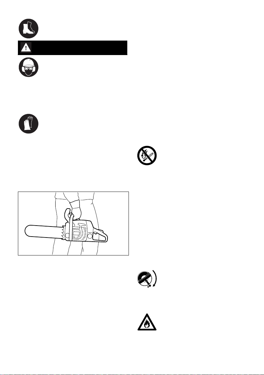
Always carry the chain saw by the handle – with
the hot muffler away from your body, the guide
bar must point to the rear. To avoid serious burn
injuries, avoid touching hot parts of the machine,
especially the surface of the muffler.
In vehicles: Properly secure your saw to prevent
turnover, fuel spillage and damage.
2.5 Cleaning
Clean plastic parts with a cloth. Harsh detergents
can damage the plastic.
Clean the dust and dirt off the machine – do not
use any grease solvents for this purpose.
Clean the ventilation slots if necessary.
Do not use a high-pressure cleaner to clean the
machine. The hard jet of water can damage parts
of the machine.
2.6 Accessories
Only use those tools, guide bars, chains, chain
sprockets, accessories or technically equivalent
components that have been approved by STIHL
for this machine. If you have any questions in
this respect, consult a servicing dealer. Use only
high quality tools and accessories. Otherwise,
there may be a risk of accidents and damage to
the machine.
STIHL recommends the use of genuine STIHL
tools, guide bars, chains, chain sprockets and
accessories. They are specifically designed to
match your model and meet your performance
requirements.
2.7 Refuelling
Gasoline is an extremely flammable
fuel – keep clear of naked flames and
fire – do not spill any fuel – no smok‐
ing.
Switch off the engine before refuelling.
Never refuel the machine while the engine is still
hot – the fuel may spill over – risk of fire!
Open the fuel filler cap carefully so that any
excess pressure is relieved gradually and fuel
does not splash out.
The machine may only be refuelled in a well ven‐
tilated place. Clean the machine immediately if
fuel is spilled. Do not spill fuel over your clothing
– contaminated clothing must be changed imme‐
diately.
The machines can be equipped with the follow‐
ing filler caps as standard:
Cliplock filler cap (bayonet-type)
Place the cliplock filler cap (bayonettype) in position, turn as far as stop
and fold the cliplock down.
This helps reduce the risk of unit vibrations caus‐
ing an incorrectly tightened filler cap to loosen or
come off and spill quantities of fuel.
Look out for leaks! Never start the
engine if fuel has been spilled or is
leaking – Fatal burns may result!
4 0458-153-0121-D

001BA087 LÄ
2 Safety Precautions English
2.8 Before Starting Work
Check that your saw is properly assembled and
in good condition – refer to appropriate chapters
in the instruction manual.
Check the fuel system for leaks, paying spe‐
–
cial attention to visible parts such as the tank
cap, hose connections and the manual fuel
pump (on machines so equipped). If there are
any leaks or damage, do not start the engine –
risk of fire. Have your saw repaired by a serv‐
icing dealer before using it again.
Check operation of chain brake, front hand
–
guard
Correctly mounted guide bar
–
Correctly tensioned chain
–
The trigger and trigger lockout must move
–
freely and spring back to the idle position
when they are released.
Master Control lever must move easily to
–
STOP, 0 or †
Check that the spark plug boot is secure – a
–
loose boot may cause arcing that could ignite
combustible fumes and cause a fire.
Never attempt to modify the controls or safety
–
devices in any way.
Keep the handles dry and clean – free from oil
–
and dirt – for safe control of the saw.
Make sure there is sufficient fuel and chain oil
–
in the tanks.
To reduce the risk of personal injury, do not
operate your saw if it is damaged or not properly
assembled.
2.9 Starting the chain saw
Always work on a level surface. Ensure a firm
and secure footing. Hold the machine securely –
the chain must not touch any objects or the floor
– danger of injury due to the rotating saw chain.
Your chain saw is a one-person saw. Do not
allow other persons to be in the working area –
not even while starting.
Do not start the chain saw if the chain is in a cut.
Move at least 3 meters away from the place
where the machine was refuelled and never start
the motor in enclosed spaces.
Lock the chain with the chain brake before start‐
ing – risk of injury due to rotating chain!
Do not drop-start the engine – start as described
in the Instruction Manual.
2.10 During operation
Ensure you always have a firm and safe footing.
Take special care when the bark is wet – danger
of slipping!
Always hold the chain saw firmly with both
hands: Right hand on the rear handle – even if
you are left-handed. To ensure reliable control,
wrap your thumbs tightly around the handlebar
and handle.
In the event of impending danger or in an emer‐
gency, switch off the engine immediately by mov‐
ing the Master Control lever / stop switch to
STOP, 0 or †.
Never let the machine run unattended.
Exercise caution with slippery surfaces, water,
snow, ice, steep slopes, uneven ground or green
wood that has just been stripped of its bark –
danger of slipping!
Use caution with tree stumps, roots, ditches –
danger of stumbling!
Do not work alone – keep within calling distance
of others who are trained in emergency proce‐
dures and can provide help in an emergency.
Helpers at the cutting site must also wear protec‐
tive clothing (helmet!) and stand well clear of the
branches being cut.
More care and attention than usual are required
when wearing ear protection, as warning sounds
(shouts, beeps, etc.) cannot be heard properly.
Take a break in good time to avoid tiredness or
exhaustion – risk of accidents!
Dust (e. g., sawdust), fumes and smoke pro‐
duced while using the machine may be hazard‐
ous to health. If dust is generated, wear a dust
mask.
When the engine is running: Note that the saw
chain continues to rotate for a short period after
you let go of the throttle trigger – coasting effect.
0458-153-0121-D 5

English 2 Safety Precautions
No smoking when working with or near the chain
saw - risk of fire! Combustible fuel vapour may
escape from the fuel system.
Examine the saw chain periodically at short inter‐
vals and as soon as you note any tangible
changes:
Switch off the engine; wait until the saw chain
–
is stationary
Check condition and secure fitting
–
Check sharpness
–
Never touch the saw chain when the engine is
running. If the saw chain becomes jammed by an
object, switch off the engine immediately before
attempting to remove the object – risk of injury!
Always turn off the engine before leaving the
machine unattended.
To change the saw chain, switch off the engine.
Risk of injury from the motor starting unintention‐
ally!
Keep easily combustible materials (e. g., wood
chips, bark, dry grass, fuel) away from hot
exhaust gases and hot mufflers – risk of fire!
Mufflers with catalytic converters can become
especially hot.
Never work without chain lubrication – monitor
the oil level in the oil tank. Stop work immediately
if the oil level in the oil tank is too low and top up
with chain oil – see also "Topping up with chain
oil" and "Check chain lubrication".
If the machine is subjected to unusually high
loads for which it was not designed (e. g., heavy
impact or a fall), always check that it is in good
condition before continuing work – see also
"Before starting work".
Check the fuel system for leaks and make sure
the safety devices are working properly. Never
continue using a machine that is not in perfect
working order. In case of doubt, have the unit
checked by your servicing dealer.
Check for correct idling, so that the saw chain
stops moving when the throttle trigger is
released. Check the idle setting regularly and
correct when possible. Have the machine
repaired by a STIHL servicing dealer if the saw
chain still continues to move during idling.
The chain saw produces poisonous
exhaust gases as soon as the engine
starts. These gases may be colour‐
less and odourless and may contain
unburnt hydrocarbons and benzene.
Never work with the machine indoors
or in poorly ventilated areas, even if
Ensure proper ventilation when working in
trenches, hollows or other confined locations –
risk of fatal injury from breathing toxic fumes!
If you feel sick, have a headache, vision prob‐
lems (e. g., your field of vision gets smaller),
hearing problems, dizziness or inability to con‐
centrate, stop work immediately. Such symptoms
may be caused by an excessively high concen‐
tration of exhaust emissions – risk of accident!
2.11 After finishing work
Switch off the motor, engage the chain brake and
attach the chain scabbard.
2.12 Storage
When the machine is not in use, it should be
stored in such a way that no-one is endangered.
Secure the machine against unauthorised use.
Store the machine in a safe, dry room.
2.13 Vibrations
Prolonged use of the power tool may result in
vibration-induced circulation problems in the
hands (whitefinger disease).
No general recommendation can be given for the
length of usage because it depends on several
factors.
The period of usage is prolonged by:
–
–
The period of usage is shortened by:
–
–
–
Continual and regular users should monitor
closely the condition of their hands and fingers. If
any of the above symptoms appear (e.g. tingling
sensation in fingers), seek medical advice.
2.14 Maintenance and repairs
Always switch off the engine before any repair,
cleaning or maintenance work and any work on
the chain. Risk of injury if the engine starts inad‐
vertently!
The machine must be serviced regularly. Do not
attempt any maintenance or repair work not
your machine is equipped with a cata‐
lytic converter.
Hand protection (wearing warm gloves)
Work breaks
Any personal tendency to suffer from poor cir‐
culation (symptoms: frequently cold fingers,
tingling sensations).
Low outside temperatures.
The force with which the handles are held (a
tight grip restricts circulation).
6 0458-153-0121-D
001BA036 KN
001BA257 KN
3 Reactive Forces English
described in the Instruction Manual. All other
work should be carried out by a servicing dealer.
STIHL recommends that maintenance and repair
work be carried out only by authorised STIHL
dealers. STIHL dealers receive regular training
and are supplied with technical information.
Use only high-quality spare parts. Otherwise,
there may be a risk of accidents and damage to
the machine. If you have any questions in this
respect, consult a servicing dealer.
Do not modify the machine in any way – this may
increase the risk of personal injury –risk of acci‐
dents!
To reduce the risk of fire due to ignition outside
the cylinder, move the master control level to
STOP, 0 or † before turning the engine over on
the starter when the spark plug boot is removed
or the spark plug is unscrewed!
Do not service or store the machine near a
naked flame – risk of fire due to the fuel!
Check fuel cap regularly for tightness.
Use only spark plugs that are in perfect condition
and have been approved by STIHL – see "Speci‐
fications".
Check ignition lead (insulation in good condition,
secure connection).
Check that the muffler is in perfect working con‐
dition.
Do not use the machine if the muffler is damaged
or missing – risk of fire, damage to hearing!
Never touch a hot muffler – risk of burns!
The condition of the anti-vibration elements influ‐
ences vibration behaviour – inspect anti-vibration
elements periodically.
Inspect chain catcher – replace if damaged.
Switch off the engine
To check the chain tension
–
To retension the chain
–
To replace the chain
–
For remedying malfunctions
–
Observe sharpening instructions – for safe and
proper handling, always keep the chain and
guide bar in flawless condition. Keep the chain
properly sharpened, tensioned and well lubrica‐
ted.
Change chain, guide bar and chain sprocket in
due time.
Regularly check that the clutch drum is in perfect
working condition.
Always store fuel and chain lubricant only in the
specified type of containers and ensure they are
correctly labelled. Store in a dry, cool and secure
place protected against light and sunlight.
In the event of a chain brake malfunction, switch
off the machine immediately – risk of injury! Con‐
sult a servicing dealer – do not use the machine
until the malfunction has been remedied, see
"Chain brake".
3 Reactive Forces
The most common reactive forces that occur dur‐
ing cutting are: kickback, pushback and pull-in.
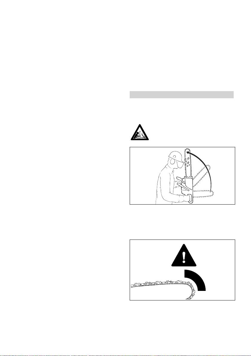
3.1 Dangers of kickback
Kickback can result in serious or fatal
injury.
(Kickback) occurs when the saw is suddenly
thrown up and back in an uncontrolled arc
towards the operator.
3.2 Kickback occurs if, e. g.,
when the upper quadrant of the bar nose unin‐
–
tentionally contacts wood or another solid
object, e.g. when another limb is touched acci‐
dentally during limbing.
when the chain at the nose of the guide bar is
–
pinched in the cut.
0458-153-0121-D 7

001BA037 KN
A
001BA038 KN
B
English 4 Working Techniques
3.3 Quickstop chain brake:
This device reduces the risk of injury in certain
situations – it cannot prevent kickback. When
activated, the chain brake stops the saw chain
within a fraction of a second –
see the section "Saw chain" in this Instruction
Manual.
3.6 Pushback (B)
3.4 To reduce the risk of kickback
Work cautiously and avoid situations which
–
could cause kickback.
Hold the saw firmly with both hands and main‐
–
tain a secure grip.
always cut at full throttle.
–
Be aware of the location of the guide bar nose
–
at all times.
do not cut with the bar nose.
–
Take special care with small, tough limbs, they
–
may catch the chain.
never cut several limbs at once.
–
do not overreach.
–
never cut above shoulder height.
–
Use extreme caution when re-entering a previ‐
–
ous cut.
Do not attempt plunge cuts if you are not
–
experience in this cutting technique.
be alert for shifting of the log or other forces
–
that may cause the cut to close and pinch the
chain.
always cut with a correctly sharpened, prop‐
–
erly tensioned chain – the depth gauge setting
must not be too large.
Use a low kickback chain and a narrow radius
–
guide bar.
3.5 Pull-in (A)
Pushback occurs when the chain on the top of
the bar is suddenly pinched, caught or encoun‐
ters a foreign object in the wood. The reaction of
the chain drives the saw straight back toward the
operator – to avoid this risk:
Be alert to situations that may cause the top of
–
the guide bar to be pinched
Do not twist the guide bar in the cut
–
3.7 Exercise extreme caution
with leaners
–
with trees that have fallen unfavorably
–
between other trees and are under strain
when working in blowdown areas.
–
In these cases, do not use a chain saw – use a
hoist, winch or drag line instead.
Pull out exposed and cleared logs. Select clear
area for cutting.
Deadwood (dry, decayed or rotted wood) repre‐
sents a considerable risk that is difficult to
assess. Identifying the extent of the dangers is
complicated, if not impossible. Use aids such as
a cable winch or tractor in such cases.
When felling in the vicinity of roads, railways,
power lines, etc., take extra precautions. If nec‐
essary, inform the police, utility company or rail‐
way authority.
4 Working Techniques
Sawing and felling work, including all related
work (plunge cutting, limbing, etc.) may only be
carried out by persons who have been specially
trained and instructed. Persons who are not
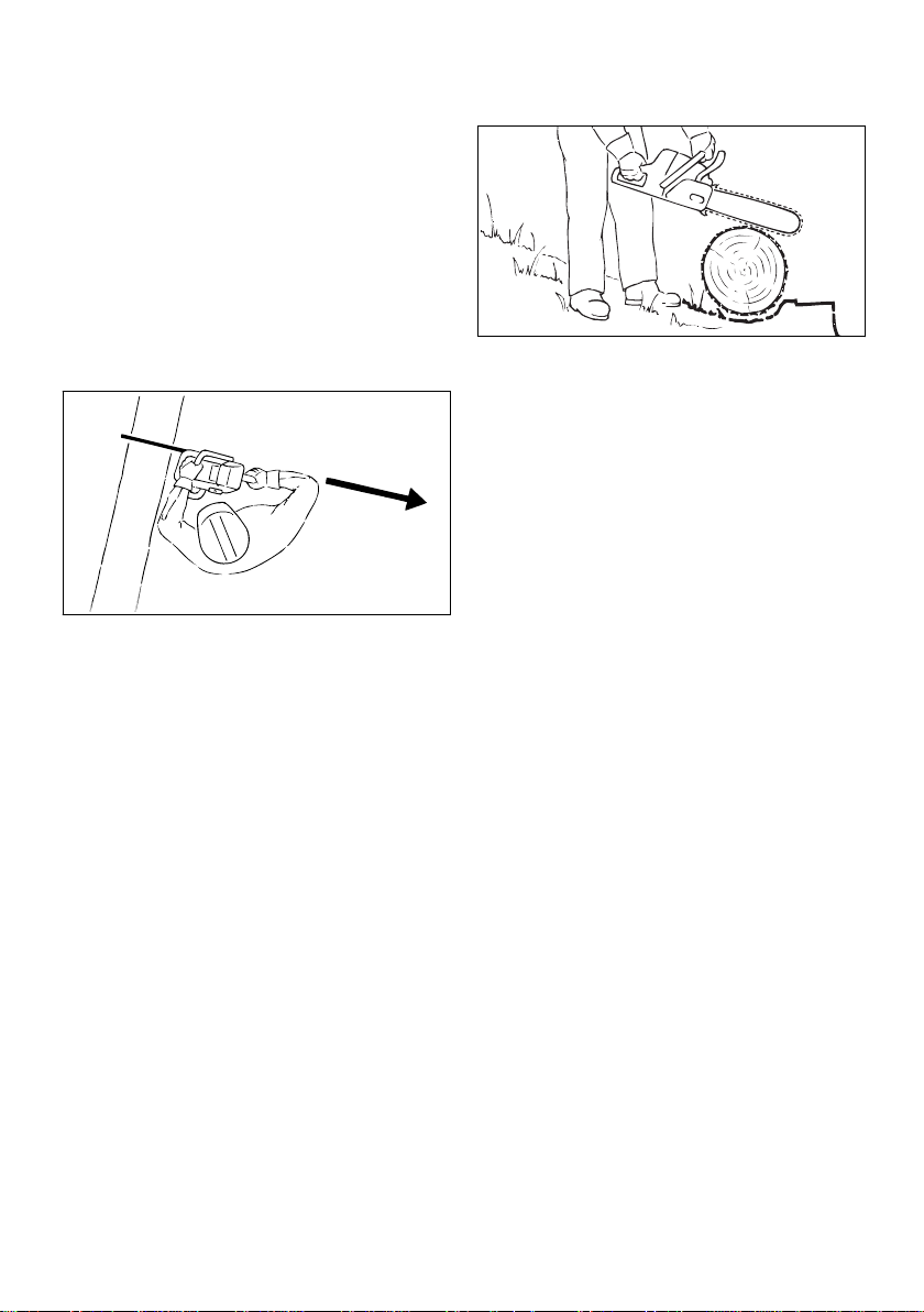
Pull-in occurs when the chain on the bottom of
the bar is suddenly pinched, caught or encoun‐
ters a foreign object in the wood. The reaction of
the chain pulls the saw forward – to reduce this
risk, always engage the spiked bumper securely
in the tree or limb.
8 0458-153-0121-D
experienced chain saw users should not carry
out any such work – increased risk of accidents!
Country-specific legislation on felling technique
must be complied with during felling work.
001BA082 KN
001BA033 KN
4 Working Techniques
4.1 Sawing
Do not operate your saw with the starting throttle
lock engaged. Engine speed cannot be control‐
led with the throttle trigger in this position.
Work calmly and carefully – in daylight conditions
and only when visibility is good. Ensure you do
not endanger others – stay alert at all times.
It is advisable for first-time users to practice cut‐
ting logs on a sawbuck – see "Sawing thin
wood".
Use the shortest possible guide bar: The chain,
guide bar and chain sprocket must match each
other and your saw.
Position the saw so that your body is clear of the
cutting attachment.
Always pull the saw out of the cut with the chain
running.
Use your chain saw for cutting only. It is not
designed for prying or shoveling away limbs,
roots or other objects.
Do not underbuck freely hanging limbs.
Be careful when cutting scrub and young trees.
Thin shoots can be scooped up by the chain saw
and hurled towards the user.
Be careful when cutting splintered wood – Risk of
injury from ejected pieces of wood!
Make sure your saw does not touch any foreign
materials: Stones, nails, etc. may be flung off
and damage the saw chain. The chain saw may
kick back unexpectedly – risk of accident!
If a rotating saw chain hits a stone or another
hard object, sparks may be generated which may
ignite easily flammable materials under certain
conditions. Also dried-out plants and brushwood
are combustible, above all in hot and dry
weather. If there is a risk of fire, do not use the
chain saw in the vicinity of easily combustible
materials, dry plants or scrub. It is mandatory
English
that you ask the responsible forestry office about
the current fire hazard.
If on a slope, stand on the uphill side of the log.
Watch out for rolling logs.
When working at heights:
Always use a lift bucket
–
Never use the machine while standing on a
–
ladder or in a tree
Never work on an insecure support
–
Never work above shoulder height
–
Never use the machine with just one hand
–
Begin cutting with the saw at full throttle and
engage the spiked bumper firmly in the wood,
and then continue cutting.
Never work without the spiked bumper because
the saw may pull you forwards and off balance.
Always hold the spiked bumper securely against
the tree or limb.
At the end of the cut, the chain saw is no longer
supported by the cutting attachment in the cut.
The chain saw's weight must be borne by the
user – risk of loss of control!
Sawing thin wood:
Use a sturdy and stable support – sawhorse.
–
Never hold the log with your leg or foot.
–
never allow another person to hold the log or
–
help in any other way.
Limbing
use a low kickback chain.
–
Work with the saw supported wherever possi‐
–
ble.
do not stand on the log while limbing it.
–
do not cut with the bar nose.
–
watch for limbs which are under tension.
–
never cut several limbs at once.
–
Lying or standing logs under tension:
Always make the cuts in the correct order (first
compression side (1), then tension side (2)), oth‐
erwise the cutting attachment may stick in the cut
or kick back – risk of injury!
0458-153-0121-D 9

1
001BA151 KN
2
1
001BA152 KN
2
001BA189 KN
001BA088 LÄ
2
/
1
2
1 1
/
1
2
001BA040 KN
B
B
English 4 Working Techniques
Make sure no-one is endangered by the falling
tree – the noise of your engine may drown any
warning calls.
Maintain a distance of at least 2 1/2 tree lengths
from the next felling site.
Determining direction of fall and escape path
Select gap in stand into which you want the tree
to fall.
► Make relieving cut at the compression side (1)
► Make bucking cut at the tension side (2)
Be wary of pushback when making bucking cut
from the bottom upwards (underbuck).
NOTICE
Do not cut a lying log at a point where it is touch‐
ing the ground because the saw chain will other‐
wise be damaged.
Ripping:
Pay special attention to the following points:
The natural inclination of the tree
–
Unusually heavy limb structure, asymmetrical
–
growth, damage to tree
The wind direction and speed – do not fell in
–
high winds
Direction of slope
–
Neighboring trees
–
Snow load
–
Take the general condition of the tree into
–
account – be especially careful with trunk
damage or deadwood (brittle, rotten or dead
wood)
Sawing technique without use of the spiked
bumper – risk of pull-in – position the guide bar at
as shallow an angle as possible – be especially
careful – increased risk of kickback!
4.2 Preparing for felling
Check that there are no other persons in the fell‐
ing area – other than helpers.
10 0458-153-0121-D
A Direction of fall
B Escape path (escape routes)
Establish escape paths for each worker –
–
approx. 45° diagonally opposite to the direc‐
tion of fall
Clear escape paths, eliminate obstacles
–
Put down tools and equipment at a safe dis‐
–
tance – but not on the escape paths

001BA146 KN
001BA271 KN
C
C
001BA153 KN
001BA153 KN
4 Working Techniques English
When felling, stand only to the side of the fall‐
–
ing trunk and only move back laterally onto the
escape path
Plan escape paths on slopes parallel to the
–
Determine direction of fall with gunning sight on
cover and fan housing
slope
When walking away along the escape path,
–
watch out for falling limbs and watch the top of
the tree.
Preparing work area at base of tree
First clear the tree base and work area from
–
interfering limbs and brush to provide a secure
footing.
Carefully clear the base of the trunk (e.g., with
–
an axe) – sand, stones and other foreign
objects will blunt the saw chain
Your chainsaw has a gunning sight on the cover
and fan housing. Use this gunning sight.
Making the felling notch
When making a felling notch, align the chainsaw
so that the notch lies at a right angle to the direc‐
tion of fall.
During the procedure, various sequences are
permitted for making a felling notch with a bottom
(horizontal) cut and top (angled) cut – comply
with national legislation regarding felling techni‐
que.
Remove largest buttresses: first the largest
–
buttress – saw first vertically, then horizontally
– only if the tree is in sound condition
4.3 Felling notch
► Make a bottom (horizontal) cut
► Make the top (angled) cut approx. 45°‑ 60° to
the bottom cut
Checking the direction of fall
Preparing the felling notch
► Insert the chainsaw with guide bar in the bot‐
The felling notch (C) determines the direction of
fall.
Important:
Make a felling notch at right angle to direction
–
tom of the felling notch. The gunning sight
must point in the planned direction of fall – if
necessary, correct direction of fall by re-cutting
the felling notch.
of fall
Saw as close to the ground as possible
–
Cut to a depth of approx. 1/5 to 1/3 of the
–
diameter of the trunk
0458-153-0121-D 11

001BA150 KN
001BA259 KN
G
E
C
C
Ø
1/10
001BA269 KN
3.
1.
2.
001BA270 KN
English
4.4 Sapwood cuts
Sapwood cuts in long-fibered softwood help pre‐
vent sapwood splintering when the tree falls.
Make cuts at both sides of the trunk at same
height as bottom of felling notch to a depth of
about 1/10 of trunk diameter. On large diameter
trees, cut to no more than width of guide bar.
Do not make sapwood cuts if wood is diseased.
4.5 Basic information on felling cut
Basic dimensions
4 Working Techniques
With rotten trunks, leave a wider strip
–
Plunge cutting
For relieving cuts during shortening
–
For wood carving
–
► Use a low kickback saw chain and proceed
with special care
1. Begin cut by applying the lower portion of the
guide bar nose – do not use upper portion
because of risk of kickback. Cut at full
strength until the depth of the kerf is twice
the width of the guide bar
2. Swing the machine slowly into the plunge
cutting position – risk of kickback and push‐
back!
3. Make the plunge cut very carefully. Risk of
pushback.
The felling notch (C) determines the direction of
fall.
The hinge (D) functions like a real hinge to guide
the tree to the ground.
Width of hinge: approx. 1/10 of the trunk diam‐
–
eter
Never saw through the hinge while felling –
–
otherwise the tree will fall in a direction other
than the one planned – risk of accident!
With rotten trunks, leave a wider hinge
–
The tree is felled with the felling cut (E).
Cut horizontally
–
1/10 (at least 3 cm) of tree diameter higher
–
than bottom of felling notch (C).
The holding strap (F) or stabilizing strap (G) sup‐
ports the tree and helps prevent it from falling
prematurely.
Width of strip: approx. 1/10 to 1/5 of the trunk
–
diameter
Do not cut into the strip during the felling cut
–
12 0458-153-0121-D
Where possible, use a plunge blade. The plunge
blade and the upper/lower side of the guide bar
are parallel.
During plunge cutting, the plunge bar helps to
keep the hinge parallel in form, i.e. the same
thickness at all points. To do this, guide the
plunge bar parallel to the sink chord.
Felling wedges
Insert the felling wedge as soon as possible, i.e.
as soon as no obstruction of saw control is to be
expected. Position the felling wedge in the felling
cut and drive in with suitable tools.
Only use aluminum or plastic wedges – do not
use steel wedges. Steel wedges can seriously

001BA260 KN
001BA261 KN
1.
2.
001BA273 KN
3.
001BA263 KN
4.
5.
1.
2.
3.
4 Working Techniques English
damage the saw chain and cause dangerous
kickback.
Select suitable felling wedges dependent on the
trunk diameter and the width of the kerf (ana‐
logue to felling cut (E)).
Contact the STIHL dealer for the selection of the
felling wedge (suitable length, width and height).
4.6 Selecting the appropriate felling cut
The selection of the appropriate felling cut is
dependent on the same tree characteristics that
must be noted when determining the direction of
fall and the escape paths.
There are various different features of these
characteristics. This User Manual will only
describe the two most commonly occurring var‐
iants:
left: Normal tree – vertically upright tree
with uniform crown
right: Leaner tree - crown pointing in direc‐
tion of fall
Shout a warning before starting the felling cut.
► Plunge cut the felling cut (E) – plunge the
guide bar fully in
► Engage the spiked bumper behind the hinge
and use this as the rotation point – reposition
the chainsaw as little as possible
► Make the felling cut up to the hinge (1)
Do not cut into the hinge
–
► Make the felling cut up to the stabilizing
strap (2)
Do not cut into the stabilizing strap
–
► Set the felling wedge (3)
Shout a second warning immediately before the
tree falls.
► Cut through the stabilizing strap, horizontal
level with the felling cut, with arms fully exten‐
ded
B) Thick trunks
Implement this felling cut when the trunk diame‐
ter is greater than the cutting length of the
machine.
4.7 Felling cut with stabilizing strap (normal tree)
A) Thin trunks
Implement this felling cut when the trunk diame‐
ter is smaller than the cutting length of the chain‐
saw.
Shout a warning before starting the felling cut.
► Engage the spiked bumper at the height of the
felling cut and use this as the rotation point –
0458-153-0121-D 13
reposition the chainsaw as little as possible
► Tip of the guide bar must penetrate the wood
before the hinge (1) – guide the chainsaw
absolutely horizontally and swivel as widely as
possible
► Make the felling cut up to the hinge (2)
Do not cut into the hinge
–

001BA274 KN
6.
001BA265 KN
1.
2.
001BA266 KN
001BA267 KN
1.
2.
3.
4.
5.
6.
English 4 Working Techniques
► Make the felling cut up to the stabilizing
strap (3)
Do not cut into the stabilizing strap
–
The felling cut must be continued on the oppo‐
► Make the felling cut towards the holding strap
(2)
Cut horizontally
–
Do not cut into the holding strap.
–
site side of the trunk.
Ensure that the second cut is at the same level
as the first cut.
► Plunge cut the felling cut
► Make the felling cut up to the hinge (4)
Do not cut into the hinge
–
► Make the felling cut up to the stabilizing
strap (5)
Do not cut into the stabilizing strap
–
Shout a second warning immediately before the
tree falls.
► With outstretched arms, cut through the hold‐
ing strap at a downward angle from outside.
B) Thick trunks
► Set the felling wedge (6)
Shout a second warning immediately before the
tree falls.
► Cut through the stabilizing strap, horizontal
level with the felling cut, with arms fully exten‐
ded
4.8 Felling Cut with Holding Strap (Leaner)
A) Thin trunks
Implement this felling cut when the trunk diame‐
ter is smaller than the cutting length of the chain‐
saw.
Perform this felling cut when the tree diameter is
greater than the cutting length of the chainsaw.
► Engage the spiked bumper behind the holding
strap and use it as a pivot – avoid reposition‐
ing the chainsaw more than necessary.
► The guide bar nose enters the wood (1) before
it reaches the hinge – hold the chainsaw hori‐
zontally and swing it as far as possible.
Do not cut into the holding strap or hinge.
–
► Make the felling cut up to the hinge (2)
Do not cut into the hinge
–
► Make the felling cut up to the holding strap (3)
Do not cut into the holding strap.
–
The felling cut must be continued on the oppo‐
site side of the trunk.
Ensure that the second cut is at the same level
► Plunge cut the guide bar into the trunk until it
exits on the other side
► Make the felling cut (E) towards the hinge (1)
Cut horizontally
–
Do not cut into the hinge
–
as the first cut.
► Engage the spiked bumper behind the hinge
and use this as the rotation point – reposition
the chainsaw as little as possible
14 0458-153-0121-D
001BA268 KN
001BA248 KN
1
2
3
a
001BA244 KN
001BA245 KN
1
1
5 Cutting Attachment English
► Tip of the guide bar must penetrate the wood
before the holding strap (4) – guide the chain‐
saw absolutely horizontally and swivel as
widely as possible
► Make the felling cut up to the hinge (5)
Do not cut into the hinge
–
► Make the felling cut up to the holding strap (6)
Do not cut into the holding strap.
–
Shout a second warning immediately before the
tree falls.
► With outstretched arms, cut through the hold‐
ing strap at a downward angle from outside.
5 Cutting Attachment
A cutting attachment consists of the saw chain,
guide bar and chain sprocket.
The cutting attachment that comes standard is
designed to exactly match the chain saw.
5.1 Chain Scabbard
Your saw comes standard with a chain scabbard
that matches the cutting attachment.
If guide bars of different lengths are mounted to
the saw, always use a chain scabbard of the cor‐
rect length which covers the complete guide bar.
The length of the matching guide bars is marked
on the side of the chain scabbard.
Guide bars longer than 90 cm require one scab‐
bard extension. Guide bars longer than 120 cm
require two scabbard extensions.
Depending on the model, the scabbard exten‐
sion either comes standard with the saw or is
available as a special accessory.
5.2 Fitting Chain Scabbard Exten‐
sion
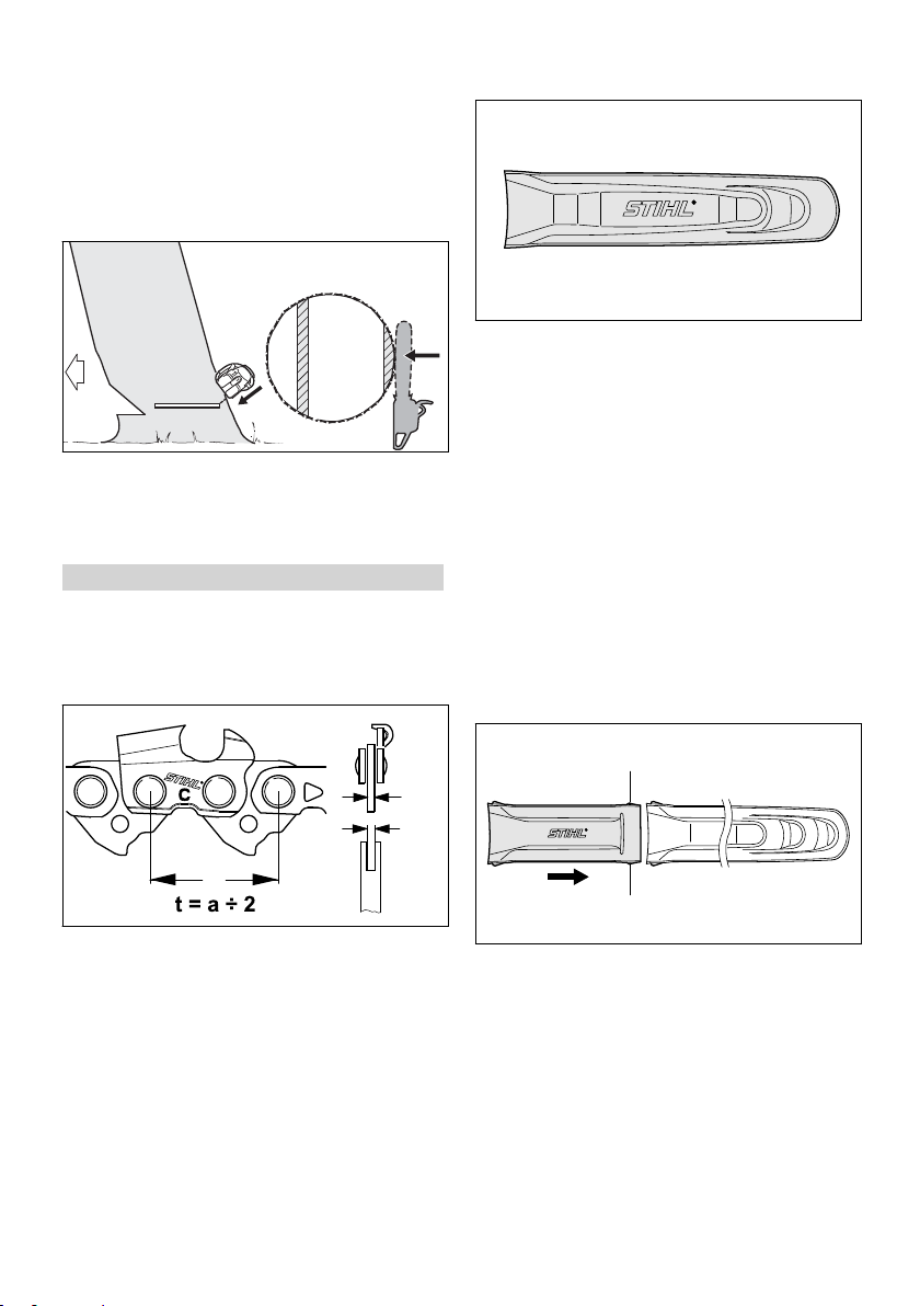
The pitch (t) of the saw chain (1), chain
–
sprocket and the nose sprocket of the Rollo‐
matic guide bar must match.
The drive link gauge (2) of the saw chain (1)
–
must match the groove width of the guide
bar (3).
If non-matching components are used, the cut‐
ting attachment may be damaged beyond repair
after a short period of operation.
► Push the scabbard extension and chain scab‐
bard together – the lugs (1) must engage in
the chain scabbard.
0458-153-0121-D 15
5902BA020 KN
1
2
001BA185 KN
001BA186 KN
143BA003 KN
3
1
1
2
4
001BA187 KN
English 6 Mounting the Bar and Chain (side chain tensioner)
6 Mounting the Bar and
6.3 Fitting the chain
Chain (side chain ten‐
sioner)
6.1 Removing the chain sprocket cover
WARNING
Wear work gloves to protect your hands from the
sharp cutters.
► Fit the chain – start at the bar nose.
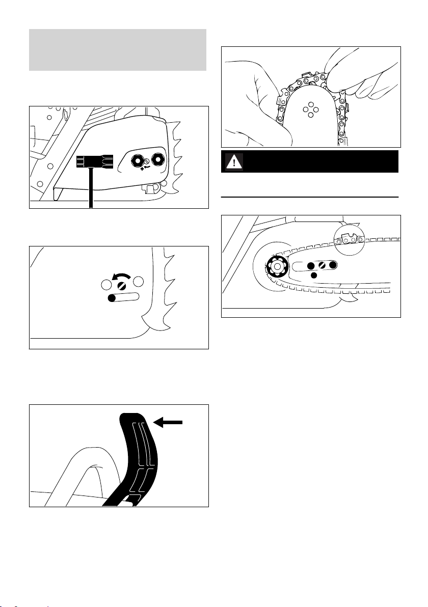
► Rotate the captive nuts counterclockwise until
they hang loosely in the sprocket cover.
► Remove the sprocket cover with captive nuts.
► Fit the guide bar over the studs (1) – the cut‐
ting edges on the top of the bar must point to
the right.
► Turn the screw (1) counterclockwise until the
tensioner slide (2) butts against the left end of
the housing slot.
6.2 Disengaging the chain brake
► Pull the hand guard towards the front handle
until there is an audible click – the chain brake
is disengaged.
16 0458-153-0121-D
► Engage the peg of the tensioner slide in the
locating hole (2) –- place the chain over the
sprocket (3) at the same time.
► Turn the tensioning screw (4)clockwise until
there is very little chain sag on the underside
of the bar – and the drive link tangs are
engaged in the bar groove.
► Refit the sprocket cover and tighten the nuts
only moderately by hand (they are finally tight‐
ened after the saw chain is tensioned).
► Go to chapter on "Tensioning the Saw Chain"

133BA026 KN
2
1
3
1
172BA007 KN
2
172BA008 KN
1
5
4
3
172BA009 KN
2
172BA010 KN
001BA186 KN
7 Mounting the Bar and Chain (quick chain tensioner) English
7 Mounting the Bar and
Chain (quick chain ten‐
sioner)
7.1 Removing the chain sprocket cover
► Position the tensioning gear (1) against the
guide bar (3) so that the stud (4) projects
through the upper hole and the short guide
peg (5) locates in the lower hole.
► Pull the hinged handle (1) out (until it
engages)
► Turn the wingnut (2) counterclockwise until it
hangs loose
► In the sprocket cover (3).
► Remove the chain sprocket cover
7.2 Fitting the tensioning gear
► Screw the nut (2) on to the stud as far as stop
by hand.
7.3 Disengage the chain brake.
► Remove the tensioning gear (1) and turn it
over.
► Pull the hand guard towards the front handle
until there is an audible click – the chain brake
is disengaged.
► Unscrew the nut (2).
0458-153-0121-D 17
1
172BA011 KN
3
2
172BA012 KN
172BA013 KN
3
172BA014 KN
5
4
172BA015 KN
English 7 Mounting the Bar and Chain (quick chain tensioner)
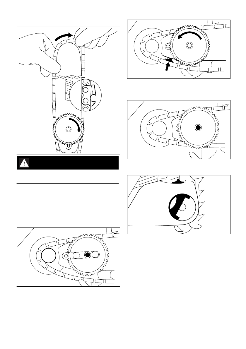
7.4 Fitting the saw chain
► Guide the drive link into the bar groove (see
arrow) and turn the tensioning gear to the left
as far as possible
WARNING
Wear work gloves to protect your hands from the
sharp cutters.
► Fit the chain – start at the bar nose. Pay atten‐
tion to the position of the tensioning gear and
the cutting edges.
► Turn the tensioning gear (1) clockwise as far
as stop.
► Turn the guide bar so that the tensioning gear
is facing you.
► Fit the chain over the sprocket (2).
► Fit guide bar in position – the collar screw (3)
engages the hole in the tensioning gear. The
heads of the two short collar screws locate in
the guide bar slot.
► Fit the chain sprocket cover so that the wing‐
nut locates on the collar screw (3).
When fitting the chain sprocket cover, the teeth
of the adjusting wheel and the tensioning gear
must mesh; if necessary,
► Turn the adjusting wheel (4) a little until the
chain sprocket cover can be slid completely
against the engine housing
► Pull the hinged handle (5) out (until it engages
in the upright position)
► Fit wing nut and tighten lightly
► Go to chapter on "Tensioning the Saw Chain"
18 0458-153-0121-D

1
133BA024 KN
1
2
001BA112 KN
143BA007 KN
8 Tensioning the Saw Chain (side chain tensioner) English
8 Tensioning the Saw Chain
► Check chain tension frequently – see chapter
on "Operating Instructions".
(side chain tensioner)
10 Checking Chain Tension
Retensioning during cutting work:
► Shut off the engine.
► Loosen the nuts.
► Hold the bar nose up.
► Use a screwdriver to turn the tensioning
screw (1) clockwise until the chain fits snugly
against the underside of the bar.
► While still holding the bar nose up, tighten
down the nuts firmly.
► Go to "Checking Chain Tension".
A new chain has to be retensioned more often
than one that has been in use for some time.
► Check chain tension frequently – see chapter
on "Operating Instructions".
9 Tensioning the Saw Chain
(quick chain tensioner)
Retensioning during cutting work:
► Shut off the engine.
► Pull out the hinged clip and loosen the wing‐
nut.
► Turn the adjusting wheel (1) clockwise as far
as stop.
► Tighten down the wingnut (2) firmly by hand.
► Fold down the hinged clip.
► Go to "Checking Chain Tension"
A new chain has to be retensioned more often
than one that has been in use for some time.
► Shut off the engine.
► Wear work gloves to protect your hands.
► The chain must fit snugly against the under‐
side of the bar and it must still be possible to
pull the chain along the bar by hand.
► If necessary, retension the chain.
A new chain has to be retensioned more often
than one that has been in use for some time.
► Check chain tension frequently – see chapter
on "Operating Instructions".
11 Fuel
The engine requires a mixture of gasoline and
engine oil.
WARNING
Avoid direct skin contact with fuel and breathing
in of gasoline fumes.
11.1 STIHL MotoMix
STIHL recommends using STIHL MotoMix. This
pre-blended fuel is free of benzene and lead, is
distinguished by a high octane rating, and
always provides the proper mixing ratio.
STIHL MotoMix uses STIHL HP Ultra two-stroke
engine oil for optimum engine life.
MotoMix is not available in all markets.
0458-153-0121-D 19
001BA229 KN
English 12 Fueling
11.2 Mixing fuel
NOTICE
Unsuitable fuels or a mixing ratio that deviates
from the specification can lead to severe engine
damage. The engine, seals, fuel lines and fuel
tank may be damaged if low-quality gasoline or
engine oil is used.
11.2.1 Gasoline
Use only high-quality gasoline with an octane rat‐
ing of at least 90 ROC – leaded or unleaded.
Gasoline with an alcohol component exceeding
10% can cause impaired engine performance in
engines with manually adjustable carburetors
and thus should not be used in these engines.
Engines with M-Tronic deliver full engine per‐
formance using gasoline with an alcohol compo‐
nent of up to 27% (E27).
11.2.2 Engine oil
If you mix the fuel yourself, use only STIHL twostroke engine oil or another high-performance
engine oil classified as JASO FB, JASO FC,
JASO FD, ISO-L-EGB, ISO-L-EGC or ISO-LEGD.
STIHL specifies STIHL HP Ultra two-stroke
engine oil or an equivalent high-performance
engine oil in order to maintain emission limits
over the machine’s service life.
11.2.3 Mixing ratio
with STIHL two-stroke engine oil 1:50; 1:50 =
1 part oil + 50 parts gasoline
11.2.4 Examples
Quantity of gaso‐
line
Liters Liters (ml)
1 0.02 (20)
5 0.10 (100)
10 0.20 (200)
15 0.30 (300)
20 0.40 (400)
25 0.50 (500)
► Pour oil into an approved safety fuel canister
first, then add gasoline and mix thoroughly
STIHL two-stroke
engine oil 1:50
Fuel mixture deteriorates with age – mix only as
much as needed for a few weeks. Do not store
fuel mixture for longer than 30 days. The fuel
mixture can become unusable more quickly if
exposed to light, sunlight or low or high tempera‐
tures.
STIHL MotoMix however can be stored for up to
5 years without any problems.
► Shake the canister containing the fuel mixture
thoroughly before refueling
WARNING
Pressure may have built up in the canister –
open it carefully.
► The fuel tank and the canister in which fuel
mixture is stored should be cleaned thoroughly
from time to time
Residual fuel and the liquid used for cleaning
must be disposed of in accordance with regula‐
tions and without harming the environment!
12 Fueling
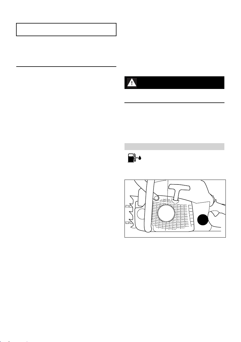
12.1 Preparing the machine
► Before fueling, clean the cap and the area
around it to ensure that no dirt falls into the
fuel tank
► Always position the machine so that the cap is
facing upwards
11.3 Storing fuel mixture
Store in approved safety fuel canisters only in a
dry, cool and secure place protected against light
and sunlight.
20 0458-153-0121-D
001BA236 KN
001BA232 KN
001BA234 KN
001BA237 KN
001BA234 KN
001BA233 KN
001BA231 KN
12 Fueling English
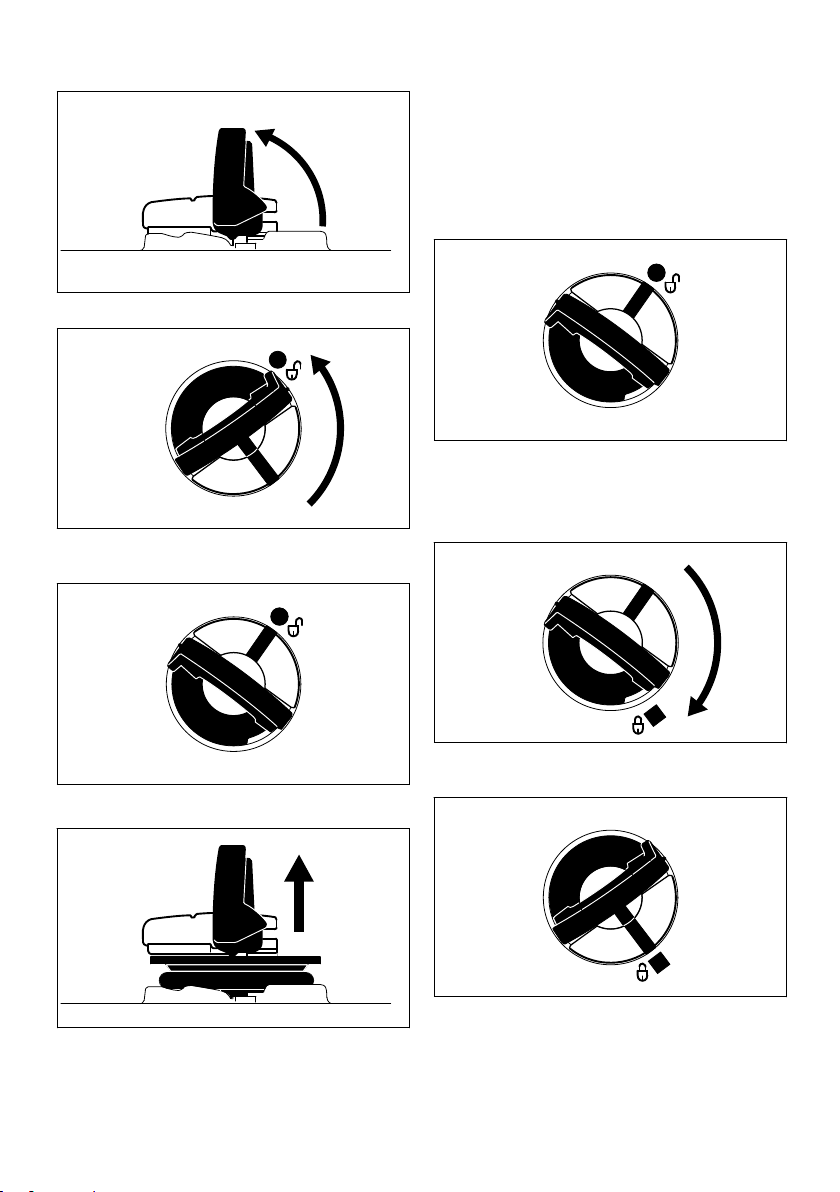
12.2 Opening
12.3 Filling Up with Fuel
Take care not to spill fuel while fueling and do
not overfill the tank.
STIHL recommends you use the STIHL filler noz‐
zle for fuel (special accessory).
► Fill the fuel tank.
12.4 Closing
► Raise grip to vertical position.
Grip must be vertical:
► Fit the cap – marks on tank cap and fuel tank
must line up.
► Press the cap down as far as stop.
► Turn the cap counterclockwise (about a quar‐
ter turn).
► While holding the cap depressed, turn it clock‐
wise until it engages in position.
Marks on tank cap and fuel tank must line up.
The marks on the tank cap and fuel tank are then
► Remove the tank cap.
in alignment.
0458-153-0121-D 21
001BA235 KN
001BA241 KN
1
001BA238 KN
001BA239 KN
English 13 Chain Lubricant
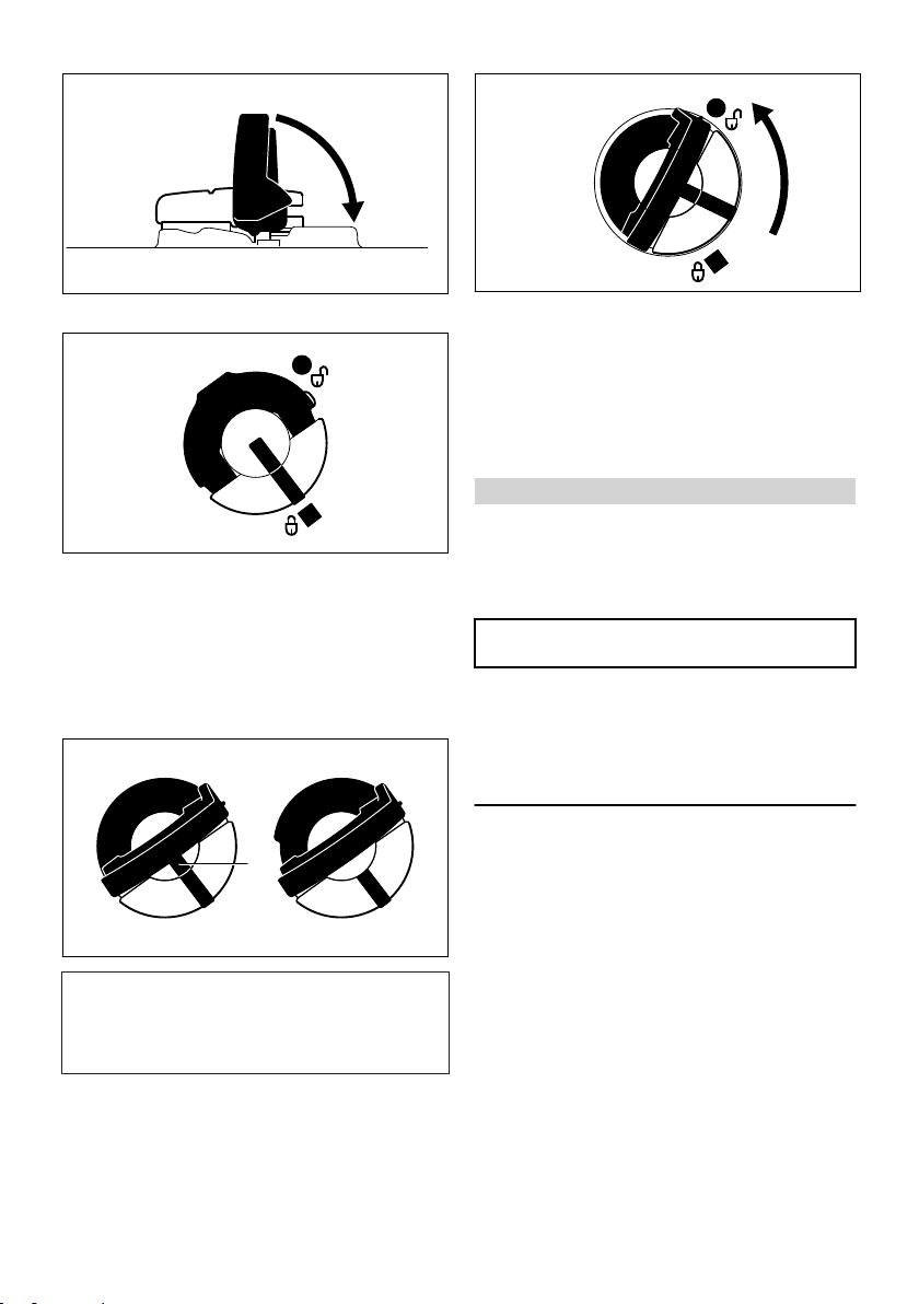
► Fold the grip down.
Tank cap is locked.
12.5 If the tank cap cannot be
locked in the fuel tank opening
Bottom of cap is twisted in relation to top.
► Remove the cap from the fuel tank and check
it from above.
► Place the cap on the opening and rotate it
counterclockwise until it engages the filler
neck.
► Continue rotating the cap counterclockwise
(about a quarter turn) – this causes the bottom
of the cap to be turned to the correct position.
► Turn the cap clockwise and lock it in position –
see section on "Closing".
13 Chain Lubricant
For automatic and reliable lubrication of the
chain and guide bar – use only an environmen‐
tally compatible quality chain and bar lubricant.
Rapidly biodegradable STIHL BioPlus is recom‐
mended.
NOTICE
Biological chain oil must be resistant to aging
(e.g. STIHL BioPlus), since it will otherwise
quickly turn to resin. This results in hard deposits
that are difficult to remove, especially in the area
of the chain drive and chain. It may even cause
the oil pump to seize.
The service life of the chain and guide bar
depends on the quality of the lubricant. It is
therefore essential to use only a specially formu‐
lated chain lubricant.
Left: Bottom of cap is twisted – inner
Right: Bottom of cap in correct position –
mark (1) in line with outer mark.
inner mark is under the grip. It is not
in line with the outer mark.
22 0458-153-0121-D
001BA158 KN
143BA024 KN
143BA011 KN
14 Filling Chain Oil Tank English
WARNING
Do not use waste oil. Renewed contact with
waste oil can cause skin cancer. Moreover,
waste oil is environmentally harmful.
NOTICE
Waste oil does not have the necessary lubricat‐
ing properties and is unsuitable for chain lubrica‐
tion.
14 Filling Chain Oil Tank
14.1 Preparations
► Thoroughly clean the oil filler cap and the area
around it to ensure that no dirt falls into the
tank.
► Position the machine so that the filler cap is
facing up.
► Open the filler cap.
14.2 Fill up with chain oil.
► Refill the chain oil tank every time you refuel.
Take care not to spill chain oil while refilling and
do not overfill the tank.
STIHL recommends you use the STIHL filler noz‐
zle for chain oil (special accessory).
► Close the filler cap.
There must still be a small amount of oil in the oil
tank when the fuel tank is empty.
If the oil level in the tank does not go down, the
reason may be a fault in the oil supply system:
Check chain lubrication, clean the oilways, con‐
tact your dealer for assistance if necessary
STIHL recommends that you have servicing and
repair work carried out exclusively by an author‐
ized STIHL servicing dealer.
15 Checking Chain Lubrica‐
tion
The saw chain must always spin off a small
amount of oil.
NOTICE
Never operate your machine without chain lubri‐
cation. If the saw chain runs dry, the cutting
attachment may very quickly be damaged
beyond repair. Before starting work, always
check the chain lubrication and oil level in the
tank.
Every new saw chain needs a run-in time of 2 to
3 minutes.
After the saw chain has run in, check the tension
of the chain and correct if necessary – see
"Checking the chain tension".
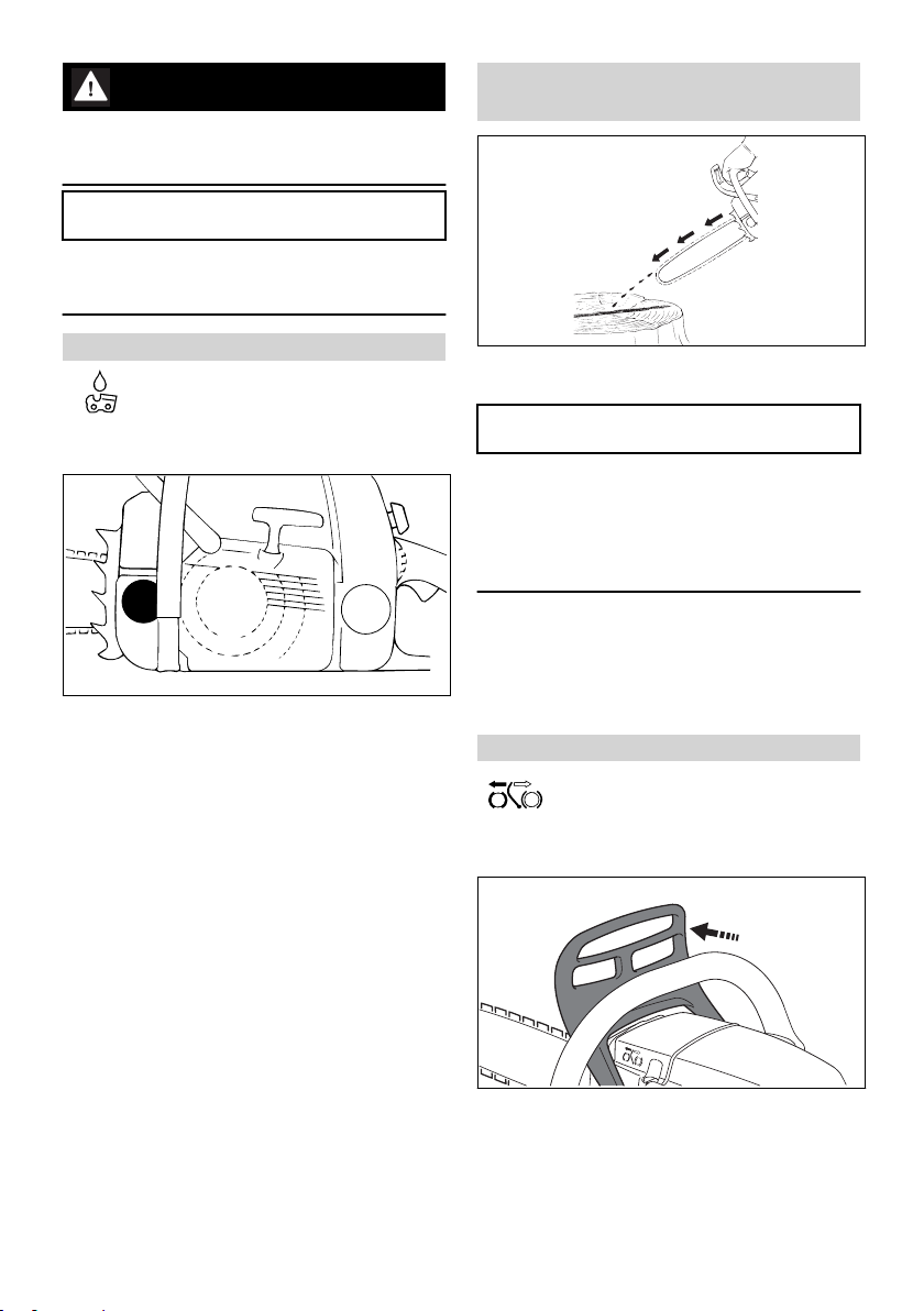
16 Chain Brake
16.1 Saw chain, lock
in an emergency
–
when starting
–
when idling
–
Press the hand guard towards the nose of the
guide bar with the left hand - or automatically
0458-153-0121-D 23
143BA012 KN
5902BA002 KN
5902BA003 KN
1
English 17 Winter Operation
due to kickback: Saw chain is blocked - and
stops running.
16.2 Disengage the chain brake.
Part-time use: every six months
occasional use: annually
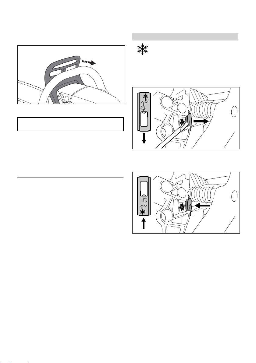
17 Winter Operation
17.1 Preheating the carburetor
► Remove the shroud – see "Shroud".
17.1.1 At temperatures below +10°C
► Pull the hand guard back towards the front
handle.
NOTICE
The chain brake must be released before open‐
ing the throttle (except during functional check‐
out) and before sawing.
Running the engine at high revs with the chain
brake engaged (chain locked) will quickly dam‐
age the engine and chain drive (clutch, chain
brake).
The chain brake is also activated by the inertia of
the front hand guard if the kickback force of the
saw is high enough: The hand guard is acceler‐
ated toward the bar nose – even if your left hand
is not behind the hand guard, e.g. during felling
cut.
The chain brake will operate only if the hand
guard has not been modified in any way.
16.3 Checking Operation of the
Chain Brake
Before starting work: Run engine at idle speed,
engage the chain brake (push hand guard
towards bar nose) and open the throttle wide for
(no more than 3 seconds) – the chain must not
rotate. The hand guard must be free of dirt and
easily moveable.
16.4 Chain Brake Maintenance
The chain brake is subject to (normal wear). It is
necessary to have it serviced and maintained
regularly by trained personnel. STIHL recom‐
mends that maintenance and repair work be car‐
ried out only by authorised STIHL dealers. The
following intervals must be complied with:
Full-time use: quarterly
24 0458-153-0121-D
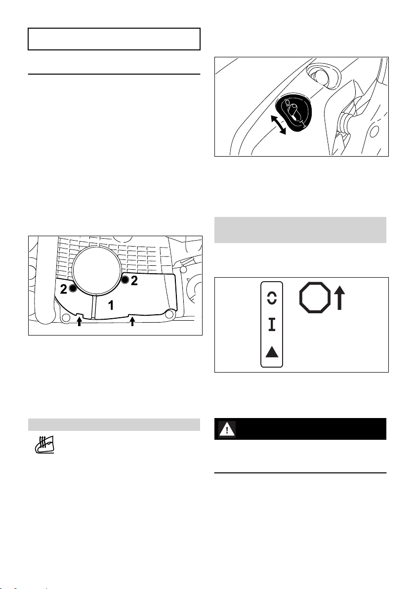
► Use the combination wrench or a screwdriver
to ease the shutter out of the summer posi‐
tion s.
► Refit the shutter the other way round in the
winter position – the arrow points to the sym‐
bol r – the shutter must snap into position.
The arrowhead (1) is visible in the winter posi‐
tion.
► Install the shroud – see "Shroud".
Heated air is now drawn in from around the cylin‐
der to warm the carburetor – this helps prevent
carburetor icing.
17.1.2 At temperatures above +20°C
►
Return the shutter to the summer position s .
5902BA004 KN
5902BA041 KN
5902BA042 KN
STOP
18 Electric Handle Heating English
NOTICE
This is important to reduce the risk of engine run‐
ning problems and overheating.
18.1 Switching on handle heating (depending on model)
17.2 At temperatures below -10°C
It is advisable to fit the "cover plate" kit (special
accessory) if you use your saw in extremely cold
conditions (temperatures below -10°C, in powder
or drifting snow).
The cover plate (special accessory) helps pre‐
vent snow being sucked into the machine.
When the cover plate is fitted, the shutter must
be in the winter position.
In the event of engine running problems, first
check that conditions for use of the cover plate
still apply.
17.2.1 Fitting the cover plate
►
Move the switch to F – move switch back to 0
to switch off.
There is no risk of overheating during long peri‐
ods of operation. The heating system is mainte‐
nance-free.
19 Starting / Stopping the
Engine
19.1 Positions of the Master Control lever
► Place the cover plate (1) in position, engage
the two tabs (arrows), and secure it with the
screws (2).
When the cover plate is fitted, the shutter must
be in the winter position.
If engine running problems occur, check that
conditions for use of the cover plate still apply.
18 Electric Handle Heating
0458-153-0121-D 25
STOP or † – Master Control lever must be
pushed in direction of STOP or † to switch off
ignition. The Master Control lever springs back to
the run position F when it is released.
WARNING
The ignition is switched on again automatically
after the engine stops. The engine can be star‐
ted at any time by actuating the starter.
Run position
position or the engine runs in this position.
Start position } – a cold engine is started in this
position.
F – a hot engine is started in this

5902BA043 KN
0001BA018 KN
0001BA019 KN
5902BA006 KN
English 19 Starting / Stopping the Engine
19.2 Adjust Master Control lever
To move the Master Control lever from the run
position F to start }, depress the trigger lockout
► Hold the front handle firmly with your left hand
– your thumb should be under the handle.
19.4 Actuating
and the throttle trigger and hold them in that
position – set the Master Control lever to start }
and let go of the throttle trigger and trigger lock‐
out.
The Master Control lever moves from the start
position } to the run position F when you press
down the throttle trigger lockout and squeeze the
throttle trigger at the same time.
To switch off the engine, move the Master Con‐
trol lever in the direction of STOP or † – when
released, the Master Control lever springs back
to the run position F.
19.3 Holding the Chain Saw
There are two methods of starting the saw.
19.3.1 On the ground
► Pull the starter grip slowly with your right hand
until you feel it engage – and then give it a
brisk strong pull and push down the front han‐
dle at the same time. Do not pull out the
starter rope to full length – it might otherwise
break. Do not let the starter grip snap back.
Guide it slowly back into the housing so that
the starter rope can rewind properly.
Machines without additional manual fuel pump: If
the engine is new or after a long out-of-service
period or if the tank has been run dry (engine
stops), it may be necessary to pull the starter
rope several times to prime the fuel system.
19.5 Starting the Chainsaw
19.5.1 Decompression valve
► Place your saw on the ground. Make sure you
have a firm footing – check that the chain is
not touching any object or the ground.
► Hold the saw firmly on the ground with your
left hand on the front handle – your thumb
should be under the handle.
► step into the rear handle with the right foot or
step on the rear hand guard with the heel of
the right foot
19.3.2 Between knees
► Press the button, the decompression valve will
be opened
The decompression valve closes as soon as the
engine fires. For this reason you must press in
the button before each starting attempt.
► clamp the rear handle between the knees or
thighs
26 0458-153-0121-D
4
2
4
3
1
5902BA047 KN
2
3
4
4
5902BA048 KN
001BA186 KN
5902BA049 KN
STOP
19 Starting / Stopping the Engine English
WARNING
Bystanders must be well clear of the general
work area of the saw.
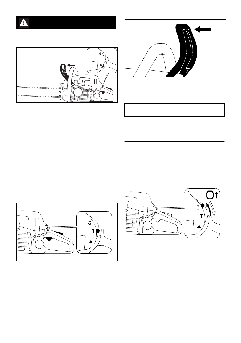
► Pull the hand guard back towards the front
handle.
The chain brake is now disengaged – your saw is
ready for operation.
► Push the hand guard (1) forward – the chain is
locked.
The Master Control lever (4) is in the normal run
position F.
► If the engine is cold: Press down the trigger
lockout (2) and pull the throttle trigger (3) at
the same time. Hold both levers in that posi‐
tion and set the Master Control lever (4) to
start symbol }
► Holding the chainsaw
► Pull the starter grip quickly and firmly as often
as necessary until the engine starts
► If the engine does not start: Move the Master
Control lever to start position } and repeat
starting procedure.
NOTICE
Open the throttle only when the chain brake is
off. Increased engine speeds with the chain
brake on (saw chain is stationary) will quickly
damage the clutch and chain brake.
19.7 At Very Low Outside Tempera‐
tures
► if necessary, configure for winter operation,
see "Winter Operation"
19.8 Shut off the engine
19.6 As Soon As the Engine Runs
► Move the Master Control lever in the direction
of STOP or † – when released, the Master
Control lever springs back to the normal run
► If the engine was started in the start posi‐
tion }: Press down trigger lockout (2) and the
pull the throttle trigger (3) at the same time –
the Master Control lever (4) moves to the run
position F and the engine settles down to idling
speed.
0458-153-0121-D 27
position F.
19.9 If Engine Does Not Start
► check whether all the controls are set correctly
► check whether there is fuel in the tank and
refuel if necessary
► Check whether the spark plug boot is connec‐
ted securely
► Repeat the starting procedure
or:

001BA157 KN
1
English 20 Operating Instructions
There is possibly a non-combustible fuel-air mix‐
ture in the combustion chamber of the engine
that is too rich– the engine has flooded.
► Remove the spark plug – see "Spark Plug".
► Dry the spark plug
► Keep the chain saw on the ground
► Push the Master Control lever as far as stop in
direction of STOP or † and hold it there.
WARNING
An ignition spark may occur if the Master Control
lever is not held against STOP or †.
► Actuate the starter several times
► Release the Master Control lever – it springs
back to the run position F.
► Refit the spark plug – see "Spark Plug".
► Hold and start your saw as described.
20 Operating Instructions
20.1 During the break-in period
A factory new machine should not be run at high
revs (full throttle off load) for the first three tank
fillings. This avoids unnecessarily high loads dur‐
ing the break-in period. As all moving parts have
to bed in during the break-in period, the frictional
resistances in the shortblock are greater during
this period. The engine develops its maximum
power after about 5 to 15 tank fillings.
20.2 During work
NOTICE
Open the throttle only when the chain brake is
off. Running the engine at high revs with the
chain brake engaged (chain locked) will quickly
damage the engine and chain drive (clutch,
chain brake).
20.2.1 Check chain tension frequently
A new saw chain must be retensioned more fre‐
quently than one that has been in use already for
an extended period.
20.2.2 Chain cold
Tension is correct when the chain fits snugly
against the underside of the bar but can still be
pulled along the bar by hand. Retension if neces‐
sary – see "Tensioning the Saw Chain".
20.2.3 Chain at operating temperature
The chain stretches and begins to sag. The drive
links must not come out of the bar groove on the
underside of the bar – the chain may otherwise
jump off the bar. Retension the chain – see "Ten‐
sioning the Saw Chain".
NOTICE
The chain contracts as it cools down. If it is not
slackened off, it can damage the crankshaft and
bearings.
20.2.4 After a long period of full-throttle oper‐
ation
After a long period of full-throttle operation, allow
engine to run for a while at idle speed so that the
heat in the engine can be dissipated by flow of
cooling air. This protects engine-mounted com‐
ponents (ignition, carburetor) from thermal over‐
load.
20.3 After finishing work
► Slacken off the chain if you have retensioned it
at operating temperature during work.
NOTICE
Always slacken off the chain again after finishing
work. The chain contracts as it cools down. If it is
not slackened off, it can damage the crankshaft
and bearings.
20.3.1 Short-term storage
Wait for engine to cool down. Keep the machine
with a full tank of fuel in a dry place, well away
from sources of ignition, until you need it again.
20.3.2 Long-term storage
See "Storing the machine"
21 Oil Quantity Control
Adjustable flow oil pump is a special option.
Different quantities of oil are required for different
bar lengths, types of wood and cutting techni‐
ques.
28 0458-153-0121-D

3
1
2
143BA026 KN
1
1
1
001BA199 KN
2
5902BA008 KN
22 Taking Care of the Guide Bar English
Use the adjusting screw (1) (on underside of
machine) to vary the oil feed rate as required.
Ematic position (E), medium oil flow rate –
► turn the adjusting screw to "E" (Ematic posi‐
tion).
To increase oil feed –
► turn the adjusting screw clockwise.
Turn reduce oil feed –
► turn the adjusting screw counterclockwise.
NOTICE
The chain must always be wetted with a film of
lubricant.
22 Taking Care of the Guide
Bar
► Turn the guide bar over – every time you
sharpen the chain and every time you replace
the chain – this helps avoid one-sided wear,
especially at the nose and underside of the
bar.
► Regularly clean the oil inlet hole (1), the oil‐
way (2) and the bar groove (3)
► Measure the groove depth – with the scale on
the filing gauge (special accessory) – in the
area used most for cutting
Chain type Chain pitch Minimum
Picco 1/4" P 4.0 mm
Rapid 1/4“ 4.0 mm
Picco 3/8" P 5.0 mm
Rapid 3/8“; 0.325“ 6.0 mm
Rapid 0.404“ 7.0 mm
If groove depth is less than specified:
► Replace the guide bar
The drive link tangs will otherwise scrape along
the bottom of the groove – the cutters and tie
straps will not ride on the bar rails.
groove
depth
23 Shroud
23.1 Removing the Shroud
► To switch off the engine, move the Master
Control lever in the direction of STOP or † –
when released, the Master Control lever
springs back to the run position F.
► Push the hand guard forward – the chain is
locked.
► Open the twist locks (1) by turning them 1/4
turn counterclockwise with the combination
wrench.
► Remove the shroud (2).
23.2 Installing the Shroud
► Place the shroud in position.
► Close the twist locks by turning them a 1/4
turn clockwise.
24 Air Filter System
The air filter system can be adapted to suit differ‐
ent operating conditions by installing different fil‐
ters. Changing a filter is accomplished quickly
and simply.
► HD2 Filter Universal filter for almost all operat‐
ing conditions (from very dusty to very cold)
0458-153-0121-D 29

5902BA009 KN
1.
5902BA010 KN
2.
5902BA011 KN
2.
1.
Andreas Stihl AG & Co. KG
XXXX XXX XXXX X M3.0
0000-GXX-3485-A0
English 25 Cleaning the Air Filter
► Rinse outside of filter under warm running
water.
NOTICE
Allow air filter to dry without using any external
–
source of heat.
Do not impregnate the filter with oil.
–
► Allow air filter to dry.
► Install the air filter.
25.1.3 Installing the Air Filter
► Synthetic fabric filter: For use in severe condi‐
tions, e.g. extreme wintry operating conditions
- such as powdery or drifting snow. Less suita‐
ble for very dusty conditions.
STIHL filters have a long service life in dry oper‐
ating conditions.
► Always use STIHL filters in dry state.
Dirty air filters reduce engine power, increase
fuel consumption and make starting more diffi‐
cult.
25 Cleaning the Air Filter
25.1 If There is a Noticeable Loss of
Engine Power
► Remove the shroud – see "Shroud".
► Place the air filter in position.
► Push the air filter towards the filter housing
and turn it clockwise at the same time until it
engages – the "STIHL" name must be horizon‐
tal.
► Install the shroud – see "Shroud".
25.1.1 Removing the Air Filter
► Clean away loose dirt from around the filter.
NOTICE
To avoid damaging the filter, do not use tools to
remove or install the air filter.
26 M-Tronic
During operation the chain saw automatically
adjusts to the optimum power.
Depending on the STIHL M‑Tronic version the
chain saw can be adjusted more quickly to the
optimum power in two different ways:
“Speeding up automatic adaptation of the
–
chain saw”
“Calibrating the chain saw”
–
► Rotate the air filter a 1/4 turn counterclockwise
and lift it away in the direction of the rear han‐
dle.
► Always replace damaged filters.
25.1.2 Cleaning the Air Filter
► Knock out the filter.
► Spray outside of filter with STIHL special
cleaner or soapy water.
The STIHL M‑Tronic version is indicated on the
approval label of the chain saw, e.g. "M3.0" indi‐
cates the STIHL M‑Tronic version 3.0.
30 0458-153-0121-D

1
min
AB C
s> 30 s30-60 s
0000-GXX-4580-A0
27 Spark Plug English
► If the STIHL M‑Tronic version is lower than
3.0: “Speeding up automatic adaptation of the
chain saw”.
► If the STIHL M‑Tronic version is 3.0 or higher:
“Calibrating the chain saw”.
26.1 Speeding Up Automatic Adap‐
tation of the Chain Saw
► Carry out five uniform cuts to length at full
throttle.
26.2 Calibrating the Chain Saw
If the external temperature is below -10°C or the
engine is cold:
► Start engine and release chain brake.
► Warm up engine for about 1 minute by blip‐
ping the throttle.
► Switch off engine.
To calibrate the chain saw, carry out the follow‐
ing steps:
►
Set master control lever to } position.
► Engage chain brake.
► Start engine without depressing the throttle
trigger. The engine runs and the master con‐
trol lever remains in the } position.
► Allow engine to run for at least 30 to max.
60 seconds (A) without depressing the throttle
trigger.
WARNING
The saw chain may rotate when the chain brake
is released ‑ risk of injury!
Hold the chain saw as described in the Instruc‐
tion Manual and do not touch the moving saw
chain.
► Release chain brake.
NOTICE
If the throttle trigger is released before the chain
saw has been fully calibrated, calibration will be
aborted. Calibration has to be started again from
the beginning.
► Fully depress throttle trigger and hold it there.
NOTICE
If the throttle trigger is not fully depressed during
calibration, the chain saw may not adjust cor‐
rectly. The chain saw may be damaged.
► Fully depress throttle trigger and hold it there.
► Depress and hold down throttle trigger for at
least 30 seconds (B).
The engine accelerates and the saw chain
rotates. The chain saw is being calibrated. The
engine speed fluctuates and increases percepti‐
bly during calibration.
If the engine stops:
► try again to calibrate the chain saw.
If the engine repeatedly stops:
► Engage chain brake.
► Do not use the chain saw. Consult a STIHL
servicing dealer. The chain saw has a fault.
As soon as the engine speed audibly and per‐
ceptibly drops (C):
► Release throttle trigger.
The engine idles. The chain saw is calibrated
and ready for use.
27 Spark Plug
► If the engine is down on power, difficult to start
or runs poorly at idle speed, first check the
spark plug.
► Fit a new spark plug after about 100 operating
hours – or sooner if the electrodes are badly
eroded. Install only suppressed spark plugs of
the type approved by STIHL – see "Specifica‐
tions".
27.1 Removing the Spark Plug
► Remove the shroud – see "Shroud".
0458-153-0121-D 31
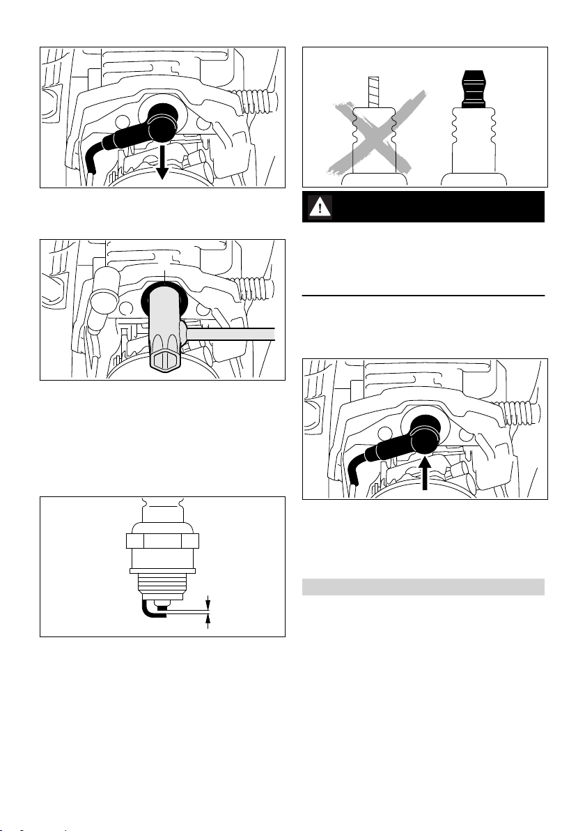
5902BA013 KN
5902BA014 KN
1
000BA039 KN
A
1
000BA045 KN
5902BA016 KN
English 28 Storing the Machine
► Pull off the spark plug boot.
► Clean away loose dirt from around the spark
plug.
► Insert the combination wrench through the
grommet (1) and turn it as necessary to
engage the spark plug's hexagon.
► Push the combination fully home against the
cylinder.
► Unscrew the spark plug.
27.2 Checking the Spark Plug
► Clean dirty spark plug.
► Check electrode gap (A) and readjust if neces‐
sary – see "Specifications".
► Rectify the problems which have caused foul‐
ing of the spark plug.
Possible causes are:
Too much oil in fuel mix.
–
Dirty air filter.
–
Unfavorable running conditions.
–
WARNING
Arcing may occur if the adapter nut (1) is loose
or missing. Working in an easily combustible or
explosive atmosphere may cause a fire or an
explosion. This can result result in serious inju‐
ries or damage to property.
► Use resistor type spark plugs with a properly
tightened adapter nut.
27.3 Installing the spark plug
► Insert the spark plug through the grommet and
screw it in by hand.
► Tighten down the spark plug, fit the boot and
press it down firmly.
► Install the shroud – see "Shroud".
28 Storing the Machine
For periods of about 30 days or longer
► Drain and clean the fuel tank in a well-ventila‐
ted area.
► Dispose of fuel properly in accordance with
local environmental requirements.
► If a manual fuel pump is fitted: Press the man‐
ual fuel pump at least 5 times.
► Start the engine and run it at idling speed until
it stops.
► Remove saw chain and guide bar; clean and
spray with protective oil
► Thoroughly clean the machine - pay special
attention to the cylinder fins and air filter
32 0458-153-0121-D
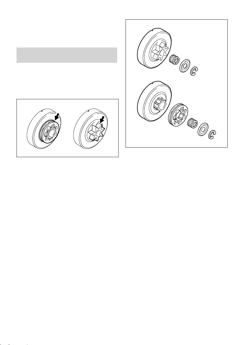
001BA121 KN
001BA122 KN
1
2
4
5
6
1
2
3
6
29 Checking and Replacing the Chain Sprocket English
► When using biological chain oil (e.g. STIHL
BioPlus), fill the lubricant oil tank
► Store the machine in a dry and secure location
Keep out of the reach of children and other
unauthorized persons
29 Checking and Replacing
the Chain Sprocket
► Remove chain sprocket cover, saw chain and
guide bar.
► Release chain brake – pull hand guard against
the front handle
29.1 Fit new chain sprocket
► Use a screwdriver to remove the E-clip (1)
after use of two saw chains or earlier
–
if the wear marks (arrows) are deeper than
–
0.5 mm – otherwise the service life of the saw
chain is reduced – use check gauge (special
accessory) to test
Using two saw chains in alternation helps pre‐
serve the chain sprocket.
STIHL recommends use of original STIHL chain
sprockets in order to ensure optimal functioning
of the chain brake.
► Remove the washer (2)
► Remove rim sprocket (3)
► Inspect transport profile on the clutch drum (4)
– if there are also heavy signs of wear, also
replace the clutch drum
► Remove clutch drum or spur chain
sprocket (5) including needle cage (6) from the
crankshaft – with QuickStop Super chain
brake, press throttle trigger lockout before‐
hand
29.2 Install spur chain sprocket / rim
sprocket
► Clean crankshaft stub and needle cage and
lubricate with STIHL lubricant (special acces‐
sory)
► Slide needle cage onto the crankshaft stub
► After refitting, turn the clutch drum and/or spur
chain sprocket approx. 1 full turn so that the
carrier for the oil pump drive engages – with
QuickStop Super chain brake, press throttle
trigger lockout beforehand
► Refit the rim sprocket – cavities toward the
outside
► Refit washer and E-clip on the crankshaft
0458-153-0121-D 33
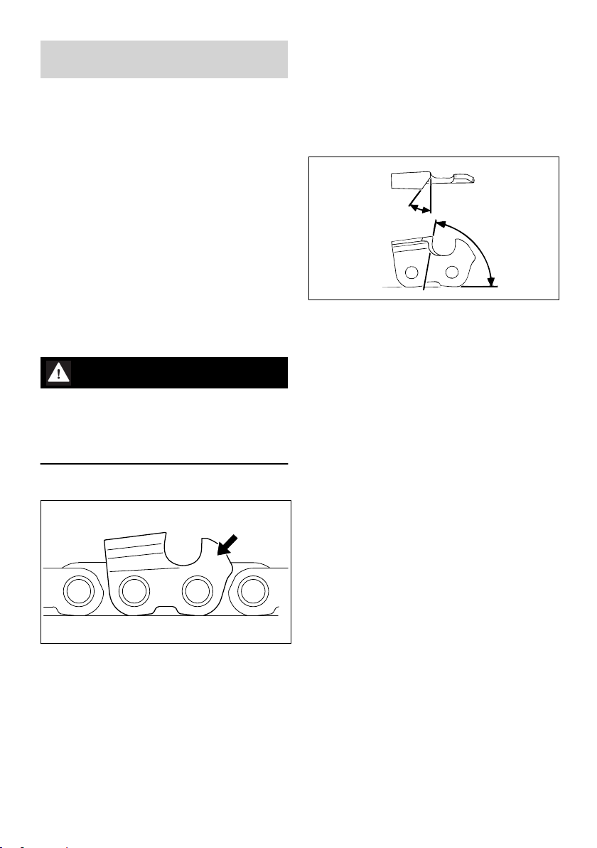
689BA027 KN
a
A
B
689BA021 KN
English 30 Maintaining and Sharpening the Saw Chain
30 Maintaining and Sharpen‐
ing the Saw Chain
30.1 Sawing effortlessly with a prop‐
erly sharpened saw chain
A properly sharpened saw chain cuts through
wood effortlessly even with very little pushing.
Never use a dull or damaged saw chain – this
leads to increased physical strain, increased
vibration load, unsatisfactory cutting results and
increased wear.
► Clean the saw chain
► Check the saw chain for cracks and damaged
rivets
► Replace damaged or worn chain components
and adapt these parts to the remaining parts in
terms of shape and level of wear – rework
accordingly
Carbide-tipped (Duro) saw chains are especially
wear-resistant. For an optimal sharpening result,
STIHL recommends STIHL servicing dealers.
WARNING
Compliance with the angles and dimensions lis‐
ted below is absolutely necessary. An improperly
sharpened saw chain – especially depth gauges
that are too low – can lead to increased kickback
tendency of the chain saw – risk of injury!
30.2 Chain pitch
The diameter of file to be used depends on the
chain pitch – see table "Sharpening tools".
The angles of the cutter must be maintained dur‐
ing resharpening.
30.3 Sharpening and side plate angles
A Sharpening angle
STIHL saw chains are sharpened with a 30°
sharpening angle. Ripping chains, which are
sharpened with a 10° sharpening angle, are
exceptions. Ripping chains have an X in the des‐
ignation.
B Side plate angle
The correct side plate angle results automatically
when the specified file holder and file diameter
are used.
Tooth shapes Angle (°)
A B
Micro = semi-chisel tooth, e. g.,
63 PM3, 26 RM3, 36 RM
Super = full chisel tooth, e. g.,
63 PS3, 26 RS, 36 RS3
Ripping chain, e. g., 63 PMX,
36 RMX
The angles must be identical for all cutters in the
saw chain. Varying angles: Rough, uneven run‐
ning of the saw chain, increased wear – even to
the point of saw chain breakage.
30 75
30 60
10 75
The chain pitch marking (a) is embossed in the
area of the depth gauge of each cutter.
Marking (a) Chain pitch
Inches mm
7 1/4 P 6.35
1 or 1/4 1/4 6.35
6, P or PM 3/8 P 9.32
2 or 325 0.325 8.25
3 or 3/8 3/8 9.32
4 or 404 0.404 10.26
34 0458-153-0121-D
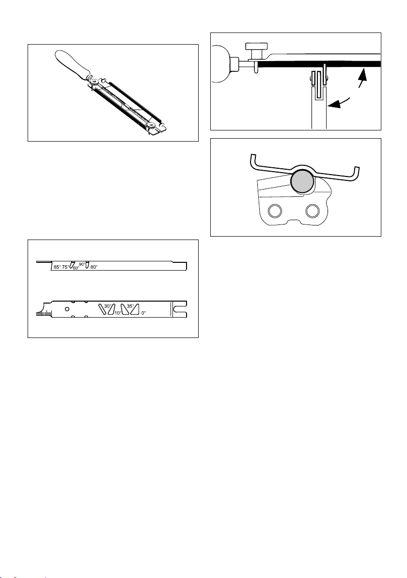
689BA025 KN
001BA203 KN
689BA018 KN
90°
689BA043 KN
30 Maintaining and Sharpening the Saw Chain English
30.4 File holder
► Use a file holder
Always use a file holder (special accessory, see
table "Sharpening tools") when sharpening saw
chains by hand. File holders have markings for
the sharpening angle.
Use only special saw chain files! Other files are
unsuitable in terms of shape and type of cutting.
30.5 To check the angles
► Guide the file: horizontally (at a right angle to
the side surface of the guide bar) in accord‐
ance with the specified angle – according to
the markings on the file holder – rest the file
holder on the tooth head and the depth gauge
► File only from the inside outward
► The file only sharpens on the forward stroke –
lift the file on the backstroke
► Do not file tie straps and drive links
► Rotate the file a little periodically in order to
avoid uneven wear
STIHL filing gauge (special accessory, see table
"Sharpening tools") – a universal tool for check‐
ing sharpening and side plate angles, depth
gauge setting, and tooth length, as well as clean‐
ing grooves and oil inlet holes.
30.6 Proper sharpening
► Select sharpening tools in accordance with
chain pitch
► Clamp guide bar if necessary
► Block saw chain – push the hand guard for‐
ward
► To advance the saw chain, pull the hand
guard toward the handlebar: The chain brake
is disengaged. With the Quickstop Super
chain brake system, additionally press the
throttle trigger lockout
► Sharpen frequently, removing little material –
two or three strokes of the file are usually suffi‐
cient for simple resharpening
► To remove file burr, use a piece of hardwood
► Check angle with file gauge
All cutters must be equally long.
With varying cutter lengths, the cutter heights
also vary and cause rough running of the saw
chain and chain breakage.
► All cutters must be filed down equal to the
length of the shortest cutter – ideally, one
should have this done by a servicing dealer
using an electric sharpener
0458-153-0121-D 35

689BA023 KN
a
2
689BA061 KN
1
689BA051 KN
689BA044 KN
689BA052 KN
English 30 Maintaining and Sharpening the Saw Chain
30.7 Depth gauge setting
The depth gauge determines the depth to which
the cutter penetrates the wood and thus the chip
thickness.
a Required distance between depth gauge and
cutting edge
mark) is lowered at the same time as the depth
gauge of the cutter.
WARNING
The rest of the humped drive link must not be
filed; otherwise, this could increase the tendency
of the chain saw to kick back.
When cutting softwood outside of the frost sea‐
son, the distance can be increased by up to
0.2 mm (0.008").
Chain pitch Depth gauge
Distance (a)
Inches (mm) mm (Inches)
1/4 P (6.35) 0.45 (0.018)
1/4 (6.35) 0.65 (0.026)
3/8 P (9.32) 0.65 (0.026)
0.325 (8.25) 0.65 (0.026)
3/8 (9.32) 0.65 (0.026)
0.404 (10.26) 0.80 (0.031)
30.8 Lowering the depth gauges
The depth gauge setting is lowered when the
cutter is sharpened.
► Check the depth gauge setting after each
sharpening
► Lay the appropriate file gauge (1) for the chain
pitch on the saw chain and press it against the
cutter to be checked – if the depth gauge pro‐
trudes past the file gauge, the depth gauge
must be reworked
Saw chains with humped drive link (2) – upper
part of the humped drive link (2) (with service
► Rework the depth gauge so that it is flush with
the file gauge
► Afterwards, dress the leading edge of the
depth gauge parallel to the service mark (see
arrow) – when doing this, be careful not to fur‐
ther lower the highest point of the depth gauge
WARNING
Depth gauges that are too low increase the kick‐
back tendency of the chain saw.
36 0458-153-0121-D

31 Maintenance and Care English
► Lay the file gauge on the saw chain – the high‐
est point of the depth gauge must be flush with
the file gauge
► After sharpening, clean the saw chain thor‐
oughly, removing any filings or grinding dust –
lubricate the saw chain thoroughly
► In the event of extended periods of disuse,
store saw chains in cleaned and oiled condi‐
tion
Sharpening tools (special accessories)
Chain pitch Round file^Round file File holder File gauge Taper square
file
Sharpening
1)
set
Inches (mm) mm (Inches)Part number Part number Part number Part number Part number
1/4P (6.35) 3.2 (1/8) 5605 771
3206
5605 750
4300
0000 893
4005
0814 252
3356
5605 007
1000
1/4 (6.35) 4.0 (5/32) 5605 772 40065605 750 43271110 893 40000814 252 33565605 007
1027
3/8 P (9.32) 4.0 (5/32) 5605 772
4006
0.325 (8.25) 4.8 (3/16) 5605 772
4806
3/8 (9.32) 5.2 (13/64) 5605 772
5206
0.404 (10.26) 5.5 (7/32) 5605 772
5506
1)
consisting of file holder with round file, taper square file and file gauge
5605 750
4327
5605 750
4328
5605 750
4329
5605 750
4330
1110 893
4000
1110 893
4000
1110 893
4000
1106 893
4000
0814 252
3356
0814 252
3356
0814 252
3356
0814 252
3356
5605 007
1027
5605 007
1028
5605 007
1029
5605 007
1030
31 Maintenance and Care
The following information applies in normal operat‐
ing conditions. The specified intervals must be
shortened accordingly when working for longer
than normal or under difficult cutting conditions
(extensive dust, highly resinous lumber, lumber
from tropical trees, etc.). If you only use the tool
occasionally, extend the intervals accordingly.
Weekly
Monthly
If faulty
Annually
If damaged
As required
Before starting work
Whenever tank is refilled
At the end of work and/or daily
Complete machine Visual inspection (condi‐
X X
tion, leaks)
Clean X
Throttle trigger, throttle
Function test X X
trigger lockout, choke
lever, stop switch, master
control lever (dependent
on equipment)
Chain brake Function test X X
Manual fuel pump (if
present)
Have checked by
1)
dealer
check X
Have repaired by a spe‐
cialist dealer
1)
X
X
0458-153-0121-D 37

English 31 Maintenance and Care
The following information applies in normal operat‐
ing conditions. The specified intervals must be
shortened accordingly when working for longer
than normal or under difficult cutting conditions
(extensive dust, highly resinous lumber, lumber
from tropical trees, etc.). If you only use the tool
Weekly
Monthly
If faulty
Annually
If damaged
As required
occasionally, extend the intervals accordingly.
Before starting work
Whenever tank is refilled
Fuel pick-up body / filter
in fuel tank
check X
Clean, replace filter
X X
insert
replace X X X
Fuel tank Clean X
Lubricating oil tank Clean X
Chain lubrication check X
At the end of work and/or daily
Saw chain Check, pay attention to
X X
sharpness
Checking the chain ten‐
X X
sion
sharpen X
Guide bar Check (wear, damage) X
Clean and turn over X
Deburr X
replace X X
Chain sprocket check X
Air filter Clean X X
replace X
Anti-vibration elements check X X
Have replaced by serv‐
icing dealer
1)
X
Air intake on fan housing Clean X X X
Cylinder fins Clean X X X
Carburetor Check idle adjustment –
X X
saw chain must not
rotate
If the saw chain contin‐
X
ues moving when the
engine is idling, have
your chainsaw checked
and repaired by your
1)
dealer
Spark plug Adjust electrode gap X
Replace after 100 hours
of operation
Accessible screws, nuts
and bolts
Tighten
2)
Chain catcher check X
X
X
38 0458-153-0121-D

32 Minimize Wear and Avoid Damage English
The following information applies in normal operat‐
ing conditions. The specified intervals must be
shortened accordingly when working for longer
than normal or under difficult cutting conditions
(extensive dust, highly resinous lumber, lumber
from tropical trees, etc.). If you only use the tool
occasionally, extend the intervals accordingly.
Weekly
Before starting work
Whenever tank is refilled
Monthly
If faulty
Annually
If damaged
As required
At the end of work and/or daily
replace
Safety information label replace X
1)
STIHL recommends STIHL dealers
2)
Firmly tighten down the cylinder base screws of chainsaws (3.4 kW or more) after 10 to 20 hours of
operation.
32 Minimize Wear and Avoid
Damage
Compliance with the specifications of this
Instruction Manual will avoid excessive wear and
damage to the machine.
The machine must be used, maintained and
stored as carefully as described in this Instruc‐
tion Manual.
The user is responsible for all damage caused by
failure to comply with the safety, operating and
maintenance instructions. This applies in particu‐
lar for:
Product modifications not authorized by STIHL
–
Use of tools or accessories that are not
–
approved for the machine, unsuitable or of
inferior quality
Use of the machine in a manner not in keeping
–
with the intended use
Use of the machine in sporting events or com‐
–
petitions
Consequential damages due to continued use
–
of a machine with defective components
32.1 Maintenance work
All of the tasks listed under "Maintenance and
Care" must be carried out periodically. If the user
does not carry out these maintenance tasks himor herself, they should be delegated to a dealer.
STIHL recommends that maintenance and repair
work be carried out only by authorized STIHL
dealers. STIHL dealers receive regular training
and are supplied with technical information.
If these tasks are not performed or are per‐
formed improperly, this may result in damage for
which the user is responsible. These include,
among others:
Engine damage due to delayed or insufficient
–
maintenance (e. g., air and fuel filters) or insuf‐
ficient cleaning of the cooling air routing (air
intake slits, cylinder fins)
Corrosion damage and other consequential
–
damages due to improper storage
Damage to the machine as a result of using
–
replacement parts of inferior quality
32.2 Parts Subject to Wear and Tear
Some parts of the power tool are subject to nor‐
mal wear and tear even during regular operation
in accordance with instructions and, depending
on the type and duration of use, have to be
replaced in good time. Among other parts, this
includes:
Saw chain, guide bar
–
Drive components (clutch, clutch drum, chain
–
sprocket)
Filters (air, oil, fuel)
–
Starter mechanism
–
Spark plug
–
Components of antivibration system
–
X
0458-153-0121-D 39
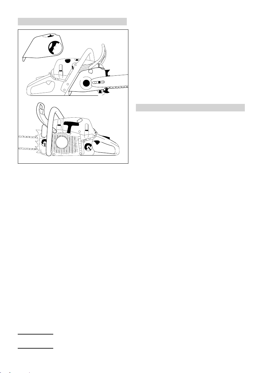
22
27
23
25
26
24
17
20
21
10
5
1
1
14
16
4
11
9
2, 3
5902BA054 KN
7
12
13
8
18
19
1
6
#
8
15
English 33 Main Parts
33 Main Parts
20 Spark plug boot
21 Starter grip
22 Fuel filler cap
23 Master Control lever
24 Throttle trigger
25 Throttle trigger lockout
26 Rear handle
27 Rear hand guard
# Serial number
34 Specifications
34.1 Engine
STIHL single-cylinder two-stroke engine
Displacement:
Cylinder bore: 44.7 mm
Piston stroke: 32 mm
Engine power to ISO 7293: 3.0 kW (4.1 hp) at
Idle speed:
1 Shroud lock
2
Handle heating switch
3
Decompression valve
4
Manual fuel pump
1)
1)
1)
5 Shutter (summer and winter operation)
6 Chain brake
7 Chain sprocket
8 Chain sprocket cover
9 Chain catcher
10
Side chain tensioner
11 Spiked bumper
12 Guide bar
13 Oilomatic chain
14
15
Adjusting wheel1) (quick chain adjuster)
Handle of wingnut
16 Oil filler cap
17 Muffler
18 Front hand guard
19 Front handle (handlebar)
1)
1)
40 0458-153-0121-D
Depending on model
according to ISO 11681 +/- 50 1/min
1)
1)
(quick chain adjuster)
34.2 Ignition system
Electronic magneto ignition
Spark plug (suppressed): Bosch WSR 6 F,
Electrode gap: 0.5 mm
34.3 Fuel system
All-position diaphragm carburetor with integral
fuel pump
Fuel tank capacity:
34.4 Chain lubrication
Fully automatic, speed-controlled oil pump with
rotary piston. Additional manual oil flow control
Oil tank capacity:
34.5 Weight
dry, without cutting attachment
MS 261 C-M: 4.9 kg
MS 261 C-M with quick chain adjuster: 5.1 kg
MS 261 C-M with handle and carbu‐
retor heating:
1)
500 cm3 (0.5 l)
270 cm3 (0.27 l)
3
50.2cm
10000 1/min
2800 rpm
NGK BPMR 7 A
5.0 kg

35 Ordering Spare Parts English
34.6 Cutting attachment
The actual cutting length may be less than the
specified cutting length.
34.6.1 Rollomatic Light 04 guide bars
Bar lengths (pitch .325"): 35, 40, 45, 50 cm
Groove width: 1.3 mm
Sprocket nose: 10 tooth
34.6.2 Rollomatic Guide Bars
Bar lengths (pitch .325"): 40, 45, 50 cm
Groove width: 1.3 mm
Sprocket nose: 11 tooth
34.6.3 Rollomatic Light 04 guide bars
Bar lengths (pitch .325"): 35, 40, 45, 50 cm
Groove width: 1.6 mm
Sprocket nose: 10 tooth
34.6.4 Rollomatic Guide Bars
Bar lengths (pitch .325"): 32, 37, 40, 45 cm
Groove width: 1.6 mm
Sprocket nose: 11 tooth
34.6.5 Duromatic guide bars
Bar lengths (pitch .325"): 37, 40, 45 cm
Groove width: 1.6 mm
34.6.6 Saw chains .325"
Rapid Micro (23 RM) Type 3684
Rapid Micro 3 (23 RM3) Type 3687
Rapid Super (23 RS) Type 3637
Rapid Duro 3 (23 RD3) Type 3665
Rapid Micro Pro (23 RM Pro) 3693
Rapid Micro 3 Pro (23 RM3 Pro) 3695
Rapid Super Pro (23 RS Pro) 3690
Rapid Duro 3 Pro (23 RD3 Pro) 3696
Pitch: .325" (8.25 mm)
Drive link gauge: 1.3 mm
Rapid Micro (26 RM) Type 3686
Rapid Micro 3 (26 RM3) Type 3689
Rapid Super (26 RS) Type 3639
Pitch: .325" (8.25 mm)
Drive link gauge: 1.6 mm
34.6.7 Chain sprocket
7-tooth for .325"
Max. chain speed according to
ISO 11681:
Chain speed at maximum power:
25.6 m/s
19.3 m/s
34.7 Sound and Vibration Levels
For further details on compliance with Vibration
Directive 2002/44/EC, see
www.stihl.com/vib
34.7.1 Sound pressure level L
ance with ISO 22868
105 dB(A)
34.7.2 Sound power level Lw in accordance
with ISO 22868
116 dB(A)
34.7.3 Vibration level a
with ISO 22867
Handle, left:
Handle, right:
The K‑factor in accordance with Directive
2006/42/EC is 2.0 dB(A) for the sound pressure
level and sound power level; the K‑factor in
accordance with Directive 2006/42/EC is
2.0 m/s2 for the vibration level.
hv,eq
34.8 REACH
REACH is an EC regulation and stands for the
Registration, Evaluation, Authorization and
Restriction of Chemical substances.
For information on compliance with the REACH
regulation (EC) No. 1907/2006 see
www.stihl.com/reach
34.9 Exhaust Emissions
The CO2 value measured in the EU type appro‐
val procedure is specified at
www.stihl.com/co2
in the product-specific technical data.
The measured CO2 value was determined on a
representative engine in accordance with a
standardized test procedure under laboratory
conditions and does not represent either an
explicit or implied guarantee of the performance
of a specific engine.
The applicable exhaust emission requirements
are fulfilled by the intended usage and mainte‐
nance described in this User Manual. The oper‐
ating license shall be void if the engine is modi‐
fied in any way.
35 Ordering Spare Parts
Please enter your saw model, serial number as
well as the part numbers of the guide bar and
saw chain in the spaces provided. This will make
re-ordering simpler.
The guide bar and saw chain are subject to nor‐
mal wear and tear. When purchasing these
in accord‐
peq
in accordance
3.5 m/s
3.5 m/s
2
2
0458-153-0121-D 41

000BA073 KN
English 36 Maintenance and Repairs
parts, always quote the saw model, the part
numbers and names of the parts.
Model
Serial number
Guide bar part number
Chain part number
36 Maintenance and Repairs
Users of this machine may only carry out the
maintenance and service work described in this
user manual. All other repairs must be carried
out by a servicing dealer.
STIHL recommends that you have servicing and
repair work carried out exclusively by an author‐
ized STIHL servicing dealer. STIHL dealers are
regularly given the opportunity to attend training
courses and are supplied with the necessary
technical information.
When repairing the machine, only use replace‐
ment parts which have been approved by STIHL
for this power tool or are technically identical.
Only use high-quality replacement parts in order
to avoid the risk of accidents and damage to the
machine.
STIHL recommends the use of original STIHL
replacement parts.
Original STIHL parts can be identified by the
STIHL part number, the { logo and the
STIHL parts symbol K (the symbol may appear
alone on small parts).
37 Disposal
Contact the local authorities or your STIHL serv‐
icing dealer for information on disposal.
Improper disposal can be harmful to health and
pollute the environment.
► Take STIHL products including packaging to a
suitable collection point for recycling in accord‐
ance with local regulations.
► Do not dispose with domestic waste.
38 EC Declaration of Con‐
formity
ANDREAS STIHL AG & Co. KG
Badstr. 115
D-71336 Waiblingen
Germany
declares under our sole responsibility that
Designation: Chainsaw
Make: STIHL
Series: MS 261 C-M
Serial identification number: 1141
Displacement:
conforms to the relevant provisions of Directives
2011/65/EU, 2006/42/EC, 2014/30/EU and
2000/14/EC and has been developed and manu‐
factured in compliance with the following stand‐
ards in the versions valid on the date of produc‐
tion:
EN ISO 11681‑1, EN 55012, EN 61000‑6‑1
The measured and the guaranteed sound power
level have been determined in accordance with
Directive 2000/14/EC, Annex V, and standard
ISO 22868.
Measured sound power level
116 dB(A)
Guaranteed sound power level
118 dB(A)
The EC type examination was carried out by
DPLF
Deutsche Prüf- und Zertifizierungsstelle für Landund Forsttechnik GbR (NB 0363)
Spremberger Straße 1
D-64823 Groß-Umstadt
Certification No.:
K-EG -2009/5306
Technical documents deposited at:
ANDREAS STIHL AG & Co. KG
Produktzulassung
The year of manufacture and serial number are
applied to the product.
MS 261 C-MVW
MS 261 C-BM
MS 261 C-MQ
3
50.2 cm
42 0458-153-0121-D

39 UKCA Declaration of Conformity English
Done at Waiblingen, 03.02.2020
ANDREAS STIHL AG & Co. KG
pp
Dr. Jürgen Hoffmann
Director Product Certification & Regulatory
Affairs
39 UKCA Declaration of Con‐
formity
ANDREAS STIHL AG & Co. KG
Badstr. 115
D-71336 Waiblingen
Germany
declares under our sole responsibility that
Designation: Chainsaw
Make: STIHL
Series: MS 261 C-M
MS 261 C-MVW
MS 261 C-BM
MS 261 C-MQ
Serial identification number: 1141
Displacement:
conforms to the relevant provisions of UK regula‐
tions The Restriction of the Use of Certain Haz‐
ardous Substances in Electrical and Electronic
Equipment Regulations 2012, Supply of Machi‐
nery (Safety) Regulations 2008, Electromagnetic
Compatibility Regulations 2016 and Noise Emis‐
sion in the Environment by Equipment for use
Outdoors Regulations 2001 and has been manu‐
factured in compliance with the following stand‐
ards in the versions valid on the date of produc‐
tion:
EN ISO 11681‑1, EN 55012, EN 61000‑6‑1
The measured and the guaranteed sound power
level have been determined in accordance with
UK regulation Noise Emission in the Environ‐
ment by Equipment for use Outdoors Regula‐
tions 2001, Annex 8, using the ISO 22868 stand‐
ard.
Measured sound power level
116 dB(A)
50.2 cm
3
Guaranteed sound power level
118 dB(A)
The type examination was carried out by
Intertek Testing & Certification Ltd, Academy
Place, 1 – 9 Brook Street, Brentwood Essex,
CM14 5NQ, United Kingdom
Certification No.
ITS UK MCR 11
Technical documents deposited at:
ANDREAS STIHL AG & Co. KG
The year of manufacture and serial number are
applied to the product.
Waiblingen, 31.03.2022
ANDREAS STIHL AG & Co. KG
pp
Dr. Jürgen Hoffmann
Director Product Certification & Regulatory
Affairs
0458-153-0121-D 43

www.stihl.com
*04581530121D*
0458-153-0121-D
*04581530121D*
0458-153-0121-D
 Loading...