

Page 1

STIHL KW 85
Instruction Manual
Owner's Manual
Assembling
Safety Precautions
Operating Instructions
Maintenance
III
D
Page 2

Contents
english / USA
Allow only persons who understand this
Manual to operate your PowerSweep.
To receive maximum performance and
satisfaction from your STIHL
PowerSweep, it is important that you
read and understand the maintenance
and safety precautions, starting on
page 3, before using your PowerSweep.
Contact your STIHL dealer or the STIHL
distributor for your area if you do not
understand any of the instructions in this
Manual.
!Warning!
Because a PowerSweep is a power
tool, some special safety precautions
must be observed to reduce the risk of
personal injury.
Careless or improper use may cause
serious or even fatal injury.
Always wear proper eye protection.
STIHL's philosophy is to continually
improve all of its products. As a result,
engineering changes and improvements
are made from time to time. If the
operating characteristics or the
appearance of your PowerSweep differs
from those described in this Manual,
please contact your STIHL dealer for
information and assistance.
Printed on chlorine-free paper
Printing inks contain vegetable oils,
paper is recyclable
© 2001 Andreas Stihl AG & Co., Waiblingen
0458 223 3021. M0,25. C1. PM. Printed in USA
Guide to Using this Manual .............. 2
Safety Precautions and Working
Techniques ....................................... 3
Fitting Carrying Eye* (Clamp) ........ 10
Mounting the Loop Handle ............. 10
Installing the Gearbox ..................... 11
Mounting Sweeper Drums .............. 12
Fuel ................................................ 13
Fueling ........................................... 14
Attaching Machine to Harness* ...... 14
Starting ........................................... 15
Operating Instructions .................... 18
Using the PowerSweep .................. 18
Disconnecting Machine from
Harness .......................................... 19
Cleaning the Air Filter ..................... 20
Motor Management ........................ 21
Adjusting the Carburetor ................ 21
Adjusting the Carburetor ................ 22
Checking the Spark Plug ................ 24
Removing the Gearbox .................. 25
Replacing the
Rubber Sleeve ............................... 25
Replacing Sweeper Drum .............. 26
Replacing the Starter Rope and
Rewind Spring ................................ 26
Spark Arresting Screen in Muffler .. 29
Engine Running Behavior .............. 30
Storing the Machine ....................... 30
Maintenance Chart ......................... 31
Parts and Controls ......................... 32
Specifications ................................. 34
Special Accessories ....................... 35
Maintenance and Repairs .............. 35
STIHL Incorporated Federal and
California Emission Control
Warranty Statement ........................ 36
Quality Certification ........................ 38
STIHl
1KW 85
Page 3

english / USA
Guide to Using this Manual
Pictograms
All the pictograms attached to the
machine are shown and explained in the
this manual.
The operating and handling instructions
are supported by illustrations.
Symbols in text
The individual steps or procedures
described in the manual may be marked
in different ways:
: Step or procedure without direct
reference to an illustration.
Description of step or procedure that
refers directly to the illustration and
contains item numbers that appear in
the illustration.
Example:
Loosen the screw (1)
Lever (2) ...
In addition to the operating instructions,
this manual may contain paragraphs
that require your special attention. Such
paragraphs are marked with the
symbols described below:
Warning where there is a risk of an
accident or personal injury or
serious damage to property.
Warning where there is a risk of
damaging the power tool or
individual components.
Note or hint which is not essential
for using the power tool, but may
improve the operator’s understanding of the situation and result
in better use of the power tool.
Note or hint on correct procedure in
order to avoid damage to the
environment.
Equipment and features
This instruction manual refers to
several models with different
features. Components that are not
installed in all models and related
applications are marked thus
Such components are available as
special accessories from your
STIHL dealer.
*.
Engineering improvements
STIHL’s philosophy is to continually
improve all of its products. As a result,
engineering changes and improvements
are made from time to time. If the
operating characteristics or the
appearance of your machine differ from
those described in this manual, please
contact your STIHL dealer for
assistance.
2
KW 85
Page 4

Safety Precautions and Working Techniques
english / USA
Warning!
Because a PowerSweep
is a power tool, special
safety precautions must
be observed to reduce the
risk of personal injury.
It is important that you
read, fully understand and
observe the following
safety precautions and
warnings. Read the
owner's manual and the
safety instructions periodically. Careless
or improper use of any PowerSweep
may cause serious or fatal injury. Have
your STIHL dealer show you how to
operate your PowerSweep. Observe all
applicable local safety regulations,
standards and ordinances.
!Warning!
Minors should never be allowed to use a
PowerSweep. Bystanders, especially
children, and animals should not be
allowed in the area where a
PowerSweep is in use.
Never let the PowerSweep run
unattended.
!Warning!
Do not lend or rent your PowerSweep
without the owner's manual. Be sure that
anyone using your PowerSweep
understands the information contained
in this manual.
Most of these safety precautions and
warnings apply to the use of all STIHL
PowerSweeps. Different models may
have different parts and controls. See
the appropriate section of your owner's
manual for a description of the controls
and function of the parts of your model
PowerSweep.
Safe use of a PowerSweep involves
1. the operator
2. the PowerSweep
3. the use of the PowerSweep .
THE OPERATOR!
Physical Condition
You must be in good physical condition
and mental health and not under the
influence of any substance (drugs,
alcohol, etc.) which might impair vision,
dexterity or judgment. Do not operate a
PowerSweep when you are fatigued.
Be alert - if you get tired while operating
your PowerSweep, take a break.
Tiredness may result in loss of control.
Working with any PowerSweep can be
strenuous. If you have any condition that
might be aggravated by strenuous work,
check with your doctor before operating
a PowerSweep.
!Warning!
Prolonged use of a PowerSweep (or
other machines) exposing the operator
to vibrations may produce whitefinger
disease (Raynaud's phenomenon) or
carpal tunnel syndrome. These conditions reduce the hand's ability to feel
and regulate temperature, produce
numbness and burning sensations and
may cause nerve and circulation
damage and tissue necrosis.
All factors which contribute to whitefinger disease are not known, but cold
weather, smoking and diseases or
physical conditions that affect blood
vessels and blood transport, as well as
high vibration levels and long periods of
exposure to vibration are mentioned as
factors in the development of whitefinger
disease.
3KW 85
Page 5
english / USA
In order to reduce the risk of whitefinger
disease and carpal tunnel syndrome,
please note the following:
– Most STIHL power tools are
equipped with an anti-vibration
("AV") system designed to reduce
the transmission of vibrations
created by the engine to the
operator's hands. An AV system is
recommended for those persons
using power tools on a regular or
sustained basis.
– Wear gloves and keep your hands
warm.
– Keep the AV system well
maintained. A PowerSweep with
loose components or with damaged
or worn AV buffers will tend to have
higher vibration levels.
– Maintain a firm grip at all times, but
do not squeeze the handles with
constant, excessive pressure, take
frequent breaks.
All the above mentioned precautions do
not guarantee that you will not sustain
whitefinger disease or carpal tunnel
syndrome. Therefore, continual and
regular users should monitor closely the
condition of their hands and fingers. If
any of the above symptoms appear,
seek medical advice immediately.
persons with pacemaker should consult
their physician and the pacemaker
manufacturer before operating this tool.
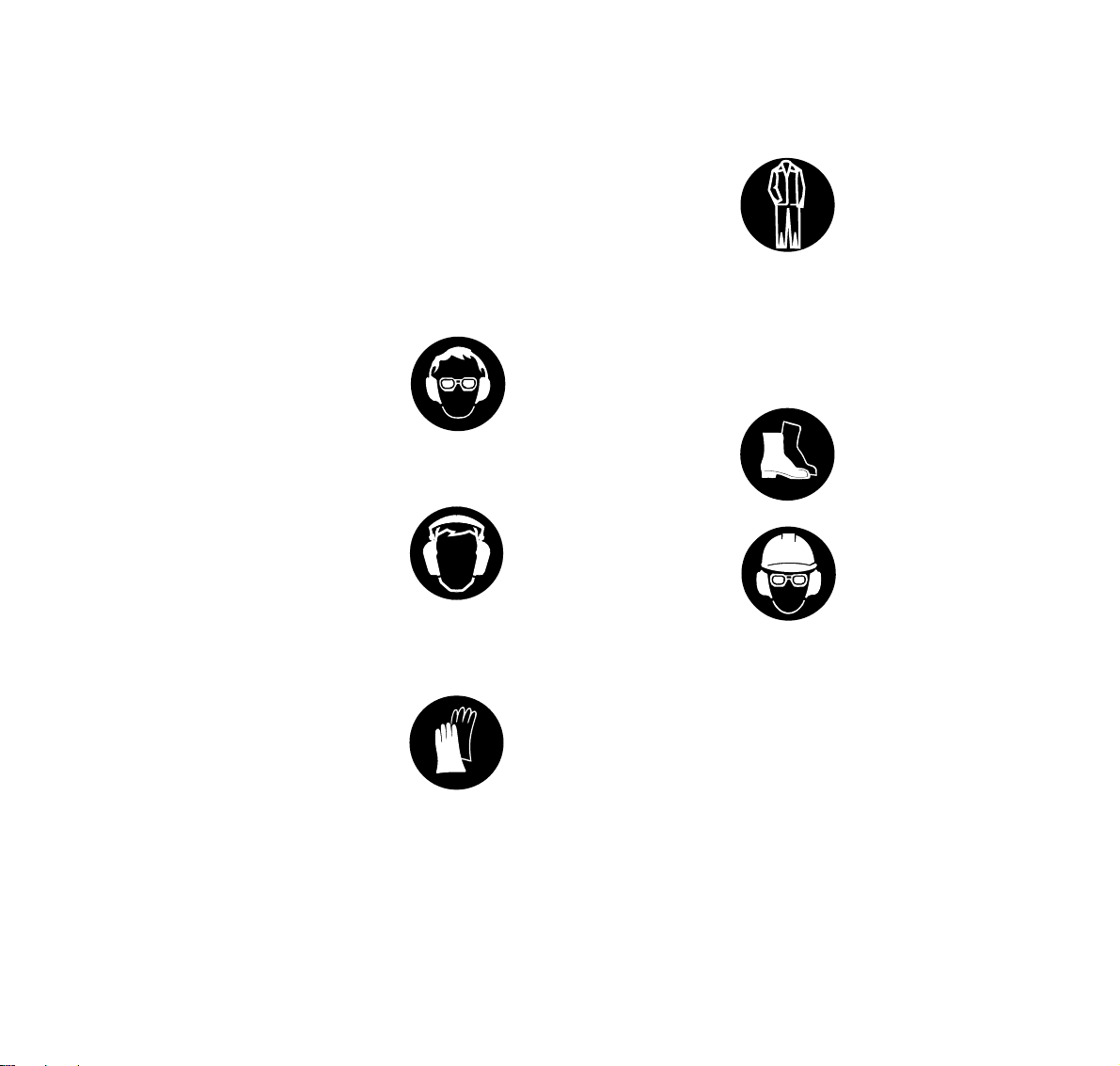
Proper Clothing
!Warning!
To reduce the risk of injury, the operator
should wear proper protective apparel.
Never operate a
PowerSweep unless
wearing goggles or
properly fitted safety
glasses with adequate top
and side protection
complying with your
National Standard.
PowerSweep noise may
damage your hearing.
Wear sound barriers (ear
plugs or ear mufflers) to
protect your hearing.
Continual and regular
users should have their
hearing checked
regularly.
Protect your hands with
gloves when handling the
PowerSweep. Heavyduty, nonslip gloves
improve your grip and
protect your hands.
Clothing must be sturdy
and snug-fitting, but allow
complete freedom of
movement. Avoid loosefitting jackets, scarfs,
neckties, jewelry, flared or
cuffed pants, unconfined longhair or
moving parts of the unit. Wear long
pants made of heavy material to protect
your legs. Do not wear shorts, sandals
or go bare foot. Secure hair so it is above
shoulder level.
Good footing is important
in PowerSweep work.
Wear sturdy boots with
nonslip soles.
Wear an approved safety
hard hat to reduce the risk
of injury to your head
when there is a danger of
head injuries.
!Warning!
The ignition system of the STIHL unit
produces an electromagnetic field of a
very low intensity. This field may
interfere with some pacemakers. To
reduce the risk of serious or fatal injury,
4
KW 85
Page 6

english / USA
THE POWER SWEEP
For illustrations and definitions of the
PowerSweep parts see the chapter on
"Parts and Controls"
!Warning!
Never modify a PowerSweep in any
way. Only attachments supplied by
STIHL or expressly approved by STIHL
for use with the specific STIHL
PowerSweep models are authorized.
Although certain unauthorized
attachments may be useable for the
STIHL Power Sweep, their use may, in
fact, be extremely dangerous.
THE USE OF THE POWER SWEEP
Transporting the PowerSweep
!Warning!
Always turn off the engine and make
sure the attachment has stopped before
putting a PowerSweep down. When
transporting your PowerSweep in a
vehicle, properly secure it to prevent
turnover, fuel spillage and damage to the
PowerSweep.
Preparation for the use of the
PowerSweep
Adjust carrying harness and hand grip to
suit your size before starting work. The
machine should be properly balanced as
specified in your owner's manual for
proper control and less fatique in
operation.
Always check your PowerSweep for
proper condition and operation before
starting, particularly the throttle trigger,
throttle trigger interlock (if applicable),
stop switch, sweeper drums, rubber
sleeve and harness.
The throttle trigger must move freely and
always spring back to the idle position.
The sweeper must be properly tightened
and in safe operating condition. Both
sweeper belts must be mounted. The
rubber sleeve on the end of the drive
tube must be in good condition. Do not
operate your PowerSweep with
damaged sweeper drums or rubber
sleeve. Inspect for loose parts (nuts,
screws, etc) and for worn or damaged
parts. Replace worn or damaged parts.
Fueling
Your STIHL PowerSweep uses an oilgasoline mixture for fuel (see the chapter on "Fuel" of your owner's manual).
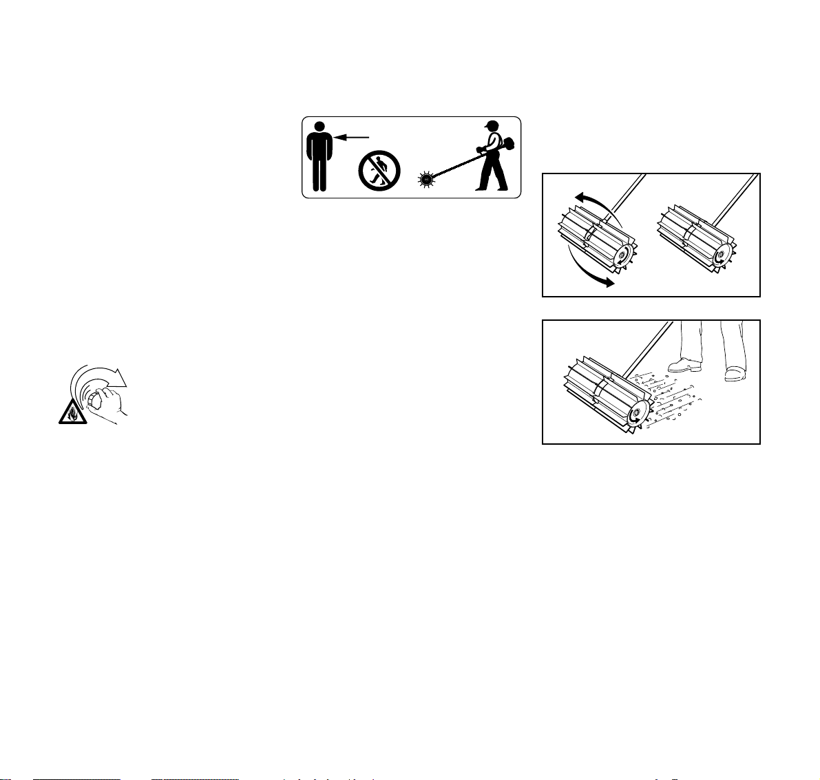
!Warning!
Gasoline is an extremely
flammable fuel. If spilled
and ignited by a spark or
other ignition source, it
can cause fire and serious
burn injury or property
damage. Use extreme caution when
handling gasoline or fuel mix.
Do not smoke or bring any fire or flame
near the fuel.
Fueling Instructions
Fuel your PowerSweep in wellventilated areas, outdoors only.
!Warning!
Gasoline vapor pressure may build up
inside the gas tank of a two cycle engine
depending on the fuel used, the weather
conditions, and the venting system of
the tank. In order to reduce the risk of
burns and other personal injury from
escaping gas vapor and fumes, remove
the fuel filler cap on your PowerSweep
carefully so as to allow any pressure
build-up in the tank to release slowly.
5KW 85
Page 7
english / USA
Never remove fuel filler cap while engine
is running. Select bare ground for fueling
and move at least 10 feet (3 m) from the
fueling spot before starting the engine.
Wipe off any spilled fuel before starting
your PowerSweep and check for
leakage.
!Warning!
Check for fuel leakage while refueling
and during operation. If fuel or oil
leakage is found, do not start or run the
engine until leak is fixed and spilled fuel
has been wiped away. If this happens,
change your clothing immediately.
!Warning!
Unit vibrations can cause
an improperly tightened
fuel cap to loosen or come
off and spill quantities of
fuel. In order to reduce
risk of fuel spillage and
fire, tighten fuel cap by hand with as
much force as possible.
OPERATING INSTRUCTIONS
Starting
!Warning!
Your PowerSweep is a one-person
machine. If you start the engine in the
"start position" the sweeper belts will
rotate when the engine starts - this may
set the PowerSweep in motion back
towards the operator.
5m (16ft)
To reduce the risk of injury from thrown
objects or contact with the sweeper
belts, do not allow any other person
within a radius of 5 m (15 f) of your own
position.
Stop the engine immediately if you are
approached. Start and operate your
PowerSweep without assistance. For
specific starting instructions, see the
appropriate section of your manual.
Place the PowerSweep on firm ground
or other solid surface in an open area.
Maintain a good balance and secure
footing.
!Warning!
When you pull the starter grip, don't
wrap the starter rope around your hand.
Do not allow the grip to snap back, but
guide the starter rope to rewind it
properly. Failure to follow this procedure
may result in injury to hand or fingers
and may damage the starter
mechanism.
With the engine running but at idle,
attach the PowerSweep to the spring
hook of your harness (see appropriate
chapter of this manual).
Working Conditions
Operate and start your PowerSweep
only outdoors in a well ventilated area.
223BA028 KN
223BA029 KN
!Warning!
Reversing the PowerSweep will cause
debris to be thrown back towards the
operator. When reversing the
PowerSweep, use lower throttle settings
and be aware that thrown debris may
also affect your footing.
6
KW 85
Page 8
english / USA
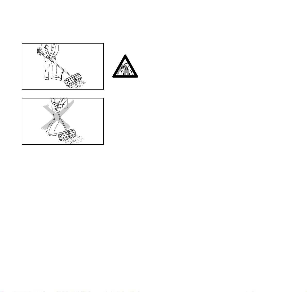
!Warning!
To reduce the risk of injury from loss of
control, maintain a low angle to the work
surface. A high angle of operation tends
to propel the PowerSweep toward you.
!Warning!
Your PowerSweep
produces toxic exhaust
fumes as soon as the
engine is running. These
gases (e.g. carbon
223BA001 KN
colorless and odorless. To reduce the
risk of serious or fatal injury from
inhaling toxic fumes, never run the
PowerSweep indoors or in poorly
ventilated locations.
monoxide) may be
!Warning!
Use of this product can generate dust
and fumes containing chemicals known
to cause respiratory disease, cancer,
223BA002 KN
birth defects, or other reproductive
harm. If you are unfamiliar with the risks
associated with the particular dust or
fume at issue, consult your employer,
governmental agencies such as OSHA
and NIOSH and other sources on
hazardous materials. California and
some other authorities, for instance,
have published lists of substances
known to cause cancer, reproductive
toxicity, etc.
Control dust and fumes at the source
where possible. In this regard use good
work practices and follow the
recommendations of OSHA/NIOSH and
occupational and trade associations.
When the inhalation of toxic dust and
fumes cannot be eliminated, the
operator and any bystanders should
always wear a respirator approved by
NIOSH/MSHA for the type of dust and /
or fumes encountered.
!Warning!
The muffler and other parts of the engine
(e.g. fins of the cylinder, spark plug)
become hot during operation and remain
hot for a while after stopping the engine.
To reduce risk of burns do not touch the
muffler and other parts while they are
hot.
Operate the PowerSweep under good
visibility and daylight conditions only.
Work carefully.
The PowerSweep is designed only for
sweeping sand, stones, gravel, leaves
and snow on grass, concrete or asphalt
and removing puddles of water from flat
surfaces. To reduce the risk of injury, do
not use your PowerSweep for any other
purpose.
7KW 85
Page 9
english / USA
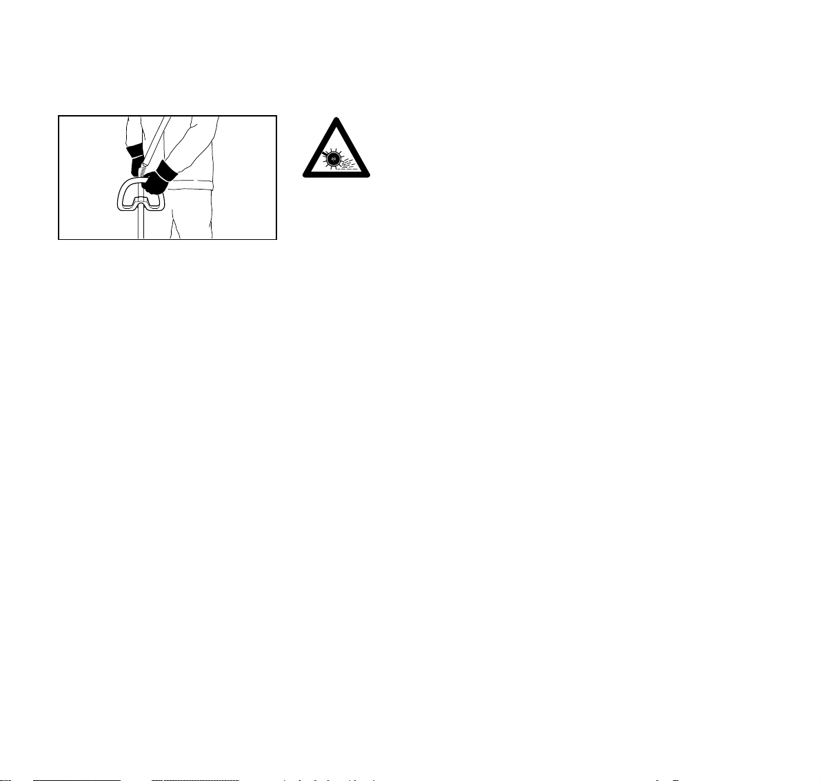
Always hold the PowerSweep firmly with
both hands. Wrap your fingers tightly
around the handles, keeping the
handles cradled between your thumb
and fore-finger. Keep your hands in this
position, to have your PowerSweep
under control at all times. Make sure
your PowerSweep handles and grip are
in good condition and free of moisture,
pitch, oil or grease.
!Warning!
Never attempt to operate any
PowerSweep with one hand. Loss of
control of the PowerSweep may result in
personal injury.
Special care must be taken in slippery
conditions (wet ground, snow).
Examine work area and
check for solid objects
(such as stones, pieces of
metal, etc.) which could
be thrown and cause
injury or damage the
sweeper flaps or other property (e.g.
parked vehicles, windows, etc.).
002BA054 KN
!Warning!
This PowerSweep is to be used at
ground level with the sweeper belts
parallel to the ground. Use of a
PowerSweep above ground level may
increase the risk of injury, since the
brooming attachment is more fully
exposed and the PowerSweep may be
more difficult to control.
Do not operate the PowerSweep using
the starting throttle lock as you do not
have control of the engine speed. See
section of your owner's manual on the
proper use of the slide control.
If the sweeper belts become clogged or
stuck, always turn off the engine and
make sure the sweeper belts have
stopped, before cleaning.
Important adjustments
!Warning!
To reduce the risk of personal injury from
loss of control or contact with the
running sweeper drums, do not use your
PowerSweep with incorrect idle
adjustment. At correct idle speed, the
sweeper drums should not move. For
directions on how to adjust idle speed,
see the appropriate section of your
owner's manual.
If you cannot set the correct idle speed,
have your STIHL dealer check your
PowerSweep and make proper
adjustments and repairs.
MAINTENANCE, REPAIR AND
STORING
Maintenance, replacement, or repair
of the emission control devices and
systems may be performed by any
nonroad engine repair establishment
or individual. However if you claim
warranty for a component which has
not been serviced or maintained
properly or if nonapproved
replacement parts were used, STIHL
may deny warranty.
8
KW 85
Page 10

english / USA
Use only identical STIHL replacement
parts for maintenance and repair. Use of
non-STIHL parts may cause serious or
fatal injury.
Follow the maintenance and repair
instructions in the appropriate section of
your owner's manual. Please refer to the
maintenance chart at the last pages of
this manual.
!Warning!
Always stop the engine and make sure
that the sweeper belts have stopped
before doing any maintenance or repair
work or cleaning the PowerSweep. Do
not attempt any maintenance or repair
work not described in your owner's
manual. Have such work performed at
your STIHL dealer shop only.
!Warning!
Check condition of sweeper belts at
regular intervals. Loose particles or
pieces of the belts could be thrown and
injure the operator or bystanders. To
reduce risk of injury from broken parts
replace damaged sweeper belts
immediately and always in pairs. Do not
reuse or attempt to repair damaged or
worn sweeper belts.
!Warning!
To reduce the risk of fire and burn
injuries, check fuel filler cap for leaks at
regular intervals. Use the specified
spark plug and make sure it and the
ignition lead are always in good
condition.
!Warning!
Never test the ignition system with
ignition wire boot removed from spark
plug or with unseated spark plug, since
uncontained sparking may cause a fire.
!Warning!
To reduce the risk of fire and burn injury,
use only spark plugs authorized by
STIHL. Always press spark plug boot
snugly onto spark plug boot of the
proper size. (Note: If boot has
detachable SAE adapter nut, it must be
attached.) A loose connection between
spark plug boot and ignition wire
connector in the boot may create arcing
that could ignite combustible fumes and
cause a fire. Keep spark plug clean, and
make sure ignition lead is in good
condition.
!Warning!
Do not operate your PowerSweep if the
muffler is damaged, missing or modified.
An improperly maintained muffler will
increase the risk of fire and hearing loss.
Never touch a hot muffler or burn will
result. If your muffler was equipped with
a spark-arresting screen to reduce the
risk of fire (e.g. in the USA, Canada and
Australia), never operate your
PowerSweep if the screen is missing or
damaged. Do not modify or remove any
part of the muffler or spark arresting
screen. Remember that the risk of forest
fires is greater in hot or dry weather.
Tighten all nuts, bolts and screws,
except the carburetor adjustment
screws, after each use.
Additionally, the daily maintenance
schedule for your PowerSweep set forth
in your STIHL Owner's Manual should
be strictly followed.
For any maintenance please refer to the
maintenance chart and to the warranty
statement near the end of this manual.
Store PowerSweep in a dry, high or
locked location out of reach of children.
Before storing for longer than a few
days, always empty the fuel tank.
9KW 85
Page 11
english / USA
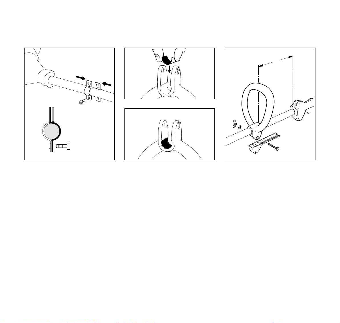
Fitting Carrying Eye* (Clamp)
1
2
2
1
: For position of carrying eye (clamp)*
see “Parts and Controls”
: Place the clamp (1) with tapped
hole against the left-hand side of the
drive tube.
: Place the other half of the clamp (2)
against the right-hand side of the
drive tube.
: Slide the two clamps together so
that their slots engage.
: Insert M 6 x 14 screw (3).
: Line up the carrying eye.
: Tighten down the screw.
3
3
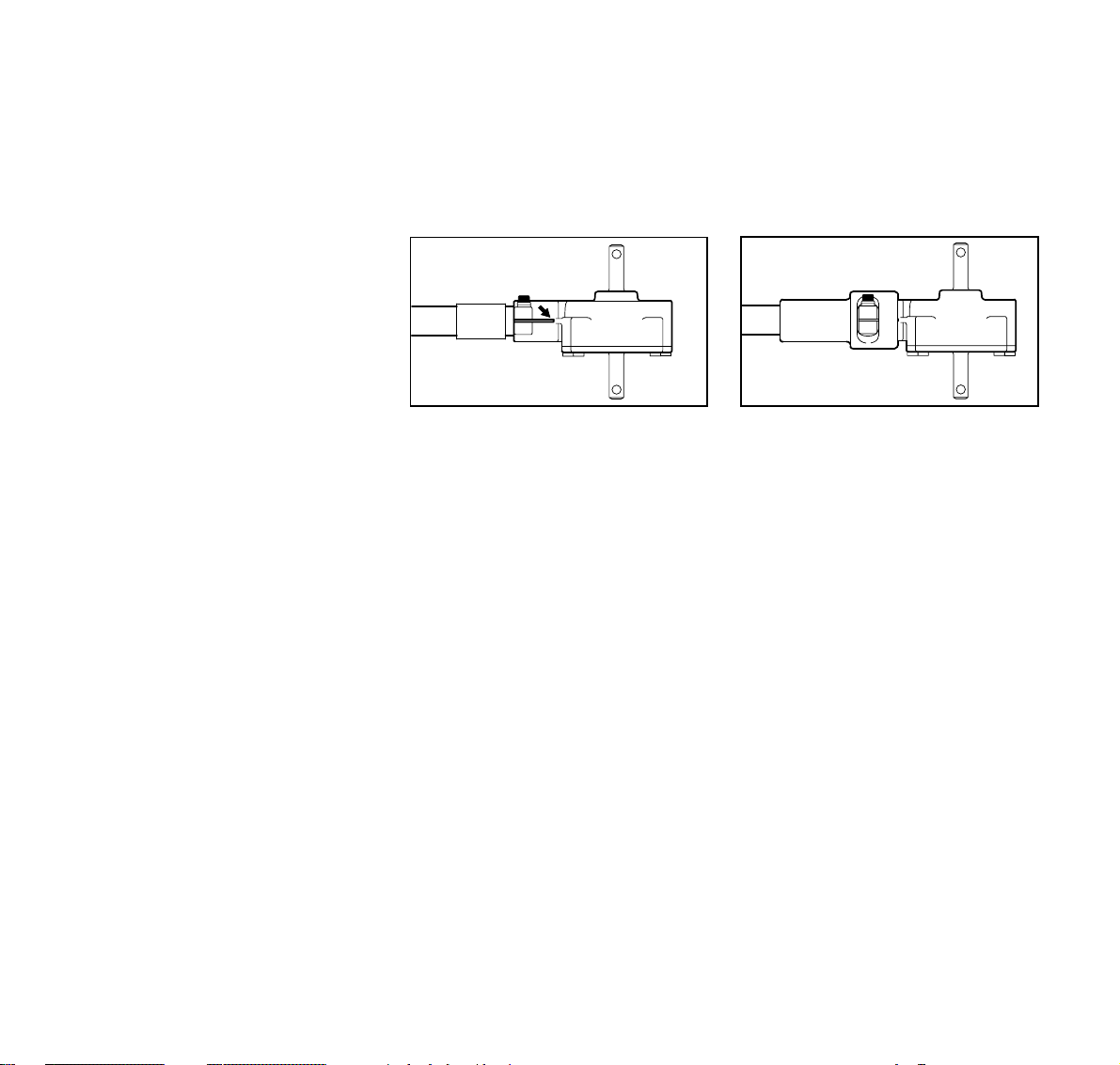
Mounting the Loop Handle
A
1
223BA017 KN
6
5
3
4
002BA115 KN
: Place liner in loop handle as shown. : Fit the loop handle (1) on the drive
223BA018 KN
tube approx. 8 in (20cm) (A) forward
of the control handle (2).
: Slide spacer (3) into loop handle as
far as stop.
: Insert screw (4) in loop handle and
through spacer until the hexagon
head engages the socket in the
loop handle.
: Fit washer (5) and wingnut (6) and
tighten down firmly.
2
232BA027 KN
* see “Guide to Using this Manual”
10
KW 85
Page 12
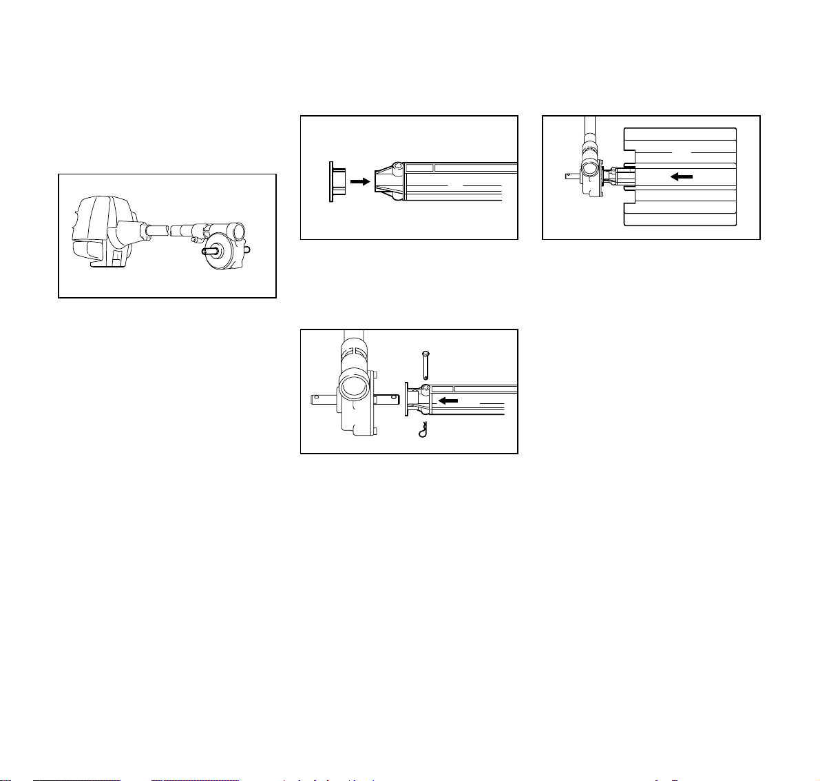
Installing the Gearbox
english / USA
Adjusting loop handle to most
comfortable position:
: Loosen the wingnut (6).
: Turn or move loop handle (1) along
drive tube as required.
: Tighten down wingnut (6) firmly.
Two different versions are supplied at
the present time:
Sleeve on drive tube
1
3
: Release the clamp screw (1).
: Degrease the drive tube in the area
of the clamp.
: Slide the gearbox (2) onto the drive
tube (3) - turn the gearbox back and
forth at the same time until the end
of the tube is no longer visible in the
slot (arrow).
: Push gearbox on as far as stop.
2
Sleeve on gearbox
1
3
223BA005 KN
: Release the clamp screw (1).
: Degrease the drive tube in the area
of the clamp.
: Slide the gearbox with sleeve (2)
onto the drive tube (3) - turn the
gearbox back and forth at the same
time.
: Push gearbox on as far as stop.
2
223BA031 KN
11KW 85
Page 13
english / USA
Mounting Sweeper Drums
Aligning the gearbox
5
5
4
: Line up the gearbox on the drive
tube so that machine support (4)
faces down and the drive shafts (5)
are horizontal.
: Tighten down the clamp screw.
1
: Fit grass shield (1) on end of
226BA006 KN
axle (2) and press home as far as
stop.
4
3
: Push axle (2) onto the output
shaft (3).
: Insert pin (4) through axle and
output shaft. Secure pin with cotter
pin (5).
2
6
2
223BA007 KN
: Push sweeper drum assembly (6)
onto the axle (2) - note the installed
position (see illustration).
223BA009 KN
2
5
223BA008 KN
12
KW 85
Page 14

Fuel
english / USA
7
2
88
: Fit new cotter pin (7) in end of
axle (2) and bend over the ends (8)
of the cotter pin as shown.
: Repeat the procedure on the other
side.
: Always mount both sweeper drum
assemblies.
This engine is certified to operate on
unleaded gasoline and with the mix ratio
50:1.
Your two-stroke engine requires a
mixture of brand-name gasoline and
quality two-stroke engine oil with the
classification TC.
Use regular branded unleaded gasoline
with a minimum octane rating of 89
RON. If the octane rating of the regular
grade gasoline in your area is lower use
premium unleaded fuel.
Fuel with a lower octane rating may
result in preignition (causing "pinging")
which is accompanied by an increase in
engine temperature. This, in turn,
increases the risk of the piston seizure
223BA010 KN
and damage to the engine.
The chemical composition of the fuel is
also important. Some fuel additives not
only detrimentally affect elastomers
(carburetor diaphragms, oil seals, fuel
lines etc.), but magnesium castings as
well. This could cause running problems
or even damage the engine. For this
reason it is essential that you use only
name branded fuels!
Use only STIHL two-stroke engine oil or
equivalent branded two-stroke aircooled engine oils with the classification
TC for mixing.
We recommend STIHL 50:1 two-stroke
engine oil since it is specially formulated
for use in STIHL engines.
Do not use BIA or TCW (two-stroke
water cooled) mix oils!
Take care when handling gasoline.
Avoid direct contact with the skin and
avoid inhaling fuel vapour.
The canister should be kept tightly
closed in order to avoid any moisture
getting into the mixture.
The fuel tank and the canister in which
fuel mix is stored should be cleaned
from time to time.
Fuel mix ages
Only mix sufficient fuel for a few days
work, not to exceed 3 months of storage.
Store in approved safety fuel-canisters
only. When mixing, pour oil into the
canister first, and then add gasoline.
Gasoline
US gal. US fl.oz
12.6
2 1/2 6.4
512.8
Oil (STIHL 50:1 or
equivalent branded TC oils)
Dispose empty mixing-oil canisters only
at authorized disposal locations.
13KW 85
Page 15

english / USA
Fueling
Before fueling, clean the filler cap and
the area around it to ensure that no dirt
falls into the tank.
Always thoroughly shake the mixture in
the canister before fueling your
machine.
In order to reduce the risk of burns
or other personal injury from
escaping gas vapor and fumes,
remove the fuel filler cap carefully
so as to allow any pressure build-up
in the tank to release slowly.
After fueling, tighten fuel cap as
securely as possible by hand.
389BA031 KN
Change the fuel pick up body every
year.
: Before storing your machine for a
long period, drain and clean the fuel
tank and run engine until carburetor
is dry.
Attaching Machine to Harness*
2
2
389BA032 KN
: Attach the spring hook (1) to the
clamp (2).
11
280BA011 KN
14
* see “Guide to Using this Manual”
KW 85
Page 16

Starting
english / USA
3
: Loosen the screw (3).
: Slide the clamp up or down the drive
tube so that the sweeper belts touch
the ground.
: Tighten the screw firmly.
3
223BA012 KN
4
6
5
START
7
223BA013 KN
Controls
Throttle trigger interlock (1), throttle
trigger (2) and slide control (3) with
positions:
START (4),
# - normal run position (5), idle position
and
$ - stop (6),
to stop engine, move slide control in
direction of c (7).
STOP
3
1
2
002BA037 KN
Starting
: Hold down the throttle trigger
interlock and squeeze the throttle
trigger.
: While holding both levers in this
position, move the slide control to
START and hold it there.
: Now release the throttle trigger,
slide control and throttle trigger
interlock in that order. This is the
starting throttle poistion.
15KW 85
Page 17

english / USA
!
! Do not stand or kneel on the drive
! !
8
tube!
: Pull the starter grip slowly with your
right hand until you feel it engage
and then give it a brisk strong pull.
Do not pull out the starter rope all
the way - it might otherwise break.
8
393BA017 KN
: Do not let the starter grip snap back.
Guide it slowly back into the housing
so that the starter rope can rewind
properly.
:::: Continue cranking until engine
runs.
9
Set the choke lever (8):
for cold start to g
for warm start to e -
(even if engine has been running
but is still cold)
: Press fuel pump bulb (9) at least
five times.
16
393BA018 KN
: Hold the unit securely.
: Make sure you have a firm footing.
: Hold the unit with your left hand and
press it down firmly.
!
! If you crank the engine in the
! !
"Start" position, the sweeper
belts may rotate when the engine
starts - this may set the
PowerSweep in motion.
When the engine begins to fire:
: Move the choke lever to e and
355BA007 KN
continue cranking.
KW 85
Page 18

english / USA
As soon as the engine runs:
: Blip the throttle trigger - the
slide control moves to the run
position # and the engine settles down to idle
speed.
Make sure carburetor is correctly
adjusted - the sweeper drums must not
rotate when engine is idling.
Your machine is now ready for
operation.
To shut down the engine:
: Move the slide control in the
direction of c to $ .
At very low outside temperatures:
Allow the engine to warm up.
As soon as engine runs:
: Blip the throttle trigger to disengage
the starting throttle position the slide control moves to the run
position # and the engine returns to
idling speed.
: Open the throttle slightly.
: Allow engine to warm up for a brief
period.
10
If the engine does not start:
If you did not move the choke lever
to e quickly enough after the engine
began to fire, the combustion chamber is
flooded.
: Move choke lever to e
: Set slide control, interlock lever and
throttle trigger to starting throttle
position.
: Crank the engine - pull the starter
rope briskly - 10 to 20 pulls may be
necessary.
If the engine still does not start:
: Move the slide control in direction of
c to $
: Pull off the spark plug boot (10).
: Unscrew and dry off the spark plug.
: Open the throttle wide.
: Crank the engine several times with
the starter to clear the combustion
chamber.
: Refit the spark plug and connect the
spark plug boot - push it down firmly.
: Move slide control to START.
: Set choke lever to e , even if
engine is cold.
: Now start the engine.
393BA019 KN
Fuel tank run until dry and then
refueled
: Press the fuel pump bulb at least
five times - even if bulb is filled with
fuel.
: Now start the engine.
17KW 85
Page 19

english / USA
Operating Instructions Using the PowerSweep
During break-in period
A factory new machine should not be run
at high revs (full throttle off load) for the
first three tank fillings. This avoids
unnecessary high loads during the
break-in period.
As all moving parts have to bed in during
the break-in period, the frictional
resistances in the engine are greater
during this period. The engine develops
its maximum power after about 5 to 15
tank fillings.
During operation
After a long period of full-throttle
operation, allow engine to run for a while
at idle speed so that the heat in the
engine can be dissipated by flow of
cooling air. This protects enginemounted components (ignition,
carburetor) from thermal overload.
After finishing work
Wait for engine to cool down. Drain the
fuel tank . Store the machine in a dry
place. Check tightness of nuts and
screws (not adjusting screws) at regular
intervals and retighten as necessary.
Use the PowerSweep for sweeping
sand, stones, gravel, leaves and snow
on grass, concrete or asphalt and
removing standing water from solid
surfaces.
: To reduce risk of accidents or injury,
remove all obstacles and objects
from the work area.
: If the work area is very dry, spray it
with water if necessary to reduce
the amount of dust created.
: Push the PowerSweep steadily at
walking pace.
: Always keep the drive tube at a
shallow angle (see illustration).
!!!! The steeper the angle between the
drive tube and the ground, the more
difficult it is to control the
PowerSweep.
: Do not push the PowerSweep into
the ground.
Sweeping narrow areas
1
223BA001 KN
: Guide the sweeper drum at right
angles to the direction of travel (1).
Sweepings are thrown forwards, ahead
of the operator.
!!!! The PowerSweep pushes back
toward the operator.
223BA002 KN
223BA026 KN
18
KW 85
Page 20

english / USA
Disconnecting Machine from Harness
Sweeping wide areas
1
: Guide the sweeper drum at an angle
to the direction of travel (1).
Sweepings are thrown forwards to one
side.
!!!! The PowerSweep pushes back
toward the operator.
Sweeping corners
223BA027 KN
: Turn the PowerSweep over.
Sweepings are thrown back toward the
operator. For this reason:
: Run the PowerSweep at a low
throttle setting only.
!!!! The PowerSweep pulls the operator
forward.
!!!! Debris thrown back toward the
operator may affect footing.
2
223BA028 KN
3
: Press down bar (1) on spring
hook (2).
223BA029 KN
: Pull the clamp (3) out of the
spring hook.
1
2
3
223BA014 KN
* see chapter "Special Accessories"
19KW 85
Page 21

english / USA
Cleaning the Air Filter
2
3
355BA031 KN
Dirty air filters reduce engine power
increase fuel consumption and make
starting more difficult.
If there is a noticeable loss of engine
power
: Move choke lever to g
: Press in the tab (1).
: Ease the filter cover (2) over the tab
and take it away.
: Clean away loose dirt from around
the filter.
: Remove the foam and felt filter
elements.
4
355BA014
: Wash the foam element in a clean,
non-flammable cleaning solution
(e.g. warm soapy water) and then
dry.
: Fit new felt element.
As a temporary measure you can
knock it out on the palm of your
hand or blow it out with compressed
air. Do not wash.
Replace damaged parts.
: Install the foam element (3) in the
filter cover (2).
: Place felt element (4) (lettering
facing inward) in filter housing (5).
: Fit filter cover so that it snaps into
position.
5
355BA032 KN
20
KW 85
Page 22

Motor Management Adjusting the Carburetor
with idle speed screw (LD)
english / USA
Exhaust emissions are controlled by the
design of the fundamental engine
parameters and components (e.g.
carburation, ignition, timing and valve or
port timing) without the addition of any
major hardware.
LD
The carburetor is set at the factory to
provide an optimum fuel-air mixture
under all operating conditions.
Standard setting
: Mount the sweeper drum
assemblies.
: Check spark arresting screen* and
clean or replace as necessary.
: Check the air filter and replace as
necessary.
: Carefully screw the idle speed
screw (LD) down onto its seat
counterclockwise (left-hand thread).
Then open it two full turns
clockwise (standard setting).
392BA000 KN
* see chapter "Key to Symbols"
* see chapter "Key to Symbols"
21KW 85
Page 23

english / USA
Adjusting the Carburetor
with Idle Speed Screw LA
Adjusting idle speed
: Carry out standard setting.
: Start the engine and allow it to warm
up.
Engine stops while idling:
: Turn the idle speed screw (LD)
slowly clockwise until the engine
runs smoothly - the sweeper drums
must not rotate.
Sweeper drums rotate when engine
is idling:
: Turn the idle speed screw (LD)
counterclockwise until the sweeper
drums stop rotating - then turn the
screw about another full turn in the
same direction from that position.
Erratic idling behavior,
poor acceleration:
: Turn the idle speed screw (LD)
slowly counterclockwise no more
than one half turn.
HL
3 / 4
1
LA
The carburetor comes from the factory
with a standard setting.
This setting provides an optimum fuel-air
mixture under most operating
conditions.
With this carburetor it is only possible to
adjust the engine idle speed within fine
limits.
Standard Setting
: Mount the sweeper drum assembly
and make sure it is in good
condition.
: Check spark arresting screen* and
clean or replace as necessary.
: Check the air filter and replace if
necessary.
: Turn high speed screw (H)
counterclockwise (max.
far as stop.
: Carefully screw the low speed
screw (L) down onto its seat. Then
open it one turn counterclockwise.
: Start the engine and allow it to warm
265BA024 KN
up as necessary.
: Adjust idle speed with the idle speed
screw (LA) so that the sweeper
drum does not rotate.
Fine Tuning
A slight correction of the high speed
screw (H) may be necessary if engine
power is unsatisfactory when working at
high altitudes or at sea level.
3
/4 turn) as
22
* see “Guide to Using this Manual”
KW 85
Page 24

english / USA
: Carry out the standard setting.
: Run the PowerSweep for about 3 to
5 minutes to warm up the engine.
Rule of thumb
Turn the high speed screw (H) about 1 to
2 notches for every 1000 meter change
in altitude,
: Open the throttle wide.
At high altitudes
: Turn the high speed screw (H)
clockwise (leaner) no further than
stop until there is no noticeable
increase in engine speed.
At sea level
: Turn the high speed screw (H)
counterclockwise (richer) no further
than stop until there is no noticeable
increase in engine speed.
It is possible that maximum engine
speed may be reached with the
standard setting in each case.
Adjusting Idle Speed
It is usually necessary to change the
setting of the idle speed screw (LA)
after every correction to the low speed
screw (L).
: Warm up engine.
Engine stops while idling
: Turn idle speed screw (LA) slowly
clockwise until the engine runs
smoothly – sweeper drum must not
rotate.
Sweeper drum rotates when engine is
idling
: Turn idle speed screw (LA) slowly
counterclockwise until sweeper
drum stops rotating and then turn
the screw about another
1
/2 to 1 turn
in the same direction.
Erratic idling behavior, engine stops
even though setting of LA screw is
correct, poor acceleration
Idle setting too lean:
: Turn low speed screw (L)
counterclockwise (about 1/4 turn)
until the engine runs and
accelerates smoothly.
Erratic idling behavior
Idle setting too rich:
: Turn low speed screw (L) clockwise
(about
1
/4 turn) until the engine runs
and accelerates smoothly.
23KW 85
Page 25

english / USA
Checking the Spark Plug
Wrong fuel mix (too much engine oil in
the gasoline), a dirty air filter and
unfavorable running conditions (mostly
at part throttle etc.) affect the condition of
the spark plug. These factors cause
deposits to form on the insulator nose
which may result in trouble in operation.
If engine is down on power, difficult
to start or runs poorly at idling speed,
first check the spark plug.
: Remove spark plug as discribed
in chapter “Starting“
: Clean dirty spark plug.
: Check electrode gap (A) -
it should be 0.5mm/0.02" readjust if necessary.
: Use only resistor type spark plugs
of the approved range.
Rectify problems which have caused
fouling of spark plug:
: Too much oil in fuel mix.
000BA002 KN
: Dirty air filter.
: Unfavorable running conditions.
Fit a new spark plug after approx. 100
operating hours
or earlier if the electrodes are badly
eroded.
1
000BA036 TR
To reduce the risk of fire and burn
injury, use only spark plugs
authorized by STIHL. Always press
spark plug boot (2) snugly onto
spark plug boot (1) of the proper
size. (Note: If boot has detachable
SAE adapter nut, it must be
attached.) A loose connection
between spark plug boot and
ignition wire connector in the boot
may create arcing that could ignite
combustible fumes and cause a fire.
24
KW 85
Page 26

english / USA
Removing the Gearbox
: Straighten the ends of the cotter pin,
remove the cotter pin.
: Pull the sweeper drum off the shaft.
: Examine gear housing for signs of
oil. If leaks are found, have your
STIHL dealer check the gearbox.
: Repeat the above procedure on the
other side.
1
3
2
Replacing the Rubber Sleeve
The rubber sleeve protects the drive
tube from wear caused by contact with
the sweeper belts. It is fitted on either the
drive tube or the gearbox.
A worn sleeve must be replaced as
follows:
: Remove the gearbox -
223BA022 KN
223BA015 KN
see "Removing the Gearbox".
Sleeve on drive tube
: Remove the worn sleeve from the
drive tube. Cut it open with a knife if
necessary.
Sleeve on gearbox
223BA032 KN
: Pull the worn sleeve off the gearbox.
223BA025 KN
223BA033 KN
: Push new sleeve onto the gearbox.
: Install the gearbox - see "Installing
the Gearbox".
: Release the clamp screw (1).
: Pull the gearbox (2) off the drive
tube (3) - turn the gearbox back and
forth at the same time to ease
removal.
25KW 85
Page 27

english / USA
Replacing Sweeper Drum
: Straighten the ends of the cotter pin,
remove the cotter pin.
: Pull the sweeper drum off the axle.
: Repeat the procedure on the other
side.
: Examine gear housing for signs of
oil. If leaks are found, have your
STIHL dealer check the gearbox.
2
6
7
2
223BA022 KN
88
: Fit new cotter pin (7) in end of
axle (2) and bend over the ends (8)
of the cotter pin as shown.
: Repeat the procedure on the other
side.
: Always replace sweeper drum
assemblies in pairs.
223BA009 KN
Replacing the Starter Rope and Rewind Spring
1
2
1
3
223BA010 KN
: Take out the screws (1).
: Remove the cable lug.
: Lift the starter cover (2) away from
the tank (3) and pull it out from
under the shroud (4).
4
1
386BA004 KN
: Push new sweeper drum (6) onto
the axle (2).
26
KW 85
Page 28

english / USA
6
392BA024 KN
5
: Take out the screw (5).
: Remove the rope rotor very
carefully –
the rewind spring is seated in the
rope rotor and may pop out and
uncoil if care is not taken.
7
392BA014 KN
: Use a screwdriver to ease the cap
(6) out of the starter grip.
: Remove remaining rope from the
rotor and grip, making sure the
ElastoStart sleeve is not pushed out
of the grip.
: Tie a simple overhand knot in the
end of the new starter rope and then
thread the rope through the top of
the grip and the rope bush (7).
: Refit the cap in the grip.
8
392BA015 KN
: Pull the rope through the rotor and
secure it with a simple overhand
knot.
: Coat rope rotor bearing bore with
non-resinous oil**.
: Slide rotor onto starter post –
turn it back and forth until the rewind
spring anchor loop (8) engages.
: Insert screw and tighten down
securely.
Go to "Tensioning the rewind
spring".
392BA025 KN
** see “Special Accessories“
27KW 85
Page 29

english / USA
Replacing a broken rewind spring
: Lubricate the new spring with a few
drops of non-resinous oil**, do not
open the wire retainer
: Remove the rope rotor.
: Remove parts of old spring.
: Fit the new spring –
position outer spring loop in the
recess –
the wire retainer slips off in this
process.
a = 2mm
(0.08in)
355BA022 KN
355BA021 KN
** see “Special Accessories“
28
If the spring has popped out:
Refit it in the counterclockwise
direction –
starting outside and working inward.
: Install the rope rotor.
: Check dimension "a" on inner
spring loop and bend it to size if
necessary.
: Go to "Tensioning the rewind
spring".
Tensioning the rewind spring
: Make a loop in the unwound
starter rope and use it to turn
the rope rotor six full revolutions
counterclockwise.
Hold the rotor steady –
straighten the twisted rope –
release the rotor –
let go of rope slowly so that it winds
onto the rotor.
KW 85
Page 30

The starter grip must be firmly seated in
the rope guide bush.
If grip droops to one side:
Add one more turn on rope rotor to
increase spring tension.
: When the starter rope is fully
extended it must be possible to
rotate the rotor another half turn.
If this is not the case, the spring is
overtensioned and could break.
Take one turn of rope off the rotor.
english / USA
Spark Arresting Screen in Muffler
: Fit the starter cover.
To do this, push the upper mounting
boss under the shroud –
line up the tank and push lower part
of cover onto the tank.
: Insert and tighten down the housing
screws.
Secure cable lug in position.
386BA005 KN
If the engine is low on power, check the
spark arresting screen* in the muffler.
: Lift spark arresting screen and pull it
out sideways.
: Clean spark arresting screen if
necessary.
: If screen is damaged or coked up, fit
a new one.
: Refit the spark arresting screen.
* see “Guide to Using this Manual”
392BA035 KN
29KW 85
Page 31

english / USA
Engine Running Behavior Storing the Machine
If engine running behavior is
unsatisfactory even though the air filter
is clean and the carburetor properly
adjusted, the cause may be in the
muffler.
Have the muffler checked for
contamination (coking) by a STIHL
dealer.
For periods of about 3 months or
longer
: Drain and clean the fuel tank in a
well ventilated area.
: Run engine until carburetor is dry -
this helps prevent carburetor
diaphragms sticking together.
: Remove and clean the sweeper
drums, inspect belts for damage or
wear.
: Thoroughly clean the machine - pay
special attention to the cylinder fins
and air filter.
: Store the machine in a dry, high or
locked location - out of the reach of
children and other unauthorized
persons.
30
KW 85
Page 32

Maintenance Chart
The following maintenance intervals apply to normal operating conditions.
If your daily working time is longer than normal or operating conditions are difficult (very
dusty work area, etc.), shorten the specified intervals accordingly.
Visual inspection (condition,
Complete machine
Control handle Check operation
Air filter
Filter in fuel tank
Fuel tank Clean
Carburetor
Spark plug Readjust electrode gap
Colling air intakes
Spark arresting screen in muffler
All accessible screws and nuts (not adjusting screws) Retighten
Rubber buffers Have replaced by STIHL dealer
Sweeper drum assemblies
Drive shaft
Sleeve (drive tube protector)
leaks)
Clean
Clean
Replace
Check
Replace
Check idle adjustment sweeper belts must not rotate
Readjust idle
Inspect
Clean
Inspect
Clean or replace
Check
Replace
Check
Lubricate
Check
Replace
english / USA
before
starting work
after finishing
work or daily
after each
refueling stop
weekly
monthly
if problem
if damaged
XX
X
XX
XX
X
X
XX
XX
XX
X
X
XX
XX
X
XXX
XX
XX
XXX
X
as required
X
X
X
X
31KW 85
Page 33

english / USA
32
KW 85
Page 34

Parts and Controls
1
3
english / USA
1 Loop handle
2 Spacer
3 Clamp (carrying ring)
7
4
5
8
4 Slide control
5 Throttle trigger interlock
6 Throttle trigger
7 Spark plug boot
8 Air filter cover
9 Machine support
14
11
15
13
2
12
10
6
9
223BA019 KN
10 Fuel tank
11 Fuel filler cap
12 Starter grip
13 Fuel pump (primer bulb)
14 Choke lever
15 Carburetor adjusting screw
16 Muffler (with spark arresting screen
in some markets)
17 Shaft
18 Sleeve (shaft protector)
19 Sweeper drum assembly
20 Axle
21 Gearbox
223BA021 KN
16
17
18
19
20
21
223BA020 KN
33KW 85
Page 35

english / USA
Definitions
1. Loop handle.
For control of machine.
2. Spacer.
Maintains minimum distance
between left and right hands during
operation.
3. Clamp (carrying ring).
The device to connect the power
sweep to the harness.
4. Slide control / Stop switch.
Starting throttle lock, run and stop
switch. Keeps the throttle partially
open during starting. The stop
switch switches the engine's ignition
off and stops the running engine.
5. Throttle trigger interlock.
Must be depressed before the
throttle trigger can be activated.
6. Throttle trigger.
Controls the speed of the engine.
7. Spark plug boot.
Connects the spark plug to the
ignition wire.
8. Air filter cover.
Covers the air filter element.
9. Machine support.
For resting machine on the ground.
10. Fuel tank.
For fuel and oil mixture.
11. Fuel filler cap.
For closing the fuel tank.
12. Starter grip.
The grip of the pull starter, which is
the device to start the engine.
13. Fuel pump (primer bulb).
Provides manual fuel feed for a cold
start.
14. Choke lever.
Eases cold engine starting by
enriching mixture.
15. Carburetor adjusting screw.
For tuning carburetor.
16. Muffler
(with spark arresting screen).
Attenuates exhaust noises and
diverts exhaust gases away from
operator.
The spark arresting screen is
designed to reduce the risk of fire.
17. Shaft.
Device to connect the engine with
the gearbox.
18. Sleeve (shaft protector).
Designed to protect the shaft
against abrasion from the sweeper
flaps.
19. Sweeper drum assembly.
Tool for sweeping and cleaning.
20. Axle.
Connects sweeper drum assembly
with the drive shaft.
21. Gearbox.
To transform the engine speed
down to lower RPM of the sweeper
drums.
34
KW 85
Page 36

Specifications
english / USA
Engine Ignition System
Single cylinder two-stroke engine
Displacement: 1.55cu.in (25.4cc)
Bore: 1.34in (34mm)
Stroke: 1.10in (28mm)
Engine power to
ISO 8893: 0.95kW (1.3bhp)
Idle speed: 2800rpm
Max. drum
speed: approx. 200rpm
Type: Electronic
Spark plug
(suppressed): Bosch WSR 6 F,
Electrode gap: 0.02in (0.5mm)
Spark plug thread: M 14 x 1.25;
magneto ignition
NGK BPMR 7 A
or Champion
RCJ 6Y *
0.37in (9.5mm)
long
Fuel System
Carburetor: All position
diaphragm
carburetor with
integral fuel
pump
Air filter: Foam and felt
elements
Fuel tank capacity: 15fl.oz (0.44 l)
Fuel mix: see "Fuel"
Weight
without drum
assemblies 19.6lbs (8.9kg)
Sweeper Drum
Quantity 2
Width 22.4in (57cm)
No. of rubber
paddles 12
* see chapter "Key to Symbols"
35KW 85
Page 37

english / USA
Special Accessories Maintenance and Repairs
STIHL gear lubricant for hedge
trimmers
2.8oz (80g) tube 0781 120 1109
8oz (225g) tube 0781 120 1110
The user of this unit should carry out
only the maintenance operations
described in this manual. Other repair
work may be performed only by an
authorized STIHL dealer.
Warranty claims following repairs can be
accepted only if the repair has been
performed by an authorized STIHL
dealer using original STIHL replacement
parts.
Original STlHL parts can be identified by
the STIHL part number, the
STIHl
STIHlSTIHl
STIHl
logo and the STlHL parts symbol ((((.
The symbol may appear alone on small
parts.
36
KW 85
Page 38

STIHL Incorporated Federal and California Emission Control Warranty Statement
english / USA
Your Warranty Rights
and Obligations
The U.S. Environmental Protection
Agency (EPA), the California Air
Resources Board (CARB) and STIHL
Incorporated are pleased to explain the
Emission Control System Warranty on
your model year 2000 and later
equipment type engine. In California,
new small off-road engines must be
designed, built and equipped to meet the
State's stringent anti-smog standards. In
other states, new 1997 and later model
year small off-road equipment engines
must be designed, built and equipped, at
the time of sale, to meet the U.S. EPA
regulations for small non road engines.
The equipment engine must be free from
defects in materials and workmanship
which cause it to fail to conform with
U.S. EPA standards for the first two
years of engine use from the date of sale
to the ultimate purchaser.
STIHL Incorporated must warrant the
emission control system on your small
off-road engine for the period of time
listed below provided there has been no
abuse, neglect or improper maintenance
of your small off-road equipment engine.
Your emission control system includes
parts such as the carburetor and the
ignition system. Also included may be
hoses, and connectors and other
emission related assemblies.
Where a warrantable condition exists,
STIHL Incorporated will repair your
small off-road equipment engine at no
cost to you, including diagnosis (if the
diagnostic work is performed at an
authorized dealer), parts, and labor.
Manufacturer's Warranty
Coverage:
The small off-road equipment engines
are warranted for two years in California.
In other states, 1997 and later model
year small off-road equipment engines
are also warranted for two years. If any
emission-related part on your engine is
defective, the part will be repaired or
replaced by STIHL Incorporated free of
charge.
Owner's Warranty
Responsibilities:
As the small off-road equipment engine
owner, you are responsible for the performance of the required maintenance
listed in your owner's manual. STIHL
Incorporated recommends that you
retain all receipts covering maintenance
on your small off-road equipment
engine, but STIHL Incorporated cannot
deny warranty solely for the lack of
receipts or for your failure to ensure the
performance of all scheduled
maintenance.
Any replacement part or service that is
equivalent in performance and durability
may be used in non-warranty maintenance or repairs, and shall not reduce the
warranty obligations of the engine
manufacturer.
As the small off-road equipment engine
owner, you should be aware, however,
that STIHL Incorporated may deny you
warranty coverage if your small off-road
equipment engine or a part has failed
due to abuse, neglect, improper
maintenance or unapproved
modifications.
You are responsible for presenting your
small off-road equipment engine to a
STIHL service center as soon as a
problem exists. The warranty repairs will
be completed in a reasonable amount of
time, not to exceed 30 days.
If you have any questions regarding your
warranty rights and responsibilities,
please contact a STIHL customer
service representative at
1-800-467-8445 or you can write to
STIHL Inc., 536 Viking Drive,
P.O. Box 2015,
Virginia Beach, VA 23450-2015.
Coverage by STIHL Incorporated
STIHL Incorporated warrants to the
ultimate purchaser and each
subsequent purchaser that your small
off-road equipment engine will be
designed, built and equipped, at the time
of sale, to meet all applicable
regulations. STIHL Incorporated also
warrants to the initial purchaser and
each subsequent purchaser that your
engine is free from defects in materials
and workmanship which cause the
engine to fail to conform with applicable
regulations for a period of two years.
37KW 85
Page 39

english / USA
Warranty Period
The warranty periods will begin on the
date the utility equipment engine is
purchased by the initial purchaser and
you have signed and sent back the
warranty card to STIHL. If any emission
related part on your engine is defective,
the part will be replaced by STIHL
Incorporated at no cost to the owner.
Any warranted part which is not
scheduled for replacement as required
maintenance, or which is scheduled only
for regular inspection to the effect of
"repair or replace as necessary" will be
warranted for the warranty period.
Any warranted part which is scheduled
for replacement as required maintenance will be warranted for the period of
time up to the first scheduled replacement point for that part.
Diagnosis
You, as the owner, shall not be charged
for diagnostic labor which leads to the
determination that a warranted part is
defective. However, if you claim
warranty for a component and the
machine is tested as non-defective,
STIHL Incorporated will charge you for
the cost of the emission test.
Mechanical diagnostic work will be
performed at an authorized STIHL
servicing dealer. Emission test may be
performed either at STIHL Incorporated
or at any independent test laboratory.
Warranty Work
STIHL Incorporated shall remedy warranty defects at any authorized STIHL
servicing dealer or warranty station. Any
such work shall be free of charge to the
owner if it is determined that a warranted
part is defective. Any manufacturerapproved or equivalent replacement part
may be used for any warranty
maintenance or repairs on emissionrelated parts and must be provided
without charge to the owner. STIHL
Incorporated is liable for damages to
other engine components caused by the
failure of a warranted part still under
warranty.
The California Air Resources Board's
Emission Warranty Parts List specifically
defines the emission-related warranted
parts. These warranted parts are:
Carburetor
Choke (Cold start enrichment system)
Intake manifold
Air filter
Spark plug
Magneto or electronic ignition system
(ignition module)
Catalytic converter (if applicable)
Fasteners
Where to make a claim for
Warranty Service
Bring the product to any authorized
STIHL servicing dealer and present the
signed warranty card.
Maintenance Requirements
The maintenance instructions in this
manual are based on the application of
the recommended 2-stroke fuel-oil
mixture (see also instruction "Fuel").
Deviations from this recommendation
regarding quality and mixing ratio of fuel
and oil may require shorter maintenance
intervals.
Limitations
This Emission Control Systems Warranty shall not cover any of the following:
: repair or replacement required
because of misuse, neglect or lack
of required maintenance,
: repairs improperly performed or
replacements not conforming to
STIHL Incorporated specifications
that adversely affect performance
and/or durability, and alterations or
modifications not recommended or
approved in writing by STIHL
Incorporated,
and
: replacement of parts and other
services and adjustments
necessary for required maintenance
at and after the first scheduled
replacement point.
38
KW 85
Page 40

Quality Certification
All STIHL products comply with the
highest quality standards.
An independent organization has
certified that all products manufactured
by STIHL meet the strict requirements of
the ISO 9001 standard for quality
management systems in terms of
product development, materials
purchasing, production, assembly,
documentation and customer service.
english / USA
000BA026
39KW 85
Page 41

&. WARNING!
The engine exhaust from this product'
contains chemicals known to the State
of Californiato cause
defects or other reproductive harm.
0458 223 3021
englisch I english USA I CARB I EPA
Q<:;1ncer, birth
 Loading...