

Page 1
STIHL KMA 130 R
Gebrauchsanleitung
Instruction Manual
Notice d’emploi
Istruzioni d’uso
Handleiding
Page 2

D Gebrauchsanleitung
1 - 26
G Instruction Manual
27 - 50
F Notice d’emploi
51 - 77
I Istruzioni d’uso
78 - 101
n Handleiding
102 - 127
Page 3

Inhaltsverzeichnis
deutsch
1 Vorwort
. . . . . . . . . . . . . . . . . . . . . . . . . . . . . . . . . . . . . . . . . . . . .
2 Informationen zu dieser Gebrauchsanleitung
2.1 Geltende Dokumente
. . . . . . . . . . . . . . . . . . . . . . . . . . . . . . . .
2.2 Kennzeichnung der Warnhinweise im Text
2.3 Symbole im Text
3 Übersicht
3.1 KombiMotor
3.2 Tragsysteme
3.3 Symbole
Original-GebrauchsanleitungGedruckt auf chlorfrei gebleichtem Papier.
4 Sicherheitshinweise
4.1 Warnsymbole
. . . . . . . . . . . . . . . . . . . . . . . . . . . . . . . . . . . . . . . . . . . .
. . . . . . . . . . . . . . . . . . . . . . . . . . . . . . . . . . . . . . . . . . . .
. . . . . . . . . . . . . . . . . . . . . . . . . . . . . . . . . . . .
. . . . . . . . . . . . . . . . . . . . . . . . . . . . . . . . . . . . . . . . .
. . . . . . . . . . . . . . . . . . . . . . . . . . . . . . . . . . . . . . . .
. . . . . . . . . . . . . . . . . . . . . . . . . . . . . . . . .
. . . . . . . . . . . . . . . . . . . . . . . . . . . . . . . . . . . . . . .
4.2 Bestimmungsgemäße Verwendung
4.3 Anforderungen an den Benutzer
4.4 Bekleidung und Ausstattung
4.5 Arbeitsbereich und Umgebung
4.6 Sicherheitsgerechter Zustand
4.7 Arbeiten
4.8 Transportieren
4.9 Aufbewahren
. . . . . . . . . . . . . . . . . . . . . . . . . . . . . . . . . . . . . . . . . . . . .
. . . . . . . . . . . . . . . . . . . . . . . . . . . . . . . . . . . . . .
. . . . . . . . . . . . . . . . . . . . . . . . . . . . . . . . . . . . . . . .
. . . . . . . . . . . . . . . . . . . . . . . . .
. . . . . . . . . . . . . . . . . . . . . .
. . . . . . . . . . . . . . . . . . . . . . .
4.10 Reinigen, Warten und Reparieren
5 KombiMotor einsatzbereit machen
5.1 KombiMotor einsatzbereit machen
6 KombiMotor zusammenbauen
Druckfarben enthalten pflanzliche Öle, Papier ist recycelbar.
6.1 Rundumgriff anbauen
. . . . . . . . . . . . . . . . . . . . . . . . . . . . . .
. . . . . . . . . . . . . . . . . . . . . .
6.2 Rundumgriff mit Schrittbegrenzer anbauen
7 KombiMotor für den Benutzer einstellen
7.1 Verwendung mit Akku STIHL AR
7.2 Verwendung mit Tragsystem
. . . . . . . . . . . . . . . . . . . . . . .
7.3 Verwendung mit „Gürteltasche AP mit
Anschlussleitung“
. . . . . . . . . . . . . . . . . . . . . . . . . . . . . . . . . .
7.4 Rundumgriff ausrichten und einstellen
8 Stecker der Anschlussleitung einstecken und
ausstecken
. . . . . . . . . . . . . . . . . . . . . . . . . . . . . . . . . . . . . . . . .
. . . . . . . .
. . . . . . . . . . .
. . . . . . . . . . . . . . . . . .
. . . . . . . . . . . . . . . . . . . . .
. . . . . . . . . . . . . . . . . . .
. . . . . . . . . . . . . . . . . . .
. . . . . . . . . . . . . . . . . . .
. . . . . . . . .
. . . . . . . . . . . .
. . . . . . . . . . . . . . . . . . .
. . . . . . . . . . . . . .
8.1 Stecker der Anschlussleitung einstecken
2
8.2 Stecker der Anschlussleitung herausziehen
2
9 KombiMotor einschalten und ausschalten
2
9.1 KombiMotor einschalten
3
9.2 KombiMotor ausschalten
3
10 KombiMotor prüfen
3
10.1 Bedienungselemente prüfen
3
11 Mit dem KombiMotor arbeiten
4
11.1 KombiMotor halten und führen
5
11.2 Leistungsstufe einstellen
5
11.3 Arbeiten
5
12 Nach dem Arbeiten
5
12.1 Nach dem Arbeiten
6
6
13 Transportieren
6
13.1 KombiMotor transportieren
7
14 Aufbewahren
7
14.1 KombiMotor aufbewahren
8
15 Reinigen
8
15.1 KombiMotor reinigen
8
16 Warten und Reparieren
9
16.1 KombiMotor warten und reparieren
9
17 Störungen beheben
10
17.1 Störungen des KombiMotors und des Akkus
10
10
10
10
12
beheben
18 Technische Daten
18.1 KombiMotor STIHL KMA 130 R
18.2 Schallwerte und Vibrationswerte
18.3 REACH
13
19 Kombinationen mit KombiWerkzeugen
14
19.1 STIHL KMA 130 R
. . . . . . . . . . . . . . . . . . . . . . . . . . . . . . . . . . . . . . . . . . .
. . . . . . . . . . . . . . . . . . . . . . . . . . . . . . . . . . . . .
. . . . . . . . . . . . . . . . . . . . . . . . . . . . . . . . . . . . . . .
. . . . . . . . . . . . . . . . . . . . . . . . . . . . . . . . . . . . . . . . . . .
. . . . . . . . . . . . . . . . . . . . . . . . . . . . . . . . . . . . . . . . . . .
. . . . . . . . . . . . . . . . . . . . . . . . . . . . . . . . . . . . . . . . . . . .
20 Ersatzteile und Zubehör
15
20.1 Ersatzteile und Zubehör
. . . . . . . . . . . . . . . . . . . . . . . . . . . .
. . . . . . . . . . . . . . . . . . . . . . . . . . .
. . . . . . . . . . . . . . . . . . . . . . . . . . . . . . . . .
. . . . . . . . . . . . . . . . . . . . . . .
. . . . . . . . . . . . . . . . . . . . . . . . . . .
. . . . . . . . . . . . . . . . . . . . . . . . . . . . . . . . .
. . . . . . . . . . . . . . . . . . . . . . . . . . . . . . . .
. . . . . . . . . . . . . . . . . . . . . . . . .
. . . . . . . . . . . . . . . . . . . . . . . . . .
. . . . . . . . . . . . . . . . . . . . . . . . . . . . . . .
. . . . . . . . . . . . . . . . . . . . . . . . . . . .
. . . . . . . . . . . . . . . . . . . . . . . . . . . . . . . .
. . . . . . . . . . . . . . . . . . . . . . . . . . . . . . . . . .
. . . . . . . . . . . . . . . . . . . . . . . . . . . . . . . . .
. . . . . . . . . . . . . . . . . . . . . . . . . . . .
. . . . . . . . . . . . . . . . . . . . . . . . . . . .
. . . . . . . . . . .
. . . . . . . .
. . . . . . . . . .
. . . . . . . . . . . . . . . . . . . . . .
. . . . . . . . . . . . . . . . . . . . .
. . . . . . . . . . . . . . . . .
. . . . . . . . . . . . . . . . . . . .
. . . . . . . . . . . . . . . . . . .
. . . . . . . . . . . . .
15
15
15
15
16
16
16
16
16
17
17
17
17
17
17
17
17
18
18
18
18
19
19
21
21
21
21
21
21
22
22
© ANDREAS STIHL AG & Co. KG 2019
0458-805-9621-A. VA1.B19.
0000008137_006_D
0458-805-9621-A
Diese Gebrauchsanleitung ist urheberrechtlich geschützt. Alle Rechte bleiben vorbehalten, besonders das Recht der Vervielfältigung, Übersetzung und der Verarbeitung mit elektronischen Systemen.
1
Page 4
deutsch
1 Vorwort
21 Entsorgen
21.1 KombiMotor entsorgen
22 EU-Konformitätserklärung
22.1 KombiMotor STIHL KMA 130 R
23 Anschriften
23.1 STIHL Hauptverwaltung
23.2 STIHL Vertriebsgesellschaften
23.3 STIHL Importeure
24 Allgemeine Sicherheitshinweise für
Elektrowerkzeuge
24.1 Einleitung
24.2 Arbeitsplatzsicherheit
24.3 Elektrische Sicherheit
24.4 Sicherheit von Personen
24.5 Verwendung und Behandlung des
Elektrowerkzeugs
24.6 Service
24.7 Verwendung und Behandlung des
Akkuwerkzeugs
24.8 Service
. . . . . . . . . . . . . . . . . . . . . . . . . . . . . . . . . . . . . . . . . .
. . . . . . . . . . . . . . . . . . . . . . . . . . . . .
. . . . . . . . . . . . . . . . . . . . . . . . . .
. . . . . . . . . . . . . . . . . . . .
. . . . . . . . . . . . . . . . . . . . . . . . . . . . . . . . . . . . . . . . .
. . . . . . . . . . . . . . . . . . . . . . . . . . . .
. . . . . . . . . . . . . . . . . . . . .
. . . . . . . . . . . . . . . . . . . . . . . . . . . . . . . . . .
. . . . . . . . . . . . . . . . . . . . . . . . . . . . . . . . . .
. . . . . . . . . . . . . . . . . . . . . . . . . . . . . . . . . . . . . . . . . .
. . . . . . . . . . . . . . . . . . . . . . . . . . . . . .
. . . . . . . . . . . . . . . . . . . . . . . . . . . . . .
. . . . . . . . . . . . . . . . . . . . . . . . . . .
. . . . . . . . . . . . . . . . . . . . . . . . . . . . . . . . . .
. . . . . . . . . . . . . . . . . . . . . . . . . . . . . . . . . . . . . . . . . . . .
. . . . . . . . . . . . . . . . . . . . . . . . . . . . . . . . . . . .
. . . . . . . . . . . . . . . . . . . . . . . . . . . . . . . . . . . . . . . . . . . .
22
1Vorwort
22
22
Liebe Kundin, lieber Kunde,
22
es freut uns, dass Sie sich für STIHL entschieden haben.
23
Wir entwickeln und fertigen unsere Produkte in
23
Spitzenqualität entsprechend der Bedürfnisse unserer
23
Kunden. So entstehen Produkte mit hoher Zuverlässigkeit
23
auch bei extremer Beanspruchung.
STIHL steht auch für Spitzenqualität beim Service. Unser
24
Fachhandel gewährleistet kompetente Beratung und
24
Einweisung sowie eine umfassende technische Betreuung.
24
Wir danken Ihnen für Ihr Vertrauen und wünschen Ihnen viel
24
Freude mit Ihrem STIHL Produkt.
24
25
26
26
Dr. Nikolas Stihl
26
WICHTIG! VOR GEBRAUCH LESEN UND
AUFBEWAHREN.
2 Informationen zu dieser
Gebrauchsanleitung
2.1 Geltende Dokumente
Es gelten die lokalen Sicherheitsvorschriften.
► Zusätzlich zu dieser Gebrauchsanleitung folgende
Dokumente lesen, verstehen und aufbewahren:
– Gebrauchsanleitung des verwendeten STIHL
KombiWerkzeugs
– Gebrauchsanleitung und Verpackung des verwendeten
Schneidwerkzeugs
– Gebrauchsanleitung des verwendeten Tragsystems
– Gebrauchsanleitung Akku STIHL AR
2
0458-805-9621-A
Page 5
3 Übersicht
deutsch
– Gebrauchsanleitung „Gürteltasche AP mit
Anschlussleitung“
– Sicherheitshinweise Akku STIHL AP
– Gebrauchsanleitung Ladegeräte STIHL AL 101, 300,
500
– Sicherheitsinformation für STIHL Akkus und Produkte
mit eingebautem Akku: www.stihl.com/safety-data-
sheets
2.2 Kennzeichnung der Warnhinweise im Text
WARNUNG
Der Hinweis weist auf Gefahren hin, die zu schweren
Verletzungen oder zum Tod führen können.
► Die genannten Maßnahmen können schwere
Verletzungen oder Tod vermeiden.
HINWEIS
Der Hinweis weist auf Gefahren hin, die zu Sachschaden
führen können.
► Die genannten Maßnahmen können Sachschaden
vermeiden.
2.3 Symbole im Text
Dieses Symbol verweist auf ein Kapitel in dieser
Gebrauchsanleitung.
3Übersicht
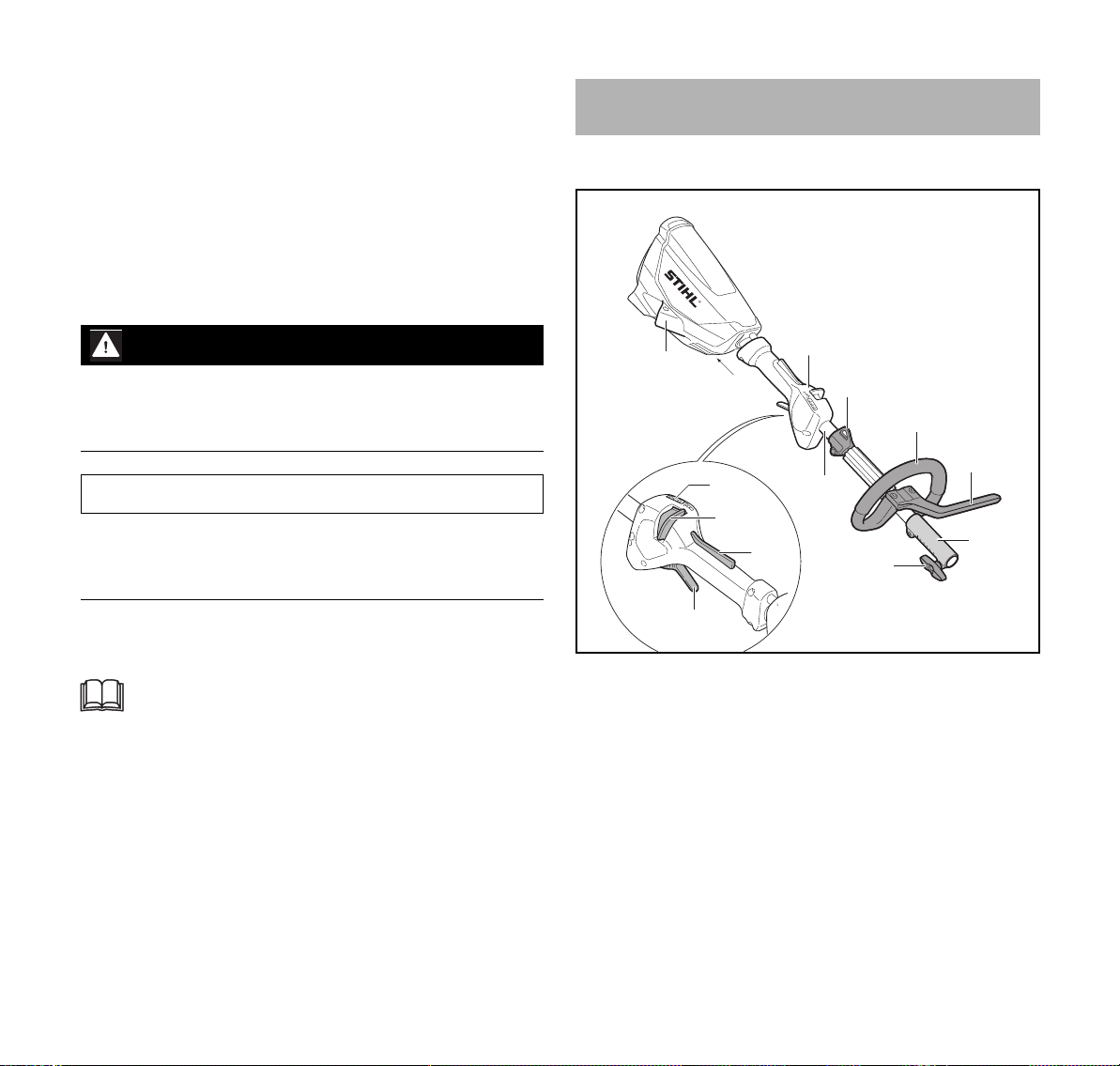
3.1 KombiMotor
2
1
1Buchse
Die Buchse dient zum Einstecken des Steckers der
Anschlussleitung.
2 Bedienungsgriff
Der Bedienungsgriff dient zum Bedienen, Halten und
Führen des KombiMotors.
3LEDs
Die LEDs zeigen die eingestellte Leistungsstufe an.
#
7
9
3
8
4
5
12
6
10
11
0000-GXX-4641-A0
0458-805-9621-A
3
Page 6
deutsch
3 Übersicht
4 Entsperrschieber
Der Entsperrschieber entsperrt zusammen mit der
Schalthebelsperre den Schalthebel. Der
Entsperrschieber dient zum Einstellen der
Leistungsstufe.
5 Schalthebelsperre
Die Schalthebelsperre entsperrt zusammen mit dem
Entsperrschieber den Schalthebel.
6 Schalthebel
Der Schalthebel schaltet den KombiMotor ein und aus.
7Tragöse
Die Tragöse dient zum Einhängen des Tragsystems.
8Schaft
Der Schaft verbindet alle Bauteile.
9 Rundumgriff
Der Rundumgriff dient zum Halten und Führen des
KombiMotors.
10 Schrittbegrenzer
Der Schrittbegrenzer begrenzt den Abstand zwischen
dem Bein des Benutzers und einem MetallSchneidwerkzeug.
11 Kupplungsmuffe
Die Kupplungsmuffe verbindet den KombiMotor mit
einem KombiWerkzeug.
12 Knebelschraube
Die Knebelschraube klemmt das KombiWerkzeug an
den Schaft.
# Leistungsschild mit Maschinennummer
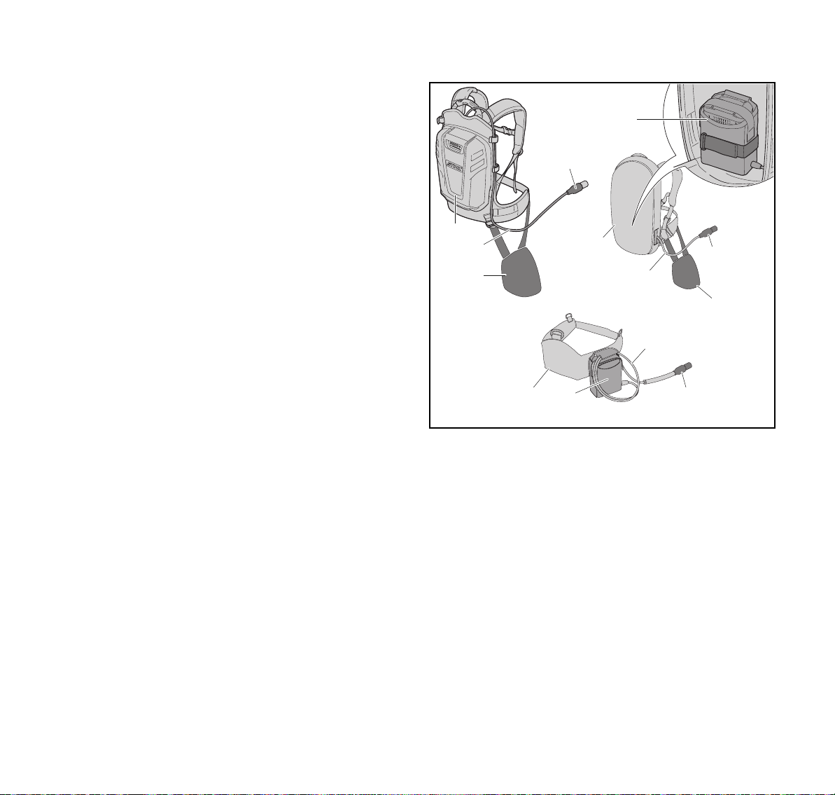
3.2 Tragsysteme
6
4
1
2
3
5
4
2
3
2
7 6
1 Akku STIHL AR
Der Akku STIHL AR kann den KombiMotor mit Energie
versorgen.
2 Anschlussleitung
Die Anschlussleitung verbindet den KombiMotor mit dem
Akku oder der „Gürteltasche AP mit Anschlussleitung“.
3 Anlagepolster
Das Anlagepolster dient zum Befestigen des
KombiMotors am Akku STIHL AR oder des Tragsystems
mit eingebauter „Gürteltasche AP mit Anschlussleitung.
4 Stecker der Anschlussleitung
Der Stecker der Anschlussleitung verbindet den
KombiMotor mit der „Gürteltasche AP mit
Anschlussleitung“ oder einem Akku STIHL AR.
4
0000-GXX-3921-A3
4
0458-805-9621-A
Page 7
4 Sicherheitshinweise
A
deutsch
5 Tragsystem mit eingebauter „Gürteltasche AP mit
Anschlussleitung“
Das Tragsystem kann den KombiMotor mit Energie
versorgen.
6 „Gürteltasche AP mit Anschlussleitung“
Die „Gürteltasche AP mit Anschlussleitung“ kann den
KombiMotor mit Energie versorgen.
7 Akku-Gürtel mit angebauter „Gürteltasche AP mit
Anschlussleitung“
Der Akku-Gürtel kann den KombiMotor mit Energie
versorgen.
3.3 Symbole
Die Symbole können auf dem KombiMotor sein und
bedeuten Folgendes:
Dieses Symbol gibt an, in welche Richtung der
Entsperrschieber geschoben werden muss.
Garantierter Schallleistungspegel nach
L
W
Richtlinie 2000/14/EG in dB(A) um
Schallemissionen von Produkten vergleichbar
zu machen.
Produkt nicht mit dem Hausmüll entsorgen.
4 Sicherheitshinweise
4.1 Warnsymbole
Die Warnsymbole auf dem KombiMotor bedeuten
Folgendes:
Sicherheitshinweise und deren Maßnahmen
beachten.
Gebrauchsanleitung lesen, verstehen und
aufbewahren.
Stecker der Anschlussleitung während
Arbeitsunterbrechungen, des Transports, der
Aufbewahrung, Reinigung, Wartung oder
Reparatur aus der Buchse ziehen.
4.2 Bestimmungsgemäße Verwendung
Der KombiMotor STIHL KMA 130 R dient zum Antrieb von
verschiedenen STIHL KombiWerkzeugen.
Der KombiMotor kann bei Regen verwendet werden.
Der KombiMotor darf nicht im Schnee verwendet werden.
Der KombiMotor wird von einem Akku STIHL AP zusammen
mit der „Gürteltasche AP mit Anschlussleitung“ oder einem
Akku STIHL AR mit Energie versorgt.
WARNUNG
■ Akkus die nicht von STIHL für den KombiMotor
freigegeben sind, können Brände und Explosionen
auslösen. Personen können schwer verletzt oder getötet
werden und Sachschaden kann entstehen.
► KombiMotor mit einem Akku STIHL AP zusammen mit
der „Gürteltasche AP mit Anschlussleitung“ oder einem
Akku STIHL AR verwenden.
■ Falls der KombiMotor oder der Akku nicht
bestimmungsgemäß verwendet wird, können Personen
schwer verletzt oder getötet werden und Sachschaden
kann entstehen.
► KombiMotor so verwenden, wie es in dieser
Gebrauchsanleitung beschrieben ist.
► Akku so verwenden, wie es in der Gebrauchsanleitung
„Gürteltasche AP mit Anschlussleitung“ oder der
Gebrauchsanleitung Akku STIHL AR beschrieben ist.
0458-805-9621-A
5
Page 8
deutsch
4 Sicherheitshinweise
4.3 Anforderungen an den Benutzer
WARNUNG
■ Benutzer ohne eine Unterweisung können die Gefahren
des KombiMotors nicht erkennen oder nicht einschätzen.
Der Benutzer oder andere Personen können schwer
verletzt oder getötet werden.
► Gebrauchsanleitung lesen, verstehen und
aufbewahren.
► Falls der KombiMotor an eine andere Person
weitergegeben wird: Gebrauchsanleitung mitgeben.
► Sicherstellen, dass der Benutzer folgende
Anforderungen erfüllt:
– Der Benutzer ist ausgeruht.
– Der Benutzer ist körperlich, sensorisch und geistig
fähig, den KombiMotor zu bedienen und damit zu
arbeiten. Falls der Benutzer körperlich, sensorisch
oder geistig eingeschränkt dazu fähig ist, darf der
Benutzer nur unter Aufsicht oder nach Anweisung
durch eine verantwortliche Person damit arbeiten.
– Der Benutzer kann die Gefahren des KombiMotors
erkennen und einschätzen.
– Der Benutzer ist volljährig oder der Benutzer wird
entsprechend nationaler Regelungen unter Aufsicht
in einem Beruf ausgebildet.
– Der Benutzer hat eine Unterweisung von einem
STIHL Fachhändler oder einer fachkundigen Person
erhalten, bevor er das erste Mal mit dem KombiMotor
arbeitet.
– Der Benutzer ist nicht durch Alkohol, Medikamente
oder Drogen beeinträchtigt.
► Falls Unklarheiten bestehen: Einen STIHL Fachhändler
aufsuchen.
4.4 Bekleidung und Ausstattung
WARNUNG
■ Während der Arbeit können lange Haare in den
KombiMotor hineingezogen werden. Der Benutzer kann
schwer verletzt werden.
► Lange Haare zusammenbinden und so sichern, dass
sie nicht in den KombiMotor hineingezogen werden
können.
■ Herabfallende Gegenstände können zu Verletzungen des
Kopfs führen.
► Falls während der Arbeit Gegenstände herabfallen
können: Einen Schutzhelm tragen.
■ Während der Arbeit kann Staub aufgewirbelt werden.
Eingeatmeter Staub kann die Gesundheit schädigen und
allergische Reaktionen auslösen.
► Eine Staubschutzmaske tragen.
■ Ungeeignete Bekleidung kann sich in Holz, Gestrüpp und
im KombiMotor verfangen. Benutzer ohne geeignete
Bekleidung können schwer verletzt werden.
► Eng anliegende Bekleidung tragen.
► Schals und Schmuck ablegen.
■ Falls der Benutzer ungeeignetes Schuhwerk trägt, kann er
ausrutschen. Der Benutzer kann verletzt werden.
► Festes, geschlossenes Schuhwerk mit griffiger Sohle
tragen.
4.5 Arbeitsbereich und Umgebung
WARNUNG
■ Unbeteiligte Personen, Kinder und Tiere können die
Gefahren des KombiMotors nicht erkennen und nicht
einschätzen. Unbeteiligte Personen, Kinder und Tiere
können schwer verletzt werden.
► Unbeteiligte Personen, Kinder und Tiere aus dem
Arbeitsbereich fernhalten.
► KombiMotor nicht unbeaufsichtigt lassen.
6
0458-805-9621-A
Page 9

4 Sicherheitshinweise
deutsch
► Sicherstellen, dass Kinder nicht mit dem KombiMotor
spielen können.
■ Elektrische Bauteile des KombiMotors können Funken
erzeugen. Funken können in leicht brennbarer oder
explosiver Umgebung Brände und Explosionen auslösen.
Personen können schwer verletzt oder getötet werden
und Sachschaden kann entstehen.
► Nicht in einer leicht brennbaren und nicht in einer
explosiven Umgebung arbeiten.
4.6 Sicherheitsgerechter Zustand
Der KombiMotor ist im sicherheitsgerechten Zustand, falls
folgende Bedingungen erfüllt sind:
– Der KombiMotor ist unbeschädigt.
– Der KombiMotor ist sauber.
– Die Bedienungselemente funktionieren und sind
unverändert.
– Ein in dieser Gebrauchsanleitung angegebenes
KombiWerkzeug ist angebaut.
– Das KombiWerkzeug ist richtig angebaut.
– Nur original STIHL Zubehör für diesen KombiMotor ist
angebaut.
– Das Zubehör ist richtig angebaut.
WARNUNG
■ In einem nicht sicherheitsgerechten Zustand können
Bauteile nicht mehr richtig funktionieren und
Sicherheitseinrichtungen außer Kraft gesetzt werden.
Personen können schwer verletzt oder getötet werden.
► Mit einem unbeschädigten KombiMotor arbeiten.
► Falls der KombiMotor verschmutzt ist: KombiMotor
reinigen.
► KombiMotor nicht verändern. Ausnahme: Anbau eines
in dieser Gebrauchsanleitung angegebenen
KombiWerkzeugs.
► Falls die Bedienungselemente nicht funktionieren: Nicht
mit dem KombiMotor arbeiten.
► Nur original STIHL Zubehör für diesen KombiMotor
anbauen.
► KombiWerkzeug so anbauen, wie es in der
Gebrauchsanleitung des KombiWerkzeugs
beschrieben ist.
► Zubehör so anbauen, wie es in dieser
Gebrauchsanleitung oder in der Gebrauchsanleitung
des Zubehörs beschrieben ist.
► Gegenstände nicht in die Öffnungen des KombiMotors
stecken.
► Falls Unklarheiten bestehen: Einen STIHL Fachhändler
aufsuchen.
4.7 Arbeiten
WARNUNG
■ Der Benutzer kann in bestimmten Situationen nicht mehr
konzentriert arbeiten. Der Benutzer kann stolpern, fallen
und schwer verletzt werden.
► Ruhig und überlegt arbeiten.
► Falls die Lichtverhältnisse und Sichtverhältnisse
schlecht sind: Nicht mit dem KombiMotor arbeiten.
► KombiMotor alleine bedienen.
► Auf Hindernisse achten.
► Auf dem Boden stehend arbeiten und das
Gleichgewicht halten.
► Falls Ermüdungserscheinungen auftreten: Eine
Arbeitspause einlegen.
■ Falls sich der KombiMotor während der Arbeit verändert
oder sich ungewohnt verhält, kann der KombiMotor in
einem nicht sicherheitsgerechten Zustand sein. Personen
können schwer verletzt werden und Sachschaden kann
entstehen.
► Arbeit beenden, Stecker der Anschlussleitung aus der
Buchse ziehen und einen STIHL Fachhändler
aufsuchen.
■ Während der Arbeit können Vibrationen durch den
KombiMotor entstehen.
0458-805-9621-A
7
Page 10
deutsch
4 Sicherheitshinweise
► Handschuhe tragen.
► Arbeitspausen machen.
► Falls Anzeichen einer Durchblutungsstörung auftreten:
Einen Arzt aufsuchen.
■ In einer Gefahrensituation kann der Benutzer in Panik
geraten und das Tragsystem nicht ablegen. Der Benutzer
kann schwer verletzt werden.
► Ablegen des Tragsystems üben.
4.8 Transportieren
WARNUNG
■ Während des Transports kann der KombiMotor umkippen
oder sich bewegen. Personen können verletzt werden und
Sachschaden kann entstehen.
► Stecker der Anschlussleitung aus der
Buchse ziehen.
► Falls ein KombiWerkzeug angebaut ist: KombiMotor so
transportieren, wie es in der Gebrauchsanleitung des
angebauten KombiWerkzeugs beschrieben ist.
► KombiMotor mit Spanngurten, Riemen oder einem Netz
so sichern, dass er nicht umkippen und sich nicht
bewegen kann.
4.9 Aufbewahren
WARNUNG
■ Kinder können die Gefahren des KombiMotors nicht
erkennen und nicht einschätzen. Kinder können schwer
verletzt werden.
► Stecker der Anschlussleitung aus der
Buchse ziehen.
► KombiMotor außerhalb der Reichweite von Kindern
aufbewahren.
■ Die elektrischen Kontakte am KombiMotor und
metallische Bauteile können durch Feuchtigkeit
korrodieren. Der KombiMotor kann beschädigt werden.
► Stecker der Anschlussleitung aus der
Buchse ziehen.
► KombiMotor sauber und trocken aufbewahren.
4.10 Reinigen, Warten und Reparieren
WARNUNG
■ Falls während der Reinigung, Wartung oder Reparatur der
Stecker der Anschlussleitung eingesteckt ist, kann der
KombiMotor unbeabsichtigt eingeschaltet werden.
Personen können schwer verletzt werden und
Sachschaden kann entstehen.
► Stecker der Anschlussleitung aus der
Buchse ziehen.
■ Scharfe Reinigungsmittel, das Reinigen mit einem
Wasserstrahl oder spitze Gegenstände können den
KombiMotor beschädigen. Falls der KombiMotor nicht
richtig gereinigt wird, können Bauteile nicht mehr richtig
8
0458-805-9621-A
Page 11

5 KombiMotor einsatzbereit machen
deutsch
funktionieren und Sicherheitseinrichtungen außer Kraft
gesetzt werden. Personen können schwer verletzt
werden.
► KombiMotor so reinigen, wie es in dieser
Gebrauchsanleitung beschrieben ist.
■ Falls der KombiMotor nicht richtig gewartet oder repariert
wird, können Bauteile nicht mehr richtig funktionieren und
Sicherheitseinrichtungen außer Kraft gesetzt werden.
Personen können schwer verletzt oder getötet werden.
► KombiMotor nicht selbst warten oder reparieren.
► Falls der KombiMotor gewartet oder repariert werden
muss: Einen STIHL Fachhändler aufsuchen.
■ Während der Reinigung oder Wartung der
Schneidwerkzeuge kann der Benutzer sich an scharfen
Schneidkanten schneiden. Der Benutzer kann verletzt
werden.
► Arbeitshandschuhe aus
widerstandsfähigem Material tragen.
5 KombiMotor einsatzbereit machen
5.1 KombiMotor einsatzbereit machen
Vor jedem Arbeitsbeginn müssen folgende Schritte
durchgeführt werden:
► Sicherstellen, dass sich folgende Bauteile im
sicherheitsgerechten Zustand befinden:
– KombiMotor, @ 4.6.
– KombiWerkzeug, wie es in der Gebrauchsanleitung des
KombiWerkzeugs beschrieben ist.
– Akku, wie es in der Gebrauchsanleitung Akku STIHL AR
oder wie in der Gebrauchsanleitung „Gürteltasche AP
mit Anschlussleitung“ beschrieben ist.
► Akku so prüfen, wie es in der Gebrauchsanleitung Akku
STIHL AR oder in der Gebrauchsanleitung „Gürteltasche
AP mit Anschlussleitung“ beschrieben ist.
► Akku vollständig laden, wie es in der Gebrauchsanleitung
Ladegeräte STIHL AL 101, 300, 500 beschrieben ist.
► KombiMotor reinigen, @ 15.
► Rundumgriff anbauen, @ 6.1.
► Falls ein FS-KM mit einem Metallschneidwerkzeug
verwendet wird: Schrittbegrenzer anbauen, @ 6.2.
► KombiWerkzeug so anbauen, wie es in der
Gebrauchsanleitung des KombiWerkzeugs beschrieben
ist.
► Akku STIHL AR, Tragsystem oder „Gürteltasche AP mit
Anschlussleitung“ anlegen und einstellen, @ 7.
► Rundumgriff einstellen, @ 7.4.
► Bedienungselemente prüfen, @ 10.1.
► Falls während der Prüfung der Bedienungselemente
3 LEDs am Akku rot blinken: Stecker der
Anschlussleitung aus der Buchse ziehen und einen
STIHL Fachhändler aufsuchen.
Im KombiMotor besteht eine Störung.
► Falls die Schritte nicht durchgeführt werden können:
KombiMotor nicht verwenden und einen STIHL
Fachhändler aufsuchen.
0458-805-9621-A
9
Page 12
deutsch
5
0000-GXX-3083-A1
4
6
7
1
2
3
6 KombiMotor zusammenbauen
6 KombiMotor zusammenbauen
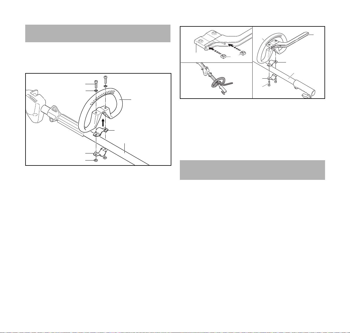
6.1 Rundumgriff anbauen
► KombiMotor ausschalten und Stecker der
Anschlussleitung aus der Buchse ziehen.
► Schelle (4) in den Rundumgriff (3) legen.
► Rundumgriff (3) zusammen mit der Schelle (4) auf den
Schaft (5) setzen.
► Scheiben (2) auf die Schrauben (1) setzen.
► Schelle (6) gegen den Schaft (5) drücken.
► Schrauben (1) durch die Bohrungen im Rundumgriff (3)
und in den Schellen (4 und 6) führen.
► Muttern (7) aufdrehen und fest anziehen.
Der Rundumgriff darf nicht wieder abgebaut werden.
3
1
2
4
5
6
7
8
► Muttern (2) so in den Schrittbegrenzer (1) stecken, dass
die Bohrungen fluchten.
► Schelle (5) in den Rundumgriff (3) legen.
► Rundumgriff (3) zusammen mit der Schelle (5) und dem
Schrittbegrenzer (4) auf den Schaft (6) setzen.
► Schelle (7) gegen den Schaft (6) drücken.
► Schrauben (8) eindrehen und fest anziehen.
7 KombiMotor für den Benutzer
einstellen
7.1 Verwendung mit Akku STIHL AR
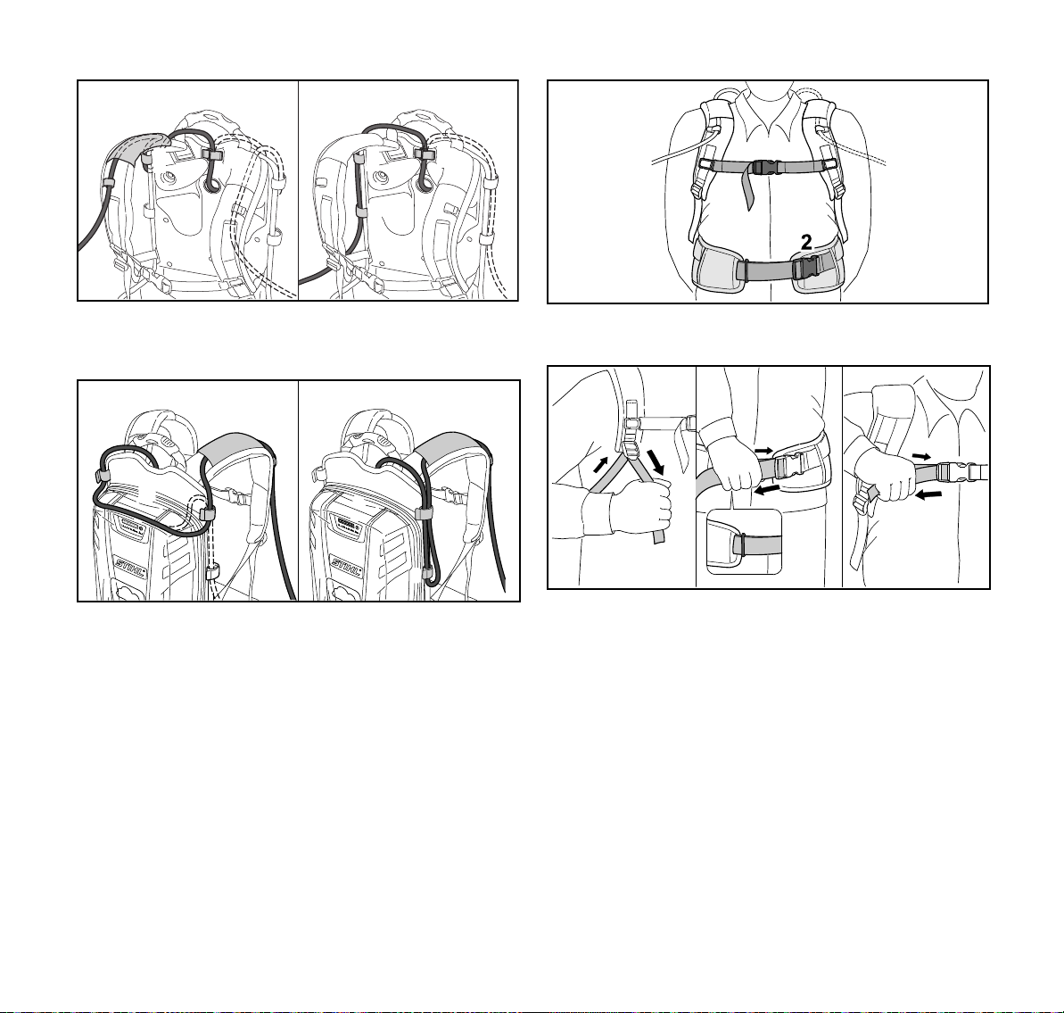
7.1.1 Anschlussleitung verlegen und einstellen Die Anschlussleitung kann abhängig von der Körpergröße
des Benutzers und der Anwendung verlegt und eingestellt
werden.
0000-GXX-4642-A0
6.2 Rundumgriff mit Schrittbegrenzer anbauen
► KombiMotor ausschalten und Stecker der
Anschlussleitung aus der Buchse ziehen.
10
0458-805-9621-A
Page 13
7 KombiMotor für den Benutzer einstellen
0000-GXX-2803-A0
4
3
1
0000-GXX-2828-A0
0000-GXX-2815-A1
3
1
deutsch
2
2
2
2
2
2
Die Anschlussleitung kann durch die Führung (1) am
Traggurt und die Schnallen (2) oder seitlich an der
Rückenplatte mit den Schnallen (2) befestigen werden.
Die Länge der Anschlussleitung kann über eine Schlaufe auf
der Rückenplatte (3) oder eine seitliche Schlaufe (4)
eingestellt werden.
► Anschlussleitung so verlegen, dass sie so kurz wie
möglich ist und das Arbeiten nicht behindert.
0000-GXX-2801-A0
► Verschluss (2) des Hüftgurts schließen.
► Verschluss (1) des Brustgurts schließen.
► Gurte straffen bis der Hüftgurt an der Hüfte und das
Rückenpolster am Rücken anliegt.
► Gurtende des Hüftgurts durch die Öse (3) fädeln.
► Anlagepolster so anbauen, wie es im Beilageblatt des
Anlagepolsters beschrieben ist.
7.1.2 Tragsystem anlegen und einstellen
► Akku auf den Rücken setzen.
0458-805-9621-A
11
Page 14
deutsch
21
0000-GXX-3953-A0
3
4
0000-GXX-3954-A0
1 2
3
4
5
6
7
1
0000-GXX-2828-A0
1
2
► Traggurt (1) so einstellen, dass sich der
Karabinerhaken (2) etwa eine Handbreit unterhalb der
rechten Hüfte befindet.
7.2 Verwendung mit Tragsystem
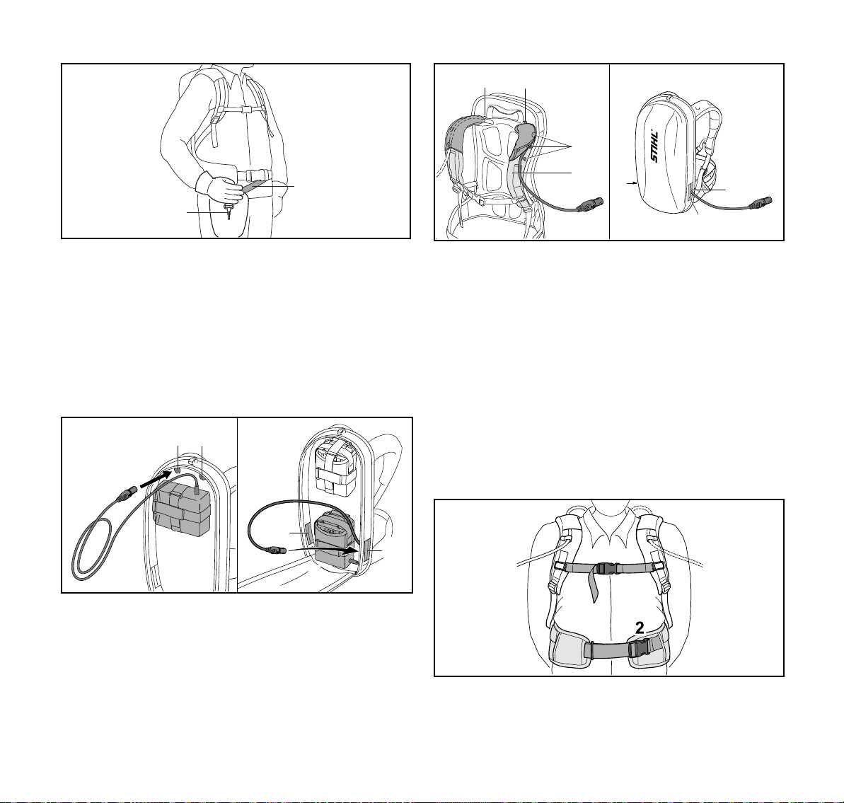
7.2.1 Anschlussleitung verlegen und einstellen Die Anschlussleitung kann abhängig von der Körpergröße
des Benutzers und der Anwendung verlegt und eingestellt
werden.
7 KombiMotor für den Benutzer einstellen
0000-GXX-3033-A1
► Falls die Anschlussleitung durch die obere linke
Öffnung (1) oder die obere rechte Öffnung (2) geführt
wird:
► Druckknöpfe (5) öffnen.
► Anschlussleitung über den Schultergurt (6) führen.
► Druckknöpfe (5) schließen.
► Falls die Anschlussleitung durch die untere linke
Öffnung (3) oder die untere rechte Öffnung (4) geführt
wird: Verwendete Öffnung (3 oder 4) mit dem
Klettverschluss (7) verschließen.
► Anschlussleitung so verlegen, dass sie so kurz wie
möglich ist und das Arbeiten nicht behindert.
Die Anschlussleitung kann durch folgende Öffnungen
geführt werden:
– die obere linke Öffnung (1)
– die obere rechte Öffnung (2)
– die untere linke Öffnung (3)
– die untere rechte Öffnung (4)
12
7.2.2 Tragsystem anlegen und einstellen
► Akku auf den Rücken setzen.
► Verschluss (2) des Hüftgurts schließen.
► Verschluss (1) des Brustgurts schließen.
0458-805-9621-A
Page 15
7 KombiMotor für den Benutzer einstellen
0000-GXX-2815-A1
3
1
0000-GXX-3660-A1
3
2
1
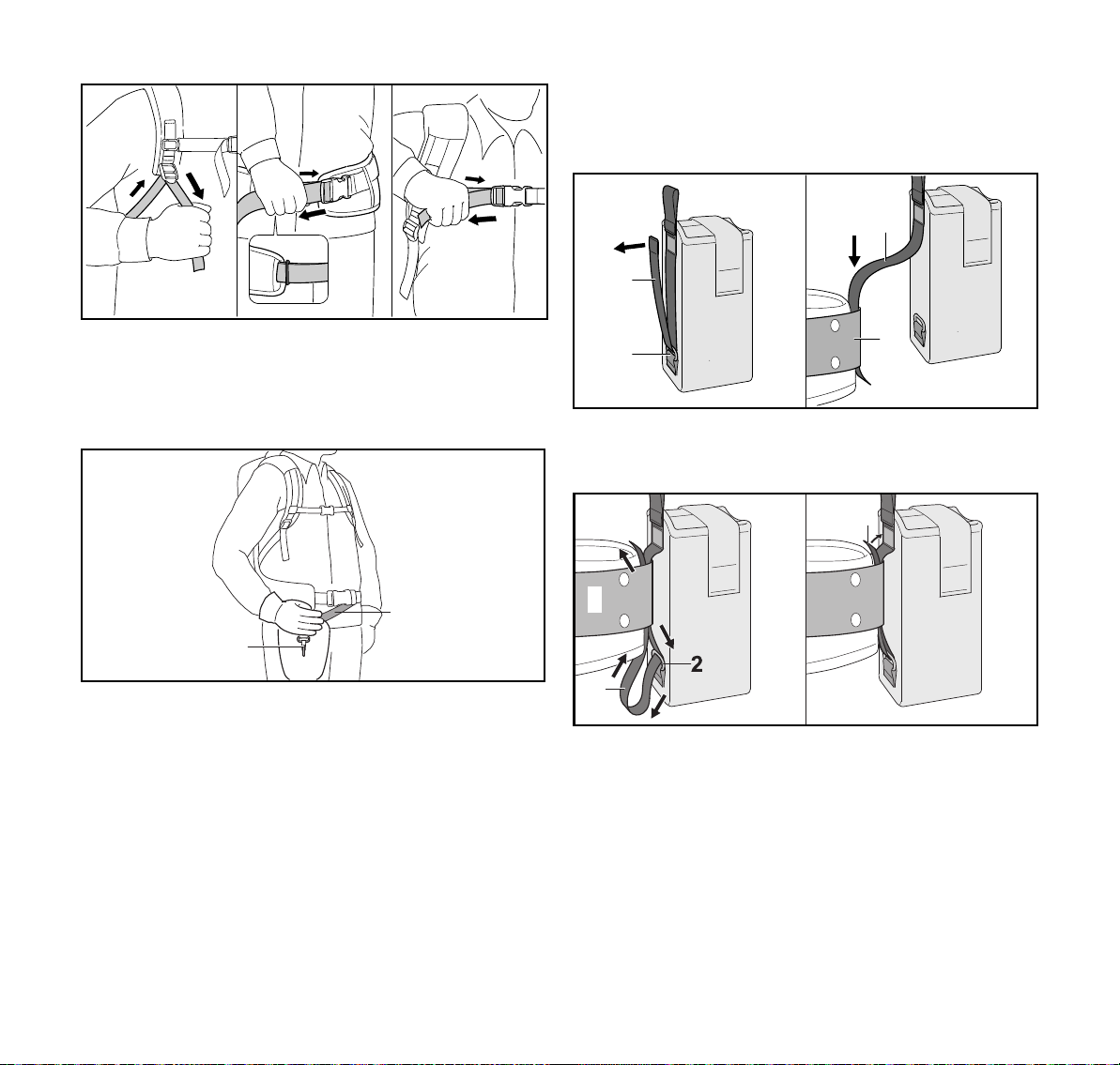
► Gurte straffen bis der Hüftgurt an der Hüfte und das
Rückenpolster am Rücken anliegt.
► Gurtende des Hüftgurts durch die Öse (3) fädeln.
► Anlagepolster so anbauen, wie es im Beilageblatt des
Anlagepolsters beschrieben ist.
deutsch
7.3 Verwendung mit „Gürteltasche AP mit Anschlussleitung“
7.3.1 „Gürteltasche AP mit Anschlussleitung“ anbauen
► Klettverschluss am Gurt (1) öffnen und den Gurt (1) aus
der Öse (2) ziehen.
► Gurt (1) durch den Gürtel (3) führen.
1
1
2
► Traggurt (1) so einstellen, dass sich der
Karabinerhaken (2) etwa eine Handbreit unterhalb der
rechten Hüfte befindet.
0458-805-9621-A
3
0000-GXX-3033-A1
1
0000-GXX-3416-A2
► Gurt (1) durch die Öse (2) und den Gürtel (3)
zurückführen.
► Klettverschluss am Gurt (1) schließen.
13
Page 16
deutsch
4
0000-GXX-3417-A2
6
5
2
0000-GXX-3418-A0
1
3
0000-GXX-3926-A1
1
2
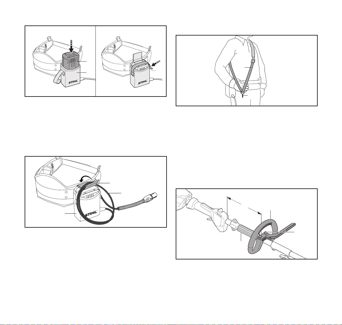
► Akku (4) bis zum Anschlag in die Gürteltasche (5)
drücken.
Ein kurzer Signalton ertönt.
► Akku (4) mit dem Klettverschluss (6) sichern.
7.3.2 Anschlussleitung einstellen
Die Anschlussleitung kann abhängig von der Körpergröße
des Benutzers und der Anwendung eingestellt werden.
7 KombiMotor für den Benutzer einstellen
7.3.3 Tragsystem anlegen und einstellen
► Einschultergurt (1) aufsetzen.
► Einschultergurt (1) so einstellen, dass sich der
Karabinerhaken (2) etwa eine Handbreit unterhalb der
rechten Hüfte befindet.
7.4 Rundumgriff ausrichten und einstellen
Der Rundumgriff kann abhängig von der Anwendung und
der Körpergröße des Benutzers in verschiedene Positionen
eingestellt werden.
► KombiMotor ausschalten und Stecker der
Anschlussleitung aus der Buchse ziehen.
Die Länge der Anschlussleitung kann über eine Schlaufe (1)
eingestellt und mit der Schnalle (2) an der Gürteltasche (3)
befestigt werden.
► Anschlussleitung so verlegen, dass sie so kurz wie
möglich ist und das Arbeiten nicht behindert.
14
a
1
3
► Schrauben (2) lösen.
► Rundumgriff (1) so in die gewünschte Position
verschieben, dass folgende Bedingungen erfüllt sind:
0458-805-9621-A
2
0000-GXX-4643-A0
Page 17

8 Stecker der Anschlussleitung einstecken und ausstecken
0000-GXX-3086-A0
2
1
0000-GXX-3087-A0
2
1
1
0000-GXX-3088-A0
1
3
2
deutsch
– Der Abstandhalter (3) passt zwischen den
Rundumgriff (1) und die Tragöse.
– a = maximal 25 cm
► Schrauben (2) so fest anziehen, dass der Rundumgriff (1)
nicht mehr um den Schaft gedreht werden kann.
8 Stecker der Anschlussleitung
einstecken und ausstecken
8.1 Stecker der Anschlussleitung einstecken
► Stecker (2) der Anschlussleitung so ausrichten, dass der
Pfeil am Stecker (2) der Anschlussleitung auf den Pfeil an
der Buchse (1) zeigt.
► Stecker (2) der Anschlussleitung in die Buchse (1)
stecken.
Der Stecker (2) der Anschlussleitung rastet ein.
8.2 Stecker der Anschlussleitung herausziehen
► Stecker (2) der Anschlussleitung mit der Hand greifen.
► Stecker (2) der Anschlussleitung aus der Buchse (1)
ziehen.
9 KombiMotor einschalten und
ausschalten
9.1 KombiMotor einschalten
► KombiMotor mit der rechten Hand am Bedienungsgriff so
festhalten, dass der Daumen den Bedienungsgriff
umschließt.
► KombiMotor mit der linken Hand am Rundumgriff so
festhalten, dass der Daumen den Rundumgriff
umschließt.
0458-805-9621-A
15
Page 18

deutsch
10 KombiMotor prüfen
► Entsperrschieber (1) mit dem Daumen in Richtung
Rundumgriff schieben und halten.
► Schalthebelsperre (2) mit der Hand drücken und gedrückt
halten.
Der Entsperrschieber (1) kann losgelassen werden
► Schalthebel (3) mit dem Zeigefinger drücken und gedrückt
halten.
Der KombiMotor beschleunigt und das KombiWerkzeug
wird angetrieben.
Je weiter der Schalthebel gedrückt ist, umso schneller wird
das KombiWerkzeug angetrieben.
9.2 KombiMotor ausschalten
► Schalthebel und Schalthebelsperre loslassen.
► Warten, bis das KombiWerkzeug nicht mehr angetrieben
wird.
► Falls das KombiWerkzeug weiterhin angetrieben wird:
Stecker der Anschlussleitung aus der Buchse ziehen und
einen STIHL Fachhändler aufsuchen.
Der KombiMotor ist defekt.
10 KombiMotor prüfen
► Schalthebel und Schalthebelsperre loslassen.
► Falls der Schalthebel oder die Schalthebelsperre
schwergängig sind oder nicht in die Ausgangsposition
zurückfedern: KombiMotor nicht verwenden und einen
STIHL Fachhändler aufsuchen.
Der Schalthebel oder die Schalthebelsperre ist defekt.
KombiMotor einschalten
► Stecker der Anschlussleitung einstecken.
► Entsperrschieber in Richtung Rundumgriff schieben und
halten.
► Schalthebelsperre drücken und gedrückt halten.
► Schalthebel drücken und gedrückt halten.
Das KombiWerkzeug bewegt sich.
► Falls 3 LEDs rot blinken: Stecker der Anschlussleitung
aus der Buchse ziehen und einen STIHL Fachhändler
aufsuchen.
Im KombiMotor besteht eine Störung.
► Schalthebel und Schalthebelsperre loslassen.
Das KombiWerkzeug wird nicht mehr angetrieben.
► Falls das KombiWerkzeug weiterhin angetrieben wird:
Stecker der Anschlussleitung aus der Buchse ziehen und
einen STIHL Fachhändler aufsuchen.
Der KombiMotor ist defekt.
10.1 Bedienungselemente prüfen
Entsperrschieber, Schalthebelsperre und Schalthebel
► Stecker der Anschlussleitung aus der Buchse ziehen.
► Versuchen, den Schalthebel zu drücken, ohne den
Entsperrschieber und die Schalthebelsperre zu drücken.
► Falls sich der Schalthebel drücken lässt: KombiMotor
nicht verwenden und einen STIHL Fachhändler
aufsuchen.
Der Entsperrschieber oder die Schalthebelsperre sind
defekt.
► Entsperrschieber in Richtung Rundumgriff schieben und
halten.
► Schalthebelsperre drücken und gedrückt halten.
► Schalthebel drücken.
16
11 Mit dem KombiMotor arbeiten
11.1 KombiMotor halten und führen
Abhängig vom angebauten KombiWerkzeug und der
Anwendung muss der KombiMotor unterschiedlich gehalten
und geführt werden.
► KombiMotor so halten und führen, wie es in der
Gebrauchsanleitung des angebauten KombiWerkzeugs
beschrieben ist.
0458-805-9621-A
Page 19
12 Nach dem Arbeiten
0000-GXX-3090-A0
1
deutsch
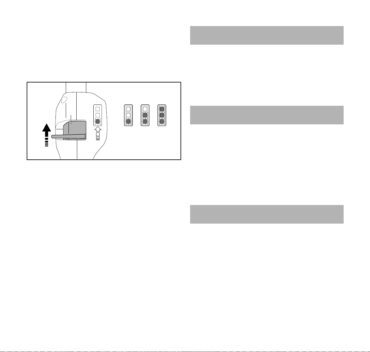
11.2 Leistungsstufe einstellen
Abhängig von der Anwendung können 3 Leistungsstufen
eingestellt werden. Die LEDs zeigen die eingestellte
Leistungsstufe an. Je höher die Leistungsstufe, umso
schneller kann das KombiWerkzeug angetrieben werden.
Die eingestellte Leistungsstufe beeinflusst die Akkulaufzeit.
Je niedriger die Leistungsstufe, umso länger ist die
Akkulaufzeit.
► Entsperrschieber (1) mit dem Daumen in Richtung
Rundumgriff schieben und halten.
Die LEDs zeigen die eingestellte Leistungsstufe an.
► Entsperrschieber (1) nach vorne drücken, kurz halten und
zurück federn lassen.
Die nächste Leistungsstufe ist eingestellt. Nach der dritten
Leistungsstufe folgt wieder die erste Leistungsstufe.
► Entsperrschieber (1) so oft nach vorne drücken und
zurück federn lassen, bis die gewünschte Leistungsstufe
eingestellt ist.
Jedes KombiWerkzeug kann mit jeder eingestellten
Leistungsstufe verwendet werden.
11.3 Arbeiten
Abhängig vom angebauten KombiWerkzeug kann mit dem
KombiMotor unterschiedlich gearbeitet werden.
► So arbeiten, wie es in der Gebrauchsanleitung des
angebauten KombiWerkzeugs beschrieben ist.
12 Nach dem Arbeiten
12.1 Nach dem Arbeiten
► KombiMotor ausschalten und Stecker der
Anschlussleitung aus der Buchse ziehen.
► Falls der KombiMotor nass ist: KombiMotor trocknen
lassen.
► KombiMotor reinigen.
13 Transportieren
13.1 KombiMotor transportieren
► KombiMotor ausschalten und Stecker der
Anschlussleitung aus der Buchse ziehen.
► KombiMotor mit einer Hand so am Schaft tragen, dass das
KombiWerkzeug nach hinten zeigt und der KombiMotor
ausbalanciert ist.
► Falls der KombiMotor in einem Fahrzeug transportiert
wird: KombiMotor so sichern, dass der KombiMotor nicht
umkippen und sich nicht bewegen kann.
14 Aufbewahren
14.1 KombiMotor aufbewahren
► KombiMotor ausschalten und Stecker der
Anschlussleitung aus der Buchse ziehen.
► KombiWerkzeug so abbauen, wie es in der
Gebrauchsanleitung des KombiWerkzeugs beschrieben
ist.
► KombiMotor so aufbewahren, dass folgende Bedingungen
erfüllt sind:
– Der KombiMotor ist außerhalb der Reichweite von
Kindern.
– Der KombiMotor ist sauber und trocken.
0458-805-9621-A
17
Page 20

deutsch
15 Reinigen
15.1 KombiMotor reinigen
► KombiMotor ausschalten und Stecker der
Anschlussleitung aus der Buchse ziehen.
► KombiMotor mit einem feuchten Tuch reinigen.
16 Warten und Reparieren
16.1 KombiMotor warten und reparieren
Der Benutzer kann den KombiMotor nicht selbst warten und
nicht reparieren.
► Falls der KombiMotor gewartet werden muss oder defekt
oder beschädigt ist: Einen STIHL Fachhändler aufsuchen.
15 Reinigen
18
0458-805-9621-A
Page 21

17 Störungen beheben
17 Störungen beheben
17.1 Störungen des KombiMotors und des Akkus beheben
Störung LEDs am Akku Ursache Abhilfe
Der KombiMotor läuft
beim Einschalten
nicht an.
Der KombiMotor
schaltet im Betrieb
ab.
1 LED blinkt grün. Der Ladezustand des
Akkus ist zu gering.
1 LED leuchtet rot. Der Akku ist zu warm oder
zu kalt.
3 LEDs blinken rot. Im KombiMotor besteht
eine Störung.
3 LEDs leuchten
rot.
4 LEDs blinken rot. Im Akku besteht eine
3 LEDs leuchten
rot.
Der KombiMotor ist zu
warm.
Störung.
Die elektrische Verbindung
zwischen dem KombiMotor
und dem Akku ist
unterbrochen.
Der KombiMotor oder der
Akku sind feucht.
Der KombiMotor ist zu
warm.
► Akku so laden, wie es in der Gebrauchsanleitung
Ladegeräte STIHL AL 101, 300, 500 beschrieben
ist.
► Stecker der Anschlussleitung aus der Buchse
ziehen.
► Akku abkühlen oder erwärmen lassen.
► Stecker der Anschlussleitung aus der Buchse
ziehen und erneut einstecken
► KombiMotor einschalten.
► Falls weiterhin 3 LEDs rot blinken: KombiMotor
nicht verwenden und einen STIHL Fachhändler
aufsuchen.
► Stecker der Anschlussleitung aus der Buchse
ziehen.
► KombiMotor abkühlen lassen.
► Stecker der Anschlussleitung aus der Buchse
ziehen und erneut einstecken.
► KombiMotor einschalten.
► Falls weiterhin 4 LEDs rot blinken: Akku nicht
verwenden und einen STIHL Fachhändler
aufsuchen.
► Stecker der Anschlussleitung aus der Buchse
ziehen und erneut einstecken.
► Falls weiterhin der KombiMotor beim Einschalten
nicht anläuft: Kontaktflächen der Anschlussleitung
reinigen, wie es in der Gebrauchsanleitung Akku
STIHL AR oder „Gürteltasche AP mit
Anschlussleitung“ beschrieben ist.
► KombiMotor oder Akku trocknen lassen.
► Stecker der Anschlussleitung aus der Buchse
ziehen.
► KombiMotor abkühlen lassen.
deutsch
0458-805-9621-A
19
Page 22

deutsch
Störung LEDs am Akku Ursache Abhilfe
Es besteht eine elektrische
Störung.
► Stecker der Anschlussleitung aus der Buchse
ziehen und erneut einstecken.
► Falls weiterhin der KombiMotor im Betrieb
abschaltet: Kontaktflächen der Anschlussleitung
reinigen, wie es in der Gebrauchsanleitung Akku
STIHL AR oder „Gürteltasche AP mit
Anschlussleitung“ beschrieben ist.
► KombiMotor einschalten.
Die Betriebszeit des
KombiMotors ist zu
kurz.
Der Akku ist nicht
vollständig geladen.
Die Lebensdauer des
► Akku vollständig laden, wie es in der
Gebrauchsanleitung Ladegeräte STIHL AL 101,
300, 500 beschrieben ist.
► Akku ersetzen.
Akkus ist überschritten.
17 Störungen beheben
20
0458-805-9621-A
Page 23

18 Technische Daten
deutsch
18 Technische Daten
18.1 KombiMotor STIHL KMA 130 R
– Zulässige Akkus:
–STIHL AR
– STIHL AP zusammen mit „Gürteltasche AP mit
Anschlussleitung
– Gewicht ohne KombiWerkzeug: 3,2 kg
Die Laufzeit ist unter www.stihl.com/battery-life angegeben.
18.2 Schallwerte und Vibrationswerte
STIHL empfiehlt, einen Gehörschutz zu tragen.
Die genauen Schallwerte und Vibrationswerte sind abhängig
vom angebauten KombiWerkzeug und in der
Gebrauchsanleitung des KombiWerkzeugs beschrieben.
– Schalldruckpegel L
ISO 11201, ISO 22868: 76 dB(A) bis 91 dB(A). Der KWert für den Schalldruckpegel beträgt 2 dB(A).
– Schallleistungspegel L
ISO 10517, ISO 22868: 86 dB(A) bis 102 dB(A). Der KWert für den Schallleistungspegel beträgt 2 dB(A).
– Vibrationswert a
ISO 11789, ISO 20643, ISO 22867
– Bedienungsgriff: 1,5 m/s² bis 5,0 m/s². Der K-Wert für
den Vibrationswert beträgt 2,0 m/s².
– Rundumgriff: 2,0 m/s² bis 5,0 m/s². Der K-Wert für den
Vibrationswert beträgt 2 m/s².
Die angegebenen Vibrationswerte wurden nach einem
genormten Prüfverfahren gemessen und können zum
Vergleich von Elektrogeräten herangezogen werden. Die
tatsächlich auftretenden Vibrationswerte können von den
angegebenen Werten abweichen, abhängig von der Art der
Anwendung. Die angegebenen Vibrationswerte können zu
einer ersten Einschätzung der Vibrationsbelastung
verwendet werden. Die tatsächliche Vibrationsbelastung
gemessen nach ISO 10517,
pA
gemessen nach ISO 3744,
wA
gemessen nach ISO 8662, ISO 10517,
hv
muss eingeschätzt werden. Dabei können auch die Zeiten
berücksichtigt werden, in denen das Elektrogerät
abgeschaltet ist, und solche, in denen es zwar eingeschaltet
ist, aber ohne Belastung läuft.
Informationen zur Erfüllung der Arbeitgeberrichtlinie
Vibration 2002/44/EG sind unter www.stihl.com/vib
angegeben.
18.3 REACH
REACH bezeichnet eine EG-Verordnung zur Registrierung,
Bewertung und Zulassung von Chemikalien.
Informationen zur Erfüllung der REACH Verordnung sind
unter www.stihl.com/reach angegeben.
19 Kombinationen mit KombiWerkzeugen
19.1 STIHL KMA 130 R
Folgende KombiWerkzeuge dürfen angebaut werden:
– STIHL BG-KM: Blasgerät
– STIHL BF-KM: Bodenfräse
– STIHL FCB-KM: Kantenschneider
– STIHL FCS-KM: Kantenschneider
– STIHL FH-KM 145°: Gestrüppschneider
– STIHL FS-KM: Motorsense
– STIHL HT-KM: Hoch-Entaster
– STIHL HL-KM 0°: Heckenschneider
– STIHL HL-KM 145°: Heckenschneider
–STIHL KB-KM: Kehrbürste
– STIHL KW-KM: Kehrwalze
– STIHL SP-KM: Spezialernter
0458-805-9621-A
21
Page 24

deutsch
20 Ersatzteile und Zubehör
STIHL FS-KM
Der KombiMotor kann zusammen mit dem STIHL FS-KM mit
folgenden Schneidwerkzeugen verwendet werden:
Mähkopf mit Mähfäden „rund, leise“ mit Durchmesser
2,4 mm:
– Mähkopf AutoCut 25-2
– Mähkopf AutoCut C 26-2
– Mähkopf DuroCut 20-2
– Mähkopf FixCut 31-2
– Mähkopf PolyCut 27-3
– Mähkopf SuperCut 20-2
– Mähkopf TrimCut 31-2
Mähkopf mit Mähfäden „rund, leise“ mit Durchmesser
2,7 mm:
– Mähkopf AutoCut 36-2
Metall-Schneidwerkzeuge:
– Grasschneideblatt 230-2
– Grasschneideblatt 230-4
– Grasschneideblatt 230-8
– Grasschneideblatt 260-2
– Dickichtmesser 250-3
Schutze, Griffe und Tragsysteme, die mit den genannten
Schneidwerkzeugen verwendet werden müssen, sind in der
Gebrauchsanleitung STIHL FS-KM angegeben.
20 Ersatzteile und Zubehör
20.1 Ersatzteile und Zubehör
Diese Symbole kennzeichnen original STIHL
Ersatzteile und original STIHL Zubehör.
STIHL empfiehlt, original STIHL Ersatzteile und original
STIHL Zubehör zu verwenden.
Original STIHL Ersatzteile und original STIHL Zubehör sind
bei einem STIHL Fachhändler erhältlich.
21 Entsorgen
21.1 KombiMotor entsorgen
Informationen zur Entsorgung sind bei einem STIHL
Fachhändler erhältlich.
► KombiMotor, Zubehör und Verpackung vorschriftsmäßig
und umweltfreundlich entsorgen.
22 EU-Konformitätserklärung
22.1 KombiMotor STIHL KMA 130 R
ANDREAS STIHL AG & Co. KG
Badstraße 115
D-71336 Waiblingen
Deutschland
erklärt in alleiniger Verantwortung, dass
– Bauart: Akku-KombiMotor
– Fabrikmarke: STIHL
– Typ: KMA 130 R
– Serienidentifizierung: 4867
den einschlägigen Bestimmungen der Richtlinien
2011/65/EU, 2006/42/EG, 2014/30/EU und 2000/14/EG
entspricht und in Übereinstimmung mit den jeweils zum
Produktionsdatum gültigen Versionen der folgenden
Normen in Verbindung mit den in dieser
Gebrauchsanleitung genannten KombiWerkzeugen
entwickelt und gefertigt worden ist: EN 55014-1,
EN 55014-2, EN 60335-1, EN 60745- 1 und EN ISO 12100
22
0458-805-9621-A
Page 25

23 Anschriften
deutsch
unter Berücksichtigung der Normen EN 60335-2-72,
EN 50636-2-91, EN 50636-2-100, EN 60745- 2-13 und
EN 60745-2-15.
Der in dieser Gebrauchsanleitung beschriebene
KombiMotor darf nur in Verbindung mit einem in dieser
Gebrauchsanleitung genannten KombiWerkzeug in Betrieb
genommen werden.
Die Technischen Unterlagen sind bei der Produktzulassung
der ANDREAS STIHL AG & Co. KG aufbewahrt.
Das Baujahr, das Herstellungsland und die
Maschinennummer sind auf dem KombiMotor angegeben.
Waiblingen, 01.11.2017
ANDREAS STIHL AG & Co. KG
i. V.
Thomas Elsner, Leiter Produktmanagement und Services
23 Anschriften
23.1 STIHL Hauptverwaltung
ANDREAS STIHL AG & Co. KG
Postfach 1771
D-71307 Waiblingen
23.2 STIHL Vertriebsgesellschaften
DEUTSCHLAND
STIHL Vertriebszentrale AG & Co. KG
Robert-Bosch-Straße 13
64807 Dieburg
Telefon: +49 6071 3055358
Fachmarktstraße 7
2334 Vösendorf
Telefon: +43 1 86596370
SCHWEIZ
STIHL Vertriebs AG
Isenrietstraße 4
8617 Mönchaltorf
Telefon: +41 44 9493030
TSCHECHISCHE REPUBLIK
Andreas STIHL, spol. s r.o.
Chrlická 753
664 42 Modřice
23.3 STIHL Importeure
BOSNIEN-HERZEGOWINA
UNIKOMERC d. o. o.
Bišće polje bb
88000 Mostar
Telefon: +387 36 352560
Fax: +387 36 350536
KROATIEN
UNIKOMERC - UVOZ d.o.o.
Sjedište:
Amruševa 10, 10000 Zagreb
Prodaja:
Ulica Kneza Ljudevita Posavskog 56, 10410 Velika Gorica
Telefon: +385 1 6370010
Fax: +385 1 6221569
TÜRKEI
SADAL TARIM MAKİNALARI DIŞ TİCARET A.Ş.
Alsancak Sokak, No:10 I-6 Özel Parsel
34956 Tuzla, İstanbul
Telefon: +90 216 394 00 40
Fax: +90 216 394 00 44
ÖSTERREICH
STIHL Ges.m.b.H.
0458-805-9621-A
23
Page 26

deutsch
24 Allgemeine Sicherheitshinweise für Elektrowerkzeuge
24 Allgemeine Sicherheitshinweise für
Elektrowerkzeuge
24.1 Einleitung
Dieses Kapitel gibt die in der Norm EN/IEC 62841 für
handgeführte motorbetriebene Elektrowerkzeuge
vorformulierten, allgemeinen Sicherheitshinweise wieder.
STIHL muss diese Texte abdrucken.
Die unter "Elektrische Sicherheit" angegebenen
Sicherheitshinweise zur Vermeidung eines elektrischen
Schlags sind für STIHL Akku-Produkte nicht anwendbar.
WARNUNG
Lesen Sie alle Sicherheitshinweise, Anweisungen,
Bebilderungen und technischen Daten, mit denen dieses
Elektrowerkzeug versehen ist. Versäumnisse bei der
Einhaltung der nachfolgenden Anweisungen können
elektrischen Schlag, Brand und/oder schwere Verletzungen
verursachen. Bewahren Sie alle Sicherheitshinweise und
Anweisungen für die Zukunft auf.
Der in den Sicherheitshinweisen verwendete Begriff
„Elektrowerkzeug“ bezieht sich auf netzbetriebene
Elektrowerkzeuge (mit Netzleitung) oder auf akkubetriebene
Elektrowerkzeuge (ohne Netzleitung).
24.2 Arbeitsplatzsicherheit
a)Halten Sie Ihren Arbeitsbereich sauber und gut
beleuchtet. Unordnung oder unbeleuchtete
Arbeitsbereiche können zu Unfällen führen.
b)Arbeiten Sie mit dem Elektrowerkzeug nicht in
explosionsgefährdeter Umgebung, in der sich brennbare
Flüssigkeiten, Gase oder Stäube befinden.
Elektrowerkzeuge erzeugen Funken, die den Staub oder
die Dämpfe entzünden können.
c) Halten Sie Kinder und andere Personen während der
Benutzung des Elektrowerkzeugs fern. Bei Ablenkung
können Sie die Kontrolle über das Gerät verlieren.
24.3 Elektrische Sicherheit
a)Der Anschlussstecker des Elektrowerkzeugs muss in die
Steckdose passen. Der Stecker darf in keiner Weise
verändert werden. Verwenden Sie keine Adapterstecker
gemeinsam mit schutzgeerdeten Elektrowerkzeugen.
Unveränderte Stecker und passende Steckdosen
verringern das Risiko eines elektrischen Schlages.
b)Vermeiden Sie Körperkontakt mit geerdeten Oberflächen
wie von Rohren, Heizungen, Herden und Kühlschränken.
Es besteht ein erhöhtes Risiko durch elektrischen Schlag,
wenn Ihr Körper geerdet ist.
c) Halten Sie Elektrowerkzeuge von Regen oder Nässe fern.
Das Eindringen von Wasser in ein Elektrowerkzeug erhöht
das Risiko eines elektrischen Schlages.
d)Zweckentfremden Sie die Leitung nicht, um das
Elektrowerkzeug zu tragen, aufzuhängen oder um den
Stecker aus der Steckdose zu ziehen. Halten Sie die
Leitung fern von Hitze, Öl, scharfen Kanten oder sich
bewegenden Geräteteilen. Beschädigte oder verwickelte
Leitungen erhöhen das Risiko eines elektrischen
Schlages.
e)Wenn Sie mit einem Elektrowerkzeug im Freien arbeiten,
verwenden Sie nur Verlängerungsleitungen, die auch für
den Außenbereich geeignet sind. Die Anwendung einer
für den Außenbereich geeigneten Verlängerungsleitung
verringert das Risiko eines elektrischen Schlages.
f) Wenn der Betrieb des Elektrowerkzeugs in feuchter
Umgebung nicht vermeidbar ist, verwenden Sie einen
Fehlerstromschutzschalter. Der Einsatz eines
Fehlerstromschutzschalters vermindert das Risiko eines
elektrischen Schlages.
24.4 Sicherheit von Personen
a)Seien Sie aufmerksam, achten Sie darauf, was Sie tun,
und gehen Sie mit Vernunft an die Arbeit mit einem
Elektrowerkzeug. Benutzen Sie kein Elektrowerkzeug,
wenn Sie müde sind oder unter dem Einfluss von Drogen,
24
0458-805-9621-A
Page 27

24 Allgemeine Sicherheitshinweise für Elektrowerkzeuge
deutsch
Alkohol oder Medikamenten stehen. Ein Moment der
Unachtsamkeit beim Gebrauch des Elektrowerkzeugs
kann zu ernsthaften Verletzungen führen.
b)Tragen Sie persönliche Schutzausrüstung und immer eine
Schutzbrille. Das Tragen persönlicher Schutzausrüstung,
wie Staubmaske, rutschfeste Sicherheitsschuhe,
Schutzhelm oder Gehörschutz, je nach Art und Einsatz
des Elektrowerkzeugs, verringert das Risiko von
Verletzungen.
c) Vermeiden Sie eine unbeabsichtigte Inbetriebnahme.
Vergewissern Sie sich, dass das Elektrowerkzeug
ausgeschaltet ist, bevor Sie es an die Stromversorgung
und/oder den Akku anschließen, es aufnehmen oder
tragen. Wenn Sie beim Tragen des Elektrowerkzeugs den
Finger am Schalter haben oder das Gerät eingeschaltet
an die Stromversorgung anschließen, kann dies zu
Unfällen führen.
d)Entfernen Sie Einstellwerkzeuge oder
Schraubenschlüssel, bevor Sie das Elektrowerkzeug
einschalten. Ein Werkzeug oder Schlüssel, der sich in
einem drehenden Geräteteil befindet, kann zu
Verletzungen führen.
e)Vermeiden Sie eine abnormale Körperhaltung. Sorgen
Sie für einen sicheren Stand und halten Sie jederzeit das
Gleichgewicht. Dadurch können Sie das Elektrowerkzeug
in unerwarteten Situationen besser kontrollieren.
f) Tragen Sie geeignete Kleidung. Tragen Sie keine weite
Kleidung oder Schmuck. Halten Sie Haare und Kleidung
fern von sich bewegenden Teilen. Lockere Kleidung,
Schmuck oder lange Haare können von sich bewegenden
Teilen erfasst werden.
g)Wenn Staubabsaug- und -auffangeinrichtungen montiert
werden können, sind diese anzuschließen und richtig zu
verwenden. Verwendung einer Staubabsaugung kann
Gefährdungen durch Staub verringern.
h)Wiegen Sie sich nicht in falscher Sicherheit und setzen
Sie sich nicht über die Sicherheitsregeln für
Elektrowerkzeuge hinweg, auch wenn Sie nach
vielfachem Gebrauch mit dem Elektrowerkzeug vertraut
sind. Achtloses Handeln kann binnen
Sekundenbruchteilen zu schweren Verletzungen führen.
24.5 Verwendung und Behandlung des Elektrowerkzeugs
a)Überlasten Sie das Gerät nicht. Verwenden Sie für Ihre
Arbeit das dafür bestimmte Elektrowerkzeug. Mit dem
passenden Elektrowerkzeug arbeiten Sie besser und
sicherer im angegebenen Leistungsbereich.
b)Benutzen Sie kein Elektrowerkzeug, dessen Schalter
defekt ist. Ein Elektrowerkzeug, das sich nicht mehr einoder ausschalten lässt, ist gefährlich und muss repariert
werden.
c) Ziehen Sie den Stecker aus der Steckdose und/oder
entfernen Sie einen abnehmbaren Akku, bevor Sie
Geräteeinstellungen vornehmen, Einsatzwerkzeugteile
wechseln oder das Elektrowerkzeug weglegen. Diese
Vorsichtsmaßnahme verhindert den unbeabsichtigten
Start des Elektrowerkzeugs.
d)Bewahren Sie unbenutzte Elektrowerkzeuge außerhalb
der Reichweite von Kindern auf. Lassen Sie Personen das
Gerät nicht benutzen, die mit diesem nicht vertraut sind
oder diese Anweisungen nicht gelesen haben.
Elektrowerkzeuge sind gefährlich, wenn sie von
unerfahrenen Personen benutzt werden.
e)Pflegen Sie Elektrowerkzeuge und Einsatzwerkzeug mit
Sorgfalt. Kontrollieren Sie, ob bewegliche Teile
einwandfrei funktionieren und nicht klemmen, ob Teile
gebrochen oder so beschädigt sind, dass die Funktion des
Elektrowerkzeugs beeinträchtigt ist. Lassen Sie
beschädigte Teile vor dem Einsatz des Elektrowerkzeugs
reparieren. Viele Unfälle haben ihre Ursache in schlecht
gewarteten Elektrowerkzeugen.
f) Halten Sie Schneidwerkzeuge scharf und sauber.
Sorgfältig gepflegte Schneidwerkzeuge mit scharfen
Schneidkanten verklemmen sich weniger und sind leichter
zu führen.
g)Verwenden Sie Elektrowerkzeug, Einsatzwerkzeug,
Einsatzwerkzeuge usw. entsprechend diesen
Anweisungen. Berücksichtigen Sie dabei die
Arbeitsbedingungen und die auszuführende Tätigkeit. D er
Gebrauch von Elektrowerkzeugen für andere als die
vorgesehenen Anwendungen kann zu gefährlichen
Situationen führen.
0458-805-9621-A
25
Page 28

deutsch
24 Allgemeine Sicherheitshinweise für Elektrowerkzeuge
h)Halten Sie Griffe und Griffflächen trocken, sauber und frei
von Öl und Fett. Rutschige Griffe und Griffflächen
erlauben keine sichere Bedienung und Kontrolle des
Elektrowerkzeugs in unvorhergesehenen Situationen.
24.6 Service
a)Lassen Sie Ihr Elektrowerkzeug nur von qualifiziertem
Fachpersonal und nur mit Original-Ersatzteilen
reparieren. Damit wird sichergestellt, dass die Sicherheit
des Elektrowerkzeugs erhalten bleibt.
b)Warten Sie niemals beschädigte Akkus. Sämtliche
Wartung von Akkus sollte nur durch den Hersteller oder
bevollmächtigte Kundendienststellen erfolgen.
24.7 Verwendung und Behandlung des Akkuwerkzeugs
a)Laden Sie die Akkus nur mit Ladegeräten auf, die vom
Hersteller empfohlen werden. Durch ein Ladegerät, das
für eine bestimmte Art von Akkus geeignet ist, besteht
Brandgefahr, wenn es mit anderen Akkus verwendet wird.
b)Verwenden Sie nur die dafür vorgesehenen Akkus in den
Elektrowerkzeugen. Der Gebrauch von anderen Akkus
kann zu Verletzungen und Brandgefahr führen.
c) Halten Sie den nicht benutzten Akku fern von
Büroklammern, Münzen, Schlüsseln, Nägeln, Schrauben
oder anderen kleinen Metallgegenständen, die eine
Überbrückung der Kontakte verursachen könnten. Ein
Kurzschluss zwischen den Akkukontakten kann
Verbrennungen oder Feuer zur Folge haben.
d)Bei falscher Anwendung kann Flüssigkeit aus dem Akku
austreten. Vermeiden Sie den Kontakt damit. Bei
zufälligem Kontakt mit Wasser abspülen. Wenn die
Flüssigkeit in die Augen kommt, nehmen Sie zusätzlich
ärztliche Hilfe in Anspruch. Austretende Akkuflüssigkeit
kann zu Hautreizungen oder Verbrennungen führen.
e)Benutzen Sie keinen beschädigten oder veränderten
Akku. Beschädigte oder veränderte Akkus können sich
unvorhersehbar verhalten und zu Feuer, Explosion oder
Verletzungsgefahr führen.
f) Setzen Sie einen Akku keinem Feuer oder zu hohen
Temperaturen aus. Feuer oder Temperaturen über
130 °C (265 °F) können eine Explosion hervorrufen.
g)Befolgen Sie alle Anweisungen zum Laden und laden Sie
den Akku oder das Akkuwerkzeug niemals außerhalb des
in der Betriebsanleitung angegebenen
Temperaturbereichs. Falsches Laden oder Laden
außerhalb des zugelassenen Temperaturbereichs kann
den Akku zerstören und die Brandgefahr erhöhen.
24.8 Service
a)Lassen Sie Ihr Elektrowerkzeug nur von qualifiziertem
Fachpersonal und nur mit Original-Ersatzteilen
reparieren. Damit wird sichergestellt, dass die Sicherheit
des Elektrowerkzeugs erhalten bleibt.
b)Warten Sie niemals beschädigte Akkus. Sämtliche
Wartung von Akkus sollte nur durch den Hersteller oder
bevollmächtigte Kundendienststellen erfolgen.
26
0458-805-9621-A
Page 29

Contents
English
1 Introduction
2 Guide to Using this Manual
2.1 Applicable Documentation
. . . . . . . . . . . . . . . . . . . . . . . . . . . . . . . . . . . . . . . .
. . . . . . . . . . . . . . . . . . . . . . . . .
. . . . . . . . . . . . . . . . . . . . . . . . . .
2.2 Symbols used with warnings in the text
2.3 Symbols in Text
3 Overview
3.1 KombiMotor
3.2 Carrying Systems
Translation of Original Instruction
Manual
3.3 Symbols
. . . . . . . . . . . . . . . . . . . . . . . . . . . . . . . . . . . . . . . . . . .
4 Safety Precautions
4.1 Warning Symbols
4.2 Intended Use
4.3 The Operator
4.4 Clothing and Equipment
4.5 Work Area and Surroundings
4.6 Safe Condition
4.7 Operation
4.8 Transporting
4.9 Storing
. . . . . . . . . . . . . . . . . . . . . . . . . . . . . . . . . . . . . . . . . . . . .
. . . . . . . . . . . . . . . . . . . . . . . . . . . . . . . . . . . .
. . . . . . . . . . . . . . . . . . . . . . . . . . . . . . . . . . . . . . . . . . .
. . . . . . . . . . . . . . . . . . . . . . . . . . . . . . . . . . . . . . . .
. . . . . . . . . . . . . . . . . . . . . . . . . . . . . . . . . .
. . . . . . . . . . . . . . . . . . . . . . . . . . . . . . . . .
. . . . . . . . . . . . . . . . . . . . . . . . . . . . . . . . . .
. . . . . . . . . . . . . . . . . . . . . . . . . . . . . . . . . . . . . . .
. . . . . . . . . . . . . . . . . . . . . . . . . . . . . . . . . . . . . . .
. . . . . . . . . . . . . . . . . . . . . . . . . . . .
. . . . . . . . . . . . . . . . . . . . . . .
. . . . . . . . . . . . . . . . . . . . . . . . . . . . . . . . . . . . .
. . . . . . . . . . . . . . . . . . . . . . . . . . . . . . . . . . . . . . . . . .
. . . . . . . . . . . . . . . . . . . . . . . . . . . . . . . . . . . . . . .
4.10 Cleaning, Maintenance and Repairs
5 Preparing KombiMotor for Operation
5.1 Preparing KombiMotor for Operation
6 Assembling the KombiMotor
Printed on chlorine-free paper
Printing inks contain vegetable oils, paper can be recycled.
6.1 Mounting the Loop Handle
. . . . . . . . . . . . . . . . . . . . . . . .
. . . . . . . . . . . . . . . . . . . . . . . . .
6.2 Mounting Loop Handle with Barrier Bar
7 Adjusting KombiMotor for User
7.1 Using with STIHL AR Battery
7.2 Using with Carrying System
. . . . . . . . . . . . . . . . . . . . .
. . . . . . . . . . . . . . . . . . . . . . .
. . . . . . . . . . . . . . . . . . . . . . . .
7.3 Using with AP Belt Bag with Connecting Cable
7.4 Adjusting the Loop Handle
. . . . . . . . . . . . . . . . . . . . . . . . .
8 Inserting and Removing Connecting Cable Plug
8.1 Inserting the Connecting Cable Plug
8.2 Removing the Connecting Cable Plug
. . . . . . . . . . . . .
. . . . . . . . . . . . . . . .
. . . . . . . . . . . . . . .
. . . . . . . . . . . . . . .
. . . . . . . . . . . . .
. . . . .
. . . .
. . . . . . . . . . . . . . . .
. . . . . . . . . . . . . .
9 Switching the KombiMotor On/Off
28
9.1 Switching On
28
9.2 Switching Off
28
10 Checking the KombiMotor
29
10.1 Checking the Controls
29
11 Operating the KombiMotor
29
11.1 Holding and Controlling the KombiMotor
29
11.2 Selecting Power Level
30
11.3 Operation
31
12 After Finishing Work
31
12.1 After Finishing Work
31
31
13 Transporting
31
13.1 Transporting the KombiMotor
32
14 Storing
32
14.1 Storing the KombiMotor
33
15 Cleaning
33
15.1 Cleaning the KombiMotor.
34
34
16 Maintenance and Repairs
34
16.1 Servicing and Repairing the KombiMotor
35
17 Troubleshooting
35
17.1 Troubleshooting the KombiMotor and Battery
35
18 Specifications
35
18.1 STIHL KMA 130 R KombiMotor
35
18.2 Noise and Vibration Data
18.3 REACH
36
36
19 Combinations with KombiTools
37
19.1 STIHL KMA 130 R
38
20 Spare Parts and Accessories
39
20.1 Spare Parts and Accessories
40
21 Disposal
40
21.1 Disposing of KombiMotor
40
. . . . . . . . . . . . . . . . . . . . . . . . . . . . . . . . . . . . . . .
. . . . . . . . . . . . . . . . . . . . . . . . . . . . . . . . . . . . . . .
. . . . . . . . . . . . . . . . . . . . . . . . . .
. . . . . . . . . . . . . . . . . . . . . . . . . . . . .
. . . . . . . . . . . . . . . . . . . . . . . . .
. . . . . . . . . . . . . . . . . . . . . . . . . . . . .
. . . . . . . . . . . . . . . . . . . . . . . . . . . . . . . . . . . . . . . . . .
. . . . . . . . . . . . . . . . . . . . . . . . . . . . . . .
. . . . . . . . . . . . . . . . . . . . . . . . . . . . . . .
. . . . . . . . . . . . . . . . . . . . . . . . . . . . . . . . . . . . . . .
. . . . . . . . . . . . . . . . . . . . . . . . . . . . . . . . . . . . . . . . . . . . .
. . . . . . . . . . . . . . . . . . . . . . . . . . . .
. . . . . . . . . . . . . . . . . . . . . . . . . . . . . . . . . . . . . . . . . . .
. . . . . . . . . . . . . . . . . . . . . . . . .
. . . . . . . . . . . . . . . . . . . . . . . . . .
. . . . . . . . . . . . . . . . . . . . . . . . . . . . . . . . . . . .
. . . . . . . . . . . . . . . . . . . . . . . . . . . . . . . . . . . . . .
. . . . . . . . . . . . . . . . . . . . . . . . . .
. . . . . . . . . . . . . . . . . . . . . . . . . . . . . . . . . . . . . . . . . . . .
. . . . . . . . . . . . . . . . . . . . . . . . . . . . . . . . .
. . . . . . . . . . . . . . . . . . . . . . .
. . . . . . . . . . . . . . . . . . . . . . . . . . . . . . . . . . . . . . . . . . .
. . . . . . . . . . . . . . . . . . . . . . . . . .
. . . . . . . . . . . . . . . . . .
. . . . . . . . . . .
. . . . . . . . . . . . . . . . . . . . . .
. . . . . . . . . . .
. . . . . .
. . . . . . . . . . . . . . . . . . . .
. . . . . . . . . . . . . . . . . . . . .
. . . . . . . . . . . . . . . . . . . . . .
40
40
41
41
41
41
41
41
42
42
42
42
42
42
42
42
42
42
42
44
44
46
46
46
46
46
46
47
47
47
47
© ANDREAS STIHL AG & Co. KG 2019
0458-805-9621-A. VA1.B19.
0000007979_007_GB
0458-805-9621-A
This instruction manual is protected by copyright. All rights reserved, especially the rights to reproduce, translate and process
with electronic systems.
27
Page 30

English
1 Introduction
22 EC Declaration of Conformity
22.1 STIHL KMA 130 R KombiMotor
23 General Power Tool Safety Warnings
23.1 Introduction
23.2 Work area safety
23.3 Electrical safety
23.4 Personal safety
23.5 Power tool use and care
23.6 Service
23.7 Battery tool use and care
23.8 Service
. . . . . . . . . . . . . . . . . . . . . . . . . . . . . . . . . . . . . . . .
. . . . . . . . . . . . . . . . . . . . . . . . . . . . . . . . . . .
. . . . . . . . . . . . . . . . . . . . . . . . . . . . . . . . . . . .
. . . . . . . . . . . . . . . . . . . . . . . . . . . . . . . . . . . .
. . . . . . . . . . . . . . . . . . . . . . . . . . . . . . . . . . . . . . . . . . . .
. . . . . . . . . . . . . . . . . . . . . . . . . . . . . . . . . . . . . . . . . . . .
. . . . . . . . . . . . . . . . . . . . . . .
. . . . . . . . . . . . . . . . . . . .
. . . . . . . . . . . . . . . . . . . . . . . . . . .
. . . . . . . . . . . . . . . . . . . . . . . . . .
. . . . . . . . . . . . . . .
47
1 Introduction
47
48
Dear Customer,
48
Thank you for choosing STIHL. We develop and
48
manufacture our quality products to meet our customers’
48
requirements. The products are designed for reliability even
49
under extreme conditions.
49
STIHL also stands for premium service quality. Our
50
specialist dealers guarantee competent advice and
50
instruction as well as comprehensive service support.
50
We thank you for your confidence in us and hope you will
enjoy working with your STIHL product.
Dr. Nikolas Stihl
IMPORTANT: READ BEFORE USE AND KEEP IN A SAFE
PLACE.
2 Guide to Using this Manual
28
2.1 Applicable Documentation
Local safety regulations apply.
► Read, understand and save the following documents in
addition to this instruction manual:
– Instruction manual of STIHL KombiTool being used.
– Instruction manual and packaging of the cutting
attachment you are using
– Instruction manual of the carrying system you are using
– User instructions for STIHL AR battery
– User instructions for AP belt bag with connecting cable
– Safety notes and precautions for STIHL AP battery
0458-805-9621-A
Page 31

3 Overview
English
– Instruction manual for STIHL AL 101, 300, 500 chargers
– Safety information for STIHL batteries and products
with built-in batteries: www.stihl.com/safety-datasheets
2.2 Symbols used with warnings in the text
WARNING
This symbol indicates dangers that can cause serious
injuries or death.
► The measures indicated can avoid serious injuries or
death.
NOTICE
This symbol indicates dangers that can cause damage to
property.
► The measures indicated can avoid damage to property.
2.3 Symbols in Text
This symbol refers to a chapter in this instruction
manual.
3Overview
3.1 KombiMotor
1
3
6
2
#
7
9
10
8
4
5
12
11
0000-GXX-4641-A0
0458-805-9621-A
1 Socket
Receptacle for connecting cable plug.
2 Control Handle
For operating, holding and controlling the KombiMotor.
3LEDs
The LEDs indicate the selected power level.
4 Release Slide
Operated together with the trigger lockout to unlock the
trigger. It is also used to select the power level.
5 Trigger Lockout
Operated together with the release slide to unlock the
trigger.
29
Page 32

English
3 Overview
6 Trigger
Switches the KombiMotor on and off.
7 Carrying Ring
For attaching carrying system.
8Drive Tube
Connects all components.
9 Loop Handle
For holding and controlling the KombiMotor.
10 Barrier Bar
Maintains distance between operator’s leg and a metal
cutting attachment.
11 Coupling Sleeve
Connects KombiMotor to the KombiTool.
12 Wing Screw
Secures KombiTool to the drive tube.
# Rating label with serial number
3.2 Carrying Systems
6
4
1
2
3
5
4
2
3
2
7 6
1 STIHL AR Battery
The STIHL AR battery can supply power to the
KombiMotor.
2 Connecting Cable
Connects KombiMotor to the battery or “AP belt bag with
connecting cable”.
3 Hip Padding
Serves to secure KombiMotor to STIHL AR battery or the
carrying system with built-in “AP belt bag with connecting
cable”.
4 Connecting Cable Plug
Connects KombiMotor to “AP belt bag with connecting
cable” or a STIHL AR battery.
5 Carrying System with Built-In “AP Belt Bag with
Connecting Cable”
Can supply power to the KombiMotor.
4
0000-GXX-3921-A3
30
0458-805-9621-A
Page 33

4 Safety Precautions
A
English
6 “AP Belt Bag with Connecting Cable”
Can supply power to the KombiMotor.
7 Battery Belt with “AP Belt Bag with Connecting Cable”
Can supply power to the KombiMotor.
3.3 Symbols
Meanings of symbols that may be on the KombiMotor:
This symbol indicates in what direction the
release slide has to be pushed.
Guaranteed sound power level according to
L
W
directive 2000/14/EC in dB(A) in order to make
sound emissions of products comparable.
Do not dispose of the product with your household
waste.
4 Safety Precautions
4.1 Warning Symbols
Meanings of warning signs on the KombiMotor:
Observe safety notices and take the necessary
precautions.
Read, understand and save the instruction
manual.
The KombiMotor may be used in the rain.
The KombiMotor must not be used in snow.
Power to the KombiMotor is supplied by a STIHL AP battery
in combination with the “AP belt bag with connecting cable”
or a STIHL AR battery.
WARNING
■ Batteries not explicitly approved for the KombiMotor by
STIHL may cause a fire or explosion. This can result in
serious or fatal injuries and damage to property.
► Use the KombiMotor with a STIHL AP battery in
combination with the “AP belt bag with connecting
cable” or an STIHL AR battery.
■ Using the KombiMotor or the battery for purposes for
which they were not designed may result in serious or fatal
injuries and damage to property.
► Use the KombiMotor as described in this instruction
manual.
► Use the battery as described in the instruction manual
for the “AP belt bag with connecting cable” or the STIHL
AR battery.
4.3 The Operator
WARNING
■ Users who have had no instruction cannot recognize or
assess the risks involved in using the KombiMotor. The
user or other persons may sustain serious or fatal injuries.
► Read, understand and save the instruction
manual.
Disconnect connecting cable plug from socket
during work breaks, transport, storage,
maintenance and repairs.
4.2 Intended Use
The STIHL KMA 130 R KombiMotor is designed to power a
number of different STIHL KombiTools.
0458-805-9621-A
► If the KombiMotor is passed on to another person:
Always give them the instruction manual.
31
Page 34

English
4 Safety Precautions
► Make sure the user meets the following requirements:
– The user must be rested.
– The user must be in good physical condition and
mental health to operate and work with the
KombiMotor. If the user’s physical, sensory or mental
ability is restricted, he or she may work only under the
supervision of or as instructed by a responsible
person.
– The user is able to recognize and assess the risks
involved in using the KombiMotor.
– The user must be of legal age or is being trained in a
trade under supervision in accordance with national
rules and regulations.
– The user has received instruction from a STIHL
servicing dealer or other experienced user before
working with the KombiMotor for the first time.
– The user must not be under the influence of alcohol,
medication or drugs.
► If you have any queries: Contact a STIHL servicing
dealer for assistance.
4.4 Clothing and Equipment
WARNING
■ Long hair can be pulled into the KombiMotor during
operation. This can result in serious injuries.
► Tie up and confine long hair so that it cannot be
entangled in the KombiMotor.
■ Falling objects can cause head injuries.
► If there is a danger of falling objects during operation:
Wear a safety hard hat.
■ Dust can be whipped up during operation: Whipped up
dust can damage the respiratory passages and cause
allergic reactions.
► Wear a respirator.
■ Unsuitable clothing can snag on wood, brush or the
KombiMotor. Not wearing personal protective equipment
may result in serious injury.
► Wear snug-fitting clothing.
► Do not wear a scarf or jewelry.
■ Wearing unsuitable footwear may cause you to slip or
stumble. This can result in personal injury.
► Wear sturdy enclosed footwear with non-slip soles.
32
4.5 Work Area and Surroundings
WARNING
■ Bystanders, children and animals cannot recognize or
assess the dangers of the KombiMotor. Innocent
bystanders, children and animals may be seriously
injured.
► Keep bystanders, children and animals away from the
work area.
► Do not leave the KombiMotor unattended.
► Make sure that children cannot play with the
KombiMotor.
0458-805-9621-A
Page 35

4 Safety Precautions
English
■ Electrical components of the KombiMotor can produce
sparks. Sparks may cause a fire or an explosion in an
easily combustible or explosive environment. This can
result in serious or fatal injuries and damage to property.
► Do not work in an easily combustible or explosive
environment.
4.6 Safe Condition
The KombiMotor is in a safe condition if the following points
are observed:
– The KombiMotor is not damaged.
– The KombiMotor is clean.
– The controls function properly and have not been
modified.
– An approved KombiTool listed in this instruction manual is
mounted.
– The KombiTool is correctly mounted.
– Only original STIHL accessories designed for this
KombiMotor model are fitted.
– Accessories are properly mounted.
WARNING
■ If components do not comply with safety requirements,
they will no longer function properly and safety devices
may be rendered inoperative. This can result in serious or
fatal injuries.
► Work only with an undamaged KombiMotor.
► If the KombiMotor is dirty: Clean the KombiMotor.
► Do not modify the KombiMotor. Exception: Mounting an
approved KombiTool listed in this instruction manual.
► If the controls do not function properly: Do not work with
the KombiMotor.
► Only fit original STIHL accessories designed for this
KombiMotor model.
► Mount the KombiTool as described in the instruction
manual supplied with the KombiTool.
► Mount accessories as described in this instruction
manual or the instructions supplied with the accessory.
► Never insert objects in the KombiMotor’s openings.
► If you have any queries: Contact your STIHL servicing
dealer for assistance.
4.7 Operation
WARNING
■ The user cannot concentrate on the work in certain
situations. The user may stumble, fall and be seriously
injured.
► Work calmly and carefully.
► If light and visibility are poor: Do not work with the
KombiMotor.
► Operate the KombiMotor without assistance.
► Watch out for obstacles.
► Stand on the ground while working and keep a good
balance.
► If you begin to feel tired: Take a break.
■ If the behavior of the KombiMotor changes during
operation or feels unusual, it may no longer be in a safe
condition. This can result in serious injuries and damage
to property.
► Stop work, pull the connecting cable plug out of the
socket and contact your STIHL servicing dealer.
■ Vibrations may occur while using the KombiMotor.
► Wear gloves.
► Take regular breaks.
► If signs of circulation problems occur: Seek medical
advice.
0458-805-9621-A
33
Page 36

English
4 Safety Precautions
■ In an emergency, the user may panic and not put the
carrying system down. This can result in serious injuries.
► Practice removing and putting down the carrying
system.
4.8 Transporting
WARNING
■ The KombiMotor may turn over or shift during transport.
This may result in personal injuries and damage to
property.
► Pull the connecting cable plug out of the
socket.
► If a KombiTool is mounted: Transport the KombiTool as
described in the instruction manual supplied with the
KombiTool.
► Secure the KombiMotor with lashing straps or a net to
prevent it turning over and moving.
4.9 Storing
WARNING
■ Children are not aware of and cannot assess the dangers
of the KombiMotor and can be seriously injured.
► Pull the connecting cable plug out of the
socket.
► Store the KombiMotor out of the reach of children.
■ Dampness can corrode the electrical contacts on the
KombiMotor and metal components. The KombiMotor
may be damaged.
► Pull the connecting cable plug out of the
socket.
► Store the KombiMotor in a clean and dry condition.
4.10 Cleaning, Maintenance and Repairs
WARNING
■ The KombiMotor may start unintentionally if the
connecting cable plug remains inserted during cleaning,
maintenance or repair operations. This can result in
serious injuries and damage to property.
► Pull the connecting cable plug out of the
socket.
■ Aggressive cleaning agents, cleaning with a jet of water or
pointed objects can damage the KombiMotor. If the
KombiMotor is not cleaned correctly, components may no
longer function properly or safety devices may be
rendered inoperative. This can result in serious injuries.
► Clean the KombiMotor as described in this instruction
manual.
■ If the KombiMotor is not serviced or repaired correctly,
components may no longer function properly or safety
devices may be rendered inoperative. This can result in
serious or fatal injuries.
► Do not attempt to service or repair the KombiMotor.
► If the KombiMotor needs to be serviced or repaired:
Contact your STIHL servicing dealer for assistance.
■ The user can be cut by the sharp cutting edges while
cleaning or maintaining cutting attachments. This can
result in personal injury.
► Wear work gloves made of durable material.
34
0458-805-9621-A
Page 37

5 Preparing KombiMotor for Operation
5
0000-GXX-3083-A1
4
6
7
1
2
3
5 Preparing KombiMotor for Operation 6 Assembling the KombiMotor
English
5.1 Preparing KombiMotor for Operation
Perform the following steps before starting work:
► Make sure the following components are in a safe
condition:
– KombiMotor, @ 4.6.
– Mount the KombiTool as described in the instruction
manual supplied with the KombiTool.
– Battery as described in the STIHL AR battery’s
instruction manual or in the user instructions for the “AP
belt bag with connecting cable”.
► Check the battery as described in the STIHL AR battery’s
instruction manual or in the user instructions for the “AP
belt bag with connecting cable”.
► Recharge the battery fully as described in the instruction
manual for the STIHL AL 101, 300, 500 chargers.
► Clean the KombiMotor, @ 15.
► Mount the loop handle, @ 6.1.
► If you are using an FS-KM with a metal cutting attachment:
Mount the barrier bar, @ 6.2.
► Mount the KombiTool as described in the instruction
manual supplied with the KombiTool.
► Put on and adjust the STIHL AR battery, carrying system
or “AP belt bag with connecting cable”, @ 7.
► Adjust the loop handle, @ 7.4.
► Check the controls, @ 10.1.
► If 3 LEDs on the battery flash red while you are checking
the controls: Pull connecting cable plug out of the
socket and contact your STIHL dealer for assistance.
There is a malfunction in the KombiMotor.
► If you cannot carry out these steps: Do not use your
KombiMotor and contact your STIHL servicing dealer for
assistance.
6.1 Mounting the Loop Handle
► Switch off the KombiMotor and pull the connecting cable
plug out of the socket.
► Fit the clamp (4) in the loop handle (3).
► Place the loop handle (3) with clamp (4) on the drive tube
(5).
► Fit washers (2) on the screws (1).
► Hold the clamp (6) against the drive tube (5).
► Insert screws (1) through holes in loop handle (3) and
clamps (4 and 6).
► Fit and tighten down the nuts (7) firmly.
The loop handle must not be removed again.
6.2 Mounting Loop Handle with Barrier Bar
► Switch off the KombiMotor and pull the connecting cable
plug out of the socket.
0458-805-9621-A
35
Page 38

English
0000-GXX-2803-A0
4
3
1
0000-GXX-2828-A0
7 Adjusting KombiMotor for User
The connecting cable can be secured in position by the
3
4
guide (1) on the harness and the fasteners (2), or on the side
of the backplate with the fasteners (2).
1
2
5
6
7
8
► Insert nuts (2) in the barrier bar (1) so that the holes line
up.
► Fit the clamp (5) in the loop handle (3).
► Place the loop handle (3) with clamp (5) and barrier bar (4)
on the drive tube (6).
► Hold the clamp (7) against the drive tube (6).
► Insert and tighten down the screws (8) firmly.
7 Adjusting KombiMotor for User
7.1 Using with STIHL AR Battery
7.1.1 Fitting and Adjusting the Connecting Cable The connecting cable can be fitted and adjusted to suit the
user’s size and the application.
0000-GXX-4642-A0
The length of the connecting cable can be adjusted by
making a loop on the backplate (3) or at one side (4).
► Arrange the connecting cable so that it is as short as
possible without hindering your work.
7.1.2 Fitting and Adjusting the Carrying System
► Put the battery on your back.
1
2
2
2
2
2
2
► Close buckle (2) on the waist belt.
► Close buckle (1) on the chest strap.
0000-GXX-2801-A0
36
0458-805-9621-A
Page 39

7 Adjusting KombiMotor for User
0000-GXX-2815-A1
3
21
0000-GXX-3953-A0
3
4
0000-GXX-3954-A0
1 2
3
4
5
6
7
English
► Tighten the straps until the waist belt fits snugly on your
hips and the back padding is against your back.
► Thread the end of the waist belt through the loop (3).
► Fit the hip pad as described in the instructions supplied
with the hip pad.
1
2
► Adjust the strap (1) so that the carabiner (2) is about a
hand’s width below your right hip.
7.2 Using with Carrying System
7.2.1 Fitting and Adjusting the Connecting Cable The connecting cable can be fitted and adjusted to suit the
user’s size and the application.
The connecting cable can be fitted through the following
openings:
– the upper left opening (1)
– the upper right opening (2)
– the lower left opening (3)
– the lower right opening (4)
0000-GXX-3033-A1
► If the connecting cable is fitted through the upper left
opening (1) or the upper right opening (2):
► Open the press studs (5).
► Lay the connecting cable over the shoulder strap (6).
► Close the press studs (5).
► If the connecting cable is fitted through the lower left
opening (3) or the lower right opening (4): Seal the
opening you use (3 or 4) with the hook and loop fastener
(7).
0458-805-9621-A
37
Page 40

English
1
0000-GXX-2828-A0
0000-GXX-2815-A1
3
1
0000-GXX-3660-A1
3
2
1
► Arrange the connecting cable so that it is as short as
possible without hindering your work.
7.2.2 Fitting and Adjusting the Carrying System
► Put the battery on your back.
7 Adjusting KombiMotor for User
1
2
0000-GXX-3033-A1
► Adjust the strap (1) so that the carabiner (2) is about a
hand’s width below your right hip.
7.3 Using with AP Belt Bag with Connecting Cable
► Close buckle (2) on the waist belt.
► Close buckle (1) on the chest strap.
► Tighten the straps until the waist belt fits snugly on your
hips and the back padding is against your back.
► Thread the end of the waist belt through the loop (3).
► Fit the hip pad as described in the instructions supplied
with the hip pad.
7.3.1 Attaching the “Belt bag AP with connecting cord”
► Open the Velcro® fastening on the strap (1) and pull the
strap (1) out of the ring (2).
► Feed strap (1) through belt (3).
38
0458-805-9621-A
Page 41

7 Adjusting KombiMotor for User
3
0000-GXX-3416-A2
1
1
2
0000-GXX-3418-A0
1
3
English
► Feed strap (1) back through the ring (2) and the belt (3).
► Close the Velcro® fastening on the strap (1).
The length of the connecting cable can be adjusted by
making a loop (1) and securing it to the belt bag (3) with the
fastener (2).
► Arrange the connecting cable so that it is as short as
possible without hindering your work.
7.3.3 Fitting and Adjusting the Carrying System
4
5
► Push battery (4) as far as it will go into the belt bag (5).
A short beep will sound.
► Secure battery (4) with the Velcro® fastening (6).
7.3.2 Adjusting the Connecting Cable
The connecting cable can be fitted and adjusted to suit the
user’s size and the application.
6
0000-GXX-3417-A2
1
2
0000-GXX-3926-A1
► Put on the shoulder strap (1).
► Adjust the shoulder strap (1) so that the carabiner (2) is
about a hand’s width below your right hip.
7.4 Adjusting the Loop Handle
The loop handle can be set to different positions to suit the
height and reach of the user.
► Switch off the KombiMotor and pull the connecting cable
plug out of the socket.
0458-805-9621-A
39
Page 42

English
0000-GXX-3086-A0
2
1
0000-GXX-3087-A0
2
1
1
0000-GXX-3088-A0
1
3
2
8 Inserting and Removing Connecting Cable Plug
► Insert the connecting cable plug (2) in the socket (1).
The plug (2) engages in position.
a
1
2
3
► Loosen the screws (2).
► Move the loop handle (1) to the required position and
make sure that:
– The spacer sleeve (3) fits between the loop handle (1)
and carrying ring.
– ‘a’ = no more than 25 cm.
► Tighten down the screws (2) so that the loop handle
cannot be rotated on the drive tube.
8 Inserting and Removing Connecting
Cable Plug
8.1 Inserting the Connecting Cable Plug
8.2 Removing the Connecting Cable Plug
0000-GXX-4643-A0
► Grip the connecting cable plug (2) with your hand.
► Pull the plug (2) out of the socket (1).
9 Switching the KombiMotor On/Off
9.1 Switching On
► Hold the KombiMotor with your right hand on the control
handle – wrap your thumb around the control handle.
► Hold the KombiMotor with your left hand on the loop
handle – wrap your thumb around the loop handle.
► Hold connecting cable plug (2) so that the arrow on its side
lines up with the arrow on the socket (1).
40
0458-805-9621-A
Page 43

10 Checking the KombiMotor
English
► Push the release slide (1) in the direction of the loop
handle with your thumb and hold it there.
► Depress the trigger lockout (2) with your hand and hold it
there.
You can let go of the release slide (1).
► Pull the trigger (3) with your index finger and hold it there.
The KombiMotor accelerates and the KombiTool runs.
The more you depress the trigger, the faster the KombiTool
runs.
9.2 Switching Off
► Release the trigger and trigger lockout lever.
► Wait until the KombiTool comes to a standstill.
► If the KombiTool continues to run: Pull connecting cable
plug out of the socket and contact your STIHL dealer for
assistance.
The KombiMotor has a malfunction.
10 Checking the KombiMotor
10.1 Checking the Controls
Release slide, trigger lockout and trigger
► Pull the connecting cable plug out of the socket.
► Attempt to pull the trigger lever without depressing the
release slide and the trigger lockout.
► If the trigger can be pulled: Do not use your KombiMotor
and contact your STIHL servicing dealer for assistance.
Release slide or trigger lockout is faulty.
► Push the release slide in the direction of the loop handle
and hold it there.
► Depress the trigger lockout lever and hold it in that
position.
► Pull the trigger.
► Release the trigger and trigger lockout lever.
► If the trigger or trigger lockout is stiff or does not spring
back to the idle position: Do not use your KombiMotor and
contact your STIHL servicing dealer for assistance.
Trigger or trigger lockout is faulty.
Switching on the KombiMotor
► Insert the connecting cable plug.
► Push the release slide in the direction of the loop handle
and hold it there.
► Depress the trigger lockout lever and hold it in that
position.
► Pull the trigger and hold it there.
The KombiTool runs.
► If 3 LEDs flash red: Pull connecting cable plug out of the
socket and contact your STIHL dealer for assistance.
There is a malfunction in the KombiMotor.
► Release the trigger and trigger lockout lever.
The KombiTool stops running.
► If the KombiTool continues to run: Pull connecting cable
plug out of the socket and contact your STIHL dealer for
assistance.
The KombiMotor has a malfunction.
11 Operating the KombiMotor
11.1 Holding and Controlling the KombiMotor
The correct way of holding and controlling the KombiMotor
depends on the KombiTool you are using.
► Hold and control the KombiMotor as described in the
instruction manual supplied with the KombiTool.
11.2 Selecting Power Level
One of three power levels can be selected to suit the
application. The LEDs indicate the selected power level. The
higher the power level, the faster the KombiTool can run.
The selected power level affects the battery’s runtime. The
lower the power level, the longer the runtime.
0458-805-9621-A
41
Page 44

English
0000-GXX-3090-A0
1
► Push the release slide (1) in the direction of the loop
handle with your thumb and hold it there.
The LEDs indicate the selected power level.
► Push the release slide (1) forwards, hold it briefly in that
position and allow it to spring back.
This selects the next power level. Power level 3 is followed
by power level 1, then 2, 3, etc.
► Push the release slide (1) forwards and allow it to spring
back as many times as necessary to select the required
power level.
Every KombiTool can be operated with all three power
levels.
12 After Finishing Work
13 Transporting
13.1 Transporting the KombiMotor
► Switch off the KombiMotor and pull the connecting cable
plug out of the socket.
► Carry the KombiMotor properly balanced by the drive tube
with the KombiTool behind you.
► Transporting the KombiMotor in a vehicle: Secure the
KombiMotor so that it cannot turn over or move.
14 Storing
14.1 Storing the KombiMotor
► Switch off the KombiMotor and pull the connecting cable
plug out of the socket.
► Mount the KombiTool as described in the instruction
manual supplied with the KombiTool.
► Check the following points when storing the KombiMotor:
– KombiMotor is out of the reach of children.
– KombiMotor is clean and dry.
11.3 Operation
The method of operating the KombiMotor depends on the
KombiTool you are using.
► Operate the KombiMotor as described in the instruction
manual supplied with the KombiTool.
12 After Finishing Work
12.1 After Finishing Work
► Switch off the KombiMotor and pull the connecting cable
plug out of the socket.
► If the KombiMotor is wet: Allow the KombiMotor to dry.
► Clean the KombiMotor.
42
15 Cleaning
15.1 Cleaning the KombiMotor.
► Switch off the KombiMotor and pull the connecting cable
plug out of the socket.
► Clean the KombiMotor with a damp cloth.
16 Maintenance and Repairs
16.1 Servicing and Repairing the KombiMotor
The KombiMotor cannot be serviced or repaired by the user.
0458-805-9621-A
Page 45

16 Maintenance and Repairs
► If your KombiMotor has a malfunction or is damaged or
requires servicing: Contact your STIHL servicing dealer
for assistance.
English
0458-805-9621-A
43
Page 46

English
17 Troubleshooting
17.1 Troubleshooting the KombiMotor and Battery
Condition LEDs on Battery Cause Remedy
KombiMotor does not
run when switched
on.
KombiMotor cuts out
during operation.
1 LED flashes
green.
1 LED glows red. Battery too hot or too cold. ► Pull the connecting cable plug out of the socket.
3 LEDs flash red. There is a malfunction in
3 LEDs glow red. KombiMotor is too hot. ► Pull the connecting cable plug out of the socket.
4 LEDs flash red. There is a malfunction in
3 LEDs glow red. KombiMotor is too hot. ► Pull the connecting cable plug out of the socket.
Battery has low charge. ► Recharge the battery fully as described in the
instruction manual for the STIHL AL 101, 300, 500
chargers.
► Allow battery to cool down / warm up.
► Pull connecting cable plug out of the socket and
the KombiMotor.
the battery.
No electrical contact
between KombiMotor and
battery.
KombiMotor or battery
damp.
then refit it.
► Switch on the KombiMotor.
► If 3 LEDs continue to flash red: Do not use your
KombiMotor and contact your STIHL servicing
dealer for assistance.
► Allow the KombiMotor to cool down.
► Pull connecting cable plug out of the socket and
then refit it.
► Switch on the KombiMotor.
► If 4 LEDs continue to flash red: Do not use the
battery and contact your STIHL dealer for
assistance.
► Pull connecting cable plug out of the socket and
then refit it.
► If KombiMotor still does not start when switched
on: Clean contacts of connecting cable as
described in the STIHL AR battery’s instruction
manual or in the user instructions for the “AP belt
bag with connecting cable”.
► Allow the KombiMotor or battery to dry.
► Allow the KombiMotor to cool down.
17 Troubleshooting
44
0458-805-9621-A
Page 47

17 Troubleshooting
Condition LEDs on Battery Cause Remedy
There is a electrical
malfunction.
► Pull connecting cable plug out of the socket and
then refit it.
► If KombiMotor continues to cut out during
operation: Clean contacts of connecting cable as
described in the STIHL AR battery’s instruction
manual or in the user instructions for the “AP belt
bag with connecting cable”.
► Switch on the KombiMotor.
KombiMotor runtime
is too short
Battery not fully charged. ► Recharge the battery fully as described in the
instruction manual for the STIHL AL 101, 300, 500
chargers.
Normal battery life has
► Replace the battery.
been exceeded.
English
0458-805-9621-A
45
Page 48

English
18 Specifications
18 Specifications
18.1 STIHL KMA 130 R KombiMotor
– Approved batteries:
–STIHL AR
– STIHL AP together with “AP belt bag with connecting
cable”
– Weiight without KombiTool: 3.2 kg
For battery life see www.stihl.com/battery-life.
18.2 Noise and Vibration Data
STIHL recommends that you wear hearing protection.
The exact noise and vibration specifications depend on the
KombiTool being used and are described in the KombiTool’s
instruction manual.
– Sound pressure level L
ISO 22868: 76 dB(A) up to 91 dB(A) K-value for noise
pressure level is 2 dB(A).
– Sound power level L
ISO 22868: 86 dB(A) up to 102 dB(A) K-value for sound
power level is 2 dB(A).
– Vibration value a
ISO 8662, ISO 10517, ISO 11789, ISO 20643, ISO 22867
– Control handle: 1.5 m/s² up to 5.0 m/s². K-value for
vibration level is 2.0 m/s².
– Loop handle:
– 2.0 m/s² up to 5.0 m/s². K-value for vibration level is 2
m/s².
The vibration values quoted above have been measured
according to a standardized test procedure and may be used
to compare electric power tools. Depending on the type of
usage, the vibrations that actually occur may differ from the
values quoted. The vibration values quoted may be used for
an initial assessment of the user's exposure to vibrations.
hv
to EN ISO 10517, ISO 11201,
pA
to ISO 3744, ISO 10517,
wA
measured in accordance with
The actual exposure to vibrations has to be estimated. This
process may also take into account times during which the
electric power tool is switched off and times during which it
is switched on but running off load.
For further details on compliance with Vibration Directive
2002/44/EC visit www.stihl.com/vib
18.3 REACH
REACH is an EC regulation and stands for the Registration,
Evaluation, Authorisation and Restriction of Chemical
substances.
For information on compliance with the REACH regulation
see www.stihl.com/reach.
19 Combinations with KombiTools
19.1 STIHL KMA 130 R
The following KombiTools may be mounted:
– STIHL BG-KM: Blower
– STIHL BG-KM: Cultivator with pick tines
– STIHL FCB-KM: Edger
– STIHL FCS-KM: Edger
– STIHL FH-KM 145° Power scythe
– STIHL FS-KM: Trimmer
– STIHL HT-KM: Pole pruner
– STIHL HL-KM 0° Long reach hedge trimmer
– STIHL HL-KM 145° Long reach hedge trimmer
– STIHL KB-KM: Bristle brush
– STIHL KW-KM: PowerSweep
– STIHL SP-KM: Special harvester
46
0458-805-9621-A
Page 49

20 Spare Parts and Accessories
English
STIHL FS-KM
A combination of KombiMotor and STIHL FS-KM may be
used with the following cutting attachments:
Mowing head with 2.4 mm diameter “round, quiet” nylon line:
– AutoCut 25-2 mowing head
– AutoCut C 26-2 mowing head
– DuroCut 20-2 mowing head
– FixCut 31-2 mowing head
– PolyCut 27-3 mowing head
– SuperCut 20-2 mowing head
– TrimCut 31-2 mowing head
Mowing head with 2.7 mm diameter “round, quiet” nylon line:
– AutoCut 36-2 mowing head
Metal cutting attachments:
– Grass cutting blade 230-2
– Grass cutting blade 230-4
– Grass cutting blade 230-8
– Grass cutting blade 260-2
– Brush knife 250-3
Deflectors, handles and carrying systems that must be used
with the above cutting attachments are listed in the STIHL
FS-KM instruction manual.
20 Spare Parts and Accessories
20.1 Spare Parts and Accessories
These symbols identify original STIHL
replacement parts and original STIHL
accessories.
STIHL recommends the use of original STIHL replacement
parts and accessories.
Original STIHL replacement parts and original STIHL
accessories are available from STIHL servicing dealers.
21 Disposal
21.1 Disposing of KombiMotor
Information on disposal is available from STIHL servicing
dealers.
► Dispose of the KombiMotor, accessories and packaging in
accordance with local regulations and environmental
requirements.
22 EC Declaration of Conformity
22.1 STIHL KMA 130 R KombiMotor
ANDREAS STIHL AG & Co. KG
Badstrasse 115
D-71336 Waiblingen
Germany
declare in exclusive responsibility that
– Category: Cordless KombiMotor
–Make: STIHL
– Model: KMA 130 R
– Serial identification: 4867
conforms to the relevant provisions of Directives
2011/65/EU, 2006/42/EC, 2014/30/EU and 2000/14/EC and
has been developed and manufactured in conjunction with
the KombiTools listed in this instruction manual to comply
with the following standards in the versions valid on the date
of production: EN 55014-1, EN 55014-2, EN 60335-1,
EN 60745-1 and EN ISO 12100 taking into account the
standards EN 60335-2-72, EN 50636-2-91,
EN 50636-2-100, EN 60745-2-13 and EN 60745-2-15.
0458-805-9621-A
47
Page 50

English
23 General Power Tool Safety Warnings
The KombiMotor described here may be operated only in
conjunction with one of the KombiTools listed in this
instruction manual.
Technical documents are deposited at ANDREAS STIHL AG
& Co. KG Produktzulassung (Product Licensing).
The year of manufacture, country of manufacture and serial
number are applied to the KombiMotor.
Done at Waiblingen, 01.11.2017
ANDREAS STIHL AG & Co. KG
Thomas Elsner, Director Product Management and Services
23 General Power Tool Safety Warnings
23.1 Introduction
This chapter reproduces the pre-formulated, general safety
precautions specified in the IEC 62841 standard for handheld motor-operated electric tools.
STIHL is obliged to publish these texts.
The safety precautions and warnings on avoiding an electric
shock given under “Electrical Safety” do not apply to STIHL
cordless products.
WARNING
Read all the safety precautions, instructions, illustrations
and specifications accompanying this electric power tool.
Failure to follow the safety warnings and instructions may
result in electric shock, fire and/or serious injury. Save all
safety warnings and instructions for future reference.
23.2 Work area safety
a)Keep work area clean and well lit. Cluttered or dark areas
invite accidents.
b)Do not operate power tools in explosive atmospheres,
such as in the presence of flammable liquids, gases or
dust. Power tools create sparks which may ignite the dust
or fumes.
c) Keep children and bystanders away while operating a
power tool. Distractions can cause you to lose control.
23.3 Electrical safety
a)Power tool plugs must match the outlet. Never modify the
plug in any way. Do not use any adapter plugs with
earthed (grounded) power tools. Unmodified plugs and
matching outlets will reduce risk of electric shock.
b)Avoid body contact with earthed or grounded surfaces,
such as pipes, radiators, ranges and refrigerators. There
is an increased risk of electric shock if your body is
earthed or grounded.
c) Do not expose power tools to rain or wet conditions. Water
entering a power tool will increase the risk of electric
shock.
d)Do not abuse the cord. Never use the cord for carrying,
hanging up, pulling or unplugging the power tool. Keep
cord away from heat, oil, sharp edges or moving parts.
Damaged or entangled cords increase the risk of electric
shock.
e)When operating a power tool outdoors, use an extension
cord suitable for outdoor use. Use of a cord extension
suitable for outdoor use reduces the risk of electric shock.
f) If operating a power tool in a damp location is
unavoidable, use a residual current device (RCD)
protected supply. Use of an RCD reduces the risk of
electric shock.
The term "electric power tool" in the safety warnings refers
to mains-operated (corded) power tools or battery-operated
(cordless) power tools.
48
0458-805-9621-A
Page 51

23 General Power Tool Safety Warnings
English
23.4 Personal safety
a)Stay alert, watch what you are doing and use common
sense when operating a power tool. Do not use a power
tool while you are tired or under the influence of drugs,
alcohol or medication. A moment of inattention while
operating power tools may result in serious personal
injury.
b)Use personal protective equipment. Always wear eye
protection. Protective equipment such as dust mask, nonskid safety shoes, hard hat, or hearing protection used for
appropriate conditions will reduce personal injuries.
c) Prevent unintentional starting. Ensure the switch is in the
off position before connecting to power source and/or
battery pack, picking up or carrying the power tool.
Carrying power tools with your finger on the switch or
energizing power tools that have the switch on invites
accidents.
d)Remove any adjusting key or wrench before turning the
power tool on. A wrench or a key left attached to a rotating
part of the power tool may result in personal injury.
e)Do not overreach. Keep proper footing and balance at all
times. This enables better control of the power tool in
unexpected situations.
f) Dress properly. Do not wear loose clothing or jewelery.
Keep your hair, clothing and gloves away from moving
parts. Loose clothes, jewelery or long hair can be caught
in moving parts.
g)If dust extraction and collection devices can be mounted,
they should be connected and used correctly. Use of dust
collection can reduce dust-related hazards.
h)Do not be lulled into a false sense of security and do not
disregard the safety rules even if you are thoroughly
familiar with the electric power tool. Carelessness can
result in serious injuries within fractions of a second.
23.5 Power tool use and care
a)Do not force the power tool. Use the correct power tool for
your application. The correct power tool will do the job
better and safer at the rate for which it was designed.
b)Do not use the power tool if the switch does not turn it on
and off. Any power tool that cannot be controlled with the
switch is dangerous and must be repaired.
c) Disconnect the plug from the power source and/or take a
removable battery pack out of the power tool before
making any adjustments, changing accessories, or storing
power tools. Such preventive safety measures reduce the
risk of starting the power tool accidentally.
d)Store idle power tools out of the reach of children and do
not allow persons unfamiliar with the power tool or these
instructions to operate the power tool. Power tools are
dangerous in the hands of untrained users.
e)Maintain power tools and accessories with care. Check for
misalignment or binding of moving parts, breakage of
parts and any other condition that may affect the power
tool's operation. If damaged, have the power tool repaired
before use. Many accidents are caused by poorly
maintained power tools.
f) Keep cutting attachments sharp and clean. Properly
maintained cutting attachments with sharp cutting edges
are less likely to bind and are easier to control.
g)Use the power tool, accessories, tool bits etc. in
accordance with these instructions, taking into account
the working conditions and the work to be performed. Use
of the power tool for operations different from those
intended could result in a hazardous situation.
h)Keep handles and grip surfaces dry, clean and free from
oil and grease. Slippery handles and grip surfaces doe not
allow proper operation and control of the power tool in
unforeseen situations.
0458-805-9621-A
49
Page 52

English
23 General Power Tool Safety Warnings
23.6 Service
a)Have your power tool serviced by a qualified repair person
using only identical replacement parts. This will ensure
that the safety of the power tool is maintained.
b)Never service damaged batteries. Service of battery
packs should only be performed by the manufacturer or
authorized service providers.
23.7 Battery tool use and care
a)Recharge only with the charger specified by the
manufacturer. A charger that is suitable for one type of
battery pack may create a risk of fire when used with
another battery pack.
b)Use power tools only with specifically designated battery
packs. Use of any other battery packs may create a risk of
injury and fire.
c) When battery pack is not in use, keep it away from other
metal objects, like paper clips, coins, keys, nails, screws
or other small objects that can make a connection from
one terminal to another. Shorting the battery terminals
together may cause burns or a fire.
d)Under abusive conditions, liquid may be ejected from the
battery; avoid contact. If contact accidentally occurs, flush
with water. If liquid contacts eyes, additionally seek
medical help. Liquid ejected from the battery may cause
irritation or burns.
e)Do not use a battery pack or tool that is damaged or
modified. Damaged or modified batteries may exhibit
unpredictable behaviour resulting in fire, explosion or risk
of injury.
f) Do not expose a battery pack or tool to fire or excessive
temperature. Exposure to fire or temperature above
130 °C (265 °F) may cause explosion.
g)Follow all charging instructions and do not charge the
battery pack or tool outside the temperature range
specified in the instructions. Charging improperly or at
temperatures outside the specified range may damage the
battery and increase the risk of fire.
23.8 Service
a)Have your power tool serviced by a qualified repair person
using only identical replacement parts. This will ensure
that the safety of the power tool is maintained.
b)Never service damaged batteries. Service of battery
packs should only be performed by the manufacturer or
authorized service providers.
50
0458-805-9621-A
Page 53

Table des matières
français
1 Préface
. . . . . . . . . . . . . . . . . . . . . . . . . . . . . . . . . . . . . . . . . . . .
2 Informations concernant la présente Notice
d'emploi
2.1 Documents à respecter
. . . . . . . . . . . . . . . . . . . . . . . . . . . . . . . . . . . . . . . . . . . .
. . . . . . . . . . . . . . . . . . . . . . . . . . . . .
2.2 Marquage des avertissements dans le texte
2.3 Symboles employés dans le texte
3 Vue d'ensemble
. . . . . . . . . . . . . . . . . . . . . . . . . . . . . . . . . . . .
3.1 Moteur CombiSystème
3.2 Systèmes de portage
Traduction de la Notice d'emploi
d'origine
3.3 Symboles
. . . . . . . . . . . . . . . . . . . . . . . . . . . . . . . . . . . . . . . . . .
4 Prescriptions de sécurité
4.1 Symboles d'avertissement
. . . . . . . . . . . . . . . . . . . . . . . . . . . . .
. . . . . . . . . . . . . . . . . . . . . . . . . . . . . . .
. . . . . . . . . . . . . . . . . . . . . . . . . . .
. . . . . . . . . . . . . . . . . . . . . . . . . .
. . . . . . . . . . . . . . . . . .
4.2 Utilisation conforme à la destination prévue
4.3 Exigences posées à l'utilisateur
4.4 Vêtements et équipement
4.5 Aire de travail et voisinage
. . . . . . . . . . . . . . . . . . . .
. . . . . . . . . . . . . . . . . . . . . . . . . .
. . . . . . . . . . . . . . . . . . . . . . . . .
4.6 Bon état pour une utilisation en toute sécurité
4.7 Utilisation
4.8 Transport
4.9 Rangement
. . . . . . . . . . . . . . . . . . . . . . . . . . . . . . . . . . . . . . . . . .
. . . . . . . . . . . . . . . . . . . . . . . . . . . . . . . . . . . . . . . . . .
. . . . . . . . . . . . . . . . . . . . . . . . . . . . . . . . . . . . . . . .
4.10 Nettoyage, maintenance et réparation
5 Préparatifs avant l'utilisation du moteur
CombiSystème
5.1 Préparatifs avant l'utilisation du moteur
Imprimé sur papier blanchi sans chlore
L'encre d'imprimerie contient des huiles végétales, le papier
est recyclable.
CombiSystème
. . . . . . . . . . . . . . . . . . . . . . . . . . . . . . . . . . . . .
. . . . . . . . . . . . . . . . . . . . . . . . . . . . . . . . . . . . .
6 Assemblage du moteur CombiSystème
6.1 Montage de la poignée circulaire
. . . . . . . . . . . . . . . . . . .
6.2 Montage de la poignée circulaire avec protection
7 Ajustage du moteur CombiSystème selon
l'utilisateur
. . . . . . . . . . . . . . . . . . . . . . . . . . . . . . . . . . . . . . . . .
7.1 Utilisation avec la batterie STIHL AR
7.2 Utilisation avec le système de portage
7.3 Utilisation avec la « pochette AP à porter à la
ceinture, avec cordon d'alimentation électrique »
. . . . . . . .
. . . . . . . .
. . . . . .
. . . . . . . . . . . . . .
. . . . . . . . . . . . .
. . .
. . . . . . . . . . . . . . .
. . . . . . . . . . . . . .
. . .
7.4 Ajustage de la poignée circulaire
52
. . . . . . . . . . . . . . . . . . .
8 Branchement et débranchement de la fiche du
52
52
53
53
53
53
54
55
55
55
55
56
57
57
57
58
59
59
59
cordon d'alimentation électrique
8.1 Branchement de la fiche du cordon d'alimentation
électrique
. . . . . . . . . . . . . . . . . . . . . . . . . . . . . . . . . . . . . . . . . .
8.2 Débranchement de la fiche du cordon
d'alimentation électrique
. . . . . . . . . . . . . . . . . . . . . . . . . . .
9 Mise en marche et arrêt du moteur
CombiSystème
. . . . . . . . . . . . . . . . . . . . . . . . . . . . . . . . . . . . .
9.1 Mise en marche du moteur CombiSystème
9.2 Arrêt du moteur CombiSystème
10 Contrôle du moteur CombiSystème
10.1 Contrôle des éléments de commande
11 Travail avec le moteur CombiSystème
11.1 Prise en mains et utilisation du moteur
CombiSystème
. . . . . . . . . . . . . . . . . . . . . . . . . . . . . . . . . . . . .
11.2 Réglage du niveau de puissance
11.3 Utilisation
12 Après le travail
12.1 Après le travail
13 Transport
. . . . . . . . . . . . . . . . . . . . . . . . . . . . . . . . . . . . . . . . . .
. . . . . . . . . . . . . . . . . . . . . . . . . . . . . . . . . . . . .
. . . . . . . . . . . . . . . . . . . . . . . . . . . . . . . . . . . . .
. . . . . . . . . . . . . . . . . . . . . . . . . . . . . . . . . . . . . . . . . .
. . . . . . . . . . . . . . . . . . . .
. . . . . . . . . . . . . . . . . . . .
. . . . . . . . . . . . . . . . . . .
13.1 Transport du moteur CombiSystème
60
14 Rangement
. . . . . . . . . . . . . . . . . . . . . . . . . . . . . . . . . . . . . . . .
14.1 Rangement du moteur CombiSystème
60
15 Nettoyage
61
15.1 Nettoyage du moteur CombiSystème
61
16 Maintenance et réparation
61
16.1 Maintenance et réparation du moteur
CombiSystème
61
17 Dépannage
61
17.1 Élimination des dérangements du moteur
63
64
CombiSystème et de la batterie
18 Caractéristiques techniques
. . . . . . . . . . . . . . . . . . . . . . . . . . . . . . . . . . . . . . . . . .
. . . . . . . . . . . . . . . . . . . . . . . . .
. . . . . . . . . . . . . . . . . . . . . . . . . . . . . . . . . . . . .
. . . . . . . . . . . . . . . . . . . . . . . . . . . . . . . . . . . . . . . .
. . . . . . . . . . . . . . . . . . . .
. . . . . . . . . . . . . . . . . . . . . . . .
. . . . . . . . .
. . . . . . . . . . . . . . . .
. . . . . . . . . . . . . .
. . . . . . . . . . . . .
. . . . . . . . . . . . . . .
. . . . . . . . . . . . .
. . . . . . . . . . . . . .
65
66
66
66
66
66
67
67
67
68
68
68
68
69
69
69
69
69
69
69
69
69
69
70
70
72
© ANDREAS STIHL AG & Co. KG 2019
0458-805-9621-A. VA1.B19.
0000007979_007_F
0458-805-9621-A
La présente Notice d'emploi est protégée par des droits d'auteur. Tous droits réservés, en particulier tout droit de copie, de traduction et de traitement avec des systèmes électroniques quelconques.
51
Page 54

français
1 Préface
18.1 Moteur CombiSystème STIHL KMA 130 R
18.2 Niveaux sonores et taux de vibrations
18.3 REACH
19 Combinaisons avec des outils CombiSystème
19.1 STIHL KMA 130 R
20 Pièces de rechange et accessoires
20.1 Pièces de rechange et accessoires
21 Mise au rebut
21.1 Mise au rebut du moteur CombiSystème
22 Déclaration de conformité UE
22.1 Moteur CombiSystème STIHL KMA 130 R
23 Indications générales de sécurité pour outils
électroportatifs
23.1 Introduction
23.2 Sécurité à l'endroit de travail
23.3 Sécurité relative au système électrique
23.4 Sécurité des personnes
23.5 Utilisation et emploi soigneux d'outils
électroportatifs
23.6 Service après-vente
23.7 Utilisation et emploi soigneux d'outils
électroportatifs sans fil
23.8 Service après-vente
. . . . . . . . . . . . . . . . . . . . . . . . . . . . . . . . . . . . . . . . . . . .
. . . . . . . . . . . . . . . . . . . . . . . . . . . . . . . . .
. . . . . . . . . . . . . . . . . . . . . . . . . . . . . . . . . . . . . .
. . . . . . . . . . . . . . . . . . . . . .
. . . . . . . . . . . . . . . . . . . . . . . . . . . . . . . . . . . . .
. . . . . . . . . . . . . . . . . . . . . . . . . . . . . . . . . . . . . . . .
. . . . . . . . . . . . . . . . . . . . . . .
. . . . . . . . . . . . . . . . . . . . . . . . . . . .
. . . . . . . . . . . . . . . . . . . . . . . . . . . . . . . . . . . . .
. . . . . . . . . . . . . . . . . . . . . . . . . . . . . . . .
. . . . . . . . . . . . . . . . . . . . . . . . . . . . .
. . . . . . . . . . . . . . . . . . . . . . . . . . . . . . . .
. . . . . . . . . .
. . . . . . . . . . . . . .
. . . . . . . . . . . . . . . . .
. . . . . . . . . . . . . . . . .
. . . . . . . . . . .
. . . . . . . . . .
. . . . . . . . . . . . .
. . . . . .
72
1Préface
72
72
Chère cliente, cher client,
72
72
Nous sommes très heureux que vous ayez choisi un produit
STIHL. Dans le développement et la fabrication de nos
73
produits, nous mettons tout en œuvre pour garantir une
73
excellente qualité répondant aux besoins de nos clients.
73
Nos produits se distinguent par une grande fiabilité, même
73
en cas de sollicitations extrêmes.
73
STIHL garantit également la plus haute qualité au niveau du
service après-vente. Nos revendeurs spécialisés
73
fournissent des conseils compétents, aident nos clients à se
familiariser avec nos produits et assurent une assistance
74
technique complète.
74
Nous vous remercions de votre confiance et vous
74
souhaitons beaucoup de plaisir avec votre produit STIHL.
74
75
76
76
76
Dr. Nikolas Stihl
77
IMPORTANT ! LIRE CETTE NOTICE AVANT D'UTILISER
CE PRODUIT ET LA CONSERVER PRÉCIEUSEMENT.
52
2 Informations concernant la présente
Notice d'emploi
2.1 Documents à respecter
Les prescriptions de sécurité locales doivent être
respectées.
► En plus de la présente Notice d'emploi, il faut lire, bien
comprendre et conserver les documents suivants :
– Notice d'emploi de l'outil CombiSystème STIHL utilisé
– Notice d'emploi et textes de l'emballage de l'outil de
coupe employé
0458-805-9621-A
Page 55

3 Vue d'ensemble
français
– Notice d'emploi du système de portage employé
– Notice d'emploi Batterie STIHL AR
– Notice d'emploi « Pochette AP à porter à la ceinture,
avec cordon d'alimentation électrique »
– Consignes de sécurité Batterie STIHL AP
– Notice d'emploi des chargeurs STIHL AL 101, 300, 500
– Information de sécurité concernant les batteries STIHL
et les produits STIHL à batterie intégrée :
www.stihl.com/safety-data-sheets
2.2 Marquage des avertissements dans le texte
AVERTISSEMENT
Attire l'attention sur des dangers qui peuvent causer des
blessures graves, voire mortelles.
► Les mesures indiquées peuvent éviter des blessures
graves, voire mortelles.
AVIS
Attire l'attention sur des dangers pouvant causer des dégâts
matériels.
► Les mesures indiquées peuvent éviter des dégâts
matériels.
3 Vue d'ensemble
3.1 Moteur CombiSystème
2
1
#
3
4
5
6
7
9
10
8
11
12
0000-GXX-4641-A0
2.3 Symboles employés dans le texte
Ce symbole renvoie à un chapitre de la présente
Notice d'emploi.
0458-805-9621-A
1Prise
Prise dans laquelle il faut introduire la fiche du cordon
d'alimentation électrique.
2 Poignée de commande
La poignée de commande sert à commander, tenir et
mener le moteur CombiSystème.
3DEL
Les DEL indiquent le niveau de puissance actuellement
réglé.
53
Page 56

français
3 Vue d'ensemble
4 Bouton poussoir de déverrouillage
En corrélation avec le blocage de la gâchette de
commande, le bouton poussoir de déverrouillage
déverrouille la gâchette de commande. Le bouton
poussoir de déverrouillage sert au réglage du niveau de
puissance.
5 Blocage de gâchette de commande
En corrélation avec le bouton poussoir de déverrouillage,
le blocage de gâchette de commande déverrouille la
gâchette de commande.
6 Gâchette de commande
La gâchette de commande met le moteur CombiSystème
en marche et l'arrête.
7 Anneau de suspension
L'anneau de suspension est prévu pour l'accrochage du
système de portage.
8Tube
Le tube relie les différents composants.
9 Poignée circulaire
La poignée circulaire sert à tenir et mener le moteur
CombiSystème.
10 Protection
La protection permet de garder la distance de sécurité
entre la jambe de l'utilisateur et un outil de coupe
métallique.
11 Manchon d'accouplement
Le manchon d'accouplement relie le moteur
CombiSystème avec un outil CombiSystème.
12 Vis à garrot
La vis à garrot serre l'outil CombiSystème sur le tube.
# Plaque signalétique avec numéro de machine
3.2 Systèmes de portage
6
4
1
2
3
5
4
2
3
2
7 6
1 Batterie STIHL AR
La batterie STIHL AR peut fournir l'énergie nécessaire
au fonctionnement du moteur CombiSystème.
2 Cordon d'alimentation électrique
Le cordon d'alimentation électrique relie le moteur
CombiSystème avec la batterie ou avec la « pochette AP
à porter à la ceinture, avec cordon d'alimentation
électrique ».
3 Coussin d'appui
Le coussin d'appui permet de fixer le moteur
CombiSystème à la batterie STIHL AR ou au système de
portage avec « pochette AP à porter à la ceinture, avec
cordon d'alimentation électrique ».
4
0000-GXX-3921-A3
54
0458-805-9621-A
Page 57

4 Prescriptions de sécurité
A
français
4 Fiche du cordon d'alimentation électrique
La fiche du cordon d'alimentation électrique relie le
moteur CombiSystème avec la « pochette AP à porter à
la ceinture, avec cordon d'alimentation électrique » ou
avec une batterie STIHL AR.
5 Système de portage avec « pochette AP à porter à la
ceinture, avec cordon d'alimentation électrique »
intégrée
Le système de portage peut fournir l'énergie nécessaire
au fonctionnement du moteur CombiSystème.
6 « Pochette AP à porter à la ceinture, avec cordon
d'alimentation électrique »
La « pochette AP à porter à la ceinture, avec cordon
d'alimentation électrique » peut fournir l'énergie
nécessaire au fonctionnement du moteur
CombiSystème.
7 Ceinture pour batteries avec « pochette AP à porter à la
ceinture, avec cordon d'alimentation électrique »
intégrée
La ceinture pour batteries peut fournir l'énergie
nécessaire au fonctionnement du moteur
CombiSystème.
3.3 Symboles
Les symboles qui peuvent être appliqués sur le moteur
CombiSystème ont les significations suivantes :
Ce symbole indique dans quel sens il faut
pousser le bouton poussoir de déverrouillage.
Niveau de puissance acoustique garanti selon la
L
W
directive 2000/14/CE, en dB(A), pour permettre
la comparaison des émissions sonores de
différents produits.
4 Prescriptions de sécurité
4.1 Symboles d'avertissement
Les symboles d'avertissement appliqués sur le moteur
CombiSystème ont les significations suivantes :
Respecter les consignes de sécurité et les
mesures à prendre.
Il est nécessaire de lire, de bien comprendre et
de conserver précieusement cette Notice
d'emploi.
Pour les pauses de travail, le transport, le
rangement, le nettoyage, la maintenance ou la
réparation de la machine, extraire la fiche du
cordon d'alimentation électrique de la prise.
4.2 Utilisation conforme à la destination prévue
Le moteur CombiSystème STIHL KMA 130 R est conçu pour
l'entraînement de différents outils CombiSystème STIHL.
Le moteur CombiSystème peut être utilisé en cas de pluie.
Le moteur CombiSystème ne doit pas être utilisé dans la
neige.
Le moteur CombiSystème est alimenté par une batterie
STIHL AP en combinaison avec la « pochette AP à porter à
la ceinture, avec cordon d'alimentation électrique » ou par
une batterie STIHL AR.
Ne pas jeter ce produit à la poubelle.
0458-805-9621-A
55
Page 58

français
4 Prescriptions de sécurité
AVERTISSEMENT
■ L'utilisation de batteries qui ne sont pas autorisées par
STIHL pour ce moteur CombiSystème risque de causer
des incendies et des explosions. Cela peut causer des
dégâts matériels et des personnes risquent de subir des
blessures très graves, voire mortelles.
► Utiliser ce moteur CombiSystème avec une batterie
STIHL AP en combinaison avec la « pochette AP à
porter à la ceinture, avec cordon d'alimentation
électrique » ou avec une batterie STIHL AR.
■ Si le moteur CombiSystème ou la batterie n'est pas utilisé
conformément à la destination prévue, cela peut causer
des dégâts matériels et des personnes risquent de subir
des blessures très graves, voire mortelles.
► Utiliser le moteur CombiSystème comme décrit dans la
présente Notice d'emploi.
► Utiliser la batterie, comme décrit dans la Notice d'emploi
« Pochette AP à porter à la ceinture, avec cordon
d'alimentation électrique » ou dans la Notice d'emploi
Batterie STIHL AR.
4.3 Exigences posées à l'utilisateur
AVERTISSEMENT
■ Les personnes qui n'ont pas reçu de formation adéquate
ne peuvent pas reconnaître ou évaluer les dangers du
moteur CombiSystème. L'utilisateur ou d'autres
personnes risquent de subir des blessures graves, voire
mortelles.
► Il est nécessaire de lire, de bien comprendre
et de conserver précieusement cette Notice
d'emploi.
► S'assurer que l'utilisateur remplit les conditions
suivantes :
– L'utilisateur est reposé.
– L'utilisateur dispose de toute son intégrité physique,
sensorielle et mentale et est capable d'utiliser
correctement le moteur CombiSystème et de
travailler avec le moteur CombiSystème. Si
l'utilisateur ne dispose pas de toute l'intégrité
physique, sensorielle et mentale requise, il ne doit
travailler avec cet équipement que sous la
surveillance d'une personne responsable ou après
avoir reçu, de cette personne responsable, toutes les
instructions nécessaires.
– L'utilisateur est capable de reconnaître et d'évaluer
les dangers du moteur CombiSystème.
– L'utilisateur est majeur ou bien l'utilisateur faisant un
apprentissage professionnel travaille sous la
surveillance d'un instructeur conformément aux
dispositions nationales applicables.
– Avant de travailler pour la première fois avec le
moteur CombiSystème, l'utilisateur a reçu les
instructions nécessaires, du revendeur spécialisé
STIHL ou d'une autre personne compétente.
– L'utilisateur ne se trouve pas sous l'influence de
l'alcool, de drogues ou de médicaments.
► Au moindre doute : consulter un revendeur spécialisé
STIHL.
► Si l'on confie le moteur CombiSystème à une autre
personne : il faut y joindre la Notice d'emploi.
56
0458-805-9621-A
Page 59

4 Prescriptions de sécurité
français
4.4 Vêtements et équipement
AVERTISSEMENT
■ Au cours du travail, les cheveux longs risquent d'être
happés par le moteur CombiSystème. L'utilisateur risque
alors de subir des blessures graves.
► Les personnes aux cheveux longs doivent les nouer et
les assurer de telle sorte qu'ils ne risquent pas d'être
happés par le moteur CombiSystème.
■ Une chute d'objets peut causer des blessures à la tête.
► Si, au cours du travail, des objets risquent de tomber :
porter un casque de protection.
■ Au cours du travail, de la poussière peut être soulevée. La
poussière inhalée peut nuire aux voies respiratoires et
déclencher des réactions allergiques.
► Porter un masque antipoussière.
■ Des vêtements mal appropriés risquent de se prendre
dans le bois, les broussailles ou le moteur
CombiSystème. Les utilisateurs qui ne portent pas de
vêtements appropriés risquent d'être grièvement blessés.
► Porter des vêtements de coupe assez étroite.
► Ne porter ni châle, ni bijoux.
■ Si l'utilisateur porte des chaussures mal appropriées, il
risque de déraper. L'utilisateur risque d'être blessé.
► Porter des chaussures fermées, robustes et à semelle
crantée antidérapante.
4.5 Aire de travail et voisinage
► Il ne faut pas laisser des enfants jouer avec le moteur
CombiSystème.
■ Les composants électriques du moteur CombiSystème
peuvent produire des étincelles. Dans un environnement
présentant des risques d'explosion ou à proximité de
matières facilement inflammables, les étincelles peuvent
causer des incendies ou des explosions. Cela peut causer
des dégâts matériels et des personnes risquent de subir
des blessures très graves, voire mortelles.
► Ne pas travailler dans un environnement présentant des
risques d'explosion ou à proximité de matières
facilement inflammables.
4.6 Bon état pour une utilisation en toute sécurité
Le moteur CombiSystème se trouve en bon état pour une
utilisation en toute sécurité si les conditions suivantes sont
remplies :
– Le moteur CombiSystème ne présente aucun
endommagement.
– Le moteur CombiSystème est propre.
– Les éléments de commande fonctionnent et n'ont subi
aucune modification.
– Un outil CombiSystème spécifié dans la présente Notice
d'emploi est monté.
– L'outil CombiSystème est monté correctement.
– Seuls des accessoires d'origine STIHL destinés à ce
moteur CombiSystème sont montés.
– Les accessoires sont montés correctement.
AVERTISSEMENT
■ Des passants, des enfants et des animaux ne peuvent pas
reconnaître et évaluer les dangers du moteur
CombiSystème. Des passants, des enfants ou des
animaux risquent d'être grièvement blessés.
► Veiller à ce que d'autres personnes, des enfants ou des
animaux, ne s'approchent pas de la zone de travail.
► Ne pas laisser le moteur CombiSystème sans
surveillance.
0458-805-9621-A
57
Page 60

français
4 Prescriptions de sécurité
AVERTISSEMENT
■ Si l'état impeccable requis pour la sécurité n'est pas
garanti, il est possible que des composants ne
fonctionnent plus correctement et que des dispositifs de
sécurité soient mis hors service. Des personnes risquent
de subir des blessures graves, voire mortelles.
► Ne travailler qu'avec un moteur CombiSystème qui ne
présente aucun endommagement.
► Si le moteur CombiSystème est encrassé : nettoyer le
moteur CombiSystème.
► N'apporter aucune modification au moteur
CombiSystème. Exception : montage d'un outil
CombiSystème indiqué dans la présente Notice
d'emploi.
► Si les éléments de commande ne fonctionnent pas : ne
pas travailler avec le moteur CombiSystème.
► Ne monter que des accessoires d'origine STIHL
destinés à ce moteur CombiSystème.
► Monter l'outil CombiSystème comme décrit dans la
Notice d'emploi de l'outil CombiSystème.
► Monter les accessoires comme décrit dans la présente
Notice d'emploi ou dans la Notice d'emploi de
l'accessoire respectif.
► N'introduire aucun objet dans les orifices du moteur
CombiSystème.
► Au moindre doute : consulter un revendeur spécialisé
STIHL.
4.7 Utilisation
AVERTISSEMENT
■ Dans certaines situations, l'utilisateur ne peut plus
travailler avec la concentration nécessaire. L'utilisateur
risque alors de trébucher, de tomber et de subir des
blessures graves.
► Travailler calmement et de façon réfléchie.
► Si les conditions d'éclairage et de visibilité sont
mauvaises : ne pas travailler avec le moteur
CombiSystème.
► Le moteur CombiSystème ne doit être manié que par
une seule personne.
► Faire attention aux obstacles.
► Travailler en se tenant debout sur le sol et veiller à ne
pas risquer de perdre l'équilibre.
► Si l'on constate des signes de fatigue : faire une pause.
■ Si, au cours du travail, l'on constate un changement d'état
ou un comportement inhabituel du moteur
CombiSystème, il est possible que le moteur
CombiSystème ne soit plus dans l'état requis pour une
utilisation en toute sécurité. Cela peut causer des dégâts
matériels et des personnes risquent d'être grièvement
blessées.
► Arrêter le travail, extraire la fiche du cordon
d'alimentation électrique de la prise et consulter un
revendeur spécialisé STIHL.
■ Au cours du travail, le moteur CombiSystème peut
produire des vibrations.
► Porter des gants.
58
► Faire des pauses.
► Si l'on constate des symptômes qui pourraient signaler
une perturbation de l'irrigation sanguine des mains :
consulter un médecin.
0458-805-9621-A
Page 61

4 Prescriptions de sécurité
français
■ Dans une situation dangereuse, l'utilisateur peut paniquer
et être incapable de déboucler le système de portage et
de s'en séparer. L'utilisateur risque alors de subir des
blessures graves.
► Il faut donc s'exercer à enlever le système de portage.
4.8 Transport
AVERTISSEMENT
■ Au cours du transport, le moteur CombiSystème risque de
se renverser ou de se déplacer. Cela peut causer des
dégâts matériels et des personnes risquent d'être
blessées.
► Extraire la fiche du cordon d'alimentation
électrique de la prise.
► Si un outil CombiSystème est monté : transporter le
moteur CombiSystème comme décrit dans la Notice
d'emploi de l'outil CombiSystème respectivement
monté.
► Assurer le moteur CombiSystème avec des sangles ou
un filet, de telle sorte qu'il ne risque pas de se renverser
ou de se déplacer.
4.9 Rangement
AVERTISSEMENT
■ Les enfants ne peuvent pas reconnaître et évaluer les
dangers du moteur CombiSystème. Les enfants risquent
d'être grièvement blessés.
► Extraire la fiche du cordon d'alimentation
électrique de la prise.
■ L'humidité risque d'entraîner une corrosion des contacts
électriques du moteur CombiSystème et des composants
métalliques. Cela risquerait d'endommager le moteur
CombiSystème.
► Extraire la fiche du cordon d'alimentation
électrique de la prise.
► Conserver le moteur CombiSystème au propre et au
sec.
4.10 Nettoyage, maintenance et réparation
AVERTISSEMENT
■ Si l'on ne débranche pas la fiche du cordon d'alimentation
électrique avant le nettoyage, la maintenance ou la
réparation, le moteur CombiSystème risque d'être mis en
marche par mégarde. Cela peut causer des dégâts
matériels et des personnes risquent d'être grièvement
blessées.
► Extraire la fiche du cordon d'alimentation
électrique de la prise.
■ Un nettoyage avec des détergents agressifs, un jet d'eau
ou des objets pointus peut endommager le moteur
CombiSystème. Si le moteur CombiSystème n'est pas
nettoyé comme il faut, il est possible que des composants
► Conserver le moteur CombiSystème hors de portée des
enfants.
0458-805-9621-A
59
Page 62

français
5 Préparatifs avant l'utilisation du moteur CombiSystème
ne fonctionnent plus correctement et que des dispositifs
de sécurité soient mis hors service. Des personnes
risquent d'être grièvement blessées.
► Nettoyer le moteur CombiSystème comme décrit dans
la présente Notice d'emploi.
■ Si le moteur CombiSystème n'est pas entretenu ou réparé
comme il faut, il est possible que des composants ne
fonctionnent plus correctement et que des dispositifs de
sécurité soient mis hors service. Des personnes risquent
de subir des blessures graves, voire mortelles.
► Ne pas effectuer soi-même la maintenance ou la
réparation du moteur CombiSystème.
► Si une maintenance ou une réparation du moteur
CombiSystème s'avère nécessaire : consulter un
revendeur spécialisé STIHL.
■ Lors du nettoyage ou de la maintenance des outils de
coupe, l'utilisateur risque de se couper en entrant en
contact avec les tranchants acérés. L'utilisateur risque
d'être blessé.
► Porter des gants de travail en matière
résistante.
5 Préparatifs avant l'utilisation du
moteur CombiSystème
5.1 Préparatifs avant l'utilisation du moteur CombiSystème
Chaque fois, avant de commencer le travail, il faut effectuer
les opérations suivantes :
► S'assurer que les composants suivants se trouvent dans
l'état impeccable requis pour la sécurité :
– Moteur CombiSystème, @ 4.6.
– Outil CombiSystème comme décrit dans la Notice
d'emploi de l'outil CombiSystème.
– Batterie, comme décrit dans la Notice d'emploi Batterie
STIHL AR ou dans la Notice d'emploi « Pochette AP à
porter à la ceinture, avec cordon d'alimentation
électrique ».
► Contrôler la batterie, comme décrit dans la Notice
d'emploi Batterie STIHL AR ou dans la Notice d'emploi
« Pochette AP à porter à la ceinture, avec cordon
d'alimentation électrique ».
► Recharger complètement la batterie comme décrit dans la
Notice d'emploi des chargeurs STIHL AL 101, 300, 500.
► Nettoyer le moteur CombiSystème, @ 15.
► Monter la poignée circulaire, @ 6.1.
► Si l'on utilise un outil CombiSystème FS-KM avec un outil
de coupe métallique : monter la protection (pour garder la
distance de sécurité entre la jambe de l'utilisateur et l'outil
de coupe métallique), @ 6.2.
► Monter l'outil CombiSystème comme décrit dans la Notice
d'emploi de l'outil CombiSystème.
► Prendre la batterie STIHL AR ou le système de portage
sur le dos ou mettre la « pochette AP à porter à la
ceinture, avec cordon d'alimentation électrique » et
l'ajuster, @ 7.
► Régler la poignée circulaire, @ 7.4.
► Contrôler les éléments de commande, @ 10.1.
60
0458-805-9621-A
Page 63

6 Assemblage du moteur CombiSystème
5
0000-GXX-3083-A1
4
6
7
1
2
3
1
2
3
4
5
7
8
6
0000-GXX-4642-A0
français
► Si, au cours du contrôle des éléments de commande,
3 DEL de la batterie clignotent de couleur rouge :
extraire la fiche du cordon d'alimentation électrique de
la prise et consulter un revendeur spécialisé STIHL.
Il y a un dérangement à l'intérieur du moteur
CombiSystème.
► Si ces opérations ne peuvent pas être exécutées : ne pas
utiliser le moteur CombiSystème, mais consulter un
revendeur spécialisé STIHL.
6 Assemblage du moteur
CombiSystème
6.1 Montage de la poignée circulaire
► Arrêter le moteur CombiSystème et extraire la fiche du
cordon d'alimentation électrique de la prise.
La poignée circulaire ne doit plus être démontée.
6.2 Montage de la poignée circulaire avec
protection
► Arrêter le moteur CombiSystème et extraire la fiche du
cordon d'alimentation électrique de la prise.
► Introduire les écrous (2) dans la protection (1) de telle
sorte que les trous coïncident.
► Poser le collier (5) dans la poignée circulaire (3).
► Poser la poignée circulaire (3) avec le collier (5) et la
protection (4) sur le tube (6).
► Presser le collier (7) contre le tube (6).
► Visser et serrer fermement les vis (8).
► Poser le collier (4) dans la poignée circulaire (3).
► Poser la poignée circulaire (3) avec le collier (4) sur le
tube (5).
► Poser les rondelles (2) sur les vis (1).
► Presser le collier (6) contre le tube (5).
► Passer les vis (1) à travers les trous de la poignée
circulaire (3) et des colliers (4 et 6).
► Visser et serrer fermement les écrous (7).
0458-805-9621-A
7 Ajustage du moteur CombiSystème
selon l'utilisateur
7.1 Utilisation avec la batterie STIHL AR
7.1.1 Pose et ajustage du cordon d'alimentation électrique Le cordon d'alimentation électrique peut être posé et ajusté
en fonction de la taille de l'utilisateur et du genre de travail
prévu.
61
Page 64

français
0000-GXX-2803-A0
4
3
1
0000-GXX-2828-A0
0000-GXX-2815-A1
3
7 Ajustage du moteur CombiSystème selon l'utilisateur
1
2
2
2
2
2
2
Le cordon d'alimentation électrique peut être glissé à travers
la gaine (1) du harnais et fixé à l'aide des attaches (2) ou
bien posé sur le côté et fixé sur la plaque dorsale à l'aide des
attaches (2).
Pour ajuster la longueur du cordon d'alimentation électrique,
on peut former une boucle sur la plaque dorsale (3) ou sur
le côté (4).
► Poser et ajuster le cordon d'alimentation électrique de
telle sorte qu'il soit le plus court possible, tout en offrant la
liberté de mouvement requise pour un travail commode.
0000-GXX-2801-A0
► Fermer la boucle (2) de la ceinture abdominale.
► Fermer la boucle (1) de la sangle pectorale.
► Tendre les sangles jusqu'à ce que la ceinture abdominale
s'applique sur la hanche et le rembourrage dorsal sur le
dos.
► Glisser l'extrémité de la ceinture abdominale à travers le
passant (3).
► Monter le coussin d'appui comme décrit dans la présente
Notice d'emploi.
7.1.2 Bouclage et ajustage du système de portage
► Prendre la batterie sur le dos.
62
0458-805-9621-A
Page 65

7 Ajustage du moteur CombiSystème selon l'utilisateur
21
0000-GXX-3953-A0
3
4
0000-GXX-3954-A0
1 2
3
4
5
6
7
1
0000-GXX-2828-A0
1
2
► Ajuster le harnais (1) de telle sorte que le mousqueton (2)
se trouve environ à une largeur de main en dessous de la
hanche droite.
7.2 Utilisation avec le système de portage
7.2.1 Pose et ajustage du cordon d'alimentation électrique Le cordon d'alimentation électrique peut être posé et ajusté
en fonction de la taille de l'utilisateur et du genre de travail
prévu.
français
0000-GXX-3033-A1
► Si l'on fait passer le cordon d'alimentation électrique par
l'orifice supérieur gauche (1) ou par l'orifice supérieur
droit (2) :
► Ouvrir les boutons-pression (5).
► Passer le cordon d'alimentation électrique par-dessus
la sangle (6) qui passe sur l'épaule.
► Fermer les boutons-pression (5).
► Si l'on fait passer le cordon d'alimentation électrique par
l'orifice inférieur gauche (3) ou par l'orifice inférieur
droit (4) : refermer l'orifice (3 ou 4) utilisé à l'aide de
l'attache à bande agrippante (7).
► Poser et ajuster le cordon d'alimentation électrique de
telle sorte qu'il soit le plus court possible, tout en offrant la
liberté de mouvement requise pour un travail commode.
Le cordon d'alimentation électrique peut être passé par les
orifices suivants :
– Orifice supérieur gauche (1)
– Orifice supérieur droit (2)
– Orifice inférieur gauche (3)
– Orifice inférieur droit (4)
0458-805-9621-A
7.2.2 Bouclage et ajustage du système de portage
► Prendre la batterie sur le dos.
63
Page 66

français
0000-GXX-2815-A1
3
2
1
0000-GXX-3033-A1
1
0000-GXX-3660-A1
3
2
1
7 Ajustage du moteur CombiSystème selon l'utilisateur
► Fermer la boucle (2) de la ceinture abdominale.
► Fermer la boucle (1) de la sangle pectorale.
► Tendre les sangles jusqu'à ce que la ceinture abdominale
s'applique sur la hanche et le rembourrage dorsal sur le
dos.
► Glisser l'extrémité de la ceinture abdominale à travers le
passant (3).
► Monter le coussin d'appui comme décrit dans la présente
Notice d'emploi.
7.3 Utilisation avec la « pochette AP à porter à la ceinture, avec cordon d'alimentation électrique »
7.3.1 Montage de la « pochette AP à porter à la ceinture,
avec cordon d'alimentation électrique »
► Ouvrir l'attache à bande agrippante de la sangle (1) et
extraire la sangle (1) de l'anneau (2).
► Passer la sangle (1) dans la ceinture (3).
1
► Ajuster le harnais (1) de telle sorte que le mousqueton (2)
se trouve environ à une largeur de main en dessous de la
hanche droite.
64
3
1
0000-GXX-3416-A2
► Ramener la sangle (1) à travers l'anneau (2) et la
ceinture (3).
► Fermer l'attache à bande agrippante de la sangle (1).
0458-805-9621-A
Page 67

7 Ajustage du moteur CombiSystème selon l'utilisateur
4
0000-GXX-3417-A2
6
5
2
0000-GXX-3418-A0
1
3
0000-GXX-3926-A1
1
2
► Enfoncer la batterie (4) à fond dans la pochette à porter à
la ceinture (5).
Un bref signal sonore est audible.
► Immobiliser la batterie (4) à l'aide de la bande
agrippante (6).
7.3.2 Ajustage du cordon d'alimentation électrique
Le cordon d'alimentation électrique peut être ajusté en
fonction de la taille de l'utilisateur et du genre de travail
prévu.
français
7.3.3 Bouclage et ajustage du système de portage
► Prendre le harnais simple (1) sur l'épaule.
► Ajuster le harnais simple (1) de telle sorte que le
mousqueton (2) se trouve environ à une largeur de main
en dessous de la hanche droite.
7.4 Ajustage de la poignée circulaire
La poignée circulaire peut être réglée dans différentes
positions, suivant l'utilisation prévue et la taille de
l'utilisateur.
► Arrêter le moteur CombiSystème et extraire la fiche du
cordon d'alimentation électrique de la prise.
Pour ajuster la longueur du cordon d'alimentation électrique,
on peut former une boucle (1) et la fixer, avec l'attache (2),
sur la pochette à porter à la ceinture (3).
► Poser et ajuster le cordon d'alimentation électrique de
telle sorte qu'il soit le plus court possible, tout en offrant la
liberté de mouvement requise pour un travail commode.
0458-805-9621-A
a
1
2
3
► Desserrer les vis (2).
► Faire coulisser la poignée circulaire (1) pour l'amener
dans la position souhaitée, de telle sorte que les
conditions suivantes soient remplies :
0000-GXX-4643-A0
65
Page 68

français
0000-GXX-3086-A0
2
1
0000-GXX-3087-A0
2
1
8 Branchement et débranchement de la fiche du cordon d'alimentation électrique
– L'espace entre la poignée circulaire (1) et l'anneau de
suspension est suffisant pour la pièce d'écartement (3).
–a=max.25cm
► Serrer les vis (2) assez fermement pour que la poignée
circulaire (1) ne puisse plus tourner sur le tube.
8 Branchement et débranchement de la
fiche du cordon d'alimentation
électrique
8.1 Branchement de la fiche du cordon d'alimentation électrique
► Positionner la fiche (2) du cordon d'alimentation
électrique de telle sorte que la flèche de la fiche (2) du
cordon d'alimentation électrique soit orientée vers la
flèche de la prise (1).
► Introduire la fiche (2) du cordon d'alimentation électrique
dans la prise (1).
La fiche (2) du cordon d'alimentation électrique
s'encliquette.
8.2 Débranchement de la fiche du cordon d'alimentation électrique
► Saisir la fiche (2) du cordon d'alimentation électrique à la
main.
► Extraire la fiche (2) du cordon d'alimentation électrique de
la prise (1).
9 Mise en marche et arrêt du moteur
CombiSystème
9.1 Mise en marche du moteur CombiSystème
► Tenir le moteur CombiSystème de la main droite, par la
poignée de commande, en entourant la poignée de
commande avec le pouce.
► Avec la main gauche, tenir le moteur CombiSystème par
la poignée circulaire, en entourant la poignée circulaire
avec le pouce.
66
0458-805-9621-A
Page 69

10 Contrôle du moteur CombiSystème
1
0000-GXX-3088-A0
1
3
2
► Avec le pouce, pousser le bouton poussoir de
déverrouillage (1) en direction de la poignée circulaire et
le maintenir dans cette position.
► Enfoncer le blocage de gâchette de commande (2) avec la
main et le maintenir enfoncé.
Le bouton poussoir de déverrouillage (1) peut être
relâché.
► Enfoncer la gâchette de commande (3) avec l'index et la
maintenir enfoncée.
Le moteur CombiSystème accélère et l'outil
CombiSystème est entraîné.
Plus l'on enfonce la gâchette de commande, plus la vitesse
de l'outil CombiSystème augmente.
9.2 Arrêt du moteur CombiSystème
► Relâcher la gâchette de commande et le blocage de
gâchette de commande.
► Attendre que l'outil CombiSystème ne soit plus entraîné.
► Si l'outil CombiSystème est encore entraîné : extraire la
fiche du cordon d'alimentation électrique de la prise et
consulter un revendeur spécialisé STIHL.
Le moteur CombiSystème est défectueux.
français
10 Contrôle du moteur CombiSystème
10.1 Contrôle des éléments de commande
Bouton poussoir de déverrouillage, blocage de gâchette de
commande et gâchette de commande
► Extraire la fiche du cordon d'alimentation électrique de la
prise.
► Essayer d'enfoncer la gâchette de commande sans
pousser le bouton poussoir de déverrouillage et sans
enfoncer le blocage de gâchette de commande.
► S'il est possible d'enfoncer la gâchette de commande : ne
pas utiliser le moteur CombiSystème, mais consulter un
revendeur spécialisé STIHL.
Le bouton poussoir de déverrouillage ou le blocage de
gâchette de commande est défectueux.
► Pousser le bouton poussoir de déverrouillage en direction
de la poignée circulaire et le maintenir.
► Enfoncer le blocage de gâchette de commande et le
maintenir enfoncé.
► Enfoncer la gâchette de commande.
► Relâcher la gâchette de commande et le blocage de
gâchette de commande.
► Si la gâchette de commande ou le blocage de gâchette de
commande fonctionne difficilement ou ne revient pas dans
sa position initiale, sous l'effet de son ressort : ne pas
utiliser le moteur CombiSystème, mais consulter un
revendeur spécialisé STIHL.
La gâchette de commande ou le blocage de gâchette de
commande est défectueux.
Mise en marche du moteur CombiSystème
► Brancher la fiche du cordon d'alimentation électrique.
► Pousser le bouton poussoir de déverrouillage en direction
de la poignée circulaire et le maintenir.
► Enfoncer le blocage de gâchette de commande et le
maintenir enfoncé.
0458-805-9621-A
67
Page 70

français
0000-GXX-3090-A0
1
► Enfoncer la gâchette de commande et la maintenir
enfoncée.
L'outil CombiSystème est entraîné.
► Si 3 DEL clignotent de couleur rouge : extraire la fiche du
cordon d'alimentation électrique de la prise et consulter un
revendeur spécialisé STIHL.
Il y a un dérangement à l'intérieur du moteur
CombiSystème.
► Relâcher la gâchette de commande et le blocage de
gâchette de commande.
L'outil CombiSystème n'est plus entraîné.
► Si l'outil CombiSystème est encore entraîné : extraire la
fiche du cordon d'alimentation électrique de la prise et
consulter un revendeur spécialisé STIHL.
Le moteur CombiSystème est défectueux.
11 Travail avec le moteur CombiSystème
11.1 Prise en mains et utilisation du moteur CombiSystème
Suivant l'outil CombiSystème monté et le travail prévu, le
moteur CombiSystème peut être tenu et mené de différentes
manières.
► Tenir et mener le moteur CombiSystème comme décrit
dans la Notice d'emploi de l'outil CombiSystème
respectivement monté.
11 Travail avec le moteur CombiSystème
► Avec le pouce, pousser le bouton poussoir de
déverrouillage (1) en direction de la poignée circulaire et
le maintenir dans cette position.
Les DEL indiquent le niveau de puissance actuellement
réglé.
► Pousser le bouton poussoir de déverrouillage (1) vers
l'avant, le maintenir brièvement dans cette position, puis
le laisser revenir sous l'effet de son ressort.
On passe ainsi au niveau de puissance suivant. Après le
troisième niveau de puissance, la commande repasse au
premier niveau de puissance.
► Pousser le bouton poussoir de déverrouillage (1) vers
l'avant et le laisser revenir sous l'effet de son ressort,
autant de fois que nécessaire pour obtenir le niveau de
puissance souhaité.
Chaque outil CombiSystème peut être utilisé avec chaque
niveau de puissance réglé.
11.2 Réglage du niveau de puissance
Il est possible de régler 3 niveaux de puissance, suivant
l'utilisation prévue. Les DEL indiquent le niveau de
puissance actuellement réglé. Plus le niveau de puissance
est élevé, plus la vitesse d'entraînement de l'outil
CombiSystème peut être élevée.
Le niveau de puissance réglé a une influence sur le temps
de travail possible avec une charge de la batterie. Plus le
niveau de puissance est bas, plus le temps de travail
possible avec une charge de la batterie est long.
68
11.3 Utilisation
Suivant l'outil CombiSystème monté, le moteur
CombiSystème peut être utilisé de différentes manières.
► Travailler comme décrit dans la Notice d'emploi de l'outil
CombiSystème respectivement monté.
0458-805-9621-A
Page 71

12 Après le travail
français
12 Après le travail
12.1 Après le travail
► Arrêter le moteur CombiSystème et extraire la fiche du
cordon d'alimentation électrique de la prise.
► Si le moteur CombiSystème est mouillé : laisser sécher le
moteur CombiSystème.
►Nettoyer le moteur CombiSystème.
13 Transport
13.1 Transport du moteur CombiSystème
► Arrêter le moteur CombiSystème et extraire la fiche du
cordon d'alimentation électrique de la prise.
► Tenir le moteur CombiSystème d'une main, par le tube, de
telle sorte que l'outil CombiSystème soit orienté vers
l'arrière et que le moteur CombiSystème soit bien
équilibré.
► Si l'on doit transporter le moteur CombiSystème dans un
véhicule : sécuriser le moteur CombiSystème de telle
sorte qu'il ne puisse pas se renverser ou se déplacer.
15 Nettoyage
15.1 Nettoyage du moteur CombiSystème
► Arrêter le moteur CombiSystème et extraire la fiche du
cordon d'alimentation électrique de la prise.
► Nettoyer le moteur CombiSystème avec un chiffon
humide.
16 Maintenance et réparation
16.1 Maintenance et réparation du moteur CombiSystème
L'utilisateur ne peut pas procéder lui-même à la
maintenance du moteur CombiSystème, et il ne peut pas
non plus le réparer.
► Si une maintenance s'avère nécessaire ou si le moteur
CombiSystème est endommagé ou défectueux : consulter
un revendeur spécialisé STIHL.
14 Rangement
14.1 Rangement du moteur CombiSystème
► Arrêter le moteur CombiSystème et extraire la fiche du
cordon d'alimentation électrique de la prise.
► Démonter l'outil CombiSystème comme décrit dans la
Notice d'emploi de l'outil CombiSystème.
► Ranger le moteur CombiSystème de telle sorte que les
conditions suivantes soient remplies :
– Le moteur CombiSystème se trouve hors de portée des
enfants.
– Le moteur CombiSystème est propre et sec.
0458-805-9621-A
69
Page 72

français
17 Dépannage
17.1 Élimination des dérangements du moteur CombiSystème et de la batterie
Dérangement DEL sur la batterie Cause Remède
Le moteur
CombiSystème ne
démarre pas à la
mise en circuit.
1 DEL clignote de
couleur verte.
1 DEL est allumée
de couleur rouge.
3 DEL clignotent
de couleur rouge.
3DEL sont
allumées de
couleur rouge.
4 DEL clignotent
de couleur rouge.
Le niveau de charge de la
batterie est trop faible.
La batterie est trop chaude
ou trop froide.
Il y a un dérangement à
l'intérieur du moteur
CombiSystème.
Le moteur CombiSystème
est trop chaud.
Il y a un dérangement à
l'intérieur de la batterie.
La connexion électrique
entre le moteur
CombiSystème et la
batterie est coupée.
Le moteur CombiSystème
ou la batterie est humide.
► Recharger complètement la batterie comme décrit
dans la Notice d'emploi des chargeurs STIHL
AL 101, 300, 500.
► Extraire la fiche du cordon d'alimentation
électrique de la prise.
► Laisser la batterie se refroidir ou se réchauffer.
► Extraire la fiche du cordon d'alimentation
électrique de la prise et la rebrancher.
► Mettre le moteur CombiSystème en marche.
► Si 3 DEL clignotent encore de couleur rouge : ne
pas utiliser le moteur CombiSystème, mais
consulter un revendeur spécialisé STIHL.
► Extraire la fiche du cordon d'alimentation
électrique de la prise.
► Laisser le moteur CombiSystème refroidir.
► Extraire la fiche du cordon d'alimentation
électrique de la prise et la rebrancher.
► Mettre le moteur CombiSystème en marche.
► Si 4 DEL clignotent encore de couleur rouge : ne
pas utiliser la batterie, mais consulter un
revendeur spécialisé STIHL.
► Extraire la fiche du cordon d'alimentation
électrique de la prise et la rebrancher.
► Si le moteur CombiSystème ne se met toujours
pas en marche lorsqu'on actionne la gâchette de
commande : nettoyer les surfaces de contact du
cordon d'alimentation électrique comme décrit
dans la Notice d'emploi Batterie STIHL AR ou
dans la Notice d'emploi « Pochette AP à porter à
la ceinture, avec cordon d'alimentation
électrique ».
► Faire sécher le moteur CombiSystème ou la
batterie.
17 Dépannage
70
0458-805-9621-A
Page 73

17 Dépannage
Dérangement DEL sur la batterie Cause Remède
Le moteur
CombiSystème
s'arrête au cours de
l'utilisation.
3DEL sont
allumées de
couleur rouge.
Le moteur CombiSystème
est trop chaud.
Il y a un dérangement
électrique.
► Extraire la fiche du cordon d'alimentation
électrique de la prise.
► Laisser le moteur CombiSystème refroidir.
► Extraire la fiche du cordon d'alimentation
électrique de la prise et la rebrancher.
► Si le moteur CombiSystème s'arrête encore au
cours de l'utilisation : nettoyer les surfaces de
contact du cordon d'alimentation électrique
comme décrit dans la Notice d'emploi Batterie
STIHL AR ou dans la Notice d'emploi « Pochette
AP à porter à la ceinture, avec cordon
d'alimentation électrique ».
► Mettre le moteur CombiSystème en marche.
Le temps de
fonctionnement du
moteur
La batterie n'est pas
complètement chargée.
► Recharger complètement la batterie comme décrit
dans la Notice d'emploi des chargeurs STIHL
AL 101, 300, 500.
CombiSystème est
trop court.
La durée de vie de la
► Remplacer la batterie.
batterie est dépassée.
français
0458-805-9621-A
71
Page 74

français
18 Caractéristiques techniques
18 Caractéristiques techniques
18.1 Moteur CombiSystème STIHL KMA 130 R
– Batteries autorisées :
–STIHLAR
– STIHL AP avec la « pochette AP à porter à la ceinture,
avec cordon d'alimentation électrique »
– Poids sans outil CombiSystème : 3,2 kg
Pour le temps de fonctionnement, voir
www.stihl.com/battery-life.
18.2 Niveaux sonores et taux de vibrations
STIHL recommande de porter une protection auditive.
Les niveaux sonores et les taux de vibrations précis
dépendent de l'outil CombiSystème monté et sont indiqués
dans la Notice d'emploi de l'outil CombiSystème respectif.
– Niveau de pression sonore L
ISO 11201, ISO 22868 : de 76 dB(A) à 91 dB(A). La
valeur K pour le niveau de pression sonore est de
2 dB(A).
– Niveau de puissance acoustique L
ISO 10517, ISO 22868 : de 86 dB(A) à 102 dB(A). La
valeur K pour le niveau de puissance acoustique est de
2 dB(A).
– Taux de vibrations a
ISO 10517, ISO 11789, ISO 20643, ISO 22867
– À la poignée de commande : de 1,5 m/s² à 5,0 m/s². La
valeur K pour le taux de vibrations est de 2,0 m/s².
– À la poignée circulaire : de 2,0 m/s² à 5,0 m/s². La
valeur K pour le taux de vibrations est de 2 m/s².
Les taux de vibrations indiqués ont été mesurés suivant une
procédure de contrôle normalisée et ils peuvent être utilisés
pour la comparaison d'appareils électriques. Les vibrations
engendrées dans la pratique peuvent différer des valeurs
indiquées, suivant le genre d'utilisation. Les taux de
mesuré suivant la norme ISO 8662,
hv
suivant ISO 10517,
pA
suivant ISO 3744,
wA
vibrations indiqués peuvent servir de référence pour une
première évaluation de l'exposition de l'utilisateur aux
vibrations. L'exposition aux vibrations réelle ne peut être
quantifiée que par une estimation. On peut alors également
prendre en compte les temps durant lesquels la machine
électrique est arrêtée et les temps durant lesquels la
machine est en marche, mais fonctionne sans charge.
Pour obtenir des informations sur le respect de la directive
« Vibrations 2002/44/CE » concernant les employeurs, voir
www.stihl.com/vib.
18.3 REACH
REACH (enRegistrement, Evaluation et Autorisation des
substances CHimiques) est le nom d'un règlement CE qui
couvre le contrôle de la fabrication, de l'importation, de la
mise sur le marché et de l'utilisation des substances
chimiques.
Pour obtenir de plus amples informations sur le respect du
règlement REACH, voir www.stihl.com/reach.
19 Combinaisons avec des outils
CombiSystème
19.1 STIHL KMA 130 R
Le montage des outils CombiSystème suivants est autorisé :
– STIHL BG-KM : souffleur
– STIHL BF-KM : sarcleuse
– STIHL FCB-KM : dresse-bordures
– STIHL FCS-KM : dresse-bordures
– STIHL FH-KM 145° : faucheuse
– STIHL FS-KM : débroussailleuse
– STIHL HT-KM : perche élagueuse
– STIHL HL-KM 0° : coupe-haies
– STIHL HL-KM 145° : coupe-haies
–STIHL KB-KM : balai brosse
72
0458-805-9621-A
Page 75

20 Pièces de rechange et accessoires
français
– STIHL KW-KM : balai racleur
– STIHL SP-KM : récolteuse d'olives
STIHL FS-KM
En combinaison avec l'outil CombiSystème STIHL FS-KM,
le moteur CombiSystème peut être utilisé avec les outils de
coupe suivants :
Tête faucheuse avec fils de coupe « ronds, silencieux » de
2,4 mm de diamètre :
– Tête faucheuse AutoCut 25-2
– Tête faucheuse AutoCut C 26-2
– Tête faucheuse DuroCut 20-2
– Tête faucheuse FixCut 31-2
– Tête faucheuse PolyCut 27-3
– Tête faucheuse SuperCut 20-2
– Tête faucheuse TrimCut 31-2
Tête faucheuse avec fils de coupe « ronds, silencieux » de
2,7 mm de diamètre :
– Tête faucheuse AutoCut 36-2
Outils de coupe métalliques :
– Couteau à herbe 230-2
– Couteau à herbe 230-4
– Couteau à herbe 230-8
– Couteau à herbe 260-2
– Couteau à taillis 250-3
Les capots protecteurs, poignées et systèmes de portage
qui doivent être utilisés avec les outils de coupe énumérés
sont indiqués dans la Notice d'emploi STIHL FS-KM.
20 Pièces de rechange et accessoires
20.1 Pièces de rechange et accessoires
Ces symboles identifient les pièces de rechange
d'origine STIHL et les accessoires d'origine
STIHL.
STIHL recommande d'utiliser des pièces de rechange
d'origine STIHL et des accessoires d'origine STIHL.
Pour obtenir des pièces de rechange d'origine STIHL et des
accessoires d'origine STIHL, s'adresser à un revendeur
spécialisé STIHL.
21 Mise au rebut
21.1 Mise au rebut du moteur CombiSystème
Pour obtenir de plus amples informations concernant la mise
au rebut, consulter le revendeur spécialisé STIHL.
► Le moteur CombiSystème, les accessoires et leur
emballage doivent être éliminés conformément à la
réglementation pour la protection de l'environnement.
22 Déclaration de conformité UE
22.1 Moteur CombiSystème STIHL KMA 130 R
ANDREAS STIHL AG & Co. KG
Badstraße 115
D-71336 Waiblingen
Allemagne
déclare, sous sa seule responsabilité, que le produit suivant
– Genre de produit : moteur CombiSystème à batterie
– Marque de fabrique : STIHL
– Type : KMA 130 R
0458-805-9621-A
73
Page 76

français
23 Indications générales de sécurité pour outils électroportatifs
– Numéro d'identification de série : 4867
est conforme à toutes les prescriptions applicables des
directives 2011/65/UE, 2006/42/CE, 2014/30/UE et
2000/14/CE et a été développé et fabriqué, en combinaison
avec les outils CombiSystème indiqués dans la présente
Notice d'emploi, conformément à la version des normes
suivantes respectivement valable à la date de fabrication :
EN 55014-1, EN 55014-2, EN 60335- 1, EN 60745-1 et
EN ISO 12100, compte tenu des normes EN 60335-2-72,
EN 50636-2-91, EN 50636-2-100, EN 60745- 2-13 et
EN 60745-2-15.
Le moteur CombiSystème décrit dans la présente Notice
d'emploi ne doit être mis en marche qu'avec l'un des outils
CombiSystème indiqués dans la présente Notice d'emploi.
Conservation des documents techniques :
ANDREAS STIHL AG & Co. KGProduktzulassung
(Service Homologation Produits).
L'année de fabrication, le pays de fabrication et le numéro
de machine sont indiqués sur le moteur CombiSystème.
Waiblingen, le 01/11/2017
ANDREAS STIHL AG & Co. KG
Thomas Elsner, Chef de la Division Produits et Services
23 Indications générales de sécurité pour
outils électroportatifs
23.1 Introduction
Ce chapitre publie les prescriptions de sécurité générales
formulées dans la norme EN/IEC 62841 pour outils
électroportatifs à moteur.
STIHL est tenu de reprendre ces textes mot à mot.
Les consignes de sécurité indiquées au paragraphe
« Sécurité relative au système électrique » pour éviter un
choc électrique ne sont pas applicables à des machines à
batterie STIHL.
AVERTISSEMENT
Lire toutes les prescriptions de sécurité, les instructions, les
illustrations et les caractéristiques techniques jointes à cet
outil électroportatif. Le non-respect des instructions
données ci-après peut entraîner un choc électrique, un
incendie et/ou de graves blessures de personnes. Bien
garder tous les avertissements et les instructions.
La notion d'« outil électroportatif » mentionnée dans les
avertissements se rapporte à des outils électriques
raccordés au secteur (avec cordon d'alimentation
électrique) ou à des outils électriques à
accumulateur/batterie (sans cordon d'alimentation
électrique).
23.2 Sécurité à l'endroit de travail
a)Maintenez l'endroit de travail propre et bien éclairé. Un
lieu de travail en désordre ou mal éclairé augmente le
risque d'accidents.
b)N'utilisez pas l'outil électroportatif dans un environnement
présentant des risques d'explosion et où se trouvent des
liquides, des gaz ou poussières inflammables. Les outils
électroportatifs génèrent des étincelles risquant
d'enflammer les poussières ou les vapeurs.
c) Tenez les enfants et autres personnes éloignés durant
l'utilisation de l'outil électroportatif. En cas d'inattention
vous risquez de perdre le contrôle sur l'appareil.
23.3 Sécurité relative au système électrique
a)La fiche de secteur de l'outil électroportatif doit être
appropriée à la prise de courant. Ne modifier en aucun
cas la fiche. Ne pas utiliser de fiches d'adaptateur avec
74
0458-805-9621-A
Page 77

23 Indications générales de sécurité pour outils électroportatifs
français
des outils électroportatifs avec mise à la terre. Les fiches
non modifiées et les prises de courant appropriées
réduisent le risque de choc électrique.
b)Éviter le contact physique avec des surfaces mises à la
terre tels que tuyaux, radiateurs, fours et réfrigérateurs. Il
y a un risque élevé de choc électrique au cas où votre
corps serait relié à la terre.
c) Ne pas exposer l'outil électroportatif à la pluie ou à
l'humidité. La pénétration d'eau dans un outil
électroportatif augmente le risque d'un choc électrique.
d)Ne pas utiliser le câble électrique à d'autres fins que
celles prévues, ne pas utiliser le câble électrique pour
porter l'outil électroportatif ou pour l'accrocher et ne pas
tirer dessus pour le débrancher de la prise de courant.
Maintenir le câble électrique éloigné des sources de
chaleur, des matières grasses, des bords tranchants ou
des parties de l'appareil en rotation. Un câble
endommagé ou torsadé augmente le risque d'un choc
électrique.
e)Au cas où l'outil électroportatif serait utilisé à l'extérieur,
utiliser une rallonge appropriée pour les applications
extérieures. L'utilisation d'une rallonge électrique
appropriée pour les applications extérieures réduit le
risque d'un choc électrique.
f) Si une utilisation de l'outil électroportatif dans un
environnement humide ne peut pas être évitée, utiliser un
disjoncteur différentiel. Un disjoncteur différentiel réduit le
risque d'un choc électrique.
23.4 Sécurité des personnes
a)Restez vigilant, surveillez ce que vous faites. Faites
preuve de bon sens en utilisant l'outil électroportatif. Ne
pas utiliser un outil électroportatif lorsqu'on est fatigué ou
après avoir consommé de l'alcool, des drogues ou avoir
pris des médicaments. Un moment d'inattention lors de
l'utilisation de l'outil électroportatif peut entraîner de
graves blessures de personnes.
b)Porter des équipements de protection. Porter toujours des
lunettes de protection. Le fait de porter des équipements
de protection individuelle tels que masque anti-poussière,
chaussures de sécurité antidérapantes, casque de
protection ou protection acoustique suivant le travail à
effectuer avec l'outil électroportatif, réduit le risque de
blessures.
c) Éviter toute mise en marche accidentelle. S'assurer que
l'outil électroportatif est effectivement éteint avant de le
raccorder à l'alimentation en courant ou avant de
raccorder l'accu, de soulever ou de porter l'outil
électroportatif. Le fait de porter l'outil électroportatif avec
le doigt sur l'interrupteur ou de le brancher sur la source
de courant lorsque l'outil électroportatif est en
fonctionnement, peut entraîner des accidents.
d)Enlever tout outil de réglage ou toute clé avant de mettre
l'outil électroportatif en fonctionnement. Une clé ou un
outil se trouvant sur une partie en rotation peut causer des
blessures.
e)Éviter une position anormale du corps. Veiller à garder
toujours une position stable et équilibrée. Ceci vous
permet de mieux contrôler l'outil électroportatif dans des
situations inattendues.
f) Porter des vêtements appropriés. Ne pas porter de
vêtements amples ni de bijoux. Maintenir cheveux,
vêtements et gants éloignés des parties de l'appareil en
rotation. Des vêtements amples, des bijoux ou des
cheveux longs peuvent être happés par des pièces en
mouvement.
g)Si des dispositifs servant à aspirer ou à recueillir les
poussières peuvent être montés, vérifier que ceux-ci sont
effectivement raccordés et qu'ils sont correctement
utilisés. L'utilisation d'un dispositif d'aspiration des
poussières peut réduire les dangers dus aux poussières.
h)Ne pas se laisser aller dans un faux sentiment de sécurité
et ne pas se jouer des règles de sécurité concernant les
outils électroportatifs, même si l'on se sent familiarisé
avec cet outil électroportatif, après l'avoir fréquemment
utilisé. En quelques fractions de seconde, une négligence
ou un manque d'attention peut entraîner un accident
causant de graves blessures.
0458-805-9621-A
75
Page 78

français
23 Indications générales de sécurité pour outils électroportatifs
23.5 Utilisation et emploi soigneux d'outils électroportatifs
a)Ne pas surcharger l'appareil. Utiliser l'outil électroportatif
approprié au travail à effectuer. Avec l'outil électroportatif
approprié, vous travaillerez mieux et avec plus de sécurité
à la vitesse pour laquelle il est prévu.
b)Ne pas utiliser un outil électroportatif dont l'interrupteur
est défectueux. Un outil électroportatif qui ne peut plus
être mis en ou hors fonctionnement est dangereux et doit
être réparé.
c) Retirer la fiche de la prise de courant et/ou enlever
l'accumulateur amovible avant d'effectuer des réglages
sur l'appareil, de changer les outils de travail, ou de
ranger l'outil électroportatif. Cette mesure de précaution
empêche une mise en fonctionnement de l'outil
électroportatif par mégarde.
d)Garder les outils électroportatifs non utilisés hors de la
portée des enfants. Ne pas permettre l'utilisation de l'outil
électroportatif à des personnes qui ne se sont pas
familiarisées avec celui-ci ou qui n'ont pas lu ces
instructions. Les outils électroportatifs sont dangereux
lorsqu'ils sont utilisés par des personnes non initiées.
e)Prendre soin de l'outil électroportatif et de son outil de
travail. Vérifier que les parties en mouvement
fonctionnent correctement et qu'elles ne soient pas
coincées, et contrôler si des parties sont cassées ou
endommagées de telle sorte que le bon fonctionnement
de l'outil électroportatif s'en trouve entravé. Faire réparer
ces parties endommagées avant d'utiliser l'outil
électroportatif. De nombreux accidents sont dus à des
outils électroportatifs mal entretenus.
f) Maintenir les outils de coupe aiguisés et propres. Des
outils soigneusement entretenus avec des bords
tranchants bien aiguisés se coincent moins souvent et
peuvent être guidés plus facilement.
g)Utiliser les outils électroportatifs, les outils à monter etc.
conformément à ces instructions. Tenir compte
également des conditions de travail et du travail à
effectuer. L'utilisation des outils électroportatifs à d'autres
fins que celles prévues peut entraîner des situations
dangereuses.
h)Veiller à ce que les poignées et les surfaces faisant office
de poignées soient toujours sèches, propres et sans huile
ni graisse. Si les poignées et les surfaces faisant office de
poignées sont glissantes, l'utilisateur ne peut pas
commander correctement et maîtriser l'outil électroportatif
dans des situations imprévues.
23.6 Service après-vente
a)Ne faire réparer l'outil électroportatif que par un personnel
qualifié et seulement avec des pièces de rechange
d'origine. Ceci permet d'assurer la sécurité de l'outil
électroportatif.
b)Ne jamais essayer de remettre en état des batteries
endommagées. Toute opération de maintenance touchant
des batteries doit être effectuée exclusivement par le
fabricant ou par des ateliers de service après-vente
agréés par le fabricant.
23.7 Utilisation et emploi soigneux d'outils électroportatifs sans fil
a)Ne charger les accumulateurs qu'avec des chargeurs
recommandés par le fabricant. Un chargeur approprié à
un type spécifique d'accumulateur peut engendrer un
risque d'incendie lorsqu'il est utilisé avec d'autres
accumulateurs.
b)Dans les outils électroportatifs, n'utiliser que les
accumulateurs spécialement prévus pour ceux-ci.
L'utilisation de tout autre accumulateur peut entraîner des
blessures et des risques d'incendie.
c) Tenez l'accumulateur non-utilisé à l'écart de toutes sortes
d'objets métalliques tels qu'agrafes, pièces de monnaie,
clés, clous, vis ou autres, étant donné qu'un pontage peut
provoquer un court-circuit. Un court-circuit entre les
contacts de l'accumulateur peut provoquer des brûlures
ou un incendie.
d)En cas d'utilisation abusive, du liquide peut sortir de
l'accumulateur. Éviter tout contact avec ce liquide. En cas
de contact accidentel, rincer soigneusement avec de
l'eau. Au cas où le liquide rentrerait dans les yeux,
76
0458-805-9621-A
Page 79

23 Indications générales de sécurité pour outils électroportatifs
consulter en plus un médecin. Le liquide qui sort de
l'accumulateur peut entraîner des irritations de la peau ou
causer des brûlures.
e)Ne pas utiliser un accumulateur endommagé ou ayant
subi une modification quelconque. Des accumulateurs
endommagés ou ayant subi des modifications peuvent
présenter des comportements imprévisibles et causer un
incendie, une explosion ou un autre risque de blessure.
f) Ne pas exposer un accumulateur au feu ou à des
températures trop élevées. Un feu ou des températures
supérieures à 130 °C (265 °F) peuvent causer une
explosion.
g)Suivez toutes les instructions concernant la recharge et
ne rechargez jamais l'accumulateur ou l'outil
électroportatif sans fil en dehors de la plage de
températures indiquée dans la Notice d'emploi. Une
recharge incorrecte ou une recharge en dehors de la
plage de températures autorisée peut détruire
l'accumulateur et accroît le risque d'incendie.
23.8 Service après-vente
a)Ne faire réparer l'outil électroportatif que par un personnel
qualifié et seulement avec des pièces de rechange
d'origine. Ceci permet d'assurer la sécurité de l'outil
électroportatif.
b)Ne jamais essayer de remettre en état des batteries
endommagées. Toute opération de maintenance touchant
des batteries doit être effectuée exclusivement par le
fabricant ou par des ateliers de service après-vente
agréés par le fabricant.
français
0458-805-9621-A
77
Page 80

Indice
italiano
1 Premessa
2 Informazioni sulle presenti Istruzioni d’uso
2.1 Documenti validi
2.2 Contrassegno delle avvertenze nel testo
2.3 Simboli nel testo
3 Sommario
3.1 KombiMotore
3.2 Sistemi di trasporto
3.3 Simboli
4 Avvertenze di sicurezza
4.1 Simboli di avvertimento
4.2 Impiego secondo la destinazione
4.3 Requisiti dell'utente
4.4 Abbigliamento ed equipaggiamento
4.5 Zona di lavoro e area circostante
4.6 Condizioni di sicurezza
4.7 Impiego
4.8 Trasporto
4.9 Conservazione
4.10 Pulizia, manutenzione e riparazione
5 Preparare il KombiMotore
5.1 Preparare il KombiMotore
6 Assemblare il KombiMotore
6.1 Montaggio dell’impugnatura circolare
. . . . . . . . . . . . . . . . . . . . . . . . . . . . . . . . . . . . . . . . . .
. . . . . . . . . .
. . . . . . . . . . . . . . . . . . . . . . . . . . . . . . . . . . .
. . . . . . . . . . .
. . . . . . . . . . . . . . . . . . . . . . . . . . . . . . . . . . .
. . . . . . . . . . . . . . . . . . . . . . . . . . . . . . . . . . . . . . . . . .
. . . . . . . . . . . . . . . . . . . . . . . . . . . . . . . . . . . . . . .
. . . . . . . . . . . . . . . . . . . . . . . . . . . . . . . . .
. . . . . . . . . . . . . . . . . . . . . . . . . . . . . . . . . . . . . . . . . . . . .
. . . . . . . . . . . . . . . . . . . . . . . . . . . .
. . . . . . . . . . . . . . . . . . . . . . . . . . . . .
. . . . . . . . . . . . . . . . . . .
. . . . . . . . . . . . . . . . . . . . . . . . . . . . . . . .
. . . . . . . . . . . . . . . . .
. . . . . . . . . . . . . . . . . . .
. . . . . . . . . . . . . . . . . . . . . . . . . . . . .
. . . . . . . . . . . . . . . . . . . . . . . . . . . . . . . . . . . . . . . . . . . .
. . . . . . . . . . . . . . . . . . . . . . . . . . . . . . . . . . . . . . . . . .
. . . . . . . . . . . . . . . . . . . . . . . . . . . . . . . . . . . . .
. . . . . . . . . . . . . . . .
. . . . . . . . . . . . . . . . . . . . . . . . . .
. . . . . . . . . . . . . . . . . . . . . . . . . .
. . . . . . . . . . . . . . . . . . . . . . . .
. . . . . . . . . . . . . . .
6.2 Montare l’impugnatura circolare con limitatore di
. . . . . . . . . . . . . . . . . . . . . . . . . . . . . . . . . . . . . . . . . . . . . . .
taglio
7 Regolare il KombiMotore per l’utente
7.1 Utilizzo con la batteria STIHL AR
7.2 Utilizzo con sistema di trasporto
. . . . . . . . . . . . . . .
. . . . . . . . . . . . . . . . . . .
. . . . . . . . . . . . . . . . . . . .
7.3 Utilizzo con “borsa per cintura AP con cavo di
collegamento”
7.4 Regolare e impostare l’impugnatura circolare
. . . . . . . . . . . . . . . . . . . . . . . . . . . . . . . . . . . . . .
. . . . . . .
8 Inserire la spina del cavo di collegamento ed
79
79
79
80
80
80
80
81
82
82
82
82
82
83
83
84
84
85
85
85
86
86
86
86
estrarla
8.1 Inserire la spina del cavo di collegamento
8.2 Estrarre la spina del cavo di collegamento
9 Accendere e spegnere il KombiMotore
9.1 Accendere il KombiMotore
9.2 Spegnere il KombiMotore
10 Controllare il KombiMotore
10.1 Controllare gli elementi di comando
11 Lavorare con il KombiMotore
11.1 Tenere e guidare il KombiMotore
11.2 Impostare il grado di potenza
11.3 Impiego
12 Dopo il lavoro
12.1 Dopo il lavoro
13 Trasporto
13.1 Trasportare il KombiMotore
14 Conservazione
14.1 Conservare il KombiMotore
15 Pulizia
15.1 Pulire il KombiMotore
16 Manutenzione e riparazione
16.1 Manutenzione e riparazione del KombiMotore
17 Eliminazione dei guasti
87
17.1 Eliminare i guasti del KombiMotore e della
87
87
88
batteria
18 Dati tecnici
18.1 KombiMotore STIHL KMA 130 R
18.2 Valori acustici e vibratori
90
18.3 REACH
91
19 Combinazioni con KombiAttrezzi
19.1 STIHL KMA 130 R
. . . . . . . . . . . . . . . . . . . . . . . . . . . . . . . . . . . . . . . . . . . .
. . . . . . . . . . . . . . . . . . . . . . . . .
. . . . . . . . . . . . . . . . . . . . . . . . . .
. . . . . . . . . . . . . . . . . . . . . . . . .
. . . . . . . . . . . . . . . . . . . . . . .
. . . . . . . . . . . . . . . . . . . . . .
. . . . . . . . . . . . . . . . . . . . . . . . . . . . . . . . . . . . . . . . . . . .
. . . . . . . . . . . . . . . . . . . . . . . . . . . . . . . . . . . . . .
. . . . . . . . . . . . . . . . . . . . . . . . . . . . . . . . . . . . . .
. . . . . . . . . . . . . . . . . . . . . . . . . . . . . . . . . . . . . . . . . .
. . . . . . . . . . . . . . . . . . . . . . . .
. . . . . . . . . . . . . . . . . . . . . . . . . . . . . . . . . . . . .
. . . . . . . . . . . . . . . . . . . . . . . .
. . . . . . . . . . . . . . . . . . . . . . . . . . . . . . . . . . . . . . . . . . . . .
. . . . . . . . . . . . . . . . . . . . . . . . . . . . . .
. . . . . . . . . . . . . . . . . . . . . . . .
. . . . . . . . . . . . . . . . . . . . . . . . . . . . .
. . . . . . . . . . . . . . . . . . . . . . . . . . . . . . . . . . . . . . . . . . . .
. . . . . . . . . . . . . . . . . . . . . . . . . . . . . . . . . . . . . . . . .
. . . . . . . . . . . . . . . . . . . . . . . . . . .
. . . . . . . . . . . . . . . . . . . . . . . . . . . . . . . . . . . . . . . . . . . .
. . . . . . . . . . . . . . . . . . . . . . . . . . . . . . . . .
. . . . . . . . . .
. . . . . . . . . .
. . . . . . . . . . . . .
. . . . . . . . . . . . . . . .
. . . . . . . . . . . . . . . . . . .
. . . . . .
. . . . . . . . . . . . . . . . . . .
. . . . . . . . . . . . . . . . . . .
91
91
92
92
92
92
92
92
93
93
93
93
94
94
94
94
94
94
94
94
94
94
95
95
97
97
97
97
97
97
Traduzione delle istruzioni per
l'uso originali
Stampato su carta candeggiata senza cloro.
I colori di stampa contengono oli vegetali; la carta è riciclabile.
© ANDREAS STIHL AG & Co. KG 2019
0458-805-9621-A. VA1.B19.
0000007979_007_I
78
Le presenti Istruzioni d’uso sono tutelate dai diritti d'autore. Tutti i diritti sono riservati, specialmente quelli di riproduzione, traduzione ed elaborazione con sistemi elettronici.
0458-805-9621-A
Page 81

1 Premessa
italiano
20 Ricambi e accessori
20.1 Ricambi e accessori
21 Smaltimento
21.1 Smaltire il KombiMotore
22 Dichiarazione di conformità UE
22.1 KombiMotore STIHL KMA 130 R
23 Avvertenze di sicurezza generali per attrezzi
elettrici
23.1 Introduzione
23.2 Sicurezza sul posto di lavoro
23.3 Sicurezza elettrica
23.4 Sicurezza delle persone
23.5 Impiego e maneggio dell’attrezzo elettrico
23.6 Assistenza
23.7 Impiego e trattamento dell’attrezzo a batteria
23.8 Assistenza
. . . . . . . . . . . . . . . . . . . . . . . . . . . . . . . . . . . . . . . .
. . . . . . . . . . . . . . . . . . . . . . . . . . . . . . . . . . . . . . . . . . . . .
. . . . . . . . . . . . . . . . . . . . . . . . . . . . . . . . . . . . . . .
. . . . . . . . . . . . . . . . . . . . . . . . . . . . . . . . . . . . . . . .
. . . . . . . . . . . . . . . . . . . . . . . . . . . . . . . . . . . . . . . .
. . . . . . . . . . . . . . . . . . . . . . . . . . . . . . . .
. . . . . . . . . . . . . . . . . . . . . . . . . . . . . . .
. . . . . . . . . . . . . . . . . . . . . . . . . . . .
. . . . . . . . . . . . . . . . . . . . .
. . . . . . . . . . . . . . . . . . .
. . . . . . . . . . . . . . . . . . . . . . .
. . . . . . . . . . . . . . . . . . . . . . . . . . . . . . . . .
. . . . . . . . . . . . . . . . . . . . . . . . . . .
. . . . . . . . .
. . . . . .
98
98
98
98
98
98
99
99
99
99
100
100
101
101
101
1 Premessa
Gentile cliente,
congratulazioni per aver scelto STIHL. Progettiamo e
fabbrichiamo prodotti della massima qualità secondo le
esigenze della nostra clientela. I nostri prodotti risultano
altamente affidabili anche in caso di sollecitazioni estreme.
STIHL offre la massima qualità anche nell'assistenza. I
nostri rivenditori garantiscono consulenza e istruzioni
competenti e un'assistenza tecnica completa.
La ringraziamo per la fiducia e le auguriamo buon lavoro con
il Suo prodotto STIHL.
Dr. Nikolas Stihl
IMPORTANTE! LEGGERE PRIMA DELL'USO E
CONSERVARE.
2 Informazioni sulle presenti Istruzioni
d’uso
0458-805-9621-A
2.1 Documenti validi
Si applicano le disposizioni di legge nazionali.
► Oltre alle presenti istruzioni per l'uso, leggere,
comprendere e conservare i seguenti documenti:
– Istruzioni per l'uso del KombiAttrezzo STIHL in uso
– Istruzioni per l’uso e imballaggio dell’attrezzo di taglio
usato
– Istruzioni per l’uso del sistema di trasporto usato
– Istruzioni per l'uso della batteria STIHL AR
– Istruzioni per l'uso della "Borsa per cintura AP con cavo
di collegamento“
79
Page 82

italiano
3 Sommario
– Avvertenze di sicurezza batteria da STIHL AP
– Istruzioni per l’uso caricabatteria STIHL AL 101, 300,
500
– Informazioni sulla sicurezza per batterie STIHL e
prodotti con batteria integrata: www.stihl.com/safetydata-sheets
2.2 Contrassegno delle avvertenze nel testo
AVVERTENZA
L'avvertenza si riferisce a pericoli che possono provocare
gravi lesioni o la morte.
► Le misure indicate possono consentire di evitare gravi
lesioni o la morte.
AVVISO
L'avvertenza si riferisce a pericoli che possono provocare
danni materiali.
► Le misure menzionate possono evitare danni materiali.
2.3 Simboli nel testo
Questo simbolo rimanda ad un capitolo nelle
Istruzioni per l'uso.
3Sommario
3.1 KombiMotore
1
3
4
6
2
#
7
9
10
8
5
12
11
0000-GXX-4641-A0
80
1 Boccola
La boccola serve per innestare la spina del cavo di
collegamento.
2 Impugnatura di comando
L'impugnatura di comando serve per controllare,
sostenere e guidare il KombiMotore.
3LED
I LED indicano il livello di potenza impostato.
4 Cursore di sblocco
Il cursore di sblocco sblocca la leva di comando insieme
al bloccaggio leva di comando. Il cursore di sblocco
serve per regolare il livello di potenza.
0458-805-9621-A
Page 83

3 Sommario
italiano
5 Bloccaggio leva di comando
Il bloccaggio leva di comando sblocca la leva di comando
insieme al cursore di sblocco.
6 Leva di comando
La leva di comando accende e spegne il KombiMotore.
7 Occhiello di trasporto
L’occhiello di trasporto serve per agganciare il sistema di
trasporto.
8Stelo
Lo stelo unisce tutti i componenti.
9 Impugnatura circolare
L'impugnatura circolare serve per tenere e guidare il
KombiMotore.
10 Limitatore di passo
Il limitatore di passo limita la distanza tra la gamba
dell’utente e un attrezzo di taglio metallico.
11 Manicotto frizione
Il manicotto frizione unisce il KombiMotore ad un
KombiAttrezzo.
12 Vite ad alette
La vite ad alette blocca il KombiAttrezzo sullo stelo.
# Targhetta dati tecnici con numero di matricola
3.2 Sistemi di trasporto
6
4
1
2
3
5
4
2
3
2
7 6
1 Batteria STIHL AR
La batteria STIHL AR può alimentare il KombiMotore.
2 Cavo di collegamento
Il cavo di collegamento unisce il KombiMotore con la
batteria o la “Borsa per cintura AP con cavo di
collegamento”.
3 Imbottitura
L’imbottitura serve per fissare il KombiMotore alla
batteria STIHL AR o al sistema di trasporto con una
“Borsa per cintura AP con cavo di collegamento”
integrata.
4 Spina del cavo di collegamento
La spina del cavo di collegamento unisce il KombiMotore
alla “Borsa per cintura AP con cavo di collegamento” o
ad una batteria STIHL AR.
4
0000-GXX-3921-A3
0458-805-9621-A
81
Page 84

italiano
A
4 Avvertenze di sicurezza
5 Sistema di trasporto con “Borsa per cintura AP con cavo
di collegamento”
Il sistema di trasporto può alimentare il KombiMotore.
6 “Borsa per cintura AP con cavo di collegamento”
La “Borsa per cintura AP con cavo di collegamento” può
alimentare di energia il KombiMotore.
7 Cintura per batteria con “Borsa per cintura AP con cavo
di collegamento”
La cintura per batteria può alimentare il KombiMotore.
3.3 Simboli
I simboli possono essere applicati sul KombiMotore e hanno
i seguenti significati:
Questo simbolo indica in quale direzione deve
essere spinto il cursore di sblocco.
Livello di potenza acustica garantito secondo la
L
W
Direttiva 2000/14/CE in dB(A) per rendere
confrontabili le emissioni acustiche dei prodotti.
Non smaltire il prodotto con i rifiuti domestici.
4 Avvertenze di sicurezza
4.1 Simboli di avvertimento
I simboli di avvertimento sul KombiMotore hanno i seguenti
significati:
Rispettare le avvertenze di sicurezza e le
rispettive misure.
Durante le pause di lavoro, il trasporto, la
conservazione, la pulizia, la manutenzione o la
riparazione, scollegare la spina dalla boccola.
4.2 Impiego secondo la destinazione
Il KombiMotore STIHL KMA 130 R serve per azionare
diversi KombiAttrezzi STIHL.
Il KombiMotore può essere usato sotto la pioggia.
Il KombiMotore non deve essere usato nella neve.
Questo KombiMotore viene alimentato con energia elettrica
da una batteria STIHL AP insieme ad una “Borsa per cintura
AP con cavo di collegamento” o ad una batteria STIHL AR.
AVVERTENZA
■ Le batterie non approvate da STIHL per il KombiMotore
possono provocare incendi ed esplosioni. Sussiste il
rischio di gravi lesioni o di morte oppure di provocare
danni materiali.
► Usare il KombiMotore con una batteria STIHL AP
insieme alla “Borsa per cintura AP con cavo di
collegamento” o ad una batteria STIHL AR.
■ Se il KombiMotore o la batteria non sono utilizzati in modo
non conforme, sussiste il rischio di ferimento o morte delle
persone e di danni materiali.
► Usare il KombiMotore come descritto sulle presenti
istruzioni per l'uso.
► Usare la batteria nelle modalità descritte sulle istruzioni
per l’uso “Borsa per cintura AP con cavo di
collegamento” o nelle istruzioni per l’uso della batteria
STIHL AR.
Leggere, comprendere e conservare le istruzioni
4.3 Requisiti dell'utente
per l'uso.
82
AVVERTENZA
■ Gli utenti che non abbiano ricevuto istruzioni potrebbero
non riconoscere o non valutare correttamente i rischi del
KombiMotore. L'utente o altre persone rischiano gravi
lesioni o la morte.
0458-805-9621-A
Page 85

4 Avvertenze di sicurezza
italiano
► Leggere, comprendere e conservare le
istruzioni per l'uso.
► Se il KombiMotore viene ceduto ad altre persone:
Consegnare a corredo anche le istruzioni per l'uso.
► Accertarsi che l'utente abbia i seguenti requisiti:
– L'utente è riposato.
– L’utente dovrà avere le capacità fisiche, sensoriali e
intellettuali tali da poter controllare il KombiMotore e
quindi da poter lavorare. Se l'utente ha limitazioni
fisiche, sensoriali e intellettuali, potrà lavorare
soltanto sotto la sorveglianza o dietro la guida di una
persona responsabile.
– L’utente è in grado di riconoscere e valutare i rischi
del KombiMotore.
– L’utente è adulto oppure l’utente sta seguendo un
corso di formazione sotto sorveglianza secondo le
norme nazionali.
– L'utente ha ricevuto istruzioni da un rivenditore STIHL
o da una persona esperta prima di iniziare a lavorare
con il KombiMotore.
– L'utente non è sotto l'effetto di alcol, farmaci o
droghe.
► In caso di dubbi: Rivolgersi ad un rivenditore STIHL.
4.4 Abbigliamento ed equipaggiamento
AVVERTENZA
■ Durante il lavoro, i capelli lunghi possono rimanere
intrappolati nel KombiMotore. L'utente potrebbe ferirsi
gravemente.
► Legare i capelli lunghi per evitare con sicurezza che non
rimangano impigliati nel KombiMotore.
■ La caduta di oggetti può provocare lesioni alla testa.
► Se durante il lavoro è presente il rischio di caduta di
oggetti: indossare un elmetto protettivo.
■ Durante il lavoro potrebbe essere sollevata polvere a
mulinello. La polvere inalata può danneggiare la salute e
provocare reazioni allergiche.
► Indossare una mascherina antipolvere.
■ Se inadeguato, l'abbigliamento può impigliarsi nel legno,
nella sterpaglia e nel KombiMotore. Gli utenti senza
abbigliamento adeguato possono ferirsi gravemente.
► Indossare capi d'abbigliamento aderenti.
► Togliere foulard e gioielli.
■ Se l'utente indossa scarpe inadeguate, rischia di
scivolare. L'utente può ferirsi.
► Indossare scarpe stabili, chiuse, con suola antiscivolo.
4.5 Zona di lavoro e area circostante
AVVERTENZA
■ Le persone estranee, i bambini e gli animali potrebbero
non riconoscere e non valutare i pericoli del KombiMotore.
Sussiste il rischio di ferire le persone estranee, i bambini
e gli animali.
► Tenere lontane dall'area di lavoro le persone non
autorizzate, i bambini e gli animali.
► Non lasciare il KombiMotore incustodito.
► Sincerarsi che i bambini non possano giocare con il
KombiMotore.
0458-805-9621-A
83
Page 86

italiano
4 Avvertenze di sicurezza
■ I componenti elettrici del KombiMotore possono generare
scintille. Le scintille possono provocare incendi ed
esplosioni in ambienti facilmente infiammabili o esplosivi.
Sussiste il rischio di gravi lesioni o di morte oppure di
provocare danni materiali.
► Non lavorare in ambienti facilmente infiammabili o in
ambienti esplosivi.
4.6 Condizioni di sicurezza
Il KombiMotore si può considerare in condizioni di sicurezza
quando sono soddisfatte le seguenti condizioni:
– Il KombiMotore non è danneggiato.
– Il KombiMotore è pulito.
– Gli elementi di comando funzionano e non sono alterati.
– È montato il KombiAttrezzo indicato sulle istruzioni per
l’uso.
– Il KombiAttrezzo è montato correttamente.
– Sono montati soltanto accessori originali STIHL appositi
per questo KombiMotore.
– Gli accessori sono montati correttamente.
AVVERTENZA
■ In mancanza delle condizioni di sicurezza, i componenti
possono non più funzionare più correttamente e i
dispositivi di sicurezza risultare compromessi. Sussiste il
rischio di gravi lesioni o morte.
► Lavorare con il MotoreKombi solo se non è
danneggiato.
► Se il KombiMotore è sporco: Pulire il KombiMotore.
► Non modificare il KombiMotore. Eccezione: Montaggio
di un KombiAttrezzo indicato sulle presenti istruzioni per
l’uso.
► Se gli elementi di comando non funzionano: Non
lavorare con il KombiMotore.
► Montare soltanto accessori originali STIHL appositi per
questo KombiMotore.
► Smontare il KombiAttrezzo come descritto nelle
istruzioni per l’uso del KombiAttrezzo.
► Applicare gli accessori come descritto sulle presenti
istruzioni per l'uso o sulle istruzioni per l’uso degli
accessori.
► Non inserire oggetti nelle feritoie del KombiMotore.
► In caso di dubbi: Rivolgersi ad un rivenditore STIHL.
4.7 Impiego
AVVERTENZA
■ L'utente potrebbe non lavorare più con la dovuta
concentrazione in determinate situazioni. L'utente può
inciampare, cadere e ferirsi gravemente.
► Lavorare calmi e concentrati.
► Se le condizioni di luminosità e di visibilità sono scarse:
Non lavorare con il KombiMotore.
► Comandare solo il KombiMotore.
► Prestare attenzione agli ostacoli.
► Lavorare in piedi sul pavimento e mantenere l'equilibrio.
► Se compaiono sintomi di affaticamento: Fare una pausa
di lavoro.
■ Se il KombiMotore durante l’uso si altera oppure si
comporta in modo anomalo, è possibile che il
KombiMotore non sia in condizioni di sicurezza. Sussiste
il rischio di ferire gravemente persone oppure di provocare
danni materiali.
► Terminare il lavoro. Estrarre la spina del cavo di
collegamento dalla boccola e rivolgersi ad un
rivenditore STIHL.
■ Durante il lavoro il KombiMotore potrebbe produrre
vibrazioni.
► Indossare i guanti.
► Fare delle pause di lavoro.
84
0458-805-9621-A
Page 87

4 Avvertenze di sicurezza
italiano
► In caso di segni di disturbi alla circolazione sanguigna:
rivolgersi ad un medico.
■ In situazioni di pericolo, l’utente potrebbe farsi prendere
dal panico e non posare il sistema di trasporto. L'utente
potrebbe ferirsi gravemente.
► Esercitarsi nel posare il sistema di trasporto.
4.8 Trasporto
AVVERTENZA
■ Durante il trasporto il KombiMotore può ribaltarsi o
muoversi. Sussiste il rischio di ferire persone oppure di
provocare danni materiali.
► Sfilare il cavo di collegamento dalla
boccola.
► Se è montato un KombiAttrezzo: Trasportare il
KombiMotore come descritto nelle istruzioni per l’uso
del KombiAttrezzo montato.
► Fissare il KombiMotore con le cinghie o una rete in
modo tale da evitare che si ribalti o che si muova.
4.9 Conservazione
AVVERTENZA
■ I bambini potrebbero non essere in grado di riconoscere e
valutare i pericoli derivanti dal KombiMotore. Sussiste il
pericolo per i bambini di ferirsi gravemente.
► Sfilare il cavo di collegamento dalla
boccola.
► Conservare il KombiMotore fuori dalla portata dei
bambini.
■ I contatti elettrici sul KombiMotore e i componenti metallici
possono corrodersi in caso di umidità. Il KombiMotore può
essere danneggiato.
► Sfilare il cavo di collegamento dalla
boccola.
► Conservare il KombiMotore in luogo pulito e asciutto.
4.10 Pulizia, manutenzione e riparazione
AVVERTENZA
■ Se durante la pulizia, la manutenzione o la riparazione è
inserita la spina del cavo di collegamento, il KombiMotore
potrebbe accendersi accidentalmente. Sussiste il rischio
di ferire gravemente persone oppure di provocare danni
materiali.
► Sfilare il cavo di collegamento dalla
boccola.
■ Detergenti aggressivi, la pulizia con getto d’acqua od
oggetti appuntiti possono danneggiare il KombiMotore. Se
il KombiMotore non viene sottoposta a pulizia corretta, i
componenti potrebbero non funzionare più correttamente
e i dispositivi di sicurezza potrebbero risultare
compromessi. Pericolo di gravi lesioni a persone.
► Pulire quindi il KombiMotore come descritto sulle
presenti istruzioni per l'uso.
■ Se il KombiMotore viene sottoposto a manutenzione o a
riparazione non corrette da parte dell'utente, i componenti
potrebbero non funzionare più correttamente e i dispositivi
di sicurezza potrebbero risultare compromessi. Sussiste il
rischio di gravi lesioni o morte.
► Non sottoporre il KombiMotore a manutenzione o
riparazione autonome.
► Se il KombiMotore va sottoposta a manutenzione o
riparata: Rivolgersi ad un rivenditore STIHL.
■ Durante la pulizia o la manutenzione dell’attrezzo di taglio,
l'utente potrebbe tagliarsi con i bordi di taglio affilati.
L'utente può ferirsi.
0458-805-9621-A
85
Page 88

italiano
5
0000-GXX-3083-A1
4
6
7
1
2
3
5 Preparare il KombiMotore
► Indossare guanti di lavoro in materiale
resistente.
5 Preparare il KombiMotore
5.1 Preparare il KombiMotore
Prima di iniziare il lavoro, occorre eseguire le seguenti
operazioni:
► accertarsi che i seguenti componenti siano in condizioni di
sicurezza:
– KombiMotore, @ 4.6.
– KombiAttrezzo, come descritto nelle istruzioni per l’uso
del KombiAttrezzo.
– Batteria, come descritto sulle istruzioni per l’uso della
batteria STIHL AR o come descritto sulle istruzioni per
l’uso “Borsa per cintura AP con cavo di collegamento”.
► Controllare la batteria come descritto sulle istruzioni per
l’uso della batteria STIHL AR o sulle istruzioni per l’uso
“Borsa per cintura AP con cavo di collegamento”.
► Caricare la batteria completamente, come descritto sulle
istruzioni per l'uso dei caricabatteria STIHL AL 101, 300,
500.
► Pulire il KombiMotore, @ 15.
► Montare l’impugnatura circolare, @ 6.1.
► Se viene usato FS-KM con attrezzo di taglio metallico:
Montare il limitatore di taglio, @ 6.2.
► Smontare il KombiAttrezzo come descritto nelle istruzioni
per l’uso del KombiAttrezzo.
► Applicare e regolare la batteria STIHL AR, il sistema di
trasporto o la “Borsa per cintura AP con cavo di
collegamento”, @ 7.
► Regolare l’impugnatura circolare, @ 7.4.
► Controllare gli elementi di comando, @ 10.1.
► Se durante la verifica degli elementi di comando
lampeggiano 3 LED rossi sulla batteria: Estrarre la
spina del cavo di collegamento dalla boccola e
rivolgersi ad un rivenditore STIHL.
Nel KombiMotore è presente un malfunzionamento.
► Se non è possibile eseguire queste operazioni: Non usare
il KombiMotore e rivolgersi ad un rivenditore STIHL.
6 Assemblare il KombiMotore
6.1 Montaggio dell’impugnatura circolare
► Spegnere il KombiMotore ed estrarre la spina del cavo di
collegamento dalla boccola.
► Sistemare la fascetta (4) nell’impugnatura circolare (3)
► Applicare l’impugnatura circolare (3) con la fascetta (4)
sullo stelo (5).
► Applicare le rondelle (2) sulle viti (1).
► Premere la fascetta (6) contro lo stelo (5).
► Introdurre le viti (1) attraverso i fori nell’impugnatura
circolare (3) e nelle fascette (4 e 6).
► Avvitare i dadi (7) e stringerli.
L’impugnatura circolare non deve essere rimontata.
86
0458-805-9621-A
Page 89

7 Regolare il KombiMotore per l’utente
0000-GXX-2803-A0
4
3
6.2 Montare l’impugnatura circolare con limitatore di taglio
► Spegnere il KombiMotore ed estrarre la spina del cavo di
collegamento dalla boccola.
3
4
italiano
1
2
2
2
2
2
2
1
2
5
6
7
8
► Inserire i dadi (2) nel limitatore di taglio (1) in modo che i
fori siano allineati.
► Sistemare la fascetta (5) nell’impugnatura circolare (3)
► Applicare l’impugnatura circolare (3) con la fascetta (5) e
il limitatore di taglio (4) sullo stelo (6).
► Premere la fascetta (7) contro lo stelo (6).
► Avvitare le viti (8) e stringerle.
7 Regolare il KombiMotore per l’utente
7.1 Utilizzo con la batteria STIHL AR
7.1.1 Posa e regolazione del cavo di collegamento Il cavo di collegamento può essere posato e regolato a
seconda della corporatura dell’utente e dell’applicazione.
0000-GXX-2801-A0
Il cavo di collegamento può essere fissato attraverso la
guida (1) sulla tracolla e le fibbie (2), oppure lateralmente
sulla piastra dorsale con le fibbie (2).
0000-GXX-4642-A0
La lunghezza del cavo di collegamento può essere regolata
tramite una fune sulla piastra dorsale (3) oppure con una
fune laterale (4).
► Posare il cavo di collegamento in modo da mantenerlo più
corto possibile, evitando che intralci il lavoro.
7.1.2 Applicare e regolare il sistema di trasporto
► Caricare la batteria sulla schiena.
0458-805-9621-A
87
Page 90

italiano
1
0000-GXX-2828-A0
0000-GXX-2815-A1
3
21
0000-GXX-3953-A0
3
4
► Chiudere la chiusura (2) del cinturone.
► Chiudere la chiusura (1) della cinghia pettorale.
7 Regolare il KombiMotore per l’utente
1
2
0000-GXX-3033-A1
► Regolare la tracolla (1) in modo tale che il
moschettone (2) si trovi a circa un palmo sotto l’anca
destra.
7.2 Utilizzo con sistema di trasporto
7.2.1 Posa e regolazione del cavo di collegamento Il cavo di collegamento può essere posato e regolato a
seconda della corporatura dell’utente e dell’applicazione.
► Tendere le cinghie fintanto che il cinturone sia posizionato
sui fianchi e l’imbottitura della schiena sulla schiena.
► Introdurre l'estremità della cinghia del cinturone
attraverso gli occhielli (3).
► Montare l’imbottitura di appoggio come descritto
nell’allegato dell’imbottitura d’appoggio stessa.
88
Il cavo di collegamento può essere introdotto attraverso le
seguenti aperture:
– l’apertura in alto a sinistra (1)
– l’apertura in alto a destra (2)
– l’apertura in basso a sinistra (3)
– l’apertura in basso a destra (4)
0458-805-9621-A
Page 91

7 Regolare il KombiMotore per l’utente
0000-GXX-3954-A0
1 2
3
4
5
6
7
1
0000-GXX-2828-A0
0000-GXX-2815-A1
3
2
1
0000-GXX-3033-A1
► Se il cavo di collegamento viene fatto passare attraverso
l’apertura in alto a sinistra (1) o l’apertura in alto a destra
(2):
► Aprire i bottoni automatici (5).
► Fare passare il cavo di collegamento sopra lo spallaccio
(6).
► Chiudere i bottoni automatici (5).
► Se il cavo di collegamento viene fatto passare attraverso
l’apertura in basso a sinistra (3) o l’apertura in basso a
destra (4): Chiudere l’apertura usata (3 o 4) con il velcro
(7).
► Posare il cavo di collegamento in modo da mantenerlo più
corto possibile, evitando che intralci il lavoro.
italiano
► Chiudere la chiusura (1) della cinghia pettorale.
► Tendere le cinghie fintanto che il cinturone sia posizionato
sui fianchi e l’imbottitura della schiena sulla schiena.
► Introdurre l'estremità della cinghia del cinturone
attraverso gli occhielli (3).
► Montare l’imbottitura di appoggio come descritto
nell’allegato dell’imbottitura d’appoggio stessa.
7.2.2 Applicare e regolare il sistema di trasporto
► Caricare la batteria sulla schiena.
► Chiudere la chiusura (2) del cinturone.
0458-805-9621-A
► Regolare la tracolla (1) in modo tale che il
moschettone (2) si trovi a circa un palmo sotto l’anca
destra.
89
Page 92

italiano
1
0000-GXX-3660-A1
3
2
1
4
0000-GXX-3417-A2
6
5
2
0000-GXX-3418-A0
1
3
7.3 Utilizzo con “borsa per cintura AP con cavo di
collegamento”
7.3.1 Montare la “borsa per cintura AP con cavo di
collegamento”
7 Regolare il KombiMotore per l’utente
► Premere la batteria (4) fino all'arresto nella borsa per
cintura (5).
Viene emesso un breve segnale acustico.
► Bloccare la batteria (4) con il velcro (6).
► Aprire la chiusura a velcro sulla cinghia (1) e tirare via la
cinghia (1) dall’occhiello (2).
► Introdurre la cinghia (1) attraverso la cintura (3).
1
3
1
► Ricondurre la cinghia (1) attraverso gli occhielli (2) e la
cintura (3).
► Chiudere il velcro sulla cinghia (1).
90
7.3.2 Regolare il cavo di collegamento
Il cavo di collegamento può essere regolato a seconda della
corporatura dell’utente e dell’applicazione.
0000-GXX-3416-A2
La lunghezza del cavo di collegamento si può regolare
facendo un cappio (1) e fissandolo con la fibbia (2) alla
borsa per cintura (3).
► Posare il cavo di collegamento in modo da mantenerlo più
corto possibile, evitando che intralci il lavoro.
0458-805-9621-A
Page 93

8 Inserire la spina del cavo di collegamento ed estrarla
0000-GXX-3926-A1
1
2
a
3
1
2
0000-GXX-4643-A0
0000-GXX-3086-A0
2
1
italiano
7.3.3 Applicare e regolare il sistema di trasporto
► Applicare la tracolla semplice (1).
► Regolare la tracolla semplice (1) in modo tale che il
moschettone (2) si trovi a circa un palmo sotto l’anca
destra.
7.4 Regolare e impostare l’impugnatura circolare
L'impugnatura circolare può essere regolata in diverse
posizioni in base all’applicazione e alla statura dell'utente.
► Spegnere il KombiMotore ed estrarre la spina del cavo di
collegamento dalla boccola.
– Il distanziatore (3) possa essere inserito tra
l’impugnatura circolare (1) e l’occhiello di trasporto.
–a=max 25cm
► Stringere le viti (2) in modo tale che l’impugnatura
circolare (1) non possa più essere girata attorno allo stelo.
8 Inserire la spina del cavo di
collegamento ed estrarla
8.1 Inserire la spina del cavo di collegamento
► Allineare la spina (2) del cavo di collegamento in modo
tale che la freccia sulla spina (2) del cavo di collegamento
sia rivolta verso la freccia sulla boccola (1).
► Innestare la spina (2) del cavo di collegamento nella
boccola (1)
La spina (2) del cavo di collegamento si inserisce.
► Allentare le viti (2).
► Spingere l’impugnatura circolare (1) nella posizione
desiderata in modo da soddisfare le seguenti condizioni:
0458-805-9621-A
91
Page 94

italiano
0000-GXX-3087-A0
2
1
1
0000-GXX-3088-A0
1
3
2
9 Accendere e spegnere il KombiMotore
8.2 Estrarre la spina del cavo di collegamento
► Prendere la spina (2) del cavo di collegamento con la
mano.
► Togliere la spina (2) del cavo di collegamento dalla
boccola (1).
9 Accendere e spegnere il KombiMotore
9.1 Accendere il KombiMotore
► Tenere il KombiMotore con la mano destra
sull'impugnatura di comando di modo che il pollice stringa
l'impugnatura di comando.
► Tenere il KombiMotore con la mano sinistra
sull'impugnatura circolare di modo che il pollice la stringa.
► Spingere il cursore di sblocco (1) con il pollice in direzione
dell’impugnatura circolare e tenerlo in posizione.
► Premere e tenere premuto il bloccaggio leva di comando
(2).
Il cursore di sblocco (1) può essere rilasciato
► Premere e tenere premuta la leva di comando (3) con
l'indice.
Il KombiMotore accelera e il KombiAttrezzo viene
azionato.
Quanto più a fondo è premuta la leva di comando, tanto più
veloce sarà azionato il KombiAttrezzo.
9.2 Spegnere il KombiMotore
► Rilasciare la leva di comando e il blocco della leva di
comando.
► Attendere fintanto che il KombiAttrezzo non sia più
azionato.
► Se il KombiAttrezzo continua ad essere azionato: Estrarre
la spina del cavo di collegamento dalla boccola e
rivolgersi ad un rivenditore STIHL.
Il KombiMotore è difettoso.
10 Controllare il KombiMotore
10.1 Controllare gli elementi di comando
Cursore di sblocco, bloccaggio leva di comando e leva di
comando
► Estrarre la spina del cavo di collegamento dalla boccola.
► Tentare di premere la leva di comando senza premere il
cursore di sblocco e il bloccaggio leva di comando.
► Se non si riesce a premere la leva di comando: Non usare
il KombiMotore e rivolgersi ad un rivenditore STIHL.
Il cursore di sblocco o il bloccaggio leva di comando sono
difettosi.
92
► Spostare il cursore di sblocco in direzione
dell’impugnatura circolare e tenerlo in posizione.
0458-805-9621-A
Page 95

11 Lavorare con il KombiMotore
0000-GXX-3090-A0
1
italiano
► Premere a fondo il bloccaggio leva di comando e tenerlo
premuto.
► Premere la leva di comando.
► Rilasciare la leva di comando e il bloccaggio leva di
comando.
► Se la leva di comando o il bloccaggio leva di comando
sono difficili da muovere o non ritornano nella posizione di
partenza: Non usare il KombiMotore e rivolgersi ad un
rivenditore STIHL.
La leva di comando o il bloccaggio leva di comando sono
difettosi.
Accendere il KombiMotore
► Inserire la spina del cavo di collegamento.
► Spostare il cursore di sblocco in direzione
dell’impugnatura circolare e tenerlo in posizione.
► Premere a fondo il bloccaggio leva di comando e tenerlo
premuto.
► Premere a fondo e tenere premuta la leva di comando.
Il KombiAttrezzo si muove.
► Se lampeggiano 3 LED rossi: Estrarre la spina del cavo di
collegamento dalla boccola e rivolgersi ad un rivenditore
STIHL.
Nel KombiMotore è presente un malfunzionamento.
► Rilasciare la leva di comando e il bloccaggio leva di
comando.
Il KombiAttrezzo non viene più azionato.
► Se il KombiAttrezzo continua ad essere azionato: Estrarre
la spina del cavo di collegamento dalla boccola e
rivolgersi ad un rivenditore STIHL.
Il KombiMotore è difettoso.
11 Lavorare con il KombiMotore
► Tenere e guidare il KombiMotore come descritto sulle
istruzioni per l’uso del KombiAttrezzo montato.
11.2 Impostare il grado di potenza
A seconda dell’applicazione è possibile impostare 3 gradi di
potenza. I LED indicano il livello di potenza. Tanto maggiore
è il livello di potenza, quanto più veloce può muoversi il
KombiAttrezzo.
Il grado di potenza impostato incide sulla durata della
batteria. Più è basso il grado di potenza, tanto più lunga sarà
la durata della batteria.
► Spingere il cursore di sblocco (1) con il pollice in direzione
dell’impugnatura circolare e tenerlo in posizione.
I LED indicano il livello di potenza.
► Premere il cursore di sblocco (1) in avanti, tenerlo
brevemente in posizione e lasciarlo scattare indietro.
È impostato il successivo grado di potenza. Al terzo grado
di potenza succede nuovamente il primo.
► Premere il cursore di sblocco (1) in avanti e lasciarlo
scattare indietro tante volte fino a raggiungere il grado di
potenza desiderato.
Ciascun KombiAttrezzo può essere utilizzato con ogni livello
di potenza impostato.
11.1 Tenere e guidare il KombiMotore
A seconda del KombiAttrezzo montato e dell'applicazione, il
KombiMotore deve essere tenuto e guidato in modo diverso.
0458-805-9621-A
11.3 Impiego
A seconda del KombiAttrezzo montato, il KombiMotore può
lavorare in modo diverso.
► Lavorare come descritto nelle istruzioni per l’uso del
KombiAttrezzo montato.
93
Page 96

italiano
12 Dopo il lavoro
12 Dopo il lavoro
12.1 Dopo il lavoro
► Spegnere il KombiMotore ed estrarre la spina del cavo di
collegamento dalla boccola.
► Se il KombiMotore è bagnato: Lasciare asciugare il
KombiMotore.
► Pulire il KombiMotore.
13 Trasporto
13.1 Trasportare il KombiMotore
► Spegnere il KombiMotore ed estrarre la spina del cavo di
collegamento dalla boccola.
► Portare il KombiMotore con una mano tenendolo sul
gambo di modo che il KombiAttrezzo sia rivolto indietro e
il KombiMotore rimanga bilanciato.
► Se il KombiMotore viene trasportato in un veicolo: Fissare
il KombiMotore in modo tale che non si ribalti e che non si
muova.
14 Conservazione
15 Pulizia
15.1 Pulire il KombiMotore
► Spegnere il KombiMotore ed estrarre la spina del cavo di
collegamento dalla boccola.
► Pulire il KombiMotore con un panno umido.
16 Manutenzione e riparazione
16.1 Manutenzione e riparazione del KombiMotore
L'operatore non può effettuare autonomamente la
manutenzione né la riparazione del KombiMotore.
► Se il KombiMotore deve essere sottoposto a
manutenzione, oppure è danneggiato o difettoso:
Rivolgersi ad un rivenditore STIHL.
14.1 Conservare il KombiMotore
► Spegnere il KombiMotore ed estrarre la spina del cavo di
collegamento dalla boccola.
► Smontare il KombiAttrezzo come descritto nelle istruzioni
per l’uso del KombiAttrezzo.
► Conservare il KombiMotore in modo tale da soddisfare le
seguenti condizioni:
– Il KombiMotore è fuori dalla portata dei bambini.
– Il KombiMotore è pulito e asciutto.
94
0458-805-9621-A
Page 97

17 Eliminazione dei guasti
17 Eliminazione dei guasti
17.1 Eliminare i guasti del KombiMotore e della batteria
Anomalia LED sulla batteria Causa Rimedio
Il KombiMotore non
parte quando si
accende.
Il KombiMotore si
spegne durante il
funzionamento.
1 LED con luce
verde
lampeggiante.
1 LED si accende
con luce rossa
fissa.
3 LED
lampeggiano con
luce rossa.
3 LED con luce
rossa fissa.
4 LED
lampeggiano con
luce rossa.
3 LED con luce
rossa fissa.
Lo stato di carica della
batteria è troppo basso.
La batteria è troppo calda o
troppo fredda.
Nel KombiMotore è
presente un
malfunzionamento.
Il KombiMotore è troppo
caldo.
Nella batteria vi è un
malfunzionamento.
Il collegamento elettrico tra
KombiMotore e batteria è
interrotto.
Il KombiMotore o la
batteria sono umidi.
Il KombiMotore è troppo
caldo.
► Caricare la batteria come descritto sulle istruzioni
per l'uso dei caricabatteria STIHL AL 101, 300,
500.
► Estrarre la spina del cavo di collegamento dalla
boccola.
► Lasciare raffreddare o scaldare la batteria.
► Estrarre la spina del cavo di collegamento dalla
boccola e reinserirla
► Accendere il KombiMotore.
► Se continuano a lampeggiare 3 LED rossi: Non
usare il KombiMotore e rivolgersi ad un rivenditore
STIHL.
► Estrarre la spina del cavo di collegamento dalla
boccola.
► Lasciare raffreddare il KombiMotore.
► Estrarre la spina del cavo di collegamento dalla
boccola e reinserirla.
► Accendere il KombiMotore.
► Se continuano a lampeggiare 4 LED rossi: Non
usare la batteria e rivolgersi ad un rivenditore
STIHL.
► Estrarre la spina del cavo di collegamento dalla
boccola e reinserirla.
► Se il KombiMotore non parte ancora quando si
accende: Pulire le superfici di contatto del cavo di
collegamento come descritto nel manuale di
istruzioni della batteria STIHL AR o nella "borsa
per cintura AP con cavo di collegamento".
► Lasciare asciugare il KombiMotore o la batteria.
► Estrarre la spina del cavo di collegamento dalla
boccola.
► Lasciare raffreddare il KombiMotore.
italiano
0458-805-9621-A
95
Page 98

italiano
Anomalia LED sulla batteria Causa Rimedio
Guasto elettrico. ► Estrarre la spina del cavo di collegamento dalla
boccola e reinserirla.
► Se il KombiMotore continua a spegnersi durante il
funzionamento: Pulire le superfici di contatto del
cavo di collegamento come descritto nel manuale
di istruzioni della batteria STIHL AR o nella "borsa
per cintura AP con cavo di collegamento".
► Accendere il KombiMotore.
Il tempo di esercizio
del KombiMotore è
troppo breve.
La batteria non è
completamente carica.
La durata della batteria è
► Caricare la batteria completamente, come
descritto sulle istruzioni per l'uso dei caricabatteria
STIHL AL 101, 300, 500.
► Sostituire la batteria.
superata.
17 Eliminazione dei guasti
96
0458-805-9621-A
Page 99

18 Dati tecnici
italiano
18 Dati tecnici
18.1 KombiMotore STIHL KMA 130 R
– Batterie ammesse:
–STIHL AR
– STIHL AP insieme con “Borsa per cintura AP con cavo
di collegamento”
– Peso senza KombiAttrezzo: 3,2 kg
La durata della batteria è indicata all’indirizzo
www.stihl.com/battery-life.
18.2 Valori acustici e vibratori
STIHL raccomanda di indossare una protezione dell'udito.
I valori acustici e vibratori esatti dipendono dal
KombiAttrezzo montato e sono descritti sulle istruzioni per
l’uso del KombiAttrezzo.
– Livello di pressione acustica L
ISO 10517, ISO 11201, ISO 22868: da 76 dB(A) a
91 dB(A). Il valore K per il livello di pressione acustica è di
2 dB(A).
– Livello di pressione acustica L
ISO 3744, ISO 10517, ISO 22868: da 86 dB(A) a
102 dB(A). Il valore K per il livello di potenza acustica è di
2 dB(A).
– Valore vibratorio a
ISO 10517, ISO 11789, ISO 20643, ISO 22867
– Impugnatura di comando: da 1,5 m/s² a 5,0 m/s². Il
valore K per il valore vibratorio è di 2,0 m/s².
– Impugnatura circolare: da 2,0 m/s² a 5,0 m/s². Il valore
K per il valore vibratorio è di 2 m/s².
I valori vibratori indicati sono stati misurati seguendo un
procedimento di prova normalizzato, e possono essere
impiegati per il confronto di apparecchiature elettriche. I
valori vibratori reali possono discostarsi da quelli indicati,
secondo il tipo d’impiego. I valori vibratori indicati possono
misurato secondo ISO 8662,
hv
misurata secondo
pA
misurato secondo
wA
essere usati per una prima valutazione del carico vibratorio.
La sollecitazione vibratoria effettiva deve essere valutata.
Contestualmente si possono considerare anche i tempi nei
quali l’apparecchiatura è spenta e quelli in cui, pur essendo
inserita, non funziona sotto carico.
Per informazioni sull’osservanza della direttiva 2002/44/CE
Vibrazione per il datore di lavoro, consultare
www.stihl.com/vib.
18.3 REACH
REACH indica una direttiva CE per la registrazione, la
classificazione e l’omologazione dei prodotti chimici.
Per informazioni sull'adempimento della direttiva REACH
ved. www.stihl.com/reach.
19 Combinazioni con KombiAttrezzi
19.1 STIHL KMA 130 R
Possono essere montati i seguenti KombiAttrezzi:
– STIHL BG-KM: Soffiatore
– STIHL BF-KM: Fresa
– STIHL FCB-KM: Tagliabordi
– STIHL FCS-KM: Tagliabordi
– STIHL FH-KM 145°: Tagliasterpi
– STIHL FS-KM: Decespugliatore a motore
– STIHL HT-KM: Sramatore lungo
– STIHL HL-KM 0°: Tosasiepi
– STIHL HL-KM 145°: Tosasiepi
–STIHL KB-KM: Spazzola rotante
– STIHL KW-KM: Rullo di spazzatura
– STIHL SP-KM: Abbacchiatore
0458-805-9621-A
97
Page 100

italiano
20 Ricambi e accessori
STIHL FS-KM
Il KombiMotore può essere utilizzato insieme a STIHL FS-
KM con i seguenti attrezzi di taglio:
Testa falciante con filo di taglio “rotondo, silenzioso” con
diametro 2,4 mm:
– Testa falciante AutoCut 25-2
– Testa falciante AutoCut C 26-2
– Testa falciante DuroCut 20-2
– Testa falciante FixCut 31-2
– Testa falciante PolyCut 27-3
– Testa falciante SuperCut 20-2
– Testa falciante TrimCut 31-2
Testa falciante con filo di taglio “rotondo, silenzioso” con
diametro 2,7 mm:
– Testa falciante AutoCut 36-2
Attrezzi di taglio metallici:
– Lama tagliaerba 230-2
– Lama tagliaerba 230-4
– Lama tagliaerba 230-8
– Lama tagliaerba 260-2
– Coltello da boscaglia 250-3
I ripari, le impugnature e i sistemi di trasporto che devono
essere usati con gli attrezzi di taglio indicati, sono descritti
sulle istruzioni per l’uso STIHL FS-KM.
20 Ricambi e accessori
20.1 Ricambi e accessori
Questi simboli contrassegnano i ricambi originali
STIHL e gli accessori originali STIHL.
STIHL raccomanda l'uso di ricambi originali STIHL e
accessori originali STIHL.
I ricambi originali STIHL e gli accessori originali STIHL sono
disponibili presso i rivenditori STIHL.
21 Smaltimento
21.1 Smaltire il KombiMotore
Le informazioni sullo smaltimento sono disponibili presso i
rivenditori STIHL.
► Smaltire KombiMotore, accessori e imballaggio a norma e
in modo ecologico.
22 Dichiarazione di conformità UE
22.1 KombiMotore STIHL KMA 130 R
ANDREAS STIHL AG & Co. KG
Badstraße 115
D-71336 Waiblingen
Germania
dichiara sotto la propria responsabilità che
– Tipo di costruzione: KombiMotore a batteria
– Marchio di fabbrica: STIHL
– Modello: KMA 130 R
– Identificazione di serie: 4867
corrisponde alle disposizioni pertinenti di cui alle
direttive 2011/65/UE, 2006/42/CE, 2014/30/UE
e 2000/14/CE ed è stato sviluppato e fabbricato
conformemente alle versioni delle seguenti norme valevoli
alla rispettiva data di produzione in combinazione con i
KombiAttrezzi menzionati sulle presenti istruzioni per l’uso:
EN 55014-1, EN 55014-2, EN 60335- 1, EN 60745-1 ed
EN ISO 12100 tenendo conto delle norme EN 60335-2-72,
EN 50636-2-91, EN 50636-2-100, EN 60745-2-13 ed
EN 60745-2-15.
98
0458-805-9621-A
 Loading...