


STIH)
STIHL Series 4149 Powerhead
FS 94
KM 94
SP 92, SP 92 T
2014-10

Contents
RA_593_00_01_03
1. Introduction and
Safety Precautions 2
1.1 Introduction 2
1.2 Safety Precautions 3
2. Specifications 4
2.1 Engine 4
2.2 Fuel System 4
2.3 Ignition System 4
2.4 Tightening Torques 5
3. Troubleshooting 7
3.1 Clutch 7
3.2 Rewind Starter 8
3.3 Ignition System 10
3.4 Carburetor 11
3.5 11
3.6 Engine 15
4. Clutch 16
4.1 Clutch Drum 16
4.2 Clutch 17
5. Engine 19
5.1 Muffler / Spark
Arresting Screen 19
5.2 Leakage Test 20
5.2.1 Preparations 21
5.2.2 Vacuum Test 21
5.2.3 Pressure Test 22
5.3 Oil Seals 22
5.4 Shroud 24
5.4.1 Air guide shroud 25
5.5 Cylinder 26
5.6 Crankshaft 29
5.6.1 Bearings /
Crankcase 32
5.7 Piston 34
5.8 Piston Rings 35
6. Ignition System 36
6.1 Ignition Timing 36
6.2 Install new
ignition module 36
6.3 Testing the
Ignition Module 38
6.3.1 Testing
Ignition Module
with STIHL MDG 1 38
6.4 Spark Plug Boot /
Ignition Lead 38
6.5 Flywheel 39
6.6 Short Circuit Wire 40
6.6.1 Testing 40
6.6.2 Short Circuit Wire
on Engine
– Removing and
Installing 41
6.6.3 Short Circuit Wire and
Contact Springs
on Control Handle
– Removing and
Installing 42
6.6.4 Ground Wire 44
6.6.5 Contact Springs 44
6.7 Ignition System
Troubleshooting 45
7. Rewind Starter 48
7.1 General 48
7.2 Rewind Starter 48
7.3 Pawl / Carrier 49
7.4 ErgoStart /
Rope Rotor 50
7.5 Starter Rope / Grip 51
7.6 Tensioning
the Rewind Spring 52
7.7 Replacing
the Rewind Spring 53
8. AV Elements 55
8.1 Rubber Element 55
9. Control Levers 57
9.1 Control Handle
on Drive Tube
Removing and
Installing 57
9.2 Control Handle for
Bike Handle
Removing and
Installing 58
9.3 Throttle Trigger /
Lockout Lever 59
9.4 Stop switch lever
(momentary contact
switch): 62
9.5 Adjusting Wheel 63
9.6 Adjusting the
Throttle Cable 65
10. Fuel System 67
10.1 Air filter 67
10.2 Filter Housing 67
10.3 Carburetor 68
10.3.1 Leakage Test 70
10.4 Servicing the
Carburetor 71
10.4.1 Metering Diaphragm 71
10.4.2 Inlet Needle 72
10.4.3 Pump Diaphragm 73
10.4.4 Control Valve 74
10.4.5 Adjusting Screws 75
10.5 Adjusting the
Carburetor 76
10.5.1 Basic Setting 76
10.5.2 Adjustments by User 78
10.6 Spacer Flange 79
10.7 Tank Vent 80
10.7.1 Testing 80
10.7.2 Removing and
Installing 81
10.8 Fuel Intake 82
10.8.1 Pickup Body 82
10.8.2 Fuel Hose
on Carburetor 82
10.8.3 Fuel Suction Hose
in Fuel Tank 83
10.8.4 Fuel Hose / Fuel
Return Hose and
Manual Fuel Pump 84
10.9 Fuel Tank 86
10.9.1 Fuel Tank
Removing and
Installing 86
10.9.2 Fuel tank
Replacing 87
10.9.3 Tank Guard (FS 94) 89
11. Special Servicing
Tools 90
12. Servicing Aids 92
q
© ANDREAS STIHL AG & Co. KG, 2014
1Series 4149 Powerhead

1. Introduction and Safety Precautions
1.1 Introduction
This service manual contains
detailed descriptions of all the repair
and servicing procedures specific to
this power tool.
You should make use of the
illustrated parts lists while carrying
out repair work. They show the
installed positions of the individual
components and assemblies.
Refer to the latest edition of the
relevant parts list to check the part
numbers of any replacement parts.
A malfunction on the machine may
have several causes. To help locate
the problem, consult the chapter on
"Troubleshooting" and the
"STIHL Service Training System"
for all assemblies.
Refer to the “Technical Information”
bulletins for engineering changes
which have been introduced since
publication of this service manual.
Technical information bulletins also
supplement the parts list until a
revised edition is issued.
The special tools mentioned in the
descriptions are listed in the chapter
on "Special Servicing Tools" in this
manual. Use the part numbers to
identify the tools in the
"STIHL Special Tools" manual. The
manual lists all special servicing
tools currently available from
STIHL.
Symbols are included in the text and
pictures for greater clarity.
The meanings are as follows:
In the descriptions:
N Action to be taken as shown in
the illustration above the text
– Action to be taken that is not
shown in the illustration above
the text
In the illustrations:
A Pointer
a Direction of movement
@ 4.2 =Reference to another
chapter, i.e. chapter 4.2
in this example.
Always use original STIHL
replacement parts.
They can be identified by the STIHL
part number,
the { logo and the
STIHL parts symbol K
This symbol may appear alone on
small parts.
Storing and disposing of oils
and fuels
Collect fuel or lubricating oil in a
clean container and dispose of it
properly in accordance with local
environmental regulations.
Service manuals and all technical
information bulletins are intended
exclusively for the use of properly
equipped repair shops. They must
not be passed to third parties.
2 Series 4149 Powerhead

1.2 Safety Precautions
If the machine is started up in the
course of repairs or maintenance
work, observe all local and countryspecific safety regulations as well
as the safety precautions and
warnings in the instruction manual.
Gasoline is an extremely flammable
fuel and can be explosive in certain
conditions.
Do not smoke or bring any fire,
flame or other source of heat near
the fuel. All work with fuel must be
performed outdoors only. Spilled
fuel must be wiped away
immediately.
Always perform leakage test after
working on the fuel system and the
engine.
Exercise extreme caution while
carrying out maintenance and repair
work on the ignition system. The
high voltages which occur can
cause serious or fatal accidents.
The chapter on tightening torques
lists all machine components that
have to be tightened to a specific
torque or coated with threadlocking
adhesive. The specifications must
be maintained when tightening
down screws, nuts and other
fasteners in all the procedures
described in this service manual.
Fuel system – hose barb
connectors
Pull off or push on fuel hoses in line
with the connector, preferably by
hand, to ensure the tightness of the
fuel system.
Avoid damaging the hose barb
– do not use sharp-edged pliers,
screwdrivers, etc.
Do not cut open fuel hoses with a
knife or similar tool.
Do not re-use fuel hoses after
removal. Always install new hoses
– fuel hoses can be overstretched
during removal.
Always wear suitable protective
gloves for operations in which
components are heated for
assembly or disassembly. Hot
grease can cause burn injuries. The
lubricants in the components can
become very hot.
Improper handling may result in
burns or other serious injuries.
Always replace damaged parts.
Check disassembled parts for wear
or damage before re-installing –
replace as necessary.
Run the machine only with the
shroud mounted in position – there
is otherwise a risk of injury from the
fanwheel and a risk of engine
damage due to overheating.
Install new fuel hoses either dry or
with the aid of STIHL press fluid,
b 12.
Other press fluids are not approved
and may result in damage to the fuel
hoses.
Coat the ends of the hoses and the
connectors with STIHL press fluid
and then push the new hoses on to
the hose barbs, b 12.
3Series 4149 Powerhead

2. Specifications
2.1 Engine
SP 92, SP 92 T FS 94, KM 94
Displacement: 21.4 cm
3
24.1 cm
3
Bore: 33.0 mm 35.0 mm
Stroke: 25.0 mm 25.0 mm
Engine power to ISO 8893: 0.75 kW (1.0 bhp)
at 8,500 rpm
0.9 kW (1.2 bhp)
at 8,500 rpm
Max. torque
at engine speed (rated): 1 Nm / 5,000 rpm 1.3 Nm / 5,000 rpm
Cut-off speed (rated): 9,800 rpm
1)
9,800 rpm
1)
Idle speed (rated): 2,800 rpm 2,800 rpm
Clutch: Centrifugal clutch without linings Centrifugal clutch without linings
Clutch engages at (rated): 3,850 rpm 3,850 rpm
Crankcase leakage test
at gauge pressure: 0.5 bar 0.5 bar
under vacuum: 0.5 bar 0.5 bar
2.2 Fuel System
Carburetor leakage test at gauge
pressure: 0.8 bar 0.8 bar
Operation of tank vent at gauge
pressure: 0.5 bar 0.5 bar
Fuel: as specified in instruction manual as specified in instruction manual
2.3 Ignition System
Air gap between ignition module and
fanwheel: 0.30 (+ 0.15/- 0.20) mm 0.30 (+ 0.15/- 0.20) mm
Spark plug (resistor type): NGK CMR 6 H
BOSCH USR 4 AC
NGK CMR 6 H
BOSCH USR 4 AC
Electrode gap: 0.5 mm 0.5 mm
1) The engine reaches its maximum RPM and maximum power after the break-in period (5 to 10 tank fillings) –
do not make any changes to the high speed screw (H) during the break-in period.
4 Series 4149 Powerhead

2.4 Tightening Torques
DG and P (Plastoform) screws are used in polymer and light metal components. These screws form a
permanent thread when they are installed for the first time. They can be removed and installed as often as
necessary without impairing the strength of the screwed assembly, providing the specified tightening torque is
observed.
For this reason it is essential to use a torque wrench.
Use the following procedure when refitting a DG or P screw in an existing thread:
Insert the screw in the hole and rotate it counterclockwise until it drops down slightly and engages in the existing
thread. Tighten the screw clockwise to the specified torque.
This procedure ensures that the screw engages properly in the existing thread and does not form a new thread
and weaken the assembly.
Micro-encapsulated screws and screws coated with threadlocking adhesive:
Before re-installing, clean both threads (screw tap into female thread by hand and then blow out with
compressed air; clean male thread with brush), coat micro-encapsulated screws with medium-strength Loctite
242 or 243, and screws previously coated with threadlocking adhesive with Loctite (see list of screws below).
Power screwdriver setting for polymer: P and DG screws max. 500 rpm.
Do not use an impact wrench for releasing or tightening screws.
Do not mix up screws with and without binding heads.
Fastener Thread size For component Torque
Remarks
Nm
Screw M 5x12 Cover / shroud 5.0 1), 2)
Screw D 5x24 Rewind starter / shroud / cylinder 6.0 1), 2)
Screw D 5x24 Rewind starter / tank housing / crankcase 6.0 1), 2)
Screw P 4x16 Control handle molding, outer / inner 1.3 1), 2)
Screw M 5x12 Control handle clamp/shaft 5.0 1), 2)
Screw P 4x10 Control handle, throttle set wheel / lever /
1.3
inner handle molding
Screw M 5x12 Filter cover / filter housing 5.0
Nut M 5 Filter housing / carburetor 3.5
Screw D 5x12 Sleeve, anti-vibration / drive tube 5)
Screw M 5x20 Sleeve, anti-vibration clamp screw 5.5 1), 2)
Screw M 6x25 Clutch / flywheel 12.0
Screw D 5x24 Crankcase / cylinder 8.0 1), 2)
Screw D 5x24 Crankcase, flywheel side / crankcase, starter
8.0 1), 2)
side
Screw D 5x24 Fan housing / shroud / crankcase 6.0 1), 2)
Screw D 5x24 Fan housing / crankcase 6.0 1). 2)
Carrier M 8x1 Carrier / crankshaft 17,0
Screw D 5x20 Muffler / cylinder 8,0 1). 2)
Nut M 6 Flywheel / crankshaft 12.0 4)
Nut M 8 Flywheel / crankshaft 16.0 4)
5Series 4149 Powerhead

Fastener Thread size For component Torque
Remarks
Nm
Screw D 5x12 Carburetor / throttle cable 3.0
M 10x1 Spark plug / cylinder 12.0
Screw D 4x20 Ignition module / cylinder 4.0 1), 2)
Screw D 5x28 Spacer flange / cylinder 7.0 1), 2)
Remarks:
1) Screws with binding head
2) Waxed screws
3) Micro-encapsulated screws
4) Degrease crankshaft / flywheel and mount oil-free
5) Tighten down until head is seated
6 Series 4149 Powerhead

3. Troubleshooting
3.1 Clutch
Condition Cause Remedy
Working tool stops under full load Clutch shoes badly worn Install new clutch
Clutch drum badly worn Install new clutch drum
Working tool runs when engine
Engine idle speed too high Readjust with idle speed screw LA
is idling
Clutch spring stretched Replace the clutch spring or install
new clutch
Clutch spring broken Replace the clutch spring
Loud noises Clutch spring stretched Replace clutch spring
Clutch drum bearing damaged Replace fan housing
Clutch screws loose Tighten down screws, replace
clutch if necessary and check
tapped holes in flywheel, replace
flywheel if necessary
Clutch shoes worn Install new clutch
7Series 4149 Powerhead

3.2 Rewind Starter
Condition Cause Remedy
Starter rope broken Rope pulled out too vigorously as
far as stop or constantly over the
edge
Normal wear Install new starter rope
Starter rope does not rewind Rewind spring very dirty or
corroded
Insufficient spring tension Check rewind spring and increase
Rewind spring broken Install new rewind spring
Starter rope cannot be pulled out
Spring overtensioned Check rewind spring and reduce
far enough
Starter rope can be pulled out
almost without resistance
Pegs on pawls broken or pawls
worn
(crankshaft does not turn)
Install new starter rope
Clean or replace rewind spring
tension
tension
Replace pawls
Pawl springs fatigued Fit new springs and check pawls,
replace if necessary
Springs not installed correctly Install springs correctly
Lugs on carrier worn Fit new carrier, check pawls and
replace if necessary
Spring loop in ErgoStart spring
housing not attached to carrier
Attach ErgoStart spring loop to
carrier
8 Series 4149 Powerhead

Condition Cause Remedy
Starter rope is difficult to pull or
rewinds very slowly
Starter mechanism is very dirty Thoroughly clean complete starter
mechanism
ErgoStart spring in rope rotor
fatigued
Replace ErgoStart spring, check
carrier and rope rotor, replace if
necessary
At very low outside temperatures:
Lubricating oil on rewind spring
becomes viscous (spring windings
stick together) or moisture has got
onto the rewind spring (spring
windings frozen together)
Coat rewind spring with a small
amount of standard solvent-based
degreasant (containing no
chlorinated or halogenated
hydrocarbons), then pull rope
carefully several times until normal
action is restored
9Series 4149 Powerhead

3.3 Ignition System
Exercise extreme caution while
carrying out maintenance and
repair work on the ignition system.
The high voltages which occur can
cause serious or fatal accidents.
Condition Cause Remedy
Engine runs roughly, misfires,
temporary loss of power
Spark plug boot is loose Press boot firmly onto spark plug
and fit new spring if necessary
Spark plug sooted, smeared with oil Clean the spark plug or replace if
necessary.
If sooting keeps recurring, check air
filter
Fuel/oil mixture
Use correct mixture of fuel and oil
– too much oil
Incorrect air gap between ignition
Set air gap correctly
module and flywheel
Flywheel cracked or
Install new flywheel
damaged or pole shoes have
turned blue
Ignition timing wrong, flywheel out
Install new flywheel
of adjustment
– key in flywheel has sheared off
Weak magnetization in flywheel Install new flywheel
Irregular spark Check operation of lever for stop
function (stop switch) / contact
spring and ignition module.
Damaged insulation or break in
ignition lead or short circuit. Check
ignition lead/module, replace
ignition module if necessary. Check
operation of spark plug, clean or
replace spark plug if necessary.
10 Series 4149 Powerhead

3.4 Carburetor
Condition Cause Remedy
Carburetor floods; engine stalls Inlet needle not sealing
– foreign matter in valve seat or
Remove and clean the inlet needle,
clean the carburetor
cone
Inlet needle worn Fit new inlet needle
Inlet control lever sticking on
spindle
Helical spring not located on nipple
of inlet control lever
Perforated disc on metering
Check the inlet control lever and
replace if necessary
Remove the inlet control lever and
refit it correctly
Fit new metering diaphragm
diaphragm is deformed and
presses constantly against the inlet
control lever
Metered diaphragm deformed Fit new metering diaphragm
Poor acceleration Setting of low speed screw too lean Check basic carburetor setting,
correct if necessary
3.5
Setting of high speed screw too
lean
Check basic carburetor setting,
correct if necessary
Inlet needle sticking to valve seat Remove inlet needle, clean and
refit
Metering diaphragm gasket leaking Fit new diaphragm gasket
Metering diaphragm damaged or
Fit new metering diaphragm
shrunk
Tank vent faulty Fit new tank vent
Leak in fuel hose from tank to
carburetor
Seal connections or install new fuel
hose
11Series 4149 Powerhead

Condition Cause Remedy
Engine loses power during
acceleration
Engine will not idle, idle speed too
high
Jet on the
Clean the carburetor
low speed screw L dirty –
insufficient volume of fuel, engine
running too lean
Fuel strainer dirty Clean fuel strainer and carburetor
Control valve opened too wide by
idle speed screw (LA)
Reset idle speed screw (LA)
correctly
Oil seals / crankcase leaking Seal oil seals / crankcase, replace if
necessary
Cylinder gasket leaking Perform leakage test, inspect
sealing faces and replace cylinder
gasket if necessary
Gaskets on spacer flange and
carburetor leaking, or crack in
spacer flange
Spring in control valve broken or
fatigued – throttle lever is not
Perform leakage test, replace
gaskets and spacer flange if
necessary
Install new control valve, check and
replace carburetor if necessary
returned to original position
Engine stops while idling Setting of low speed screw (L) too
rich or too lean
Setting of idle speed screw LA
incorrect – control valve completely
closed
Control valve lever does not locate
against
idle speed screw LA
– control valve completely closed
Tank vent faulty Fit new tank vent
Leak in fuel hose from tank to
carburetor
Reset low speed screw (L)
correctly
Reset idle speed screw (LA)
correctly
Open the throttle wide, the control
valve lever returns to its original
position and locates against the idle
speed screw (LA), replace control
valve if necessary
Install a new fuel suction hose.
12 Series 4149 Powerhead

Condition Cause Remedy
Working tool runs when engine is
idling
Engine speed drops quickly under
load – low power
Engine idle speed too high Readjust idle speed screw
LA (counterclockwise)
Clutch spring stretched or fatigued Replace the clutch spring or install
new clutch
Clutch spring hooks broken Replace the clutch spring
Air filter dirty Clean or replace fleece filter;
replace paper filter
Control valve not opened fully Check the throttle cable and re-
adjust if necessary.
Leak in fuel hose from tank to
carburetor
Setting of high speed screw (H) too
rich
Seal connections or install new fuel
hose
Check basic carburetor setting,
correct if necessary
Tank vent faulty Fit new tank vent
Fuel pickup body dirty Fit new pickup body
Fuel strainer dirty Clean fuel strainer in carburetor,
replace if necessary
Main jet bores or ports blocked Clean the carburetor
Pump diaphragm damaged or
Fit new pump diaphragm
fatigued
Ignition timing wrong, flywheel out
Install new flywheel
of adjustment
– key in flywheel has sheared off
13Series 4149 Powerhead

Condition Cause Remedy
Engine running extremely rich, has
no power and a very low maximum
speed
Cold start device of control valve
sticking or does not return to
original position
Check and clean the control valve
or replace if necessary
Engine does not start No spark Replace spark plug, check ignition
module/control unit, replace if
necessary
Starter rope not pulled vigorously
enough
– fuel mixture too rich (flooded)
Remove and dry off the spark plug,
pull starter rope several times to
clear combustion chamber, refit
and tighten down the spark plug,
repeat starting procedure
Jet on the
low speed screw L blocked
Clean the carburetor or replace if
necessary
– no fuel feed
Jet on the
Install new carburetor
low speed screw L broken – engine
stalls
14 Series 4149 Powerhead

3.6 Engine
Always check and, if necessary,
repair the following parts before
looking for faults on the engine:
- Air filter
- Fuel system
- Carburetor
- Ignition system
Condition Cause Remedy
Engine does not start easily, stalls
Oil seals in engine damaged Install new oil seals
at idle speed, but operates normally
at full throttle
Crankcase leaking or damaged
(cracks)
Engine does not deliver full power
Piston rings worn or broken Install new piston rings
or runs erratically
Muffler carbonized Clean the muffler (inlet and
Air filter dirty Clean or replace fleece filter;
Fuel hose kinked or torn Fit new hose or position it free from
Engine overheating Insufficient cylinder cooling.
Air inlets in fan housing or air slots
in shroud blocked.
Cylinder cooling fins heavily soiled.
Seal crankcase, replace if
necessary
exhaust), replace if necessary
replace paper filter
kinks
Thoroughly clean all cooling air
openings and the cylinder fins
15Series 4149 Powerhead
4. Clutch
4.1 Clutch Drum
– Troubleshooting, b 3.1
– Remove the rewind starter,
b 7.2
– Remove the shroud, b 5.4
– Remove the drive tube, b 9.1
2
1
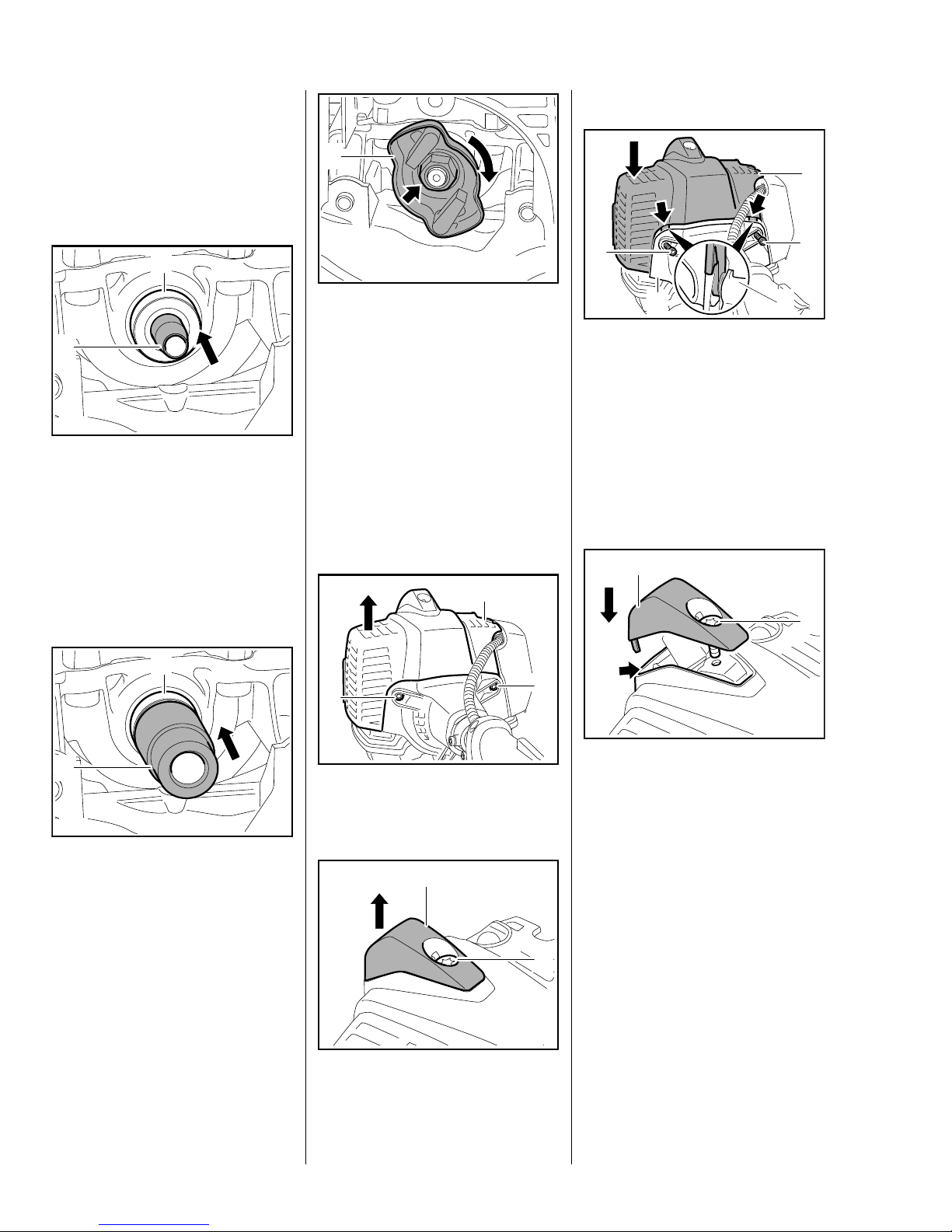
: Take out the screw (1) and
remove the fan housing (2)
– the two upper screws have
already been removed.
3
1
2
: Place the fan housing (1) on
ring (2) 5910 893 7008 – this
ensures the fan housing (1) is
upright and securely supported.
: Position the ring (2) so that it
engages the projecting clutch
drum.
: Use suitable press arbor (3) to
remove the clutch drum.
7022RA000 TG0208RA001 TG
Installing
1
0208RA002 TG
2
– Heat inner race of ball bearing to
about 120°C (250°F).
: Position clutch drum (1) on ball
bearing (2) and push it home as
far as stop.
This operation must be carried out
quickly because the clutch drum
absorbs heat and begins to expand.
1
0208RA003 TG
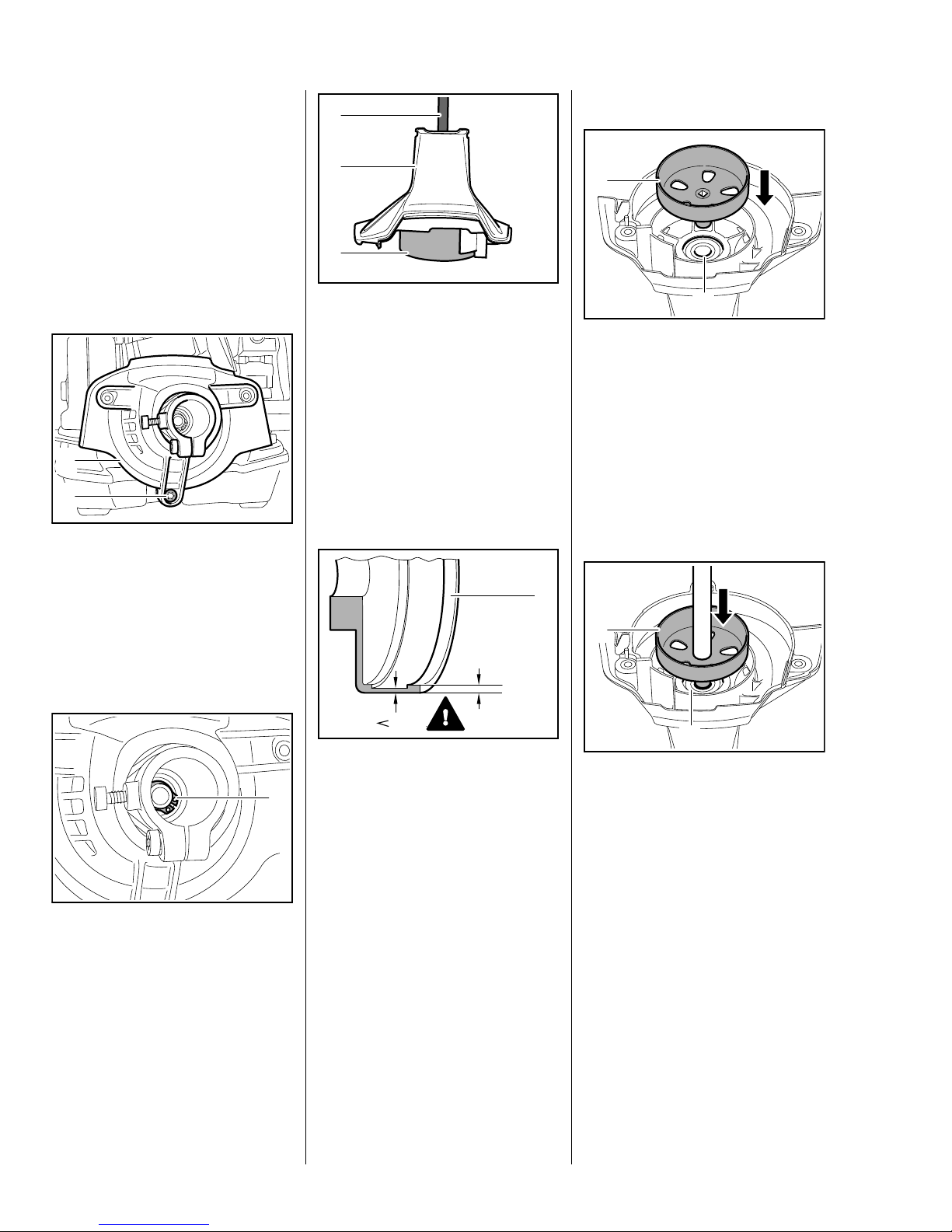
– Remove the sleeve and rubber
element, b 8.1
1
: Remove the retaining ring (1).
100%
80%
– Inspect the clutch drum (1) for
signs of wear.
If there are signs of serious wear on
the inside diameter of the clutch
drum (1), check the remaining wall
thickness. If it is less than about
80% of the original thickness, install
a new clutch drum.
If square socket is worn or the stub
damage, install a new clutch drum.
– Inspect the ball bearing and
replace if necessary.
1
0208RA396 TG
If it is not possible the heat the inner
bearing race, use a bench press to
install the cold clutch drum.
– Support the other side of the fan
housing with a suitable tube on
the inner race of the ball bearing.
: Position clutch drum (1) on ball
bearing (2) and press it home as
far as stop.
2
0208RA004 TG
16 Series 4149 Powerhead
– Install the drive tube, b 9.1
4.2 Clutch
1
: Install circlip (1) at the other side.
– Remove the sleeve and rubber
element, b 8.1
3
1
4
2
4
– Fit the shroud, b 5.4
1
0208RA001 TG
2
: Fit screws (1), then tighten down
screw (2) and screws (1) firmly.
– Install the rewind starter, b 7.2
7022RA001 TG
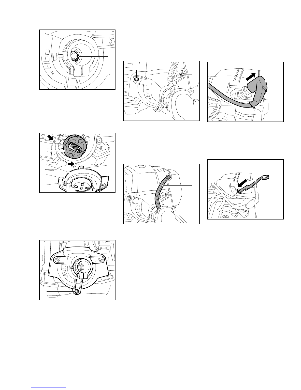
– Remove the fan housing, b 4.1
1
0208RA007 TG
: Pull boot (1) off the spark plug.
– Unscrew the spark plug.
1
1
7022RA066 TG
1
: Fit the fan housing (1) with clutch
drum (2) over the clutch (3) and
line it up so that the pins (4)
engage the holes (arrows) in the
crankcase.
1
: Tighten the screw (1) until the fan
housing is seated
– the upper screws are not fitted
and secured until the shroud is
installed – do not finally tighten
screw (1) yet.
: The throttle cable (1) must not be
under tension.
7022RA002 TG
7022RA067 TG
0208RA008 TG
: Insert locking strip (1)
0000 893 5904 in the cylinder.
17Series 4149 Powerhead
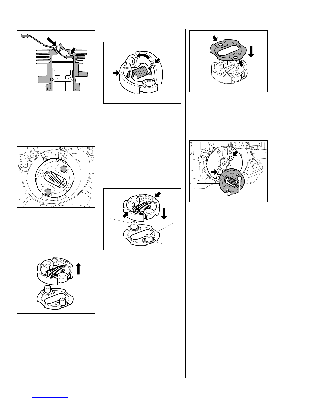
Assembling
1
1
1
1
0208RA017 TG
0208RA013 TG
: The locking strip (1)
0000 893 5904 must butt against
the cylinder wall (arrow)
– as shown in the illustration.
Disassembling
1
2
1
: Take out the screws (1).
: Remove the clutch (2) with cover
washers.
1
2
: Fold the clutch shoes (1) and
unhook the spring (2).
Position the clutch shoes (1) so that
the markings (arrows) are visible.
The spring (2) must be hooked into
the back of the clutch shoes (1).
– Reassemble the clutch shoes in
the reverse sequence.
0208RA009 TG
2
3
1
4
: Fit the washers (1) over the
sleeves.
: Position the clutch (2) so that the
marks (arrows) face up.
: Push clutch (2) onto sleeves (3)
of lower cover washer (4).
: Fit upper cover washer (1) so that
0208RA011 TG
the recesses (arrows) face up
and the holes are in alignment.
Installing
2
1
3
: Position clutch (1) with cover
washers on tapped holes
3
1
(arrows) in flywheel (2).
: Insert and tighten down the
screws (3) firmly.
0208RA012 TG
– Remove the locking strip from the
cylinder.
– Install the fan housing, b 4.1
– Reassemble all other parts in the
reverse sequence.
3
7022RA003 TG
0208RA010 TG
– Remove the upper cover washer.
: Pull the clutch (1) off the lower
cover washer.
18 Series 4149 Powerhead
5. Engine
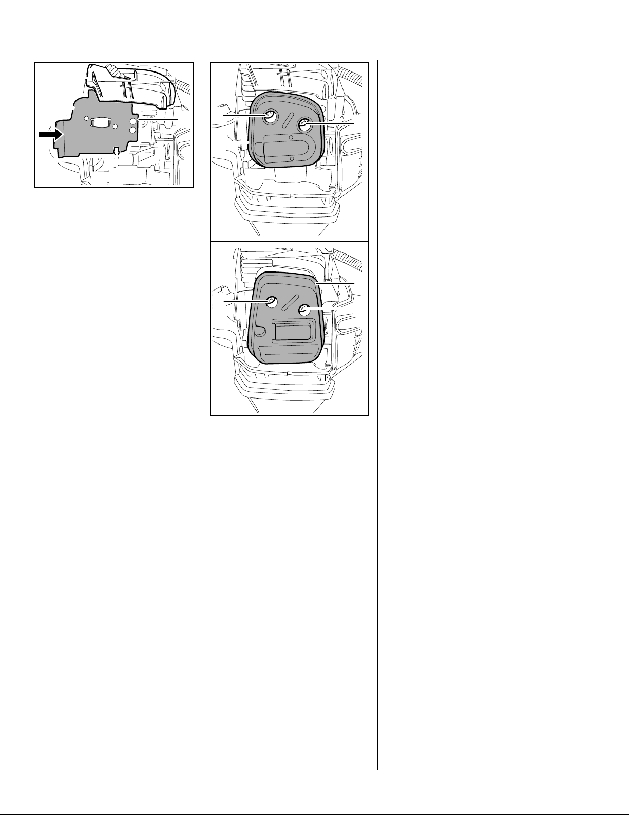
5.1 Muffler / Spark Arresting
Screen
Always check and, if necessary,
repair the fuel system, carburetor,
air filter and ignition system before
looking for faults on the engine.
– Troubleshooting, b 3
– Remove the shroud, b 5.4
Before removing the muffler, set the
piston to top dead center to ensure
that no dirt falls into the cylinder.
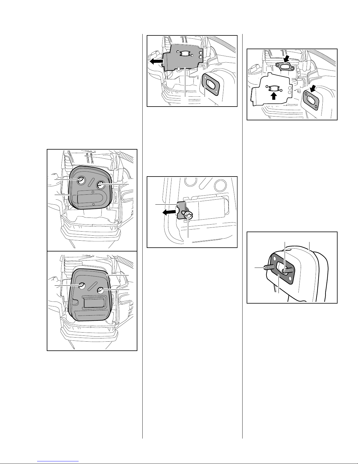
1
1
2
12
: Remove the muffler gasket (1)
and pull out the heat shield (2)
sideways – always install a new
muffler gasket.
Spark arresting screen
(if fitted)
2
Installing
7022RA005 TG
7022RA006 TG
– Cover the exhaust port. Remove
any dirt from around the cylinder
and exhaust port.
: Check and clean the sealing
faces (arrows) on the exhaust
port, heat shield and muffler,
remove any gasket residue –
make sure there is no gasket
residue or dirt in the exhaust port.
Always replace components with
damaged sealing faces.
2
1
: Take out the screws (1).
: Remove the muffler (2), check it
and replace if necessary.
1
1
: Take out the screw (1) and pull
out the spark arresting
screen (2).
– Clean the spark arresting screen
or replace if necessary.
– Reassemble in the reverse
sequence.
7022RA004 TG
1
7022RA073 TG
3
1
2
: Insert the screws (1).
: Fit new muffler gasket (2) over
the screws (1) and against the
muffler (3).
7022RA007 TG
19Series 4149 Powerhead
5.2 Leakage Test
3
Defective oil seals and gaskets or
1
2
2
1
cracks in castings are the usual
causes of leaks. Such faults allow
2
supplementary air to enter the
engine and upset the fuel-air
mixture.
4
: Push the upper edge of the heat
shield (1), tab (2) first, between
the wall of the air guide
shroud (3) and cylinder and its
lower edge between the hook (4)
and the cylinder.
: Push the heat shield (1) home
until its holes line up with the
holes in the cylinder.
7022RA007 TG
2
: Carefully fit the muffler (1) in
position and insert the screws (2)
– do not tighten down yet.
This makes adjustment of the
prescribed idle speed difficult, if not
impossible.
Moreover, the transition from idle
speed to part or full throttle is not
smooth.
Always perform the vacuum test
first and then the pressure test.
1
The engine can be checked
2
thoroughly for leaks under vacuum
and pressure with the pump
0000 850 1300.
7022RA009 TG
: Check that gasket and heat
shield are properly positioned.
: Insert and tighten down the
screws (2) firmly.
– Reassemble all other parts in the
reverse sequence.
20 Series 4149 Powerhead
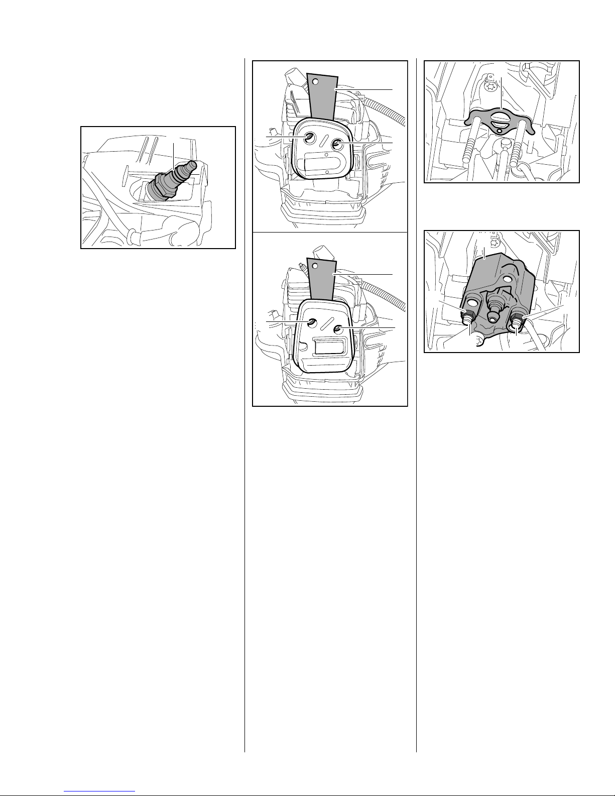
5.2.1 Preparations
1
– Remove the shroud, b 5.4
1
– Pull off the boot and unscrew the
spark plug.
– Set the piston to top dead center.
This can be checked through the
spark plug hole.
: Fit the spark plug (1) and tighten
it down firmly.
– Remove the heat shield and
gasket, fit muffler in position and
insert screws, b 5.1
2
7022RA010 TG
2
: Fit the sealing plate (1)
0000 855 8106 between the
cylinder exhaust port and muffler.
1
2
Make sure the gasket (1) is in place.
1
1
3
2
2
: Line up the flange (1)
5910 850 4200 and fit it over the
studs (2).
7022RA011 TG
: Fit the nuts (3) and tighten them
down firmly.
2
0208RA028 TG
3
7022RA218 TG
: Tighten the screws (2)
moderately.
The sealing plate must completely
fill the space between the two
screws.
– Remove carburetor with fuel
hoses still attached and put it to
one side, b 10.3
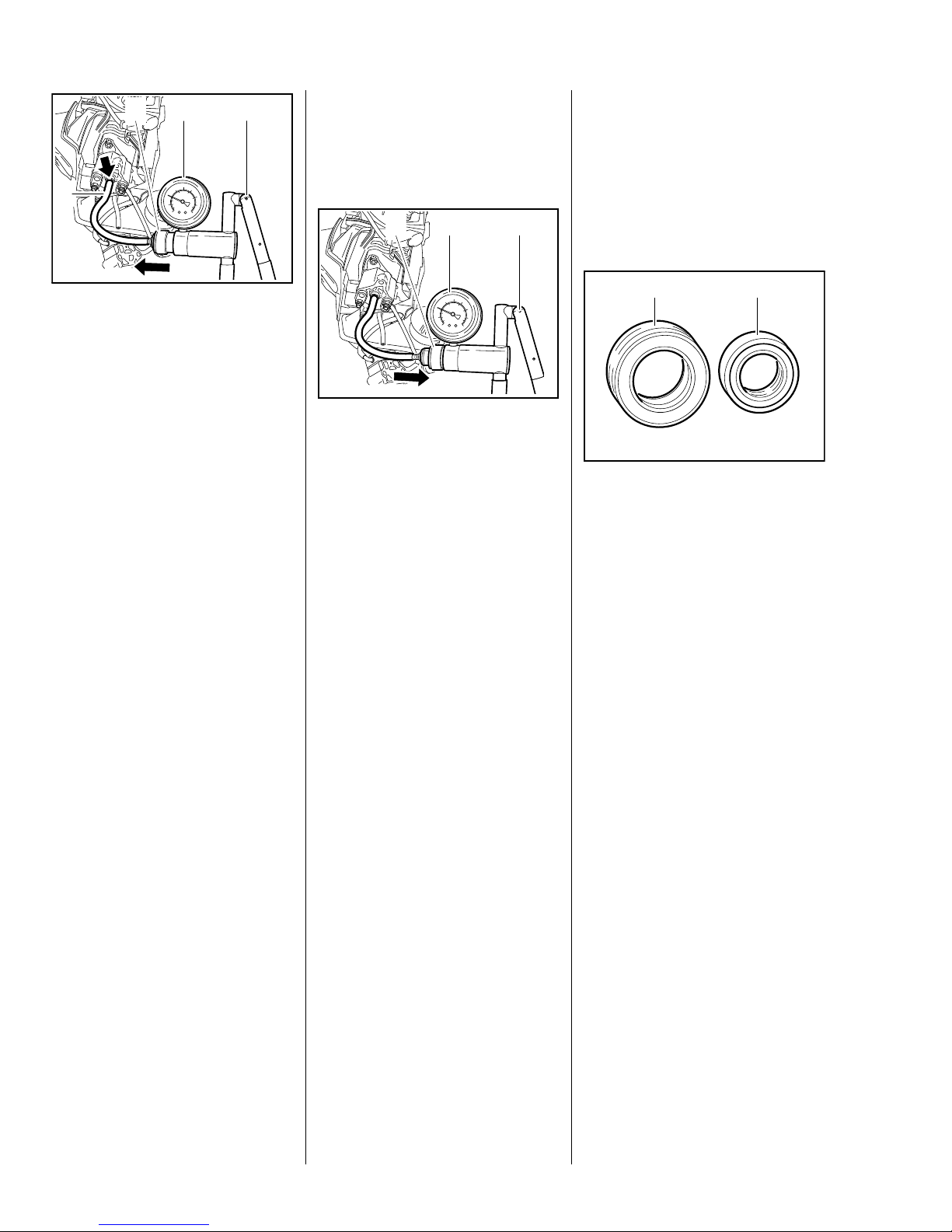
5.2.2 Vacuum Test
Oil seals tend to fail when subjected
to a vacuum, i.e. the sealing lip lifts
away from the crankshaft during the
piston's induction stroke because
there is no internal counterpressure.
A test can be carried out with pump
0000 850 1300 to detect this kind of
fault.
21Series 4149 Powerhead
2
4
3
5.2.3 Pressure Test
– Install the gasket, heat shield and
muffler, b 5.1
Carry out the same preparations as
for the vacuum test, b 5.2.2
– Reassemble all other parts in the
reverse sequence.
1
: Connect hose (1) of pump
0000 850 1300 to the nipple
(arrow).
: Push ring (2) to the left
– vacuum test.
: Operate the lever (3) until the
pressure gauge (4) indicates a
vacuum of 0.5 bar.
If the vacuum reading remains
constant, or rises to no more than
0.3 bar within 20 seconds, it can be
assumed that the oil seals are in
good condition.
If the pressure continues to rise
(reduced vacuum in engine), the oil
seals must be replaced, b 5.3.
31
7022RA220 TG
: Push ring (1) to the right
– pressure test.
: Operate the lever (2) until the
pressure gauge (3) indicates a
pressure of 0.5 bar. If this
pressure remains constant for at
least 20 seconds, the engine is
airtight.
– If the pressure drops, the leak
must be located and the faulty
part replaced.
2
5.3 Oil Seals
1 2
7022RA219 TG
5904RA044 TG
When replacing oil seals, note that
the 12x22x5 oil seal (1) must be
installed at the ignition side and the
10x20x4 oil seal (2) at the starter
side.
It is not necessary to disassemble
the engine to replace the oil seals.
– After finishing the test, push the
ring to the right to vent the pump.
– Continue with pressure test,
b 5.2.3
To find the leak, coat the suspect
area with soapy water and
pressurize the engine again.
Bubbles will appear if a leak exists.
– After finishing the test, push the
ring to the left to vent the pump –
disconnect the hose.
– Remove the flange
5910 850 4200 from the intake
manifold.
– Install the carburetor, b 10.3
– Remove the muffler and the
sealing plate 0000 855 8106.
22 Series 4149 Powerhead
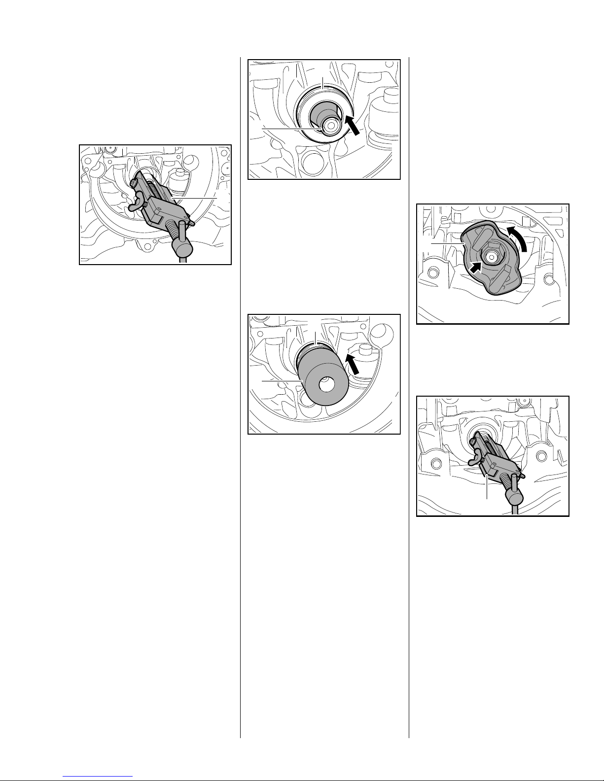
Ignition Side
– Remove the clutch, b 4.2
2
reverse sequence.
– Reassemble all other parts in the
– Remove the flywheel, b 6.5
1
Take care not to damage the
crankshaft stub.
– Free off the oil seal in its seat by
tapping it with a suitable tube or a
punch.
: Apply puller (1) 5910 890 4400
with No. 6 jaws 0000 893 3711.
1
: Fit the installing sleeve (1)
4149 893 4600.
: Slip the oil seal (2), sealing lip
facing the crankcase, over the
installing sleeve.
0208RA018 TG
– Remove the installing sleeve.
2
1
Starter Side
– Remove the rewind starter,
b 7.2
– Block the piston, b 4.2
0208RA141 TG
1
: Use hexagon (arrow) to loosen
and unscrew carrier (1)
counterclockwise.
0208RA073 TG
– Clamp the puller arms.
– Pull out the oil seal.
Installing
– Clean the sealing face, b 12
– Lubricate sealing lips of new oil
seal with grease, b 12
To avoid the risk of engine damage,
only use press sleeve (1)
4149 893 2400 to install the oil seal.
: Fit the press sleeve (1)
4149 893 2400 with the smaller
diameter (22 mm) facing the
crankcase and press home the oil
seal (2).
The seating face must be flat and
free from burrs.
– Degrease the crankshaft taper,
b 12
0208RA142 TG
1
Take care not to damage the
crankshaft stub.
– Free off the oil seal in its seat by
tapping it with a suitable tube or a
punch.
: Apply puller (1) 5910 890 4400
with No. 3.1 jaws 0000 893 3706.
– Clamp the puller arms and pull
out the oil seal.
0208RA143 TG
23Series 4149 Powerhead
Installing
– Clean the sealing face.
– Lubricate sealing lips of new oil
seal with grease, b 12
Installing
1
1
2
1
: Fit the installing sleeve (1)
1146 893 4600.
: Slip the oil seal (2), sealing lip
facing the crankcase, over the
installing sleeve.
– Remove the installing sleeve.
2
: Use hexagon (arrow) to screw
carrier (1) into place clockwise,
then tighten it down firmly.
– Reassemble all other parts in the
reverse sequence.
0208RA144 TG
5.4 Shroud
– Remove the rewind starter,
b 7.2
2
1
4
0208RA146 TG
3 2
: Fit the shroud (1) so that the tabs
(arrows) engage between the
crankcase (2) and fan
housing (3).
: Insert and tighten down the
screws (4) firmly.
– Install the rewind starter, b 7.2
1
1
4
0208RA034 TG
2
1
: Fit the press sleeve (1)
4149 893 2400 with the larger
diameter (25 mm) facing the
crankcase and press home the oil
seal (2).
The seating face must be flat and
free from burrs.
: Take out the screws (1) and
remove the shroud (2).
0208RA145 TG
2
: Take out the screw (1) and
remove the cover (2).
0208RA032 TG0208RA033 TG
: Push tab of cover (1) into
opening in shroud and fit cover in
position.
: Insert and tighten down the
screw (2) firmly.
1
0208RA035 TG
24 Series 4149 Powerhead
5.4.1 Air guide shroud
– Remove the drive tube, b 9.1
1
so that the lug (2) points towards
the carburetor.
: Line up the manual fuel pump (1)
– Remove the shroud, b 5.4
– Remove the fan housing, b 4.1
– Remove the ignition module,
b 6.2
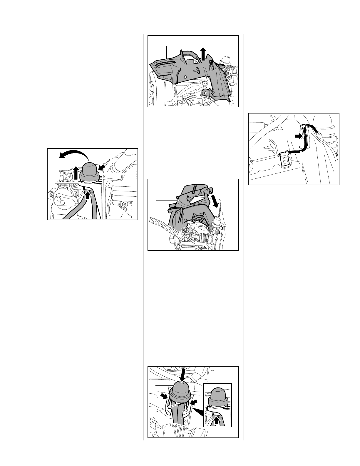
– Pull short circuit wire out of guide
in air guide shroud.
2
1
: Squeeze locking tabs (arrows)
under the retainer (1) together
and push out the manual fuel
pump (2).
: Remove the manual fuel
pump (2) with fuel hoses still
attached and put it to one side.
– Unscrew the spark plug.
: Lift the air guide shroud (1) at the
starter side and remove it over
the cylinder.
Installing
1
0208RA054 TG
: Position the air guide shroud (1)
at a slight angle and lower it in the
direction of the starter side.
: Push the manual fuel pump (1)
into the retainer (3) on the air
guide shroud until the locking
tabs (arrows) snap into place
below the retainer (3).
7022RA012 TG
1
: Starting at the flag terminal, push
the short circuit wire (1) into the
guide (arrow) so that it fits snugly
– if necessary, also push the
wires on the throttle cable
retainer fully into the guide.
– Reassemble all other parts in the
7022RA013 TG
reverse sequence.
0208RA155 TG
: Line up the air guide shroud (1)
so that it locates on the cylinder
and spacer flange and lines up
with the holes in the cylinder.
– Fit the spark plug and tighten it
down firmly.
– Install the ignition module, b 6.2
1
2
3
0208RA061 TG
25Series 4149 Powerhead
5.5 Cylinder
Before removing the cylinder,
decide whether or not the
crankshaft has to be removed as
well.
Cylinder installed
To remove the clutch, flywheel or
carrier, block the.crankshaft by
inserting the locking strip in the
spark plug hole.
– Remove the ignition module and
air guide shroud, b 6.2
– Remove the muffler, b 5.1
– Remove the fuel tank, b 10.9
1
1
Versions with 0.75 kW engine
2
3
4
1
0208RA335 TG
Cylinder removed
To remove the clutch, flywheel or
carrier, block the crankshaft by
resting the piston on the wooden
assembly block.
All sealing faces must be in perfect
condition. If the sealing faces are
damaged, replace the part
concerned, b 3.6.
– Remove the rewind starter,
b 7.2
– Remove the shroud, b 5.4
– Remove the filter cover, b 10.2
– Remove the throttle cable / short
circuit wire, b 6.6.2
– Remove the drive tube, b 9.1
– Remove the fan housing, b 4.1
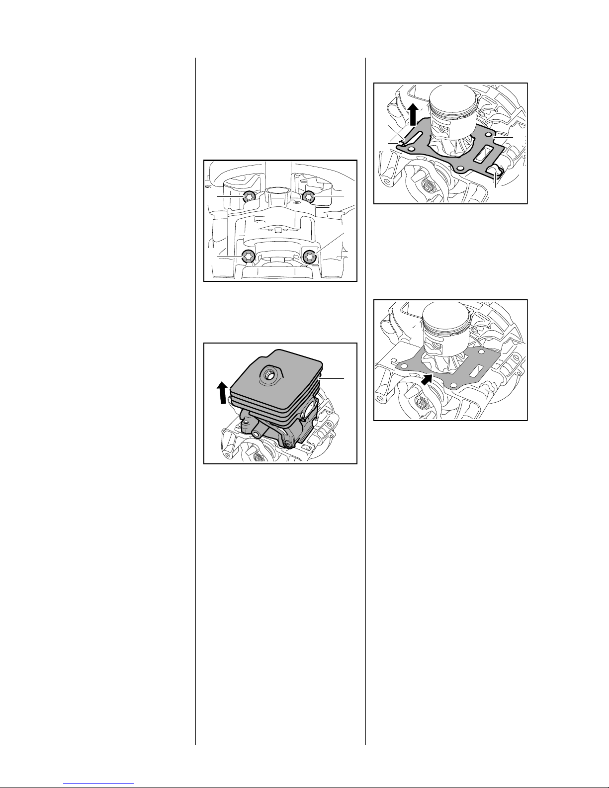
1
1
: Remove the screws (1) from the
underside of the crankcase.
1
: Carefully lift the cylinder (1)
away.
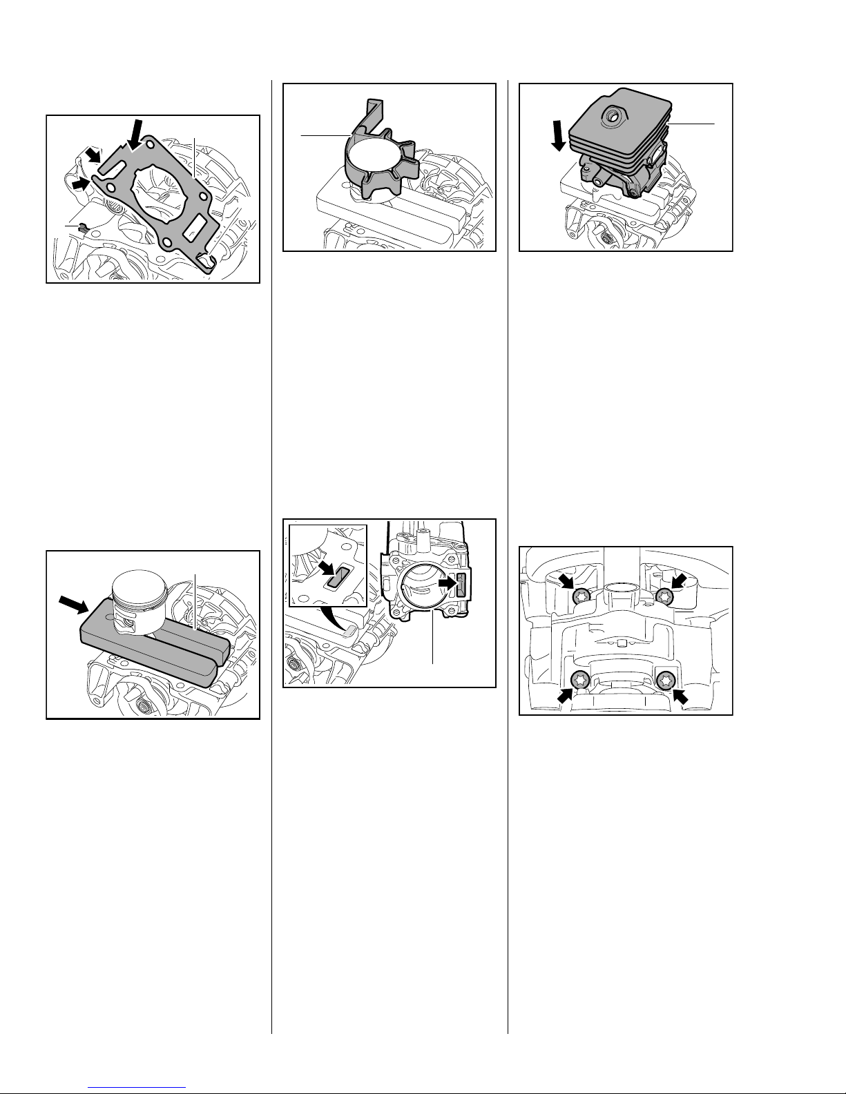
: Lift cylinder gasket (1) with
tab (2) over the lug (3), detach it
from the hook (4) and lift it over
the piston – always install a new
cylinder gasket.
0208RA108 TG
: Inspect and clean the sealing
face (arrow) – components with
0208RA109 TG
damaged sealing faces must be
replaced, b 12
0208RA337 TG
– Pull off the boot and unscrew the
spark plug, b 4.2
– Pull off the carburetor and put it to
one side – there is no need to
remover the fuel hoses, b 10.3
– Remove the spacer flange,
b 10.6
26 Series 4149 Powerhead
Versions with 0.9 kW engine
– Remove the piston, b 5.7
Versions with replaceable needle
cage
If the piston or the oil seals are
damaged, also inspect the inside of
the cylinder for signs of damage and
install a new cylinder if necessary.
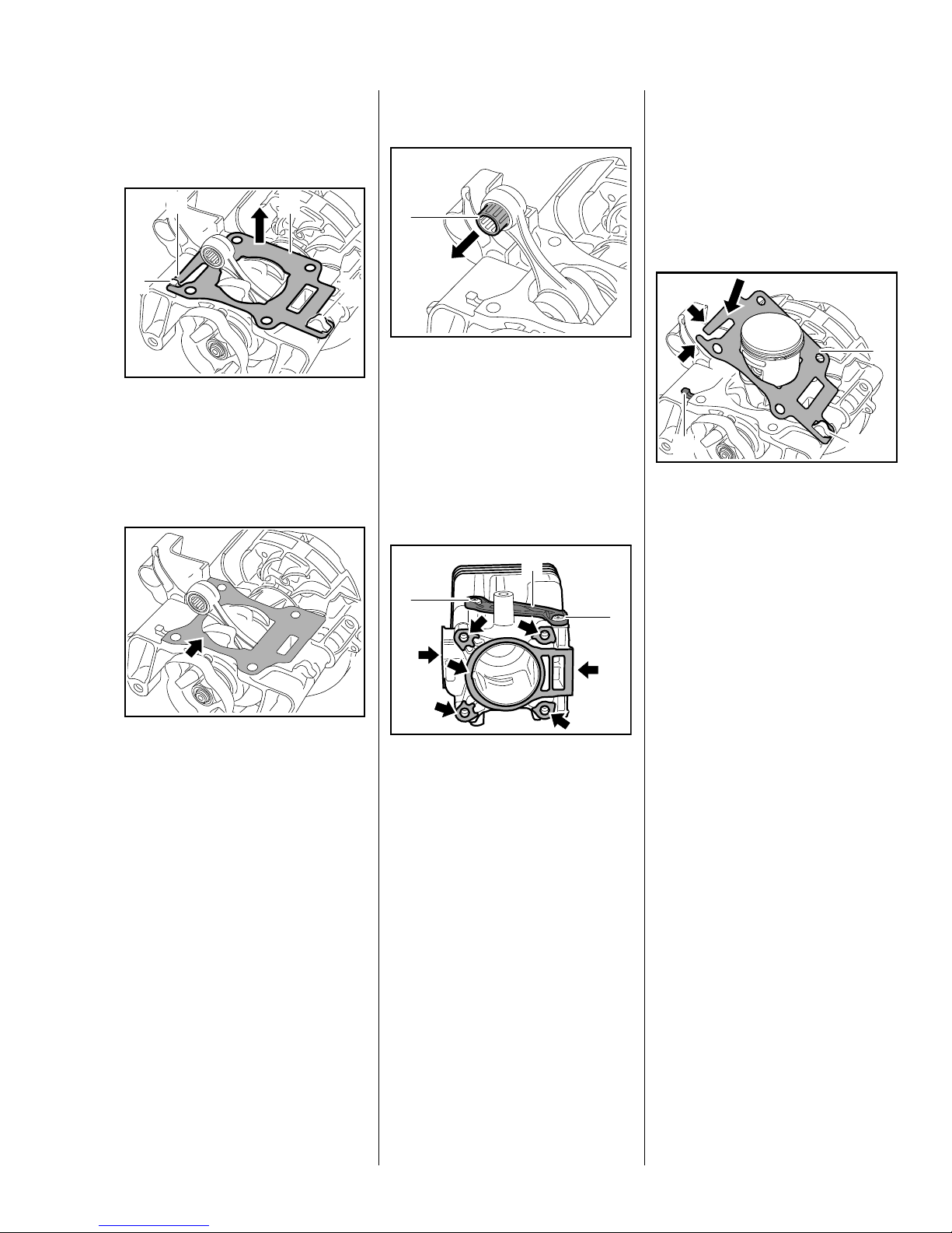
2
1
3
: Lift cylinder gasket (1) with
tab (2) over the lug (3), detach it
from the hook (4) and lift it over
the connecting rod – always
install a new cylinder gasket.
1
4
: Pull out the needle cage (1),
0208RA110 TG
inspect and clean it, replace if
necessary.
– Reassemble in the reverse
sequence.
All models
1
Installing
Versions with 0.75 kW engine
0208RA112 TG
1
3
: Fit the new cylinder gasket (1)
over the piston, attach it to the
hook (2) and place it in position.
2
: Press down tabs (arrows) of new
cylinder gasket (1) until they
locate behind the lug (3).
1
– the cylinder gasket is now held
in position.
2
0208RA338 TG
: Inspect and clean the sealing
face (arrow) – components with
damaged sealing faces must be
replaced, b 12
Versions with fixed needle cage
The needle cage is permanently
connected to the small end and
cannot be replaced separately.
– Inspect and clean the needle
cage, replace crankshaft if
necessary, b 5.6
0208RA111 TG
0208RA113 TG
The screws (1) and cover (2) must
not be removed at either side.
: Inspect and clean the sealing
faces (arrows) and remove any
gasket residue, b 12
Always use a new cylinder gasket
when re-installing the cylinder.
– Inspect the piston and piston
rings and replace if necessary,
b 5.7, b 5.8
27Series 4149 Powerhead
Versions with 0.9 kW engine
0208RA119 TG
1
2
3
: Fit the new cylinder gasket (1)
over the piston, attach it to the
hook (2) and place it in position.
: Press down tabs (arrows) of new
cylinder gasket (1) until they
locate behind the lug (3).
– the cylinder gasket is now held
in position.
– Install the piston, b 5.7
All models
1
– Lubricate the piston, piston rings
0208RA114 TG
and cylinder wall with oil, b 12
– Check correct installed position
of rings, b 5.8
: Use the clamping strap (1)
0000 893 2600 to compress the
rings around the piston.
Apply the clamping strap (1) so that
the piston rings do not project
beyond the cylinder wall.
0208RA116 TG
While sliding the cylinder over the
piston, hold the clamping strap
tightly around the piston so that the
rings do not project
– they might otherwise break.
: Slide the cylinder (1) over the
piston, the clamping strap moves
downwards at the same time.
– Remove the clamping strap and
wooden assembly block.
Make sure the cylinder gasket is
properly seated.
1
0208RA118 TG
1
: Slide the wooden assembly
block (1) 1108 893 4800
between the piston and
crankcase.
Take care not to damage the
cylinder gasket.
: Position the cylinder (1) so that
0208RA115 TG
the rectangular ports (arrows) are
in alignment.
1
0208RA117 TG
– Push cylinder on as far as stop
and hold it steady, then turn
cylinder and crankcase over.
: Fit screws (arrows) in underside
of crankcase and tighten them
down firmly in crosswise pattern.
– Reassemble all other parts in the
reverse sequence.
28 Series 4149 Powerhead
 Loading...