


{
STIHL KM 85 R
Instruction Manual


Contents
English
KombiSystem 2
Guide to Using this Manual 2
Safety Precautions and Working
Techniques 2
Approved KombiTools 7
Mounting the Loop Handle 8
Adjusting the Throttle Cable 9
Fuel 9
Original Instruction ManualPrinted on chlorine-free paper
Fueling 10
Starting / Stopping the Engine 11
Operating Instructions 13
Cleaning the Air Filter 13
Adjusting the Carburetor 14
Spark Arresting Screen in Muffler 15
Spark Plug 16
Replacing the Starter Rope and
Rewind Spring 17
Storing the Machine 19
Maintenance and Care 20
Minimize Wear and Avoid Damage 21
Main Parts 22
Specifications 23
Printing inks contain vegetable oils, paper can be recycled.
Special Accessories 24
Maintenance and Repairs 24
EC Declaration of Conformity 24
Quality Certification 25
Dear Customer,
Thank you for choosing a quality
engineered STIHL product.
This machine has been built using
modern production techniques and
comprehensive quality assurance.
Every effort has been made to ensure
your satisfaction and troublefree use of
the machine.
Please contact your dealer or our sales
company if you have any queries
concerning your machine.
Your
Hans Peter Stihl
{
© ANDREAS STIHL AG & Co. KG, 2012
0458-462-0121. VA2.D12.
0000000442_005_GB
KM 85 R
This instruction manual is protected by copyright. All rights reserved, especially the rights to reproduce, translate and process
with electronic systems.
1

English
.
.
.
.
002BA442 KN
+
+
KombiSystem
In the STIHL KombiSystem a number of
different KombiEngines and KombiTools
can be combined to produce a power
tool. In this instruction manual the
functional unit formed by the
KombiEngine and KombiTools is
referred to as the power tool.
Therefore, the separate instruction
manuals for the KombiEngine and
KombiTool should be used together for
the power tool.
Always read and and make sure you
understand both instruction manuals
before using your power tool for the first
time and keep them in a safe place for
future reference.
Guide to Using this Manual Safety Precautions and
Working Techniques
Pictograms
All the pictograms attached to the
machine are shown and explained in this
manual.
Symbols in text
Warning where there is a risk of an
accident or personal injury or serious
damage to property.
Caution where there is a risk of
damaging the machine or its individual
components.
Engineering improvements
STIHL's philosophy is to continually
improve all of its products. For this
reason we may modify the design,
engineering and appearance of our
products periodically.
Therefore, some changes, modifications
and improvements may not be covered
in this manual.
Observe all application local safety
regulations, standards and ordinances.
If you have not used this type of power
tool before: Have your dealer or other
experienced user show you how to
operate your power tool or attend a
special course in its operation.
Minors should never be allowed to use a
power tool.
Keep bystanders, especially children,
and animals away from the work area.
When the power tool is not in use, shut it
off so that it does not endanger others.
Secure it against unauthorized use.
The user is responsible for avoiding
injury to third parties or damage to their
property.
Special safety precau
tions must be observed
when working with a
power tool.
Always read and and
make sure you under
stand both instruction
manuals (KombiEngine
and KombiTool) before
using your power tool for
the first time and keep
them in a safe place for
future reference. Nonobservance of the safety
precautions may result in
serious or even fatal
injury.
-
-
2
KM 85 R

English
Lend or rent your machine only to
persons who are familiar with this model
and its operation – do not lend of rent
your machine without the KombiEngine
and KombiTool instruction manuals.
The use of noise emitting power tools
may be restricted to certain times by
national or local regulations.
To operate the power tool you must be
rested, in good physical condition and
mental health.
If you have any condition that might be
aggravated by strenuous work, check
with your doctor before operating a
power tool.
Persons with pacemakers only: The
ignition system of your power tool
produces an electromagnetic field of a
very low intensity. This field may
interfere with some pacemakers. STIHL
recommends that persons with
pacemakers consult their physician and
the pacemaker manufacturer to reduce
any health risk.
Do not operate the power tool if you are
under the influence of any substance
(drugs, alcohol) which might impair
vision, dexterity or judgment.
Use your power tool only for the
applications described in the instruction
manual of the KombiTool you are using.
Do not use your power tool for any other
purpose because of the increased risk of
accidents.
Do not operate the KombiEngine without
a properly mounted KombiTool since
this may result in damage to the
machine.
Only use KombiTools and accessories
that are explicity approved for this power
tool by STIHL or are technically
identical. It is important that you read the
chapter on "Approved KombiTools". If
you have any questions in this respect,
consult a servicing dealer. Use only high
quality parts and accessories in order to
avoid the risk of accidents and damage
to the machine.
STIHL recommends the use of original
STIHL replacement parts. They are
specifically designed to match your
model and meet your performance
requirements.
Never attempt to modify your power tool
in any way since this may increase the
risk of personal injury. STIHL excludes
all liability for personal injury and
damage to property caused while using
unauthorized attachments.
Do not use a pressure washer to clean
your power tool. The solid jet of water
may damage parts of the power tool.
Clothing and Equipment
Wear proper protective clothing and
equipment.
Avoid clothing that could
get caught on branches
or brush or moving parts
of the machine. Do not
wear a scarf, necktie or
jewelry. Tie up and con
fine long hair (e.g. with a
hair net, cap, hard hat,
etc.).
See also notes on "Clothing and
Equipment" in the instruction manual of
the KombiTool you are using.
-
Transporting the Power Tool
Always turn off the engine.
Transporting in a vehicle: Properly
secure your power tool to prevent
turnover, fuel spillage and damage.
See also notes on "Transporting the
Machine" in the instruction manual of the
KombiTool you are using.
Fueling
Gasoline is an extremely
flammable fuel. Keep
clear of naked flames. Do
not spill any fuel – do not
smoke.
Always shut off the engine before
refueling.
Do not fuel a hot engine – fuel may spill
and cause a fire.
Open the fuel cap carefully to allow any
pressure build-up in the tank to release
slowly and avoid fuel spillage.
Fuel your power tool only in wellventilated areas. If you spill fuel, wipe
the machine immediately – if fuel gets on
your clothing, change immediately.
KM 85 R
3

English
002BA273 KN
Your power tool comes standard with
either a screw-type or bayonet-type fuel
cap. After fueling,
tighten down the screwtype fuel cap as securely
as possible.
Insert the fuel cap with
hinged grip (bayonet-type
cap) correctly in the
opening, turn it clockwise
as far as stop and fold the
grip down.
This reduces the risk of unit vibrations
causing the fuel cap to loosen or come
off and spill quantities of fuel.
To reduce the risk of serious or fatal
burn injuries, check for fuel leakage. If
fuel leakage is found, do not start or run
the engine until leak is fixed.
Before Starting
Check that your power tool is properly
assembled and in good condition – refer
to appropriate chapters in the instruction
manuals.
– Use only an approved combination
of cutting attachment, deflector,
handle and harness. All parts must
be assembled properly and
securely.
– Slide control / stop switch must
move easily to STOP or 0
– Smooth action of throttle trigger
lockout and throttle trigger – the
throttle trigger must return
automatically to the idle position.
– Check that the spark plug boot is
secure – a loose boot may cause
arcing that could ignite combustible
fumes and cause a fire.
– Never attempt to modify the controls
or safety devices in any way.
– Keep the handles dry and clean –
free from oil and dirt – for safe
control of the power tool.
– Adjust harness and handle to suit
your height and reach.
To reduce the risk of personal injury, do
not operate your power tool if it is
damaged or not properly assembled.
If you use a shoulder strap or full
harness: Practice removing and putting
down the machine as you would in an
emergency. To avoid damage, do not
throw the machine to the ground when
practicing.
See also notes on "Before Starting" in
the instruction manual of the KombiTool
you are using.
Starting the Engine
Start the engine at least 3 meters from
the fueling spot, outdoors only.
Place the unit on firm ground in an open
area. Make sure you have good balance
and secure footing. Hold the unit
securely. The working tool must be clear
of the ground and all other obstructions
because it may begin to run when the
engine starts.
To reduce the risk of injury, avoid
contact with the attachment.
Do not drop start the power tool – start
the engine as described in the
instruction manual. Note that the
attachment continues to run for a short
period after you let go of the throttle
trigger – flywheel effect.
Check idle speed setting: The
attachment must be stationary when the
engine is idling with the throttle trigger
released.
To reduce the risk of fire, keep hot
exhaust gases and hot muffler away
from easily combustible materials (e.g.
wood chips, bark, dry grass, fuel).
See also notes on "Starting / Stopping
the Engine" in the instruction manual of
the KombiTool you are using.
Holding and Controlling the Power Tool
Always hold the power tool firmly with
both hands on the handles.
Make sure you always have good
balance and secure footing.
Left hand on loop handle, right hand on
control handle, even if you are lefthanded.
4
KM 85 R

English
During Operation
In the event of impending danger or in
an emergency, switch off the engine
immediately by moving the slide control
/ stop switch to STOP or 0.
The correct engine idle speed is
important to ensure that the attachment
stops moving when you let go of the
throttle trigger. If the working tool
continues to move when the engine is
idling, have your dealer check the
machine and make proper adjustments
or repairs. Check and correct the idle
speed setting at regular intervals. STIHL
recommends you have this work done
by a STIHL servicing dealer.
Be particularly alert and cautious when
wearing hearing protection because
your ability to hear warnings (shouts,
alarms, etc.) is restricted.
To reduce the risk of accidents, take a
break in good time to avoid tiredness or
exhaustion.
Work calmly and carefully – in daylight
conditions and only when visibility is
good. Stay alert so as not to endanger
others.
Use your power tool only for those
applications described in the KombiTool
instruction manual.
Your power tool produces
toxic exhaust fumes as
soon as the engine is
running. These fumes
may be colorless and
odorless and contain
unburned hydrocarbons
and benzol. Never run
the engine indoors or in
poorly ventilated loca
tions, even if your model
is equipped with a cata
lytic converter.
To reduce the risk of serious or fatal
injury from breathing toxic fumes,
ensure proper ventilation when working
in trenches, hollows or other confined
locations.
To reduce the risk of accidents, stop
work immediately in the event of
nausea, headache, visual disturbances
(e.g. reduced field of vision), problems
with hearing, dizziness, deterioration in
ability to concentrate. Apart from other
possibilities, these symptoms may be
caused by an excessively high
concentration of exhaust gases in the
work area.
Operate your power tool so that it
produces a minimum of noise and
emissions – do not run the engine
unnecessarily, accelerate the engine
only when working.
To reduce the risk of fire, do not smoke
while operating or standing near your
power tool. Note that combustible fuel
vapor may escape from the fuel system.
The dusts, vapor and smoke produced
during operation may be dangerous to
health. Wear a suitable respirator in very
dusty or smoky conditions.
-
-
If your power tool is subjected to
unusually high loads for which it was not
designed (e.g. heavy impact or a fall),
always check that it is in good condition
before continuing work – see also
"Before Starting". Check the fuel system
in particular for leaks and make sure the
safety devices are working properly. Do
not continue operating your power tool if
it is damaged. In case of doubt, have the
unit checked by your servicing dealer.
Do not operate your power tool in the
starting throttle position – engine speed
cannot be controlled in this position.
Before leaving the power tool
unattended: Shut off the engine.
To reduce the risk of injury, always shut
off the engine before changing the
KombiTool or working tool.
Vibrations
Prolonged use of the power tool may
result in vibration-induced circulation
problems in the hands (whitefinger
disease).
No general recommendation can be
given for the length of usage because it
depends on several factors.
The period of usage is prolonged by:
– Hand protection (wearing warm
gloves)
– Work breaks
KM 85 R
5

English
The period of usage is shortened by:
– Any personal tendency to suffer
from poor circulation (symptoms:
frequently cold fingers, tingling
sensations).
– Low outside temperatures.
– The force with which the handles
are held (a tight grip restricts
circulation).
Continual and regular users should
monitor closely the condition of their
hands and fingers. If any of the above
symptoms appear (e.g. tingling
sensation in fingers), seek medical
advice.
Maintenance and Repairs
Service the machine regularly. Do not
attempt any maintenance or repair work
not described in the instruction manual.
Have all other work performed by a
servicing dealer.
STIHL recommends that you have
servicing and repair work carried out
exclusively by an authorized STIHL
servicing dealer. STIHL dealers are
regularly given the opportunity to attend
training courses and are supplied with
the necessary technical information.
Only use high-quality replacement parts
in order to avoid the risk of accidents
and damage to the machine. If you have
any questions in this respect, consult a
servicing dealer.
STIHL recommends the use of original
STIHL replacement parts. They are
specifically designed to match your
model and meet your performance
requirements.
To reduce the risk of injury, always shut
off the engine before carrying out any
maintenance or repairs or cleaning the
machine. – Exception: Carburetor and
idle speed adjustments.
Do not turn the engine over on the
starter with the spark plug boot or spark
plug removed unless the slide control /
stop switch is on STOP or 0 since there
is otherwise a risk of fire from
uncontained sparking.
To reduce the risk of fire, do not service
or store your machine near open flames.
Check the fuel filler cap for leaks at
regular intervals.
Use only a spark plug of the type
approved by STIHL and make sure it is
in good condition – see "Specifications".
Inspect the ignition lead (insulation in
good condition, secure connection).
Check the condition of the muffler.
To reduce the risk of fire and damage to
hearing, do not operate your machine if
the muffler is damaged or missing. –
Do not touch a hot muffler since burn
injury will result.
Vibration behavior is influenced by the
condition of the AV elements – check the
AV elements at regular intervals.
6
KM 85 R

Approved KombiTools
BF-KM
470BA017 KN
FCS-KM
FCB-KM
KW-KM
KB-KM
FH-KM
BG-KM
SP-KM
FS-KM
FS-KM
FSB-KM
HT-KM
English
The following STIHL KombiTools may
be mounted on the KombiEngine:
KombiTool Purpose
FS-KM Brushcutter with
mowing head
FS-KM Brushcutter with
grass cutting blade
FSB-KM Brushcutter with
mowing head
HL-KM 135° Hedge trimmer,
adjustable
HL-KM 0° Hedge trimmer
FH-KM 135° Power scythe
BG-KM Blower
HT-KM Pole pruner
BF-KM Cultivator
FCB-KM Power edger
FCS-KM Power edger
SP-KM Special harvester
KB-KM Bristle brush
KW-KM PowerSweep
The barrier bar supplied with the
machine must be mounted to the loop
handle – see also "Mounting the Loop
Handle".
KM 85 R
7

English
2
002BA098 KN
1
1
5
4
002BA099 KN
2
3
6
7
A
9
8
4
002BA353 KN
Mounting the Loop Handle
A barrier bar is supplied with the
machine. Attach the barrier bar to the
loop handle.
N Insert square nuts (1) in the barrier
bar (2) – the holes must line up
8
N Insert the clamp (3) in the loop
handle (4) and position them
together on the shaft (5)
N Position clamp (6)
N Position barrier bar (2) – note
position!
N Line up the holes
N Insert bolts (7) in the holes – and
screw them into the barrier bar as
far as possible
N Fit the loop handle (4) at a distance
of (A) approx. 20 cm (8 in) forward
of the control handle (8)
N Orient the loop handle
N Tighten the bolts – lock the nuts if
necessary
The sleeve (9) is present depending on
the country and must be located
between the loop handle and control
handle.
Always leave the barrier bar attached.
KM 85 R

English
002BA163 KN
2
1
002BA161 KN
Adjusting the Throttle Cable
A properly adjusted throttle cable is the
precondition for correct operation in the
full throttle, starting throttle and idle
positions.
N Adjust the throttle cable only when
the unit is completely and properly
assembled.
N Use a suitable tool to push the slide
to the end of the slot (see
illustration).
N Press down the throttle trigger
lockout (1) and squeeze the throttle
trigger (2) (full throttle) – this sets
the throttle cable correctly.
Fuel
The engine requires a mixture of
gasoline and engine oil.
Avoid direct skin contact with and
breathing in of gasoline fumes.
STIHL MotoMix
STIHL recommends using STIHL
MotoMix. This pre-blended fuel is free of
benzene and lead, stands out because
of a high octane rating, and always
provides the proper mixing ratio.
STIHL MotoMix is blended with STIHL
HP Ultra two-stroke engine oil for
maximum engine life.
MotoMix is not available in all markets.
Mixing fuel
Unsuitable fuels or a mixing ratio that
deviates from the specification can lead
to severe engine damage. The engine,
seals, fuel lines and fuel tank may be
damaged if poor quality gasoline or
engine oil is used.
Gasoline
Use only high-quality gasoline with an
octane rating of at least 90 ROC –
leaded or unleaded.
Unleaded gasoline must be used in
machines equipped with a catalytic
converter.
Using multiple tankfuls of leaded
gasoline can substantially reduce the
effectiveness of the catalytic converter.
Gasoline with an alcohol component
exceeding 10% can cause impaired
engine performance in engines with
manually adjustable carburetors and
thus should not be used in these
engines.
Engines with M-Tronic deliver full engine
performance using gasoline with an
alcohol component of up to 25% (E25).
Engine oil
Use only high-quality two-stroke engine
oil – ideally STIHL HP, HP Super or
HP Ultra two-stroke engine oil, as they
are specially engineered for STIHL
engines. HP Ultra ensures maximum
performance and engine life.
The engine oils are not available in all
markets.
Only STIHL two-cycle engine oil 1:50
may be used to produce the fuel mixture
for machines with a catalytic converter.
Mixing ratio
for STIHL two-cycle engine oil 1:50;
1:50 = 1 part oil + 50 parts gasoline
KM 85 R
9

English
389BA031 KN
Examples
Quantity of
gasoline
Liters Liters (ml)
10.02(20)
5 0.10 (100)
10 0.20 (200)
15 0.30 (300)
20 0.40 (400)
25 0.50 (500)
N Pour oil into an approved safety fuel
canister first, then add gasoline and
mix thoroughly
Storing fuel mixture
Store in approved safety fuel canisters
only in a dry, cool and secure place
protected against light and sunlight.
Fuel mixture ages – mix only as much as
needed for a few weeks. Do not store
fuel mixture for longer than
three months. The fuel mixture can
become unusable faster if exposed to
light, sunlight or low or high
temperatures.
N Shake the canister containing the
fuel mixture thoroughly before
refueling
Pressure can build up inside the canister
– open carefully.
N The fuel tank and the canister in
which fuel mixture is stored should
be cleaned thoroughly from time to
time
STIHL two-cycle engine
oil 1:50
Residual fuel and the liquid used for
cleaning must be disposed of in
accordance with regulations and without
harming the environment!
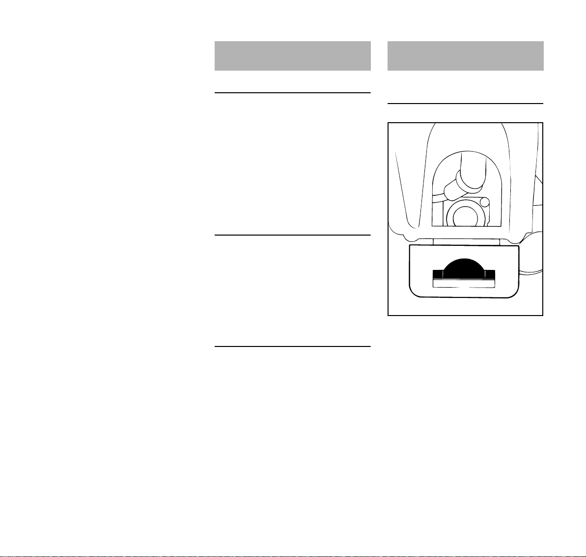
Fueling
Preparations
N Before fueling, clean the filler cap
and the area around it to ensure that
no dirt falls into the tank.
N Position the machine so that the
filler cap is facing up.
Filling up with fuel
Take care not to spill fuel while fueling
and do not overfill the tank. STIHL
recommends you use the STIHL filler
nozzle for fuel (special accessory).
10
KM 85 R

English
389BA032 KN
3
STOP
2
5
6
4
7
002BA181 KN
START
STOP-
1
393BA017 KN
8
8
N Open the filler cap.
N Filling up with fuel
After fueling, tighten down the filler cap
as securely as possible by hand.
Changing the Fuel Pickup Body
Change the fuel pickup body every year:
N Drain the fuel tank.
N Use a hook to pull the fuel pickup
N Push the new pickup body into the
N Place the pickup body in the tank.
body out of the tank and take it off
the hose.
hose.
Starting / Stopping the
Engine
Controls
1 Throttle trigger lockout
2 Throttle trigger
3 Slide control
Positions of slide control
4STOP-0 – engine off – the ignition is
switched off
5 F – normal run position – the engine
is running or can start
6START – the ignition is switched on
– the engine can start
Symbol on slide control
7 h – stop symbol and arrow. To stop
the engine, push the slide control in
the direction of the arrow on the stop
symbol (h) to STOP-0.
Starting
N Press down the trigger lockout lever
and squeeze the throttle trigger.
N Hold both levers in this position.
N Move the slide control to START
and hold it there.
N Now release the throttle trigger,
slide control and trigger lockout in
that order. This is the starting
throttle position.
N Set the choke lever (8):
g If the engine is cold
e for warm start – also use this posi
tion if the engine has been running
but is still cold.
-
KM 85 R
11

English
393BA018 KN
9
552BA014 KN
552BA015 KN
552BA016 KN
N Press the fuel pump bulb (9) at least
five times – even if the bulb is filled
with fuel.
Cranking
N Place the power tool on the ground
so that it rests on the machine
support: Check that the working tool
is not touching the ground or any
other obstacles – see also "Starting
/ Stopping the Engine" in the
KombiTool instruction manual.
N Make sure you have a firm footing.
N Hold the unit with your left hand and
press it down firmly – your thumb
should be under the fan housing.
Do not stand or kneel on the drive tube.
N Hold the starter grip with your right
hand.
N Pull the starter grip slowly until you
feel it engage and then give it a brisk
strong pull.
Do not pull out the starter rope all the
way – it might otherwise break.
N Do not let the starter grip snap back.
Guide it slowly back into the housing
so that the starter rope can rewind
properly.
N Continue cranking.
When the engine begins to fire:
N Set the choke lever to e.
N Continue cranking.
As soon as the engine runs
N Blip the throttle trigger immediately.
The slide control moves to the
normal run position F – and the
engine settles down to idle speed.
Make sure the carburetor is correctly
adjusted. The working tool must not
move when the engine is idling.
Your machine is now ready for
operation.
Shut odd the engine.
N Push the slide control in the
direction of the arrow on the stop
symbol (h) to STOP-0.
At very low outside temperatures:
As soon as the engine runs:
N Blip the throttle trigger to disengage
the starting throttle position. The
slide control moves to the normal
run position (F) – and the engine
settles down to idle speed.
N Open the throttle slightly.
N Warm up the engine briefly.
If the engine does not start
Choke lever
If you did not move the choke lever to e
quickly enough after the engine began to
fire, the combustion chamber is flooded.
12
KM 85 R
English
355BA014 KN
2
1
N Set the choke lever to e .
N Set the slide control, lockout lever
and throttle trigger to the starting
throttle position.
N Start the engine by pulling the
starter rope briskly – 10 to 20 pulls
may be necessary.
If the engine still does not start
N Move the slide control to STOP-0.
N Remove the spark plug – see
"Spark Plug".
N Dry the spark plug.
N Crank the engine several times with
the starter to clear the combustion
chamber.
N Refit the spark plug – see "Spark
Plug".
N Move the slide control to START.
N Set the choke lever to e – even if
the engine is cold.
N Now start the engine.
Throttle cable adjustment
N Check adjustment of throttle cable –
see chapter on "Adjusting the
Throttle Cable".
Fuel tank run until completely dry
N After refueling, press the fuel pump
bulb at least five times – even if the
bulb is filled with fuel.
N Set the choke lever to suit the
engine temperature.
N Start the engine.
KM 85 R
Operating Instructions Cleaning the Air Filter
During break-in period
A factory-new machine should not be
run at high revs (full throttle off load) for
the first three tank fillings. This avoids
unnecessary high loads during the
break-in period. As all moving parts
have to bed in during the break-in
period, the frictional resistances in the
engine are greater during this period.
The engine develops its maximum
power after about 5 to 15 tank fillings.
During Operation
After a long period of full throttle
operation, allow the engine to run for a
short while at idle speed so that engine
heat can be dissipated by the flow of
cooling air. This protects enginemounted components (ignition,
carburetor) from thermal overload.
After Finishing Work
Storing for a short period: Wait for the
engine to cool down. Empty the fuel tank
and keep the machine in a dry place,
well away from sources of ignition, until
you need it again. For longer out-ofservice periods – see "Storing the
Machine".
If there is a noticeable loss of engine
power
N Set the choke lever to g.
N Press in the tab (1) and swing the
filter cover (2) away.
N Clean away loose dirt from around
the filter.
N Remove the foam and felt filter
elements.
N Wash the foam element in a clean,
non-flammable solution (e.g. warm
soapy water) and then dry.
N Fit a new felt element – do not wash.
As a temporary measure you can
knock it out on the palm of your
hand or blow it out with compressed
air.
13

English
2
3
355BA031 KN
4
5
355BA032 KN
265BA024 KN
LA
HL
1
3 / 4
Replace damaged parts.
N Fit the foam filter element (3) in the
filter cover (2).
N Place the felt element (4) (lettering
facing inwards) in the filter
housing (5).
N Fit the filter cover and make sure it
snaps into position.
Adjusting the Carburetor
The carburetor comes from the factory
with a standard setting.
This setting provides an optimum fuel-air
mixture under most operating
conditions.
With this carburetor it is only possible to
adjust the high speed and low speed
screws within fine limits.
Standard Setting
N Shut odd the engine.
N Mount the KombiTool complete with
working tool or cutting attachment.
N Check the air filter and clean or
replace as necessary.
N Check that the throttle cable is
properly adjusted – readjust if
necessary – see chapter on
"Adjusting the Throttle Cable".
N Check the spark arresting screen
(not in all versions) and clean or
replace as necessary.
N Turn high speed screw (H)
counterclockwise as far as stop (no
more than 3/4 turn).
N Turn the low speed screw (L)
carefully clockwise as far as stop,
then turn it back 1 turn.
N Start and warm up the engine if
necessary.
N Adjust idle speed with the idle speed
screw (LA) so that the cutting
attachment does not move.
Fine Tuning
14
A slight correction of the setting of the
high speed screw (H) may be necessary
if engine power is not satisfactory when
operating at high altitude, sea level or
after changing the working tool.
KM 85 R

English
392BA035 KN
Rule of thumb:
Turn the high speed screw (H) about
one quarter turn for every 1000m
change in altitude.
Conditions for adjustment
N Carry out standard setting on low
speed screw (L).
N Warm up the engine for about 3
minutes.
N Open the throttle wide.
At high altitude
N Turn the high speed screw (H)
clockwise (leaner), no further than
stop, until there is no further
noticeable increase in engine
speed.
At sea level
N Turn the high speed screw (H)
counterclockwise (richer), no further
than stop, until there is no further
noticeable increase in engine
speed.
It is possible that maximum engine
speed may be reached with the standard
setting in each case.
Adjusting Idle Speed
It is usually necessary to change the
setting of the idle speed screw (LA) after
every correction to the low speed
screw (L).
N Warm up the engine for about 3
minutes.
Engine stops while idling
N Turn the idle speed screw (LA)
slowly clockwise until the engine
runs smoothly – the working tool or
cutting attachment must not move.
Cutting attachment runs when engine is
idling
N Turn the idle speed screw (LA)
counterclockwise until the working
tool or cutting attachment stops
moving and then rotate the screw
another 1/2 to 1 turn in the same
direction.
If the working tool or cutting attachment
continues to run when the engine is
idling, have your machine checked and
repaired by your servicing dealer.
Erratic idling behavior, engine stops
even though setting of LA-screw has
been corrected, poor acceleration
Idle setting is too lean
N Idle setting is too lean: Rotate the
low speed screw (L) about 1/4 turn
counterclockwise until the engine
runs and accelerates smoothly.
Erratic idling behavior
Idle setting is too rich
N Rotate the low speed screw (L)
about 1/4 turn clockwise until the
engine runs and accelerates
smoothly.
Spark Arresting Screen in
Muffler
In some countries the muffler is
equipped with a spark arresting screen.
If the engine is down on power, check
the spark arresting screen in the muffler.
N Lift the spark arresting screen and
pull it out.
N Clean the spark arresting screen. If
the screen is damaged or heavily
carbonized, fit a new one.
N Refit the spark arresting screen.
KM 85 R
15
English
1
393BA053 KN
000BA039 KN
A
1
000BA045 KN
3
000BA050 KN
2
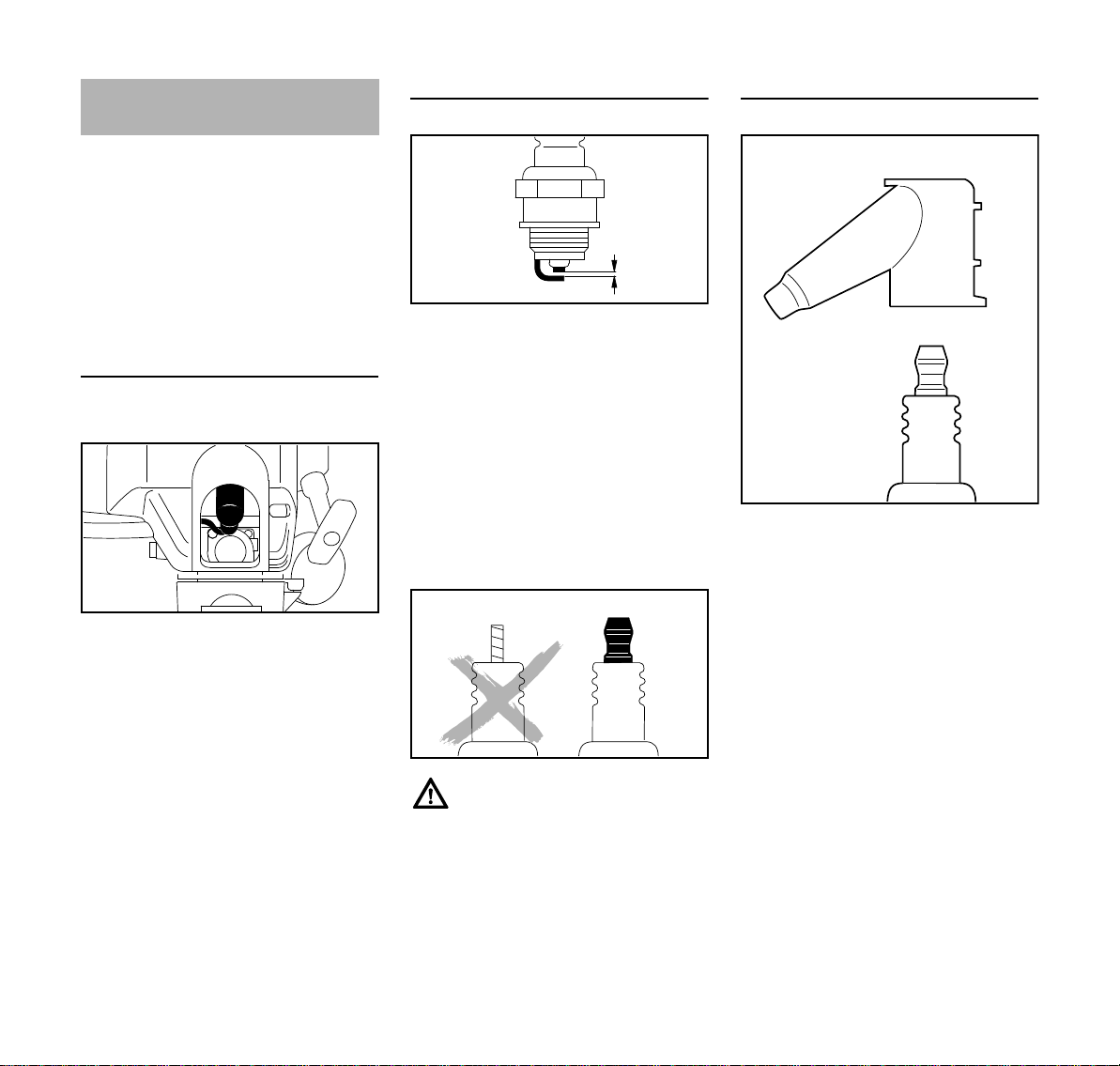
Spark Plug
N If the engine is down on power,
difficult to start or runs poorly at idle
speed, first check the spark plug.
N Fit a new spark plug after about 100
operating hours – or sooner if the
electrodes are badly eroded. Install
only suppressed spark plugs of the
type approved by STIHL – see
"Specifications".
Removing the Spark Plug
N Move the slide control to STOP-0.
Checking the spark plug
N Clean dirty spark plug.
N Check electrode gap (A) and
readjust if necessary – see
"Specifications".
N Rectify the problems which have
caused fouling of the spark plug.
Possible causes are:
– Too much oil in fuel mix.
– Dirty air filter.
– Unfavorable running conditions.
Installing the Spark Plug
N Screw the spark plug (3) into the
cylinder and fit the boot (2) (press it
down firmly).
N Pull off the spark plug boot (1).
N Unscrew the spark plug.
16
If the spark plug comes with a
detachable adapter nut (1), screw the
adapter onto the thread and tighten it
down firmly to reduce the risk of arcing
and fire.
KM 85 R

English
1
1
1
2
3
4
392BA013 KN
5
392BA014 KN
6
7
392BA015 KN
Replacing the Starter Rope
and Rewind Spring
Removing the Starter Cover
N Take out the screws (1).
N Lift the cover (2) away from the
tank (3) and pull it out from under
the shroud (4).
Remove the rope rotor.
N Take out the screw (5) and remove
the rope rotor.
The rewind spring is seated in the rope
rotor and may pop out and uncoil if care
is not taken. The pieces of broken spring
may be under tension and fly apart
unexpectedly when you remove the rope
rotor – to help reduce the risk of injury,
wear face protection and work gloves.
Replacing the starter rope
N Use a screwdriver to pry the cap (6)
out of the starter grip.
N Remove the remaining rope from
the rotor and grip, making sure the
ElastoStart sleeve is not pushed out
of the grip.
N Tie a simple overhand knot in the
new rope and then thread it through
the top of the grip and the rope
bushing (7).
N Refit the cap in the grip.
KM 85 R
17

English
392BA024 KN
a
389BA029 KN
a = 2mm
(0.08 in)
8
392BA025 KN
392BA044 KN
N Thread the rope through the rotor
and secure it with a simple
overhand knot.
N Go to "Installing the Rope Rotor".
Replacing a broken rewind spring
Two types of replacement springs are
available from the factory:
– A ready-to-fit rewind spring secured
with a wire retainer.
– A rope rotor with pre-installed
rewind spring.
Installing the ready-to-fit rewind spring
N Lubricate the spring with a few
drops of non-resinous oil – see
"Special Accessories" – do not open
the wire retainer!
N Carefully remove the parts of the old
spring from the starter cover and
rope rotor.
N Insert the new rewind spring in the
rope rotor and, at the same time,
engage the outer spring loop in the
rotor’s recess – the wire retainer
slips off in this process. If the spring
pops out and uncoils, refit it in the
counterclockwise direction, starting
outside and working inwards.
N Go to "Installing the Rope Rotor".
18
Installing rope rotor with rewind spring
N Carefully unpack the new rope rotor
with rewind spring. The spring may
pop out if not handled with care –risk
of injury.
N Lubricate the spring with a few
drops of non-resinous oil – see
"Special Accessories".
N Go to "Installing the Rope Rotor".
Installing the Rope Rotor
N Check dimension a for inner spring
anchor loop and bend it slightly if
necessary.
N Coat rope rotor bearing bore with
non-resinous oil – see "Special
Accessories".
N Slip the rotor over the starter post –
turn it back and forth to engage the
anchor loop (8) of the rewind spring.
N Insert the screw (5) and tighten it
down firmly.
N Go to "Tensioning the Rewind
Spring".
Tensioning the rewind spring
N Make a loop in the unwound starter
rope and use it to turn the rope rotor
six full revolutions
counterclockwise.
N Hold the rotor steady. Pull out and
straighten the twisted rope.
N Let go of the rotor.
N Release the rope slowly so that it
winds onto the rotor.
N Check spring tension:
KM 85 R

English
1
1
1
2
3
4
393BA045 KN
– The starter grip must be firmly
seated in the rope bushing. If the
grip droops to one side: Add one
more turn on rope rotor to increase
spring tension
– When the starter rope is fully
extended it must still be possible to
rotate the rotor another half turn. If
this is not the case, the spring is
overtensioned and could break.
Take one turn of the rope off the
rotor.
N Go to "Fitting the Starter Cover".
Fitting the Starter Cover
Storing the Machine
For periods of 3 months or longer
N Drain and clean the fuel tank in a
well ventilated area.
N Dispose of fuel properly in
accordance with local
environmental requirements.
N Run the engine until the carburetor
is dry – this helps prevent the
carburetor diaphragms sticking
together.
N Thoroughly clean the machine – pay
special attention to the cylinder fins
and air filter.
N Remove, clean and inspect the
working tool.
N Store the machine in a dry, high or
locked location, out of the reach of
children and other unauthorized
persons.
N Push the upper mounting boss of
the cover (2) under the shroud (4).
N Line up the tank and push the
bottom of the cover onto the tank.
N Insert the screws (1) and tighten
them down firmly.
KM 85 R
19

English
Maintenance and Care
The following intervals apply to normal operating conditions only. If your daily work
ing time is longer or operating conditions are difficult (very dusty work area, etc.),
shorten the specified intervals accordingly.
Complete machine
Control handle Check operation XX
Air filter
Pickup body in fuel tank
Fuel tank Clean XX
Carburetor
Spark plug
Cooling inlets
Sparl arresting screen
All accessible screws and nuts (not adjust
ing screws)
Antivibration elements
Safety labels Replace X
1)
not in all versions, market-specific
2)
STIHL recommends a STIHL servicing dealer.
1)
in muffler
Visual inspection (condition, leaks) XX
Clean X
Clean XX
Replace X
Check X
Replace XXX
Check idle adjustment – the working tool
must not move
Adjusting Idle Speed X
Adjust electrode gap X
Replace after every 100 operating hours
Visual Inspection X
Clean X
Check XX
Clean or replace XX
-
Retighten X
Check XXX
Have replaced by dealer
2)
-
before starting work
after finishing work or daily
after each refueling stop
XX
weekly
monthly
every 12 months
if problem
if damaged
if required
X
20
KM 85 R

English
Minimize Wear and Avoid
Damage
Observing the instructions in this manual
helps reduce the risk of unnecessary
wear and damage to the power tool.
The power tool must be operated,
maintained and stored with the due care
and attention described in this owner's
manual.
The user is responsible for all damage
caused by non-observance of the safety
precautions, operating and maintenance
instructions in this manual. This includes
in particular:
– Alterations or modifications to the
product not approved by STIHL.
– Using tools or accessories which
are neither approved or suitable for
the product or are of a poor quality.
– Using the product for purposes for
which it was not designed.
– Using the product for sports or
competitive events.
– Consequential damage caused by
continuing to use the product with
defective components.
Maintenance Work
All the operations described in the
"Maintenance Chart" must be performed
on a regular basis. If these maintenance
operations cannot be performed by the
owner, they should be performed by a
servicing dealer.
STIHL recommends that you have
servicing and repair work carried out
exclusively by an authorized STIHL
servicing dealer. STIHL dealers are
regularly given the opportunity to attend
training courses and are supplied with
the necessary technical information.
If these maintenance operations are not
carried out as specified, the user
assumes responsibility for any damage
that may occur. Among other parts, this
includes:
– Damage to the engine due to
neglect or deficient maintenance
(e.g. air and fuel filters), incorrect
carburetor adjustment or
inadequate cleaning of cooling air
inlets (intake ports, cylinder fins).
– Corrosion and other consequential
damage resulting from improper
storage.
– Damage to the machine resulting
from the use of poor quality
replacement parts.
Parts Subject to Wear and Tear
Some parts of the power tool are subject
to normal wear and tear even during
regular operation in accordance with
instructions and, depending on the type
and duration of use, have to be replaced
in good time. Among other parts, this
includes:
– Clutch
– Filters (air, fuel)
– Rewind starter
– Spark plug
KM 85 R
21

English
16
#
4
9
11
10
15
8
18
19
462BA005 KN
1
2
3
6
7
17
5
13
12
14
Main Parts
1 Fuel pump
2 Choke lever
3 Carburetor adjusting screws
4 Starter grip
5 Fuel filler cap
6 Fuel tank
7 Muffler (some versions with spark
arresting screen)
8 Carrying ring
9 Slide control
10 Throttle trigger
11 Throttle trigger interlock
12 Spark plug boot
13 Air filter cover
14 Machine support
15 Loop handle
16 Barrier bar
17 Drive tube
18 Coupling sleeve
19 Wing screw
# Serial number
22
KM 85 R

English
Specifications
Engine
Single cylinder two-stroke engine
Displacement: 25.4 cm
Bore: 34 mm
Stroke: 28 mm
Engine power to
ISO 8893:
0.95 kW (1.3 HP)
at 8,500 rpm
Idle speed: 2,800 rpm
Cut-off speed (rated): 10,500 rpm
Ignition System
Electronic magneto ignition
Spark plug (resistor
type):
Bosch WSR 6 F,
NGK BPMR 7 A
Electrode gap: 0.5 mm
Fuel System
All position diaphragm carburetor with
integral fuel pump
Fuel tank capacity: 0.44 l
Weight
dry, without KombiTool
KM 85 R: 4.0 kg
3
Noise and Vibration Data
For further details on compliance with
Vibration Directive 2002/44/EC see
www.stihl.com/vib/
KombiTool
For version see "Approved
KombiTools".
Noise and vibration data measurements
include idling and rated maximum speed
in the following ratios.
FCS-KM, FCB-KM, FS-KM,
FSB-KM, FH-KM and HT-KM 1:1
HL-KM 1:4
BF-KM, BK-KM, KB-KM,
KW-KM, BG-KM and SP-KM 1:6
Sound pressure level L
peq
to
ISO 11201, ISO 22868, ISO 6081,
ISO 7917
KM 85 R: 91 dB(A) ... 97 dB(A)
Sound power level L
weq
to
EN ISO 11680-1, ISO 10884,
ISO 22868, ISO 3744
KM 85 R: 104 dB(A) ... 108 dB(A)
Vibration measurement a
hv,eq
to
ISO 11789, ISO 20643, ISO 22867,
ISO 7916, ISO 8662
Handle, left
KM 85 R: 2.2 m/s
2
... 8.5 m/s
2
Handle, right
KM 85 R: 4.8 m/s2 ... 8.2 m/s
2
The K-factor in accordance with
Directive 2006/42/EC is 2.5 dB(A) for
the sound pressure level and sound
power level; the K-factor in accordance
with Directive 2006/42/EC is 2.0 m/s
2
for the vibration measurement.
REACH
REACH is an EC regulation and stands
for the Registration, Evaluation,
Authorisation and Restriction of
Chemical substances.
For information on compliance with the
REACH regulation (EC) No. 1907/2006
see www.stihl.com/reach.
KM 85 R
23

English
Special Accessories Maintenance and Repairs EC Declaration of Conformity
– Safety glasses
– Shoulder strap
– Full harness
– Combination wrench
– Carburetor screwdriver
– STIHL ElastoStart (starter rope with
grip)
– Special resin-free lubricating oil
Contact your STIHL dealer for more
information on these and other special
accessories.
See also notes on special accessories in
the KombiTool instruction manual.
Users of this machine may only carry out
the maintenance and service work
described in this user manual. All other
repairs must be carried out by a
servicing dealer.
STIHL recommends that you have
servicing and repair work carried out
exclusively by an authorized STIHL
servicing dealer. STIHL dealers are
regularly given the opportunity to attend
training courses and are supplied with
the necessary technical information.
When repairing the machine, only use
replacement parts which have been
approved by STIHL for this power tool or
are technically identical. Only use highquality replacement parts in order to
avoid the risk of accidents and damage
to the machine.
STIHL recommends the use of original
STIHL replacement parts.
Original STIHL parts can be identified by
the STIHL part number, the {
logo and the STIHL parts symbol K
(the symbol may appear alone on small
parts).
ANDREAS STIHL AG & Co. KG
Badstr. 115
D-71336 Waiblingen
confirms that the product described
below
Category: KombiEngine
Make: STIHL
Type: KM 85 R
Serial identification: 4137
Displacement: 25.4 cm
conforms to the specifications of
Directives 2006/42/EC and
2004/108/EC and has been developed
and manufactured in compliance with
the following standards:.
EN ISO 12100, EN 55012,
EN 61000-6-1 (in conjunction with the
following KombiTools: BF-KM, BK-KM,
BG-KM, FCB-KM, FCS-KM, FH-KM,
FS-KM, FSB-KM, HL-KM, HT-KM,
KB-KM, KW-KM and SP-KM).
The KombiEngine described here may
be operated only in conjunction with the
KombiTools approved by STIHL for use
with this KombiEngine.
Technical documents deposited at:
ANDREAS STIHL AG & Co. KG
Produktzulassung (Product Licensing)
The year of manufacture and serial
number are applied to the product.
3
24
KM 85 R

English
000BA025 LÄ
Done at Waiblingen, 24.08.2009
ANDREAS STIHL AG & Co. KG
Elsner
Director Group Product Management
Quality Certification
All STIHL products comply with the
highest quality standards.
An independent organization has
certified that all products manufactured
by STIHL meet the strict requirements of
the ISO 9001 standard for quality
management systems in terms of
product development, materials
purchasing, production, assembly,
documentation and customer service.
KM 85 R
25

0458-462-0121
englisch
G
www.stihl.com
*04584620121*
0458-462-0121
 Loading...