


KM 85 R
2 - 22
2 - 22
22 - 40
22 - 40
Manual de instrucciones
Instruction Manual

español
Índice
1 Sistema combinado.................................... 2
2 Notas relativas a este manual de instruccio‐
nes.............................................................. 2
3 Indicaciones relativas a la seguridad y téc‐
nica de trabajo............................................ 3
4 Herramientas combinadas permitidas........ 7
5 Montar el asidero tubular cerrado............... 7
6 Ajustar el cable del acelerador....................8
7 Combustible................................................ 8
8 Repostar combustible................................. 9
9 Arrancar / parar el motor...........................10
10 Indicaciones para el servicio.....................12
11 Limpiar el filtro de aire...............................12
12 Ajustar el carburador.................................14
13 Rejilla parachispas en el silenciador.........15
14 Bujía..........................................................15
15 Guardar la máquina.................................. 16
16 Comprobación y mantenimiento por el
usuario...................................................... 17
17 Comprobación y mantenimiento por el dis‐
tribuidor especializado.............................. 17
18 Instrucciones de mantenimiento y conserva‐
ción........................................................... 18
19 Minimizar el desgaste y evitar daños........19
20 Componentes importantes........................20
21 Datos técnicos.......................................... 20
22 Indicaciones para la reparación................ 21
23 Gestión de residuos.................................. 21
24 Declaración de conformidad UE............... 21
Distinguidos clientes:
Muchas gracias por haber depositado su con‐
fianza en un producto de calidad de la
empresa STIHL.
Este producto se ha confeccionado con moder‐
nos procedimientos de fabricación y amplias
medidas para afianzar la calidad. Procuramos
hacer todo lo posible para que usted esté satis‐
fecho con este producto y pueda trabajar con él
sin problemas.
En el caso de que tenga usted alguna pregunta
sobre este producto, diríjase a su distribui‐
dor STIHL o directamente a nuestra empresa de
distribución.
2 0458-462-8721-B
Atentamente
Dr. Nikolas Stihl
1 Sistema combinado
En el sistema combinado STIHL se combinan
diferentes motores universales y herramientas
combinadas para formar una máquina. La uni‐
dad operativa constituida por el motor universal y
la herramienta combinada se denomina máquina
en este manual de instrucciones.
Por lo tanto, los manuales de instrucciones para
el motor universal y la herramienta combinada
constituyen el manual de instrucciones completo
para la máquina.
Antes de ponerla en marcha por primera vez,
leer con atención siempre los dos manuales de
instrucciones y guardarlos en un lugar seguro
para posteriores consultas.
2 Notas relativas a este
manual de instrucciones
2.1 Símbolos gráficos
Todos los símbolos gráficos existentes en la
máquina están explicados en este manual de
instrucciones.
2.2 Marcación de párrafos de texto
ADVERTENCIA
Advertencia de peligro de accidente y riesgo de
lesiones para personas y de daños materiales
graves.
INDICACIÓN
Advertencia de daños de la máquina o de los
diferentes componentes.
2.3 Perfeccionamiento técnico
STIHL trabaja permanentemente en el perfeccio‐
namiento de todas las máquinas y dispositivos;
por ello, nos reservamos los derechos relativos a
las modificaciones del volumen de suministro en
la forma, técnica y equipamiento.
De los datos e ilustraciones de este manual de
instrucciones no se pueden deducir por lo tanto
derechos a reclamar.
Original de Instrucciones de servicio
0000007890_006_E
Impreso en papel blanqueado sin cloro.
Los colores de la impresión contienen aceites vegetales, por lo que el papel es reciclable.
© ANDREAS STIHL AG & Co. KG 2022
0458-462-8721-B. VA0.M21.

3 Indicaciones relativas a la seguridad y técnica de trabajo español
3 Indicaciones relativas a la
seguridad y técnica de tra‐
bajo
Es necesario tomar medidas de
seguridad especiales al trabajar con
una máquina a motor.
Antes de ponerlos en servicio por pri‐
mera vez, se han de leer siempre con
atención las dos instrucciones de uso
(la del motor universal y la de la
herramienta combinada) y se han de
guardar luego en un lugar seguro
para posteriores consultas. La inob‐
servancia de las instrucciones de uso
puede tener consecuencias mortales.
Observar las normas de seguridad del país,
p. ej., de las asociaciones profesionales del sec‐
tor, organismos sociales y autoridades compe‐
tentes en materia de prevención de accidentes
en el trabajo y de otro tipo.
Al trabajar por primera vez con esta máquina,
dejar que el vendedor o un experto le muestre
cómo se maneja con seguridad o participar en
un cursillo especializado.
Los menores de edad no deberán trabajar con
esta máquina a motor – a excepción de jóvenes
de más de 16 años que estén aprendiendo bajo
la tutela de un instructor.
No permitir que se acerquen niños, animales ni
espectadores.
Si la máquina no se utiliza, se deberá colocar de
forma que nadie corra peligro. La máquina
deberá ser inaccesible para personas ajenas.
El usuario es el responsable de los accidentes o
peligros que afecten a otras personas o sus pro‐
piedades.
Prestar o alquilar esta máquina a motor solo a
quienes estén familiarizados con este modelo y
su manejo y entregarles siempre las instruccio‐
nes de uso del motor universal y de la herra‐
mienta combinada.
El uso de máquinas que emitan ruidos puede
estar limitado en el tiempo por disposiciones
nacionales o locales.
Para trabajar con esta máquina a motor, se
deberá estar descansado, sentirse bien y estar
en buenas condiciones.
Quien, por motivos de salud, no pueda realizar
esfuerzos, debería consultar con su médico si
puede trabajar con una máquina a motor.
Solo para implantados con marcapasos: el sis‐
tema de encendido de esta máquina genera un
campo electromagnético muy pequeño. No se
puede descartar por completo que influya en
algunos tipos de marcapasos. Para evitar ries‐
gos sanitarios, STIHL recomienda que consulte
a su médico y al fabricante del marcapasos.
No se debe trabajar con esta máquina a motor
tras la ingesta de bebidas alcohólicas, medica‐
mentos que disminuyan la capacidad de reac‐
ción o de drogas.
Utilizar la máquina a motor -– según la herra‐
mienta combinada utilizada – solo para los traba‐
jos especificados en el manual de instrucciones
de la herramienta combinada.
No se deberá utilizar la máquina para otros fines,
¡peligro de accidente!
Operar con el motor universal únicamente
estando montada la herramienta combinada – en
caso contrario, pueden producirse daños en la
máquina.
Acoplar únicamente herramientas combinadas o
accesorios que hayan sido autorizados
por STIHL para esta máquina o piezas técnica‐
mente iguales. Tener en cuenta sin falta el capí‐
tulo "Herramientas combinadas permitidas". En
caso de dudas al respecto, acudir a un distribui‐
dor especializado. Emplear solo herramientas o
accesorios de alta calidad. De lo contrario, existe
el peligro de accidentes o daños en la máquina.
STIHL recomienda emplear herramientas y
accesorios originales STIHL. Sus características
se ajustan de forma óptima al producto y las exi‐
gencias del usuario.
No efectuar modificaciones en la máquina, ya
que podría afectar a la seguridad. STIHL renun‐
cia a cualquier responsabilidad por daños perso‐
nales y materiales que se produzcan al emplear
accesorios no autorizados.
No emplear hidrolimpiadoras de alta presión
para limpiar la máquina. El chorro de agua duro
puede dañar piezas de la máquina.
3.1 Ropa y equipo
Utilizar la ropa y el equipo reglamentarios.
No ponerse ropa que se pueda
enganchar en la madera, arbustos o
piezas de la máquina que estén en
movimiento. Tampoco bufanda, cor‐
bata ni artículos de joyería. Reco‐
gerse el pelo largo y asegurarlo, de
0458-462-8721-B 3

español 3 Indicaciones relativas a la seguridad y técnica de trabajo
manera que quede por encima de los
hombros.
Véase también las indicaciones relativas a
"Ropa y equipo" en el manual de instrucciones
de la herramienta combinada utilizada.
3.2 Transporte de la máquina
Parar siempre el motor.
En vehículos: asegurar la máquina para que no
vuelque, no se dañe ni se derrame combustible.
Véase también las indicaciones relativas a
"Transportar la máquina" en el manual de ins‐
trucciones de la herramienta combinada utili‐
zada.
3.3 Repostaje
La gasolina es altamente inflamable:
mantener la distancia a cualquier
llama, no derramar combustible y no
fumar.
Parar el motor antes de repostar.
No repostar mientras el motor está aún caliente:
el combustible puede rebosar ¡peligro de incen‐
dio!
Abrir con cuidado el cierre del depósito para que
se reduzca lentamente la presión existente y no
salga combustible despedido.
Repostar en lugares bien ventilados. Si se
derrama combustible, limpiar la máquina inme‐
diatamente prestando atención a que la ropa no
se moje con combustible; si fuera necesario,
cambiársela inmediatamente.
Después de repostar, apretar el cie‐
rre roscado del depósito lo más firme‐
mente posible.
Así se reduce el riesgo de que se afloje el cierre
del depósito por las vibraciones del motor y que
salga combustible.
Fijarse en que no haya fugas y no arrancar el
motor si sale combustible, ¡peligro de muerte por
quemaduras!
3.4 Antes de arrancar
Comprobar que el estado de la máquina cumpla
con las condiciones de seguridad; tener en
cuenta los capítulos correspondientes de los
manuales de instrucciones:
Comprobar la estanqueidad del sistema de
–
combustible, especialmente las piezas visi‐
bles, como p. ej., el cierre del depósito, las
uniones de tubos flexibles, la bomba manual
de combustible (solo para máquinas equipa‐
das con bomba manual de combustible). En
caso de fugas o daños, no arrancar el motor,
¡peligro de incendio! Antes de poner en mar‐
cha la máquina, acudir a un distribuidor espe‐
cializado para su reparación
La combinación de herramienta de corte, pro‐
–
tector, empuñadura y cinturón de porte deberá
estar permitida y todas las piezas deberán
estar correctamente montadas
El cursor del mando unificado/interruptor de
–
parada se puede poner con facilidad en STOP
o 0
El bloqueo del acelerador y el acelerador se
–
deberán mover con suavidad; el acelerador
debe volver automáticamente a la posición de
ralentí
Comprobar que el enchufe del cable de
–
encendido esté firme. Si está flojo, pueden
producirse chispas que inflamen la mezcla de
combustible y aire que salga, ¡peligro de
incendio!
No modificar los dispositivos de mando ni los
–
de seguridad
Las empuñaduras tienen que estar limpias y
–
secas, libres de aceite y suciedad; esto es
importante para manejar la máquina de forma
segura
Ajustar el cinturón de porte y la empuñadura
–
con arreglo a la estatura
La máquina solo se deberá utilizar si cumple las
condiciones de seguridad para el trabajo, ¡peli‐
gro de accidente!
Para casos de emergencia al utilizar cinturones
de porte: practicar la deposición rápida de la
máquina. Al practicar, no arrojar la máquina al
suelo, a fin de evitar que se dañe.
Véase también las indicaciones relativas a
"Antes de arrancar" en el manual de instruccio‐
nes de la herramienta combinada utilizada.
4 0458-462-8721-B

002BA273 KN
3 Indicaciones relativas a la seguridad y técnica de trabajo español
3.5 Arrancar el motor
Al menos a 3 m del lugar donde se ha repostado
y nunca en lugares cerrados.
Hacerlo solo sobre terreno llano, adoptar una
postura estable y segura, sujetar la máquina de
forma segura – la herramienta de trabajo no
deberá tocar objeto alguno ni el suelo, ya que
puede empezar a girar al arrancar.
Evitar el contacto con la herramienta de trabajo,
¡peligro de lesiones!
No arrancar el motor con la máquina suspendida
de la mano, hacerlo tal como se describe en el
manual de instrucciones. La herramienta de tra‐
bajo sigue funcionando todavía un momento tras
soltar el acelerador (efecto de funcionamiento
por inercia).
Comprobar el ralentí: la herramienta de trabajo
debe estar parada en ralentí con el acelerador
en reposo.
Mantener apartados materiales fácilmente infla‐
mables (p. ej. virutas de madera, cortezas de
árbol, hierba seca, combustible) de la corriente
caliente de gases de escape y de la superficie
caliente del silenciador, ¡peligro de incendio!
Véase también las indicaciones relativas a
"Arrancar / parar el motor" en el manual de ins‐
trucciones de la herramienta combinada utili‐
zada.
3.6 Sujetar y guiar la máquina
Agarrar siempre la máquina por las empuñadu‐
ras con ambas manos.
Adoptar siempre una postura estable y segura.
La mano izquierda, en el manillar cerrado; la
derecha, en la empuñadura de mando – también
para zurdos.
3.7 Durante el trabajo
En caso de peligro inminente, o de emergencia,
parar inmediatamente el motor: poner el cursor
del mando unificado/interruptor de parada
en STOP o 0.
Prestar atención a que el ralentí sea perfecto a
fin de que la herramienta de trabajo deje de
moverse al soltar el acelerador. Si, pese a ello,
la herramienta de trabajo se mueve en ralentí,
encargar la reparación a un distribuidor especia‐
lizado. Controlar o corregir el ajuste del ralentí
con regularidad. STIHL recomienda un distribui‐
dor especializado STIHL.
Al llevar un protector para los oídos, hay que
prestar más atención y tener más precaución ya
que se perciben peor las señales de aviso de
peligro (gritos, señales acústicas y similares).
Hacer siempre las pausas necesarias en el tra‐
bajo para prevenir el cansancio y el agotamiento,
¡peligro de accidente!
Trabajar con tranquilidad y prudencia y solo si
las condiciones de luz y visibilidad son adecua‐
das. Trabajar con precaución, no poner en peli‐
gro a otras personas.
Utilizar la máquina solo en los campos de aplica‐
ción indicados en el manual de instrucciones de
la herramienta combinada.
La máquina produce gases de
escape tóxicos en cuanto se pone en
marcha el motor. Estos gases pue‐
den ser inodoros e invisibles pero
pueden contener hidrocarburos y
benceno sin quemar. No trabajar
nunca con la máquina en locales
cerrados o mal ventilados, incluso
con máquinas de catalizador.
Al trabajar en zanjas, fosas o espacios reduci‐
dos, se ha de garantizar que haya siempre sufi‐
ciente renovación de aire, ¡peligro de muerte por
intoxicación!
En caso de malestar, dolores de cabeza, dificul‐
tades de visión (p. ej. reducción del campo
visual), disminución de la audición, mareos y
pérdida de concentración, dejar de trabajar
inmediatamente – estos síntomas se pueden
producir, entre otras causas, por la alta concen‐
tración de gases de escape: ¡peligro de acci‐
dente!
Trabajar con la máquina tratando de hacer poco
ruido y acelerando poco; no dejar innecesaria‐
mente el motor en marcha, dar gas solo para tra‐
bajar.
0458-462-8721-B 5

español 3 Indicaciones relativas a la seguridad y técnica de trabajo
No fumar trabajando con la máquina ni en el
entorno inmediato de la misma: ¡peligro de
incendio! Del sistema de combustible pueden
salir vapores de gasolina inflamables.
Los polvos, la neblina y el humo que se generan
durante el trabajo pueden ser nocivos para la
salud. Ponerse una mascarilla si se produce
mucho polvo o humo.
En el caso de que la máquina haya sufrido inci‐
dencias para las que no está preparada
(p. ej., golpes o caídas), se ha de comprobar sin
falta que funcione de forma segura antes de
continuar el trabajo, véase también "Antes de
arrancar". Comprobar especialmente la estan‐
queidad del sistema de combustible y el funcio‐
namiento de los dispositivos de seguridad. De
ningún modo se deberá seguir trabajando con
máquinas que ya no sean seguras. En caso de
dudas, acudir a un distribuidor especializado.
No trabajar con gas de arranque ya que el régi‐
men del motor no se puede regular estando el
acelerador en esta posición.
Antes de ausentarse de la máquina: parar el
motor.
Para cambiar la herramienta combinada o la
herramienta de trabajo, parar el motor – ¡peligro
de lesiones!
3.8 Vibraciones
La utilización prolongada de la máquina puede
provocar trastornos circulatorios en las manos
("enfermedad de los dedos blancos") originados
por las vibraciones.
No se puede establecer una duración general
del uso, porque ésta depende de varios factores
que influyen en ello.
El tiempo de uso se prolonga:
Protegiendo las manos (guantes calientes)
–
Haciendo pausas
–
El tiempo de uso se acorta por:
La predisposición personal a una mala circula‐
–
ción sanguínea (síntomas: dedos fríos con fre‐
cuencia, hormigueo)
Bajas temperaturas
–
Magnitud de la fuerza de sujeción (la sujeción
–
firme dificulta el riego sanguíneo)
En el caso trabajar con regularidad y durante
mucho tiempo con la máquina y manifestarse
repetidamente tales síntomas (p. ej. hormigueo
en los dedos), se recomienda someterse a un
examen médico.
3.9 Mantenimiento y reparaciones
Efectuar con regularidad los trabajos de mante‐
nimiento de la máquina. Efectuar únicamente
trabajos de mantenimiento y reparaciones que
estén descritos en el manual de instrucciones.
Encargar todos los demás trabajos a un distribui‐
dor especializado.
STIHL recomienda encargar los trabajos de
mantenimiento y las reparaciones siempre a un
distribuidor especializado STIHL. Los distribuido‐
res especializados STIHL siguen periódicamente
cursillos de instrucción y tienen a su disposición
las informaciones técnicas.
Emplear sólo repuestos de gran calidad. De no
hacerlo, existe el peligro de que se produzcan
accidentes o daños en la máquina. Si tiene pre‐
guntas al respecto, consulte a un distribuidor
especializado.
STIHL recomienda emplear piezas de repuesto
originales STIHL. Las propiedades de éstas
están armonizadas óptimamente con la máquina
y las exigencias del usuario.
Para la reparación, el mantenimiento y la lim‐
pieza, parar siempre el motor – ¡peligro de lesio‐
nes! – Excepción: ajuste del carburador y el
ralentí.
Estando desacoplado el enchufe del cable de
encendido o con la bujía desenroscada, poner
en movimiento el motor con el dispositivo de
arranque únicamente si el cursor del mando uni‐
ficado / interruptor de parada se encuentra
en STOP o bien 0 – peligro de incendio por chis‐
pas de encendido fuera del cilindro.
No realizar trabajos de mantenimiento en la
máquina ni guardar ésta cerca de fuego abierto –
peligro de incendio debido al combustible.
Comprobar periódicamente la estanqueidad del
cierre del depósito.
Emplear únicamente bujías en perfecto estado,
autorizadas por STIHL – véase "Datos técnicos".
Inspeccionar el cable de encendido (aislamiento
perfecto, conexión firme).
Comprobar con regularidad el silenciador en
cuanto a perfecto estado.
No trabajar estando dañado el silenciador ni sin
éste – ¡peligro de incendio! – ¡daños en los
oídos!
No tocar el silenciador si está caliente – ¡peligro
de quemaduras!
6 0458-462-8721-B

2
002BA098 KN
1
1
5
4
002BA099 KN
2
3
6
7
4 Herramientas combinadas permitidas español
El estado de los elementos antivibradores influye
en el comportamiento de vibración – controlar
con regularidad dichos elementos.
4 Herramientas combinadas
permitidas
En el motor universal se pueden montar las
siguientes herramientas combinadas STIHL:
Herramienta combi‐
nada
FS‑KM Guadaña con cabezal de
1)
FS‑KM
FSB‑KM Guadaña con cabezal de
HL‑KM 145° Cortasetos de altura,
HL‑KM 0° Cortasetos de altura
FH‑KM 145°
BG‑KM Soplador
HT‑KM
BF‑KM Fresadora de suelo
FCB‑KM Cortabordes
FCS‑KM Cortabordes
SP‑KM Cosechadora especial
KB‑KM Cepillo barredor
KW-KM Rodillo barredor
Aplicación
corte
Guadaña con hoja cor‐
tahierbas
corte
ajustable
Cortamatorrales
Podadora de altura
► Introducir las tuercas cuadradas (1) en el
estribo (2) – hacer coincidir los orificios
5 Montar el asidero tubular
cerrado
En el volumen de suministro de la máquina
existe un estribo (limitador de paso). Montar el
estribo en el asidero tubular cerrado.
► Colocar la abrazadera (3) en el asidero tubular
1)
emplear el estribo (limitador de paso), incluido en el volumen de suministro, en el manillar cerrado;
véase también "Montar el manillar cerrado"
0458-462-8721-B 7
cerrado (4) y aplicarlos juntos al vástago (5)
► Colocar la abrazadera (6)

A
9
8
4
002BA353 KN
002BA163 KN
2
1
002BA161 KN
español 6 Ajustar el cable del acelerador
► Aplicar el estribo (2) – tener en cuenta la posi‐
ción
► Hacer coincidir los orificios
► Insertar los tornillos (7) en los orificios – y
enroscarlos en el estribo hasta el tope
► Oprimir el fiador de la empuñadura de mando
hasta el extremo de la ranura con una herra‐
mienta
► Oprimir a fondo el bloqueo del acelerador (1) y
el acelerador (2) (posición de pleno gas) – de
esta manera se ajusta correctamente el cable
► Fijar el asidero tubular cerrado (4) a una dis‐
tancia de (A) aprox. 20 cm (8 in) delante de la
empuñadura de mando (8)
► Alinear el asidero tubular cerrado
► Apretar los tornillos – para ello, asegurar las
tuercas con contratuercas si es necesario.
El manguito (9) se monta según qué países y se
ha de encontrar entre el asidero tubular cerrado
y la empuñadura de mando.
Dejar el estribo (limitador de paso) siempre mon‐
tado.
6 Ajustar el cable del acele‐
rador
El ajuste correcto del cable del acelerador es
una condición previa para que funcionen correc‐
tamente el gas de arranque, ralentí y pleno gas.
Ajustar el cable del acelerador sólo estando
montada la máquina completa.
del acelerador
7 Combustible
El motor se ha de alimentar con una mezcla
compuesta por gasolina y aceite de motor.
ADVERTENCIA
Evitar el contacto directo de la piel con el com‐
bustible y la inhalación de vapores del mismo.
7.1 STIHL MotoMix
STIHL recomienda emplear STIHL MotoMix.
Este combustible mezclado está exento de ben‐
ceno y plomo, se distingue por un alto índice
octano y tiene siempre la proporción de mezcla
correcta.
El STIHL MotoMix está mezclado para obtener la
máxima durabilidad del motor con el aceite de
motor de dos tiempos HP Ultra STIHL.
MotoMix no está disponible en todos los merca‐
dos.
8 0458-462-8721-B

8 Repostar combustible español
7.2 Mezclar combustible
INDICACIÓN
Si los productos de servicio no son apropiados o
la proporción de la mezcla no corresponde a la
norma se pueden producir serios daños en el
motor. La gasolina o el aceite de motor de mala
calidad pueden dañar el motor, las juntas anula‐
res, las tuberías y el depósito de combustible.
7.2.1 Gasolina
Emplear solo gasolina de marca con un índice
octano de 90 ROZ, como mínimo – con o sin
plomo.
La gasolina con una proporción de alcohol supe‐
rior al 10% puede provocar anomalías de funcio‐
namiento en motores con ajuste manual del car‐
burador, por lo que no se deberá emplear para
alimentar estos motores.
Los motores equipados con M-Tronic suminis‐
tran plena potencia empleando gasolina con una
proporción de alcohol (E27) de hasta un 27%.
7.2.2 Aceite de motor
Si mezcla usted mismo el combustible, solo se
puede usar un aceite de motor de dos tiempos
STIHL u otro aceite de motor de alto rendimiento
de las clases JASO FB, JASO FC, JASO FD,
ISO-L-EGB, ISO-L-EGC o ISO-L-EGD.
STIHL prescribe el aceite de motor de dos tiem‐
pos STIHL HP Ultra o un aceite de motor de alto
rendimiento similar para poder garantizar los
valores límite de emisiones durante toda la vida
útil de la máquina.
7.2.3 Proporción de la mezcla
Con aceite de motor de dos tiempos STIHL 1:50;
1:50 = 1 parte de aceite + 50 partes de gasolina
7.2.4 Ejemplos
Cantidad de gaso‐
lina
Litros Litros (ml)
1 0,02 (20)
5 0,10 (100)
10 0,20 (200)
15 0,30 (300)
20 0,40 (400)
25 0,50 (500)
► En un bidón homologado para combustible,
echar primero aceite de motor, luego gasolina,
y mezclarlos bien
Aceite de dos tiempos
STIHL 1:50
7.3 Guardar la mezcla de combus‐
tible
Solo en bidones homologados para combustible,
guardándolos en un lugar seguro, seco y fresco,
protegidos contra la luz y el sol.
La mezcla de combustible envejece, mezclar
solo la cantidad que se necesite para algunas
semanas. No guardar la mezcla de combustible
durante más de 30 días. El efecto de la luz, el
sol, altas o bajas temperaturas, pueden echar a
perder con mayor rapidez la mezcla de combus‐
tible.
Sin embargo, la STIHL MotoMix se puede alma‐
cenar hasta 5 años sin problemas.
► Antes de repostar, agitar con fuerza el bidón
con la mezcla
ADVERTENCIA
En el bidón puede generarse presión – abrirlo
con cuidado.
► De vez en cuando, limpiar a fondo el depósito
de combustible y el bidón
Recoger el combustible residual y el líquido utili‐
zado para la limpieza y llevarlos a un punto lim‐
pio.
8 Repostar combustible
0458-462-8721-B 9

389BA031 KN
3
STOP
2
5
6
4
7
002BA181 KN
START
STOP-
1
español 9 Arrancar / parar el motor
8.1 Preparar la máquina
ADVERTENCIA
Tras el repostaje, apretar el cierre del depósito lo
más firmemente posible con la mano.
9 Arrancar / parar el motor
9.1 Elementos de mando
► Antes de repostar combustible, limpiar el cie‐
rre del depósito y sus alrededores, a fin de
que no penetre suciedad en el depósito.
► Posicionar la máquina, de manera que el cie‐
rre del depósito esté orientado hacia arriba
8.2 Repostar combustible
Al repostar, no derramar combustible ni llenar el
depósito hasta el borde. STIHL recomienda utili‐
zar el sistema de llenado STIHL para combusti‐
ble (accesorio especial).
► Abrir el cierre del depósito
► Repostar combustible
1 Bloqueo del acelerador
2 Acelerador
3 Cursor del mando unificado
9.1.1 Posiciones del cursor del mando unifi‐
4 STOP-0 – Motor descon. – el encendido está
5
6 START – Arrancar – el encendido está conec‐
9.1.2 Símbolo en el cursor del mando unifi‐
7
cado
desconectado
F – Funcionamiento – el motor está en mar‐
cha o puede arrancar
tado – el motor se puede poner en marcha
cado
h – Señal de parada y flecha – para desco‐
nectar el motor, empujar el cursor del mando
unificado en el sentido de la flecha que hay
en la señal de parada (h) a STOP-0
10 0458-462-8721-B

393BA017 KN
8
8
393BA018 KN
9
552BA014 KN
552BA015 KN
552BA016 KN
9 Arrancar / parar el motor español
9.2 Arrancar
► Oprimir sucesivamente el bloqueo del acelera‐
dor y el acelerador
► Mantener ambos oprimidos
► Empujar el cursor del mando unificado
a START y sujetarlo asimismo
► Soltar sucesivamente el acelerador, el cursor
del mando unificado y el bloqueo del acelera‐
dor = posición de gas de arranque
► Colocar la máquina en el suelo sobre el apoyo
del motor: la herramienta de trabajo no deberá
tocar el suelo ni ningún objeto – véase tam‐
bién "Arrancar / parar el motor" en el manual
de instrucciones de la herramienta combinada
► Adoptar una postura estable
► Presionar firmemente la máquina contra el
suelo con la mano izquierda – el pulgar, por
debajo de la caja del ventilador
► Ajustar la palanca (8) de la mariposa de arran‐
que a
Con el motor frío
g
Con el motor caliente – aun cuando el
e
motor haya estado ya en marcha, pero
todavía esté frío
INDICACIÓN
¡No poner el pie sobre el vástago ni arrodillarse
encima del mismo!
► Con la mano derecha, agarrar la empuñadura
► Pulsar el fuelle (9) de la bomba manual de
combustible 5 veces, como mínimo – aun
cuando el fuelle esté lleno de combustible
9.2.1 Arrancar
de arranque
► Extraer lentamente la empuñadura de arran‐
que hasta percibir una resistencia y tirar
entonces con rapidez y fuerza de aquélla
INDICACIÓN
No extraer el cordón hasta el extremo del mismo
– ¡peligro de rotura!
► No dejar retroceder bruscamente la empuña‐
dura de arranque – guiarla hacia atrás en sen‐
tido contrario al de extracción, para que el cor‐
0458-462-8721-B 11
dón se enrolle correctamente
► Seguir arrancando
9.2.2 Tras el primer encendido
► Poner la palanca de la mariposa de arranque
en e

español
► Seguir arrancando
9.2.3 Una vez que el motor esté en marcha
► Oprimir inmediata y brevemente el acelerador;
el cursor del mando unificado salta a la posi‐
ción de funcionamiento F – el motor pasa a
ralentí
ADVERTENCIA
Estando correctamente ajustado el carburador,
no deberá moverse la herramienta de trabajo en
régimen de ralentí.
La máquina está lista para el trabajo.
9.3 Parar el motor
► Empujar el cursor del mando unificado en el
sentido de la flecha que hay en la señal de
parada (h) a STOP-0
► Arrancar de nuevo el motor
9.5.2 Ajuste del cable del acelerador
► Comprobar el ajuste del cable del acelerador –
véase "Ajustar el cable del acelerador"
9.5.3 El depósito se ha vaciado por com‐
► Tras el repostaje, pulsar 5 veces, como
mínimo, el fuelle de la bomba manual de com‐
bustible – aun cuando el fuelle esté lleno de
combustible
► Ajustar la palanca de la mariposa de arranque
en función de la temperatura del motor
► Volver a arrancar el motor
10 Indicaciones para el servi‐
cio
10.1 Durante el primer tiempo de
9.4 Con temperaturas muy bajas
Tras ponerse en marcha el motor:
► Oprimir brevemente el acelerador = se desen‐
castra la posición de gas de arranque – el cur‐
sor del mando unificado salta a la posición de
funcionamiento F – el motor pasa a ralentí
► Dar poco gas
► Dejar calentarse brevemente el motor
9.5 Si no arranca el motor
Palanca de la mariposa de arranque
Si tras el primer encendido del motor no se ha
puesto a tiempo la palanca de la mariposa de
arranque en e, el motor estará ahogado.
► Poner la palanca de la mariposa de arranque
en e
► Poner el cursor del mando unificado, la
palanca de bloqueo y el acelerador en la posi‐
ción de gas de arranque
► Arrancar el motor – para ello, tirar con fuerza
del cordón de arranque – pueden hacer falta
entre 10 y 20 intentos
9.5.1 Si no arranca el motor pese a ello
► Poner el cursor del mando unificado en la
posición de STOP-0
► Desmontar la bujía – véase "Bujía"
► Secar la bujía
► Accionar varias veces el mecanismo de arran‐
que – para ventilar la cámara de combustión
► Volver a montar la bujía – véase "Bujía"
► Empujar el cursor del mando unificado
a START
► Poner la palanca de la mariposa de arranque
en e – aun estando frío el motor
12 0458-462-8721-B
Siendo la máquina nueva de fábrica, no se
deberá hacer funcionar sin carga en un margen
elevado de revoluciones hasta haber llenado por
tercera vez el depósito de combustible, a fin de
que no se produzcan esfuerzos adicionales
durante la fase de rodaje. Durante este fase se
tienen que adaptar las piezas móviles entre sí –
en el motor se da una elevada resistencia de
fricción. El motor alcanza su potencia máxima
tras un tiempo de rodaje que corresponde a 5
hasta 15 cargas del depósito.
10.2 Durante el trabajo
Tras un cierto tiempo de servicio a plena carga,
dejar funcionando el motor en ralentí todavía
durante un breve tiempo hasta que la corriente
de aire de refrigeración haya extraído el calor
excesivo, con el fin de que los componentes del
motor (sistema de encendido, carburador) no
queden expuestos a una carga extrema origi‐
nada por la acumulación de calor.
10.3 Después del trabajo
En pausas de servicio breves: dejar enfriarse el
motor. Guardar la máquina con el depósito de
combustible lleno, en un lugar seco que no esté
cerca de fuentes de ignición, hasta el siguiente
servicio. En pausas de servicio de cierta dura‐
ción – véase "Guardar la máquina".
11 Limpiar el filtro de aire
Los filtros de aire sucios disminuyen la potencia
del motor, aumentan el consumo de combustible
y dificultan el arranque.
10 Indicaciones para el servicio
pleto con el motor en marcha
servicio

355BA014 KN
2
1
3
392BA046 KN
2
2
4
392BA047 KN
11 Limpiar el filtro de aire español
Las máquinas pueden estar equipadas de serie
con diferentes tapas de filtro.
11.1 Si disminuye perceptiblemente
la potencia del motor
► Poner la palanca de la mariposa de arranque
en g
Estando encastrada la tapa del filtro
► Oprimir la brida (1) y apartar la tapa del fil‐
tro (2) girándola
Estando atornillada la tapa del filtro
► Aflojar el tornillo (3) y quitar la tapa del fil‐
tro (2)
En ambas ejecuciones
► Eliminar la suciedad más importante de las
zonas circundantes del filtro
► Quitar el filtro de plástico celular y el filtro de
fieltro
► Lavar el filtro de plástico celular en un líquido
detergente limpio y no inflamable (p. ej. agua
jabonosa caliente) y secarlo
► Cambiar el filtro de fieltro – no lavarlo. – para
salir del paso, golpearlo ligeramente o soplarlo
Sustituir las piezas dañadas
► Colocar el filtro de plástico celular (4) en la
tapa del filtro (2)
0458-462-8721-B 13
5
6
392BA048 KN
265BA024 KN
LA
HL
1
3 / 4
español 12 Ajustar el carburador
► Colocar el filtro de fieltro (5) en la caja del fil‐
tro (6) con el rotulado hacia dentro
► Asentar la tapa del filtro
► Encastrar la tapa del filtro o apretar el tornillo
en la tapa del filtro
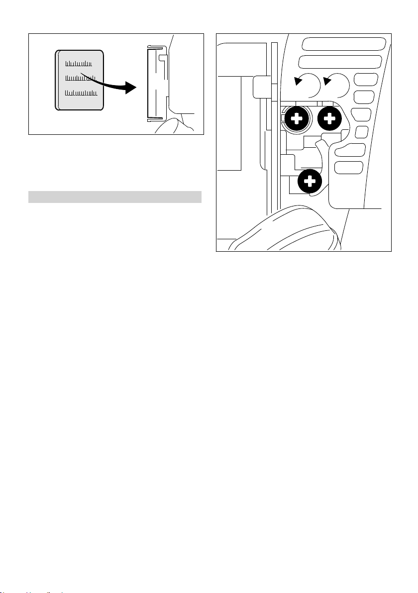
12 Ajustar el carburador
El carburador se ha ajustado en fábrica a valores
estándar.
Este ajuste del carburador está armonizado, de
manera que el motor recibe una mezcla óptima
de combustible y aire en cualesquiera estados
operativos.
En este carburador se pueden efectuar correc‐
ciones en el tornillo regulador principal y en el de
ajuste del ralentí sólo en un estrecho margen.
12.1 Ajuste estándar
► Parar el motor
► Montar la herramienta combinada estando
montada la herramienta de trabajo o la herra‐
mienta de corte
► Comprobar el filtro de aire – limpiarlo o susti‐
tuirlo si lo requiere su estado
► Comprobar el ajuste del cable del acelerador,
ajustarlo si lo requiere su estado – véase
"Ajustar el cable del acelerador"
► Controlar la rejilla parachispas (montada sólo
según qué países) – limpiarla o sustituirla si lo
requiere su estado
► Girar el tornillo regulador principal (H) en sen‐
tido antihorario hasta el tope – 3/4 de vuelta,
como máximo
► Girar con sensibilidad el tornillo de ajuste del
ralentí (L) en el sentido horario hasta que
asiente firmemente, girarlo luego 1 vuelta en
el sentido antihorario
► Poner la máquina en marcha y dejar que se
caliente el motor si es necesario
► Ajustar el ralentí con el tornillo de tope del
ralentí (LA), de manera que no se mueva la
herramienta de corte
12.2 Ajuste de precisión
Si la potencia de motor no es satisfactoria al tra‐
bajar en la sierra, al nivel del mar o tras cambiar
la herramienta de trabajo, puede ser necesario
corregir un poco el ajuste del tornillo regulador
principal (H).
Valor orientativo
Girar el tornillo regulador principal (H) aprox.
1/4 de vuelta por cada 1000 m de diferencia de
altitud
Condiciones para el ajuste
► Realizar el ajuste estándar para el tornillo de
ajuste del ralentí (L)
► Dejar calentarse el motor unos 3 min
► Acelerar a fondo
14 0458-462-8721-B

392BA035 KN
13 Rejilla parachispas en el silenciador español
12.2.1 En la sierra
► Girar el tornillo regulador principal (H) en sen‐
tido horario (empobrecer la mezcla) – hasta
que deje de percibirse un aumento del número
de revoluciones – hasta el tope, como máx.
12.2.2 Al nivel del mar
► Girar el tornillo regulador principal (H) en sen‐
tido antihorario (enriquecer la mezcla) – hasta
que deje de percibirse un aumento del número
de revoluciones – hasta el tope, como máx.
Puede ocurrir que se alcance ya el número de
revoluciones máximo en cada caso al realizar el
ajuste estándar.
12.3 Ajustar el ralentí
Tras cada corrección efectuada en el tornillo de
ajuste del ralentí (L), suele ser necesario modifi‐
car también el ajuste del tornillo de tope del
ralentí (LA).
► Dejar calentarse el motor unos 3 min
12.3.1 El motor se para en ralentí
► Girar lentamente el tornillo de tope del
ralentí (LA) en sentido horario, hasta que el
motor funcione con regularidad – la herra‐
mienta de trabajo no deberá moverse
12.3.2 La herramienta de trabajo se mueve
en ralentí
► Girar el tornillo de tope del ralentí (LA) en sen‐
tido antihorario hasta que se detenga la herra‐
mienta de trabajo, seguir luego girándolo de
media a 1 vuelta en el mismo sentido
13 Rejilla parachispas en el
silenciador
Los silenciadores están equipados en algunos
países con una rejilla parachispas.
Si disminuye la potencia del motor, controlar la
rejilla parachispas en el silenciador.
ADVERTENCIA
Para reducir el peligro de incendio por la salida
de partículas calientes, no trabajar nunca sin reji‐
lla parachispas o con una rejilla que esté
dañada. No modificar nunca el silenciador o la
rejilla parachispas.
INDICACIÓN
Algunas leyes orgánicas o leyes provinciales o
reglamentos pueden estipular una rejilla para‐
chispas con el mantenimiento correcto para
determinadas aplicaciones.
ADVERTENCIA
Si la herramienta de trabajo no permanece
parada en ralentí tras realizar el ajuste, encargar
la reparación de la máquina a un distribuidor
especializado.
12.3.3 Régimen irregular en ralentí, el motor
El ajuste del ralentí es demasiado pobre:
► Girar el tornillo de ajuste del ralentí (L) (aprox.
12.3.4 Régimen de ralentí irregular
El ajuste del ralentí es demasiado rico:
► Girar el tornillo de ajuste del ralentí (L) (aprox.
0458-462-8721-B 15
se para pese a haber corregido el
ajuste LA‑, aceleración deficiente
1/4 de vuelta) en sentido antihorario, hasta
que el motor funcione con regularidad y ace‐
lere bien
1/4 de vuelta) en sentido horario, hasta que el
motor funcione con regularidad y acelere bien
► Levantar la rejilla parachispas y extraerla
► Limpiar la rejilla parachispas si está sucia –
sustituirla si está dañada o muy coquizada
► Volver a colocar la rejilla parachispas
14 Bujía
► Si la potencia de motor es insuficiente, el
arranque es deficiente o el ralentí es irregular,
comprobar primero la bujía
1
393BA053 KN
000BA039 KN
A
1
000BA045 KN
3
000BA050 KN
2
español 15 Guardar la máquina
► Tras unas 100 horas de servicio, sustituir la
bujía – hacerlo antes ya si los electrodos
están muy quemados – emplear sólo bujías
autorizadas por STIHL y que estén desparasi‐
tadas – véase "Datos técnicos"
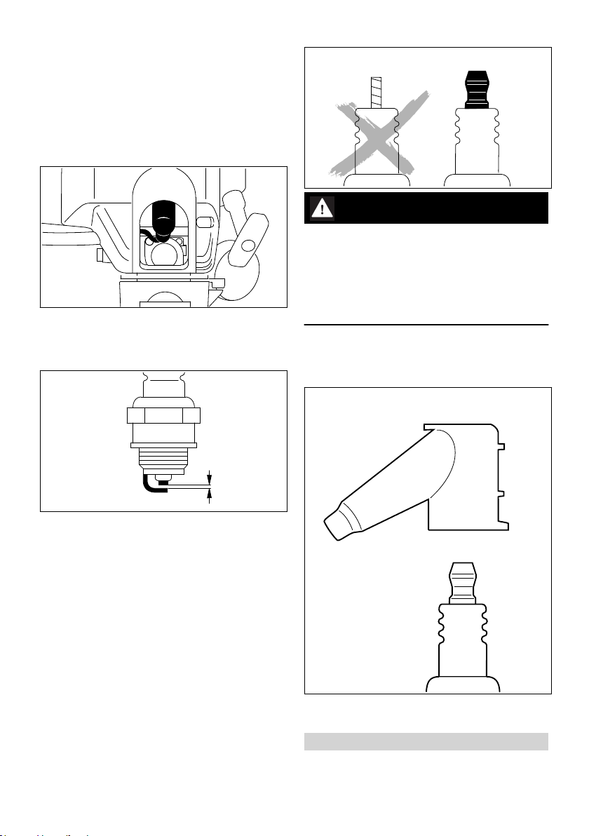
14.1 Desmontar la bujía
► Empujar el cursor del mando unificado
a STOP-0
ADVERTENCIA
En caso de no estar apretada la tuerca de cone‐
xión (1) o si esta falta, pueden producirse chis‐
pas. Si se trabaja en un entorno fácilmente infla‐
mable o explosivo se pueden provocar incendios
o explosiones. Las personas pueden sufrir lesio‐
nes graves o se pueden producir daños materia‐
► Retirar el enchufe de la bujía (1)
► Desenroscar la bujía
14.2 Examinar la bujía
les.
► Emplear bujías desparasitadas con tuerca de
conexión fija
14.3 Montar la bujía
► Limpiar la bujía si está sucia
► Comprobar la distancia entre electrodos (A) y
reajustarla si es necesario – para el valor de la
distancia, véase "Datos técnicos"
► Subsanar las causas del ensuciamiento de la
bujía
Causas posibles:
Exceso de aceite de motor en el combustible
–
Filtro de aire sucio
–
Condiciones de servicio desfavorables
–
16 0458-462-8721-B
► Enroscar la bujía (3) y presionar el enchufe (2)
de la misma firmemente sobre la bujía (3)
15 Guardar la máquina
En pausas de servicio, a partir de unos 30 días

389BA032 KN
393BA055 KN
16 Comprobación y mantenimiento por el usuario español
► Vaciar y limpiar el depósito de gasolina en un
lugar bien ventilado
► Gestionar los residuos del combustible según
las normas y los principios ecológicos
► Si se dispone de una bomba manual de com‐
bustible: presionarla al menos 5 veces antes
de arrancar el motor
► Arrancar el motor y dejarlo funcionar en ralentí
hasta que se pare
► Limpiar a fondo la máquina, especialmente el
filtro de aire
► Quitar la herramienta de trabajo, limpiarla y
revisarla; tratar las piezas de metal con aceite
protector
► Guardar la máquina en un lugar seco y
seguro. Protegerlo contra el uso por personas
ajenas (p. ej. por niños)
16 Comprobación y manteni‐
miento por el usuario
16.1 Cambiar el cabezal de aspira‐
Cambiar anualmente el cabezal de aspiración,
para ello:
► Vaciar el depósito de combustible
► Extraer del depósito el cabezal de aspiración
de combustible con un gancho y retirarlo del
tubo flexible
► Insertar un nuevo cabezal de aspiración en el
tubo flexible
► Volver a poner el cabezal de aspiración en el
depósito
17 Comprobación y manteni‐
miento por el distribuidor
especializado
17.1 Trabajos de mantenimiento
STIHL recomienda encargar los trabajos de
mantenimiento y las reparaciones siempre a un
distribuidor especializado STIHL.
17.2 Elemento antivibrador
ción de combustible
Entre la unidad motriz y el vástago hay montado
un elemento de goma para amortiguar las vibra‐
ciones. Encargar su comprobación en caso de
detectarse desgaste o vibraciones continua‐
mente elevadas.
0458-462-8721-B 17

español 18 Instrucciones de mantenimiento y conservación
18 Instrucciones de mantenimiento y conservación
Estos datos se refieren a condiciones de uso nor‐
males. Al tratarse de condiciones más complejas
(fuerte acumulación de polvo, etc.) y jornadas dia‐
rias más largas, deberán reducirse correspondien‐
temente los intervalos indicados.
Semanalmente
Tras llenar el depósito
Antes de comenzar el trabajo
Anualmente
Mensualmente
En caso de avería
En caso de daños
En caso necesario
Máquina completa Control visual (estado,
Empuñadura de mando Comprobación del fun‐
Filtro de aire Limpiar X X
Bomba manual de com‐
bustible
Cabezal de aspiración en
el depósito de combusti‐
ble
Depósito de combustible Limpiar X X
Carburador Comprobar el ralentí, la
Bujía Ajustar la distancia entre
Aberturas de aspiración
para aire de refrigeración
Rejilla parachispas1) en
el silenciador
Tornillos y tuercas acce‐
sibles (excepto tornillos
de ajuste)
Elementos antivibración Comprobar X X X
Rótulos adhesivos de
seguridad
estanqueidad)
Limpiar X
cionamiento
Sustituir X
Comprobar X
Llevar a un distribuidor
especializado2) para su
reparación
Comprobar
Sustituir
herramienta de trabajo
no deberá moverse
Ajustar el ralentí X
electrodos
Sustituir cada 100 horas
de servicio
Comprobación visual X
Limpiar X
Asegurarse de que se
ha montado
Comprobar o sustituir
Reapretar X
Llevar a un distribuidor
especializado2) para su
sustitución
Sustituir X
2)
Tras finalizar el trabajo o diariamente
X X
X X
X
X
X X X
X X
X
X
X
X
18 0458-462-8721-B

19 Minimizar el desgaste y evitar daños español
Estos datos se refieren a condiciones de uso nor‐
males. Al tratarse de condiciones más complejas
(fuerte acumulación de polvo, etc.) y jornadas dia‐
rias más largas, deberán reducirse correspondien‐
temente los intervalos indicados.
Semanalmente
Tras llenar el depósito
Antes de comenzar el trabajo
Anualmente
Mensualmente
En caso de avería
En caso de daños
En caso necesario
1)
Existente solo según en qué países
2)
STIHL recomienda distribuidores especializados STIHL
19 Minimizar el desgaste y
evitar daños
La observancia de las instrucciones de este
manual de instrucciones evita un desgaste exce‐
sivo y daños en la máquina.
El uso, mantenimiento y almacenamiento de la
máquina se han de realizar con el esmero des‐
crito en este manual de instrucciones.
Todos los daños originados por la inobservancia
de las instrucciones de seguridad manejo y man‐
tenimiento son responsabilidad del usuario
mismo. Ello rige en especial para:
Modificaciones del producto no autorizadas
–
por STIHL
El empleo de herramientas o accesorios no
–
autorizados o no apropiados para la máquina
o que sean de baja calidad
El empleo de la máquina para fines inapropia‐
–
dos
Empleo de la máquina en actos deportivos o
–
competiciones
Daños derivados de seguir utilizando la
–
máquina pese a la existencia de componentes
averiados
19.1 Trabajos de mantenimiento
Todos los trabajos especificados en el capítulo
"Instrucciones de mantenimiento y conservación"
se han de realizar con regularidad. Si no puede
efectuar estos trabajos de mantenimiento el
usuario mismo, deberá encargarlos a un distri‐
buidor especializado.
STIHL recomienda encargar los trabajos de
mantenimiento y las reparaciones siempre a un
distribuidor especializado STIHL. Los distribuido‐
Tras finalizar el trabajo o diariamente
res especializados STIHL siguen periódicamente
cursillos de instrucción y tienen a su disposición
las Informaciones técnicas.
De no efectuar a tiempo estos trabajos o si no se
realizan como es debido, pueden producirse
daños que serán responsabilidad del usuario
mismo. De ellos forman parte, entre otros:
Daños en el motor como consecuencia de de
–
un mantenimiento inoportuno o insuficiente (p.
ej. filtros de aire y combustible), ajuste erró‐
neo del carburador o limpieza insuficiente del
recorrido del aire de refrigeración (rendijas de
aspiración, aletas del cilindro)
Daños por corrosión y otros daños derivados
–
de un almacenamiento inadecuado
Daños en la máquina como consecuencia del
–
empleo de piezas de repuesto de mala calidad
19.2 Piezas de desgaste
Algunas piezas de la máquina están sometidas a
un desgaste normal aun cuando el uso sea el
apropiado y se han de sustituir oportunamente
en función del tipo y la duración de su utilización.
De ellas forman parte, entre otras:
Embrague
–
Filtro (para aire, combustible)
–
Dispositivo de arranque
–
Bujía
–
0458-462-8721-B 19

16
#
4
9
11
10
15
8
18
19
462BA005 KN
1
2
3
6
7
17
5
13
12
14
español 20 Componentes importantes
20 Componentes importantes
Potencia según ISO 8893: 0,95 kW (1,3 CV)
a 8500 rpm
Régimen de ralentí: 2800 rpm
Régimen de limitación de
10500 rpm
caudal (valor nominal):
21.2 Sistema de encendido
Encendido por magneto, de control electrónico
Bujía (desparasitada): Bosch WSR 6 F,NGK
BPMR 7 A
Distancia entre electrodos: 0,5 mm
21.3 Sistema de combustible
Carburador de membrana independiente de la
posición con bomba de combustible integrada
Cabida depósito de com‐
bustible:
440 cm3 (0,44 l)
21.4 Peso
1 Bomba manual de combustible
2 Palanca de la mariposa de arranque
3 Tornillos de ajuste del carburador
4 Empuñadura de arranque
5 Cierre del depósito de combustible
6 Depósito de combustible
7 Silenciador (según qué países, con rejilla
parachispas)
8 Argolla de porte
9 Cursor del mando unificado
10 Acelerador
11 Bloqueo del acelerador
12 Enchufe de la bujía
13 Tapa del filtro de aire
14 Apoyo de la máquina
15 Asidero tubular cerrado
16 Estribo
17 Vástago
18 Manguito de acoplamiento
19 Tornillo de muletilla
# Número de máquina
21 Datos técnicos
21.1 Motor
25,4 cm
3
Motor monocilíndrico de dos tiempos
Cilindrada:
Diámetro: 34 mm
Carrera: 28 mm
20 0458-462-8721-B
Sin combustible ni herramienta combinada
KM 85 R 3,9 kg
21.5 Valores de sonido y vibracio‐
nes
Para más detalles relativos al cumplimiento de la
pauta de la patronal sobre vibraciones
2002/44/CE, véase www.stihl.com/vib
21.5.1 Herramienta combinada
Para la ejecución véase "Herramientas combina‐
das admisibles"
Para determinar los valores de sonido y vibracio‐
nes, se tienen en cuenta el ralentí y el régimen
máximo nominal en las siguientes proporciones:
Con FCS‑KM, FCB‑KM, FS‑KM,
FSB-KM, FH‑KM y HT‑KM
Con HL‑KM 1 a 4
Con BF‑KM, BK-KM, KB‑KM,
KW‑KM, BG‑KM y SP‑KM
Los valores exactos de sonido y vibraciones
dependen de la herramienta combinada mon‐
tada y se describen en el manual de instruccio‐
nes de la herramienta combinada.
Nivel de intensidad sonora L
ISO 11201, ISO 22868
KM 85 R: 92 dB (A)... 98 dB (A)
Nivel de potencia sonora L
ISO 3744
KM 85 R: 106 dB (A)... 109 dB (A)
según
peq
según ISO 22868,
weq
1 a 1
1 a 6

000BA073 KN
22 Indicaciones para la reparación español
Valor de vibraciones a
ISO 20643, ISO 22867
Empuñadura izquierda
KM 85 R:
Empuñadura derecha
KM 85 R:
Para el nivel de intensidad sonora y el nivel de
potencia sonora, el factor K‑según RL 2006/42/
CE es = 2,5 dB(A); para el valor de vibraciones,
el factor K‑según RL 2006/42/CE es = 2,0 m/s².
según ISO 11789,
hv,eq
2,9 m/s2 ... 7,3 m/s
3,8 m/s2... 7,5 m/s
2
2
21.6 REACH
REACH designa una ordenanza CE para el
registro, evaluación y homologación de produc‐
tos químicos.
Información para cumplimentar la ordenanza
REACH (CE) núm. 1907/2006, véase
www.stihl.com/reach
21.7 Valor de emisiones de gases de escape
El valor de CO2 medido en el procedimiento de
sistema de homologación de la UE se indica en
www.stihl.com/co2
Indicar en los datos técnicos específicos del pro‐
ducto.
El valor medido de CO2 se ha determinado en
un motor representativo según un procedimiento
de comprobación normalizado en condiciones de
laboratorio y no representa una garantía explícita
o implícita de la potencia de un motor concreto.
Con el uso y mantenimiento previstos estipula‐
dos en este manual de instrucciones se cumplen
los requerimientos correspondientes de las emi‐
siones de gases de escape. En el caso de modi‐
ficaciones del motor se suspende el permiso de
funcionamiento.
22 Indicaciones para la repa‐
ración
Los usuarios de esta máquina sólo deberán rea‐
lizar trabajos de mantenimiento y conservación
que estén especificados en este manual de ins‐
trucciones. Las reparaciones de mayor alcance
las deberán realizar únicamente distribuidores
especializados.
STIHL recomienda encargar los trabajos de
mantenimiento y las reparaciones siempre a un
distribuidor especializado STIHL. Los distribuido‐
0458-462-8721-B 21
res especializados STIHL siguen periódicamente
cursillos de instrucción y tienen a su disposición
las informaciones técnicas.
En casos de reparación, montar únicamente pie‐
zas de repuesto autorizadas por STIHL para
esta máquina o piezas técnicamente equivalen‐
tes. Emplear sólo repuestos de gran calidad. De
no hacerlo, existe el peligro de que se produz‐
can accidentes o daños en la máquina.
STIHL recomienda emplear piezas de repuesto
originales STIHL.
Las piezas originales STlHL se reconocen por el
número de pieza de repuesto STlHL, por el logo‐
tipo { y, dado el caso, el anagrama de
repuestos STlHL K (en piezas pequeñas,
puede encontrarse este anagrama también
solo).
23 Gestión de residuos
La administración municipal o los distribuidores
especializados STIHL ofrecen información sobre
la gestión de residuos.
Una gestión indebida puede dañar la salud y el
medio ambiente.
► Llevar los productos STIHL incluido el emba‐
laje a un punto de recogida adecuado para el
reciclado con arreglo a las prescripciones
locales.
► No echarlos a la basura doméstica.
24 Declaración de conformi‐
dad UE
ANDREAS STIHL AG & Co. KG
Badstr. 115
D-71336 Waiblingen
Alemania
declara, como único responsable, que
Tipo: Motor universal
Marca: STIHL
Modelo: KM 85 R

English
Identificación de serie: 4137
Cilindrada:
cumple las disposiciones pertinentes de las
directrices 2011/65/UE, 2006/42/CE y
2014/30/UE y que se ha desarrollado y fabricado
en cada caso conforme a las versiones de las
normas siguientes vigentes en la fecha de pro‐
ducción:
EN ISO 12100, EN 55012, EN 61000‑6‑1 (en
combinación con las llamadas herramientas
combinadas BF‑KM, BK-KM, BG‑KM, FCB‑KM,
FCS‑KM, FH‑KM, FS‑KM, FSB‑KM, HL‑KM,
HT‑KM, KB‑KM, KW‑KM y SP‑KM)
El motor universal descrito se deberá utilizar úni‐
camente en combinación con las herramientas
combinadas autorizadas por STIHL para este
motor.
Conservación de la documentación técnica:
ANDREAS STIHL AG & Co. KG
Produktzulassung
El año de construcción y el número de máquina
están indicados en la misma.
Waiblingen, 03/02/2020
ANDREAS STIHL AG & Co. KG
Atentamente,
25,4 cm
3
10 Operating Instructions...............................32
11 Cleaning the Air Filter............................... 32
12 Adjusting the Carburetor........................... 33
13 Spark Arresting Screen in Muffler............. 34
14 Spark Plug................................................ 35
15 Storing the Machine.................................. 35
16 Inspection and Maintenance by User........36
17 Inspections and Maintenance by Dealer...36
18 Maintenance and Care..............................37
19 Minimize Wear and Avoid Damage...........38
20 Main Parts.................................................38
21 Specifications............................................39
22 Maintenance and Repairs......................... 39
23 Disposal.................................................... 40
24 EC Declaration of Conformity................... 40
Dear Customer,
Thank you for choosing a quality engineered
STIHL product.
It has been built using modern production techni‐
ques and comprehensive quality assurance.
Every effort has been made to ensure your satis‐
faction and trouble-free use of the product.
Please contact your dealer or our sales company
if you have any queries concerning this product.
Your
Original Instruction Manual
0000007890_006_GB
Printed on chlorine-free paper
Printing inks contain vegetable oils, paper can be recycled.
Dr. Nikolas Stihl
1 KombiSystem
Dr. Jürgen Hoffmann
Jefe de departamento homologación y regula‐
ción de producto
Contents
1
KombiSystem............................................22
2 Guide to Using this Manual.......................22
3 Safety Precautions and Working Techni‐
ques.......................................................... 23
4 Approved KombiTools...............................26
5 Mounting the Loop Handle........................27
6 Adjusting the Throttle Cable......................28
7 Fuel........................................................... 28
8 Fueling...................................................... 29
9 Starting / Stopping the Engine.................. 30
22 0458-462-8721-B
In the STIHL KombiSystem a number of different
KombiEngines and KombiTools can be com‐
bined to produce a power tool. In this instruction
manual the functional unit formed by the Kom‐
biEngine and KombiTool is referred to as the
power tool.
Therefore, the separate instruction manuals for
the KombiEngine and KombiTool should be used
together for the power tool.
Always read and and make sure you understand
both instruction manuals before using your
power tool for the first time and keep them in a
safe place for future reference.
2 Guide to Using this Manual
2.1 Pictograms
All the pictograms attached to the machine are
shown and explained in this manual.
© ANDREAS STIHL AG & Co. KG 2022
0458-462-8721-B. VA0.M21.

3 Safety Precautions and Working Techniques English
2.2 Symbols in text
WARNING
Warning where there is a risk of an accident or
personal injury or serious damage to property.
NOTICE
Caution where there is a risk of damaging the
machine or its individual components.
2.3 Engineering improvements
STIHL's philosophy is to continually improve all
of its products. For this reason we may modify
the design, engineering and appearance of our
products periodically.
Therefore, some changes, modifications and
improvements may not be covered in this man‐
ual.
3 Safety Precautions and
Working Techniques
Special safety precautions must be
observed when operating a power
tool.
Both user manuals (KombiEngine
and KombiTool) must be read
through attentively before using the
unit for the first time and kept in a
safe place for future reference. Noncompliance with the user manuals
may cause serious or even fatal
injury.
Observe all applicable local safety regulations,
e.g. by trade organizations, social insurance
institutions, labor safety authorities etc.
If you have never used a power tool before:
Have your dealer or other experienced user
show you how to operate your machine – or
attend a special course to learn how to operate
it.
Minors should never be allowed to use the
machine – except for apprentices over the age of
16 when working under supervision.
Children, animals and onlookers must not be
allowed near the machine.
When not using the machine, it must be laid
down in such a way that it does not endanger
anyone. Ensure that the machine cannot be
used without authorization.
The user is responsible for accidents or risks
involving third parties or their property.
The machine should only be provided or loaned
to people familiar with this model and its opera‐
tion. The KombiEngine and KombiTool user
manuals should always be handed over with the
machine.
The use of noise emitting power tools may be
restricted to certain times by national or local
regulations.
Anyone operating the machine must be well res‐
ted, in good physical health and in good mental
condition.
If you have any condition that might be aggrava‐
ted by strenuous work, check with your doctor
before operating a machine.
Persons with pacemakers only: The ignition sys‐
tem of your power tool produces an electromag‐
netic field of a very low intensity. This field may
interfere with some pacemakers. STIHL recom‐
mends that persons with pacemakers consult
their physician and the pacemaker manufacturer
to reduce any health risk.
Anyone who has consumed alcohol, medications
or drugs that impair their ability to react must not
operate a power tool.
Use your power tool only for the applications
described in the User Manual of the KombiTool
you are using.
The machine must not be used for any other pur‐
poses – risk of accident!
Do not operate the KombiEngine without a prop‐
erly mounted KombiTool since this may result in
damage to the machine.
Only use KombiTools and accessories that are
explicitly approved for this power tool by STIHL
or are technically identical. It is important that
you read the chapter on "Approved KombiTools".
If you have any questions in this respect, consult
your dealer. Use only high-quality parts and
accessories. in order to avoid the risk of acci‐
dents and damage to the machine.
STIHL recommends the use of genuine STIHL
tools and accessories. They are specifically
designed to match the product and meet your
performance requirements.
Never attempt to modify your power tool in any
way since this may increase the risk of personal
injury. STIHL excludes all liability for personal
0458-462-8721-B 23

English 3 Safety Precautions and Working Techniques
injury and damage to property caused while
using unauthorized attachments.
Do not use a high pressure washer to clean your
power tool. The powerful jet of water may dam‐
age parts of the power tool.
3.1 Clothing and Equipment
Wear proper protective clothing and equipment.
Do not wear clothing which could
become trapped in wood, brush or
moving parts of the machine. Do not
wear a scarf, necktie or jewelry. Tie
up and confine long hair above your
shoulders.
See also notes on "Clothing and Equipment" in
the instruction manual of the KombiTool you are
using.
3.2 Transporting the machine
Always stop the engine.
In vehicles: Secure the power tool against tipping
over, damage and fuel leakage.
See also notes on "Transporting the Machine" in
the User Manual of the KombiTool you are using.
3.3 Refueling
Gasoline is highly flammable – keep
away from fire or flame – do not spill
any fuel – no smoking.
Always shut off the engine before refueling.
Do not fuel a hot engine – fuel may spill and
cause a fire.
Open the fuel cap carefully to allow any pressure
build-up in the tank to release slowly and to pre‐
vent fuel spraying out.
Only refuel the machine in a well ventilated
place. If fuel has been spilled, immediately clean
the machine – do not allow your clothes to be
splashed with fuel. If that happens, change your
clothes at once.
This helps reduce the risk of unit vibrations caus‐
ing an incorrectly tightened fuel cap to loosen or
come off and spill quantities of fuel.
Check for leaks. Do not start the engine if there
is a fuel leak – serious or fatal burns could result!
3.4 Before starting
Check that your power tool is properly assem‐
bled and in good condition – refer to appropriate
chapters in the User Manuals:
–
–
–
–
–
–
–
–
The power tool must only be operated when it is
in good operating condition – Risk of accident!
To prepare for an emergency when using har‐
nesses: Practice quickly removing and setting
down the power tool. To avoid damage, do not
throw the power tool to the ground when practic‐
ing.
See also notes on "Before Starting" in the User
Manual of the KombiTool you are using.
3.5 Starting the Engine
Start the engine at least 3 meters from the refuel‐
ing spot and only outdoors.
After refueling, close the fuel cap as
tightly as possible.
Check the fuel system for leaks, especially the
visible parts, e. g., fuel cap, hose connections,
manual fuel pump (only in machines with a
manual fuel pump). In case of leakage and
damage, do not start the engine – risk of fire!
Have the machine serviced by a dealer before
using it
Use only an approved combination of cutting
attachment, deflector, handle and harness. All
parts must be assembled properly and
securely
Slide control / stop switch must move easily to
STOP or 0
Smooth action of throttle trigger lockout and
throttle trigger – the throttle trigger must return
automatically to the idle position
Check that the spark plug boot is secure – a
loose boot may cause sparking that could
ignite combustible fumes and cause a fire!
Never attempt to modify the controls or safety
devices.
Keep the handles dry and clean – free from oil
and dirt – this is important for safe control of
the machine
Adjust harness and handle to suit your height
and reach.
24 0458-462-8721-B

002BA273 KN
3 Safety Precautions and Working Techniques English
Place the unit on a flat surface in an open area.
Make sure you have good balance and secure
footing. Hold the unit securely. The work tool
must be clear of the ground and all other
obstructions because it may begin to run when
the engine starts.
To reduce the risk of injury, avoid contact with
the work tool.
Do not drop-start the power tool – start the
engine as described in the User Manual. Note
that the attachment continues to run for a short
period after you let go of the throttle trigger – fly‐
wheel effect.
Check idle speed setting: The attachment must
be stationary when the engine is idling with the
throttle trigger released.
Keep easily combustible materials (e.g., wood
chips, bark, dry grass, fuel) away from hot
exhaust gases and hot muffler surfaces – risk of
fire!
See also notes on "Starting / Stopping the
Engine" in the User Manual of the KombiTool
you are using.
3.6 Holding and Controlling the
Power Tool
Always hold the power tool firmly with both
hands on the handles.
Make sure you always have a firm and secure
footing.
Left hand on loop handle, right hand on control
handle, even if you are left-handed.
3.7 While Working
In the event of impending danger or in an emer‐
gency, switch off the engine immediately. Move
the slide control/stop switch to STOP or 0.
The correct engine idle speed is important to
ensure that the work tool stops moving when you
let go of the throttle trigger. If the working tool
continues to move when the engine is idling,
have your dealer check the machine and make
proper adjustments or repairs. Check and correct
the idle speed setting at regular intervals. STIHL
recommends you have this work done by a
STIHL servicing dealer.
Be particularly alert and cautious when wearing
hearing protection because your ability to hear
warnings (shouts, alarms, etc.) is restricted.
Take breaks when you start getting tired or feel‐
ing fatigue – risk of accidents!
Work calmly and carefully – in daylight conditions
and only when visibility is good. Proceed with
caution, do not put others in danger.
Use your power tool only for those applications
described in the KombiTool User Manual.
The power tool generates toxic
exhaust fumes as soon as the engine
is running. These gases may be odor‐
less and invisible and may contain
unburned hydrocarbons and ben‐
zene. Never run the engine indoors or
in poorly ventilated locations, even if
your model is equipped with a cata‐
lytic converter.
To reduce the risk of serious or fatal injury from
breathing toxic fumes, ensure proper ventilation
when working in trenches, hollows or other con‐
fined locations.
Stop work immediately if you start suffering from
nausea, headaches, impaired vision (e.g. your
field of vision gets smaller), impaired hearing,
dizziness, or impaired concentration – these
symptoms may possibly be the result of too-high
exhaust gas concentration – Risk of accidents!
Operate your power tool so that it produces a
minimum of noise and emissions – do not run the
engine unnecessarily, accelerate the engine only
when working.
To reduce the risk of fire, do not smoke while
operating or standing near your power tool. Com‐
bustible fuel vapor may escape from the fuel sys‐
tem.
Dust, fumes and smoke produced while working
may be hazardous to health. Wear a suitable
respirator in dusty or smoky conditions.
If your power tool is subjected to unusually high
loads for which it was not designed (e.g., heavy
impact or a fall), always check that it is in good
condition before continuing work. See also
"Before Starting". Check in particular that the fuel
0458-462-8721-B 25

English 4 Approved KombiTools
system has no leaks and the safety equipment is
fully operative. Never use a power tool that is no
longer safe to operate. In case of doubt, contact
a dealer.
Do not operate your power tool in the starting
throttle position – engine speed cannot be con‐
trolled in this position.
Before leaving the power tool unattended: Shut
off the engine.
To reduce the risk of injury, always shut off the
engine before changing the KombiTool or work
tool.
3.8 Vibrations
Prolonged use of the power tool may result in
vibration-induced circulation problems in the
hands (whitefinger disease).
No general recommendation can be given for the
length of usage because it depends on several
factors.
The period of usage is prolonged by:
Hand protection (wearing warm gloves)
–
Work breaks
–
The period of usage is shortened by:
Any personal tendency to suffer from poor cir‐
–
culation (symptoms: frequently cold fingers,
tingling sensations).
Low outside temperatures.
–
The force with which the handles are held (a
–
tight grip restricts circulation).
Continual and regular users should monitor
closely the condition of their hands and fingers. If
any of the above symptoms appear (e.g. tingling
sensation in fingers), seek medical advice.
3.9 Maintenance and Repairs
Service the machine regularly. Do not attempt
any maintenance or repair work not described in
the instruction manual. Have all other work per‐
formed by a servicing dealer.
STIHL recommends that you have servicing and
repair work carried out exclusively by an author‐
ized STIHL servicing dealer. STIHL dealers are
regularly given the opportunity to attend training
courses and are supplied with the necessary
technical information.
Only use high-quality replacement parts in order
to avoid the risk of accidents and damage to the
machine. If you have any questions in this
respect, consult a servicing dealer.
STIHL recommends the use of original STIHL
replacement parts. They are specifically
designed to match your model and meet your
performance requirements.
To reduce the risk of injury, always shut off the
engine before carrying out any maintenance or
repairs or cleaning the machine. – Exception:
Carburetor and idle speed adjustments.
Do not turn the engine over on the starter with
the spark plug boot or spark plug removed
unless the slide control / stop switch is on STOP
or 0 since there is otherwise a risk of fire from
uncontained sparking.
To reduce the risk of fire, do not service or store
your machine near open flames.
Check the fuel filler cap for leaks at regular inter‐
vals.
Use only a spark plug of the type approved by
STIHL and make sure it is in good condition –
see "Specifications".
Inspect the ignition lead (insulation in good con‐
dition, secure connection).
Check the condition of the muffler.
To reduce the risk of fire and damage to hearing,
do not operate your machine if the muffler is
damaged or missing. –
Do not touch a hot muffler since burn injury will
result.
Vibration behavior is influenced by the condition
of the AV elements – check the AV elements at
regular intervals.
4 Approved KombiTools
The following STIHL KombiTools may be
attached to the KombiEngine:
KombiTool
FS‑KM Scythe with mowing head
1)
FS‑KM
FSB‑KM Scythe with mowing head
HL‑KM 145° Long reach hedge trim‐
HL‑KM 0° Long-reach hedge trim‐
FH‑KM 145°
BG‑KM Blower
HT‑KM
Intended use
Scythe with grass cutting
blade
mer, adjustable
mer
Scrub cutter
Pole pruner
1)
The included barrier bar on the loop handle must be used - see also "Mounting the Loop Handle”
26 0458-462-8721-B

2
002BA098 KN
1
1
5
4
002BA099 KN
2
3
6
7
5 Mounting the Loop Handle English
KombiTool
BF‑KM Cultivator
FCB‑KM Edger
FCS‑KM Edger
SP‑KM Harvesters
KB‑KM Bristle brush
KW-KM Sweeper drum assembly
Intended use
5 Mounting the Loop Handle
A barrier bar is supplied with the machine. Attach
the barrier bar to the loop handle.
► Insert the clamp (3) in the loop handle (4) and
position them together on the shaft (5)
► Position clamp (6)
► Position barrier bar (2) – note position!
► Line up the holes
► Insert bolts (7) in the holes – and screw them
into the barrier bar as far as possible
► Insert square nuts (1) in the barrier bar (2) –
the holes must line up
1)
The included barrier bar on the loop handle must be used - see also "Mounting the Loop Handle”
0458-462-8721-B 27

A
9
8
4
002BA353 KN
002BA163 KN
2
1
002BA161 KN
English
► Press down the trigger lockout (1) and
squeeze the throttle trigger (2) (full throttle
position) – this sets the throttle cable correctly.
6 Adjusting the Throttle Cable
7 Fuel
The engine requires a mixture of gasoline and
engine oil.
WARNING
Avoid direct skin contact with fuel and breathing
in of gasoline fumes.
► Fit the loop handle (4) at a distance of (A)
approx. 20 cm (8 in) forward of the control
handle (8)
► Orient the loop handle
► Tighten the bolts – lock the nuts if necessary
The sleeve (9) is present depending on the coun‐
try and must be located between the loop handle
and control handle.
Always leave the barrier bar attached.
6 Adjusting the Throttle
Cable
A properly adjusted throttle cable is the precondi‐
tion for correct operation in the starting throttle,
idle and full throttle positions.
Adjust the throttle cable only when the machine
is completely and properly assembled.
7.1 STIHL MotoMix
STIHL recommends using STIHL MotoMix. This
pre-blended fuel is free of benzene and lead, is
distinguished by a high octane rating, and
always provides the proper mixing ratio.
STIHL MotoMix uses STIHL HP Ultra two-stroke
engine oil for optimum engine life.
MotoMix is not available in all markets.
7.2 Mixing fuel
NOTICE
Unsuitable fuels or a mixing ratio that deviates
from the specification can lead to severe engine
damage. The engine, seals, fuel lines and fuel
tank may be damaged if low-quality gasoline or
engine oil is used.
7.2.1 Gasoline
► Use a suitable tool to push the slide to the end
of the slot (see illustration).
28 0458-462-8721-B
Use only high-quality gasoline with an octane rat‐
ing of at least 90 ROC – leaded or unleaded.
Gasoline with an alcohol component exceeding
10% can cause impaired engine performance in
engines with manually adjustable carburetors
and thus should not be used in these engines.
Engines with M-Tronic deliver full engine per‐
formance using gasoline with an alcohol compo‐
nent of up to 27% (E27).

389BA031 KN
8 Fueling English
7.2.2 Engine oil
If you mix the fuel yourself, use only STIHL two-
stroke engine oil or another high-performance
engine oil classified as JASO FB, JASO FC,
JASO FD, ISO-L-EGB, ISO-L-EGC or ISO-LEGD.
STIHL specifies STIHL HP Ultra two-stroke
engine oil or an equivalent high-performance
engine oil in order to maintain emission limits
over the machine’s service life.
7.2.3 Mixing ratio
with STIHL two-stroke engine oil 1:50; 1:50 =
1 part oil + 50 parts gasoline
7.2.4 Examples
Quantity of gaso‐
line
Liters Liters (ml)
1 0.02 (20)
5 0.10 (100)
10 0.20 (200)
15 0.30 (300)
20 0.40 (400)
25 0.50 (500)
► Pour oil into an approved safety fuel canister
first, then add gasoline and mix thoroughly
STIHL two-stroke
engine oil 1:50
8 Fueling
8.1 Preparations
7.3 Storing fuel mixture
Store in approved safety fuel canisters only in a
dry, cool and secure place protected against light
and sunlight.
Fuel mixture deteriorates with age – mix only as
much as needed for a few weeks. Do not store
fuel mixture for longer than 30 days. The fuel
mixture can become unusable more quickly if
exposed to light, sunlight or low or high tempera‐
tures.
STIHL MotoMix however can be stored for up to
5 years without any problems.
► Shake the canister containing the fuel mixture
thoroughly before refueling
► Before fueling, clean the filler cap and the area
around it to ensure that no dirt falls into the
tank.
► Position the machine so that the tank cap
faces up.
8.2 Filling Up with Fuel
Take care not to spill fuel while fueling and do
not overfill the tank. STIHL recommends you use
the STIHL filler nozzle for fuel (special acces‐
sory).
► Open the tank cap.
► Fill up with fuel.
WARNING
Pressure may have built up in the canister –
open it carefully.
► The fuel tank and the canister in which fuel
mixture is stored should be cleaned thoroughly
from time to time
Residual fuel and the liquid used for cleaning
must be disposed of in accordance with regula‐
tions and without harming the environment!
0458-462-8721-B 29

3
STOP
2
5
6
4
7
002BA181 KN
START
STOP-
1
393BA017 KN
8
8
393BA018 KN
9
552BA014 KN
English 9 Starting / Stopping the Engine
WARNING
After fueling, tighten down the filler cap as
securely as possible by hand.
9 Starting / Stopping the
Engine
9.2 Starting
► Press down the trigger lockout lever and
squeeze the throttle trigger
► and hold them in that position.
► Move the slide control to START and hold it
there.
► Now release the throttle trigger, slide control
and trigger lockout in that order. This is the
starting throttle position.
9.1 Controls
► Set the choke lever (8) to:
if the engine is cold
g
for warm start – also use this position if the
e
engine has been running but is still cold.
1 Throttle trigger lockout
2 Throttle trigger
3 Slide control
9.1.1 Positions of slide control
4 STOP-0 – engine off – ignition is switched off
5
F – normal run position – the engine is running
or can start
6 START – ignition is switched on – the engine
can start
9.1.2 Symbol on slide control
7
h – stop symbol and arrow. To stop the
engine, push the slide control in the direction
of the arrow on the stop symbol (h) to
STOP-0.
► Press the manual fuel pump bulb (9) at least
five times – even if the bulb is filled with fuel.
9.2.1 Cranking
30 0458-462-8721-B

552BA015 KN
552BA016 KN
9 Starting / Stopping the Engine English
9.2.3 As soon as the engine runs
► Blip the throttle trigger immediately. The slide
control moves to the normal run position F –
and the engine settles down to idle speed.
WARNING
Make sure the carburetor is correctly adjusted.
The working tool must not move when the engine
is idling.
► Place the power tool on the ground so that it
rests on the machine support: Check that the
working tool is not touching the ground or any
other obstacles – see also "Starting / Stopping
the Engine" in the KombiTool instruction man‐
ual.
► Make sure you have a safe and secure foot‐
ing.
► Hold the unit with your left hand and press it
down firmly – your thumb should be under the
fan housing.
NOTICE
Do not stand or kneel on the drive tube.
► Hold the starter grip with your right hand.
► Pull the starter grip slowly until you feel it
engage and then give it a brisk strong pull.
NOTICE
Do not pull out the starter rope all the way – it
might otherwise break.
► Do not let the starter grip snap back. Guide it
slowly back into the housing so that the starter
rope can rewind properly.
► Continue cranking.
9.2.2 When engine begins to fire
►
Set the choke lever to e.
► continue cranking.
Your machine is now ready for operation.
9.3 Stopping the Engine
► Push the slide control in the direction of the
arrow on the stop symbol (h) to STOP-0.
9.4 At very low outside tempera‐
tures
As soon as the engine runs:
► Blip the throttle trigger to disengage the start‐
ing throttle position. The slide control moves to
the normal run position F – and the engine set‐
tles down to idle speed.
► Open the throttle slightly.
► Warm up the engine for a short period.
9.5 If the engine does not start
Choke Lever
If you did not move the choke lever to e quickly
enough after the engine began to fire, the com‐
bustion chamber is flooded.
►
Set the choke lever to e .
► Set the slide control, interlock lever and throt‐
tle trigger to the starting throttle position.
► Start the engine by pulling the starter rope
briskly – 10 to 20 pulls may be necessary.
9.5.1 If the engine still does not start
► Move the slide control to
► Remove the spark plug – see "Spark Plug".
► Dry the spark plug.
► Crank the engine several times with the starter
to clear the combustion chamber.
► Refit the spark plug – see "Spark Plug".
► Move the slide control to START.
►
Set the choke lever to e – even if the engine
is cold.
► Now start the engine.
9.5.2 Throttle cable adjustment
► Check adjustment of throttle cable – see chap‐
ter on "Adjusting the Throttle Cable".
STOP-0.
0458-462-8721-B 31

355BA014 KN
2
1
3
392BA046 KN
2
English 10 Operating Instructions
9.5.3 Fuel tank run until completely dry
► After refueling, press the manual fuel pump
bulb at least five times – even if the bulb is fil‐
led with fuel.
► Set the choke lever to suit the engine temper‐
ature.
► Now start the engine.
On the clip-on filter cover:
10 Operating Instructions
10.1 During break-in period
A factory-new machine should not be run at high
revs (full throttle off load) for the first three tank
fillings. This avoids unnecessary high loads dur‐
ing the break-in period. As all moving parts have
to bed in during the break-in period, the frictional
resistances in the engine are greater during this
period. The engine develops its maximum power
after about 5 to 15 tank fillings.
10.2 During Operation
After a long period of full throttle operation, allow
the engine to run for a short while at idle speed
so that engine heat can be dissipated by the flow
of cooling air. This protects engine-mounted
components (ignition, carburetor) from thermal
overload.
10.3 After Finishing Work
Storing for a short period: Wait for the engine to
cool down. Empty the fuel tank and keep the
machine in a dry place, well away from sources
of ignition, until you need it again. For longer outof-service periods – see "Storing the Machine".
► Press in the tab (1) and swing the filter
cover (2) away.
On the screw-mounted filter cover:
11 Cleaning the Air Filter
Dirty air filters reduce engine power, increase
fuel consumption and make starting more diffi‐
cult.
Your power tool comes standard with either a
clip-on or screw-mounted filter cover.
11.1 If there is a noticeable loss of
►
Set the choke lever to g.
engine power
► Loosen the screw (3) and remove the filter
cover (2).
32 0458-462-8721-B
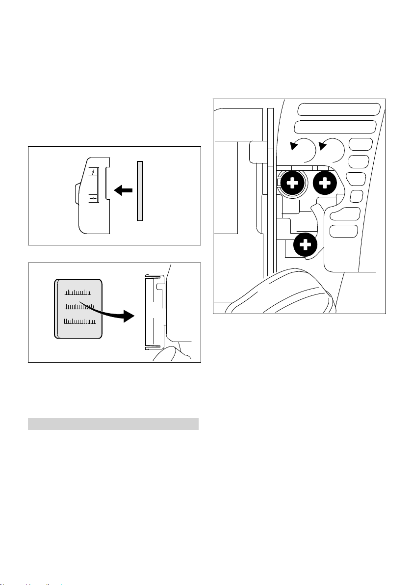
2
4
392BA047 KN
5
6
392BA048 KN
265BA024 KN
LA
HL
1
3 / 4
12 Adjusting the Carburetor English
On both versions:
► Clean away loose dirt from around the filter.
► Remove the foam and felt filter elements.
► Wash the foam element in a clean, non-flam‐
mable solution (e.g. warm soapy water) and
then dry.
► Fit a new felt element – do not wash. As a
temporary measure you can knock it out on
the palm of your hand or blow it out with com‐
pressed air.
Replace any damaged parts.
► Fit the foam filter element (4) in the filter cover.
► Check the air filter and clean or replace as
necessary.
► Check that the throttle cable is properly adjus‐
ted – readjust if necessary – see chapter on
"Adjusting the Throttle Cable".
► Check the spark arresting screen (not in all
versions) and clean or replace as necessary.
► Turn high speed screw (H) counterclockwise
as far as stop (no more than 3/4 turn).
► Turn the low speed screw (L) carefully clock‐
wise as far as stop, then turn it back 1 turn.
► Start and warm up the engine if necessary.
► Place the felt element (5) (lettering facing
inwards) in the filter housing (6).
► Fit the filter cover.
► Clip the filter cover in position or tighten down
the screw firmly.
12 Adjusting the Carburetor
The carburetor comes from the factory with a
standard setting.
This setting provides an optimum fuel-air mixture
under most operating conditions.
With this carburetor it is only possible to adjust
the high speed and low speed screws within fine
limits.
12.1 Standard Setting
► Shut odd the engine.
► Mount the KombiTool complete with working
tool or cutting attachment.
0458-462-8721-B 33
► Adjust idle speed with the idle speed
screw (LA) so that the cutting attachment does
not move.
12.2 Fine Tuning
A slight correction of the setting of the high
speed screw (H) may be necessary if engine
power is not satisfactory when operating at high
altitude, sea level or after changing the working
tool.
Rule of thumb:
Turn the high speed screw (H) about one quarter
turn for every 1000m change in altitude.
Conditions for adjustment
► Carry out standard setting on low speed
screw (L).
► Warm up the engine for about 3 minutes.
► Open the throttle wide.

392BA035 KN
English 13 Spark Arresting Screen in Muffler
12.2.1 At high altitude
► Turn the high speed screw (H) clockwise
(leaner), no further than stop, until there is no
further noticeable increase in engine speed.
12.2.2 At sea level
► Turn the high speed screw (H) counterclock‐
wise (richer), no further than stop, until there is
no further noticeable increase in engine
speed.
It is possible that maximum engine speed may
be reached with the standard setting in each
case.
12.3 Adjusting Idle Speed
It is usually necessary to change the setting of
the idle speed screw (LA) after every correction
to the low speed screw (L).
► Warm up the engine for about 3 minutes.
12.3.1 Engine stops while idling
► Turn the idle speed screw (LA) slowly clock‐
wise until the engine runs smoothly – the
working tool or cutting attachment must not
move.
12.3.2 Cutting attachment runs when engine
is idling
► Turn the idle speed screw (LA) counterclock‐
wise until the working tool or cutting attach‐
ment stops moving and then rotate the screw
another 1/2 to 1 turn in the same direction.
13 Spark Arresting Screen in
Muffler
In some countries, the mufflers are equipped
with a spark arresting screen.
If engine power deteriorates, check the spark
arresting screen in the muffler.
WARNING
To reduce the risk of fire caused by hot particles
escaping from the machine, never operate the
machine without a spark arresting screen or with
the spark arresting screen damaged. Do not
modify the muffler or spark arresting screen.
NOTICE
According to the law or regulations in some
countries or states, certain operations may only
be carried out if a properly serviced spark arrest‐
ing screen is provided.
WARNING
If the working tool or cutting attachment contin‐
ues to run when the engine is idling, have your
machine checked and repaired by your servicing
dealer.
12.3.3 Erratic idling behavior, engine stops
Idle setting is too lean
► Idle setting is too lean: Rotate the low speed
12.3.4 Erratic idling behavior
Idle setting is too rich
► Rotate the low speed screw (L) about 1/4 turn
34 0458-462-8721-B
even though setting of LA‑screw has
been corrected, poor acceleration
screw (L) about 1/4 turn counterclockwise until
the engine runs and accelerates smoothly.
clockwise until the engine runs and acceler‐
ates smoothly.
► Lift the spark arresting screen and pull it out.
► Clean the spark arresting screen. If the screen
is damaged or heavily carbonized, fit a new
one
► Refit the spark arresting screen.

1
393BA053 KN
000BA039 KN
A
1
000BA045 KN
3
000BA050 KN
2
14 Spark Plug English
14 Spark Plug
► If the engine is down on power, difficult to start
or runs poorly at idle speed, first check the
spark plug.
► Fit a new spark plug after about 100 operating
hours – or sooner if the electrodes are badly
eroded. Install only suppressed spark plugs of
the type approved by STIHL – see "Specifica‐
tions".
14.1 Removing the Spark Plug
► Move the slide control to STOP-0.
► Pull off the spark plug boot (1).
► Unscrew the spark plug.
14.2 Checking the Spark Plug
WARNING
Arcing may occur if the adapter nut (1) is loose
or missing. Working in an easily combustible or
explosive atmosphere may cause a fire or an
explosion. This can result result in serious inju‐
ries or damage to property.
► Use resistor type spark plugs with a properly
tightened adapter nut.
14.3 Installing the Spark Plug
► Clean dirty spark plug.
► Check electrode gap (A) and readjust if neces‐
sary – see "Specifications".
► Rectify the problems which have caused foul‐
ing of the spark plug.
Possible causes are:
Too much oil in fuel mix.
–
Dirty air filter.
–
Unfavorable running conditions.
–
0458-462-8721-B 35
► Screw the spark plug (3) into the cylinder and
fit the boot (2) (press it down firmly).
15 Storing the Machine
For periods of 30 days or longer
► Drain and clean the fuel tank in a well ventila‐
ted area.
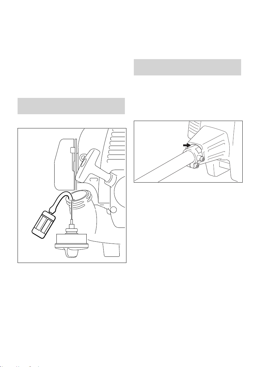
389BA032 KN
393BA055 KN
English 16 Inspection and Maintenance by User
► Dispose of fuel properly in accordance with
local environmental requirements.
► If a manual fuel pump is fitted: Press the man‐
ual fuel pump at least 5 times.
► Start the engine and run it at idling speed until
it stops.
► Thoroughly clean the machine – pay special
attention to the air filter.
► Remove, clean and check the attachment.
Coat metal parts with corrosion inhibiting oil.
► Store the machine in a dry and secure location
Keep out of the reach of children and other
unauthorized persons.
16 Inspection and Mainte‐
nance by User
Change the fuel pickup body every year:
► Drain the fuel tank.
► Use a hook to pull the fuel pickup body out of
the tank and take it off the hose.
► Push the new pickup body into the hose.
► Place the pickup body in the tank.
17 Inspections and Mainte‐
nance by Dealer
17.1 Maintenance Work
STIHL recommends that you have servicing and
repair work carried out exclusively by an author‐
ized STIHL servicing dealer.
17.2 Antivibration Element
16.1 Changing the Fuel Pickup Body
A vibration-absorbing rubber element is installed
between the powerhead and the drive tube.
Have it checked if there are signs of wear or a
noticeable increase in vibration levels.
36 0458-462-8721-B

18 Maintenance and Care English
18 Maintenance and Care
The following intervals apply for normal operating
conditions. The specified intervals must be short‐
ened accordingly when working for longer than nor‐
mal or under difficult cutting conditions (extensive
dust, etc.).
Weekly
Before starting work
Whenever tank is refilled
Monthly
If faulty
Annually
If damaged
As required
Complete machine Visual inspection (condi‐
X X
tion, leaks)
Clean X
Control handle Function test X X
Air filter Clean X X
replace X
Manual fuel pump check X
At the end of work and/or daily
Fuel pickup body in fuel
tank
Have repaired by a spe‐
cialist dealer
2)
check
replace
X
X
X X X
Fuel tank Clean X X
Carburetor Check idle adjustment,
X X
the work tool must not
turn
Adjust idle speed X
Spark plug Set electrode gap X
Replace after every 100
hours of operation
Cooling air intakes Visual inspection X
Clean X
1)
Spark arresting screen
in muffler
All accessible screws,
Check if installed X
Check or replace
2)
X
Tighten X
nuts and bolts (not
adjusting screws)
Anti-vibration elements check X X X
Have replaced by serv‐
icing dealer
2)
X
Safety information label replace X
1)
present only in some countries
2)
STIHL recommends STIHL dealers
0458-462-8721-B 37

16
#
4
9
11
10
15
8
18
19
462BA005 KN
1
2
3
6
7
17
5
13
12
14
English 19 Minimize Wear and Avoid Damage
19 Minimize Wear and Avoid
Damage
Observing the instructions in this manual helps
reduce the risk of unnecessary wear and dam‐
age to the power tool.
The power tool must be operated, maintained
and stored with the due care and attention
described in this owner's manual.
The user is responsible for all damage caused by
non-observance of the safety precautions, oper‐
ating and maintenance instructions in this man‐
ual. This includes in particular:
Alterations or modifications to the product not
–
19.2 Parts Subject to Wear and Tear
Some parts of the power tool are subject to nor‐
mal wear and tear even during regular operation
in accordance with instructions and, depending
on the type and duration of use, have to be
replaced in good time. Among other parts, this
includes:
Clutch
–
Filters (air, fuel)
–
Rewind starter
–
Spark plug
–
20 Main Parts
approved by STIHL.
Using tools or accessories which are neither
–
approved or suitable for the product or are of a
poor quality.
Using the product for purposes for which it
–
was not designed.
Using the product for sports or competitive
–
events.
Consequential damage caused by continuing
–
to use the product with defective components.
19.1 Maintenance Work
All the operations described in the "Maintenance
Chart" must be performed on a regular basis. If
these maintenance operations cannot be per‐
formed by the owner, they should be performed
by a servicing dealer.
STIHL recommends that you have servicing and
repair work carried out exclusively by an author‐
ized STIHL servicing dealer. STIHL dealers are
regularly given the opportunity to attend training
courses and are supplied with the necessary
technical information.
If these maintenance operations are not carried
out as specified, the user assumes responsibility
for any damage that may occur. Among other
parts, this includes:
Damage to the engine due to neglect or defi‐
–
cient maintenance (e.g. air and fuel filters),
incorrect carburetor adjustment or inadequate
cleaning of cooling air inlets (intake ports, cyl‐
inder fins).
Corrosion and other consequential damage
–
resulting from improper storage.
Damage to the machine resulting from the use
–
of poor quality replacement parts.
38 0458-462-8721-B
1 Manual fuel pump
2 Choke lever
3 Carburetor adjusting screws
4 Starter grip
5 Tank cap
6 Fuel tank
7 Muffler (some versions with spark arresting
screen)
8 Carrying ring
9 Slide control
10 Throttle trigger
11 Throttle trigger lockout
12 Spark plug boot
13 Air filter cover
14 Machine support
15 Loop handle
16 Barrier bar
17 Drive tube

21 Specifications English
18 Coupling sleeve
19 Wing screw
# Serial Number
21 Specifications
21.1 Engine
Single cylinder two-stroke engine
Displacement:
Bore: 34 mm
Stroke: 28 mm
Engine power to ISO 8893: 0.95 kW (1.3 bhp) at
Idle speed: 2,800 rpm
Cut-off speed (rated): 10,500 rpm
21.2 Ignition System
Electronic magneto ignition
Spark plug (resistor type): Bosch WSR 6 F,
Electrode gap: 0.5 mm
21.3 Fuel System
All position diaphragm carburetor with integral
fuel pump
Fuel tank capacity:
21.4 Weight
dry, without KombiTool
KM 85 R 3.9 kg
21.5 Noise and Vibration Data
For further details on compliance with Vibration
Directive 2002/44/EC visit www.stihl.com/vib.
21.5.1 KombiTool
For version see "Approved KombiTools".
Noise and vibration data measurements include
idling and rated maximum speed in the following
ratios.
FCS‑KM, FCB‑KM, FS‑KM, FSBKM, FH‑KM and HT‑KM
HL‑KM 1 - 4
BF-KM, BK-KM, KB-KM, KW-KM,
BG-KM and SP-KM
The exact noise and vibration specifications
depend on the KombiTool being used and are
described in the KombiTool’s instruction manual.
Sound pressure level Lp to ISO 11201,
ISO 22868
KM 85 R: 92 dB(A) ... 98 dB(A)
25.4 cc
8,500 rpm
NGK BPMR 7 A
440 cc (0.44 l)
1 to 1
1 - 6
Sound power level Lw to ISO 22868, ISO 3744
KM 85 R: 106 dB(A) ... 109 dB(A)
Vibration level a
ISO 22867
Handle, left
KM 85 R:
Handle, right
KM 85 R:
The K‑factor in accordance with Directive
2006/42/EC is 2.0 dB(A) for the sound pressure
level and sound power level; the K‑factor in
accordance with Directive 2006/42/EC is
2.0 m/s2 for the vibration level.
to ISO 11789, ISO 20643,
hv,eq
2.9 m/s2 ... 7.3 m/s
3.8 m/s2 ... 7.5 m/s
2
2
21.6 REACH
REACH is an EC regulation and stands for the
Registration, Evaluation, Authorization and
Restriction of Chemical substances.
For information on compliance with the REACH
regulation (EC) No. 1907/2006 see
www.stihl.com/reach
21.7 Exhaust Emissions
The CO2 value measured in the EU type appro‐
val procedure is specified at
www.stihl.com/co2
in the product-specific technical data.
The measured CO2 value was determined on a
representative engine in accordance with a
standardized test procedure under laboratory
conditions and does not represent either an
explicit or implied guarantee of the performance
of a specific engine.
The applicable exhaust emission requirements
are fulfilled by the intended usage and mainte‐
nance described in this User Manual. The oper‐
ating license shall be void if the engine is modi‐
fied in any way.
22 Maintenance and Repairs
Users of this machine may only carry out the
maintenance and service work described in this
user manual. All other repairs must be carried
out by a servicing dealer.
STIHL recommends that you have servicing and
repair work carried out exclusively by an author‐
ized STIHL servicing dealer. STIHL dealers are
regularly given the opportunity to attend training
0458-462-8721-B 39

000BA073 KN
English 23 Disposal
courses and are supplied with the necessary
technical information.
When repairing the machine, only use replace‐
ment parts which have been approved by STIHL
for this power tool or are technically identical.
Only use high-quality replacement parts in order
to avoid the risk of accidents and damage to the
machine.
STIHL recommends the use of original STIHL
replacement parts.
Original STIHL parts can be identified by the
STIHL part number, the { logo and the
STIHL parts symbol K (the symbol may appear
alone on small parts).
23 Disposal
Contact the local authorities or your STIHL serv‐
icing dealer for information on disposal.
Improper disposal can be harmful to health and
pollute the environment.
pliance with the following standards in the ver‐
sions valid on the date of production:
EN ISO 12100, EN 55012, EN 61000‑6‑1 (in
conjunction with the following KombiTools:
BF‑KM, BK-KM, BG‑KM, FCB‑KM, FCS‑KM,
FH‑KM, FS‑KM, FSB‑KM, HL‑KM, HT‑KM,
KB‑KM, KW‑KM and SP-KM).
The KombiEngine described here may be oper‐
ated only in conjunction with the KombiTools
approved by STIHL for use with this KombiEn‐
gine.
Technical documents deposited at:
ANDREAS STIHL AG & Co. KG
Produktzulassung
The year of manufacture and serial number are
applied to the product.
Done at Waiblingen, 03.02.2020
ANDREAS STIHL AG & Co. KG
pp
Dr. Jürgen Hoffmann
Director Product Certification & Regulatory
Affairs
► Take STIHL products including packaging to a
suitable collection point for recycling in accord‐
ance with local regulations.
► Do not dispose with domestic waste.
24 EC Declaration of Con‐
formity
ANDREAS STIHL AG & Co. KG
Badstr. 115
D-71336 Waiblingen
Germany
declares under our sole responsibility that
Designation: KombiEngine
Make: STIHL
Series: KM 85 R
Serial identification number: 4137
Displacement:
conforms to the relevant provisions of Directives
2011/65/EU, 2006/42/EC and 2014/30/EU and
has been developed and manufactured in com‐
40 0458-462-8721-B
25.4 cm
3

24 EC Declaration of Conformity English
0458-462-8721-B 41

English 24 EC Declaration of Conformity
42 0458-462-8721-B

24 EC Declaration of Conformity English
0458-462-8721-B 43

www.stihl.com
*04584628721B*
0458-462-8721-B
*04584628721B*
0458-462-8721-B
 Loading...