

STIHL KM 111 R, 131, 131 R
Instruction Manual


Contents
English
KombiSystem 2
Guide to Using this Manual 2
Safety Precautions and Working
Techniques 3
Approved KombiTools 7
Mounting the Loop Handle 8
Mounting the Bike Handle 9
Adjusting the Throttle Cable 11
Original Instruction ManualPrinted on chlorine-free paper
Fuel 11
Fueling 12
Starting / Stopping the Engine 13
Operating Instructions 15
Replacing the Air Filter 15
Adjusting the Carburetor 16
Spark Arresting Screen in Muffler 16
Spark Plug 16
Storing the Machine 17
Maintenance and Care 18
Main Parts 20
Specifications 21
Maintenance and Repairs 22
Disposal 22
Printing inks contain vegetable oils, paper can be recycled.
EC Declaration of Conformity 23
Dear Customer,
Thank you for choosing a quality
engineered STIHL product.
It has been built using modern
production techniques and
comprehensive quality assurance.
Every effort has been made to ensure
your satisfaction and trouble-free use of
the product.
Please contact your dealer or our sales
company if you have any queries
concerning this product.
Your
Dr. Nikolas Stihl
© ANDREAS STIHL AG & Co. KG, 2019
0458-436-8321-A. VA3.C19.
0000007596_004_GB
KM 111 R, KM 131, KM 131 R
This instruction manual is protected by copyright. All rights reserved, especially the rights to reproduce, translate and process
with electronic systems.
1
English
KombiSystem Guide to Using this Manual
In the STIHL KombiSystem a number of
different KombiEngines and KombiTools
can be combined to produce a power
tool. In this instruction manual the
functional unit formed by the
KombiEngine and KombiTool is referred
to as the power tool.
Therefore, the separate instruction
manuals for the KombiEngine and
KombiTool should be used together for
the power tool.
Always read and and make sure you
understand both instruction manuals
before using your power tool for the first
time and keep them in a safe place for
future reference.
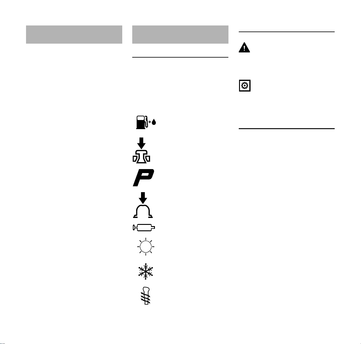
Pictograms
The meanings of the pictograms
attached to the machine are explained in
this manual.
Depending on the model concerned, the
following pictograms may be attached to
your machine.
Fuel tank; fuel mixture of
gasoline and engine oil
Operate decompression
valve
Manual fuel pump
Operate manual fuel
pump
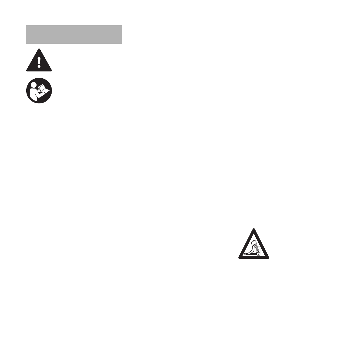
Symbols in text
WARNING
Warning where there is a risk of an
accident or personal injury or serious
damage to property.
NOTICE
Caution where there is a risk of
damaging the machine or its individual
components.
Engineering improvements
STIHL's philosophy is to continually
improve all of its products. For this
reason we may modify the design,
engineering and appearance of our
products periodically.
Therefore, some changes, modifications
and improvements may not be covered
in this manual.
Tube of grease
Intake air: Summer
operation
Intake air: Winter
operation
Handle heating
2
KM 111 R, KM 131, KM 131 R
English
Safety Precautions and
Working Techniques
Special safety precautions must be observed
when working with a
power tool.
Always read and and
make sure you understand both instruction
manuals (KombiEngine
and KombiTool) before
using your power tool for
the first time and keep
them in a safe place for
future reference. Nonobservance of the safety
precautions may result in
serious or even fatal
injury.
Observe all applicable local safety
regulations, standards and ordinances.
If you have not used this type of power
tool before: Have your dealer or other
experienced user show you how it is
operated or attend a special course in its
operation.
Minors should never be allowed to use a
power tool.
Keep bystanders, especially children,
and animals away from the work area.
When the power tool is not in use, shut it
off so that it does not endanger others.
Secure it against unauthorized use.
The user is responsible for avoiding
injury to third parties or damage to their
property.
Lend or rent your power tool only to
persons who are familiar with this model
and its operation – do not lend your
power tool without the KombiEngine and
KombiTool instruction manuals.
The use of noise emitting power tools
may be restricted to certain times by
national or local regulations.
To operate the power tool you must be
rested, in good physical condition and
mental health.
If you have any condition that might be
aggravated by strenuous work, check
with your doctor before operating a
power tool.
Persons with pacemakers only: The
ignition system of your power tool
produces an electromagnetic field of a
very low intensity. This field may
interfere with some pacemakers. STIHL
recommends that persons with
pacemakers consult their physician and
the pacemaker manufacturer to reduce
any health risk.
Do not operate the power tool if you are
under the influence of any substance
(drugs, alcohol) which might impair
vision, dexterity or judgment.
Use your power tool only for the
applications described in the instruction
manual of the KombiTool you are using.
Do not use your po we r tool for any other
purpose because of the increased risk of
accidents.
Do not operate the KombiEngine without
a properly mounted KombiTool since
this may result in damage to the
machine.
Only use KombiTools and accessories
that are explicitly approved for this
power tool by STIHL or are technically
identical. It is important that you read the
chapter on "Approved KombiTools". If
you have any questions in this respect,
consult a servicing dealer. Use only high
quality tools and accessories in order to
avoid the risk of accidents and damage
to the machine.
STIHL recommends the use of genuine
STIHL tools and accessories. They are
specifically designed to match the
product and meet your performance
requirements.
Never attempt to modify your machine in
any way since this may increase the risk
of personal injury. STIHL excludes all
liability for personal injury and damage
to property caused while using
unauthorized attachments.
Do not use a pressure washer to clean
your power tool. The solid jet of water
may damage parts of the power tool.
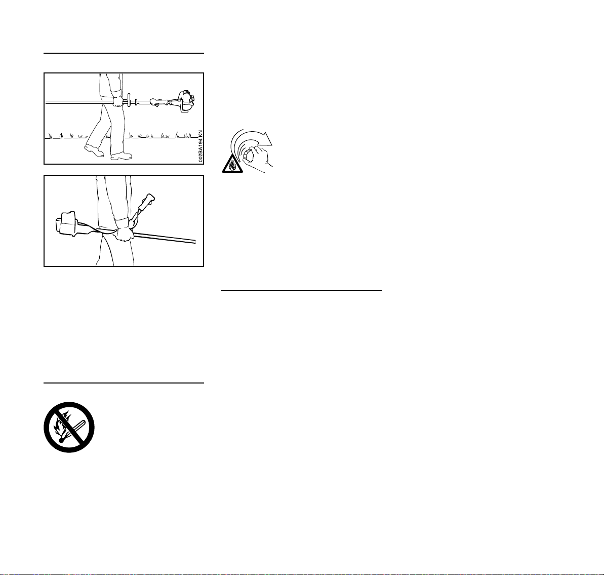
Clothing and Equipment
Wear proper protective clothing and
equipment.
Avoid clothing that could
get caught on branches
or brush or moving parts
of the machine. Do not
wear a scarf, necktie or
jewelry. Tie up and confine long hair (e.g. with a
hair net, cap, hard hat,
etc.).
See also notes on "Clothing and
Equipment" in the instruction manual of
the KombiTool you are using.
KM 111 R, KM 131, KM 131 R
3
English
002BA079 KN
Transporting the Power Tool
Always shut off the engine.
Transporting by vehicle: Properly secure
your power tool to prevent turnover, fuel
spillage and damage.
See also notes on "Transporting the
Machine" in the instruction manual of the
KombiTool you are using.
Fueling
Gasoline is an extremely
flammable fuel. Keep
clear of naked flames. Do
not spill any fuel – do not
smoke.
Always shut off the engine before
refueling.
Do not fuel a hot engine – fuel may spill
and cause a fire.
Open the fuel cap carefully to allow any
pressure build-up in the tank to release
slowly and avoid fuel spillage.
Fuel your power tool only in wellventilated areas. If you spill fuel, wipe
the machine immediately – if fuel gets on
your clothing, change immediately.
After fueling, tighten
down the fuel tank cap as
securely as possible.
This reduces the risk of unit vibrations
causing the fuel cap to loosen or come
off and spill quantities of fuel.
To reduce the risk of serious or fatal
burn injuries, check for fuel leakage. If
fuel leakage is found, do not start or run
the engine until leak is fixed.
Before Starting
Check that your power tool is properly
assembled and in good condition – refer
to appropriate chapters in the instruction
manuals.
– Check the fuel system for leaks,
paying special attention to visible
parts such as the tank cap, hose
connections and the manual fuel
pump (on machines so equipped). If
there are any leaks or damage, do
not start the engine – risk of fire.
Have your machine repaired by a
servicing dealer before using it
again.
– Use only an approved combination
of cutting attachment, deflector,
handle and harness. All parts must
be assembled properly and
securely.
– The stop switch must move freely.
– Check smooth action of choke
knob, throttle trigger lockout and
throttle trigger – the throttle trigger
must return automatically to the idle
position. The choke knob must
spring back from the g and <
positions to the run position F when
the throttle trigger lockout and
throttle trigger are squeezed.
– Check that the spark plug boot is
secure – a loose boot may cause
arcing that could ignite combustible
fumes and cause a fire.
– Never attempt to modify the controls
or safety devices in any way.
– Keep the handles dry and clean –
free from oil and dirt – for safe
control of the power tool.
– Adjust the harness and handle(s) to
suit your height and reach.
To reduce the risk of accidents, do not
operate your power tool if it is damaged
or not properly assembled.
If you use a shoulder strap or full
harness: Practice removing and putting
down the machine as you would in an
emergency. To avoid damage, do not
throw the machine to the ground when
practicing.
4
KM 111 R, KM 131, KM 131 R
English
002BA257 KN
See also notes on "Before Starting" in
the instruction manual of the KombiTool
you are using.
Start the engine.
Start the engine at least 3 meters from
the fueling spot, outdoors only.
Place the power tool on firm ground in
an open area. Make sure you have good
balance and secure footing. Hold the
power tool securely. The attachment
must be clear of the ground and all other
obstructions because it may begin to run
when the engine starts.
To reduce the risk of injury, avoid
contact with the attachment.
Do not drop start the power tool – start
the engine as described in the
instruction manual. Note that the
attachment continues to run for a short
period after you let go of the throttle
trigger – flywheel effect.
Check idle speed setting: The
attachment must be stationary when the
engine is idling with the throttle trigger
released.
To reduce the risk of fire, keep hot
exhaust gases and hot muffler away
from easily combustible materials (e.g.
wood chips, bark, dry grass, fuel).
See also notes on "Starting / Stopping
the Engine" in the instruction manual of
the KombiTool you are using.
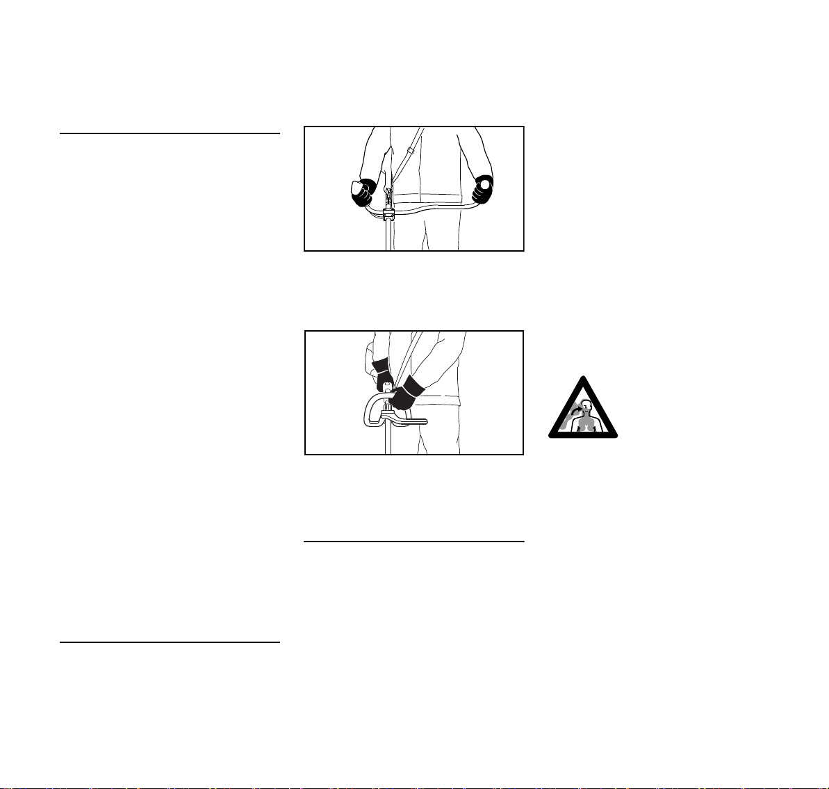
Holding and Controlling the Power Tool
Always hold the power tool firmly with
both hands on the handles.
Make sure you always have good
balance and secure footing.
Models with bike handle
Right handle on control handle, left hand
on left handle.
Models with loop handle
Left hand on loop handle, right hand on
control handle, even if you are lefthanded.
During Operation
In the event of imminent danger or in an
emergency, switch off the engine
immediately – operate the stop switch.
The correct engine idle speed is
important to ensure that the attachment
stops moving when you let go of the
throttle trigger. If the attachment
continues to run when the engine is
idling, have your dealer check your
machine and make proper adjustments
or repairs. Check and correct the idle
speed setting regularly. STIHL
recommends an authorized STIHL
servicing dealer.
Be particularly alert and cautious when
wearing hearing protection because
your ability to hear warnings (shouts,
alarms, etc.) is restricted.
To reduce the risk of accidents, take a
break in good time to avoid tiredness or
exhaustion.
Work calmly and carefully – in daylight
conditions and only when visibility is
good. Stay alert so as not to endanger
others.
Use your power tool only in the areas
specified in the KombiTool instruction
manual.
Your power tool produces
toxic exhaust fumes as
soon as the engine is
running. These fumes
0000-GXX-0492-A0
may be colorless and
odorless and contain
unburned hydrocarbons
and benzol. Never run
the engine indoors or in
poorly ventilated locations, even if your model
is equipped with a catalytic converter.
To reduce the risk of serious or fatal
injury from breathing toxic fumes,
ensure proper ventilation when working
in trenches, hollows or other confined
locations.
To reduce the risk of accidents, stop
work immediately in the event of
nausea, headache, visual disturbances
(e.g. reduced field of vision), problems
KM 111 R, KM 131, KM 131 R
5

English
with hearing, dizziness, deterioration in
ability to concentrate. Apart from other
possibilities, these symptoms may be
caused by an excessively high
concentration of exhaust gases in the
work area.
Operate your power tool so that it
produces a minimum of noise and
emissions – do not run the engine
unnecessarily, accelerate the engine
only when working.
To reduce the risk of fire, do not smoke
while operating or standing near your
power tool. Note that combustible fuel
vapor may escape from the fuel system.
The dusts, vapor and smoke produced
during operation may be dangerous to
health. Wear a suitable respirator in very
dusty or smoky conditions.
If your power tool is subjected to
unusually high loads for which it was not
designed (e.g. heavy impact or a fall),
always check that it is in good condition
before continuing work – see also
"Before Starting". Check the fuel system
in particular for leaks and make sure the
safety devices are working properly. Do
not continue operating your power tool if
it is damaged. In case of doubt, consult
your servicing dealer.
Do not operate your power tool in the
starting throttle position – engine speed
cannot be controlled in this position.
Before leaving the power tool
unattended: Shut off the engine.
To reduce the risk of injury, always shut
off the engine before changing the
KombiTool or attachment.
Vibrations
Prolonged use of the power tool may
result in vibration-induced circulation
problems in the hands (whitefinger
disease).
No general recommendation can be
given for the length of usage because it
depends on several factors.
The period of usage is prolonged by:
– Hand protection (wearing warm
gloves)
– Work breaks
The period of usage is shortened by:
– Any personal tendency to suffer
from poor circulation (symptoms:
frequently cold fingers, tingling
sensations).
– Low outside temperatures.
– The force with which the handles
are held (a tight grip restricts
circulation).
Continual and regular users should
monitor closely the condition of their
hands and fingers. If any of the above
symptoms appear (e.g. tingling
sensation in fingers), seek medical
advice.
Maintenance and Repairs
Service the machine regularly. Do not
attempt any maintenance or repair work
not described in the instruction manual.
Have all other work performed by a
servicing dealer.
STIHL recommends that you have
servicing and repair work carried out
exclusively by an authorized STIHL
servicing dealer. STIHL dealers are
regularly given the opportunity to attend
training courses and are supplied with
the necessary technical information.
Only use high-quality replacement parts
in order to avoid the risk of accidents
and damage to the machine. If you have
any questions in this respect, consult a
servicing dealer.
STIHL recommends the use of original
STIHL replacement parts. They are
specifically designed to match your
model and meet your performance
requirements.
To reduce the risk of injury from
unintentional engine startup, always
shut off the engine and disconnect the
spark plug boot before performing any
repairs, maintenance or cleaning work. –
Exception: Carburetor and idle speed
adjustments.
Do not turn the engine over on the
starter with the spark plug boot or spark
plug removed since there is otherwise a
risk of fire from uncontained sparking.
To reduce the risk of fire, do not service
or store your machine near open flames.
Check the fuel filler cap for leaks at
regular intervals.
Use only a spark plug of the type
approved by STIHL and make sure it is
in good condition – see "Specifications".
Inspect the ignition lead (insulation in
good condition, secure connection).
Check the condition of the muffler.
6
KM 111 R, KM 131, KM 131 R

English
To reduce the risk of fire and damage to
hearing, do not operate your machine if
the muffler is damaged or missing. –
Do not touch a hot muffler since burn
injury will result.
Vibration behavior is influenced by the
condition of the AV elements – check the
AV elements at regular intervals.
Approved KombiTools
The following STIHL KombiTools may
be mounted on the KombiEngine:
KombiTool
FS-KM Brushcutter with
FS-KM
FSB-KM
1)
3) 4) 5)
HL-KM 145°
HL-KM 0°
2)
FH-KM 145° Power scythe
BG-KM
HT-KM
3)
2)
BF-KM Cultivator with pick
FCB-KM
FCS-KM
SP-KM
KB-KM
KW-KM
1)
3)
3)
2) 4)
2)
2)
for KombiEngines with loop handle:
The barrier bar supplied with the
loop handle must be used – see
also "Mounting the Loop Handle"
2)
Not approved for KombiEngines
with bike handle
3)
Limited suitability for KombiEngines
with bike handle
4)
Not approved for KM 131 or
KM 131 R
5)
not approved for KM 111 R
Application
mowing head
Brushcutter with
grass cutting blade
Brushcutter with
mowing head
3)
Long reach hedge
trimmer, adjustable
Long reach hedge
trimmer
Blower
Pole pruners
tines
Edger
Edger
Special harvester
Bristle brush
PowerSweep
KM 111 R, KM 131, KM 131 R
7

English
2
002BA098 KN
1
1
5
4
002BA099 KN
2
3
6
7
A
9
8
4
002BA353 KN
Mounting the Loop Handle
A barrier bar is supplied with the
machine. Attach the barrier bar to the
loop handle.
N Insert square nuts (1) in the barrier
bar (2) – the holes must line up
8
N Insert the clamp (3) in the loop
handle (4) and position them
together on the shaft (5)
N Position clamp (6)
N Position barrier bar (2) – note
position!
N Line up the holes
N Insert bolts (7) in the holes – and
screw them into the barrier bar as
far as possible
N Fit the loop handle (4) at a distance
of (A) approx. 20 cm (8 in) forward
of the control handle (8)
N Orient the loop handle
N Tighten the bolts – lock the nuts if
necessary
The sleeve (9) is present depending on
the country and must be located
between the loop handle and control
handle.
Always leave the barrier bar attached.
KM 111 R, KM 131, KM 131 R

English
1
7
A
250BA046 KN
0000-GXX-0510-A0
8
Mounting the Bike Handle
Mounting Bike Handle with Swiveling
Handle Support
The machine is supplied with the
swiveling handle support already
mounted on the shaft. To mount the
handlebar it is necessary to remove the
clamp moldings.
Removing the clamp moldings
N Pull out the wing screw – the
washer (6) remains on the wing
screw.
N Separate the clamp moldings – the
springs (4 and 5) remain in the
lower clamp.
Securing the handlebar
N Place the handlebar (7) in the lower
clamp (1) so that distance A is no
more than 15 cm (6 in).
N Place the upper clamp in position
and hold both clamp moldings
together.
N Push the wing screw through the
two clamps as far as stop – hold all
parts together and secure them.
N Place the secured assembly on the
handle support (8) with the wing
screw at the side nearest the
engine.
N Push the wing screw into the handle
support as far as stop and then
screw it down – but do not finally
tighten yet.
N Line up the handlebar at a right
angle to the drive tube – check
distance A again.
N Tighten down the wing screw firmly.
N Hold the lower clamp (1) and upper
clamp (2) firmly together.
N Release the wing screw (3) – the
clamps are loose once the wing
screw has been released. They are
pushed apart by the two
springs (4 and 5).
KM 111 R, KM 131, KM 131 R
9

English
13
9
11
12
7
13
0000-GXX-0511-A0
10
14
15
0000-GXX-0512-A0
15
14
15
7
3
0000-GXX-0513-A0
Mounting the control handle
N Take out the screw (9) – the nut (10)
remains in the control handle (11).
N Push the control handle onto the
handlebar (7) until the holes (13)
line up – the throttle trigger (12)
must point towards the gearbox.
N Insert the screw (9) and tighten it
down firmly.
Fitting the Throttle Cable
NOTICE
Do not kink the throttle cable or lay it in
tight radii – make sure the throttle trigger
moves freely.
N Push the throttle cable (14) into the
retainers (15).
Adjusting the Throttle Cable
N Check adjustment of throttle cable –
see chapter on "Adjusting the
Throttle Cable".
Swiveling the handlebar
Transport position
N Loosen the wing screw (3) and
unscrew it until the handlebar (7)
can be rotated.
N Rotate the handlebar 90°
counterclockwise and then swing
the handles down.
N Tighten down the wing screw (3)
firmly.
Working position
N Reverse the sequence described
above to swing the handles up and
turn the handlebar clockwise.
10
KM 111 R, KM 131, KM 131 R

English
002BA655 KN
Adjusting the Throttle Cable
It may be necessary to correct the
adjustment of the throttle cable after
assembling the machine or after a
prolonged period of operation.
Adjust the throttle cable only when the
unit is completely and properly
assembled.
N Set the throttle trigger to the full
throttle position.
N Carefully rotate the screw in the
throttle trigger in the direction of the
arrow until you feel initial resistance.
Then rotate it another half turn in the
same direction.
Fuel
Your engine requires a mixture of
gasoline and engine oil.
WARNING
For health reasons, avoid direct skin
contact with gasoline and avoid inhaling
gasoline vapor.
STIHL MotoMix
STIHL recommends the use of STIHL
MotoMix. This ready-to-use fuel mix
contains no benzol or lead, has a high
octane rating and ensures that you
always use the right mix ratio.
STIHL MotoMix uses STIHL HP Ultra
two-stroke engine oil for an extra long
engine life.
MotoMix is not available in all markets.
Mixing Fuel
Gasoline with an ethanol content of
more than 10% can cause running
problems in engines with a manually
adjustable carburetor and should not be
used in such engines.
Engines equipped with M-Tronic deliver
full power when run on gasoline with an
ethanol content of up to 25% (E25).
Engine Oil
If you mix the fuel yourself, use only
STIHL two-stroke engine oil or another
high-performance engine oil in
accordance with JASO FB, JASO FC,
JASO FD, ISO-L-EGB, ISO-L-EGC or
ISO-L-EGD.
STIHL specifies STIHL HP Ultra twostroke engine oil or an equivalent highperformance engine oil in order to
maintain emission limits over the
machine’s service life.
Mix Ratio
STIHL 50:1 two-stroke engine oil: 50
parts gasoline to 1 part oil
Examples
KM 111 R, KM 131, KM 131 R
NOTICE
Unsuitable fuels or lubricants or mix
ratios other than those specified may
result in serious damage to the engine.
Poor quality gasoline or engine oil may
damage the engine, sealing rings, hoses
and the fuel tank.
Gasoline
Use only high-quality brand-name
gasoline with a minimum octane rating
of 90 – leaded or unleaded.
Gasoline STIHL engine oil 50:1
Liters Liters (ml)
1 0.02 (20)
5 0.10 (100)
10 0.20 (200)
15 0.30 (300)
20 0.40 (400)
25 0.50 (500)
N Use a canister approved for storing
fuel. Pour oil into canister first, then
add gasoline and mix thoroughly.
11

English
0000-GXX-0476-A0
002BA447 KN
002BA448 KN
Storing Fuel
Store fuel only in approved safety-type
fuel canisters in a dry, cool and safe
location protected from light and the sun.
Fuel mix ages – only mix sufficient fuel
for a few weeks work. Do not store fuel
mix for longer than 30 days. Exposure to
light, the sun, low or high temperatures
can quickly make the fuel mix unusable.
STIHL MotoMix may be stored for up to
2 years without any problems.
N Thoroughly shake the mixture in the
canister before fueling your
machine.
WARNING
Pressure may build up in the canister –
open it carefully.
N Clean the fuel tank and canister
from time to time.
Dispose of remaining fuel and cleaning
fluid properly in accordance with local
regulations and environmental
requirements.
Fueling
Preparations
N Before fueling, clean the filler cap
and the area around it to ensure that
no dirt falls into the tank.
N Position the machine so that the
tank cap faces up.
Opening the Tank Cap
Filling Up with Fuel
Take care not to spill fuel while fueling
and do not overfill the tank.
STIHL recommends you use the STIHL
filler nozzle for fuel (special accessory).
N Fill up with fuel.
Closing the Tank Cap
N Place the cap in the opening.
N Turn the cap clockwise as far as
stop and tighten it down as firmly as
possible by hand.
12
N Turn the cap counterclockwise until
it can be removed from the tank
opening.
N Remove the tank cap.
KM 111 R, KM 131, KM 131 R

English
2
1
3
0000-GXX-0477-A0
3
1
2
0000-GXX-0494-A0
0000-GXX-0478-A0
Starting / Stopping the
Engine
Controls
Version with Loop Handle
1 Throttle trigger lockout
2 Throttle trigger
3 Stop switch with Run and Stop
positions. Depress the stop switch
(…) to switch off the ignition – see
"Function of stop switch and ignition
system".
Version with Bike Handle
1 Throttle trigger lockout
2 Throttle trigger
3 Stop switch with Run and Stop
positions. Depress the stop switch
(…) to switch off the ignition – see
"Function of stop switch and ignition
system".
Starting the Engine
N Press the manual fuel pump
bulb (9) at least five times – even if
the bulb is already filled with fuel.
N Press in the choke knob (8) and turn
it to the position that suits the engine
temperature:
KM 111 R, KM 131, KM 131 R
Function of stop switch and ignition
system
The ignition is switched off and the
engine stopped when the stop switch is
pressed. The stop switch returns
automatically to the Run position when it
is released: The ignition is switched on
again after the engine stops – the engine
is then ready to start.
g if the engine is cold
< for warm start – also use this posi-
tion if the engine has been running
but is still cold.
The choke knob must engage in
position.
13

English
0000-GXX-1316-A0
0000-GXX-1319-A0
0000-GXX-1318-A0
0000-GXX-1558-A0
Cranking
N Place the power tool on the ground
so that it rests on the machine
support: Check that the working tool
is not touching the ground or any
other obstacles – see also "Starting
/ Stopping the Engine" in the
KombiTool instruction manual.
N Make sure you have a safe and
secure footing.
N Hold the unit with your left hand and
press it down firmly – your thumb
should be under the fan housing.
NOTICE
Do not stand or kneel on the drive tube.
N Hold the starter grip with your right
hand.
N Pull the starter grip slowly until you
feel it engage and then give it a brisk
strong pull.
NOTICE
Do not pull out the starter rope all the
way – it might otherwise break.
N Do not let the starter grip snap back.
Guide it slowly back into the housing
so that the starter rope can rewind
properly.
N Continue cranking until the engine
runs.
As soon as the engine runs
N Press down the throttle trigger
lockout and open the throttle – the
choke knob moves to the run
position F. After a cold start, warm
up the engine by opening the
throttle several times.
WARNING
There is a risk of injury if the KombiTool
runs when the engine is idling. Adjust
the carburetor so that the KombiTool
does not run when the engine is idling –
see “Adjusting the Carburetor”.
Your machine is now ready for
operation.
Stopping the Engine
N Depress the momentary contact
stop switch – the engine stops –
release the stop switch – it springs
back to the run position.
Other Hints on Starting
Engine stalls in cold start position g or
under acceleration.
N Move the choke knob to < and
continue cranking until the engine
runs.
Engine does not start in warm start
position <
N Move the choke knob to g and
continue cranking until the engine
runs.
If the engine does not start
N Check that all settings are correct.
N Check that there is fuel in the tank
and refuel if necessary.
14
KM 111 R, KM 131, KM 131 R

English
1
1
0000-GXX-0482-A0
2
3
4
N Check that the spark plug boot is
properly connected.
N Repeat the starting procedure.
Engine is flooded
N Move the choke knob to F and
continue cranking until the engine
runs.
Fuel tank run until completely dry
N After refueling, press the manual
fuel pump bulb at least five times –
even if the bulb is already filled with
fuel.
N Set the choke lever to suit the
engine temperature.
N Now start the engine.
Operating Instructions Replacing the Air Filter
During break-in period
A factory-new machine should not be
run at high revs (full throttle off load) for
the first three tank fillings. This avoids
unnecessary high loads during the
break-in period. As all moving parts
have to bed in during the break-in
period, the frictional resistances in the
engine are greater during this period.
The engine develops its maximum
power after about 5 to 15 tank fillings.
During Operation
After a long period of full throttle
operation, allow the engine to run for a
short while at idle speed so that engine
heat can be dissipated by the flow of
cooling air. This protects enginemounted components (ignition,
carburetor) from thermal overload.
After Finishing Work
Storing for a short period: Wait for the
engine to cool down. Empty the fuel tank
and keep the machine in a dry place,
well away from sources of ignition, until
you need it again. For longer out-ofservice periods – see "Storing the
Machine".
Filters have an average life of more than
a year. Do not remove the filter cover or
replace the air filter as long as there is no
noticeable loss of power.
If there is a noticeable loss of engine
power
N Turn the choke knob to g.
N Loosen the screws (1).
N Remove the filter cover (2).
N Clean away loose dirt from around
the filter.
N Remove the filter element (3).
N Replace dirty or damaged filter
element (3).
N Replace any damaged parts.
Installing the Filter Element
N Install the filter element (3) in the
filter housing and fit the cover.
N Insert the screws (1) and tighten
them down firmly.
KM 111 R, KM 131, KM 131 R
15

English
0000-GXX-0495-A0
0000-GXX-0486-A0
4
5
Adjusting the Carburetor
The carburetor has been set at the
factory to provide an optimum fuel-air
mixture under most operating
conditions.
Adjusting Idle Speed
Engine stops while idling
N Warm up the engine for about
3 minutes.
N Turn the idle speed screw (LA)
slowly clockwise until the engine
runs smoothly – the attachment
must not run.
Attachment runs when engine is idling
N Turn the idle speed screw (LA)
slowly counterclockwise until the
cutting attachment stops running
and then turn the screw about
another 1/2 to 3/4 turn in the same
direction.
Spark Arresting Screen in
Muffler
N If the engine is down on power,
check the spark arresting screen in
the muffler.
N Wait for the muffler to cool down.
N Take out the screw (4).
N Lift the spark arresting screen (5)
and pull it out.
N Clean the spark arresting
screen (5). If the screen is damaged
or heavily carbonized, install a new
one.
N Refit the spark arresting screen (5).
N Insert the screw (4) and tighten it
down firmly.
Spark Plug
N If the engine is down on power,
difficult to start or runs poorly at idle
speed, first check the spark plug.
N Fit a new spark plug after about 100
operating hours – or sooner if the
electrodes are badly eroded. Install
only suppressed spark plugs of the
type approved by STIHL – see
"Specifications".
Removing the Spark Plug
1
2
3
0000-GXX 0537-A0
N Remove the cover (1).
N Pull off the spark plug boot (2).
N Unscrew the spark plug (3).
WARNING
If the attachment continues to run when
the engine is idling, have your machine
checked and repaired by your servicing
dealer.
16
KM 111 R, KM 131, KM 131 R

English
000BA039 KN
A
1
000BA045 KN
Checking the Spark Plug
N Clean dirty spark plug.
N Check electrode gap (A) and
readjust if necessary – see
"Specifications".
N Rectify the problems which have
caused fouling of the spark plug.
Possible causes are:
– Too much oil in fuel mix.
– Dirty air filter.
– Unfavorable running conditions.
N Use resistor type spark plugs with a
properly tightened adapter nut.
Installing the Spark Plug
N Screw the spark plug (3) into the
cylinder.
N Tighten down the spark plug (3) with
the combination wrench.
N Press the boot (2) firmly onto the
spark plug.
N Fit the cover (1) and screw it down
firmly.
Storing the Machine
For periods of about 3 months or longer
N Drain and clean the fuel tank in a
well ventilated area.
N Dispose of fuel properly in
accordance with local
environmental requirements.
N Run the engine until the carburetor
is dry – this helps prevent the
carburetor diaphragms sticking
together.
N Thoroughly clean the machine.
N Remove, clean and check the
attachment. Coat metal parts with
corrosion inhibiting oil.
N Store the machine in a dry and
secure location Keep out of the
reach of children and other
unauthorized persons.
WARNING
Arcing may occur if the adapter nut (1) is
loose or missing. Working in an easily
combustible or explosive atmosphere
may cause a fire or an explosion. This
can result result in serious injuries or
damage to property.
KM 111 R, KM 131, KM 131 R
17

English
Maintenance and Care
The following intervals apply to normal operating conditions only. If your daily working time is longer or operating conditions are difficult (very dusty work area, etc.),
shorten the specified intervals accordingly.
before starting work
after finishing work or daily
after each refueling stop
weekly
monthly
every 12 months
if problem
if damaged
as required
Visual inspection (condition, leaks) XX
Complete machine
Control handle Check operation XX
Air filter
Manual fuel pump (if fitted)
Pickup body (filter) in fuel tank
Fuel Tank Clean XX
Carburetor
Spark plug
Cooling air inlet
Cylinder fins Have cleaned by servicing dealer
Valve clearance
Spark arresting screen in muffler
Clean XX
Replace any damaged parts X
Visual inspection XX
1)
Replace
Check X
Have repaired by servicing dealer
Have checked by servicing dealer
Have replaced by servicing dealer
Check idle adjustment – the working/cutting attachment must not run
Adjust idle speed X
Adjust electrode gap X
Replace after every 100 operating hours
Visual inspection X
Clean X
If power is low or cranking effort very
high, have valve clearance checked
and, if necessary, adjusted by servicing
2)
dealer
Check XX
Clean or replace XX
2)
2)
2)
XX
2)
XXX
X
X
X
X
X
18
KM 111 R, KM 131, KM 131 R

The following intervals apply to normal operating conditions only. If your daily working time is longer or operating conditions are difficult (very dusty work area, etc.),
shorten the specified intervals accordingly.
before starting work
after finishing work or daily
after each refueling stop
weekly
monthly
every 12 months
if problem
All accessible screws and nuts (not adjusting screws)
Antivibration elements
Safety labels Replace X
1)
Only if there is a noticeable loss of engine power
2)
STIHL recommends an authorized STIHL servicing dealer.
Retighten X
Check XXX
Have replaced by servicing dealer
2)
English
if damaged
X
as required
KM 111 R, KM 131, KM 131 R
19

English
21
22
10
9
10
8
9
11
13
12
14
0000-GXX-0496-A0
15
20
19
15
8
16
17
18
21
22
3
2
1
4
5
6
#
7
14
Main Parts
1 Tank cap
2 Carburetor adjusting screws
3 Starter grip
4 Manual fuel pump
5 Cover
6 Muffler
7 Machine support
8 Throttle trigger
9 Stop switch
10 Throttle trigger lockout
11 Bike handle (handlebar)
12 Handle support
13 Wing screw
14 Throttle cable retainer
15 Carrying ring
16 Choke lever
17 Air filter cover
18 Fuel tank
19 Loop handle
20 Barrier bar
21 Coupling sleeve
22 Wing screw
# Serial Number
20
KM 111 R, KM 131, KM 131 R

English
Specifications
Engine
KM 111 R
Single cylinder four-stroke engine with
mixture lubrication
Displacement: 31.4 cc
Bore: 40 mm
Stroke: 25 mm
Engine power to
ISO 8893:
Idle speed: 2,800 rpm
Cut-off speed (rated): 9,500 rpm
Valve clearance
Inlet valve: 0.10 mm
Exhaust valve: 0.10 mm
KM 131, KM 131 R
Single cylinder four-stroke engine with
mixture lubrication
Displacement: 36.3 cc
Bore: 43 mm
Stroke: 25 mm
Engine power to
ISO 8893:
Idle speed: 2,800 rpm
Cut-off speed (rated): 9,500 rpm
Valve clearance
Inlet valve: 0.10 mm
Exhaust valve: 0.10 mm
1.05 kW
(1.4 bhp) at
7,000 rpm
1.40 kW
(1.9 bhp) at
8,500 rpm
Ignition System
Electronic magneto ignition
Spark plug (resistor
type): NKG CMR 6H
Electrode gap: 0.5 mm
Fuel System
All position diaphragm carburetor with
integral fuel pump
Fuel tank capacity: 710 cc (0.71 l)
Weight
dry, without KombiTool
KM 111 R 4.4 kg
KM 131: 4.8 kg
KM 131 R: 4.4 kg
Features
R Loop handle
Noise and Vibration Data
with KombiTool
For version see "Approved
KombiTools".
For further details on compliance with
Vibration Directive 2002/44/EC visit
www.stihl.com/vib.
Noise and vibration data measurements
include idling and rated maximum speed
in the following ratios.
FCB-KM, FCS-KM, FH-KM,
FS-KM and HT-KM 1 to 1
HL-KM 1 to 4
BF-KM, BG-KM, KB-KM and
KW-KM 1 to 6
The exact noise and vibration
specifications depend on the KombiTool
being used and are described in the
KombiTool’s instruction manual.
Sound pressure level L
to
p
EN ISO 10517, ISO 11201, ISO 22868
KM 111 R: 92 dB(A) ... 99 dB(A)
KM 131: 94 dB(A) ... 100 dB(A)
KM 131 R: 92 dB(A) ... 101 dB(A)
Sound power level L
to ISO 3744,
w
ISO 10517, ISO 22868
KM 111 R: 108 dB(A)
KM 131: 109 dB(A) ... 110 dB(A)
KM 131 R: 109 dB(A) ... 110 dB(A)
Sound power level L
to ISO 3744,
w
ISO 10517, ISO 22868
KM 111 R: 105 dB(A) ... 110 dB(A)
KM 131: 106 dB(A) ... 108 dB(A)
KM 131 R: 106 dB(A) ... 110 dB(A)
Vibration measurement a
hv,eq
to
ISO 8662, ISO 10517, ISO 11789,
ISO 20643, ISO 22867
Handle, left
2
KM 111 R: 2.6 m/s
... 7.2 m/s
KM 131: 2.3 m/s2 ... 5.0 m/s
KM 131 R: 3.4 m/s2 ... 6.1 m/s
2
2
2
KM 111 R, KM 131, KM 131 R
21

English
000BA073 KN
Handle, right
KM 111 R: 2.7 m/s
2
... 6.4 m/s
KM 131: 2.4 m/s2 ... 4.2 m/s
KM 131 R: 3.3 m/s2 ... 6.5 m/s
2
2
2
The K-factor in accordance with
Directive 2006/42/EC is 2.0 dB(A) for
the sound pressure level and sound
power level; the K-factor in accordance
with Directive 2006/42/EC is 2.0 m/s
2
for the vibration level.
REACH
REACH is an EC regulation and stands
for the Registration, Evaluation,
Authorisation and Restriction of
Chemical substances.
For information on compliance with the
REACH regulation (EC) No. 1907/2006
see www.stihl.com/reach.
Exhaust Emissions
The CO2value measured in the EU type
approval procedure is specified at
www.stihl.com/co2.
The measured CO
value was
2
determined on a representative engine
in accordance with a standardized test
procedure under laboratory conditions
and does not represent either an explicit
or implied guarantee of the performance
of a specific engine.
The applicable exhaust emission
requirements are fulfilled by the
intended usage and maintenance
described in this instruction manual. The
type approval expires if the engine is
modified in any way.
Maintenance and Repairs Disposal
Users of this machine may only carry out
the maintenance and service work
described in this user manual. All other
repairs must be carried out by a
servicing dealer.
STIHL recommends that you have
servicing and repair work carried out
exclusively by an authorized STIHL
servicing dealer. STIHL dealers are
regularly given the opportunity to attend
training courses and are supplied with
the necessary technical information.
When repairing the machine, only use
replacement parts which have been
approved by STIHL for this power tool or
are technically identical. Only use highquality replacement parts in order to
avoid the risk of accidents and damage
to the machine.
STIHL recommends the use of original
STIHL replacement parts.
Original STIHL parts can be identified by
the STIHL part number, the {
logo and the STIHL parts symbol K
(the symbol may appear alone on small
parts).
Observe all country-specific waste
disposal rules and regulations.
STIHL products must not be thrown in
the garbage can. Take the product,
accessories and packaging to an
approved disposal site for environmentfriendly recycling.
Contact your STIHL servicing dealer for
the latest information on waste disposal.
22
KM 111 R, KM 131, KM 131 R

English
EC Declaration of Conformity
ANDREAS STIHL AG & Co. KG
Badstr. 115
D-71336 Waiblingen
Germany
declare in exclusive responsibility that
Category: KombiMotor
Make: STIHL
Model: KM 111 R
KM 131
KM 131 R
Displacement:
KM 111 R 31.4 cc
KM 131, KM 131 R 36.3 cc
Serial identification: 4180
conforms to the relevant provisions of
Directives 2011/65/EU, 2006/42/EC and
2014/30/EU and has been developed
and manufactured in compliance with
the following standards in the versions
valid on the date of production:
EN ISO 12100, EN 55012,
EN 61000-6-1 (in conjunction with the
following KombiTools: BF-KM, BG-KM,
FCB-KM, FCS-KM, FH-KM, FS-KM,
HL-KM, HT-KM, KB-KM and KW-KM)
The KombiEngine described here may
be operated only in conjunction with the
KombiTools approved by STIHL for use
with this KombiEngine.
Technical documents deposited at:
ANDREAS STIHL AG & Co. KG
Produktzulassung (Product Licensing)
The year of manufacture and serial
number are applied to the product.
Done at Waiblingen, 29.11.2018
ANDREAS STIHL AG & Co. KG
Thomas Elsner
Director Product Management and
Services
KM 111 R, KM 131, KM 131 R
23

English
24
KM 111 R, KM 131, KM 131 R


0458-436-8321-A
AUS
G
www.stihl.com
*04584368321A*
0458-436-8321-A
 Loading...