

Page 1
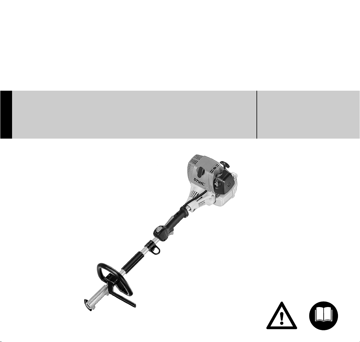
STIHL KM 90 R
Warning!
Read and follow all safety
precautions in Instruction Manual –
improper use can cause serious or
fatal injury.
Advertencia!
Lea y siga todas las precauciones
de seguridad dadas en el manual
de instrucciones – el uso incorrecto
puede causar lesiones graves o
mortales.
{
Instruction Manual
Manual de instrucciones
Page 2

Instruction Manual
1 - 35
Manual de
instrucciones
37 - 74
Page 3

Contents
English
KombiSystem 2
Guide to Using this Manual 2
Safety Precautions and Working
Techniques 3
Approved KombiTools 11
Mounting the Loop Handle 12
Adjusting the Throttle Cable 13
4-MIX Engine 13
Original Instruction ManualPrinted on chlorine-free paper
Fuel 13
Fueling 14
Starting / Stopping the Engine 16
Operating Instructions 18
Cleaning the Air Filter 18
Engine Management 19
Adjusting the Carburetor 19
Spark Arresting Screen in Muffler 20
Spark Plug 21
Replacing the Starter Rope and
Rewind Spring 22
Storing the Machine 25
Maintenance and Care 26
Main Parts 28
Printing inks contain vegetable oils, paper can be recycled.
Specifications 29
Special Accessories 30
Maintenance and Repairs 30
STIHL Incorporated Federal
Emission Control Warranty
Statement 31
STIHL Incorporated California
Exhaust and Evaporative
Emissions Control Warranty
Statement 33
Trademarks 35
Allow only persons who fully understand
the manuals of the KombiEngine and the
KombiTool to operate this power tool
combination.
To receive maximum performance and
satisfaction from your STIHL power tool,
it is important that you read, understand
and follow the safety precautions and
the operating and maintenance
instructions in chapter "Safety
Precautions and Working Techniques"
before using your power tool. For further
information you can go to
www.stihlusa.com.
Contact your STIHL dealer or the STIHL
distributor for your area if you do not
understand any of the instructions in the
two manuals.
Warning!
Because this KombiEngine is the
engine for a high-speed power tool,
some special safety precautions must
be observed to reduce the risk of personal injury. Careless or improper use
may cause serious or even fatal injury.
{
© ANDREAS STIHL AG & Co. KG, 2011
0458-465-8621-B. M11.F11.CP.
0000000811_006_GB
KM 90 R
1
Page 4
English
.
.
.
.
002BA442 KN
+
+
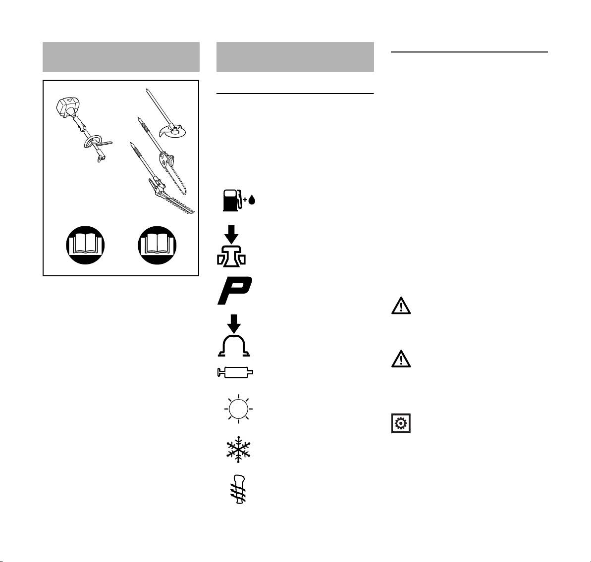
KombiSystem
In the STIHL KombiSystem a number of
different KombiEngines and KombiTools
can be combined to produce a power
tool. In this instruction manual the
functional unit formed by the
KombiEngine and KombiTools is
referred to as the power tool.
Therefore, the separate instruction
manuals for the KombiEngine and
KombiTool should be used together for
the power tool.
Always read and and make sure you
understand both instruction manuals
before using your power tool for the first
time and keep them in a safe place for
future reference.
Guide to Using this Manual
Pictograms
The meanings of the pictograms
attached to or embossed on the
machine are explained in this manual.
Depending on the model concerned, the
following pictograms may be on your
machine.
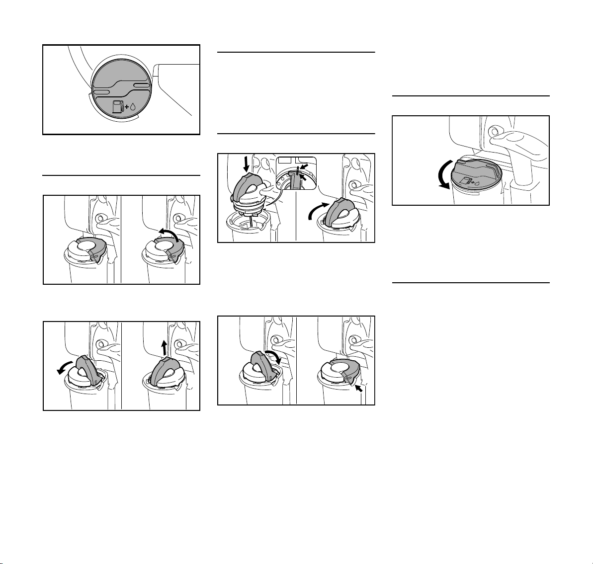
Fuel tank for gasoline
and engine oil mixture
Press to operate decompression valve
Manual fuel pump
Press to operate manual
fuel pump
Filler hole for gear
lubricant
Air intake summer mode
Air intake winter mode
Handle heating
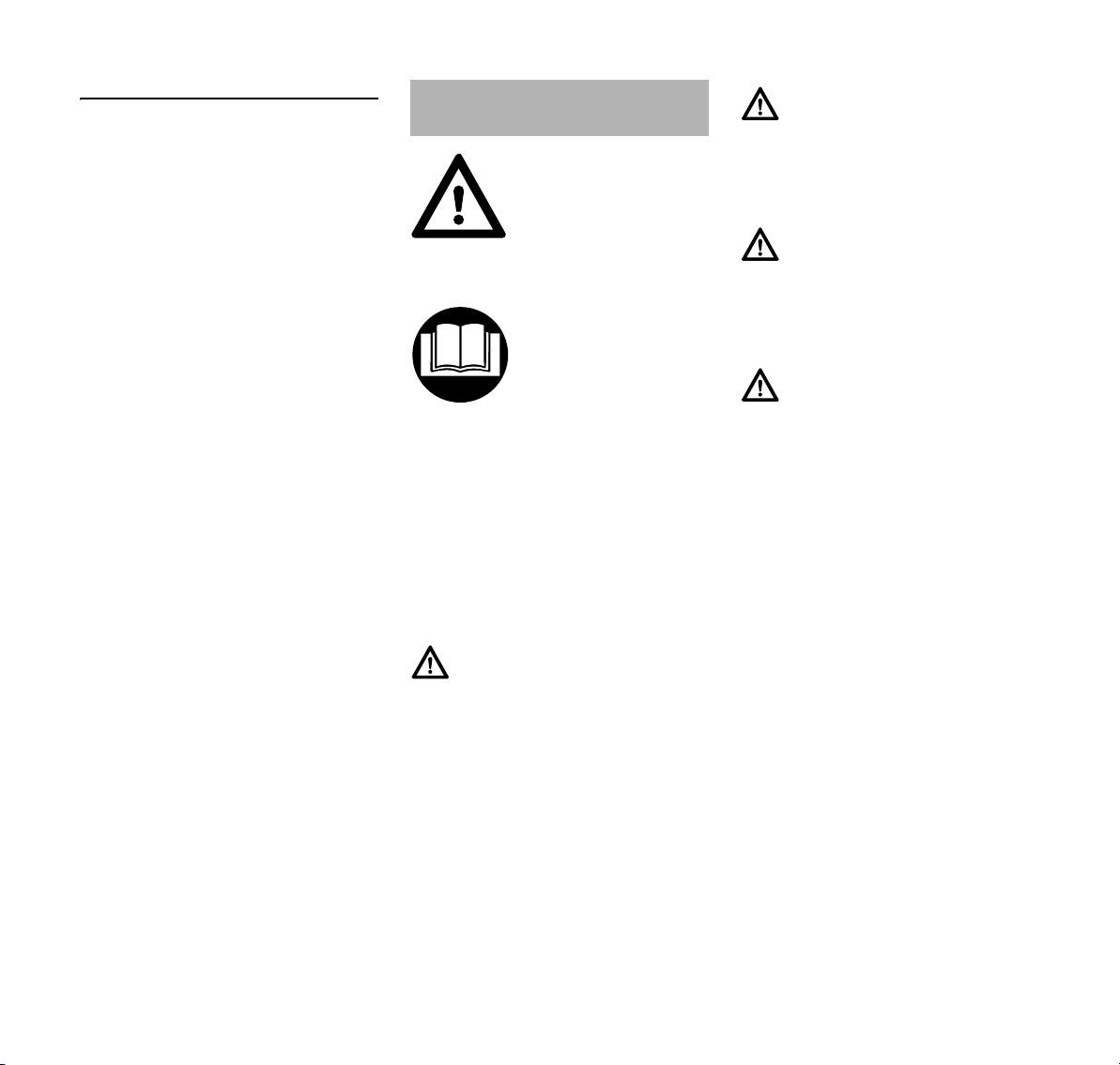
Symbols in Text
Many operating and safety instructions
are supported by illustrations.
The individual steps or procedures
described in the manual may be marked
in different ways:
N A bullet marks a step or procedure.
A description of a step or procedure that
refers directly to an illustration may
contain item numbers that appear in the
illustration. Example:
N Loosen the screw (1).
N Lever (2) ...
In addition to the operating instructions,
this manual may contain paragraphs
that require your special attention. Such
paragraphs are marked with the
symbols and signal words described
below:
Danger!
Indicates an imminent risk of severe or
fatal injury.
Warning!
Indicates a hazardous situation which, if
not avoided, could result in severe or
fatal injury.
Caution!
Indicates a risk of property damage,
including damage to the machine or its
individual components.
2
KM 90 R
Page 5
English
Engineering Improvements
STIHL’s philosophy is to continually
improve all of its products. As a result,
engineering changes and improvements
are made from time to time. Therefore,
some changes, modifications and
improvements may not be covered in
this manual. If the operating
characteristics or the appearance of
your machine differs from those
described in this manual, please contact
your STIHL dealer for assistance.
Safety Precautions and
Working Techniques
Because this KombiEngine is the engine for a
high-speed power tool,
special safety precautions must be observed to
reduce the risk of personal injury.
It is important that you
read, fully understand
and observe the following
safety precautions and
warnings. Read the
instruction manuals and
the safety precautions of
your KombiEngine and
KombiTool periodically.
Careless or improper use
may cause serious or
fatal injury.
Have your STIHL dealer show you how
to operate your power tool. Observe all
applicable local safety regulations,
standards and ordinances.
Warning!
Do not lend or rent your power tool without the instruction manuals. Be sure that
anyone using it understands the information contained in these manuals.
Use your power tool only for the
applications described in the instruction
manual of the KombiTool you are using.
Warning!
Do not use it for other purposes, since
misuse may result in personal injury or
property damage, including damage to
the machine.
Warning!
Minors should never be allowed to use
this power tool. Bystanders, especially
children, and animals should not be
allowed in the area where it is in use.
Warning!
To reduce the risk of injury to bystanders and damage to property, never let
your power tool run unattended. When it
is not in use (e.g. during a work break),
shut it off and make sure that unauthorized persons do not use it.
Most of these safety precautions and
warnings apply to the use of all STIHL
power tools. Different models may have
different parts and controls. See the
appropriate section of your
KombiEngine and KombiTool instruction
manuals for a description of the controls
and the function of the parts of your
model.
Do not clean your machine with a
pressure washer. The solid jet of water
may damage parts of the machine.
Safe use of a KombiEngine involves
1. the operator
2. the power tool
3. the use of the power tool
KM 90 R
3
Page 6
English
THE OPERATOR
Physical Condition
You must be in good physical condition
and mental health and not under the
influence of any substance (drugs,
alcohol, etc.) which might impair vision,
dexterity or judgment. Do not operate
this machine when you are fatigued.
Warning!
Be alert – if you get tired, take a break.
Tiredness may result in loss of control.
Working with any power tool can be
strenuous. If you have any condition
that might be aggravated by strenuous
work, check with your doctor before
operating this machine.
Warning!
Prolonged use of a power tool (or other
machines) exposing the operator to
vibrations may produce whitefinger disease (Raynaud's phenomenon) or
carpal tunnel syndrome.
These conditions reduce the hand's
ability to feel and regulate temperature,
produce numbness and burning
sensations and may cause nerve and
circulation damage and tissue necrosis.
All factors which contribute to
whitefinger disease are not known, but
cold weather, smoking and diseases or
physical conditions that affect blood
vessels and blood transport, as well as
high vibration levels and long periods of
exposure to vibration are mentioned as
factors in the development of whitefinger
disease. In order to reduce the risk of
whitefinger disease and carpal tunnel
syndrome, please note the following:
– Most STIHL power tools are
available with an anti-vibration
("AV") system designed to reduce
the transmission of vibrations
created by the machine to the
operator's hands. An AV system is
recommended for those persons
using power tools on a regular or
sustained basis.
– Wear gloves – not while using
KombiTool BG-KM – and keep your
hands warm.
– Keep the AV system well
maintained. A power tool with loose
components or with damaged or
worn AV elements will tend to have
higher vibration levels.
– Maintain a firm grip at all times, but
do not squeeze the handles with
constant, excessive pressure. Take
frequent breaks.
All the above-mentioned precautions do
not guarantee that you will not sustain
whitefinger disease or carpal tunnel
syndrome. Therefore, continual and
regular users should closely monitor the
condition of their hands and fingers. If
any of the above symptoms appear,
seek medical advice immediately.
Warning!
The ignition system of the STIHL unit
produces an electromagnetic field of a
very low intensity. This field may interfere with some pacemakers. To reduce
the risk of serious or fatal injury, persons
with a pacemaker should consult their
physician and the pacemaker manufacturer before operating this tool.
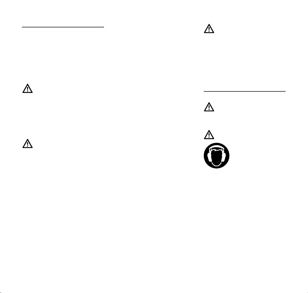
Proper Clothing
Warning!
To reduce the risk of injury, the operator
should wear proper protective apparel.
Warning!
Power tool noise may
damage your hearing.
Wear sound barriers (ear
plugs or ear mufflers) to
protect your hearing.
Continual and regular
users should have their hearing
checked regularly.
Be particularly alert and cautious when
wearing hearing protection because
your ability to hear warnings (shouts,
alarms, etc.) is restricted.
For further instructions on proper
clothing see the safety precautions in
the instruction manual of the KombiTool
you are using.
4
KM 90 R
Page 7
English
THE POWER TOOL
For illustrations and definitions of the
power tool parts see the chapter on
"Main Parts and Controls."
Warning!
Never modify this power tool in any way.
Only attachments supplied by STIHL or
expressly approved by STIHL for use
with the specific STIHL KombiEngine
model are authorized. Although certain
unauthorized attachments are useable
with STIHL power tools, their use may,
in fact, be extremely dangerous.
If this tool is subjected to unusually high
loads for which it was not designed (e.g.
heavy impact or a fall), always check
that it is in good condition before
continuing work. Check in particular that
the fuel system is tight (no leaks) and
that the controls and safety devices are
working properly. Do not continue
operating this machine if it is damaged.
In case of doubt, have it checked by your
STIHL servicing dealer.
THE USE OF THE POWER TOOL
Transporting the Power Tool
Warning!
Always switch off the engine and make
sure the working tool has stopped
before putting a power tool down. When
transporting your power tool in a vehicle, properly secure it to prevent
turnover, fuel spillage and damage to
the power tool.
Fuel
Your STIHL power tool uses an oilgasoline mixture for fuel (see the
chapter on "Fuel" of your instruction
manual).
Warning!
Gasoline is an extremely
flammable fuel. If spilled
and ignited by a spark or
other ignition source, it
can cause fire and seri-
ous burn injury or
property damage. Use extreme caution
when handling gasoline or fuel mix. Do
not smoke or bring any fire or flame near
the fuel or the power tool. Note that
combustible fuel vapor may escape
from the fuel system.
Fueling Instructions
Warning!
To reduce the risk of serious injury from
burns, never attempt to refuel the unit
until it has been completely removed
from the operator.
Warning!
Fuel your power tool in well-ventilated
areas, outdoors. Always shut off the
engine and allow it to cool before refueling. Gasoline vapor pressure may
build up inside the fuel tank depending
on the fuel used, the weather conditions
and the tank venting system.
In order to reduce the risk of burns and
other personal injury from escaping gas
vapor and fumes, remove the fuel filler
cap on your power tool carefully so as to
allow any pressure build-up in the tank
to release slowly. Never remove the fuel
filler cap while the engine is running.
Select bare ground for fueling and move
at least 10 feet (3 m) from the fueling
spot before starting the engine. Wipe off
any spilled fuel before starting your
machine.
Warning!
Check for fuel leakage
while refueling and during operation. If fuel
leakage is found, do not
start or run the engine
until the leak is fixed and
any spilled fuel has been wiped away.
Take care not to get fuel on your clothing. If this happens, change your
clothing immediately.
Different models may be equipped with
different fuel caps.
Toolless cap with grip
Warning!
In order to reduce the risk of fuel spillage and fire from an improperly
tightened fuel cap, correctly position
and tighten the fuel cap in the fuel tank
opening.
KM 90 R
5
Page 8
English
001BA220 KN
001BA227 KN
001BA226 KN
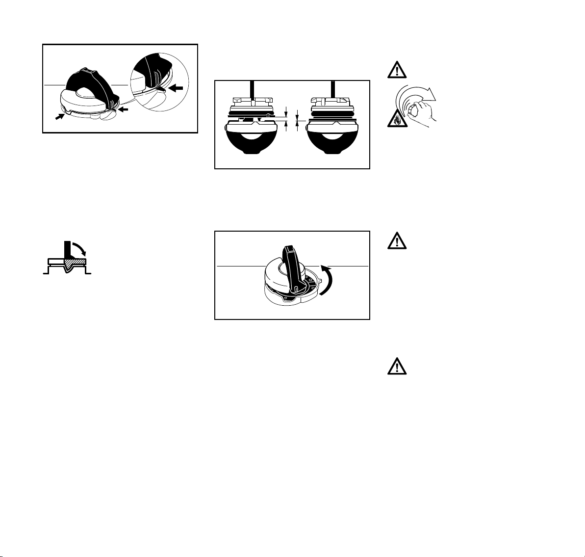
To do this with this STIHL cap, raise the
grip on the top of the cap until it is upright
at a 90° angle. Insert the cap in the fuel
tank opening with the raised positioning
marks on the grip of the cap and on the
fuel tank opening lining up. Using the
grip, press the cap down firmly while
turning it clockwise as far as it will go
(approx. 1/4 turn).
Fold the grip flush with
the top of the cap. Grip
the cap and check for
tightness. If the grip does
not lie completely flush
with the cap and the
detent on the grip does
not fit in the corresponding recess in the filler
opening, or if the cap is
loose in the filler opening,
the cap is not properly
seated and tightened and
you must repeat the
above steps.
Misaligned, damaged or broken cap
N If the cap does not drop fully into the
opening when the positioning marks
line up and/or if the cap does not
tighten properly when twisted, the
base of the cap may be prematurely
rotated (in relation to the top) to the
closed position. Such misalignment
can result from handling, cleaning
or an improper attempt at
tightening.
Left: Base of cap in closed posi-
tion (with open space)
Right: Base of cap correctly posi-
tioned for installation
N To return the cap to the open
position for installation, turn the cap
(with the grip up) until it drops fully
into the tank opening. Next, twist the
cap counterclockwise as far as it will
go (approx. 1/4 turn) – this will twist
the base of the cap into the correct
position. Then, twist the cap
clockwise, closing it normally.
N If your cap still does not tighten
properly, it may be damaged or
broken; immediately stop use of the
unit and take it to your authorized
STIHL dealer for repair.
Screw Cap
Warning!
Unit vibrations can cause
an improperly tightened
fuel filler cap to loosen or
come off and spill quantities of fuel. In order to
reduce the risk of fuel
spillage and fire, tighten the fuel filler
cap by hand as securely as possible.
See also the "Fueling" chapter in your
Instruction Manual for additional
information.
Before Starting
Warning!
Always check your power tool for proper
condition and operation before starting,
particularly the throttle trigger, throttle
trigger lockout, stop switch, cutting
attachment, deflector and harness. The
throttle trigger must move freely and
always spring back to the idle position.
Never attempt to modify the controls or
safety devices.
Warning!
Never operate your power tool if it is
damaged, improperly adjusted or maintained, or not completely or securely
assembled.
6
KM 90 R
Page 9
Warning!
002BA057 KN
Check that the spark plug boot is
securely mounted on the spark plug – a
loose boot may cause arcing that could
ignite combustible fumes and cause a
fire.
Keep the handles clean and dry at all
times; it is particularly important to keep
them free of moisture, pitch, oil, fuel mix,
grease or resin in order for you to
maintain a firm grip and properly control
your power tool.
Starting
Start the engine at least 10 feet (3 m)
from the fueling spot, outdoors only.
For specific starting instructions, see the
appropriate section of your
KombiEngine and KombiTool manuals.
Place the power tool on firm ground or
other solid surface in an open area.
Maintain good balance and secure
footing.
Warning!
To reduce the risk of injury from loss of
control, be absolutely sure that the
working tool is clear of you and all other
obstructions and objects, including the
ground, because when the engine starts
at starting-throttle, engine speed will be
fast enough for the clutch to engage and
move the working tool.
Once the engine has started,
immediately blip the throttle trigger,
which should release the starting throttle
and allow the engine to slow down to
idle.
Warning!
Your power tool is a one-person
machine. Do not allow other persons in
the general work area, even when
starting.
Warning!
To reduce the risk of injury from loss of
control, do not attempt to "drop start"
your power tool.
Warning!
When you pull the starter grip, do not
wrap the starter rope around your hand.
Do not let the grip snap back, but guide
the starter rope to rewind it properly.
Failure to follow this procedure may
result in injury to your hand or fingers
and may damage the starter
mechanism.
See also the safety precautions on
Starting in the instruction manual of the
KombiTool.
Important Adjustments
Warning!
To reduce the risk of personal injury
from loss of control or contact with the
running working tool, do not use a
power tool with incorrect idle adjustment. At correct idle speed, the working
tool should not move. For directions on
how to adjust idle speed, see the appropriate section of your instruction
manual.
English
If you cannot set the correct idle speed,
have your STIHL dealer check your
power tool and make proper
adjustments and repairs.
During Operation
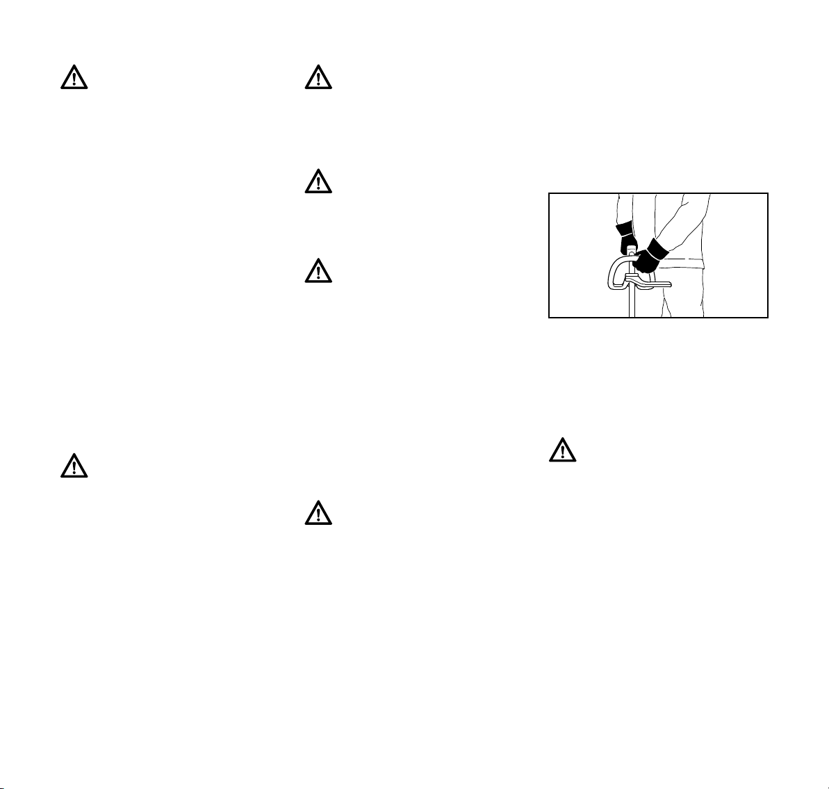
Holding and Controlling the Power
Tool
Always hold the unit firmly with both
hands on the handles while you are
working. Wrap your fingers and thumbs
around the handles.
Your right hand should grip the rear
handle. This also applies to left-handers.
Warning!
To reduce the risk of injury from loss of
control, never work on a ladder or on
any other insecure support.
Working Conditions
Operate and start your power tool only
outdoors in a well ventilated area.
Operate it under good visibility and
daylight conditions only. Work carefully.
KM 90 R
7
Page 10

English
Warning!
As soon as the engine is
running, this product generates toxic exhaust
fumes containing chemicals, such as unburned
hydrocarbons (including
benzene) and carbon monoxide, that
are known to cause respiratory problems, cancer, birth defects, or other
reproductive harm. Some of the gases
(e.g. carbon monoxide) may be colorless and odorless. To reduce the risk of
serious or fatal injury/illness from inhaling toxic fumes, never run the machine
indoors or in poorly ventilated locations.
Warning!
Inhalation of certain dusts, especially
organic dusts such as mold or pollen,
can cause susceptible persons to have
an allergic or asthmatic reaction. Substantial or repeated inhalation of dust
and other airborne contaminants, in particular those with a smaller particle size,
may cause respiratory or other illnesses. Control dust at the source
where possible. Use good work practices, such as operating the unit so that
the wind or operating process directs
any dust raised by the power tool away
from the operator. Follow the recommendations of EPA/OSHA/NIOSH and
occupational and trade associations
with respect to dust ("particulate matter"). When the inhalation of dust cannot
be substantially controlled, i.e., kept at
or near the ambient (background) level,
the operator and any bystanders should
wear a respirator approved by
NIOSH/MSHA for the type of dust
encountered.
Operating Instructions
Warning!
Do not operate your power tool using
the starting throttle lock, as you do not
have control of the engine speed.
In the event of an emergency, switch off
the engine immediately – move the slide
control / stop switch to 0 or STOP.
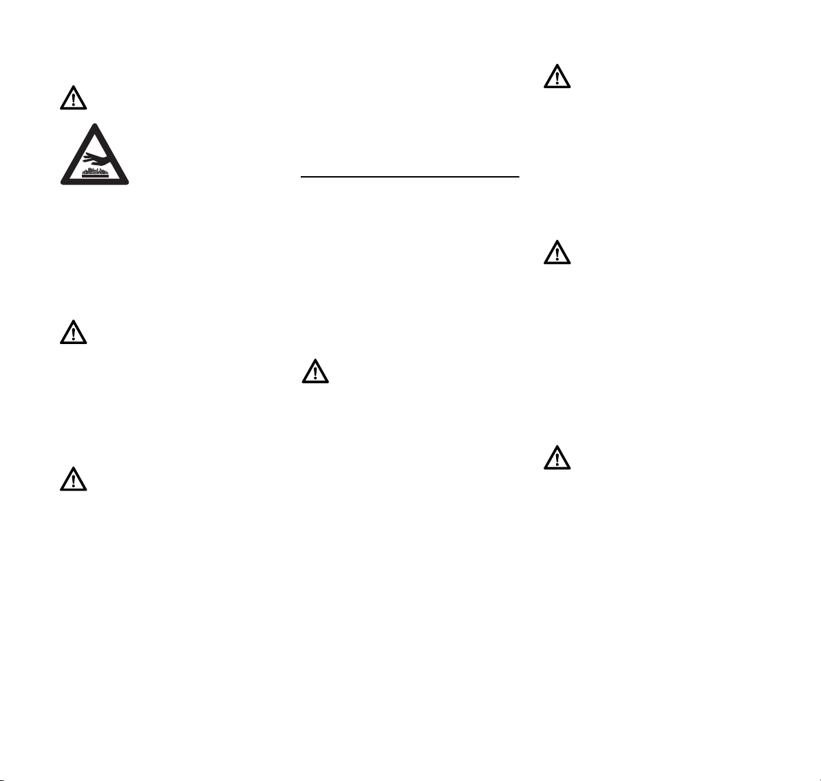
Warning!
The muffler and other parts of the
engine (e.g. fins of the cylinder, spark
plug) become hot during operation and
remain hot for a while after stopping the
engine. To reduce risk of burns do not
touch the muffler and other parts while
they are hot.
Warning!
To reduce the risk of fire and burn injury,
keep the area around the muffler clean.
Remove excess lubricant and all debris
such as pine needles, branches or
leaves. Let the engine cool down sitting
on concrete, metal, bare ground or solid
wood away from any combustible
substances.
Warning!
Never modify your muffler. The muffler
could be damaged and cause an
increase in heat radiation or sparks,
thereby increasing the risk of fire and
burn injury. You may also permanently
damage the engine. Have your muffler
serviced and repaired by your STIHL
servicing dealer only.
8
KM 90 R
Page 11
English
Catalytic Converter
Warning!
Some STIHL power tools
are equipped with a cata-
lytic converter, which is
designed to reduce the
exhaust emissions of the
engine by a chemical
process in the muffler. Due to this process, the muffler does not cool down as
rapidly as conventional mufflers when
the engine returns to idle or is shut off.
To reduce the risk of fire and burn injuries, the following specific safety
precautions must be observed.
Warning!
Since a muffler with a catalytic converter
cools down less rapidly than conventional mufflers, always set your power
tool down in the upright position and
never locate it where the muffler is near
dry brush, grass, wood chips or other
combustible materials while it is still hot.
Warning!
An improperly mounted or damaged cylinder housing or a damaged/deformed
muffler shell may interfere with the cooling process of the catalytic converter.
To reduce the risk of fire or burn injury,
do not continue work with a damaged or
improperly mounted cylinder housing or
a damaged/deformed muffler shell.
Your catalytic converter is furnished with
screens designed to reduce the risk of
fire from the emission of hot particles.
Due to the heat from the catalytic
reaction, these screens will normally
stay clean and need no service or
maintenance. If you experience loss of
performance and you suspect a clogged
screen, have your muffler maintained by
a STIHL servicing dealer.
MAINTENANCE, REPAIR AND
STORING
Maintenance, replacement, or repair
of the emission control devices and
systems may be performed by any
nonroad engine repair establishment
or individual. However, if you make a
warranty claim for a component
which has not been serviced or
maintained properly or if
nonapproved replacement parts were
used, STIHL may deny coverage.
Warning!
Use only identical STIHL replacement
parts for maintenance and repair. Use of
non-STIHL parts may cause serious or
fatal injury.
Strictly follow the maintenance and
repair instructions in the appropriate
section of your KombiEngine and
KombiTool instruction manuals. Please
refer to the maintenance charts
respectively the maintenance notes in
these manuals.
Warning!
Always stop the engine and make sure
that the working tool is stopped before
doing any maintenance or repair work or
cleaning the power tool. Do not attempt
any maintenance or repair work not
described in your KombiEngine and
KombiTool instruction manuals. Have
such work performed by your STIHL
servicing dealer only.
Warning!
Use the specified spark plug and make
sure it and the ignition lead are always
clean and in good condition. Always
press spark plug boot snugly onto spark
plug terminal of the proper size. (Note: If
terminal has detachable SAE adapter
nut, it must be attached.) A loose connection between spark plug boot and
the ignition wire connector in the boot
may create arcing that could ignite combustible fumes and cause a fire.
Warning!
Never test the ignition system with the
ignition wire boot removed from the
spark plug or with a removed spark
plug, since uncontained sparking may
cause a fire.
KM 90 R
9
Page 12

English
Warning!
Do not operate your power tool if the
muffler is damaged, missing or modified. An improperly maintained muffler
will increase the risk of fire and hearing
loss. If your muffler was equipped with a
spark-arresting screen to reduce the
risk of fire, never operate your power
tool if the screen is missing or damaged.
Remember that the risk of forest fires is
greater in hot or dry weather.
Store the power tool in a dry and high or
locked location out of reach of children.
Before storing for longer than a few
days, always empty the fuel tank. See
chapter "Storing the machine" in this
manual.
10
KM 90 R
Page 13
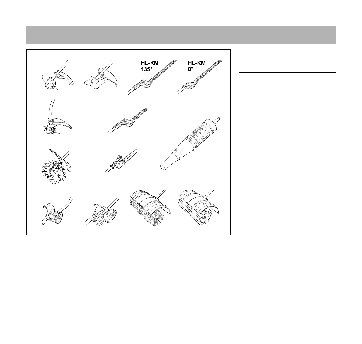
Approved KombiTools
HT-KM
BF-KM
470BA018 KN
FCS-KM
FCB-KM
KW-KM
KB-KM
FH-KM
FS-KM
FS-KM
FSB-KM
BG-KM
English
The following STIHL KombiTools may
be mounted on the KombiEngine:
KombiTool Purpose
FS-KM Brushcutter with
mowing head
FS-KM Brushcutter with
grass cutting blade
FSB-KM Brushcutter with
mowing head
HL-KM 135° Hedge trimmer,
adjustable
HL-KM 0° Hedge trimmer
FH-KM 135° Power scythe
BG-KM Blower
HT-KM Pole pruner
BF-KM Pick tines
FCB-KM Power edger
FCS-KM Power edger
KB-KM Bristle brush
KW-KM PowerSweep
The barrier bar supplied with the
machine must be mounted to the loop
handle – see also "Mounting the Loop
Handle".
KM 90 R
11
Page 14
English
2
002BA098 KN
1
1
5
4
002BA099 KN
2
3
6
7
A
9
8
4
002BA353 KN
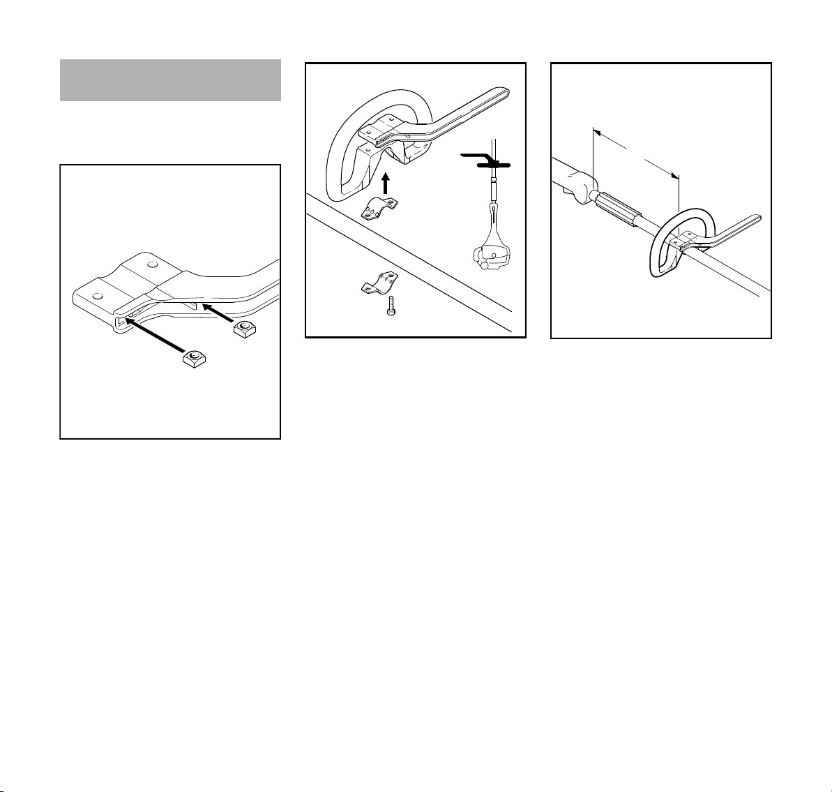
Mounting the Loop Handle
A barrier bar is supplied with the
machine. Attach the barrier bar to the
loop handle.
N Insert square nuts (1) in the barrier
bar (2) – the holes must line up
12
N Insert the clamp (3) in the loop
handle (4) and position them
together on the shaft (5)
N Position clamp (6)
N Position barrier bar (2) – note
position!
N Line up the holes
N Insert bolts (7) in the holes – and
screw them into the barrier bar as
far as possible
N Fit the loop handle (4) at a distance
of (A) approx. 20 cm (8 in) forward
of the control handle (8)
N Orient the loop handle
N Tighten the bolts – lock the nuts if
necessary
The sleeve (9) is present depending on
the country and must be located
between the loop handle and control
handle.
Always leave the barrier bar attached.
KM 90 R
Page 15
English
002BA163 KN
2
1
002BA161 KN
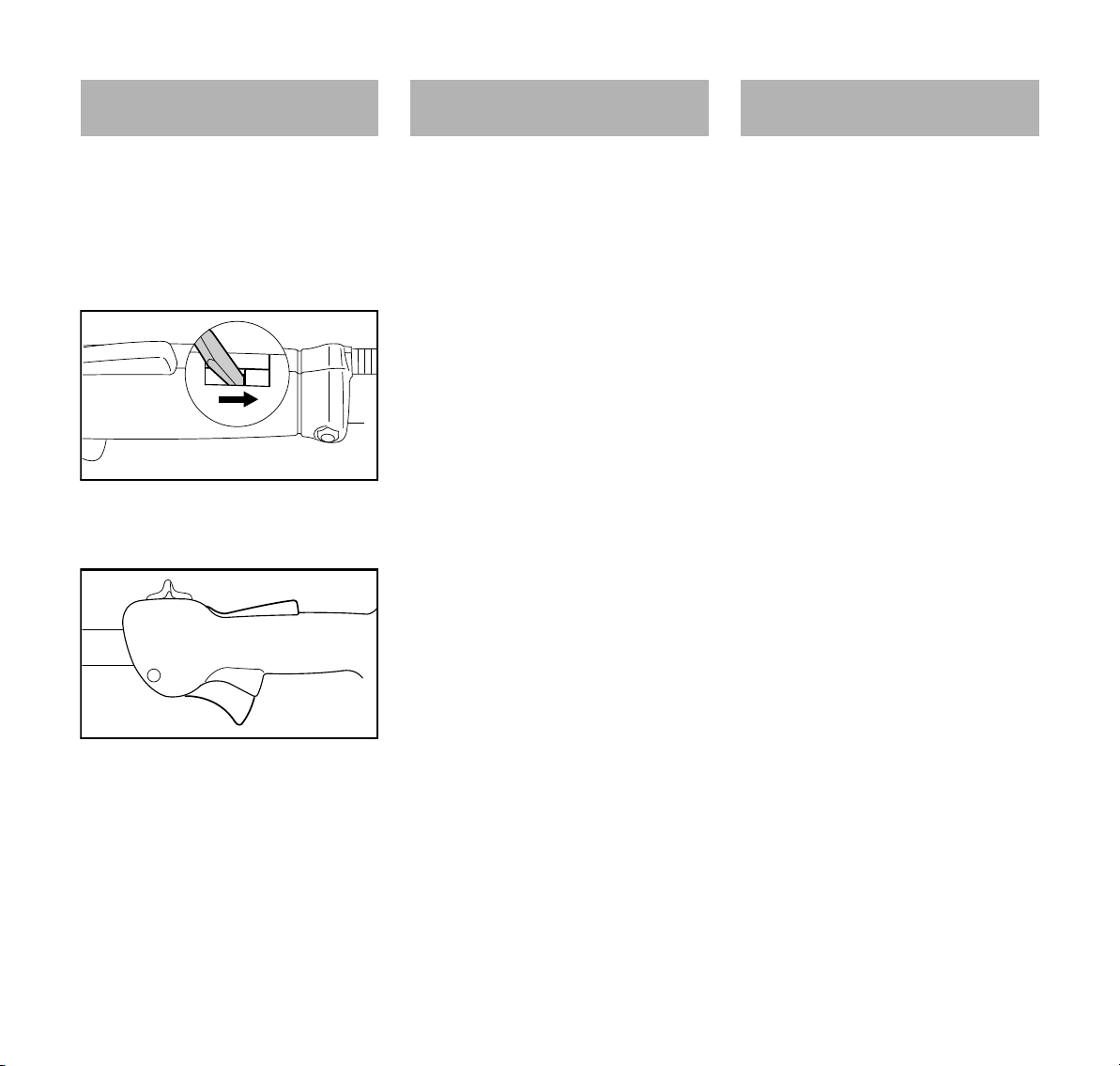
Adjusting the Throttle
Cable
A properly adjusted throttle cable is the
precondition for correct operation in the
full throttle, starting throttle and idle
positions.
N Adjust the throttle cable only when
the unit is completely and properly
assembled.
N Use a suitable tool to push the slide
to the end of the slot (see
illustration).
N Press down the throttle trigger
lockout (1) and squeeze the throttle
trigger (2) (full throttle) – this sets
the throttle cable correctly.
4-MIX Engine Fuel
The STIHL 4-MIX engine features
mixture lubrication and must be run on a
fuel mixture of gasoline and engine oil.
It operates otherwise on the 4-stroke
principle.
This engine is certified to operate on
unleaded gasoline and the STIHL twostroke engine oil at a mix ratio of 50:1.
Your engine requires a mixture of highquality gasoline and two-stroke air
cooled engine oil.
Use mid-grade unleaded gasoline with a
minimum octane rating of 89 (R+M/2)
and no more than 10% ethanol content.
Fuel with a lower octane rating may
increase engine temperatures. This, in
turn, increases the risk of piston seizure
and damage to the engine.
The chemical composition of the fuel is
also important. Some fuel additives not
only detrimentally affect elastomers
(carburetor diaphragms, oil seals, fuel
lines, etc.), but magnesium castings and
catalytic converters as well. This could
cause running problems or even
damage the engine. For this reason
STIHL recommends that you use only
high-quality unleaded gasoline!
Gasoline with an ethanol content of
more than 10% can cause running
problems and major damage in engines
with a manually adjustable carburetor
and should not be used in such engines.
The ethanol content in gasoline affects
engine running speed – it may be
necessary to readjust the carburetor if
you use fuels with various ethanol
contents.
KM 90 R
13
Page 16
English
002BA420 KN
002BA418 KN
Warning!
To reduce the risk of personal injury
from loss of control and / or contact with
the running cutting tool, do not use your
unit with incorrect idle adjustment. At
correct idle speed, the cutting tool
should not move.
If your power tool shows an incorrect
idle adjustment, have your STIHL dealer
check your power tool and make proper
adjustments and repairs.
The idle speed and maximum speed of
the engine change if you switch from a
fuel with a certain ethanol content to
another fuel with a much higher or lower
ethanol content.
This problem can be avoided by always
using fuel with the same ethanol
content.
Use only STIHL two-stroke engine oil or
equivalent high-quality two-stroke
engine oils that are designed for use
only in air cooled two-cycle engines.
We recommend STIHL HP Ultra 2-Cycle
Engine Oil since it is specially
formulated for use in STIHL engines.
Do not use BIA or TCW rated (twostroke water cooled) mix oils or other
mix oils that state they are for use in both
water cooled and air cooled engines
(e.g., outboard motors, snowmobiles,
chain saws, mopeds, etc.).
Take care when handling gasoline.
Avoid direct contact with the skin and
avoid inhaling fuel vapor. When filling at
the pump, first remove the container
from your vehicle and place the
container on the ground before filling. To
reduce the risk of sparks from static
discharge and resulting fire and/or
explosion, do not fill fuel containers that
are sitting in or on a vehicle or trailer.
The container should be kept tightly
closed in order to limit the amount of
moisture that gets into the mixture.
The machine‘s fuel tank should be
cleaned as necessary.
Fuel mix ages
Only mix sufficient fuel for a few days
work, not to exceed 3 months of storage.
Store in approved fuel-containers only.
When mixing, pour oil into the container
first, and then add gasoline. Close the
container and shake it vigorously by
hand to ensure proper mixing of the oil
with the fuel.
Gasoline
Oil (STIHL 50:1 or equivalent high-quality oils)
US gal. US fl.oz.
12.6
2 1/2 6.4
5 12.8
Dispose of empty mixing-oil containers
only at authorized disposal locations.
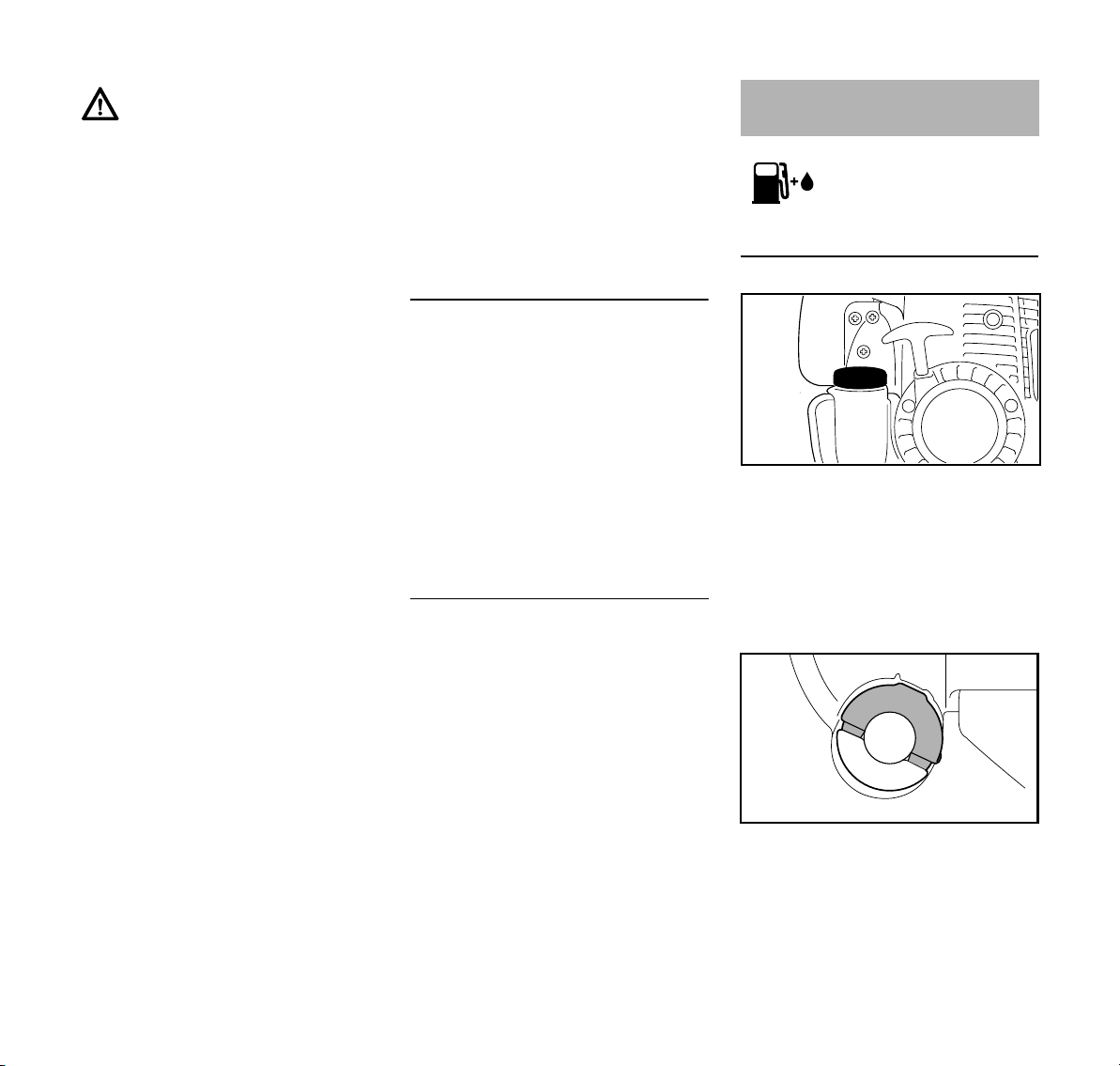
Fueling
Preparations
N Before fueling, clean the filler cap
and the area around it so that dirt
cannot fall into the tank.
N Always position the machine so that
the filler cap is facing upwards.
One of two different filler caps is
installed as standard at the factory.
Toolless filler cap (with folding grip)
14
KM 90 R
Page 17
English
002BA419 KN
249BA053 KN
249BA054 KN
249BA055 KN
249BA056 KN
200BA421 KN
Threaded filler cap
Opening the toolless filler cap
N Swing the grip into an upright
position.
Refueling
Take care not to spill fuel while fueling,
and do not overfill the tank. STIHL
recommends use of the STIHL filling
system (special accessory).
Closing the toolless filler cap
N Position the cap with the grip in an
upright position; the raised
positioning marks must line up.
N Turn cap clockwise as far as it will
go (approx. 1/4 turn).
described above must be repeated. See
also the "Toolless cap with grip" section
in the Safety Precautions.
Opening the threaded filler cap
N Turn the cap counterclockwise until
it can be removed from the tank
opening.
N Remove the filler cap.
Refueling
Take care not to spill fuel while fueling
and do not overfill the tank. STIHL
recommends use of the STIHL filling
system (special accessory).
N Turn the cap counterclockwise
(approx. 1/4 turn).
N Remove the filler cap.
KM 90 R
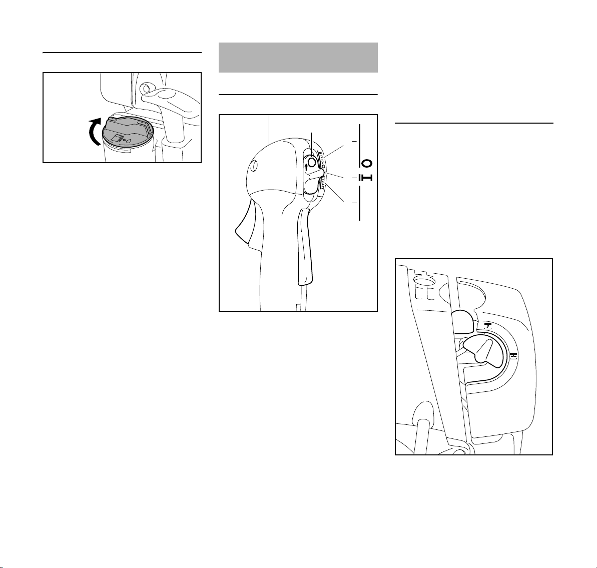
N Fold the grip down so that it is flush
with the surface.
If the grip is not flush with the surface
and the lug on the clip does not engage
entirely in the recess (arrow), the cap is
not properly closed and the steps
15
Page 18
English
200BA422 KN
3
STOP
2
5
6
4
7
002BA181 KN
START
STOP-
1
249BA057 KN
9
8
Closing the threaded filler cap
N Position cap.
N Turn the cap clockwise as far as it
will go and tighten it as securely as
possible by hand.
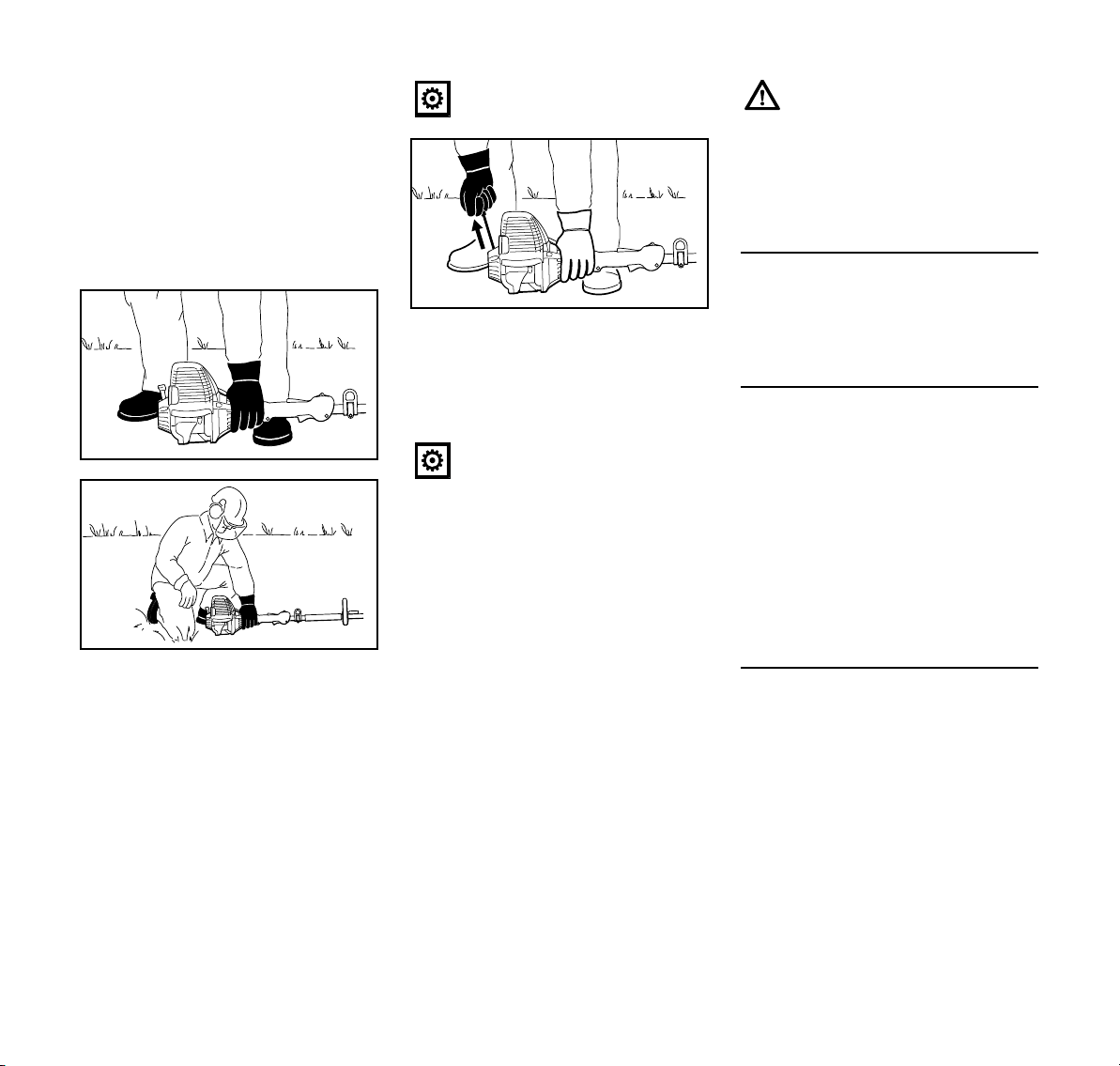
Starting / Stopping the
Engine
Controls
1 Throttle trigger lockout
2 Throttle lever
3 Slide control
Symbol on slide control
7 h – stop symbol and arrow. To stop
the engine, push the slide control in
the direction of the arrow on the stop
symbol (h) to STOP-0.
Starting
N Press down the trigger lockout lever
and squeeze the throttle trigger.
N and hold them in that position.
N Move the slide control to START
and hold it there.
N Now release the throttle trigger,
slide control and trigger lockout in
that order. This is the starting
throttle position.
Positions of slide control
4STOP-0 – engine off – the ignition is
switched off
5 F – normal run position – the engine
is running or can start
6 START – the ignition is switched on
– the engine can start
N Set the choke knob (8)
16
KM 90 R
Page 19
English
552BA014 KN
552BA015 KN
552BA016 KN
g if the engine is cold
e for warm start – also use this posi-
tion if the engine has been running
but is still cold.
N Press the fuel pump bulb (9) at least
five times – even if the bulb is
already filled with fuel.
Starting
N Place the power tool on the ground
so that it rests on the machine
support: Check that the working tool
is not touching the ground or any
other obstacles – see also
"Starting / Stopping the Engine" in
the KombiTool instruction manual.
N Make sure you have a safe and
secure footing.
N Hold the unit with your left hand and
press it down firmly – your thumb
should be under the fan housing.
Do not stand or kneel on the drive
tube.
N Hold the starter grip with your right
hand.
N Pull the starter grip slowly until you
feel it engage and then give it a brisk
strong pull.
Do not pull out the starter rope all
the way – it might otherwise
break.
N Do not let the starter grip snap back.
Guide it slowly back into the housing
so that the starter rope can rewind
properly.
N Continue cranking.
N After no more than five pulls, move
the choke knob to e.
When the engine begins to fire:
N Continue cranking.
As soon as the engine runs
N Blip the throttle trigger
immediately. The slide control
moves to the normal run position F
– and the engine settles down to idle
speed.
Make sure the carburetor is
correctly adjusted. The working
tool must not move when the
engine is idling.
Your machine is now ready for
operation.
Stopping the engine
N Push the slide control in the
direction of the arrow on the stop
symbol (h) to STOP-0.
At very low outside temperatures:
As soon as the engine runs:
N Blip the throttle trigger to disengage
the starting throttle position. The
slide control moves to the normal
run position (F) – and the engine
settles down to idle speed.
N Open the throttle slightly.
N Warm up the engine for a short
period.
If the engine does not start
Choke knob
If you did not turn the choke knob to e
quickly enough after the engine began to
fire, the combustion chamber is flooded.
N Turn the choke knob to e
N Set the slide control, lockout lever
and throttle trigger to the starting
throttle position.
N Start the engine by pulling the
starter rope briskly – 10 to 20 pulls
may be necessary.
KM 90 R
17
Page 20
English
1
273BA006 KN
2
4
If the engine still does not start
N Move the slide control to STOP-0.
N Remove the spark plug – see
"Spark Plug".
N Dry the spark plug.
N Crank the engine several times with
the starter to clear the combustion
chamber.
N Refit the spark plug – see "Spark
Plug".
N Move the slide control to START.
N Set the choke knob to e – even if
the engine is cold.
N Now start the engine.
Throttle cable adjustment
N Check adjustment of throttle cable –
see chapter on "Adjusting the
Throttle Cable".
Fuel tank run until completely dry
N After refueling, press the fuel pump
bulb at least five times – even if the
bulb is filled with fuel.
N Set the choke knob according to
engine temperature.
N Start the engine.
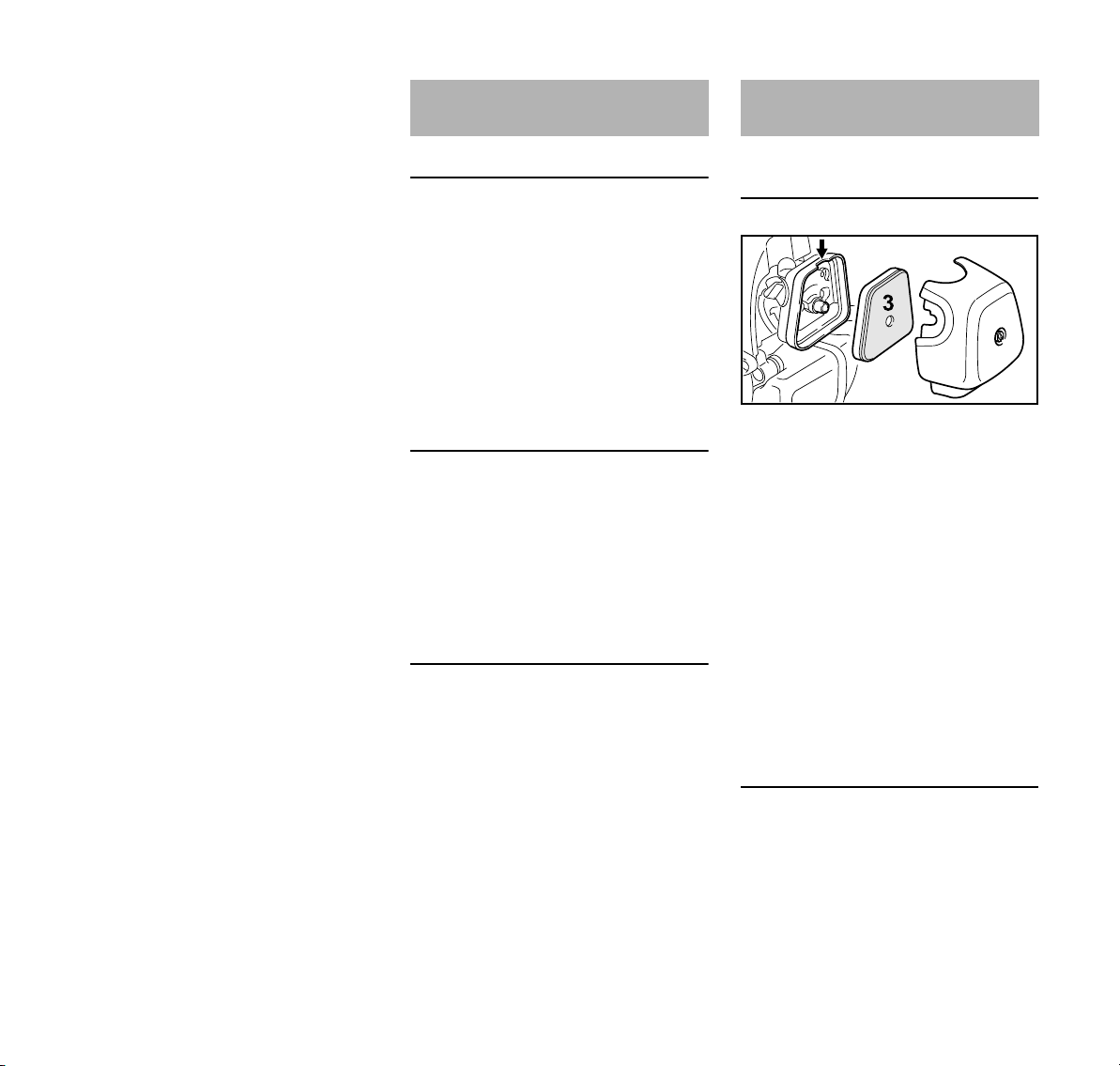
Operating Instructions Cleaning the Air Filter
During break-in period
A factory-new machine should not be
run at high revs (full throttle off load) for
the first three tank fillings. This avoids
unnecessary high loads during the
break-in period. As all moving parts
have to bed in during the break-in
period, the frictional resistances in the
engine are greater during this period.
The engine develops its maximum
power after about 5 to 15 tank fillings.
During Operation
After a long period of full throttle
operation, allow the engine to run for a
short while at idle speed so that engine
heat can be dissipated by the flow of
cooling air. This protects enginemounted components (ignition,
carburetor) from thermal overload.
After Finishing Work
Storing for a short period: Wait for the
engine to cool down. Empty the fuel tank
and keep the machine in a dry place,
well away from sources of ignition, until
you need it again. For longer out-ofservice periods – see "Storing the
Machine".
If there is a noticeable loss of engine
power
N Turn the choke knob to g
N Take out the screw (1) and remove
the filter cover (2).
N Clean away loose dirt from around
the filter.
N Grip the filter element (3) at the
cutout (arrow) in the filter
housing (4) and remove it.
N Fit a new filter element. As a
temporary measure you can knock it
out on the palm of your hand or blow
it out with compressed air. Do not
wash.
N Replace damaged parts.
Installing the filter
N Install the filter element in the filter
housing and fit the cover.
N Insert the screw and tighten it down
firmly.
18
KM 90 R
Page 21
Engine Management Adjusting the Carburetor
249BA051 KN
English
Exhaust emissions are controlled by the
design of the fundamental engine
parameters and components (e.g.
carburation, ignition, timing and valve or
port timing) without the addition of any
major hardware.
The carburetor comes from the factory
with a standard setting.
The carburetor has been adjusted for
optimum performance and fuel
efficiency in all operating states.
The high speed adjusting screw and low
speed adjusting screw on this carburetor
can only be set within narrow limits.
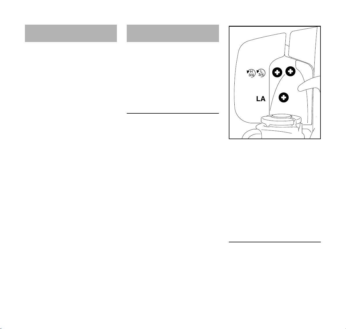
Standard position
N Switch off engine
N Mount KombiTool with attached
working or cutting tool
N Check air filter - clean or replace it if
necessary
N Check throttle cable adjustment,
adjust if necessary – see "Adjusting
the throttle cable"
N Check spark arresting screen -
clean or replace it if necessary
N Carefully turn both adjusting screws
counterclockwise until they are
seated firmly:
– High speed screw (H) is 3/4 of a
turn open
– Low speed screw (L) is 3/4 of a turn
open.
N Start the machine and let the engine
warm up
N Using the idle speed screw (LA), set
the idle speed so that the working
tool does not move
KM 90 R
Fine adjustment
A marginal adjustment of the setting of
the high speed screw (H) may be
necessary if the engine does not run
satisfactorily in mountain country, at sea
level or after changing working tools.
19
Page 22
English
249BA059 KN
1
2
3
2
249BA060 KN
Approx. value
Turn the high speed screw (H) approx.
1/4 turn per 1000 m (3300 ft) difference
in elevation
N Carry out standard adjustment for
idle speed screw (L)
N Let the engine warm up for
approx. 3 min
N Open the throttle fully
In the mountains
N Turn the high speed screw (H)
clockwise (leaner) – until there is no
longer a noticeable increase in
speed – max. as far as possible
At sea level
N Turn the high speed screw (H)
counterclockwise (richer) – until
there is no longer a noticeable
increase in speed – max. as far as
possible
It is possible that the maximum speed is
already obtained at the standard setting.
Setting the idle speed
Cutting attachment turns when idling
N Turn the idle speed screw (LA)
counterclockwise until the working
tool stops moving – then turn
another 1/2 to 3/4 turn in the same
direction
If the working tool continues to
keep moving in idle even after
adjustment, have the machine
checked by a servicing dealer.
Erratic idling behavior, engine stalls
despite correction of LA-setting, poor
acceleration
The idle setting is too lean:
N Turn the low speed screw (L)
counterclockwise until the engine
runs and accelerates smoothly – but
no further than the stop
Erratic idling behavior
The idle setting is too rich:
N Turn the low speed screw (L)
clockwise until the engine runs and
accelerates smoothly – but no
further than the stop
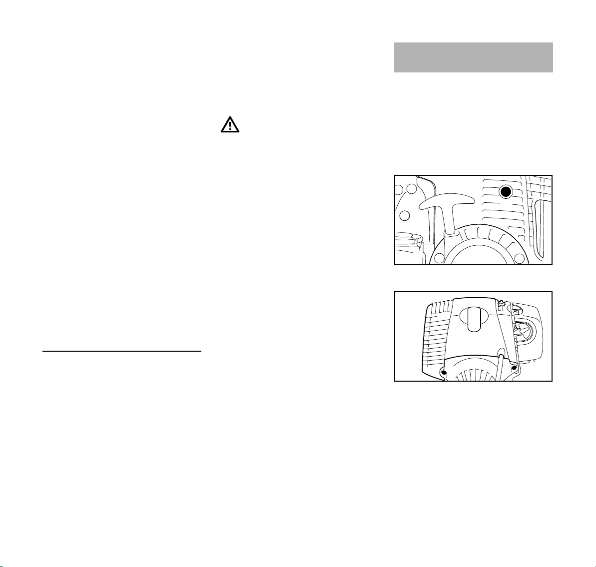
Spark Arresting Screen in
Muffler
In some countries the muffler is
equipped with a spark arresting screen.
N If the engine is down on power,
check the spark arresting screen in
the muffler.
N Wait for the muffler to cool down.
N Move the slide control to STOP-0.
N Take out the screw (1).
Whenever the low speed screw (L) has
been adjusted, it is usually also
necessary to adjust the idle speed
screw (LA).
N Let the engine warm up for
approx. 3 min
Engine stops when idling
N Slowly turn idle speed screw (LA)
clockwise until the engine runs
smoothly – the working tool must
not move
20
N Take out the screws (2) and remove
the shroud (3).
KM 90 R
Page 23
English
1
249BA063 KN
000BA039 KN
A
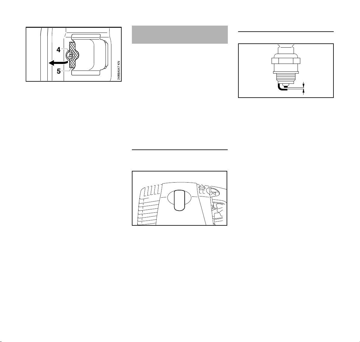
N Take out the screw (4).
N Lift the spark arresting screen (5)
and pull it out.
N Clean the spark arresting screen. If
the screen is damaged or heavily
carbonized, fit a new one.
N Refit the spark arresting screen.
N Insert the screw and tighten it down
firmly.
N Fit the shroud.
Spark Plug
If engine is down on power, difficult to
start or runs poorly at idling speed, first
check the spark plug.
Fit a new spark plug after approx. 100
operating hours or earlier if the
electrodes are badly eroded.
Wrong fuel mix (too much engine oil in
the gasoline), a dirty air filter and
unfavorable running conditions (mostly
at part throttle etc.) affect the condition
of the spark plug. These factors cause
deposits to form on the insulator nose
which may result in trouble in operation.
Removing the spark plug
N Move the slide control to STOP-0.
Checking the Spark Plug
N Clean dirty spark plug.
N Check electrode gap (A) and
readjust if necessary – see
"Specifications".
N Use only resistor type spark plugs of
the approved range.
Rectify problems which have caused
fouling of spark plug:
– Too much oil in fuel mix.
– Dirty air filter.
– Unfavorable running conditions,
e.g. operating at part load.
KM 90 R
N Pull off the spark plug boot (1).
N Unscrew the spark plug.
21
Page 24
English
2
1
002BA363 KN
3
002BA178 KN
2
1
1
249BA061 KN
2
1
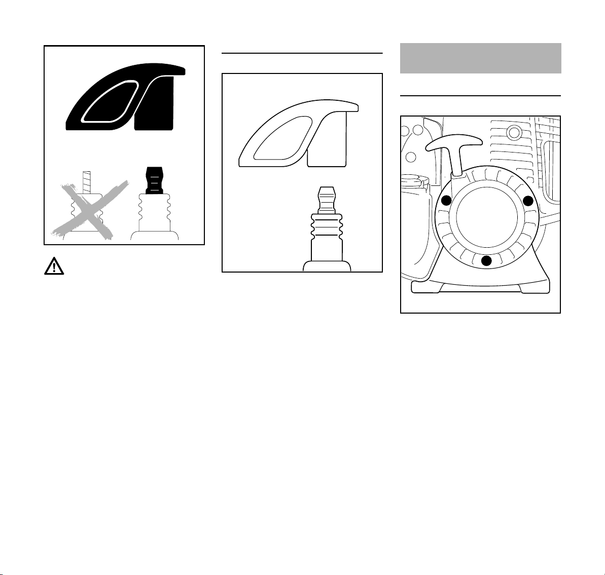
Warning!
To reduce the risk of fire and burn injury,
use only spark plugs authorized by
STIHL. Always press spark plug boot (1)
snugly onto spark plug terminal (2) of
the proper size. (Note: If terminal has
detachable SAE adapter nut, it must be
attached.) A loose connection between
spark plug boot and ignition wire connector in the boot may create arcing that
could ignite combustible fumes and
cause a fire.
Installing the spark plug
N Screw the spark plug (3) into the
cylinder and fit the boot (2) (press it
down firmly).
Replacing the Starter Rope
and Rewind Spring
Replacing the Starter Rope
N Push the slide control in direction of
arrow h – to STOP-0.
N Take out the screws (1).
N Remove the starter cover (2) from
the housing.
22
KM 90 R
Page 25

English
4
3
5
249BA013 KN
249BA014 KN
6
249BA015 KN
4
3
5
249BA013 KN
N Ease the spring clip (3) off the
starter post.
N Remove the rope rotor with
washer (4) and pawl (5).
N Remove the remaining rope from
the rotor and starter grip.
KM 90 R
N Tie a simple overhand knot in the
new rope and then thread it through
the top of the grip and the rope
bushing (6).
N Thread the rope through the rotor
and secure it with a simple
overhand knot.
N Coat the rope rotor bearing bore
with non-resinous oil.
N Slip the rotor over the starter post –
turn it back and forth to engage the
anchor loop of the rewind spring.
N Refit the pawl (5) in the rotor.
N Fit the washer (4) on the starter
post.
N Use a screwdriver or suitable pliers
to fit the spring clip (3) on the starter
post and over the pawl's peg – the
spring clip must point
counterclockwise – as shown in the
illustration.
N Go to "Tensioning the Rewind
Spring".
Replacing a broken rewind spring
N Remove the rope rotor as described
in chapter on "Replacing the starter
rope".
23
Page 26

English
249BA018 KN
249BA016 KN
The bits of spring may still be
under tension and could fly apart
when you take them out of the
housing. To reduce the risk of
injury, wear face protection and
work gloves.
N Remove the spring housing and
pieces of spring.
N Lubricate the new spring with a few
drops of non-resinous oil.
N Position the new spring housing,
bottom plate facing up, against the
cutouts (arrows).
N Push the spring housing into the
starter cover.
N Reinstall the rope rotor – then go to
"Tensioning the Rewind Spring".
N If the spring pops out of the spring
housing and uncoils: Refit it
counterclockwise, starting outside
and working inwards.
Tensioning the rewind spring
N Make a loop in the unwound starter
rope and use it to turn the rope rotor
six full revolutions in the direction of
the arrow.
N Hold the rotor steady. Pull out and
straighten the twisted rope.
N Let go of the rotor.
N Release the rope slowly so that it
winds onto the rotor. The starter grip
must locate firmly in the rope
bushing. If the grip droops to one
side: Add one more turn on the rope
rotor to increase spring tension.
N When the starter rope is fully
extended it must still be possible to
rotate the rotor another half turn. If
this is not the case, the spring is
overtensioned and could break.
Take one turn of the rope off the
rotor.
N Fit the starter cover on the housing.
N Tighten down the screws firmly.
24
KM 90 R
Page 27

Storing the Machine
For periods of 3 months or longer
N Drain and clean the fuel tank in a
well ventilated area.
N Dispose of fuel properly in
accordance with local
environmental requirements.
N Run the engine until the carburetor
is dry – this helps prevent the
carburetor diaphragms sticking
together.
N Thoroughly clean the machine –
pay special attention to the cylinder
fins and air filter.
N Remove, clean and inspect the
working tool.
N Store the machine in a dry, high or
locked location, out of the reach of
children and other unauthorized
persons.
English
KM 90 R
25
Page 28

English
Maintenance and Care
The following maintenance intervals apply in normal operating conditions. The specified intervals must be shortened accordingly when working for longer than normal
or under difficult cutting conditions (extensive dust, etc.).
before starting work
at the end of work and/or
daily
whenever tank is refilled
weekly
monthly
yearly
if faulty
if damaged
as required
Complete machine
Control handle check operation XX
Air filter
Fuel pick-up body in fuel tank
Fuel tank clean XX
Carburetor
Spark plug
Intake port for cooling air
Valve clearance
Combustion chamber
Spark arresting screen in muffler
Visual inspection (condition, leaks) XX
clean X
clean XX
replace X
Have checked by a specialist dealer
have them replaced by a specialist
1)
dealer
Check idle adjustment, the working tool
must not turn
Set idle speed X
Set electrode gap X
replace after every 100 hours of
operation
Visual inspection X
clean X
Check and adjust if necessary, one time
after 139 hours of operation, by servicing dealer
Decarbonize after 139 hours of operation, subsequently after every 150 hours
of operation
check XX
Clean or replace XX
1)
1)
XX
X
XXX
X
X
26
KM 90 R
Page 29

The following maintenance intervals apply in normal operating conditions. The specified intervals must be shortened accordingly when working for longer than normal
or under difficult cutting conditions (extensive dust, etc.).
before starting work
at the end of work and/or
daily
whenever tank is refilled
weekly
monthly
yearly
if faulty
All accessible screws, nuts and bolts (not
adjusting screws)
Antivibration elements
Safety information sticker replace X
1)
STIHL recommends STIHL servicing dealers
retighten X
check XXX
have them replaced by a specialist
1)
dealer
if damaged
X
English
as required
KM 90 R
27
Page 30

English
11
16
13
9
7
14
1
3
4
17
18
8
10
463BA004 KN
#
2
5
6
12
15
Main Parts
1 Fuel Filler Cap
2 Carburetor Adjusting Screws
3 Fuel Pump
4 Starter Grip
5 Muffler with Spark Arresting Screen
6 Coupling Sleeve
7 Wing Screw
8 Loop Handle
9 Barrier Bar
10 Carrying Ring
11 Slide Control
12 Throttle Trigger Lockout
13 Throttle Trigger
14 Spark Plug Boot
15 Choke Knob
16 Air Filter Cover
17 Fuel Tank
18 Machine Support
# Serial Number
28
KM 90 R
Page 31

English
Definitions
1 Fuel Filler Cap
For closing the fuel tank.
2 Carburetor Adjusting Screws
For tuning the carburetor.
3Fuel Pump
Provides additional fuel feed for a
cold start.
4 Starter Grip
The grip of the pull starter, for
starting the engine.
5 Muffler with Spark Arresting
Screen
Muffler reduces exhaust noises and
diverts exhaust gases away from
operator.
Spark arresting screen is designed
to reduce the risk of fire.
6 Coupling Sleeve
Connects drive tube to lower part of
drive tube (stub shaft).
7Wing Screw
Secures lower part of the drive tube
(stub shaft).
8 Loop Handle
For easy control of machine during
cutting work.
9 Barrier Bar
Helps keep user's feet and legs
clear of the cutting attachment.
10 Carrying Ring
Connects the unit to the harness.
11 Slide Control
For starting throttle, run and stop.
Keeps the choke partially open
during starting and switches off the
ignition to stop the engine.
12 Throttle Trigger Lockout
Must be depressed before the
throttle trigger can be activated.
13 Throttle Trigger
Controls the speed of the engine.
14 Spark Plug Boot
Connects the spark plug with the
ignition lead.
15 Choke Knob
Eases engine starting by enriching
mixture.
16 Air Filter Cover
Covers and protects the air filter
element.
17 Fuel Tank
For fuel and oil mixture.
18 Machine Support
For resting machine on the ground.
Specifications
EPA / CEPA
The Emission Compliance Period
referred to on the Emissions
Compliance Label indicates the number
of operating hours for which the engine
has been shown to meet Federal
emission requirements.
Category
A = 300 hours
B = 125 hours
C = 50 hours
CARB
The Emission Compliance Period used
on the CARB-Air Index Label indicates
the terms:
Extended = 300 hours
Intermediate = 125 hours
Moderate = 50 hours
Engine
STIHL one-cylinder, four-stroke engine
with mixture lubrication
KM 90 R
29
Page 32

English
Displacement: 1.73 cu.in
(28.4 cm
Bore: 1.5 in (38 mm)
Stroke: 0.98in (25mm)
Engine power to
ISO 8893:
Idle speed: 2,800 rpm
Cut-off speed (nomi-
nal value): 10,500 rpm
Valve clearance
Inlet valve: 0.004 in
Exhaust valve: 0.004 in
Ignition system
Electronic magneto ignition
Spark plug
(suppressed): Bosch USR 7AC
Electrode gap: 0.02 in (0.5 mm)
Fuel system
1.3 bhp (0.95 kW)
at 7000 rpm
(0.10 mm)
(0.10 mm)
3
)
Special Accessories Maintenance and Repairs
Contact your STIHL dealer for
information regarding special
accessories that may be available for
your product.
Users of this unit should carry out only
the maintenance operations described
in this manual. Other repair work may be
performed only by authorized STIHL
service shops.
Warranty claims following repairs can be
accepted only if the repair has been
performed by an authorized STIHL
servicing dealer using original STIHL
replacement parts.
Original STIHL parts can be identified by
the STIHL part number, the {
logo and, in some cases, by the STIHL
parts symbol K. The symbol may
appear alone on small parts.
All position diaphragm carburetor with
integral fuel pump
Fuel tank capacity: 18.0 fl.oz
(0.53 l)
Weight
without fuel. without KombiTool:
KM 90 R 9.9 lb (4.5 kg)
30
KM 90 R
Page 33

English
STIHL Incorporated
Federal Emission Control
Warranty Statement
Not for California
Your Warranty Rights and
Obligations
The U.S. Environmental Protection
Agency (EPA) and STIHL Incorporated
are pleased to explain the Emission
Control System Warranty on your
equipment type engine. In the U.S. new
1997 and later model year small off-road
equipment engines must be designed,
built and equipped, at the time of sale, to
meet the U.S. EPA regulations for small
non road engines. The equipment
engine must be free from defects in
materials and workmanship which
cause it to fail to conform with U.S. EPA
standards for the first two years of
engine use from the date of sale to the
ultimate purchaser.
STIHL Incorporated must warrant the
emission control system on your small
off-road engine for the period of time
listed below provided there has been no
abuse, neglect or improper maintenance
of your small off-road equipment engine.
Your emission control system includes
parts such as the carburetor and the
ignition system. Also included may be
hoses, and connectors and other
emission-related assemblies.
Where a warrantable condition exists,
STIHL Incorporated will repair your
small off-road equipment engine at no
cost to you, including diagnosis (if the
diagnostic work is performed at an
authorized dealer), parts, and labor.
Manufacturer's Warranty Coverage
In the U.S., 1997 and later model year
small off-road equipment engines are
warranted for two years. If any emissionrelated part on your engine is defective,
the part will be repaired or replaced by
STIHL Incorporated free of charge.
Owner's Warranty Responsibilities
As the small off-road equipment engine
owner, you are responsible for the
performance of the required
maintenance listed in your instruction
manual. STIHL Incorporated
recommends that you retain all receipts
covering maintenance on your small offroad equipment engine, but STIHL
Incorporated cannot deny warranty
solely for the lack of receipts or for your
failure to ensure the performance of all
scheduled maintenance.
Any replacement part or service that is
equivalent in performance and durability
may be used in non-warranty
maintenance or repairs, and shall not
reduce the warranty obligations of the
engine manufacturer.
As the small off-road equipment engine
owner, you should be aware, however,
that STIHL Incorporated may deny you
warranty coverage if your small off-road
equipment engine or a part has failed
due to abuse, neglect, improper
maintenance or unapproved
modifications.
You are responsible for presenting your
small off-road equipment engine to a
STIHL service center as soon as a
problem exists. The warranty repairs will
be completed in a reasonable amount of
time, not to exceed 30 days.
If you have any questions regarding your
warranty rights and responsibilities,
please contact a STIHL customer
service representative at 1-800-4678445 or you can write to
STIHL Inc.,
536 Viking Drive, P.O. Box 2015,
Virginia Beach, VA 23450-2015
www.stihlusa.com
Coverage by STIHL Incorporated
STIHL Incorporated warrants to the
ultimate purchaser and each
subsequent purchaser that your small
off-road equipment engine will be
designed, built and equipped, at the time
of sale, to meet all applicable
regulations. STIHL Incorporated also
warrants to the initial purchaser and
each subsequent purchaser that your
engine is free from defects in materials
and workmanship which cause the
engine to fail to conform with applicable
regulations for a period of two years.
Warranty Period
The warranty period will begin on the
date the utility equipment engine is
purchased by the initial purchaser and
you have signed and sent back the
warranty card to STIHL.
If any emission-related part on your
engine is defective, the part will be
replaced by STIHL Incorporated at no
cost to the owner. Any warranted part
which is not scheduled for replacement
as required maintenance, or which is
scheduled only for regular inspection to
KM 90 R
31
Page 34

English
the effect of "repair or replace as
necessary" will be warranted for the
warranty period. Any warranted part
which is scheduled for replacement as
required maintenance will be warranted
for the period of time up to the first
scheduled replacement point for that
part.
Diagnosis
You, as the owner, shall not be charged
for diagnostic labor which leads to the
determination that a warranted part is
defective. However, if you claim
warranty for a component and the
machine is tested as non-defective,
STIHL Incorporated will charge you for
the cost of the emission test. Mechanical
diagnostic work will be performed at an
authorized STIHL servicing dealer.
Emission test may be performed either
at STIHL Incorporated or at any
independent test laboratory.
Warranty Work
STIHL Incorporated shall remedy
warranty defects at any authorized
STIHL servicing dealer or warranty
station. Any such work shall be free of
charge to the owner if it is determined
that a warranted part is defective.
Any manufacturer-approved or
equivalent replacement part may be
used for any warranty maintenance or
repairs on emission-related parts and
must be provided without charge to the
owner. STIHL Incorporated is liable for
damages to other engine components
caused by the failure of a warranted part
still under warranty.
The following list specifically defines the
emission-related warranted parts:
– Air Filter
– Carburetor
– Fuel Pump
– Choke (Cold Start Enrichment
System)
– Control Linkages
– Intake Manifold
– Magneto or Electronic Ignition
System (Ignition Module)
– Spark Plug
– Catalytic Converter (if applicable)
– Fuel Tank
– Fuel Cap
– Fuel Line
– Fuel Line Fittings
– Clamps
– Fasteners
Where to make a Claim for Warranty
Service
Bring the product to any authorized
STIHL servicing dealer and present the
signed warranty card.
Maintenance Requirements
The maintenance instructions in this
manual are based on the application of
the recommended 2-stroke fuel-oil
mixture (see also instruction "Fuel").
Deviations from this recommendation
regarding quality and mixing ratio of fuel
and oil may require shorter maintenance
intervals.
Limitations
This Emission Control Systems
Warranty shall not cover any of the
following:
N repair or replacement required
because of misuse, neglect or lack
of required maintenance,
N repairs improperly performed or
replacements not conforming to
STIHL Incorporated specifications
that adversely affect performance
and/or durability, and alterations or
modifications not recommended or
approved in writing by STIHL
Incorporated,
and
N replacement of parts and other
services and adjustments
necessary for required maintenance
at and after the first scheduled
replacement point.
32
KM 90 R
Page 35

English
STIHL Incorporated
California Exhaust and
Evaporative Emissions
Control Warranty
Statement
For California only
Your Warranty Rights and
Obligations
The California Air Resources Board
(CARB) and STIHL Incorporated are
pleased to explain the Emission Control
System Warranty on your 2007 and later
small off-road equipment engine.
In California, new equipment that uses
small off-road engines must be
designed, built, and equipped to meet
the State's stringent anti-smog
standards. STIHL Incorporated must
warrant the emissions control system on
your small off-road engine for the period
listed below provided there has been no
abuse, neglect or improper maintenance
of your small off-road engine.
Your emissions control system may
include parts such as:
Air Filter, Carburetor, Fuel Pump, Choke
(Cold Start Enrichment System), Control
Linkages, Intake Manifold, Magneto or
Electronic Ignition System (Ignition
Module), Spark Plug, Catalytic
Converter (if applicable), Fuel Tank,
Fuel Cap, Fuel Line, Fuel Line Fittings,
Clamps, Fasteners.
Where a warrantable condition exists,
STIHL Incorporated will repair your
small off-road equipment engine at no
cost to you including diagnosis, parts
and labor.
Manufacturer’s Warranty
Responsibilities
This emissions control system is
warranted for two years in California. If
any emissions-related part on your
equipment is defective, the part will be
repaired or replaced by STIHL
Incorporated free of charge.
Owner’s Warranty Responsibilities
As the small off-road equipment engine
owner, you are responsible for
performance of the required
maintenance listed in your instruction
manual. STIHL Incorporated
recommends that you retain all receipts
covering maintenance on your small offroad equipment engine, but STIHL
Incorporated cannot deny warranty
solely for the lack of receipts or your
failure to ensure the performance of all
scheduled maintenance.
As the small off-road equipment engine
owner, you should however be aware
that STIHL Incorporated may deny you
warranty coverage if your small off-road
equipment engine or a part has failed
due to abuse, neglect, or improper
maintenance or unapproved
modifications.
You are responsible for presenting your
small off-road equipment engine to a
STIHL servicing dealer as soon as the
problem exists. The warranty repairs
should be completed in a reasonable
amount of time, not to exceed 30 days. If
you have any questions regarding your
warranty rights and responsibilities,
please contact a STIHL customer
service representative at 1-800-4678445 or you can write to
STIHL Inc., 536 Viking Drive,
P.O. Box 2015,
Virginia Beach, VA 23450-2015.
Coverage by STIHL Incorporated
STIHL Incorporated warrants to the
ultimate purchaser and each
subsequent purchaser that your small
off-road equipment engine is designed,
built and equipped, at the time of sale, to
meet all applicable emission
regulations.
STIHL Incorporated also warrants to the
initial purchaser and each subsequent
purchaser that your engine is free from
defects in materials and workmanship
which cause the engine to fail to conform
to applicable emission regulations for a
period of two years.
Defects Warranty Period
The warranty periods will begin on the
date the utility equipment engine is
purchased by the initial purchaser. If any
emission-related part on your engine is
defective, the part will be replaced by
STIHL Incorporated at no cost to the
owner.
Add-on or modified parts that are not
exempted by CARB may not be used.
The use of any non exempted add-on or
modified parts will be grounds for
disallowing a warranty claim. STIHL
Incorporated will not be liable to warrant
failures of warranted parts caused by the
use of a non exempted add-on or
modified part.
KM 90 R
33
Page 36

English
The warranty on emissions-related parts
will be interpreted as follows:
1. Any warranted part that is not
scheduled for replacement as
required maintenance in the written
instructions required in the
Emission Warranty Parts List (see
below) must be warranted for the
warranty period defined in
Subsection COVERAGE BY STIHL
INCORPORATED, see above. If
any such part fails during the period
of warranty coverage, it must be
repaired or replaced by the
manufacturer according to
Subsection (4) below. Any such part
repaired or replaced under the
warranty must be warranted for the
remaining warranty period.
2. Any warranted part that is
scheduled only for regular
inspection in the written instructions
required by the Emission Warranty
Parts List (see below) must be
warranted for the warranty period
defined in Subsection COVERAGE
BY STIHL INCORPORATED, see
above. A statement in such written
instructions to the effect of "repair or
replace as necessary" will not
reduce the period of warranty
coverage. Any such part repaired or
replaced under warranty must be
warranted for the remaining
warranty period.
3. Any warranted part that is
scheduled for replacement as
required maintenance in the written
instructions required by the
Emission Warranty Parts List (see
below) must be warranted for the
period of time prior to the first
scheduled replacement point for
that part. If the part fails prior to the
first scheduled replacement, the
part must be repaired or replaced by
the engine manufacturer according
to Subsection (4) below. Any such
part repaired or replaced under
warranty must be warranted for the
remainder of the period prior to the
first scheduled replacement point
for the part.
4. Repair or replacement of any
warranted part under the warranty
must be performed at a warranty
station at no charge to the owner.
5. Notwithstanding the provisions of
Subsection (4) above, warranty
services or repairs will be provided
at all manufacturer distribution
centers that are authorized to
service the subject engines.
6. The owner must not be charged for
diagnostic labor that leads to the
determination that a warranted part
is in fact defective, provided that
such diagnostic work is performed
at a warranty station.
Warranty Work
STIHL Incorporated shall remedy
warranty defects at any authorized
STIHL servicing dealer or warranty
station. Any such work shall be free of
charge to the owner if it is determined
that a warranted part is defective. Any
manufacturer approved or equivalent
replacement part may be used for any
warranty maintenance or repairs on
emission-related parts and must be
provided without charge to the owner.
STIHL Incorporated is liable for
damages to other engine components
caused by the failure of a warranted part
still under warranty.
Emission Warranty Parts List
Air Filter, Carburetor, Fuel Pump, Choke
(Cold Start Enrichment System), Control
Linkages, Intake Manifold, Magneto or
Electronic Ignition System (Ignition
Module), Spark Plug, Catalytic
Converter (if applicable), Fuel Tank,
Fuel Cap, Fuel Line, Fuel Line Fittings,
Clamps, Fasteners
Where to make a Claim for Warranty
Service
Bring the STIHL product to any
authorized STIHL servicing dealer and
present the signed STIHL product
registration card, or the print-out of the
electronic product registration.
Limitations
The repair or replacement of any
warranted part otherwise eligible for
warranty coverage may be excluded
from such warranty coverage if STIHL
Incorporated demonstrates that the
STIHL product has been abused,
neglected, or improperly maintained,
and that such abuse, neglect, or
improper maintenance was the direct
cause of the need for repair or
replacement of the part. That
notwithstanding, any adjustment of a
component that has a factory installed,
and properly operating, adjustment
limiting device is still eligible for warranty
coverage.
34
KM 90 R
Page 37

English
Trademarks
STIHL Registered Trademarks
®
STIHL
{
K
The color combination orange-grey
(U.S. Registrations #2,821,860;
#3,010,057, #3,010,058, #3,400,477;
and #3,400,476)
®
4-MIX
AUTOCUT
EASYSTART
FARM BOSS
iCademy
OILOMATIC
STIHL Cutquik
STIHL DUROMATIC
STIHL Quickstop
STIHL ROLLOMATIC
STIHL WOOD BOSS
TIMBERSPORTS
WOOD BOSS
YARD BOSS
®
®
®
®
®
®
®
®
®
®
®
®
®
Some of STIHL’s Common Law
Trademarks
BioPlus™
Easy2Start™
EasySpool™
ElastoStart™
Ematic™
FixCut™
HT Plus™
IntelliCarb™
Master Control Lever™
Micro™
Pro Mark™
Quad Power™
Quiet Line™
STIHL Compact™
STIHL HomeScaper Series™
STIHL Interchangeable Attachment
Series™
STIHL M-Tronic™
STIHL Magnum™
STIHL MiniBoss™
STIHL MotoPlus 4™
STIHL Multi-Cut HomeScaper Series™
STIHL OUTFITTERS™
STIHL PICCO™
STIHL PolyCut™
STIHL PowerSweep™
STIHL Precision Series™
STIHL Protech™
STIHL RAPID™
STIHL SuperCut™
STIHL Territory™
TapAction™
TrimCut™
This listing of trademarks is subject to
change.
Any unauthorized use of these
trademarks without the express written
consent of
ANDREAS STIHL AG & Co. KG,
Waiblingen is strictly prohibited.
KM 90 R
35
Page 38

English
36
KM 90 R
Page 39

Contenido
español / EE.UU
Sistema KombiSystem 38
Acerca de este manual de
instrucciones 38
Medidas de seguridad y técnicas
de manejo 39
Herramientas KombiTool
aprobadas 48
Montaje del mango tórico 49
Ajuste del cable del acelerador 50
Manual de instrucciones originalImpreso en papel libre de cloro.
Motor 4-MIX 50
Combustible 50
Llenado de combustible 52
Arranque / parada del motor 53
Instrucciones para el uso 56
Limpieza del filtro de aire 57
Gestión del motor 57
Ajuste del carburador 57
Chispero en el silenciador 59
Bujía 60
Sustitución de la cuerda de
arranque y del resorte de
rebobinado 61
Almacenamiento de la máquina 63
Las tintas contienen aceites vegetales, el papel es reciclable.
Información para mantenimiento 64
Componentes importantes 66
Especificaciones 67
Accesorios especiales 68
Información de reparación 68
Declaración de garantía de STIHL
Incorporated sobre sistemas de
control de emisiones según normas
Federales 69
Declaración de garantía de STIHL
Incorporated sobre el control de
emisiones de gases de escape y
emisiones por evaporación para el
Estado de California 71
Marcas comerciales 74
Permita que solamente las personas
que comprenden la materia tratada en
los manuales del motor KombiEngine y
del accesorio KombiTool manejen esta
herramienta motorizada combinada.
Para obtener el rendimiento y
satisfacción máximos de la herramienta
motorizada STIHL, es importante que
lea, comprenda y respete las medidas
de seguridad y las instrucciones de uso
y mantenimiento dadas en el capítulo
"Medidas de seguridad y técnicas de
uso", antes de usar su herramienta
motorizada. Para obtener información
adicional, visite www.stihlusa.com.
Comuníquese con el concesionario o
distribuidor de STIHL si no se entiende
alguna de las instrucciones dadas en los
dos manuales.
Advertencia!
Dado que este motor KombiEngine es
el motor para una herramienta motorizada que funciona a gran velocidad, es
necesario tomar algunas medidas
especiales de seguridad para reducir el
riesgo de lesiones personales. El uso
descuidado o inadecuado puede causar
lesiones graves e incluso mortales.
{
© ANDREAS STIHL AG & Co. KG, 2011
0458-465-8621-B. M11.F11.CP.
0000000811_006_EA
KM 90 R
37
Page 40

español / EE.UU
.
.
.
.
002BA442 KN
+
+
Sistema KombiSystem
Con el sistema KombiSystem de STIHL,
varios motores KombiEngine y
accesorios KombiTool pueden
combinarse para formar una
herramienta motorizada. En este
manual de instrucciones la unidad
formada por el motor KombiEngine y la
herramienta KombiTool se identifica
como la herramienta motorizada.
Por lo tanto, para esta herramienta
motorizada es necesario usar juntos los
manuales de instrucciones para el motor
KombiEngine y la herramienta
KombiTool.
Siempre lea y entienda los dos
manuales de instrucciones antes de
usar la herramienta motorizada por
primera vez y guarde los mismos en un
lugar seguro para referencia futura.
Acerca de este manual de
instrucciones
Pictogramas
Todos los pictogramas que se
encuentran fijados o grabados en la
máquina se explican en este manual.
Según el modelo, los pictogramas
siguientes pueden aparecer en su
máquina.
Tanque de combustible
que contiene la mezcla
de combustible y aceite
Presione para accionar la
válvula de
descompresión
Bomba de combustible
manual
Presione para accionar la
bomba manual de
combustible
Orificio de llenado para
lubricante de engranajes
Toma de aire para modo
de verano
Toma de aire para modo
de invierno
Calentador de manillar
Símbolos en el texto
Muchas de las instrucciones de uso y
seguridad vienen acompañadas de
ilustraciones.
Los pasos individuales o
procedimientos descritos en el manual
pueden estar señalados en diferentes
maneras:
N Se usa un punto para denotar un
paso o procedimiento.
Una descripción de un paso o
procedimiento que se refiere
directamente a una ilustración puede
contener números de referencia que
aparecen en la ilustración. Ejemplo:
N Suelte el tornillo (1).
N Palanca (2) ...
Además de las instrucciones de uso, en
este manual pueden encontrarse
párrafos a los que usted debe prestar
atención especial. Tales párrafos están
marcados con los símbolos y las
palabras identificadoras que se
describen a continuación.
¡Peligro!
Indica un riesgo inminente de lesiones
graves o mortales.
Advertencia!
Identifica una situación de peligro que,
al no evitarse, puede resultar en lesiones graves o mortales.
38
KM 90 R
Page 41

español / EE.UU
¡Precaución!
Indica el riesgo de daños a la propiedad, incluyendo a la máquina o sus
componentes.
Mejoramientos técnicos
La filosofía de STIHL es mejorar
continuamente todos sus productos.
Como resultado de ello, periódicamente
se introducen cambios de diseño y
mejoras. Por lo tanto, es posible que
algunos cambios, modificaciones y
mejoras no se describen en este
manual. Si las características de
funcionamiento o la apariencia de su
máquina difieren de las descritas en
este manual, comuníquese con el
concesionario STIHL para obtener la
ayuda que requiera.
Medidas de seguridad y
técnicas de manejo
Dado que este motor
KombiEngine es el motor
para una herramienta
motorizada que funciona
a gran velocidad, es
necesario tomar medidas especiales de
seguridad para reducir el
riesgo de lesiones
personales.
Es importante que usted
lea, comprenda bien y
respete las siguientes
advertencias y medidas
de seguridad. Lea periódicamente los manuales
de instrucciones y las
precauciones de seguridad de su motor Kombi y
accesorio Kombi. El uso
descuidado o inadecuado
puede causar lesiones
graves o incluso
mortales.
Pida a su concesionario STIHL que le
enseñe el manejo de la herramienta
motorizada. Respete todas las
disposiciones, reglamentos y normas de
seguridad locales del caso.
Advertencia!
No preste ni alquile nunca su herramienta motorizada sin entregar los
manuales de instrucciones. Asegúrese
que todas las personas que utilicen la
máquina lean y comprendan la información contenida en estos manuales.
Utilice su herramienta motorizada
solamente para las aplicaciones
descritas en el manual de instrucciones
del accesorio KombiTool que está
usando.
Advertencia!
No debe usarse para ningún otro propósito ya que el uso indebido puede
resultar en lesiones personales o daños
a la propiedad, incluso daños de la
máquina.
Advertencia!
Nunca se debe permitir a los niños que
usen esta herramienta motorizada. No
se debe permitir la proximidad de otros,
especialmente niños y animales, donde
se esté utilizando la máquina.
Advertencia!
Para reducir el riesgo de ocasionar
lesiones a las personas en la cercanía y
daños a la propiedad, nunca deje la
herramienta motorizada en marcha
desatendida. Cuando no está en uso
(por ejemplo durante el descanso), apáguela y asegúrese de que las personas
no autorizadas no puedan usarla.
Las medidas de seguridad y avisos
contenidos en este manual se refieren al
uso de todas las herramientas
motorizadas STIHL. Los distintos
modelos pueden contar con piezas y
controles diferentes. Vea la sección
correspondiente de sus manuales de
instrucciones del motor KombiEngine y
accesorio KombiTool para tener una
descripción de los controles y la función
de los componentes de su modelo.
KM 90 R
39
Page 42

español / EE.UU
No limpie la máquina con una lavadora
a presión. El chorro fuerte de agua
puede dañar las piezas de la máquina.
El uso seguro de un motor KombiEngine
atañe a
1. el operador
2. la herramienta motorizada
3. el uso de la herramienta motorizada
EL OPERADOR
Condición física
Usted debe estar en buenas
condiciones físicas y psíquicas y no
encontrarse bajo la influencia de
ninguna sustancia (drogas, alcohol,
etc.) que le pueda restar visibilidad,
destreza o juicio. No maneje esta
máquina cuando está fatigado.
Advertencia!
Esté alerta. Si se cansa, tómese un descanso. El cansancio puede provocar
una pérdida del control. El uso de cualquier herramienta motorizada es
fatigoso. Si usted padece de alguna
dolencia que pueda ser agravada por la
fatiga, consulte a su médico antes de
utilizar esta máquina.
Advertencia!
El uso prolongado de una herramienta
motorizada (u otras máquinas) expone
al operador a vibraciones que pueden
provocar el fenómeno de Raynaud
(dedos blancos) o el síndrome del túnel
carpiano.
Estas condiciones reducen la capacidad
de las manos de sentir y regular la
temperatura, producen entumecimiento
y ardor y pueden provocar trastornos
nerviosos y circulatorios, así como
necrosis de los tejidos.
No se conocen todos los factores que
contribuyen a la enfermedad de
Raynaud, pero el clima frío, el fumar y
las enfermedades o condiciones físicas
que afectan los vasos sanguíneos y la
circulación de la sangre, como asimismo
los niveles altos de vibración y períodos
prolongados de exposición a la
vibración son mencionados como
factores en el desarrollo de la
enfermedad de Raynaud. Por lo tanto,
para reducir el riesgo de la enfermedad
de dedos blancos y del síndrome del
túnel carpiano, sírvase notar lo
siguiente:
– La mayor parte de las herramientas
motorizadas de STIHL se ofrecen
con un sistema antivibración ("AV")
cuyo propósito es reducir la
transmisión de las vibraciones
creadas por la máquina a las manos
del operador. Se recomienda el uso
del sistema AV a aquellas personas
que utilizan herramientas
motorizadas en forma constante y
regular.
– Use guantes – no durante el uso del
la herramienta KombiTool BG-KM –
y mantenga las manos abrigadas.
– Mantenga el sistema AV en buen
estado. Una herramienta
motorizada con los componentes
flojos o con elementos AV dañados
o desgastados también tendrá
tendencia a tener niveles más altos
de vibración.
– Agarre firmemente los mangos en
todo momento, pero no los apriete
con fuerza constante y excesiva.
Tómese descansos frecuentes.
Todas las precauciones antes
mencionadas no le garantizan que va a
estar totalmente protegido contra la
enfermedad de Raynaud o el síndrome
del túnel carpiano. Por lo tanto, los
operadores constantes y regulares
deben revisar con frecuencia el estado
de sus manos y dedos. Si aparece
alguno de los síntomas arriba
mencionados, consulte inmediatamente
al médico.
Advertencia!
El sistema de encendido de la máquina
STIHL produce un campo electromagnético de intensidad muy baja. El mismo
puede interferir con algunos tipos de
marcapasos. Para reducir el riesgo de
lesiones graves o mortales, las personas portadoras de marcapasos deben
consultar a sus médicos y al fabricante
del marcapasos antes de usar esta
máquina.
40
KM 90 R
Page 43

español / EE.UU
Vestimenta adecuada
Advertencia!
Para reducir el riesgo de lesiones el
operador debe usar el equipo protector
adecuado.
Advertencia!
El ruido de la herramienta motorizada puede
dañar los oídos. Siempre
use amortiguadores del
ruido (tapones u oreje-
ras) para protegerse los
oídos. Los usuarios constantes y regulares deben someterse con frecuencia a
un examen o control auditivo.
Esté especialmente alerta y tenga
cuidado cuando se usa protectores de
oídos, ya que los mismos reducen la
posibilidad de oír señales de
advertencia (gritos, alarmas, etc.).
Para instrucciones adicionales acerca
de la ropa adecuada, vea las
precauciones de seguridad, en el
manual de instrucciones del accesorio
KombiTool que está usando.
LA HERRAMIENTA MOTORIZADA
Para las ilustraciones y definiciones de
los componentes de la herramienta
motorizada, vea el capítulo "Piezas
principales y controles".
Advertencia!
Nunca modifique, de ninguna manera,
esta herramienta motorizada. Utilice
únicamente los accesorios suministrados por STIHL o expresamente
autorizados por STIHL para usarse con
el modelo específico de motor KombiEngine de STIHL. Si bien es posible
conectar a la herramienta motorizada
de STIHL ciertos accesorios no autorizados, su uso puede ser, en la práctica,
extremadamente peligroso.
Si la máquina experimenta cargas
excesivas para las cuales no fue
diseñada (por ejemplo, impactos
severos o una caída), siempre
asegúrese de que la máquina esté en
buenas condiciones antes de seguir con
el trabajo. Inspeccione específicamente
la integridad del sistema de combustible
(ausencia de fugas) y asegúrese de que
los controles y dispositivos de seguridad
funcionen como es debido. No siga
manejando esta máquina si está
dañada. En caso de dudas, pida que el
concesionario de servicio de STIHL la
revise.
USO DE LA HERRAMIENTA
MOTORIZADA
Transporte de la herramienta
motorizada
Advertencia!
Antes de apoyar la herramienta motorizada en el suelo, siempre apague el
motor y asegúrese de que el accesorio
ha dejado de girar. Cuando transporte
la herramienta motorizada en un vehículo, sujétela firmemente para impedir
su vuelco, el derrame de combustible y
el daño a la herramienta motorizada.
Combustible
La herramienta motorizada STIHL utiliza
una mezcla de aceite-gasolina como
combustible (vea el capítulo
"Combustible" en el manual del
propietario).
Advertencia!
La gasolina es un combustible muy inflamable.
Si se derrama y arde a
causa de una chispa u
otra fuente de ignición,
puede provocar un
incendio y quemaduras graves o daños
a la propiedad. Tenga sumo cuidado
cuando manipule gasolina o la mezcla
de combustible. No fume cerca del combustible o la herramienta motorizada, ni
acerque ningún fuego o llama a ellos.
Puede escapar vapor inflamable del sistema de combustible.
KM 90 R
41
Page 44

español / EE.UU
001BA220 KN
Instrucciones para el llenado de
combustible
Advertencia!
Para reducir el riesgo de lesiones graves causadas por quemaduras, nunca
intente abastecer la máquina con combustible sin que el operador se haya
despojado de la misma.
Advertencia!
Cargue de combustible su herramienta
motorizada en lugares al aire libre bien
ventilados. Siempre apague el motor y
deje que se enfríe antes de llenar de
combustible. Dependiendo del combustible utilizado, de las condiciones
climáticas y del sistema de ventilación
del tanque, es posible que se forme
vapor de gasolina a presión dentro del
tanque de combustible.
Para reducir el riesgo de quemaduras,
así como otras lesiones corporales
ocasionadas por los escapes de vapor
de gasolina y otras emanaciones, quite
la tapa de llenado de combustible de la
herramienta motorizada
cuidadosamente de modo que la
presión que se pueda haber acumulado
en el tanque se disipe lentamente.
Nunca quite la tapa de llenado de
combustible mientras el motor esté
funcionando.
Elija una superficie despejada para
llenar el tanque y aléjese 3 m (10 pies)
por lo menos del lugar en que lo haya
llenado antes de arrancar el motor.
Limpie todo el combustible derramado
antes de arrancar la máquina.
Advertencia!
Compruebe que no existen fugas de
combustible mientras
llena el tanque y durante
el funcionamiento de la
máquina. Si detecta
alguna fuga de combustible, no arranque el motor ni lo haga funcionar sin
antes reparar la fuga y limpiar el combustible derramado. Tenga cuidado de
no mancharse la ropa con combustible.
Si la mancha, cámbiesela
inmediatamente.
El tipo de tapa de llenado difiere con los
distintos modelos.
Tapa sin herramientas con
empuñadura
Advertencia!
Para reducir el riesgo de derramar combustible y provocar un incendio debido a
una tapa de combustible mal apretada,
coloque la tapa en la posición correcta y
apriétela en la boca de llenado del
tanque.
Para hacer esto con esta tapa STIHL,
levante la empuñadura en la parte
superior de la tapa hasta dejarla vertical
a un ángulo de 90°. Inserte la tapa en la
boca de llenado del tanque, alineando
las marcas de posición en la
empuñadura de la tapa y en la boca del
tanque. Utilice la empuñadura para
oprimir la tapa firmemente hacia abajo
mientras la gira en sentido horario hasta
que tope (aprox. un cuarto de vuelta).
Doble la empuñadura
dejándola a ras con la
parte superior de la tapa.
Sujete la tapa y compruebe que esté bien
apretada. Si la empuñadura no queda
completamente a ras con
la tapa y el tope de la
empuñadura no encaja
en la hendidura correspondiente de la abertura
de llenado, o si la tapa
está suelta en la boca de
llenado, la tapa no está
debidamente asentada ni
apretada y es necesario
repetir los pasos previamente descritos.
Tapa desalineada, dañada o rota
N Si la tapa no encaja completamente
en la abertura cuando se alinean las
marcas de posición y/o si la tapa no
se aprieta debidamente al girarla, la
base de la tapa puede haber girado
prematuramente (con relación a la
parte superior) hasta la posición
cerrada. Tal desalineación puede
ser resultado de la manipulación,
limpieza o un intento incorrecto de
apriete.
42
KM 90 R
Page 45

español / EE.UU
001BA227 KN
001BA226 KN
A izquierda: Base de la tapa en posi-
ción cerrada (con
espacio vacío)
A derecha: Base de la tapa correcta-
mente colocada para la
instalación
N Para volver a colocar la tapa en
posición abierta para instalarla,
gírela (con la empuñadura hacia
arriba) hasta que caiga
completamente en la abertura del
tanque. A continuación, gire la tapa
en sentido contrahorario hasta que
tope (aprox. 1/4 de vuelta) – esto
gira la base de la tapa a la posición
correcta. Luego gire la tapa en
sentido horario, cerrándola de
modo normal.
N Si aún no es posible apretar la tapa
de modo debido, la misma podría
estar averiada o rota; ponga la
máquina fuera de servicio de
inmediato y llévela a un
concesionario STIHL autorizado
para repararla.
Tapa roscada
Advertencia!
Las vibraciones de la
máquina pueden aflojar
una tapa de combustible
que ha quedado mal
apretada, o simplemente
soltarla y derramar combustible. Para reducir el riesgo de
derrames e incendio, apriete la tapa de
llenado de combustible a mano tan firmemente como sea posible.
Consulte también el capítulo
"Combustible" del Manual de
instrucciones para obtener información
adicional.
Antes de arrancar
Advertencia!
Siempre revise la herramienta motorizada para comprobar que está en
buenas condiciones y que funciona
correctamente antes de arrancarla, en
particular el gatillo de aceleración, el
bloqueo de gatillo de aceleración, el
interruptor de parada, el accesorio de
corte, el deflector y el arnés. El gatillo de
aceleración debe moverse libremente y
siempre debe regresar a la posición de
marcha en vacío por la acción de
resorte. Nunca intente modificar los
controles o los dispositivos de
seguridad.
Advertencia!
No maneje nunca una herramienta
motorizada que esté dañada, mal ajustada o mantenida o que no fue armada
completa y debidamente.
Advertencia!
Asegúrese de que el casquillo de la
bujía esté firmemente colocado – un
casquillo suelto puede crear un arco
voltaico y encender los vapores del
combustible, provocando un incendio.
Mantenga los mangos limpios y secos
en todo momento; es particularmente
importante mantenerlos libres de
humedad, aceite, combustible, grasa o
resinas para garantizar que la máquina
pueda empuñarse firmemente para
mantenerla bajo control seguro.
Arranque
Arranque el motor al aire libre, por lo
menos 3 m (10 pies) del lugar en que lo
haya llenado.
Para las instrucciones específicas de
arranque, vea la sección
correspondiente de los manuales del
motor y accesorio KombiTool. Coloque
la herramienta motorizada sobre suelo
firme u otra superficie sólida en un lugar
abierto. Mantenga el equilibrio y elija un
buen punto de apoyo para los pies.
KM 90 R
43
Page 46

español / EE.UU
002BA057 KN
Advertencia!
Para reducir el riesgo de lesiones
debido a la pérdida de control, esté
absolutamente seguro que la herramienta motorizada se encuentra lejos
de su cuerpo y de todas las obstrucciones y objetos, incluido el suelo, porque
al arrancar el motor acelerado, su velocidad será lo suficientemente rápida
para que el embrague se engrane y
haga funcionar la herramienta
motorizada.
Tan pronto arranque, accione
inmediatamente por un breve momento
el gatillo de aceleración para
desconectarlo de la posición de
arranque y permitir que el motor se
desacelere a la marcha en vacío.
Advertencia!
Su herramienta motorizada es una
máquina que debe ser manejada por
solamente una persona. No deje que
otras personas estén en el lugar de trabajo, aun durante el arranque.
Advertencia!
Para reducir el riesgo de sufrir lesiones
causadas por la pérdida de control, no
intente arrancar el motor de la herramienta "por lanzamiento".
Advertencia!
Cuando tire del mango de arranque, no
enrolle la cuerda de arranque alrededor
de la mano. No deje que el mango retroceda bruscamente, sino guíe la cuerda
de arranque para que se enrolle debidamente. Si no ejecuta este procedimiento
puede lastimarse la mano o los dedos y
también dañar el mecanismo de
arranque.
Vea también las precauciones de
seguridad de arranque en el manual de
instrucciones del accesorio KombiTool.
Ajustes importantes
Advertencia!
Para reducir el riesgo de lesiones personales debido a la pérdida de control o
al contacto con la herramienta motorizada en movimiento, no use una
herramienta cuyo ajuste de marcha en
vacío está mal regulado. Cuando la
velocidad de marcha en vacío está
correctamente regulada, la herramienta
no debe girar. Para instrucciones
acerca de cómo ajustar el régimen de
marcha en vacío, vea la sección correspondiente del manual de instrucciones.
Si no puede regular correctamente el
ralentí, pida a su concesionario STIHL
que revise la herramienta motorizada y
haga los ajustes o reparaciones
correspondientes.
Durante el trabajo
Sujeción y control de la herramienta
motorizada
Al trabajar, siempre sujete la máquina
firmemente con ambas manos en los
mangos. Cierre firmemente los dedos y
pulgares sobre los mangos.
La mano derecha debe sujetar el mango
trasero. Esto también corresponde a
personas zurdas.
Advertencia!
Para reducir el riesgo de lesiones causadas por la pérdida del control, nunca
trabaje sobre una escalera o cualquier
otra superficie de soporte poco seguro.
Condiciones de trabajo
Maneje y arranque su herramienta
motorizada solamente al aire libre en un
lugar bien ventilado. Manéjela
solamente en condiciones de buena
visibilidad y a la luz del día. Trabaje con
mucho cuidado.
44
KM 90 R
Page 47

español / EE.UU
Advertencia!
Tan pronto arranca, este
producto genera vapores
de escape tóxicos que
contienen productos químicos (tales como
hidrocarburos sin quemar
y monóxido del carbono, incluyendo el
benceno) considerados como causantes de enfermedades respiratorias,
cáncer, defectos de nacimiento u otra
toxicidad reproductora. Algunos de
estos gases (por ej., monóxido de carbono) pueden ser incoloros e inodoros.
Para reducir el riesgo de sufrir lesiones
graves o mortales por respirar gases
tóxicos, nunca haga funcionar la
máquina puertas adentro o en lugares
mal ventilados.
Advertencia!
La inhalación de ciertos polvos, especialmente los polvos orgánicos, tales
como el moho o polen, puede provocar
reacciones alérgicas o asmáticas en las
personas sensibles. La inhalación repetida o de grandes cantidades de polvo u
otros contaminantes del aire, especialmente los de partículas pequeñas
puede causar enfermedades respiratorias o de otro tipo. Controle el polvo en
su fuente, siempre que sea posible. Utilice buenas prácticas de trabajo, tal
como trabajar de manera que el viento
o el proceso de corte dirija el polvo producido por la herramienta motorizada
en sentido opuesto del operador.
Observe las recomendaciones emitidas
por EPA/OSHA/NIOSH y las asociaciones de trabajo y los sindicatos con
respecto al polvo ("materia particulada"). Cuando sea imposible eliminar
significativamente la inhalación del
polvo, es decir mantener el nivel cerca
del valor ambiente, el operador y las
personas que se encuentren en la cercanía siempre deberán usar un
respirador aprobado por NIOSH/MSHA
para el tipo de polvo presente en el
lugar.
Instrucciones de manejo
Advertencia!
No maneje la herramienta motorizada
usando el bloqueo de acelerador para
arranque, pues no tendrá control de la
velocidad del motor.
En caso de emergencia, apague el
motor inmediatamente – mueva el
control deslizante / interruptor de parada
a 0 o STOP
Advertencia!
El silenciador y otros componentes del
motor (por ej., aletas del cilindro, bujía)
se calientan durante el funcionamiento
y permanecen calientes por un buen
rato después de apagar el motor. Para
reducir el riesgo de quemaduras, no
toque el silenciador y otros componentes mientras están calientes.
Advertencia!
Para reducir el riesgo de incendio y
lesiones por quemadura, mantenga limpia la zona alrededor del silenciador.
Quite el lubricante excesivo y toda la
basura tal como las agujas de pinos,
ramas u hojas. Deje que el motor se
enfríe apoyado sobre una superficie de
hormigón, metal, suelo raso o madera
maciza, lejos de cualquier sustancia
combustible.
Advertencia!
Nunca modifique el silenciador. El silenciador podría dañarse y causar el
aumento de la radiación de calor o chispas, aumentando así el riesgo de
incendio y lesiones por quemadura.
Además, se podría dañar permanentemente el motor. Haga reparar el
silenciador únicamente por el concesionario de servicio STIHL.
KM 90 R
45
Page 48

español / EE.UU
Convertidor catalítico
Advertencia!
Algunas herramientas
motorizadas STIHL están
equipadas con un con-
vertidor catalítico, el que
está diseñado para redu-
cir las emisiones de
escape del motor mediante un proceso
químico en el silenciador. Debido a este
proceso, el silenciador no se enfría tan
rápidamente como los del tipo convencional cuando el motor regresa a la
velocidad de marcha en vacío o es apagado. Para reducir el riesgo de incendio
y de lesiones por quemadura, es necesario respetar las siguientes medidas
de seguridad específicas.
Advertencia!
Como un silenciador con convertidor
catalítico se enfría más lentamente que
los silenciadores convencionales,
apoye siempre su herramienta motorizada en posición vertical y no lo coloque
nunca donde el silenciador quede cerca
de material seco como por ejemplo
matorrales, pasto o virutas de madera,
o sobre otros materiales combustibles
mientras todavía está caliente.
Advertencia!
Una caja de cilindro dañada o mal instalada, o una envuelta del silenciador
dañada o deformada, puede perjudicar
el proceso de enfriamiento del convertidor catalítico. Para reducir el riesgo de
incendio o lesiones por quemadura, no
continúe trabajando con una caja de
cilindro dañada o mal instalada, o una
envuelta del silenciador dañada o
deformada.
El convertidor catalítico está dotado de
rejillas diseñadas para reducir el riesgo
de incendio debido a la emisión de
partículas calientes. Debido al calor de
la reacción catalítica, estas rejillas
normalmente permanecen limpias y no
necesitan servicio o mantenimiento. Si
el rendimiento de su máquina comienza
a disminuir y sospecha que las rejillas
están obstruidas, haga reparar el
silenciador por un concesionario de
servicio STIHL.
MANTENIMIENTO, REPARACIÓN Y
ALMACENAMIENTO
Los trabajos de mantenimiento,
reemplazo o reparación de los
dispositivos y sistemas de control de
emisiones de escape pueden ser
realizados por cualquier taller o
técnico de motores no diseñados
para vehículos. Sin embargo, si usted
está reclamando cobertura de
garantía para algún componente que
no ha sido reparado o mantenido
debidamente, o cuando se utilizan
repuestos no autorizados, STIHL
puede denegar la garantía.
¡Advertencia!
Utilice solamente piezas de repuesto de
STIHL para el mantenimiento y reparación. El uso de piezas no fabricadas por
STIHL puede causar lesiones graves o
mortales.
Siga precisamente las instrucciones de
mantenimiento y reparación dadas en la
sección correspondiente de los
manuales de instrucciones del motor
KombiEngine y del accesorio
KombiTool. Consulte las tablas de
mantenimiento y las notas de
mantenimiento en estos manuales.
¡Advertencia!
Siempre apague el motor y verifique
que el accesorio está parado antes de
llevar a cabo cualquier trabajo de mantenimiento, reparación o limpieza del
accesorio motorizado. No intente hacer
ningún trabajo de mantenimiento o
reparación que no esté descrito en su
manual de instrucciones del motor
KombiEngine o del accesorio KombiTool. Este tipo de trabajo debe ser
realizado únicamente por el concesionario de servicio de STIHL.
46
KM 90 R
Page 49

español / EE.UU
¡Advertencia!
Use la bujía especificada y asegúrese
de que ella y el cable de encendido
están limpios y en buen estado. Siempre inserte el casquillo de la bujía bien
apretado en el borne de la bujía del
tamaño adecuado. (Nota: Si el borne
tiene una tuerca adaptadora SAE desmontable, tiene que ser instalada.) Una
conexión suelta entre el casquillo de la
bujía y el conector del cable de encendido en el casquillo puede crear un arco
voltaico y encender los vapores del
combustible, provocando un incendio.
¡Advertencia!
No pruebe nunca el sistema de encendido con el casquillo del cable de
encendido desconectado de la bujía, o
sin tener instalada la bujía, ya que las
chispas al descubierto pueden causar
un incendio.
¡Advertencia!
Antes de guardar la máquina durante un
período de más de algunos días,
siempre vacíe el tanque de combustible.
Consulte el capítulo "Almacenamiento
de la máquina" en este manual.
Nunca maneje su herramienta motorizada si el silenciador está dañado, se
ha perdido o si fue modificado. Un silenciador mal cuidado aumenta el riesgo
de incendio y puede causar pérdida del
oído. Si el silenciador está equipado
con un chispero para reducir el riesgo
de incendio, no maneje nunca su herramienta motorizada si le falta el chispero
o está dañado. Recuerde que el riesgo
de incendios forestales es mayor
durante las estaciones calurosas y
secas.
Guarde la herramienta motorizada en un
lugar seco y elevado o con llave lejos del
alcance de los niños.
KM 90 R
47
Page 50

español / EE.UU
HT-KM
BF-KM
470BA018 KN
FCS-KM
FCB-KM
KW-KM
KB-KM
FH-KM
FS-KM
FS-KM
FSB-KM
BG-KM
Herramientas KombiTool aprobadas
Los siguientes accesorios KombiTool de
STIHL pueden instalarse en el motor
KombiEngine:
Accesorio
KombiTool Propósito
FSKM Cortadora de mato-
rrales con cabeza
segadora
FSKM Cortadora de mato-
rrales con cuchilla
para recortar pasto
FSBKM Cortadora de mato-
rrales con cabeza
segadora
HLKM 135° Cortasetos ajustable
HLKM 0° Cortasetos
FHKM 135° Motoguadaña
BGKM Soplador
HTKM Podador de varilla
BFKM Púas ganzúas
FCBKM Bordeadora
FCSKM Bordeadora
KBKM Cepillo barredor
KW-KM Barredora
PowerSweep
La barra de defensa suministrada con la
máquina debe instalarse en el mango
tórico – vea "Instalación del mango
tórico".
48
KM 90 R
Page 51

Montaje del mango tórico
2
002BA098 KN
1
1
5
4
002BA099 KN
2
3
6
7
A
9
8
4
002BA353 KN
Se suministra una barra de defensa con
la máquina. Fije la barra de defensa al
mango tórico.
español / EE.UU
N Introduzca las tuercas
cuadradas (1) en la barra de
defensa (2) – los orificios deben
quedar alineados
KM 90 R
N Introduzca la abrazadera (3) en el
mango tórico (4) y colóquelos
juntos en el eje (5)
N Posicione la abrazadera (6)
N Posicione la barra de defensa (2) –
¡observe la posición!
N Alinee los orificios
N Introduzca los pernos (7) en los
orificios – y atorníllelos a fondo en la
barra de defensa
N Instale el mango tórico (4) a una
distancia de (A) aprox. 20 cm (8 in)
delante del mango de control (8)
N Posicione el mango tórico
N Apriete los pernos – bloquee las
tuercas de ser necesario
El uso del manguito (9) depende del
país, y el mismo debe colocarse entre el
mango tórico y el mango de control.
Siempre deje la barra de defensa
conectada.
49
Page 52

español / EE.UU
002BA163 KN
2
1
002BA161 KN
Ajuste del cable del
acelerador
El ajuste correcto del cable del
acelerador es necesario para el
funcionamiento correcto en las
posiciones de máxima aceleración,
arranque y marcha en vacío.
N Ajuste el cable del acelerador
solamente cuando la unidad esté
completa y correctamente armada.
N Utilice una herramienta adecuada
para empujar la pieza deslizante
hasta el extremo de la ranura (vea
la ilustración).
N Pulse el bloqueo (1) y oprima el
gatillo de aceleración (2)
(aceleración máxima) – esto ajusta
el cable del acelerador
correctamente.
Motor 4-MIX Combustible
El motor STIHL 4-MIX se lubrica con
gasolina y aceite y debe funcionar con
una mezcla de gasolina y aceite para
motor.
Por lo demás, es un motor de cuatro
tiempos.
Este motor está certificado para
funcionar con una mezcla de 50 a 1 de
gasolina sin plomo y aceite STIHL para
motores de dos tiempos.
Su motor requiere una mezcla de
gasolina de alta calidad y aceite para
motores de dos tiempos enfriados por
aire.
Utilice gasolina de grado intermedio con
un índice de octanaje mínimo de 89
(R+M/2) y un contenido de etanol no
mayor que 10%.
El combustible de octanaje bajo puede
aumentar la temperatura de
funcionamiento del motor. Esto, a su
vez, aumenta el riesgo de que se
agarrote el pistón y se dañe el motor.
La composición química del
combustible también es importante.
Algunos aditivos de combustible no
solamente tienen efectos perjudiciales
en los elastómeros (diafragmas de
carburador, sellos de aceite, tuberías de
combustible, etc.), sino también en las
piezas fundidas de magnesio y en los
convertidores catalíticos. Esto podría
causar problemas de funcionamiento e
incluso daño del motor. Por esta razón,
STIHL recomienda el uso exclusivo de
gasolina sin plomo reconocida de buena
calidad.
La gasolina con un contenido de etanol
mayor que el 10% puede causar
problemas de funcionamiento y averías
graves en motores con carburadores
manualmente ajustables, por lo cual no
debe utilizarse en este tipo de motores.
50
KM 90 R
Page 53

español / EE.UU
El contenido de etanol en la gasolina
afecta el régimen de marcha del motor –
podría resultar necesario reajustar el
carburador si se utilizan combustibles
con diversos niveles de contenido de
etanol.
¡Advertencia!
Para reducir el riesgo de lesiones personales debido a la pérdida de control y
/ o al contacto con la herramienta de
corte en movimiento, no use una
máquina cuyo régimen de marcha en
vacío está mal regulado. Cuando el
ralentí está correctamente regulado, la
herramienta de corte no debe moverse.
Si su herramienta motorizada indica
que el régimen de marcha en vacío está
mal regulado, pida a su representante
de STIHL que revise la herramienta
motorizada y haga los ajustes o reparaciones correspondientes.
Las velocidades de ralentí y máxima del
motor varían si se cambia el
combustible por otro con un contenido
mayor o menor de etanol.
Este problema se evita si siempre se
utiliza combustible con un mismo
contenido de etanol..
Use solamente el aceite STIHL para
motores de dos tiempos o un aceite de
marca equivalente para motores de dos
tiempos diseñado para usar
exclusivamente con los motores de dos
tiempos enfriados por aire.
Se recomienda usar aceite STIHL HP
Ultra para motores de 2 tiempos, puesto
que éste ha sido formulado
especialmente para uso en motores
STIHL.
No use aceites para mezclar con
designaciones BIA o TCW (para
motores de dos tiempos enfriados por
agua) ni otros aceites para mezclar
diseñados para usar en motores
enfriados por agua o por aire (por
ejemplo, en motores marinos fuera de
borda, motonieves, sierras de cadenas,
bicimotos, etc.).
Manipule la gasolina con sumo cuidado.
Evite el contacto directo con la piel y
evite inhalar los vapores de
combustible. Cuando se reabastece de
combustible, quite primero el envase del
vehículo y colóquelo en el suelo antes
de llenarlo. Para reducir el riesgo de la
formación de chispas causadas por la
descarga de electricidad estática y un
posible incendio y/o explosión, no llene
los envases de combustible cuando
están colocados dentro de un vehículo o
remolque.
Mantenga el envase bien cerrado para
limitar la cantidad de humedad que
penetre en la mezcla.
Limpie el tanque de combustible de la
máquina según sea necesario.
Duración de la mezcla de
combustible
Mezcle una cantidad suficiente de
combustible para trabajar unos pocos
días, no lo guarde por más de 3 meses.
Guárdelo únicamente en envases
aprobados para combustible. Para el
proceso de mezclado, vierta el aceite en
el envase primero y luego agregue la
gasolina. Cierre el envase y agítelo
vigorosamente a mano para asegurar
que se mezclen bien el aceite y la
gasolina.
Gasolina
gal
EE.UU.
12,6
2 1/2 6,4
5 12,8
Deseche los envases vacíos usados
para mezclar el aceite únicamente en
vertederos autorizados para ello.
Aceite (STIHL 50:1 ó aceite
de alta calidad equivalente)
oz fl
EE.UU.
KM 90 R
51
Page 54

español / EE.UU
002BA420 KN
002BA418 KN
002BA419 KN
249BA053 KN
249BA054 KN
249BA055 KN
249BA056 KN
Llenado de combustible
Preparaciones
N Antes de llenar la máquina con
combustible, limpie la tapa de
llenado y la zona alrededor del
mismo para evitar la entrada de
tierra al tanque.
N Siempre coloque la máquina de
modo que la tapa de llenado apunte
hacia arriba.
En la fábrica se instala una de dos tipos
diferentes de tapas.
Tapa de llenado roscada
Apertura de la tapa de llenado sin
herramientas
N Gire la empuñadura a la posición
vertical
Carga de combustible
Tenga cuidado de no derramar el
combustible al llenar el tanque y de
tampoco llenarlo en exceso. STIHL
recomienda el uso del sistema de
llenado STIHL (accesorio especial).
Cierre de la tapa de llenado sin
herramientas
N Coloque la tapa con la empuñadura
en posición vertical; las marcas de
posición deberán quedar alineadas
entre sí.
N Gire la tapa en sentido horario hasta
que tope (aprox. 1/4 de vuelta).
Tapa de llenado sin necesidad de
herramientas (con empuñadura
plegable)
52
N Gire la tapa en sentido
contrahorario (aprox. 1/4 de vuelta).
N Quite la tapa de llenado.
N Pliegue la empuñadura hacia abajo
de modo que quede a ras con la
superficie.
KM 90 R
Page 55

español / EE.UU
200BA421 KN
200BA422 KN
3
STOP
2
5
6
4
7
002BA181 KN
START
STOP-
1
Si la empuñadura no queda a ras con la
superficie y la orejeta de la pinza no se
encaja completamente en la hendidura
(flecha), la tapa no está correctamente
cerrada y será necesario repetir los
pasos previamente descritos. Consulte
también la sección "Tapa y empuñadura
sin necesidad de herramientas", entre
las Precauciones de seguridad.
Apertura de la tapa de llenado
roscada
N Gire la tapa en sentido
contrahorario hasta quitarla de la
boca de llenado del tanque.
N Quite la tapa de llenado.
Carga de combustible
Tenga cuidado de no derramar el
combustible y no llene en exceso el
tanque. STIHL recomienda el uso del
sistema de llenado STIHL (accesorio
especial).
Cierre de la tapa de llenado roscada
N Coloque la tapa en posición.
N Gire la tapa en sentido horario hasta
que tope y apriétela hasta donde
sea posible con la mano.
Arranque / parada del
motor
Controles
1 Bloqueo de gatillo de aceleración
2 Palanca del acelerador
3 Control deslizante
Posiciones del control deslizante
4STOP-0 – motor apagado – el
encendido está apagado
5 F – posición de funcionamiento
normal – el motor está en marcha o
puede arrancarse
6 START – el encendido está
conectado y es posible arrancar el
motor
KM 90 R
53
Page 56

español / EE.UU
249BA057 KN
9
8
552BA014 KN
552BA015 KN
Símbolo en el control deslizante
7 h – símbolo de parada y flecha.
Para apagar el motor – empuje el
control deslizante en el sentido de la
flecha en el símbolo de parada (h)
a STOP-0.
Arranque
N Pulse el bloqueo del gatillo y oprima
el gatillo de aceleración.
N Manténgalos en esa posición.
N Mueva el control deslizante a
START y manténgalo en esa
posición.
N Ahora suelte el gatillo de
aceleración, el control deslizante y
el bloqueo del gatillo, en el orden
indicado. Esta es la posición de
arranque del acelerador.
N Ajuste la perilla del
estrangulador (8)
g Si el motor está frío
e para arranque en caliente – tam-
bién utilice esta posición si el motor
ha estado en marcha, pero todavía
se encuentra frío.
N Oprima el bulbo (9) de la bomba de
combustible por lo menos cinco
veces, aunque el bulbo esté lleno
de combustible.
Arranque
N Coloque la herramienta motorizada
sobre el suelo de modo que quede
apoyada en el soporte de la
máquina. Asegúrese que la
herramienta no está tocando el
suelo ni otros obstáculos. Vea
también el capítulo
"Arranque / parada del motor" en el
manual de instrucciones del
accesorio KombiTool.
N Asegúrese de tener los pies
apoyados de modo seguro y firme.
N Sujete la máquina con la mano
izquierda y empuje hacia abajo
firmemente – el pulgar debe estar
debajo de la caja.
No se pare ni se arrodille sobre el
tubo de mando.
54
KM 90 R
Page 57

español / EE.UU
552BA016 KN
N Sujete el mango de arranque con la
mano derecha.
N Tire lentamente del mango de
arranque hasta que sienta el
enganche del mismo y enseguida
dele un tirón fuerte y rápido.
No tire de la cuerda de arranque
totalmente hasta fuera, se podría
romper.
N No deje que el mango de arranque
salte bruscamente hacia atrás.
Guíelo lentamente hacia el interior
de la caja para que la cuerda de
arranque se enrolle correctamente.
N Siga intentando el arranque.
N Después de no más que cinco
intentos, mueva la perilla del
estrangulador a e.
Cuando el motor empieza a
encenderse:
N Siga intentando el arranque.
Tan pronto arranca
N Accione inmediatamente el gatillo
de aceleración. El control
deslizante se desplaza a la posición
de marcha normal F y el motor
regresa a aceleración de marcha en
vacío.
Asegúrese de que el carburador
esté correctamente ajustado. La
herramienta no debe moverse
cuando el motor está funcionando
a marcha en vacío.
Su máquina está lista para trabajar.
Parada del motor
N Empuje el control deslizante en el
sentido de la flecha en el símbolo de
parada (h) a STOP-0.
A temperaturas ambiente muy bajas:
Tan pronto arranca el motor:
N Accione momentáneamente el
gatillo de aceleración para
desconectarlo de la posición de
arranque. El control deslizante se
desplaza a la posición de
marcha (F) y el motor regresa a
aceleración de marcha en vacío.
N Abra el acelerador ligeramente.
N Caliente el motor durante un
intervalo corto.
Si el motor no arranca
Perilla de estrangulador
Si no se movió la perilla del
estrangulador a e en un tiempo
suficientemente corto después que el
motor empezó a encenderse, la cámara
de combustión se encuentra "ahogada".
N Gire la perilla del estrangulador a
e.
N Ponga el control deslizante, la
palanca de bloqueo y el gatillo de
aceleración en la posición de
arranque.
N Arranque el motor tirando de la
cuerda de arranque rápidamente,
pueden ser necesarios unos 10 a 20
tirones.
Si el motor todavía no arranca
N Mueva el control deslizante a
STOP-0.
N Quite la bujía – vea "Bujía".
N Seque la bujía.
N Haga girar el motor varias veces
con el arrancador para despejar la
cámara de combustión.
N Vuelva a colocar la bujía – vea
"Bujía".
N Mueva el control deslizante a
START.
N Ponga la perilla del estrangulador
en e – aun si el motor está frío.
N Ahora arranque el motor.
Ajuste del cable del acelerador
N Revise el ajuste del cable del
acelerador – vea el capítulo "Ajuste
del cable del acelerador".
KM 90 R
55
Page 58

español / EE.UU
Se agotó completamente el
combustible en el tanque
N Después de llenar el tanque, oprima
el bulbo de la bomba de
combustible por lo menos cinco
veces, aunque el bulbo esté lleno
de combustible.
N Ajuste la perilla del estrangulador
según la temperatura del motor.
N Arranque el motor.
Instrucciones para el uso
Durante el período de rodaje
Una máquina nueva de fábrica no debe
hacerse funcionar a velocidad alta
(aceleración máxima sin carga) por el
lapso que tome llenar el tanque tres
veces. Esto evita la imposición de
cargas innecesariamente altas durante
el período de rodaje. Ya que todas las
piezas móviles deben asentarse
durante el período de rodaje inicial,
durante este tiempo la resistencia
causada por fricción en el motor es más
elevada. El motor desarrolla su potencia
máxima después de haber llenado el
tanque de 5 a 15 veces.
Durante el trabajo
Después de un período largo de
funcionamiento con el acelerador a
fondo, deje funcionar el motor por un
rato en ralentí de modo que el calor en
el motor sea disipado por la corriente de
aire de enfriamiento. Esto ayuda a evitar
que los componentes montados en el
motor (encendido, carburador) sufran
sobrecargas térmicas.
intervalos de almacenamiento por
tiempo prolongado – vea
"Almacenamiento de la máquina".
56
Después de terminar el trabajo
Almacenamiento por corto tiempo:
Espere hasta que el motor se enfríe.
Vacíe el tanque de combustible y
guarde la máquina en un lugar seco,
alejada de fuentes de encendido, hasta
que la vuelva a utilizar. Para los
KM 90 R
Page 59

español / EE.UU
1
273BA006 KN
2
4
Limpieza del filtro de aire
Si se nota una pérdida considerable
de la potencia del motor
N Gire la perilla del estrangulador a
g
N Saque el tornillo (1) y quite la
cubierta (2) del filtro.
N Limpie toda la suciedad de
alrededor del filtro.
N Sujete el elemento (3)del filtro por la
muesca (flecha) de la caja del
filtro (4) y extráigalo.
N Coloque un elemento nuevo en el
filtro. Como una medida provisoria,
es posible limpiarlo golpeándolo en
la palma de la mano o soplándolo
con aire comprimido. No lo lave.
N Sustituya las piezas dañadas.
Gestión del motor Ajuste del carburador
Las emisiones de gases de escape son
controladas por el diseño de parámetros
y componentes fundamentales del
motor (por ej. carburación, encendido,
regulación y regulación de las válvulas o
la lumbrera) sin la adición de ningún
equipo importante.
El carburador se ajusta en la fábrica al
ajuste estándar.
El carburador ha sido ajustado para el
rendimiento y la eficiencia de uso de
combustible óptimos en todas las
condiciones de funcionamiento.
Los tornillos de ajuste de velocidad alta
y velocidad baja de este carburador
tienen una gama de ajuste muy limitada.
Posición normal
N Apague el motor
N Instale el accesorio KombiTool con
la herramienta o dispositivo de corte
conectado
N Revise el filtro de aire - límpielo o
sustitúyalo de ser necesario
N Revise el ajuste del cable del
acelerador, ajústelo de ser
necesario – vea "Ajuste del cable
del acelerador"
N Revise el chispero - límpielo o
sustitúyalo de ser necesario
Instalación del filtro
N Instale el elemento en la caja del
filtro y coloque la cubierta.
N Inserte el tornillo y apriételo bien
firme.
KM 90 R
57
Page 60

español / EE.UU
249BA051 KN
N Gire cuidadosamente en sentido
contrahorario los dos tornillos de
ajuste hasta que estén firmemente
en sus asientos:
– Abra el tornillo de velocidad alta (H)
3/4 de vuelta
– Abra el tornillo de velocidad baja (H)
3/4 de vuelta.
N Arranque la máquina y espere
hasta que el motor se calienta
N Con el tornillo de marcha en
vacío (LA), ajuste la velocidad de
marcha en vacío para que el
accesorio no se mueva
correctamente en grandes altitudes, al
nivel del mar o después de un cambio
de accesorio.
Valor aprox.
Gire el tornillo de velocidad alta (H)
aprox. 1/4 de vuelta por 1000 m
(3300 pies) de cambio de altura
N Lleve a cabo el ajuste normal del
tornillo de marcha en vacío (L)
N Deje que el motor se calienta por
aprox 3 minutos
N Abra el acelerador completamente
En las montañas
N Gire el tornillo de velocidad alta (H)
en sentido horario (mezcla más
pobre) – hasta que no se observa
un aumento de velocidad - debe ser
la velocidad máxima
Al nivel del mar
N Gire el tornillo de velocidad alta (H)
en sentido contrahorario (mezcla
más rica) – hasta que no se observa
un aumento de velocidad - debe ser
la velocidad máxima
Es posible que se obtenga la velocidad
máxima usando el ajuste normal.
Ajuste de la velocidad de marcha en
vacío
El motor se para durante el
funcionamiento a marcha en vacío
N Gire el tornillo de marcha en
vacío (LA) lentamente en sentido
horario hasta que el motor funcione
de modo suave - la herramienta no
debe girar
El accesorio de corte gira con el
motor en marcha en vacío
N Gire el tornillo de marcha en
vacío (LA) en sentido contrahorario
hasta que la herramienta deje de
girar – luego gire el tornillo otra 1/2
a 3/4 de vuelta en el mismo sentido
Si la herramienta sigue girando
con el motor en marcha en vacío
después de llevarse a cabo el
ajuste, pida que un concesionario
de mantenimiento revise la
máquina.
Rendimiento errático a marcha en
vacío, el motor se cala después de
corregir el ajuste LA, aceleración
inadecuada
Ajuste de marcha en vacío con mezcla
muy pobre:
N Gire el tornillo de velocidad lenta (L)
en sentido contrahorario hasta que
el motor funcione y se acelere de
modo uniforme – pero no más allá
del tope
Ajuste fino
Puede ser necesario establecer un
ajuste marginal del tornillo de velocidad
alta (H) si el motor no funciona
58
Cuando se ajusta el tornillo de baja
velocidad (L), normalmente es
necesario ajustar también el tornillo de
marcha en vacío (LA).
N Deje que el motor se calienta por
aprox 3 minutos
Funcionamiento irregular a marcha
en vacío
Ajuste de marcha en vacío con mezcla
muy rica:
KM 90 R
Page 61

español / EE.UU
249BA059 KN
1
2
3
2
249BA060 KN
N Gire el tornillo de velocidad lenta (L)
en sentido horario hasta que el
motor funcione y se acelere de
modo uniforme – pero no más allá
del tope
Chispero en el silenciador
En algunos países, el silenciador tiene
un chispero.
N Si el motor pierde potencia, revise el
chispero del silenciador.
N Espere hasta que el silenciador se
enfríe.
N Mueva el control deslizante a
STOP-0.
N Saque el tornillo (1).
N Saque el tornillo (4).
N Levante el chispero (5) y tire del
mismo para sacarlo.
N Limpie el chispero. Si el chispero
está dañado o con depósitos
gruesos de carbón, instale uno
nuevo.
N Vuelva a instalar el chispero.
N Inserte el tornillo y apriételo bien
firme.
N Instale la envuelta.
KM 90 R
N Saque los tornillos (2) y quite la
cubierta (3).
59
Page 62

español / EE.UU
1
249BA063 KN
000BA039 KN
A
2
1
002BA363 KN
Bujía
Si el motor pierde potencia, es difícil
arrancarlo o funciona de modo irregular
a ralentí, revise la bujía primero.
Instale una bujía nueva después de
aprox. 100 horas de funcionamiento,
o más temprano si los electrodos están
muy gastados.
Si la mezcla del combustible es
incorrecta (demasiado aceite en la
gasolina), el filtro de aire está sucio, y
las condiciones de trabajo no son
favorables (especialmente a
aceleraciones intermedias) se afecta la
condición de la bujía. Estos factores
permiten la formación de depósitos en la
punta aislante, los cuales pueden
perjudicar el rendimiento.
Retiro de la bujía
N Mueva el control deslizante a
STOP-0.
Revisión de la bujía
N Limpie la bujía si está sucia.
N Revise la separación entre
electrodos (A) y ajústela de ser
necesario – vea "Especificaciones".
N Utilice únicamente bujías tipo
resistencia cuyo margen de
rendimiento sea el aprobado.
Corrija los problemas que hayan
causado la contaminación de la bujía:
– Demasiado aceite en la mezcla de
combustible.
– Filtro de aire sucio.
– Condiciones desfavorables de
funcionamiento, por ejemplo,
funcionando bajo carga parcial.
Advertencia!
Para reducir el riesgo de incendio y de
quemaduras, utilice solamente las
bujías autorizadas por STIHL. Siempre
empuje el casquillo (1) de la bujía firmemente en el borne (2) del tamaño
adecuado. (Nota: Si el borne tiene una
tuerca adaptadora SAE desmontable,
tiene que ser instalada.) Una conexión
suelta entre el casquillo de la bujía y el
conector del cable de encendido en el
casquillo puede crear un arco voltaico y
encender los vapores del combustible,
provocando un incendio.
N Quite el casquillo de la bujía (1).
N Destornille la bujía.
60
KM 90 R
Page 63

español / EE.UU
3
002BA178 KN
2
1
1
249BA061 KN
2
1
4
3
5
249BA013 KN
Instalación de la bujía
N Atornille la bujía (3) en el cilindro y
coloque el casquillo (2) (empújelo
firmemente).
Sustitución de la cuerda de
arranque y del resorte de
rebobinado
Sustitución de la cuerda de arranque
N Mueva el control deslizante en el
sentido indicado por la flecha h a
STOP-0.
N Saque los tornillos (1).
N Quite la cubierta del arrancador (2)
de la caja.
N Retire la pinza de resorte (3) del
poste del arrancador.
N Quite cuidadosamente el rotor de la
cuerda con la arandela (4) y el
trinquete (5).
N Quite el resto de la cuerda del rotor
y del mango de arranque.
KM 90 R
61
Page 64

español / EE.UU
249BA014 KN
6
249BA015 KN
4
3
5
249BA013 KN
249BA018 KN
Los pedazos de resorte todavía
pueden estar bajo tensión y
podrían salir lanzados cuando los
saque de la caja. Para reducir el
riesgo de lesionarse, póngase un
protector facial y guantes
gruesos.
N Retire la caja de resorte y las piezas
del resorte
N Lubrique el resorte nuevo con unas
cuantas gotas de aceite sin resina.
N Haga un nudo de rizo sencillo en el
extremo de la cuerda de arranque
nueva y después pase la cuerda por
la parte superior del mango y por el
buje de la cuerda (6).
N Pase la cuerda a través del rotor y
fíjela con un nudo de rizo simple.
N Cubra la cavidad del cojinete del
rotor de la cuerda con aceite sin
resina.
N Deslice el rotor sobre el poste del
arrancador. Gírelo hacia uno y otro
lado para engranar la espiral
terminal del resorte de rebobinado.
62
N Instale el trinquete (5) en el rotor.
N Instale la arandela (4) en el poste
del arrancador.
N Use un destornillador o alicates
adecuados para instalar la pinza de
resorte (3) en el poste del
arrancador y sobre el vástago del
trinquete – la pinza de resorte debe
apuntar en sentido contrahorario
como se muestra en la ilustración.
N Pase a "Tensado del resorte de
rebobinado".
Sustitución de un resorte de
rebobinado roto
N Quite el rotor de la cuerda de la
forma descrita en "Sustitución de la
cuerda de arranque".
N Posicione la caja de resorte nueva,
con la placa inferior orientada hacia
arriba, contra los rebajos (flechas).
N Empuje la caja de resorte en la
cubierta del arrancador
KM 90 R
Page 65

español / EE.UU
249BA016 KN
N Vuelva a instalar el rotor de la
cuerda y luego pase a "Tensado del
resorte de rebobinado".
N Si el resorte se sale y se desenrolla:
vuélvalo a instalar en sentido
contrahorario - empiece en el
exterior y trabaje hacia el interior.
Tensado del resorte de rebobinado
lado: Déle una vuelta adicional al
rotor de la cuerda para aumentar la
tensión del resorte.
N Cuando la cuerda de arranque se
extiende completamente, debe ser
posible girar el rotor media vuelta
adicional. En caso contrario, el
resorte está sobretensado y podría
romperse: Quítele una vuelta de la
cuerda al rotor.
N Instale la cubierta del arrancador en
el motor.
N Apriete los tornillos firmemente.
Almacenamiento de la
máquina
Para intervalos de 3 meses o más
N Vacíe y limpie el tanque de
combustible en una zona bien
ventilada.
N Deseche el combustible de acuerdo
con los requerimientos locales de
protección del medio ambiente.
N Haga funcionar el motor hasta que
el carburador se seque. Esto ayuda
a evitar que los diafragmas del
carburador se peguen.
N Limpie la máquina a fondo - preste
atención especial a las aletas del
cilindro y al filtro de aire.
N Retire, limpie e inspeccione la
herramienta.
N Guarde la máquina en un lugar seco
y elevado, o bajo llave, fuera del
alcance de los niños y de otras
personas no autorizadas.
N Forme un bucle con la cuerda de
arranque sin enrollar y utilícelo para
girar el rotor seis revoluciones
completas en el sentido de la flecha.
N Sujete firmemente el rotor. Tire y
enderece la cuerda torcida.
N Suelte el rotor.
N Suelte lentamente la cuerda para
que se enrolle en el rotor. El mango
de arranque debe quedar
firmemente en el buje para la
cuerda. Si el mango cae hacia un
KM 90 R
63
Page 66

español / EE.UU
Información para mantenimiento
Los intervalos de mantenimiento dados a continuación corresponden a condiciones
normales de trabajo. Los intervalos especificados deberán acortarse de modo
correspondiente si se trabaja por lapsos más largos que lo normal o bajo condiciones difíciles de corte (polvo excesivo, etc.).
antes de comenzar el trabajo
al final del trabajo y/o
diariamente
al volver a cargar el tanque
con combustible
semanalmente
mensualmente
anualmente
si falla
si tiene daños
según se requiera
Inspección visual (condición general,
Máquina completa
Mango de control Comprobar funcionamiento XX
Filtro de aire
Recogedor en el tanque de combustible
Tanque de combustible Limpiar XX
Carburador
Bujía
Lumbrera de admisión de aire de
enfriamiento
Juego de las válvulas
Cámara de combustión
Chispero en silenciador
fugas)
Limpiar X
Limpiar XX
Reemplazar X
Solicite al concesionario especializado
su revisión
solicite al concesionario especializado
su sustitución
Comprobar ajuste de marcha en vacío –
la herramienta no debe girar
Ajustar la velocidad de marcha en vacío X
Ajustar la distancia entre electrodos X
sustituir después de cada 100 horas de
funcionamiento
Inspección visual X
Limpiar X
Revisión y ajuste de ser necesario, una
vez después de 139 horas de trabajo,
por el concesionario de mantenimiento
Descarbonizar después de 139 horas de
funcionamiento, y luego cada 150 horas
Revisar XX
Limpiar o reemplazar XX
1)
1)
XX
XX
1)
X
XXX
X
X
64
KM 90 R
Page 67

español / EE.UU
Los intervalos de mantenimiento dados a continuación corresponden a condiciones
normales de trabajo. Los intervalos especificados deberán acortarse de modo
correspondiente si se trabaja por lapsos más largos que lo normal o bajo condiciones difíciles de corte (polvo excesivo, etc.).
antes de comenzar el trabajo
al final del trabajo y/o
diariamente
al volver a cargar el tanque
con combustible
semanalmente
mensualmente
anualmente
si falla
Todos los tornillos, tuercas y pernos accesibles (salvo los tornillos de ajuste)
Elementos antivibración
Etiqueta de información de seguridad Reemplazar X
1)
STIHL recomienda acudir a un concesionario STIHL para servicio
Volver a apretar X
Revisar XXX
solicite al concesionario especializado
su sustitución
1)
si tiene daños
X
según se requiera
KM 90 R
65
Page 68

español / EE.UU
11
16
13
9
7
14
1
3
4
17
18
8
10
463BA004 KN
#
2
5
6
12
15
Componentes importantes
1 Tapa de llenado de combustible
2 Tornillos de ajuste del carburador
3 Bomba de combustible
4 Mango de arranque
5 Silenciador con chispero
6 Manguito de acoplamiento
7 Tornillo mariposa
8 Mango tórico
9 Barra de defensa
10 Argolla de transporte
11 Control deslizante
12 Bloqueo de gatillo de aceleración
13 Gatillo de aceleración
14 Casquillo de bujía
15 Perilla de estrangulador
16 Tapa del filtro de aire
17 Tanque de combustible
18 Apoyo de la máquina
# Número de serie
66
KM 90 R
Page 69

español / EE.UU
Definiciones
1 Tapa de llenado de combustible
Para tapar el tanque de
combustible.
2 Tornillos de ajuste del
carburador
Para afinar el carburador.
3 Bomba de combustible
Suministra alimentación adicional
de combustible para el arranque en
frío.
4 Mango de arranque
El mango del arrancador usado
para arrancar el motor.
5 Silenciador con chispero
El silenciador reduce los ruidos del
tubo de escape y desvía los gases
de escape lejos del operador.
El chispero está diseñado para
reducir el riesgo de incendios.
6 Manguito de acoplamiento
Conecta el tubo de mando a la
parte inferior del tubo de mando (eje
corto).
7 Tornillo mariposa
Sujeta la parte inferior del tubo de
mando (eje corto).
8 Mango tórico
Para facilitar el control de la
máquina durante el proceso de
corte.
9 Barra de defensa
Ayuda a mantener los pies y piernas
del usuario lejos del accesorio de
corte.
10 Argolla de transporte
Conecta la unidad al arnés.
11 Control deslizante
Para aceleración de arranque,
marcha y parada. Mantiene el
estrangulador parcialmente abierto
durante el arranque y apaga el
encendido del motor para detener
su marcha.
12 Bloqueo de gatillo de aceleración
Debe ser oprimido antes de poder
activar el gatillo de aceleración.
13 Gatillo de aceleración
Regula la velocidad del motor.
14 Casquillo de bujía
Conecta la bujía al alambre de
encendido.
15 Perilla de estrangulador
Facilita el arranque del motor al
enriquecer la mezcla.
16 Tapa del filtro de aire
Cubre y protege el elemento del
filtro de aire.
17 Tanque de combustible
Contiene la mezcla de combustible
y aceite.
18 Apoyo de la máquina
Para apoyar la máquina en el suelo.
Especificaciones
EPA / CEPA
El período de cumplimiento de
emisiones indicado en la etiqueta de
cumplimiento de emisiones es la
cantidad de horas de funcionamiento
para la cual la máquina ha demostrado
la conformidad con los requerimientos
de emisiones del Gobierno federal de
los EE.UU.
Categoría
A = 300 horas
B = 125 horas
C = 50 horas
CARB
El período de cumplimiento de
emisiones empleado en la etiqueta del
índice de aire CARB tiene las siguientes
definiciones:
Extended = 300 horas
Intermediate = 125 horas
Moderate = 50 horas
Motor
Motor STIHL de un cilindro, cuatro
tiempos, lubricado por una mezcla
KM 90 R
67
Page 70

español / EE.UU
Cilindrada: 28,4 cm
(1,73 pulg cúb.)
Diámetro: 38 mm (1,5 pulg)
Carrera: 25 mm
(0,98 pulg)
Potencia del motor
según ISO 8893:
Marcha en vacío: 2800 rpm
Velocidad de corte
(valor nominal): 10500 rpm
Juego de las válvulas
Válvula de admisión: 0,10 mm
Válvula de escape: 0,10 mm
Sistema de encendido
Encendido por magneto electrónico
Bujía (con
supresión): Bosch USR 7AC
Distancia entre
electrodos:
0,95 kW (1,3 bhp)
a 7000 rpm
(0,004 pulg)
(0,004 pulg)
0,5 mm
(0,02 pulg)
3
Accesorios especiales Información de reparación
Comuníquese con su concesionario
STIHL para información acerca de
accesorios especiales que pueden estar
disponibles para su producto.
Los usuarios de esta máquina deben
efectuar únicamente los trabajos de
mantenimiento descritos en este
manual. Solamente los talleres
autorizados por STIHL deben llevar a
cabo los demás trabajos de reparación.
Los reclamos de garantía presentados
después de realizadas las reparaciones
serán aceptados únicamente si las
mismas fueron ejecutadas por un
concesionario de servicio autorizado
STIHL utilizando piezas de repuesto
originales de STIHL.
Es posible identificar las piezas
originales de STIHL por el número de
pieza STIHL, el logotipo de {
y, en ciertos casos, el símbolo K de
piezas STIHL. En las piezas pequeñas
el símbolo puede aparecer solo.
Sistema de combustible
Carburador de diafragma de todas
posiciones con bomba de combustible
integral
Capacidad del tanque de
combustible:
Peso
sin combustible. sin accesorio
KombiTool:
KM 90 R 4,5 kg (9,9 lb)
68
0,53 l
(18,0 fl.oz)
KM 90 R
Page 71

español / EE.UU
Declaración de garantía de
STIHL Incorporated sobre
sistemas de control de
emisiones según normas
Federales
No para California
Sus derechos y obligaciones de
garantía
La Agencia de Protección del Medio
Ambiente (EPA) de los EE.UU. y STIHL
Incorporated se complacen en
explicarle la garantía del sistema de
control de emisiones instalado en el
motor de su equipo. En los EE.UU., los
nuevos motores pequeños para equipos
de uso fuera de carretera modelos 1997
y posteriores deben estar diseñados,
construidos y equipados, al tiempo de la
venta, de conformidad con los
reglamentos de la EPA de los EE.UU.
para los motores pequeños de uso fuera
de carretera. El motor del equipo debe
carecer de defectos en el material y la
fabricación que puedan causar el
incumplimiento de las normas de la EPA
de los EE.UU. durante los primeros dos
años de uso del motor a partir de la
fecha de compra por el último
comprador.
STIHL Incorporated debe garantizar el
sistema de control de emisiones en el
motor pequeño para uso fuera de
carretera por el intervalo mencionado
más arriba, siempre que dicho motor no
haya estado sujeto a maltrato,
negligencia o cuidado inapropiado.
El sistema de control de emisiones de
su máquina incluye piezas tales como el
carburador y el sistema de encendido.
Además puede incluir mangueras,
conectores y otros conjuntos asociados
con el control de emisiones.
En los casos de existir una condición
amparada bajo garantía, STIHL
Incorporated reparará el motor pequeño
para equipo de uso fuera de carretera
sin costo alguno, incluido el diagnóstico
(si el trabajo de diagnóstico fue
realizado por un concesionario
autorizado), las piezas y la mano de
obra.
Cobertura de garantía del fabricante
En los EE.UU., los motores pequeños
para equipos de uso fuera de carretera
modelos 1997 y posteriores también
están garantizados por dos años. En el
caso de encontrarse defectos en
cualquiera de las piezas del motor
relacionadas con el sistema de control
de emisiones, la pieza será reparada o
sustituida por STIHL Incorporated sin
costo alguno.
Responsabilidades del usuario
relativas a la garantía
Como propietario de motor pequeño
para equipo de uso fuera de carretera,
usted tiene la responsabilidad de
realizar el mantenimiento requerido
descrito en su manual de instrucciones.
STIHL Incorporated le recomienda
guardar todos los recibos comprobantes
de los trabajos de mantenimiento
hechos a su motor pequeño para equipo
de uso fuera de carretera, pero STIHL
Incorporated no puede negar garantía
basado en el solo hecho de faltar los
recibos o del incumplimiento del
propietario de realizar todos los trabajos
de mantenimiento programados.
El uso de cualquier pieza de repuesto o
servicio cuyo comportamiento y
durabilidad sean equivalentes está
permitido en trabajos de mantenimiento
o reparación no contemplados en la
garantía, y no reducirá las obligaciones
de la garantía del fabricante del motor.
Sin embargo, como propietario del
motor pequeño para equipo de uso
fuera de carretera usted debe ser
consciente de que STIHL Incorporated
puede negarle cobertura de garantía si
dicho motor o una pieza del mismo ha
fallado debido a maltrato, descuido,
mantenimiento inadecuado o
modificaciones no autorizadas.
Usted es responsable de llevar el motor
pequeño para equipo de uso fuera de
carretera a un centro de servicio STIHL
tan pronto surja el problema. Las
reparaciones bajo garantía serán
realizadas en un tiempo razonable, sin
exceder de 30 días.
Ante cualquier duda respecto a sus
derechos y responsabilidades bajo esta
garantía, sírvase contactar al
representante de atención al cliente
STIHL llamando al 1-800-467-8445, o si
lo prefiere puede escribir a
STIHL Inc.,
536 Viking Drive, P.O. Box 2015,
Virginia Beach, VA 23450-2015 EE.UU.
www.stihlusa.com
Cobertura por STIHL Incorporated
STIHL Incorporated garantiza al último
comprador y a cada comprador
subsiguiente que el motor pequeño para
KM 90 R
69
Page 72

español / EE.UU
equipo de uso fuera de carretera está
diseñado, construido y equipado, al
tiempo de la venta, de conformidad con
todos los reglamentos aplicables.
Además, STIHL Incorporated garantiza
al comprador inicial y a cada comprador
subsiguiente que el motor está libre de
defectos en el material y fabricación que
puedan causar el incumplimiento de los
reglamentos aplicables durante un
período de dos años.
Período de garantía
El período de garantía comienza en la
fecha en que el motor del equipo
utilitario es entregado a usted y usted
firma y remite la tarjeta de garantía a
STIHL.
Si cualquier componente relacionado
con el sistema de control de emisiones
está defectuoso, el mismo será
sustituido por STIHL Incorporated sin
costo alguno para el propietario.
Cualquier pieza garantizada cuyo
reemplazo no está programado como
mantenimiento requerido, o que debe
recibir únicamente inspección regular
en el sentido de "reparar o sustituir
según sea necesario", estará
garantizada por el período de garantía.
Cualquier pieza cuyo reemplazo está
programado como mantenimiento
requerido estará garantizada por el
intervalo hasta el primer punto de
reemplazo programado para esa pieza.
Diagnóstico
Como propietario, a usted no se le debe
cobrar la mano de obra por los
diagnósticos que determinen que una
pieza garantizada está defectuosa. No
obstante, si usted reclama garantía para
un componente y se comprueba que la
máquina no está defectuosa, STIHL
Incorporated le cobrará el costo de la
prueba del sistema de control de
emisiones. El trabajo de diagnóstico
mecánico se realiza en un centro de
servicio autorizado por STIHL. La
prueba del sistema de control de
emisiones se realiza ya sea en la fábrica
de STIHL Incorporated o en un
laboratorio de ensayos independiente.
Trabajo bajo garantía
STIHL Incorporated reparará los
defectos amparados por la garantía en
cualquier estación de garantía o centro
de servicio autorizado por STIHL. Todo
trabajo de este tipo se hará gratis para el
propietario siempre que se determine
que la pieza cubierta por la garantía está
defectuosa.
Se puede usar cualquier pieza de
repuesto aprobada por el fabricante o
equivalente en las piezas relacionadas
con el sistema de control de emisiones,
y debe ser suministrada gratis al
propietario. STIHL Incorporated es
responsable por daños a otros
componentes del motor causados por la
falla de una pieza garantizada que
todavía está bajo garantía.
La lista siguiente define
específicamente las piezas
garantizadas y relacionadas con las
emisiones:
– Filtro de aire
– Carburador
– Bomba de combustible
– Estrangulador (sistema de refuerzo
para arranque en frío)
– Varillajes de control
– Múltiple de admisión
– Magneto o sistema de encendido
electrónico (módulo de encendido)
– Bujía
– Convertidor catalítico (si lo tiene)
– Tanque de combustible
– Tapa de tanque de combustible
– Línea de combustible
– Adaptadores de línea de
combustible
– Abrazaderas
– Sujetadores/pernos
Dónde presentar el reclamo para
servicio bajo garantía
Lleve el producto a cualquier centro de
servicio autorizado por STIHL y
presente la tarjeta de garantía firmada.
Requerimientos de mantenimiento
Las instrucciones presentadas en este
manual se basan en la aplicación de la
mezcla recomendada para motores de 2
tiempos (vea también la instrucción
"Combustible"). Las discrepancias de
estas recomendaciones con respecto a
la calidad y la proporción de la mezcla
de combustible y aceite pueden exigir
intervalos de mantenimiento más
cortos.
Limitaciones
Esta garantía de los sistemas de control
de emisiones no cubrirá ninguno de los
puntos siguientes:
70
KM 90 R
Page 73

español / EE.UU
N reparación o sustitución requerida
debido a maltrato, negligencia o
falta del mantenimiento requerido,
N reparaciones mal hechas o
sustituciones contrarias a las
especificaciones de STIHL
Incorporated que afecten
desfavorablemente el
funcionamiento y/o la durabilidad, y
las alteraciones o modificaciones
no recomendadas o aprobadas por
escrito por STIHL Incorporated,
y
N la sustitución de piezas y otros
servicios y ajustes necesarios para
el mantenimiento requerido en y
después del primer punto de
reemplazo programado.
Declaración de garantía de
STIHL Incorporated sobre
el control de emisiones de
gases de escape y
emisiones por evaporación
para el Estado de
California
Solamente para California
Sus derechos y obligaciones de
garantía
El Consejo de Recursos del Aire del
Estado de California (CARB) y STIHL
Incorporated se complacen en
explicarle la Garantía del sistema de
control de emisiones instalado en el
motor de su equipo de uso fuera de
carretera para el año 2007 y posteriores.
En California, el equipo nuevo que tiene
motores pequeños para uso fuera de
carretera debe estar diseñado,
construido y equipado de conformidad
con las rigurosas normas de
contaminación del aire del estado.
STIHL Incorporated debe garantizar el
sistema de control de emisiones en el
motor pequeño para uso fuera de
carretera por el intervalo mencionado
más arriba, siempre que dicho motor
pequeño para uso fuera de carretera no
haya estado sujeto a maltrato,
negligencia o cuidado inapropiado.
El sistema de control de emisiones
puede contar con los siguientes
componentes:
Filtro de aire, carburador, bomba de
combustible, estrangulador (sistema de
enriquecimiento para arranque en frío),
varillaje de control, colector de
admisión, magneto o sistema de
encendido electrónico (módulo de
encendido), bujía, convertidor catalítico
(si lo tiene), tanque de combustible, tapa
de tanque de combustible, línea de
combustible, adaptadores de líneas de
combustible, abrazaderas y
sujetadores.
En los casos de existir una condición
amparada bajo garantía, STIHL
Incorporated reparará el motor pequeño
para equipo de uso fuera de carretera
sin costo alguno, incluido el diagnóstico,
las piezas y la mano de obra.
Responsabilidades del fabricante
relativas a la garantía
El sistema de control de emisiones tiene
una garantía de dos años en California.
En el caso de encontrarse defectos en
cualquiera de los componentes del
motor relacionados con el sistema de
control de emisiones, el mismo será
reparado o sustituido por STIHL
Incorporated sin costo alguno.
Responsabilidades del propietario
relativas a la garantía
Como propietario de motor pequeño
para equipo de uso fuera de carretera,
usted tiene la responsabilidad de
realizar el mantenimiento requerido
descrito en su manual de instrucciones.
STIHL Incorporated le recomienda
guardar todos los recibos comprobantes
de los trabajos de mantenimiento
hechos a su motor pequeño para equipo
de uso fuera de carretera, pero STIHL
Incorporated no puede negar garantía
basado en el solo hecho de faltar los
KM 90 R
71
Page 74

español / EE.UU
recibos o de su incumplimiento de
realizar todos los trabajos de
mantenimiento programados.
Sin embargo, como propietario del
motor pequeño para equipo de uso
fuera de carretera usted debe ser
consciente de que STIHL Incorporated
puede negarle cobertura de garantía si
dicho motor o un componente del mismo
ha fallado debido a maltrato, descuido,
mantenimiento inadecuado o
modificaciones no autorizadas.
Usted es responsable de llevar el motor
pequeño para equipo de uso fuera de
carretera a un concesionario de servicio
STIHL tan pronto surja el problema. Las
reparaciones bajo garantía deben
realizarse en un tiempo razonable, sin
exceder de 30 días. Ante cualquier duda
respecto a sus derechos y
responsabilidades bajo esta garantía,
sírvase contactar al representante de
atención al cliente STIHL llamando al 1800-467-8445, o si lo prefiere puede
escribir a
STIHL Inc., 536 Viking Drive,
P.O. Box 2015,
Virginia Beach, VA 23450-2015 EE.UU.
Cobertura por STIHL Incorporated
STIHL Incorporated garantiza al último
comprador y a cada comprador
subsiguiente que el motor pequeño para
equipo de uso fuera de carretera está
diseñado, construido y equipado, al
tiempo de la venta, de conformidad con
todos los reglamentos acerca de
emisiones aplicables.
Además, STIHL Incorporated garantiza
al comprador inicial y a cada comprador
subsiguiente que el motor está libre de
defectos en el material y fabricación que
puedan causar el incumplimiento de los
reglamentos acerca de emisiones
aplicables durante un período de dos
años.
Período de garantía contra defectos
Los períodos de garantía comenzarán el
día en que el motor de equipo utilitario
es comprado por el comprador inicial. Si
cualquier componente relacionado con
el sistema de control de emisiones está
defectuoso, el mismo será sustituido por
STIHL Incorporated sin costo alguno
para el propietario.
No se permite usar componentes
adicionales o modificados que no hayan
sido eximidos por el Consejo de
Recursos del Aire (CARB). El uso de
cualquier componente adicional o
modificado no eximido será motivo para
la denegación del reclamo bajo
garantía. STIHL Incorporated no es
responsable por las fallas de los
componentes garantizados causadas
por el uso de un componente adicional o
modificado no eximido.
La garantía de los componentes
relacionados con el control de
emisiones se interpretará de la manera
siguiente:
1. Cualquier componente garantizado
cuyo reemplazo no está
programado como mantenimiento
requerido en las instrucciones
escritas requeridas en la Lista de
Piezas bajo la Garantía de Control
de Emisiones (vea más abajo) debe
garantizarse por el período de
garantía definido en la subsección
COBERTURA POR STIHL
INCORPORATED, vea más arriba.
Si uno de estos componentes falla
durante el período de garantía, el
fabricante debe reparar o sustituir el
mismo de acuerdo con la
subsección (4) más abajo. Un
componente reparado o sustituido
bajo la garantía debe garantizarse
durante el resto del período de
garantía.
2. Cualquier componente garantizado
que solamente debe
inspeccionarse periódicamente de
acuerdo con las instrucciones
escritas requeridas en la Lista de
Piezas bajo la Garantía de Control
de Emisiones (vea más abajo) debe
garantizarse por el período de
garantía definido en la subsección
COBERTURA POR STIHL
INCORPORATED, vea más arriba.
Una declaración en las
instrucciones escritas tal como
"reparar o sustituir según sea
necesario" no acortará el período
de cobertura de garantía. Un
componente de este tipo reparado o
sustituido bajo la garantía debe
garantizarse durante el resto del
período de garantía.
3. Cualquier componente garantizado
que debe sustituirse como un
elemento de mantenimiento
requerido en las instrucciones
escritas requeridas por la lista de
piezas bajo la garantía de control de
emisiones (vea más abajo) debe
garantizarse por el intervalo antes
del primer punto de sustitución
programado para este componente.
Si el componente falla antes del
primer punto de sustitución
programado, el fabricante del motor
debe reparar o sustituir el mismo de
acuerdo con la subsección (4) más
72
KM 90 R
Page 75

español / EE.UU
abajo. Un componente de este tipo
reparado o sustituido bajo la
garantía debe garantizarse durante
el resto del período de garantía
antes del primer punto de
sustitución programado para el
componente.
4. La reparación o sustitución de
cualquier componente garantizado
debe llevarse a cabo en una
estación de reparaciones bajo
garantía sin costo alguno para el
propietario.
5. No obstante lo expuesto en la
subsección (4) de arriba, los
servicios o las reparaciones bajo
garantía pueden obtenerse en
todos los centros de distribución del
fabricante autorizados para dar
servicio a los motores en cuestión.
6. Al propietario no se le debe cobrar
el trabajo del diagnóstico que
establece que el componente
garantizado es de hecho
defectuoso, a condición de que tal
trabajo de diagnóstico se realice en
una estación de reparaciones bajo
garantía.
Trabajo bajo garantía
STIHL Incorporated reparará los
defectos amparados por la garantía en
cualquier estación de garantía o centro
de servicio autorizado por STIHL. Todo
trabajo de este tipo se hará gratis para el
propietario siempre que se determine
que la pieza cubierta por la garantía está
defectuosa. Se puede usar cualquier
pieza de repuesto aprobada por el
fabricante o equivalente para el
mantenimiento o la reparación de los
componentes relacionados con el
sistema de control de emisiones, y la
misma debe ser suministrada gratis al
propietario. STIHL Incorporated es
responsable por daños a otros
componentes del motor causados por la
falla de una pieza garantizada que
todavía está bajo garantía.
Lista de piezas bajo la garantía de
emisiones
Filtro de aire, carburador, bomba de
combustible, estrangulador (sistema de
enriquecimiento para arranque en frío),
varillaje de control, colector de
admisión, magneto o sistema de
encendido electrónico (módulo de
encendido), bujía, convertidor catalítico
(si lo tiene), tanque de combustible, tapa
de tanque de combustible, línea de
combustible, adaptadores de líneas de
combustible, abrazaderas y sujetadores
Dónde presentar el reclamo para
servicio bajo garantía
Lleve el producto de STIHL a cualquier
concesionario de servicio autorizado por
STIHL y presente la tarjeta de registro
de producto STIHL firmado o la copia
impresa del registro electrónico del
producto.
Limitaciones
La reparación o la sustitución de
cualquier componente garantizado y
normalmente abarcado por la garantía
se puede excluir de la garantía si STIHL
Incorporated demuestra el maltrato,
negligencia o mantenimiento incorrecto
del producto de STIHL, y que tal
maltrato, negligencia, o mantenimiento
incorrecto era la causa directa de la
necesidad de reparación o sustitución
del componente. A pesar de lo anterior,
el ajuste de un componente que tiene un
dispositivo limitador instalado en fábrica
y funcionando correctamente no
perjudicará la cobertura bajo garantía.
KM 90 R
73
Page 76

español / EE.UU
Marcas comerciales
Marcas registradas de STIHL
®
STIHL
{
K
La combinación de colores anaranjadogris (Números de registro EE.UU.
2,821,860; 3,010,057, 3,010,058,
3,400,477; y 3,400,476)
®
4-MIX
AUTOCUT
EASYSTART
FARM BOSS
iCademy
OILOMATIC
STIHL Cutquik
STIHL DUROMATIC
STIHL Quickstop
STIHL ROLLOMATIC
STIHL WOOD BOSS
TIMBERSPORTS
WOOD BOSS
YARD BOSS
®
®
®
®
®
®
®
®
®
®
®
®
®
Algunos de las marcas comerciales
de STIHL por ley común
BioPlus™
Easy2Start™
EasySpool™
ElastoStart™
Ematic™
FixCut™
HT Plus™
IntelliCarb™
Master Control Lever™
Micro™
Pro Mark™
Quad Power™
Quiet Line™
STIHL Compact™
STIHL HomeScaper Series™
STIHL Interchangeable Attachment
Series™
STIHL M-Tronic™
STIHL Magnum™
STIHL MiniBoss™
STIHL MotoPlus 4™
STIHL Multi-Cut HomeScaper Series™
Stihl Outfitters™
STIHL PICCO™
STIHL PolyCut™
STIHL PowerSweep™
STIHL Precision Series™
STIHL Protech™
STIHL RAPID™
STIHL SuperCut™
STIHL Territory™
TapAction™
TrimCut™
Esta lista de marcas comerciales está
sujeta a cambios.
Queda terminantemente prohibido todo
uso de estas marcas comerciales sin el
consentimiento expreso por escrito de
ANDREAS STIHL AG & Co. KG,
Waiblingen.
74
KM 90 R
Page 77

español / EE.UU
KM 90 R
75
Page 78

español / EE.UU
76
KM 90 R
Page 79

Page 80

! WARNING!
! WARNING!
! ADVERTENCIA!
The engine exhaust from this product
The engine exhaust from this product
contains chemicals known to the State
contains chemicals known to the State
of California to cause cancer, birth
of California to cause cancer, birth
defects or other reproductive harm.
defects or other reproductive harm.
0458-465-8621-B
englisch / spanisch USA
englisch / spanisch USA
U
G U
www.stihl.com
El gas de escape del motor de esta máquina
contiene productos químicos que en el estado de
California son considerados como causantes de
cáncer, defectos de nacimiento u otros efectos
nocivos para los órganos de la reproducción.
*04584658621B*
0458-465-8621-B
 Loading...