

Page 1

iMOW® 5.0 EVO,
6.0 EVO, 7.0 EVO
2 - 47 Gebrauchsanleitung
47 - 91 Instruction Manual
91 - 139 Notice d’emploi
139 - 184 Istruzioni d’uso
184 - 228 Handleiding
Page 2

deutsch
Inhaltsverzeichnis
1 Vorwort........................................................2
2 Informationen zu dieser Gebrauchsanlei‐
tung............................................................. 2
3 Übersicht.....................................................3
4 Sicherheitshinweise.................................... 5
5 Funktionsbeschreibung.............................14
6 Mähfläche und Mähroboter einsatzbereit
machen..................................................... 16
7 Dockingstation aufstellen..........................17
8 Begrenzungsdraht verlegen......................22
9 Verlegung des Begrenzungsdrahts
abschließen...............................................30
10 Leitdraht verlegen..................................... 32
11 Dockingstation elektrisch anschließen......34
12 Mähroboter laden......................................35
13 Bluetooth®-Funkschnittstelle schließen....36
14 Leuchtmuster am Mähroboter und Docking‐
station....................................................... 36
15 Mähroboter bedienen und einstellen.........37
16 Mähroboter stoppen und Gerätesperre akti‐
vieren........................................................ 37
17 Transportieren...........................................38
18 Aufbewahren.............................................38
19 Reinigen....................................................39
20 Warten...................................................... 40
21 Reparieren................................................ 41
22 Störungen beheben.................................. 42
23 Technische Daten.....................................43
24 Ersatzteile und Zubehör............................45
25 Entsorgen..................................................45
26 EU-Konformitätserklärung.........................45
27 Open Source Software..............................46
28 Anschriften................................................46
1 Vorwort
Liebe Kundin, lieber Kunde,
es freut uns, dass Sie sich für STIHL entschie‐
den haben. Wir entwickeln und fertigen unsere
Produkte in Spitzenqualität entsprechend der
Bedürfnisse unserer Kunden. So entstehen Pro‐
dukte mit hoher Zuverlässigkeit auch bei extre‐
mer Beanspruchung.
STIHL steht auch für Spitzenqualität beim Ser‐
vice. Unser Fachhandel gewährleistet kompe‐
tente Beratung und Einweisung sowie eine
umfassende technische Betreuung.
STIHL bekennt sich ausdrücklich zu einem nach‐
haltigen und verantwortungsvollen Umgang mit
der Natur. Diese Gebrauchsanleitung soll Sie
unterstützen, Ihr STIHL Produkt über eine lange
Lebensdauer sicher und umweltfreundlich einzu‐
setzen.
Wir danken Ihnen für Ihr Vertrauen und wün‐
schen Ihnen viel Freude mit Ihrem STIHL Pro‐
dukt.
Dr. Nikolas Stihl
WICHTIG! VOR GEBRAUCH LESEN UND AUF‐
BEWAHREN.
2 Informationen zu dieser
Gebrauchsanleitung
2.1 Geltende Dokumente
Es gelten die lokalen Sicherheitsvorschriften.
► Zusätzlich zu dieser Gebrauchsanleitung fol‐
gende Dokumente lesen, verstehen und auf‐
bewahren:
Sicherheitsinformation für STIHL Akkus und
–
Produkte mit eingebautem Akku:
www.stihl.com/safety-data-sheets
Weitere Informationen zu STIHL Mähroboter,
kompatiblem Zubehör und FAQs sind unter sup‐
port.stihl.com, myimow.stihl.com/systems oder
bei einem STIHL Fachhändler verfügbar.
Die Bluetooth®-Wortmarke und die Bluetooth®Bildzeichen (Logos) sind eingetragene Waren‐
zeichen und Eigentum der Bluetooth SIG, Inc.
Jegliche Verwendung dieser Wortmarke/Bildzei‐
chen durch STIHL erfolgt unter Lizenz.
Der Mähroboter ist mit einer Bluetooth®-Funk‐
schnittstelle, Funknetzwerk-Schnittstelle und mit
einer Mobilfunk-Schnittstelle ausgestattet. Lokale
Betriebseinschränkungen (zum Beispiel in Flug‐
zeugen oder Krankenhäusern) müssen beachtet
werden.
2.2 Kennzeichnung der Warnhin‐
weise im Text
GEFAHR
■ Der Hinweis weist auf Gefahren hin, die zu
schweren Verletzungen oder zum Tod führen.
► Die genannten Maßnahmen können
schwere Verletzungen oder Tod vermeiden.
Original-Gebrauchsanleitung
0000010378_002_D
Gedruckt auf chlorfrei gebleichtem Papier.
Papier ist recycelbar.
© ANDREAS STIHL AG & Co. KG 2022
0458-012-9601-A. VA1.K22.
2 0458-012-9601-A
Page 3

1
2
3
5
6
4
0000099354_001
7
8
10
9
0000099822_001
2
1
3
4
5
6
7
0000099355_001
3 Übersicht deutsch
WARNUNG
■ Der Hinweis weist auf Gefahren hin, die zu
schweren Verletzungen oder zum Tod führen
können.
►
Die genannten Maßnahmen können
schwere Verletzungen oder Tod vermeiden.
HINWEIS
■ Der Hinweis weist auf Gefahren hin, die zu
Sachschaden führen können.
► Die genannten Maßnahmen können Sach‐
schaden vermeiden.
2.3 Symbole im Text
Dieses Symbol verweist auf ein Kapitel in
dieser Gebrauchsanleitung.
3 Übersicht
3.1 Mähroboter
7 Hintere Griffstelle
Durch gleichzeitiges Greifen an der vorderen
und hinteren Griffstelle kann der Mähroboter
angehoben und transportiert werden.
8 Schutzleiste
Die Schutzleiste schützt den Benutzer vor
hochgeschleuderten Gegenständen und vor
Kontakt mit den Klingen.
9 Matrixdisplay
Das Matrixdisplay zeigt den Status des Mäh‐
roboters an.
10 Bedienfeld
Das Bedienfeld enthält die Drucktasten und
den Regensensor.
3.2 Bedienfeld
1 Vordere Griffstelle
Durch gleichzeitiges Greifen an der vorderen
und hinteren Griffstelle kann der Mähroboter
angehoben und transportiert werden.
2 Ladekontakte
Die Ladekontakte verbinden den Mähroboter
mit der Dockingstation.
3 Ultraschall-Sensoren
Die Ultraschall-Sensoren erkennen Hinder‐
nisse.
4 Haube
Die Haube ist federnd gelagert und über
einen Stoßsensor werden Hindernisse auf der
Mähfläche erkannt.
5 Antriebsräder
Die Antriebsräder treiben den Mähroboter an.
6 Leuchtstreifen
Der Leuchtstreifen zeigt den Status des Mäh‐
roboters an.
0458-012-9601-A 3
1 Leuchtstreifen
Der Leuchtstreifen zeigt den Status des Mäh‐
roboters an und signalisiert welche Tasten‐
kombination bei einer bestimmten Aktion zu
drücken ist.
2 Drucktaste „STOP“
Die Drucktaste stoppt den Mähroboter und
das Mähwerk. Die Drucktaste dient auch zum
Aktivieren der Gerätesperre.
3 Drucktaste „SCHLOSS“
Die Drucktaste entsperrt den Mähroboter in
Verbindung mit einer angezeigten Tasten‐
kombination.
4 Drucktaste „START“
Die Drucktaste startet den Mähbetrieb.
Page 4

1
2
3
3 4
#
0000099827_001
7
6
5
4
9
11
3
2
1
10
8
#
0000099356_001
12
0000099831_001
deutsch 3 Übersicht
5 Drucktaste „HAUS“
Die Drucktaste lässt den Mähroboter zurück
zur Dockingstation fahren, oder bricht den
aktuellen Mähjob ab, wenn der Mähroboter in
der Dockingstation steht.
6 Drucktaste „INFO“
Die Drucktaste lässt den Mähroboter Informa‐
tionen zum aktuellen Status sprechen.
7 Regensensor
Der Regensensor reagiert auf Feuchtigkeit.
Je nach Einstellung kann der Mähroboter die
Wetterverhältnisse in seinem Mähplan
berücksichtigen.
3.3 Mähwerk
1 Messerscheibe
Die Messerscheibe dient zum Befestigen der
Klingen.
2 Klingen
Die Klingen mähen das Gras.
3 Hebel
Die Hebel sichern die Mutter.
4 Mutter
Die Mutter befestigt die Messerscheibe.
# Leistungsschild mit Maschinennummer
3.4 Dockingstation und Netzteil
3 Netzteil
Das Netzteil versorgt die Dockingstation mit
Energie.
4 Ladekabel
Das Ladekabel verbindet das Netzteil mit der
Dockingstation.
5 Stecker
Der Stecker verbindet das Ladekabel mit der
Dockingstation.
6 Haube
Die Haube deckt die Dockingstation ab und
schützt die innenliegende Elektronik.
7 LED
Die LED zeigt den Status der Dockingstation
an.
8 Ladekontakte
Die Ladekontakte verbinden die Dockingsta‐
tion mit dem Mähroboter.
9 Bodenplatte
Die Bodenplatte ist das Fundament der
Dockingstation.
10 Kabelkanal
In den mittig liegenden Kabelkanal wird der
Leitdraht verlegt.
11 Kabelkanal
In den außen liegenden Kabelkanälen wird
der Begrenzungsdraht verlegt.
# Leistungsschild mit Maschinennummer
12 Erdnagel
Die vier Erdnägel befestigen die Dockingsta‐
tion am Boden.
1 Netzstecker
Der Netzstecker verbindet die Anschlusslei‐
tung mit einer Steckdose.
2 Anschlussleitung
Die Anschlussleitung verbindet das Netzteil
mit dem Netzstecker.
4 0458-012-9601-A
Page 5

1
0000099832_001
3
4
1
2
0000099833_001
4 Sicherheitshinweise deutsch
3.5
iMOW® Ruler und Installations‐
kit
iMOW® Ruler
1
iMOW® Ruler
Das Ruler erleichtert die Drahtverlegung und
dient zur Einhaltung des richtigen Abstands.
Installationskit
Ein Installationskit wird für die Inbetriebnahme
des Mähroboters benötigt und ist nicht im Liefer‐
umfang der Mähroboters enthalten. Passende
Installationskits sind für unterschiedliche Garten‐
größen als Zubehör erhältlich.
Dieses Symbol gibt den Durchmesser der
Messerscheibe an.
Dieses Symbol zeigt beim Klingen‐
wechsel die Richtung zum Entriegeln
des Messerträgers an.
Dieses Symbol zeigt beim Klingen‐
wechsel die Richtung zum Verriegeln
des Messerträgers an.
Schutzklasse 2, doppelt isoliert.
Produkt nicht mit dem Hausmüll entsorgen.
Die Angabe neben dem Symbol weist auf
den Energieinhalt des Akkus nach Spezifi‐
kation des Zellenherstellers hin. Der in der
Anwendung zur Verfügung stehende Ener‐
gieinhalt ist geringer.
1 LED leuchtet rot. Der Akku ist zu
warm oder zu kalt.
4 LEDs blinken rot. Im Akku besteht
eine Störung.
4 Sicherheitshinweise
4.1 Warnsymbole
Die Warnsymbole auf dem Mähroboter, der
Dockingstation, dem Netzteil oder dem einge‐
bauten Akku bedeuten Folgendes:
Sicherheitshinweise und deren Maß‐
nahmen beachten.
Gebrauchsanleitung lesen, verstehen
1 Fixiernagel
Der Fixiernagel befestigt den Begrenzungs‐
draht und Leitdraht am Boden.
2 Drahtverbinder
Der Drahtverbinder verbindet Drahtenden mit‐
einander.
3 Kabelmarkierer
Die Kabelmarkierer dienen zum Kennzeich‐
nen der Drahtenden im Inneren der Docking‐
station. Sie erleichtern die Zuordnung der
Drahtenden beim Anschluss an die richtige
Klemme.
4 Drahtrolle
Die Drahtrolle wird für die Verlegung des
Begrenzungsdrahts und Leitdrahts benötigt.
3.6 Symbole
Die Symbole können auf dem Mähroboter, der
Dockingstation, dem Netzteil oder dem einge‐
bauten Akku sein und bedeuten Folgendes:
0458-012-9601-A 5
und aufbewahren.
Sicherheitshinweise zu hochgeschleu‐
derten Gegenständen und deren Maß‐
nahmen beachten.
Sicherheitsabstand einhalten.
Sich drehende Messerscheibe mit Klin‐
gen nicht berühren.
Nicht auf den Mähroboter steigen oder
setzen.
Page 6

deutsch 4 Sicherheitshinweise
■
Mähroboter während des Transports,
der Aufbewahrung, Reinigung, War‐
tung, Reparatur oder bei verändertem
oder ungewohnten Verhalten stoppen
und Gerätesperre aktivieren.
Kinder vom Mähroboter und der Mäh‐
fläche fernhalten.
Tiere vom Mähroboter und der Mähflä‐
che fernhalten.
Falls der Mähroboter, der Akku, die Docking‐
station oder das Netzteil nicht bestimmungs‐
gemäß verwendet werden, können Personen
schwer verletzt oder getötet werden und Sach‐
schaden kann entstehen.
►
Mähroboter, Dockingstation und Netzteil so
verwenden, wie es in dieser Gebrauchsan‐
leitung beschrieben ist.
4.3 Anforderungen an den Benut‐
zer
Akku nicht in Flüssigkeiten tauchen.
Akku vor Hitze und Feuer schützen.
4.2 Bestimmungsgemäße Verwen‐
dung
Der Mähroboter
STIHL iMOW® 5.0 EVO, 6.0 EVO, 7.0 EVO dient
zum Mähen und Mulchen von Gras.
Die STIHL Dockingstation und das mitgelieferte
Netzteil DM160X-420X oder DM210X-420X
laden den Mähroboter
STIHL iMOW® 5.0 EVO, 6.0 EVO, 7.0 EVO.
Der Mähroboter, die Dockingstation und das
Netzteil können bei Regen verwendet werden.
Der Mähroboter wird von einem Akku STIHL AAI
mit Energie versorgt. Der Akku ist im Mähroboter
eingebaut und darf nur durch einen STIHL Fach‐
händler ausgebaut werden.
Der Mähroboter kann über die App „MYiMOW®“
konfiguriert und bedient werden.
WARNUNG
■
Dockingstationen, Netzteile und Akkus, die
nicht von STIHL für den Mähroboter freigege‐
ben sind, können Brände und Explosionen
auslösen. Personen können schwer verletzt
oder getötet werden und Sachschaden kann
entstehen.
►
Mähroboter mit dem eingebauten Akku
STIHL AAI verwenden.
► Mähroboter
STIHL iMOW® 5.0 EVO, 6.0 EVO, 7.0 EVO
mit der STIHL Dockingstation und einem
STIHL Netzteil DM160X-420X oder
DM210X-420X laden.
WARNUNG
■ Benutzer ohne eine Unterweisung können die
Gefahren des Mähroboters, der Dockingsta‐
tion und des Netzteils nicht erkennen oder
nicht einschätzen. Der Benutzer oder andere
Personen können schwer verletzt oder getötet
werden.
► Gebrauchsanleitung lesen, verste‐
hen und aufbewahren.
► Falls der Mähroboter, die Dockingstation
oder das Netzteil an eine andere Person
weitergegeben werden: Gebrauchsanlei‐
tung mitgeben.
►
Sicherstellen, dass der Benutzer folgende
Anforderungen erfüllt:
Der Benutzer ist ausgeruht.
–
Der Benutzer ist körperlich, sensorisch
–
und geistig fähig, den Mähroboter, die
Dockingstation und das Netzteil zu
bedienen und zu verwenden. Falls der
Benutzer körperlich, sensorisch oder
geistig eingeschränkt dazu fähig ist, darf
der Benutzer nur unter Aufsicht oder
nach Anweisung durch eine verantwort‐
liche Person den Mähroboter verwen‐
den. Dies umfasst auch alle Arbeiten
mit und am Mähroboter, an der
Dockingstation, Netzteil, Ladekabel und
den Leitdraht und Begrenzungsdraht.
Der Benutzer kann die Gefahren des
–
Mähroboters, der Dockingstation und
des Netzteils erkennen und einschät‐
zen.
Der Benutzer ist volljährig oder der
–
Benutzer wird entsprechend nationaler
Regelungen unter Aufsicht in einem
Beruf ausgebildet.
Der Benutzer hat eine Unterweisung
–
von einem STIHL Fachhändler oder
einer anderen fachkundigen Person
erhalten, bevor er den Mähroboter, die
6 0458-012-9601-A
Page 7

4 Sicherheitshinweise deutsch
Dockingstation und das Netzteil das
erste Mal verwendet.
Der Benutzer ist nicht durch Alkohol,
–
Medikamente oder Drogen beeinträch‐
tigt.
Bei der Installation, Bedienung, Reini‐
–
gung, Wartung und Transport des Mäh‐
roboters das Gleichgewicht halten, für
einen sicheren Stand sorgen und nicht
rennen.
Die Begriffe „Bedienung“, „Verwendung“
–
und „Benutzung“ umfassen alle Arbeiten
am Mähroboter, an der Dockingstation,
am Netzteil, am Ladekabel, am Leit‐
draht und Begrenzungsdraht sowie am
gesamten iMOW® Zubehör.
► Falls Unklarheiten bestehen: Einen STIHL
Fachhändler aufsuchen.
4.4 Bekleidung und Ausstattung
WARNUNG
■ Während der Verlegung des Begrenzungsd‐
rahts oder des Leitdrahts und bei der Befesti‐
gung der Dockingstation, können durch das
Einschlagen der Fixiernägel oder Erdhaken in
den Boden Gegenstände mit hoher Geschwin‐
digkeit hochgeschleudert werden. Der Benut‐
zer kann verletzt werden.
►
Eine eng anliegende Schutzbrille tragen.
Geeignete Schutzbrillen sind nach Norm
EN 166 oder nach nationalen Vorschriften
geprüft und mit der entsprechenden Kenn‐
zeichnung im Handel erhältlich.
►
Arbeitshandschuhe aus widerstandsfähi‐
gem Material tragen.
■ Während des Mähbetriebs können Gegen‐
stände mit hoher Geschwindigkeit hochge‐
schleudert werden. Der Benutzer kann verletzt
werden.
►
Falls die Mähfläche während des Mähbet‐
riebs betreten wird:
Eine lange Hose aus widerstandsfähi‐
–
gem Material tragen.
Festes, geschlossenes Schuhwerk mit
–
griffiger Sohle tragen.
■
Ungeeignete Bekleidung kann sich in Holz,
Gestrüpp und in dem Mähroboter verfangen.
Benutzer ohne geeignete Bekleidung können
schwer verletzt werden.
►
Eng anliegende Bekleidung tragen.
► Schals und Schmuck ablegen.
■ Während der Reinigung, Wartung oder dem
Transport kann der Benutzer in Kontakt mit
den Klingen kommen. Der Benutzer kann ver‐
letzt werden.
0458-012-9601-A 7
►
Arbeitshandschuhe aus widerstandsfähi‐
gem Material tragen.
■ Falls der Benutzer ungeeignetes Schuhwerk
trägt, kann er ausrutschen. Der Benutzer kann
verletzt werden.
►
Falls die Mähfläche während des Mähbet‐
riebs betreten wird: Festes, geschlossenes
Schuhwerk mit griffiger Sohle tragen.
4.5 Arbeitsbereich und Umgebung
4.5.1 Mähroboter und Mähfläche
WARNUNG
■ Unbeteiligte Personen, Kinder und Tiere kön‐
nen die Gefahren des Mähroboters und hoch‐
geschleuderter Gegenstände nicht erkennen
und nicht einschätzen. Unbeteiligte Personen,
Kinder und Tiere können schwer verletzt wer‐
den und Sachschaden kann entstehen.
► Unbeteiligte Personen, Kinder und
Tiere während des Mähbetriebs von
der Mähfläche fernhalten.
► Falls der Mähroboter auf öffentlich zugän‐
glichen Flächen eingesetzt wird: Mähfläche
absperren und Schilder mit Warntext "War‐
nung! Automatischer Rasenmäher! Kinder
und Tiere fernhalten und beaufsichtigen!"
aufstellen. Die örtlichen Vorschriften einhal‐
ten.
►
Sicherstellen, dass Kinder nicht mit dem
Mähroboter spielen können.
► Mähfläche mit Hilfe des Begrenzungsdrahts
so definieren, wie es in dieser Gebrauchs‐
anleitung beschreiben ist. Ausgewiesene
Flächen, die der Mähroboter nicht befahren
oder mähen soll, mit dem Begrenzungs‐
draht von der Mähfläche abgrenzen.
►
Mähroboter nicht auf Flächen aus Kies oder
Schotter betreiben.
■ Personen können über den Begrenzungs‐
draht, den Leitdraht oder über die Fixiernägel
stolpern. Personen können verletzt werden
und Sachschaden kann entstehen.
►
Begrenzungsdraht und Leitdraht flach auf
dem Boden verlegen.
► Fixiernägel vollständig in den Boden ein‐
schlagen.
■ Falls mit einem Gartengerät oder einem Gar‐
tenwerkzeug in der Mähfläche gearbeitet wird,
kann das Werkzeug den Begrenzungsdraht,
den Leitdraht oder die Fixiernägel treffen und
beschädigen. Gegenstände können mit hoher
Geschwindigkeit hochgeschleudert werden.
Personen können verletzt werden und Sach‐
schaden kann entstehen.
Page 8

deutsch 4 Sicherheitshinweise
► Nicht im Bereich des Begrenzungsdrahts
oder des Leitdrahts mit einem Gartengerät
oder einem Gartenwerkzeug arbeiten.
■
Elektrische Bauteile des Mähroboters können
Funken erzeugen. Funken können in leicht
brennbarer oder explosiver Umgebung Brände
und Explosionen auslösen. Personen können
schwer verletzt oder getötet werden und Sach‐
schaden kann entstehen.
►
Mähroboter nicht in einer leicht brennbaren
und nicht in einer explosiven Umgebung
betreiben.
■
In der Folge eines Unwetters kann der Mähro‐
boter beschädigt sein oder Gegenstände auf
der Mähfläche liegen. Der Mähroboter kann in
einem nicht sicherheitsgerechten Zustand sein
und Gegenstände können während des
Mähens hochgeschleudert werden. Personen
können schwer verletzt oder getötet werden
und Sachschaden kann entstehen.
► Mähroboter nach einem Unwetter auf
sicherheitsgerechten Zustand prüfen.
► Zustand der Mähfläche prüfen, Gegen‐
stände von der Mähfläche entfernen.
4.5.2 Akku
Der Akku ist im Mähroboter eingebaut und darf
nur durch einen STIHL Fachhändler ausgebaut
werden.
WARNUNG
■
Unbeteiligte Personen, Kinder und Tiere kön‐
nen die Gefahren des Akkus nicht erkennen
und nicht einschätzen. Unbeteiligte Personen,
Kinder und Tiere können schwer verletzt wer‐
den.
►
Unbeteiligte Personen, Kinder und Tiere
fernhalten.
► Akku nicht unbeaufsichtigt lassen.
► Sicherstellen, dass Kinder nicht mit dem
Akku spielen können.
■ Der Akku ist nicht gegen alle Umgebungseinf‐
lüsse geschützt. Falls der Akku bestimmten
Umgebungseinflüssen ausgesetzt ist, kann
der Akku in Brand geraten, explodieren oder
irreparabel beschädigt werden. Personen kön‐
nen schwer verletzt werden und Sachschaden
kann entstehen.
► Akku vor Hitze und Feuer schützen.
► Akku nicht ins Feuer werfen.
► Akku nicht außerhalb der angegebenen
Temperaturgrenzen laden, verwenden und
aufbewahren, 23.6.
► Akku von metallischen Kleinteilen fernhal‐
► Akku nicht hohem Druck aussetzen.
► Akku nicht Mikrowellen aussetzen.
► Akku vor Chemikalien und vor Salzen
4.5.3 Dockingstation und Netzteil
■ Unbeteiligte Personen, Kinder und Tiere kön‐
nen die Gefahren der Dockingstation, des
Netzteils und des elektrischen Stroms nicht
erkennen und nicht einschätzen. Unbeteiligte
Personen, Kinder und Tiere können schwer
verletzt oder getötet werden.
►
► Sicherstellen, dass Kinder nicht mit der
■
Die Dockingstation und das Netzteil sind nicht
gegen alle Umgebungseinflüsse geschützt.
Falls die Dockingstation oder das Netzteil
bestimmten Umgebungseinflüssen ausgesetzt
sind, kann die Dockingstation oder das Netz‐
teil in Brand geraten oder explodieren. Perso‐
nen können schwer verletzt werden und Sach‐
schaden kann entstehen.
► Dockingstation und Netzteil nicht in einer
►
► Dockingstation und Netzteil nicht außerhalb
►
■ Personen können über die Dockingstation,
das Ladekabel, das Netzteil oder die
Anschlussleitung stolpern. Personen können
verletzt werden und die Dockingstation, das
Ladekabel, das Netzteil oder die Anschlusslei‐
tung können beschädigt werden.
►
► Anschlussleitung und Ladekabel flach auf
■ Bei direkter Sonneneinstrahlung kann das
Gehäuse des Netzteils sehr heiß werden. Der
Benutzer kann sich verbrennen.
► Akku nicht in Flüssigkeiten tauchen.
ten.
schützen.
WARNUNG
Unbeteiligte Personen, Kinder und Tiere
fernhalten.
Dockingstation oder dem Netzteil spielen
können.
leicht brennbaren und nicht in einer explosi‐
ven Umgebung betreiben.
Netzteil nicht auf einem leicht brennbaren
Untergrund betreiben.
der angegebenen Temperaturgrenzen ver‐
wenden und aufbewahren, 23.6.
Vor Gewitter oder bei Blitzschlaggefahr das
Netzteil vom Stromnetz trennen.
Dockingstation und Netzteil an einer gut
einsehbaren Stelle aufstellen.
dem Boden verlegen.
8 0458-012-9601-A
Page 9

4 Sicherheitshinweise deutsch
► Heißes Netzteil nicht berühren.
4.6 Sicherheitsgerechter Zustand
4.6.1 Mähroboter
Der Mähroboter ist im sicherheitsgerechten
Zustand, falls folgende Bedingungen erfüllt sind:
Der Mähroboter ist unbeschädigt.
–
Die Bedienungselemente funktionieren und
–
sind unverändert.
Die Klingen sind richtig angebaut und unbe‐
–
schädigt.
Original STIHL Zubehör für diesen Mähroboter
–
ist angebaut.
Das Zubehör ist richtig angebaut.
–
WARNUNG
■ In einem nicht sicherheitsgerechten Zustand
können Bauteile nicht mehr richtig funktionie‐
ren und Sicherheitseinrichtungen außer Kraft
gesetzt werden. Personen können schwer ver‐
letzt oder getötet werden.
►
Einen unbeschädigten und funktionsfähigen
Mähroboter betreiben.
► Mähroboter nicht verändern.
► Falls das Bedienfeld nicht funktioniert: Mäh‐
roboter nicht betreiben.
► Original STIHL Zubehör für diesen Mähro‐
boter anbauen.
► Klingen so anbauen, wie es in dieser
Gebrauchsanleitung beschrieben ist.
► Zubehör so anbauen, wie es in dieser
Gebrauchsanleitung oder in der
Gebrauchsanleitung des Zubehörs
beschrieben ist.
►
Gegenstände nicht in die Öffnungen des
Mähroboters stecken.
► Ladekontakte nicht mit metallischen Gegen‐
ständen verbinden und kurzschließen.
► Abgenutzte oder beschädigte Hinweisschil‐
der ersetzen.
► Falls Unklarheiten bestehen: Einen STIHL
Fachhändler aufsuchen.
4.6.2 Klingen
Die Klingen sind im sicherheitsgerechten
Zustand, falls folgende Bedingungen erfüllt sind:
Die Klingen, Messerscheibe und Messerträger
–
sind unbeschädigt.
Die Klingen sind nicht verformt.
–
Die Klingen sind richtig angebaut.
–
WARNUNG
■ In einem nicht sicherheitsgerechten Zustand
können sich Teile der Klingen lösen und weg‐
geschleudert werden. Personen können
schwer verletzt werden.
►
Mit unbeschädigten Klingen, unbeschädig‐
ter Messerscheibe und unbeschädigtem
Messerträger arbeiten.
►
Klingen richtig anbauen.
► Falls Unklarheiten bestehen: Einen STIHL
Fachhändler aufsuchen.
4.6.3 Akku
Der Akku ist im Mähroboter eingebaut und darf
nur durch einen STIHL Fachhändler ausgebaut
werden.
Der Akku ist im sicherheitsgerechten Zustand,
falls folgende Bedingungen erfüllt sind:
Der Akku ist unbeschädigt.
–
Der Akku ist sauber und trocken.
–
Der Akku funktioniert und ist unverändert.
–
WARNUNG
■ In einem nicht sicherheitsgerechten Zustand
kann der Akku nicht mehr sicher funktionieren.
Personen können schwer verletzt werden.
►
Mit einem unbeschädigten und funktionier‐
enden Akku arbeiten.
► Einen beschädigten oder defekten Akku
nicht laden.
► Falls der Akku verschmutzt ist: Akku reini‐
gen.
► Falls der Akku nass oder feucht ist: Akku
trocknen lassen.
► Akku nicht verändern.
► Gegenstände nicht in die Öffnungen des
Akkus stecken.
► Elektrische Kontakte des Akkus nicht mit
metallischen Gegenständen verbinden und
kurzschließen.
►
Akku nicht öffnen.
► Abgenutzte oder beschädigte Hinweisschil‐
der ersetzen.
■ Aus einem beschädigten Akku kann Flüssig‐
keit austreten. Falls die Flüssigkeit mit der
Haut oder den Augen in Kontakt kommt, kön‐
nen die Haut oder die Augen gereizt werden.
►
Kontakt mit der Flüssigkeit vermeiden.
► Falls Kontakt mit der Haut aufgetreten ist:
Betroffene Hautstellen mit reichlich Wasser
und Seife abwaschen.
►
Falls Kontakt mit den Augen aufgetreten ist:
Augen mindestens 15 Minuten mit reichlich
Wasser spülen und einen Arzt aufsuchen.
0458-012-9601-A 9
Page 10

deutsch 4 Sicherheitshinweise
■ Ein beschädigter oder defekter Akku kann
ungewöhnlich riechen, rauchen oder brennen.
Personen können schwer verletzt oder getötet
werden und Sachschaden kann entstehen.
►
Falls der Akku ungewöhnlich riecht oder
raucht: Akku nicht verwenden und von
brennbaren Stoffen fernhalten.
►
Falls der Akku brennt: Versuchen, den
Akku mit einem Feuerlöscher oder Wasser
zu löschen.
4.6.4 Dockingstation, Ladekabel, Netzteil
Die Dockingstation, das Ladekabel, das Netzteil,
die Anschlussleitung und die Steckverbindungen
sind im sicherheitsgerechten Zustand, falls fol‐
gende Bedingungen erfüllt sind:
–
–
–
–
–
und Anschlussleitung
Die Dockingstation, das Ladekabel, das Netz‐
teil, die Anschlussleitung und die Steckverbin‐
dungen sind unbeschädigt.
Die Dockingstation, das Ladekabel, das Netz‐
teil, die Anschlussleitung und die Steckverbin‐
dungen sind sauber.
Original STIHL Zubehör für diese Dockingsta‐
tion ist angebaut.
Das Zubehör ist richtig angebaut.
Dockingstation und Netzteil sind während des
Betriebs nicht abgedeckt.
► Nicht auf die Dockingstation setzen.
► Nicht auf die Bodenplatte der Dockingsta‐
tion stehen.
4.7 Mähbetrieb
WARNUNG
■
Die Klingen an der sich drehenden Messer‐
scheibe können den Benutzer schneiden. Der
Benutzer kann schwer verletzt werden.
► Sich drehende Messerscheibe und
Klingen nicht berühren.
► Falls sich der Benutzer dem Mähro‐
boter während des Mähbetriebs
nähert oder bevor er Einstellungen
am Gerät vornehmen möchte:
Drucktaste „STOP“ drücken.
► Mähroboter während des Mähbet‐
riebs nicht kippen oder anheben.
► Falls die Messerscheibe oder Klin‐
gen durch einen Gegenstand blo‐
ckiert sind: Mähroboter stoppen und
Gerätesperre aktivieren. Erst dann
den Gegenstand beseitigen.
► Kinder vom Mähroboter und der
Mähfläche fernhalten.
► Tiere vom Mähroboter und der Mäh‐
fläche fernhalten.
WARNUNG
■
In einem nicht sicherheitsgerechten Zustand
können Bauteile nicht mehr sicher funktionie‐
ren und Sicherheitseinrichtungen außer Kraft
gesetzt werden. Personen können schwer ver‐
letzt oder getötet werden.
►
Eine unbeschädigte Dockingstation, ein
unbeschädigtes Ladekabel, ein unbeschä‐
digtes Netzteil, eine unbeschädigte
Anschlussleitung und unbeschädigte Steck‐
verbindungen verwenden.
►
Falls die Dockingstation, das Netzteil oder
die Steckverbindungen verschmutzt sind:
Dockingstation, Netzteil und Steckverbin‐
dungen reinigen.
►
Dockingstation, Ladekabel, Netzteil,
Anschlussleitung und Steckverbindungen
nicht verändern.
►
Gegenstände nicht in die Öffnungen der
Dockingstation und des Netzteils stecken.
► Elektrische Kontakte der Dockingstation,
des Netzteils und der Steckverbindungen
nicht mit metallischen Gegenständen ver‐
binden und kurzschließen.
►
Dockingstation und Netzteil nicht öffnen.
► Dockingstation und Netzteil nicht abdecken.
► Netzteil nicht in die Erde eingraben.
10 0458-012-9601-A
■
Falls sich der Mähroboter während der Arbeit
verändert oder sich ungewohnt verhält, kann
der Mähroboter in einem nicht sicherheitsge‐
rechten Zustand sein. Personen können
schwer verletzt werden und Sachschaden
kann entstehen.
►
■
Falls während des Mähbetriebs die Klingen
auf einen fremden Gegenstand treffen, kön‐
nen diese oder Teile davon beschädigt oder
mit hoher Geschwindigkeit hochgeschleudert
werden. Personen können verletzt werden und
Sachschaden kann entstehen.
►
► Abgebrochene Klingen oder Teile davon
■ Wenn die Drucktaste „STOP“ gedrückt wird,
dreht sich die Messerscheibe mit den Klingen
noch kurze Zeit weiter. Personen können
schwer verletzt werden.
► Nicht auf den Mähroboter steigen
oder setzen und keine Kinder, Tiere
oder Gegenstände auf dem Mähro‐
boter transportieren.
Drucktaste „STOP“ drücken und Geräte‐
sperre aktivieren. Einen STIHL Fachhändler
aufsuchen.
Fremde Gegenstände von der Mähfläche
entfernen.
von der Mähfläche entfernen.
Page 11

4 Sicherheitshinweise deutsch
► Warten, bis sich die Messerscheibe nicht
mehr dreht.
■ Falls während des Mähbetriebs die Klingen
auf einen harten Gegenstand treffen, können
Funken entstehen und die Klingen beschädigt
werden. Funken können in leicht brennbarer
Umgebung Brände auslösen. Personen kön‐
nen schwer verletzt oder getötet werden und
Sachschaden kann entstehen.
►
Nicht in einer leicht brennbaren Umgebung
arbeiten.
► Sicherstellen, dass die Klingen in sicher‐
heitsgerechtem Zustand sind.
GEFAHR
■ Falls der Mähroboter in der Umgebung von
spannungsführenden Leitungen betrieben
wird, können die Klingen mit den spannungs‐
führenden Leitungen in Kontakt kommen und
diese beschädigen. Personen können schwer
verletzt oder getötet werden.
►
Mähroboter nicht in der Umgebung von
spannungsführenden Leitungen betreiben.
4.8 Laden
WARNUNG
■ Während des Ladens kann ein beschädigtes
oder ein defektes Netzteil ungewöhnlich rie‐
chen oder rauchen. Personen können verletzt
werden und Sachschaden kann entstehen.
►
Netzstecker aus der Steckdose ziehen.
■ Das Netzteil kann bei unzureichender Wärme‐
abfuhr überhitzen und einen Brand auslösen.
Personen können schwer verletzt oder getötet
werden und Sachschaden kann entstehen.
►
Netzteil nicht abdecken.
4.9 Elektrisch anschließen
Kontakt mit stromführenden Bauteilen kann
durch folgende Ursachen entstehen:
Die Anschlussleitung oder die Verlängerungs‐
–
leitung ist beschädigt.
Der Netzstecker der Anschlussleitung oder der
–
Verlängerungsleitung ist beschädigt.
Die Steckdose ist nicht richtig installiert.
–
GEFAHR
■
Kontakt mit stromführenden Bauteilen kann zu
einem Stromschlag führen. Der Benutzer kann
schwer verletzt oder getötet werden.
►
Sicherstellen, dass die Anschlussleitung,
die Verlängerungsleitung und deren Netz‐
stecker unbeschädigt ist.
►
►
►
►
► Falls die Anschlussleitung oder die Verlän‐
■
Eine beschädigte oder ungeeignete Verlänge‐
rungsleitung kann zu einem elektrischen
Schlag führen. Personen können schwer ver‐
letzt oder getötet werden.
►
►
►
► Eine Verlängerungsleitung verwenden, die
■
Eine falsche Netzspannung oder eine falsche
Netzfrequenz kann zu einer Überspannung in
dem Netzteil führen. Das Netzteil kann
beschädigt werden.
►
■
Falls das Netzteil an eine Mehrfachsteckdose
angeschlossen ist, können während des
Ladens elektrische Bauteile überlastet wer‐
den. Die elektrischen Bauteile können sich
erwärmen und einen Brand auslösen. Perso‐
nen können sich schwer verletzen oder getötet
werden und Sachschaden kann entstehen.
Falls die Anschlussleitung oder die
Verlängerungsleitung beschädigt sind:
► Beschädigte Stelle nicht berühren.
► Netzstecker aus der Steckdose zie‐
hen.
Anschlussleitung, Verlängerungsleitung und
deren Netzstecker mit trockenen Händen
anfassen.
Netzstecker der Anschlussleitung oder der
Verlängerungsleitung in eine richtig instal‐
lierte und abgesicherte Steckdose mit
Schutzkontakt stecken.
Falls sich die Steckdose außerhalb eines
Gebäudes befindet: Sicherstellen, dass die
Steckdose für den Betrieb im Außenbereich
zugelassen ist.
Netzteil über einen Fehlerstrom-Schutz‐
schalter (30 mA, 30 ms) anschließen.
gerungsleitung angeschlossen oder
getrennt wird: Immer am Stecker greifen
und nicht am Kabel ziehen.
Eine Verlängerungsleitung mit dem richti‐
gen Leitungsquerschnitt verwenden,
23.5.
Eine spritzwassergeschützte und für den
Außeneinsatz zulässige Verlängerungslei‐
tung verwenden.
Steckverbindung zwischen Netzteil und
Verlängerungsleitung vor Wasser schützen.
die gleichen Eigenschaften besitzt, wie die
Anschlussleitung des Netzteils.
WARNUNG
Sicherstellen, dass die Netzspannung und
die Netzfrequenz des Stromnetzes mit den
Angaben auf dem Leistungsschild des
Netzteils übereinstimmen.
0458-012-9601-A 11
Page 12

deutsch 4 Sicherheitshinweise
► Sicherstellen, dass die Leistungsangaben
auf der Mehrfachsteckdose durch die Anga‐
ben auf dem Leistungsschild des Netzteils
und aller an die Mehrfachsteckdose ange‐
schlossener Elektrogeräte in Summe nicht
überschritten werden.
■
Eine falsch verlegte Anschlussleitung, Verlän‐
gerungsleitung oder ein falsch verlegtes Lade‐
kabel kann beschädigt werden und Personen
können darüber stolpern. Personen können
schwer verletzt werden und Sachschaden
kann entstehen.
►
Anschlussleitung, Verlängerungsleitung und
Ladekabel so verlegen, dass sie sich
außerhalb der Mähfläche befindet.
►
Anschlussleitung, Verlängerungsleitung und
Ladekabel so verlegen und kennzeichnen,
dass sie nicht durch das Arbeiten mit einem
Gartengerät oder Gartenwerkzeug beschä‐
digt wird.
►
Anschlussleitung, Verlängerungsleitung und
Ladekabel so verlegen und kennzeichnen,
dass Personen nicht stolpern können.
►
Anschlussleitung, Verlängerungsleitung und
Ladekabel so verlegen, dass sie nicht
gespannt oder verwickelt ist.
►
Anschlussleitung, Verlängerungsleitung und
Ladekabel so verlegen, dass sie nicht
beschädigt, geknickt oder gequetscht wird
oder scheuert.
►
Anschlussleitung, Verlängerungsleitung und
Ladekabel vor Hitze, Öl und Chemikalien
schützen.
►
Anschlussleitung, Verlängerungsleitung und
Ladekabel so verlegen, dass sie nicht auf
einem dauerhaft nassen Untergrund liegt.
■
Falls elektrische Leitungen und Rohre in der
Wand verlaufen, können diese beschädigt
werden, wenn das Netzteil an der Wand mon‐
tiert wird. Kontakt mit elektrischen Leitungen
kann zu einem Stromschlag führen. Personen
können schwer verletzt werden und Sach‐
schaden kann entstehen.
►
Sicherstellen, dass an der vorgesehenen
Stelle keine elektrischen Leitungen und
Rohre in der Wand verlaufen.
►
Netzteil so an eine Wand montieren, wie es
in dieser Gebrauchsanleitung beschrieben
ist.
■
Falls das Netzteil an einen Generator ange‐
schlossen wird, kann die Stromversorgung
nicht dauerhaft gewährleistet werden und der
Mähroboter nicht ordnungsgemäß funktionie‐
ren. Durch Schwankungen in der Stromversor‐
gung kann das Netzteil beschädigt werden.
►
Netzteil nur an eine ordnungsgemäß instal‐
lierte Steckdose anschließen.
4.10 Transportieren
4.10.1 Mähroboter
WARNUNG
■
Während des Transports kann der Mähroboter
umkippen oder sich bewegen. Personen kön‐
nen verletzt werden und Sachschaden kann
entstehen.
► Mähroboter stoppen und Geräte‐
sperre aktivieren.
► Mähroboter mit Spanngurten, Riemen oder
einem Netz so sichern, dass er nicht umkip‐
pen und sich nicht bewegen kann.
4.10.2 Akku
Der Akku ist im Mähroboter eingebaut und darf
nur durch einen STIHL Fachhändler ausgebaut
werden.
WARNUNG
■ Der Akku ist nicht gegen alle Umgebungseinf‐
lüsse geschützt. Falls der Akku bestimmten
Umgebungseinflüssen ausgesetzt ist, kann
der Akku beschädigt werden und Sachscha‐
den kann entstehen.
►
Einen beschädigten Akku nicht transportie‐
ren.
■ Während des Transports kann der Akku
umkippen oder sich bewegen. Personen kön‐
nen verletzt werden und Sachschaden kann
entstehen.
►
Akku in der Verpackung so verpacken,
dass er sich nicht bewegen kann.
► Verpackung so sichern, dass sie sich nicht
bewegen kann.
4.10.3 Dockingstation und Netzteil
WARNUNG
■
Während des Transports kann die Dockingsta‐
tion oder das Netzteil umkippen oder sich
bewegen. Personen können verletzt werden
und Sachschaden kann entstehen.
►
Netzstecker aus der Steckdose ziehen.
► Mähroboter aus der Dockingstation heraus‐
nehmen.
► Dockingstation und Netzteil mit Spanngur‐
ten, Riemen oder einem Netz so sichern,
dass sie nicht umkippen und sich nicht
bewegen können.
12 0458-012-9601-A
Page 13

4 Sicherheitshinweise deutsch
■ Die Anschlussleitung und das Ladekabel sind
nicht dafür bestimmt, das Netzteil oder die
Dockingstation daran zu tragen. Die
Anschlussleitung, das Netzteil das Ladekabel
oder die Dockingstation können beschädigt
werden.
►
Ladekabel vom Netzteil und Dockingstation
trennen und aufwickeln.
► Dockingstation an der Bodenplatte greifen
und festhalten.
► Anschlussleitung aufwickeln und am Netz‐
teil befestigen.
► Netzteil am Gehäuse greifen und festhal‐
ten.
4.11 Aufbewahren
4.11.1 Mähroboter
WARNUNG
■ Kinder können die Gefahren des Mähroboters
nicht erkennen und nicht einschätzen. Kinder
können schwer verletzt werden.
► Mähroboter stoppen und Geräte‐
sperre aktivieren.
►
Mähroboter so aufbewahren, wie es in die‐
ser Gebrauchsanleitung beschrieben ist.
4.11.2 Akku
Der Akku ist im Mähroboter eingebaut und darf
nur durch einen STIHL Fachhändler ausgebaut
werden.
WARNUNG
■ Kinder können die Gefahren des Akkus nicht
erkennen und nicht einschätzen. Kinder kön‐
nen schwer verletzt werden.
►
Akku außerhalb der Reichweite von Kin‐
dern aufbewahren.
■ Der Akku ist nicht gegen alle Umgebungseinf‐
lüsse geschützt. Falls der Akku bestimmten
Umgebungseinflüssen ausgesetzt ist, kann
der Akku irreparabel beschädigt werden.
►
Akku sauber und trocken aufbewahren.
► Akku in einem geschlossenen Raum aufbe‐
wahren.
► Akku nicht außerhalb der angegebenen
Temperaturgrenzen aufbewahren, 23.6.
4.11.3 Dockingstation und Netzteil
► Mähroboter außerhalb der Reichweite von
Kindern aufbewahren.
■ Die elektrischen Kontakte am Mähroboter und
metallische Bauteile können durch Feuchtig‐
keit korrodieren. Der Mähroboter kann
beschädigt werden.
►
Mähroboter sauber und trocken aufbewah‐
ren.
■ Falls vor der Aufbewahrung die Gerätesperre
des Mähroboters nicht aktiviert wird, kann der
Mähroboter unbeabsichtigt eingeschaltet wer‐
den und der Mähroboter setzt sich in Bewe‐
gung. Personen können schwer verletzt wer‐
den und Sachschaden kann entstehen.
► Mähroboter stoppen und Geräte‐
sperre aktivieren.
■ Falls der Mähroboter auf abschüssigen Flä‐
chen aufbewahrt wird, kann er unbeabsichtigt
davonrollen. Personen können verletzt werden
und Sachschaden kann entstehen.
►
Mähroboter nur auf ebenen Flächen aufbe‐
wahren.
■ Die Haube und Griffstellen sind nicht dafür
bestimmt, den Mähroboter daran aufzuhän‐
gen. Sicherheitseinrichtungen können außer
Kraft gesetzt werden und der Mähroboter kann
beschädigt werden.
WARNUNG
■ Kinder können die Gefahren einer Dockingsta‐
tion oder eines Netzteils nicht erkennen und
nicht einschätzen. Kinder können schwer ver‐
letzt oder getötet werden.
►
Mähroboter aus der Dockingstation heraus‐
nehmen.
► Dockingstation und Netzteil außerhalb der
Reichweite von Kindern aufbewahren.
■ Die Dockingstation und das Netzteil sind nicht
gegen alle Umgebungseinflüsse geschützt.
Falls die Dockingstation oder das Netzteil
bestimmten Umgebungseinflüssen ausgesetzt
ist, kann die Dockingstation oder das Netzteil
beschädigt werden.
►
Mähroboter aus der Dockingstation heraus‐
nehmen.
► Falls das Netzteil warm ist: Netzteil abküh‐
len lassen.
► Dockingstation und Netzteil sauber und tro‐
cken aufbewahren.
► Dockingstation und Netzteil in einem
geschlossenen Raum aufbewahren.
► Netzteil nicht außerhalb der angegebenen
Temperaturgrenzen aufbewahren, 23.6.
■ Die Anschlussleitung und das Ladekabel sind
nicht dafür bestimmt, das Netzteil oder die
Dockingstation daran zu tragen. Die
Anschlussleitung, das Netzteil das Ladekabel
0458-012-9601-A 13
Page 14

1
2
3
0000099956_001
deutsch 5 Funktionsbeschreibung
oder die Dockingstation können beschädigt
werden.
► Ladekabel vom Netzteil und Dockingstation
trennen und aufwickeln.
► Dockingstation an der Bodenplatte greifen
und festhalten.
► Anschlussleitung aufwickeln und am Netz‐
teil befestigen.
► Netzteil am Gehäuse greifen und festhal‐
ten.
4.12 Reinigen, Warten und Reparie‐
ren
WARNUNG
■ Falls während der Reinigung, Wartung oder
Reparatur die Gerätesperre des Mähroboters
nicht aktiviert ist, kann der Mähroboter unbe‐
absichtigt eingeschaltet werden. Personen
können schwer verletzt werden und Sach‐
schaden kann entstehen.
► Mähroboter stoppen und Geräte‐
sperre aktivieren.
■ Scharfe Reinigungsmittel, das Reinigen mit
einem Hochdruckreiniger oder das Reinigen
mit spitzen oder scharfen, metallischen
Gegenständen können den Mähroboter,
beschädigen. Falls der Mähroboter nicht rich‐
tig gereinigt wird, können Bauteile nicht mehr
richtig funktionieren und Sicherheitseinrichtun‐
gen außer Kraft gesetzt werden. Personen
können schwer verletzt werden.
► Mähroboter so reinigen, wie es in dieser
Gebrauchsanleitung beschrieben ist.
■ Scharfe Reinigungsmittel, das Reinigen mit
einem Hochdruckreiniger oder das Reinigen
mit spitzen oder scharfen, metallischen
Gegenständen können die Dockingstation,
das Netzteil, die Anschlussleitung, das Lade‐
kabel sowie deren Steckverbindungen
beschädigen. Falls die Dockingstation, das
Netzteil, die Anschlussleitung, das Ladekabel
sowie deren Steckverbindungen nicht richtig
gereinigt werden, können Bauteile nicht mehr
richtig funktionieren und Sicherheitseinrichtun‐
gen außer Kraft gesetzt werden. Personen
können schwer verletzt werden.
► Netzstecker des Netzteils aus der Steck‐
dose ziehen.
► Dockingstation, Netzteil, Anschlussleitung,
Ladekabel sowie deren Steckverbindungen
so reinigen, wie es in dieser Gebrauchsan‐
leitung beschrieben ist.
■
Falls der Mähroboter, die Dockingstation oder
das Netzteil nicht richtig gewartet oder repa‐
riert werden, können Bauteile nicht mehr rich‐
tig funktionieren und Sicherheitseinrichtungen
außer Kraft gesetzt werden. Personen können
schwer verletzt oder getötet werden.
►
Mähroboter, Dockingstation und Netzteil
nicht selbst warten oder reparieren.
► Falls der Mähroboter, die Dockingstation
oder das Netzteil gewartet oder repariert
werden müssen: Einen STIHL Fachhändler
aufsuchen.
►
Klingen so warten, wie es in dieser
Gebrauchsanleitung beschrieben ist.
■ Während der Reinigung oder Wartung des
Mähwerks kann der Benutzer sich an scharfen
Schneidkanten der Klingen schneiden. Der
Benutzer kann verletzt werden.
►
Arbeitshandschuhe aus widerstandsfähi‐
gem Material tragen.
■ Falls die Anschlussleitung des Netzteils defekt
oder beschädigt ist:
► Netzteil ersetzen.
■ Falls der Stopfen der Diagnosebuchse an der
Unterseite des Mähroboters nicht richtig sitzt,
kann Feuchtigkeit und Schmutz in den Mähro‐
boter eindringen. Der Mähroboter kann
beschädigt werden.
►
Sitz des Stopfens bei jeder Reinigung und
bei jedem Klingenwechsel prüfen.
► Mähroboter nicht mit einem fehlenden oder
beschädigten Stopfen betreiben.
5 Funktionsbeschreibung
5.1 Funktionsbeschreibung
Der Mähroboter mäht das Gras in zufällig
gewählten Bahnen. Damit der Mähroboter die
Grenzen der Mähfläche erkennt, muss ein
Begrenzungsdraht (1) um die Mähfläche verlegt
werden.
Der Begrenzungsdraht (1) überträgt ein Signal
an den Mähroboter. Das Signal wird von der
Dockingstation erzeugt.
14 0458-012-9601-A
Page 15

4
0000100412_001
A
B
0000099824_001
4
5
7
6
0000100413_001
8
5 Funktionsbeschreibung deutsch
Feste Hindernisse (2) in der Mähfläche werden
vom Mähroboter mit Hilfe von Ultraschall-Senso‐
ren und eines Stoßsensors erkannt.
Erkennt der Mähroboter ein festes Hindernis (2),
verlangsamt er seine Fahrt, stößt an das feste
Hindernis an und fährt anschließend in eine
andere Richtung weiter.
Bereiche (3), die der Mähroboter nicht befahren
darf und Hindernisse, an die er nicht anstoßen
soll, müssen mit Hilfe des Begrenzungsdrahts (1)
von der restlichen Mähfläche abgegrenzt wer‐
den.
Erkennt der Mähroboter einen abgegrenzten
Bereich (3), verlangsamt er seine Fahrt, und
fährt anschließend in eine andere Richtung wei‐
ter.
Im Mähbetrieb verlässt der Mähroboter die
Dockingstation selbstständig und mäht das Gras.
Die Bedienung des Mähroboters findet über die
App „MYiMOW®“ und über die Tasten im Bedien‐
feld am Mähroboter statt. Leuchtstreifen und das
Matrixdisplay am Mähroboter, sowie eine künst‐
Auf einem Leitdraht (4) können bis zu drei Start‐
punkte (5) gesetzt werden. Der Mähroboter kann
den jeweiligen Startpunkt gezielt anfahren und
von dort mit dem Mähen beginnen.
Durch den Leitdraht (4) kann die Mähfläche in
mehrere Zonen (Beispiel: A und B) aufgeteilt
werden. Die Zonen werden durch einen Start‐
punkt (5) definiert. Vom gewählten Startpunkt
aus kann der Mähroboter nach links oder rechts
in die gewünschte Zone gesteuert werden. Der
Mähroboter kann dann in der ausgewählten
Zone gezielt mähen. Startpunkte und Zonen wer‐
den über die App „MYiMOW®“ verwaltet und
können im Mähplan berücksichtigt werden.
lich erzeugte Sprachausgabe informieren über
den aktuellen Status des Mähroboters.
Befindet sich in der Mähfläche eine Engstelle (6),
befährt der Mähroboter die Engstelle, solange
Ist der Ladezustand des Akkus niedrig, sucht der
Mähroboter während des Mähbetriebs den
nächstgelegenen Leitdraht (4). Wird ein Leit‐
draht (4) erkannt, fährt der Mähroboter selbst‐
ständig daran zurück zur Dockingstation. Die
Dockingstation lädt den Akku wieder auf. Min‐
destens ein Leitdraht (4) muss in der Mähfläche
verlegt sein. Maximal drei Leitdrähte können ver‐
legt werden. Soll der Mähbetrieb abgebrochen
oder der Akku aufgeladen werden, kann der
Mähroboter über die App „MYiMOW®“ oder die
Drucktaste „Haus“ auch direkt zurück zur
ein bestimmter Mindestabstand zwischen den
Begrenzungsdrähten eingehalten wird. Falls der
Mindestabstand unterschritten wird, muss ein
Leitdraht (7) durch die Engstelle (6) verlegt wer‐
den. Der Leitdraht (7) führt den Mähroboter dann
gezielt durch die Engstelle (6) hin zu einem
Startpunkt (8). Ab dem Startpunkt (8) kann der
Mähroboter die Mähfläche hinter der Eng‐
stelle (6) mähen. Wie häufig der Startpunkt (8)
vom Mähroboter angesteuert wird, kann in der
App „MYiMOW®“ verwaltet und im Mähplan
berücksichtigt werden.
Dockingstation, gesendet werden.
0458-012-9601-A 15
Page 16

a
0000099957_001
0000100288_001
a
0000099825_001
deutsch 6 Mähfläche und Mähroboter einsatzbereit machen
6 Mähfläche und Mähroboter
einsatzbereit machen
6.1 Mähfläche planen und vorbe‐
reiten
Vor der Inbetriebnahme des Mähroboters muss
die Mähfläche geplant und vorbereitet werden.
Dadurch wird eine robuste Installation sowie ein
unauffälliger Betrieb ermöglicht und mögliche
Störquellen werden beseitigt.
Mähfläche planen
► Mit den Beschreibungen zur Dockingstation
und der Drahtverlegung in den nachfolgenden
Kapiteln vertraut machen.
► Informationen auf den eigenen Garten übertra‐
gen:
Kontur der Mähfläche
–
Position der Dockingstation
–
Verlauf des Begrenzungsdrahts (die
–
beschriebenen Randabstände und Fälle zur
Drahtverlegung beachten)
Verlauf des Leitdrahts / der Leitdrähte (min‐
–
destens einer, maximal drei)
Mähfläche vorbereiten
► Herumliegende Gegenstände entfernen.
► Metalle, magnetisch und elektrisch leitende
Materialien und alte Begrenzungsdrähte ent‐
fernen.
► Rasen mit einem Rasenmäher auf die Schnitt‐
höhe mähen, die später auch für den Betrieb
des Mähroboters eingestellt wird. Die stan‐
dardmäßig eingestellte Schnitthöhe am Mäh‐
roboter beträgt a = 6 cm.
► Löcher und grobe Unebenheiten ausgleichen.
► Bei hartem und trockenem Boden die Mähflä‐
che leicht bewässern, um das Einschlagen der
Fixiernägel zu erleichtern.
► Durch seine Bauart lässt ein Mähroboter ent‐
lang von nicht befahrbaren Flächen einen
Streifen mit ungemähtem Gras stehen. Dieser
Streifen kann z. B. zur Aussaat von Blumensa‐
men genutzt werden, um eine Blühfläche für
Insekten zu gestalten.
► Falls entlang von nicht befahrbaren Flächen
randloses Mähen gewünscht ist: Rasenkan‐
tensteine oder Platten mit einer Breite von
mindestens a = 24 cm entlang dieser Flächen
verlegen.
6.2 Mähroboter einsatzbereit machen
► Verpackungsmaterial und Transportsicherun‐
gen entfernen.
► Sicherstellen, dass sich folgende Bauteile im
sicherheitsgerechten Zustand befinden:
–
Mähroboter, 4.6.1
–
Klingen, 4.6.2
–
Akku, 4.6.3
–
Dockingstation und Netzteil, 4.6.4
►
Dockingstation aufstellen,
►
Begrenzungsdraht verlegen, 8
► Verlegung des Begrenzungsdrahts abschlie‐
ßen, 9.1
►
Leitdraht verlegen, 10.1
►
Dockingstation elektrisch anschließen, 11.1
►
Mähroboter laden, 12.1
►
Bluetooth®- Funkschnittstelle schließen,
13.1
► Falls die Schritte nicht durchgeführt werden
können: Mähroboter nicht verwenden und
einen STIHL Fachhändler aufsuchen.
7
16 0458-012-9601-A
Page 17
WLAN
1
0000099842_001
0000099849_001
a
90°
1
0000100240_001
a
90°
1
0000099844_001
90°
a
1
0000100241_001
7 Dockingstation aufstellen deutsch
7 Dockingstation aufstellen
7.1 Allgemeine Vorgaben
► Standort für die Dockingstation so wählen,
dass folgende Bedingungen erfüllt sind:
Das Ladekabel (1) kann außerhalb des
–
Mähbereichs zur Spannungsversorgung
verlegt werden.
Dockingstation und Netzteil stehen an einer
–
gut einsehbaren Stelle.
Die Dockingstation steht in der Mähfläche,
–
die am größten ist, oder am häufigsten
gemäht wird.
Falls möglich: Der Standort ist vor Witte‐
–
rungseinflüssen geschützt und beschattet.
Falls möglich: Die Dockingstation steht
–
innerhalb des Empfangsbereichs eines
kabellosen Netzwerks (WLAN-Verbindung).
Falls möglich: Die Dockingstation steht in
–
einer Mähfläche mit Hanglage im unteren
Bereich des Gefälles.
Die Dockingstation ist waagrecht ausgerich‐
–
tet und nicht seitlich, nach vorne oder nach
hinten geneigt.
Die Bodenplatte biegt sich nicht durch und
–
liegt flach auf dem Boden auf.
7.2 Dockingstation positionieren
Die richtige Positionierung der Dockingstation ist
abhängig vom geplanten Standort und dessen
Umgebung.
► Standort wählen und die Dockingstation wie
beschrieben aufstellen.
Dockingstation auf der Mähfläche aufstellen
Die Dockingstation steht am Rand der Mähfläche
an einer Wand und der Leitdraht (1) kann auf
einer Länge a = 2 m gerade von der Dockingsta‐
tion in die Mähfläche geführt werden.
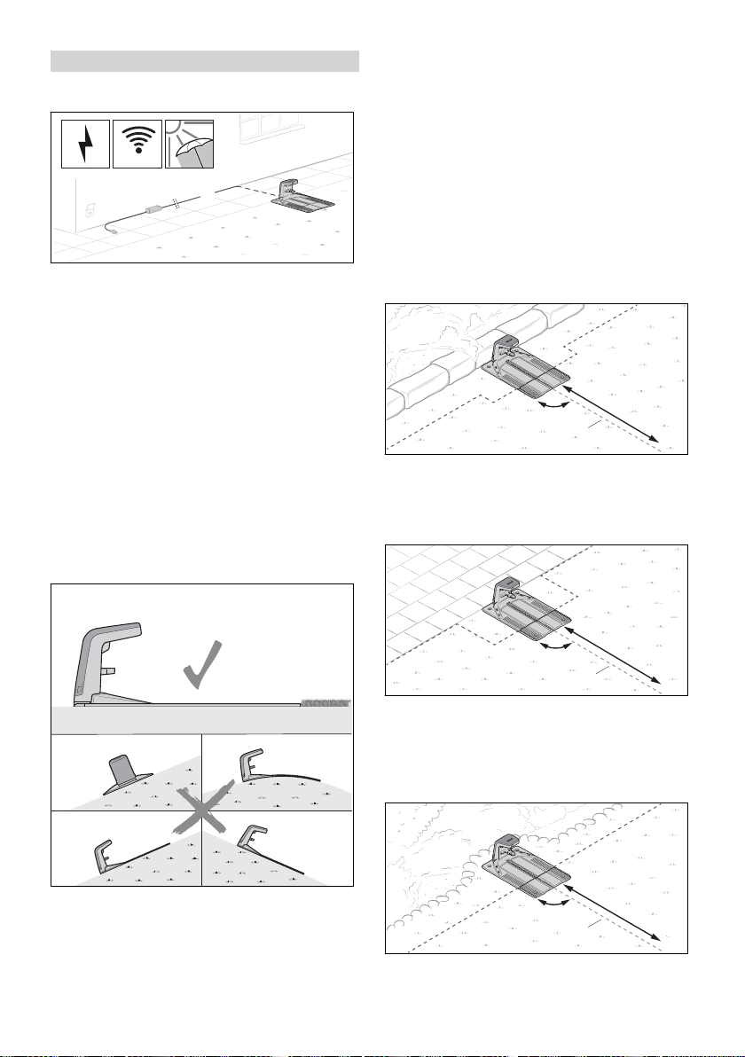
Die Dockingstation steht am Rand der Mähflä‐
che. Die angrenzende Fläche ist befahrbar und
der Leitdraht (1) kann auf einer Länge a = 2 m
gerade von der Dockingstation in die Mähfläche
geführt werden.
► Dockingstation so ausrichten, dass folgende
Bedingungen erfüllt sind:
Die Dockingstation steht auf einer ebenen
–
Fläche.
Die Dockingstation zeigt mit ihrer Öffnung
–
nach vorne in Richtung der Mähfläche.
0458-012-9601-A 17
Die Dockingstation steht teilweise in einem Beet
und teilweise auf der Mähfläche und der Leit‐
Page 18

a
90°
1
0000099845_001
a
a
b
1
0000099846_001
b
a
a
c
c
1
1
0000099847_001
deutsch 7 Dockingstation aufstellen
draht (1) kann auf einer Länge a = 2 m gerade
von der Dockingstation in die Mähfläche geführt
Dockingstation mitten auf der Mähfläche aufstel‐
len
werden.
Die Dockingstation steht teilweise auf einer
befahrbaren Fläche und teilweise auf der Mähflä‐
che und der Leitdraht (1) kann auf einer Länge a
= 2 m gerade von der Dockingstation in die Mäh‐
fläche geführt werden.
►
Dockingstation vorbereiten, 7.3.
► Dockingstation auf der Mähfläche aufstellen,
7.4.
Dockingstation außerhalb der Mähfläche aufstel‐
len
Die Dockingstation wird als „Insel“ mitten auf der
Mähfläche positioniert.
Bei dieser Variante wird der Begrenzungsdraht
um die Dockingstation herum nach hinten an den
Rand der Mähfläche geführt. Der Leitdraht wird
nach vorne zum Rand der Mähfläche geführt.
Der seitliche Abstand zu angrenzenden Flächen
muss mindestens a = 37 cm (Länge: 1x iMOW
®
Ruler) betragen.
Der Abstand der hinteren Kante der Dockingsta‐
tion zum Rand der Mähfläche muss einen
Die Dockingstation steht außerhalb der Mähflä‐
che.
Der seitliche Abstand zu angrenzenden Flächen
muss mindestens a = 15 cm betragen.
Der Abstand der vorderen Kante der Dockingsta‐
tion zur Mähfläche muss mindestens b = 2 m
Abstand von mindestens b = 2 m betragen.
Der Leitdraht (1) muss auf einer Länge a = 2 m
gerade von der Dockingstation in die Mähfläche
geführt werden können.
►
Dockingstation vorbereiten,
7.3.
► Dockingstation mitten auf der Mähfläche auf‐
stellen, 7.6.
betragen.
Bei dieser Variante muss zum Abschluss der
Inbetriebnahme zwingend ein Startpunkt (1) in
der Mähfläche gesetzt werden. Der Mähroboter
startet dann das Mähen von diesem Punkt aus
und nicht direkt ab der Dockingstation. Start‐
punkte können über die App „MYiMOW®“ einge‐
stellt werden. Die Anfahrtshäufigkeit des Start‐
punkts (1) muss in der App auf 100 % gesetzt
werden.
►
Dockingstation vorbereiten,
► Dockingstation außerhalb der Mähfläche auf‐
stellen, 7.5.
18 0458-012-9601-A
7.3.
Page 19

0000100046_001
0000100401_001
1
0000099954_001
2
3
0000100292_001
0000100047_001
0000100051_001
A
B B
A
4
6
7 Dockingstation aufstellen deutsch
7.3 Dockingstation vorbereiten
Ladekabel anschließen
HINWEIS
■ Die Steckverbindungen des Ladekabels sind
im montierten Zustand gegen Verschmutzung
z. B. Staub und Schmutz geschützt. Falls die
Steckverbindungen verschmutzt sind kann es
zu Betriebsstörungen der Dockingstation kom‐
men.
►
offene Steckverbindungen vor Verschmut‐
zung schützen.
► Verschmutzte Steckverbindungen so reini‐
gen, wie es in dieser Gebrauchsanleitung
beschrieben ist.
Das Ladekabel kann standardmäßig von hinten
angeschlossen werden.
► Rasthebel (2) drücken und die Abdeckung (3)
aufklappen.
► Falls die Dockingstation von hinten ange‐
schlossen werden soll:
► Stecker (4) in die Durchführung (5) stecken
und das Ladekabel (6) nachführen.
Das Ladekabel (6) wird im Inneren der
Dockingstation nach oben geschoben.
► Falls die Dockingstation direkt an einer Wand
Falls die Dockingstation direkt an einer Wand
steht, kann das Ladekabel auch unter der
Bodenplatte verlegt werden. Das Ladekabel
kann links oder rechts aus der Bodenplatte
heraus verlegt werden.
steht oder das Ladekabel unter der Boden‐
platte zur Seite geführt werden soll:
► Auf der gewünschten Seite der Bodenplatte
an der Position (A) den Rand öffnen und
entgraten.
► In der Mitte der Bodenplatte eine Öff‐
nung (B) ausschneiden und entgraten.
► Stecker (4) in die Öffnung (B) stecken und
das Ladekabel (6) nachführen.
Das Ladekabel (6) wird im Inneren der
Dockingstation nach oben geschoben.
► Haube (1) auf beiden Seiten leicht nach außen
biegen und nach oben abnehmen.
0458-012-9601-A 19
Page 20

6
4
7
0000100049_001
8
0000099826_001
9
10
0000099958_001
37 cm (14.5 in.)
15 cm (6 in.)
27,5 cm (10.75 in.)
a
0000099959_001
9
11
0000100402_001
1
2
0000099960_001
4
1
3
0000100294_001
1
3
0000099961_001
deutsch 7 Dockingstation aufstellen
► Ladekabel (6) im Kabelhalter (7) fixieren.
► Stecker (4) einstecken.
Der Stecker (4) rastet auf beiden Seiten hör‐
bar und spürbar ein.
Dockingstation befestigen
► Dockingstation mit vier Erdnägel (8) am Boden
befestigen.
Begrenzungsdraht einführen
► Drahtanfang (9) in die rechte Durchfüh‐
rung (10) stecken und nachführen.
Der Begrenzungsdraht (9) wird im Inneren der
Dockingstation nach oben geschoben.
► Drahtanfang (9) nahe am Gehäuse mit dem
passenden Kabelmarkierer (11) kennzeich‐
nen.
Die Kennzeichnung erleichtert den späteren
Anschluss an die richtige Klemme.
7.4 Dockingstation auf der Mähflä‐
che aufstellen
► Begrenzungsdraht (1) so in der Bodenplatte
verlegen, dass er flach im Kabelkanal liegt und
von den Haken (2) fixiert ist.
► Begrenzungsdraht (1) direkt an der Boden‐
platte (3) mit einem Fixiernagel (4) befestigen.
Falls die Dockingstation an einer Wand steht:
► Begrenzungsdraht so lange nachführen, bis er
auf einer Länge von a = 37 cm (Länge:
1x iMOW® Ruler) nach oben übersteht.
20 0458-012-9601-A
Page 21

1
3
0000100296_001
1
3
0000099964_001
1
3
0000100397_001
1
2
0000099965_001
1
3
4
0000100295_001
1
a
0000099966_001
7 Dockingstation aufstellen deutsch
► Begrenzungsdraht (1) 37 cm (Länge:
1x iMOW® Ruler) seitlich von der Boden‐
platte (3) wegführen.
► Begrenzungsdraht (1) parallel zur Boden‐
platte (3) zum Rand der Mähfläche führen und
den Abstand zur Wand von 37 cm (Länge:
1x iMOW® Ruler) einhalten.
► Begrenzungsdraht (1) um die Mähfläche im
Uhrzeigersinn verlegen, 8.
Falls die Dockingstation an einer angrenzenden,
befahrbaren Fläche steht:
► Begrenzungsdraht (1) von der Bodenplatte (3)
seitlich wegführen und entlang der befahrba‐
ren Fläche verlegen.
► Begrenzungsdraht (1) um die Mähfläche im
Uhrzeigersinn verlegen, 8.
7.5 Dockingstation außerhalb der Mähfläche aufstellen
► Begrenzungsdraht (1) 37 cm (Länge:
1x iMOW® Ruler) seitlich von der Boden‐
platte (3) wegführen.
► Begrenzungsdraht (1) parallel zur Boden‐
platte (3) zum Rand der Mähfläche führen.
► Begrenzungsdraht (1) um die Mähfläche im
Uhrzeigersinn verlegen, 8.
Falls die Dockingstation teilweise in einem Beet
und teilweise auf der Mähfläche steht:
► Begrenzungsdraht (1) so in der Bodenplatte
verlegen, dass er flach im Kabelkanal liegt und
von den Haken (2) fixiert ist.
► Begrenzungsdraht (1) von der Bodenplatte (3)
platte (3) mit einem Fixiernagel (4) befestigen.
seitlich wegführen und den Abstand von
37 cm (Länge: 1x iMOW® Ruler) parallel zum
Beet einhalten.
► Begrenzungsdraht (1) um die Mähfläche im
Uhrzeigersinn verlegen, 8.
Falls die Dockingstation teilweise auf einer
befahrbaren Fläche und teilweise auf der Mähflä‐
che steht:
► Begrenzungsdraht (1) direkt an der Boden‐
0458-012-9601-A 21
Page 22

1
2
0000099960_001
4
1
3
0000100294_001
1
3
a
0000100048_001
b
c
a
1
2
0000099843_001
deutsch 8 Begrenzungsdraht verlegen
► Begrenzungsdraht (1) nach vorne zur Mähflä‐
che führen.
Der richtige Abstand zum Rand der Mähfläche
ist davon abhängig, ob der Rand der Mähflä‐
che befahrbar ist, oder ein Abstand von
a = 37 cm (Länge: 1x iMOW® Ruler) eingehal‐
ten werden muss.
► Begrenzungsdraht (1) um die Mähfläche im
Uhrzeigersinn verlegen, 8.
7.6 Dockingstation mitten auf der Mähfläche aufstellen
► Begrenzungsdraht (1) so in der Bodenplatte
verlegen, dass er flach im Kabelkanal liegt und
von den Haken (2) fixiert ist.
► Begrenzungsdraht (1) mindestens 37 cm
(Länge: 1x iMOW® Ruler) von der Boden‐
platte (3) seitlich wegführen.
► Begrenzungsdraht (1) im Abstand von mindes‐
tens a = 2 m hinter die Bodenplatte (3) führen.
► Begrenzungsdraht (1) mittig hinter der
Dockingstation zum Rand der Mähfläche füh‐
ren.
Der richtige Abstand zum Rand der Mähfläche
muss abhängig von der angrenzenden Fläche
eingehalten werden.
► Begrenzungsdraht (1) um die Mähfläche im
Uhrzeigersinn verlegen,
8.
8 Begrenzungsdraht verle‐
gen
8.1 Allgemeine Vorgaben
Verlauf von Begrenzungsdraht und Leitdraht in
der Mähfläche prüfen
► Begrenzungsdraht (1) direkt an der Boden‐
platte (3) mit einem Fixiernagel (4) befestigen.
► Sicherstellen, dass entlang des Begren‐
zungsdrahts und des Leitdrahts die Mähfläche
auf folgenden Breiten eben und möglichst frei
von Hindernissen ist:
Begrenzungsdraht (1)
–
nach außen: a = 37 cm (Länge: 1x iMOW
Ruler)
nach innen: b = 1,2 m
–
Leitdraht (2)
rechts in Fahrtrichtung zur Dockingstation:
–
a = 37 cm (Länge: 1x iMOW® Ruler)
links in Fahrtrichtung zur Dockingstation:
–
c = 1,2 m
22 0458-012-9601-A
®
Page 23

a
0000100053_001
a
0000100058_001
4
1
2
3
A
B
0000100239_001
8 Begrenzungsdraht verlegen deutsch
Begrenzungsdraht verlegen
► An der Dockingstation beginnend den Begren‐
zungsdraht im Uhrzeigersinn verlegen.
► Begrenzungsdraht nicht knicken, durchtren‐
nen, spannen oder kreuzen.
► Sicherstellen, dass sich der Begrenzungsdraht
nicht mit einem Leitdraht kreuzt.
► Ausnahme: Bei der Installation einer Gasse
muss der Leitdraht den Begrenzungsdraht
kreuzen.
► Einen Abstand von mindestens 1 m zu
Begrenzungsdrähten benachbarter Mährobo‐
ter-Installationen einhalten.
► Sicherstellen, dass die Länge des Begren‐
zungsdrahts 850 m nicht übersteigt.
Begrenzungsdraht und Leitdraht befestigen
► Begrenzungsdraht über eine Länge a = 1 m
parallel und eng aneinander um 2 Fixiernägel
führen, ohne dass sich die Begrenzungsdrähte
überkreuzen.
► Drahtreserve in der Mitte mit zwei weiteren
Fixiernägeln befestigen.
8.2 Leitdraht einplanen und
Anschlussstelle im Begren‐
zungsdraht verlegen
Die Verlegung des Leitdrahts oder mehrerer Leit‐
drähte muss im Vorfeld sorgfältig geplant wer‐
den. Bereits bei der Verlegung des Begren‐
zungsdrahts muss die Position aller Leitdrähte
berücksichtigt werden. Mindestens ein Leitdraht
muss verlegt werden, drei Leitdrähte können ver‐
► Begrenzungsdraht und Leitdraht mit den
Fixiernägeln so befestigen, dass folgende
Bedingungen erfüllt sind:
Der Abstand zwischen den Fixiernägeln
–
beträgt höchstens a = 1 m.
Der Begrenzungsdraht und Leitdraht liegt
–
an allen Stellen flach auf dem Boden auf.
Die Fixiernägel sind vollständig versenkt.
–
Drahtreserve verlegen
Drahtreserven erleichtern Korrekturen bei der
Drahtverlegung und geben Spielraum für zukünf‐
tige Anpassungen.
Beispiele:
Ein Beet wird erweitert und muss neu abge‐
–
grenzt werden.
Büsche und Sträucher wachsen und der
–
Begrenzungsdraht muss in einem größeren
Bogen um das Gewächs geführt werden.
Der Begrenzungsdraht wurde an der Docking‐
–
station zu kurz abgeschnitten und kann nicht
angeschlossen werden.
Eine oder auch mehrere Drahtreserven können
eingeplant und verlegt werden.
0458-012-9601-A 23
legt werden.
Ein Leitdraht (1) erfüllt folgende Funktionen:
Orientierung für die Heimfahrt zur Dockingsta‐
–
tion (2)
Ansteuern eines Startpunkts (3)
–
Teilt die Mähfläche in Zonen (A und B) ein
–
Der Leitdraht (1) wird an der Dockingstation (2)
beginnend durch die Mähfläche verlegt und an
einer möglichst weit entfernten Stelle an den
umlaufenden Begrenzungsdraht (4) angeschlos‐
10
sen.
Page 24

a
c
b
90°
90°
0000100423_001
0000100417_001
4
d
5
0000100229_001
deutsch 8 Begrenzungsdraht verlegen
► Leitdraht so einplanen, dass folgende Bedin‐
gungen erfüllt sind:
Der Leitdraht wird auf einer Länge a =2 m
–
gerade von der Dockingstation in die Mähflä‐
che geführt.
Der Mindestabstand zwischen Leitdraht und
–
dem umlaufenden Begrenzungsdraht beträgt
b = 27,5 cm
Der Leitdraht wird mit einem Mindestabstand
–
c = 37 cm (Länge: 1x iMOW® Ruler) gerade
und im rechten Winkel an den Begrenzungs‐
draht geführt und angeschlossen.
Bei der Installation des umlaufenden Begren‐
zungsdrahts (4), muss die Anschlussstelle für
den Leitdraht verlegt werden:
► Begrenzungsdraht (4) an den vorgesehenen
Stellen mit einem Fixiernagel (5) befestigen.
► Begrenzungsdraht (4) zu einer Schleife mit
einer Länge d = 15 cm legen und mit einem
weiteren Fixiernagel (5) befestigen.
► Begrenzungsdraht (4) am Ende der Draht‐
schleife z. B. mit einem Seitenschneider
durchtrennen.
Die Drahtenden werden zum Abschluss der
Der Leitdraht darf sich nicht mit einer Sperrflä‐
–
chenverbindung kreuzen.
Der Leitdraht darf nicht in einer Ecke an den
–
Begrenzungsdraht angeschlossen werden.
Der Leitdraht darf sich nicht mit einem Begren‐
–
zungsdraht überkreuzen.
Ausnahme: Bei der Installation einer Gasse
muss der Leitdraht den Begrenzungsdraht
kreuzen.
Der Leitdraht darf nicht geknickt oder
–
gespannt sein und er darf sich nicht selbst
überkreuzen.
Installation mit dem Leitdraht verbunden.
10
► Begrenzungsdraht (4) weiter um die Mähflä‐
che verlegen.
8.3 Ecken
Ecken mit einem Winkel von 90°
Ecken mit einem Winkel von 90° können in zwei
Ecken mit einem Winkel von 45° unterteilt wer‐
den. Der Mähroboter ändert seine Richtung in
diesem Bereich dadurch gleichmäßiger und
weniger ruckartig.
24 0458-012-9601-A
Page 25

0000100400_001
> 90°
< 90°
< 90°
> 90°
0000100054_001
< a
0000100057_001
8 Begrenzungsdraht verlegen deutsch
► Begrenzungsdraht in der Ecke auf einer Länge
von mindestens 37 cm (Länge: 1x iMOW
®
Ruler) quer verlegen.
Spitz zulaufende Ecken mit einem Winkel < 90°
Spitz zulaufende Ecken mit einem Winkel < 90°
in zwei Ecken unterteilen. Der Mähroboter ändert
dadurch seine Richtung in diesem Bereich
gleichmäßiger und weniger ruckartig.
37 cm (Länge: 1x iMOW
®
Ruler) geradeaus
verlegen.
► Dann eine Ecke mit einem Winkel von grö‐
ßer als 90° verlegen. Danach den Begren‐
zungsdraht auf einer Länge von mindestens
37 cm (Länge: 1x iMOW® Ruler) gerade
verlegen.
8.4 Befahrbare Fläche
Direkt an die Mähfläche angrenzende Flächen
können vom Mähroboter befahren werden, wenn
der Höhenunterschied zwischen der befahrbaren
Fläche und der Mähfläche nicht mehr als 1,5 cm
beträgt. Der Untergrund muss fest und frei von
Hindernissen sein.
Beispiele:
Terrasse
–
Gepflasterter Weg
–
Rasenkantensteine oder Platten
–
Durch einen geringen Abstand des Begren‐
zungsdrahts zur befahrbaren Fläche wird randlo‐
ses Mähen ermöglicht.
► Begrenzungsdraht ohne Abstand parallel zur
befahrbaren Fläche verlegen.
Der maximale Höhenunterschied zwischen der
befahrbaren Fläche und der Mähfläche beträgt
a = 1,5 cm
8.5 Nicht befahrbare Fläche
Eine Fläche ist nicht befahrbar, wenn Hinder‐
nisse in Bodennähe in die Mähfläche ragen, der
► Sicherstellen, dass bei spitz zulaufenden
Ecken ein Winkel von 90° nicht unterschritten
wird.
► Falls der Winkel von 90° unterschritten wird:
Winkel unterteilen.
► Eine Ecke mit einem Winkel von größer als
90° verlegen. Danach den Begrenzungs‐
draht auf einer Länge von mindestens
0458-012-9601-A 25
Untergrund nicht fest ist oder sehr uneben ist
und wenn der Höhenunterschied zwischen der
Mähfläche und der angrenzenden Fläche mehr
als 1,5 cm beträgt.
Beispiele:
Mauer oder Zaun
–
Hecke oder Büsche mit tief wachsenden Zwei‐
–
gen
Steingarten oder geschotterter Weg
–
Stark verwurzelter oder unebener Boden
–
Page 26

0000099948_001
a
0000100062_001
a
0000100063_001
1
b
a
a
a
1
0000100055_001
deutsch 8 Begrenzungsdraht verlegen
► Begrenzungsdraht in einem Abstand von
37 cm (Länge: 1x iMOW® Ruler) parallel zur
nicht befahrbaren Fläche verlegen.
► Falls sich die nicht befahrbare Fläche auf der
Mähfläche befindet: Nicht befahrbare Fläche
mit einer Sperrfläche abgrenzen.
8.6 Wasserfläche
Zu Wasserflächen muss ein erhöhter Drahtab‐
stand eingehalten werden, wenn die Wasserflä‐
che nicht durch ein festes und mindestens 10 cm
hohes Hindernis von der Mähfläche abgegrenzt
ist.
Beispiele:
Gartenteich
–
Pool
–
Bach oder Wasserlauf
–
► Begrenzungsdraht in einem Abstand von
a = 1 m parallel zur Absturzkante verlegen.
8.8 Sperrfläche
Bereiche auf der Mähfläche, die nicht vom Mäh‐
roboter befahren werden können oder dürfen,
müssen über eine Sperrfläche abgegrenzt wer‐
den.
Beispiele:
Beet ohne eine feste und mindestens 10 cm
–
hohe Umrandung
Gartenteich oder Pool ohne eine feste und
–
mindestens 10 cm hohe Umrandung
Hindernisse, die nicht berührt werden dürfen
–
Hindernisse, die nicht ausreichend fest sind
–
Hindernisse, die niedriger als 10 cm sind
–
Für einen robusten Mähbetrieb sollten Sperrflä‐
chen keine nach innen gewölbte Formen aufwei‐
sen.
► Begrenzungsdraht in einem Abstand von
a = 1 m parallel zum Uferbereich verlegen.
► Falls sich die Wasserfläche auf der Mähfläche
befindet: Wasserfläche mit einer Sperrfläche
abgrenzen.
8.7 Absturzkante
Zu Absturzkanten muss ein erhöhter Drahtab‐
stand eingehalten werden, wenn die Absturz‐
kante nicht durch ein festes und mindestens
10 cm hohes Hindernis von der Mähfläche abge‐
grenzt ist.
Beispiele:
Treppe
–
Stützmauer
–
abgestufter Hang
–
26 0458-012-9601-A
Page 27

1
0000100232_001
a
0000100064_001
a
b
b
1
1
0000100065_001
2
2
3
b
b
1
1
1
1
a
0000100418_001
8 Begrenzungsdraht verlegen deutsch
► Begrenzungsdraht (1) vom Rand weg in Rich‐
8.10 Engstelle
tung Sperrfläche führen. Sicherstellen, dass
für die Sperrfläche folgende Maße eingehalten
sind:
Mindestabstand zu anderen Begrenzungsd‐
–
rähten a = 55 cm
–
Drahtabstand b = 37 cm (Länge: 1x iMOW
®
Ruler) (bei Wasserflächen und Absturzkan‐
ten b = 1 m)
minimaler Durchmesser der Sperrfläche
–
74 cm
Der Mähroboter befährt alle Engstellen, solange
ein Mindestabstand (a) zwischen den Begren‐
zungsdrähten (1) eingehalten wird.
► Begrenzungsdraht (1) wie abgebildet verlegen
und sicherstellen, dass folgende Maße einge‐
halten sind:
Mindestabstand zwischen den Begrenzungsd‐
–
rähten (1) in der Engstelle: a = 2 m
Falls die Engstelle durch seitliche Hindernisse
–
eingegrenzt wird: Zusätzlich einen Abstand
von b = 37 cm (Länge: 1x iMOW® Ruler)
berücksichtigen
► Falls der Mindestabstand a = 2 m zwischen
den Begrenzungsdrähten (1) unterschritten
wird:
Einen Leitdraht mittig durch die Engstelle ver‐
legen.
Engstelle mit Leitdraht
► Begrenzungsdraht (1) um den abzugrenzen‐
den Bereich verlegen.
► Begrenzungsdraht (1) parallel und eng neben‐
einander zurück zum Rand führen, ohne dass
sich die Begrenzungsdrähte überkreuzen.
8.9 Festes Hindernis
Ein festes Hindernis auf der Mähfläche muss
nicht durch eine Sperrfläche abgegrenzt werden,
wenn das Hindernis mindestens 10 cm hoch ist.
Das Hindernis wird durch die Ultraschallsenso‐
ren und den Stoßsensor erkannt.
Ein Leitdraht (2) führt den Mähroboter gezielt
durch eine Engstelle, solange ein Mindestab‐
► Ein festes Hindernis mit einer Höhe von min‐
destens a = 10 cm muss nicht abgegrenzt
werden.
0458-012-9601-A 27
stand (a) zwischen den Begrenzungsdrähten (1)
eingehalten wird.
Zum Abschluss der Inbetriebnahme muss ein
Startpunkt (3) hinter der Engstelle und dessen
Page 28

A
B
1
2
3
a
b
b
0000100418_0010000100066_001
5
4
L L
R R
L
L
R
R
0000099970_001
d d
a
b
b
c
4
0000100067_001
deutsch 8 Begrenzungsdraht verlegen
Anfahrtshäufigkeit gesetzt werden. Andernfalls
findet der Mähroboter nicht durch die Engstelle.
Startpunkte können über die App „MYiMOW®“
eingestellt werden.
► Begrenzungsdraht (1) wie abgebildet verlegen
und sicherstellen, dass folgende Maße einge‐
halten sind:
Mindestabstand zwischen den Begrenzungsd‐
–
rähten (1) in der Engstelle: a = 55 cm
Falls die Engstelle durch seitliche Hindernisse
–
eingrenzt wird: Zusätzlich einen Abstand von
b = 37 cm (Länge: 1x iMOW® Ruler) berück‐
sichtigen
► Leitdraht (2) in der Mitte der Engstelle verle‐
gen.
► Falls der seitliche Abstand b = 37 cm (Länge:
1x iMOW® Ruler) unterschritten wird: Eine
Gasse installieren, um den Mähroboter zu
einer weiteren Mähfläche leiten zu können
8.11 oder den Bereich der Engstelle von der
Mähfläche abgrenzen.
8.11 Gasse
► Falls die Engstelle durch seitliche Hindernisse
eingrenzt wird: Zusätzlich einen Mindestab‐
stand von b = 15 cm berücksichtigen
Zum Abschluss der Inbetriebnahme muss ein
Startpunkt (3) hinter der Gasse (1) und dessen
Anfahrtshäufigkeit gesetzt werden. Andernfalls
findet der Mähroboter nicht von der Hauptmäh‐
fläche (A) durch die Gasse (1) zum weiteren
Mähbereich (B). Startpunkte können über die
App „MYiMOW®“ eingestellt werden.
► Falls die Mindestbreite zwischen den Begren‐
zungsdrähten nicht eingehalten werden kann:
Weiteren Mähbereich (B) von der Hauptmäh‐
fläche (A) abgrenzen und eine Nebenfläche
installieren.
8.13
► Begrenzungsdraht (4) wie abgebildet verlegen
und sicherstellen, dass die richtige Position
der Drahtschlaufen (5) eingehalten wird:
Die Drahtschlaufen (5) müssen in Fahrtrich‐
–
tung zur Dockingstation links = (L) verlegt
werden.
Der Abschnitt an dem die Begrenzungsd‐
–
rähte (4) eng und parallel zueinander liegen
Mit Hilfe einer Gasse (1) können Engstellen ziel‐
gerichtet überwunden, oder Überfahrten definiert
werden.
Eine Gasse (1) verbindet die Hauptmähflä‐
–
che (A) mit einem weiteren Mähbereich (B).
In einer Gasse (1) muss ein Leitdraht (2) ver‐
–
befindet sich in Fahrtrichtung zur Docking‐
station rechts = (R).
legt werden.
Innerhalb einer Gasse (1) wird nicht gemäht.
–
Eine Gasse muss eine Mindestbreite zwischen
–
den Begrenzungsdrähten von a = 55 cm
haben.
28 0458-012-9601-A
Page 29

f
90° 90°
e
0000099969_001
0000100399_001
a
a
b
c
0000100068_001
8 Begrenzungsdraht verlegen deutsch
► Begrenzungsdraht (4) wie abgebildet verlegen
und sicherstellen, dass folgende Maße einge‐
halten sind:
Breite zwischen den Begrenzungsdrähten in
–
der Gasse: a = 55 cm
Mindestabstand zu seitlichen Hindernissen:
–
b = 15 cm
Minimale Länge der Gasse: c = 74 cm
–
(2x iMOW® Ruler)
Abstand der Begrenzungsdrähte der Draht‐
–
schlaufe: d = 37 cm (Länge: 1x iMOW
Ruler)
®
► Falls sich eine Steigung / Gefälle bis 27 %
innerhalb der Mähfläche befindet: Begren‐
zungsdraht normal verlegen.
► Beim Verlegen des Leitdrahts (2) sicherstel‐
len, dass folgende Maße und Abstände einge‐
halten sind:
Der Leitdraht (2) wird mittig in der Gasse
–
verlegt.
Leitdraht (2) vor der Gasse auf einer Länge
–
von mindestens e = 37 cm (Länge: 1x
iMOW® Ruler) gerade und im rechten Win‐
kel (90°) zur Gasse führen.
Leitdraht (2) nach der Gasse auf einer
–
Länge von mindestens f = 2 m gerade und
im rechten Winkel (90°) von der Gasse weg‐
führen.
8.12 Steigungen / Gefälle
Der Mähroboter kann Steigungen bis zu 45 %
befahren und mähen. Mit dem Upgrade Kit 10,
iMOW® Traktionsräder können Steigungen bis
zu 60 % befahren und gemäht werden. Das
► Falls sich eine Steigung / Gefälle von mehr als
27 % innerhalb der Mähfläche befindet: Vor
und nach der Steigung / dem Gefälle den
Begrenzungsdraht mit einem Abstand a = min‐
destens 1,20 m verlegen.
► Damit der Mähroboter den Übergang zwi‐
schen Ebene und Steigung / Gefälle befahren
kann, muss der Radius des Übergangs so
beschaffen sein, dass auf einer Länge b = 1 m
der Abstand zum Boden c = 10 cm nicht über‐
schritten wird.
8.13 Nebenfläche
Eine Nebenfläche kann vom Mähroboter nicht
selbst angefahren werden. Der Mähroboter muss
durch den Kunden in der Nebenfläche platziert
werden.
In einer Nebenfläche darf kein Leitdraht verlegt
sein.
Upgrade Kit 10 ist als Zubehör erhältlich.
0458-012-9601-A 29
Page 30

A
B
a
0000099951_001
3
1
2
0000100243_001
1
4
0000100404_001
1
5
0000100245_001
1
6
0000100246_001
2
1
0000100249_001
deutsch 9 Verlegung des Begrenzungsdrahts abschließen
► Begrenzungsdraht (1) von der Hauptfläche (A)
in die Nebenfläche (B) führen und verlegen.
Mindestabstand zu den Begrenzungsdrähten
a = 74 cm
► Sicherstellen, dass die Länge des Begren‐
zungsdrahts (1) 850 m nicht übersteigt.
► Begrenzungsdraht (1) parallel und eng anei‐
nander zurück zur Mähfläche (A) führen, ohne
dass sich die Begrenzungsdrähte überkreu‐
zen.
8.14 Kleine Mähfläche
Bei einer kleinen Mähfläche, bei der weniger als
20 m Begrenzungsdraht benötigt wird, muss das
Kleinflächenmodul STIHL AKM 100 verwendet
werden.
Das STIHL AKM 100 stabilisiert das Drahtsignal
und wird mit Hilfe von Drahtverbindern in den
Begrenzungsdraht eingebunden.
9 Verlegung des Begren‐
zungsdrahts abschließen
9.1 Verlegung des Begrenzungsd‐
rahts abschließen
Dockingstation auf dem Rand der Mähfläche,
Dockingstation am Rand der Rasenfläche
► Begrenzungsdraht (1) so in der Bodenplatte
verlegen, dass er flach im Kabelkanal liegt und
von den Haken (4) fixiert ist.
► Begrenzungsdraht (1) in die linke Durchfüh‐
rung (5) stecken und nachführen.
Das Drahtende (1) wird im Inneren der Docking‐
station nach oben geschoben.
► Drahtende (1) nahe am Gehäuse mit dem
passenden Kabelmarkierer (6) kennzeichnen.
Dockingstation außerhalb der Mähfläche
► Begrenzungsdraht (1) direkt an der Boden‐
platte (2) mit einem Fixiernagel (3) befestigen.
► Mit dem Begrenzungsdraht (1) zwei Breiten
der Bodenplatte (2) abmessen und Begren‐
zungsdraht (1) danach mit einem Seiten‐
schneider ablängen.
30 0458-012-9601-A
► Begrenzungsdraht (1) eng an bereits verlegten
Begrenzungsdraht führen und mit einem
Fixiernagel (2) befestigen.
Page 31

3
1
0000100251_001
4
1
3
0000100244_001
1
5
0000100415_001
1
6
0000100424_001
1
7
0000100416_001
1
3
0000100252_001
9 Verlegung des Begrenzungsdrahts abschließen deutsch
► Begrenzungsdraht (1) in die linke Durchfüh‐
rung (6) stecken und nachführen.
Das Drahtende (1) wird im Inneren der Docking‐
station nach oben geschoben.
► Begrenzungsdraht (1) eng und parallel zum
anderen Begrenzungsdraht auf einer Länge
von 37 cm (Länge: 1x iMOW® Ruler) zurück
zur Dockingstation führen, ohne dass sich die
Begrenzungsdrähte überkreuzen.
► Begrenzungsdraht (1) zurück zum Rand und
weiter zur Bodenplatte (3) führen.
► Drahtende (1) nahe am Gehäuse mit dem
passenden Kabelmarkierer (7) kennzeichnen.
Zum Abschluss der Inbetriebnahme muss zwin‐
gend ein Startpunkt in der Mähfläche gesetzt
werden. Andernfalls findet der Mähroboter nicht
zur Mähfläche. Startpunkte und deren Anfahrts‐
häufigkeit können über die App „MYiMOW®“ ein‐
gestellt werden.
Dockingstation mitten auf der Mähfläche aufstel‐
len
► Begrenzungsdraht (1) direkt an der Boden‐
platte (3) mit einem Fixiernagel (4) befestigen.
► Mit dem Begrenzungsdraht (1) zwei Breiten
der Bodenplatte (3) abmessen und Begren‐
zungsdraht (1) danach mit einem Seiten‐
schneider ablängen.
► Begrenzungsdraht (1) so in der Bodenplatte
verlegen, dass er flach im Kabelkanal liegt und
von den Haken (5) fixiert ist.
► Begrenzungsdraht (1) eng an den bereits ver‐
legten Begrenzungsdraht führen.
► Begrenzungsdraht (1) eng und parallel zum
anderen Begrenzungsdraht zurück zur
Dockingstation führen, ohne dass sich die
Begrenzungsdrähte überkreuzen.
► Begrenzungsdraht (1) im Abstand von 37 cm
0458-012-9601-A 31
(Länge: 1x iMOW® Ruler) um die Boden‐
platte (3) nach vorne führen.
Page 32

3
1
2
0000100243_001
1
4
0000100404_001
1
5
0000100245_001
1
6
0000100246_001
1
2
0000100235_001
37 cm (14.5 in.)
15 cm (6 in.)
27,5 cm (10.75 in.)
a
0000100236_001
1
3
0000100405_0010000100405_001
deutsch 10 Leitdraht verlegen
10 Leitdraht verlegen
10.1 Leitdraht verlegen
Bereits bei der Verlegung des Begrenzungsd‐
rahts muss die Position aller Leitdrähte berück‐
sichtigt werden.
► Allgemeine Vorgaben zur Verlegung des Leit‐
drahts berücksichtigen
► Begrenzungsdraht (1) direkt an der Boden‐
platte (2) mit einem Fixiernagel (3) befestigen.
► Mit dem Begrenzungsdraht (1) zwei Breiten
der Bodenplatte (2) abmessen und Begren‐
zungsdraht (1) danach mit einem Seiten‐
schneider ablängen.
► Anfang des Leitdrahts (1) in die mittlere
Durchführung (2) stecken und nachführen.
Der Leitdraht (1) wird im Inneren der Docking‐
station nach oben geschoben.
► Begrenzungsdraht (1) so in der Bodenplatte
verlegen, dass er flach im Kabelkanal liegt und
von den Haken (4) fixiert ist.
8.1.
► Leitdraht (1) so lange nachführen, bis er auf
einer Länge von a = 37 cm (Länge: 1x iMOW
Ruler) nach oben übersteht.
► Begrenzungsdraht (1) in die linke Durchfüh‐
rung (5) stecken und nachführen.
Das Drahtende (1) wird im Inneren der Docking‐
station nach oben geschoben.
► Leitdraht (1) nahe am Gehäuse mit dem pas‐
senden Kabelmarkierer (3) kennzeichnen.
Die Kennzeichnung erleichtert den späteren
Anschluss an die richtige Klemme.
► Drahtende (1) nahe am Gehäuse mit dem
passenden Kabelmarkierer (6) kennzeichnen.
32 0458-012-9601-A
®
Page 33

1
4
0000100238_001
6
5
1
0000100406_001
b
7
c
90°
8
1
0000100237_001
c
c
0000100069_001
90°
1
7
0000100230_001
9
1
8
0000100233_001
8
8
1
0000100231_001
10 Leitdraht verlegen deutsch
► Leitdraht (1) so in der Bodenplatte verlegen,
dass er flach im Kabelkanal liegt und von den
Haken (4) fixiert ist.
► Leitdraht (1) direkt an der Bodenplatte (5) mit
einem Fixiernagel (6) befestigen.
► Leitdraht (1) auf einer Länge b = 2 m gerade
und im rechten Winkel (90°) von der Docking‐
station in die Mähfläche führen.
► Leitdraht (1) zur Drahtschleife (7) am Rand
der Mähfläche führen. Der Abstand zum
umlaufenden Begrenzungsdraht (8) muss min‐
destens c = 27,5 cm betragen.
► Leitdraht (1) auf einer Länge von mindestens
37 cm (Länge: 1x iMOW® Ruler) gerade und
im rechten Winkel (90°) zur Drahtschleife (7)
führen.
► Leitdraht (1) durch die Mitte der Draht‐
schleife (7) verlegen.
► Leitdraht (1) am Ende der Drahtschleife (7) mit
einem Seitenschneider durchtrennen und alle
Drahtenden auf die gleiche Länge bringen.
► Enden der Begrenzungsdrähte (8) und des
Leitdrahts (1) bis zum Anschlag in den Draht‐
verbinder (9) stecken.
Die Drahtenden dürfen nicht abisoliert werden.
► Drahtverbinder (1) mit einer Zange bis zum
Anschlag zusammendrücken.
► Begrenzungsdrähte (8) und Leitdraht (1) paral‐
lel und eng aneinander führen, ohne dass sich
die Drähte überkreuzen.
► Drähte mit weiteren Fixiernägeln befestigen.
► An Hängen den Leitdraht diagonal verlegen.
Der Abstand zum Begrenzungsdraht muss
mindestens c = 27,5 cm betragen.
0458-012-9601-A 33
Page 34

2
1
0000100247_001
a
0000100248_001
R
L
1
3
0000100250_001
4
0000100253_001
5
0000100293_001
1
1
2
3
0000099971_001
deutsch 11 Dockingstation elektrisch anschließen
11 Dockingstation elektrisch
anschließen
11.1 Begrenzungsdraht und Leit‐
draht anschließen
► Abdeckung (4) nach vorne klappen.
Die Abdeckung (4) rastet hörbar und spürbar
ein.
► Drahtenden (1) leicht spannen und entlang der
Kante (2) mit einem Seitenschneider ablän‐
gen.
► Haube (5) aufsetzen.
Die Haube (5) rastet hörbar ein.
11.2 Ladekabel verlegen und Netz‐
teil anschließen
► Drahtenden auf einer Länge von a = 10 mm
abisolieren.
► Drahtlitzen so verdrillen, dass keine einzelnen
Drahtlitzen abstehen.
► Ladekabel (1) zum Standort des Netzteils (2)
verlegen.
► Standort für das Netzteil (2) so wählen, dass
folgende Bedingungen erfüllt sind:
Das Netzteil (2) und die Anschlussleitung
► Die beschrifteten Drahtenden den jeweiligen
Klemmen zuordnen.
► Hebel der entsprechenden Klemme (3) nach
hinten aufklappen.
► Das abisolierte Drahtende in die entspre‐
chende Klemme (3) einführen und zum Schlie‐
ßen den Hebel wieder nach vorne klappen.
► Begrenzungsdrähte und Leitdraht wie abgebil‐
det in den Kabelhaltern fixieren und zur rech‐
ten Seite drücken.
34 0458-012-9601-A
–
befinden sich außerhalb der Mähfläche.
Eine geeignete Steckdose befindet sich in
–
Reichweite des Netzteils (2).
Das Netzteil (2) steht auf einer ebenen Flä‐
–
che.
Das Netzteil (2) steht nicht auf einem dauer‐
–
haft nassen Untergrund.
Falls möglich: Der Standort ist vor Witte‐
–
rungseinflüssen geschützt und beschattet.
Page 35

5
4
0000100254_001
a
0000100290_001
0000100255_001
2
1
0000100425_001
12 Mähroboter laden deutsch
Das Netzteil ist waagrecht.
► Ladekabel so verlegen, dass folgende Bedin‐
gungen erfüllt sind:
Das Ladekabel (1) befindet sich außerhalb
–
der Mähfläche.
Das Ladekabel (1) ist so verlegt, dass Per‐
–
sonen nicht darüber stolpern können.
Das Ladekabel (1) ist nicht gespannt oder
–
verwickelt.
Das Ladekabel (1) ist komplett abgewickelt
–
und liegt nicht unter der Dockingstation.
Das Ladekabel (1) liegt nicht auf einem dau‐
–
erhaft nassen Untergrund.
► Ladekabel (1) mit dem Stecker (3) des Netz‐
–
Folgende Abstände sind eingehalten:
Das Netzteil befindet sich außerhalb des
–
Bereichs (a) möglicher Elektroinstallatio‐
nen.
Eine geeignete Steckdose befindet sich in
–
Reichweite des Netzteils.
Falls möglich: Der Standort ist vor Witte‐
–
rungseinflüssen geschützt und beschattet.
12 Mähroboter laden
12.1 Mähroboter laden
teils (2) verbinden.
► Mähroboter bis zum Anschlag in die Docking‐
station schieben.
Der Mähroboter führt einen Systemstart durch
und wird geladen.
Die Ladezeit hängt von verschiedenen Einflüs‐
sen ab, z. B. von der Temperatur des Akkus oder
von der Umgebungstemperatur. Für eine opti‐
male Leistungsfähigkeit die empfohlenen Tem‐
peraturbereiche beachten,
23.7.
► Netzstecker (4) in eine richtig installierte
Steckdose (5) stecken.
Die LED an der Dockingstation leuchtet grün.
11.3 Netzteil an eine Wand montie‐
ren
Das Netzteil kann an eine Wand montiert wer‐
den.
► Netzteil so montieren, dass folgende Bedin‐
gungen erfüllt sind:
Geeignetes Befestigungsmaterial wird ver‐
–
wendet.
0458-012-9601-A 35
Die LED (1) an der Dockingstation leuchtet weiß.
Am Leuchtstreifen des Mähroboters leuchtet eine
LED (2) weiß.
Page 36

3
5
4
0000100426_001
0000099841_001
2
1
3
deutsch 13 Bluetooth®-Funkschnittstelle schließen
►
Energieeffizientes Laden
Um den Akku des Mähroboters mit möglichst
geringen Energiebedarf aufzuladen, können
neben der Ladefunktion alle nicht notwendigen
Zusatzfunktionen des Mähroboters und der
Dockingstation deaktiviert werden.
App „MYiMOW®“ im App Store des mobilen
Endgeräts herunterladen und Account erstel‐
len.
► Mähroboter dem Account hinzufügen.
► Anweisungen auf dem Bildschirm folgen und
die Bluetooth®-Funkschnittstelle mit einem
Passwort sichern.
Nach Vergabe des Passworts ist das mobile
Endgerät zur Steuerung und Konfiguration des
Mähroboters autorisiert.
Ein weiteres mobiles Endgerät kann nur durch
Eingabe des gewählten Passworts autorisiert
werden. Der Mähroboter ist auf diese Weise
gegen unbefugten Zugriff gesichert.
14 Leuchtmuster am Mähro‐
► Falls die Funktion „Diebstahlschutz“ in der App
„MYiMOW®“ aktiviert ist: „Diebstahlschutz“
deaktivieren.
Folgende Tastenkombination nacheinander drü‐
cken:
► „STOP“ (3) drücken.
Der Mähroboter wird gestoppt und gesperrt
► „STOP“ (3) drücken und so lange gedrückt
halten, bis der Leuchtstreifen (4) vollständig
rot leuchtet.
► „STOP“ (1) drücken.
Der Leuchtstreifen (4) blinkt zwei Mal. Die
Gerätesperre des Mähroboters ist aktiviert.
► „STOP“ (3) drücken und so lange gedrückt
halten, bis der Leuchtstreifen (4) vollständig
rot leuchtet und zum Abschluss zweimal rot
blinkt.
Der Modus „energieeffizientes Laden“ ist akti‐
viert. Der Akku des Mähroboter wird voll auf‐
geladen. Alle Zusatzfunktionen sind deakti‐
viert.
Nach dem Ladevorgang muss der Mähroboter
aktiviert werden, damit der Mähroboter wieder
betriebsbereit ist:
► Taste „START“ (5) drücken.
Der Mähroboter ist betriebsbereit.
13 Bluetooth®-Funkschnitt‐
stelle schließen
13.1
Der Mähroboter sendet regelmäßig ein Blue‐
tooth®-Signal aus, um sich mit einem mobilen
Endgerät verbinden zu können. Die Funkschnitt‐
stelle ist im Auslieferungszustand nicht passwort‐
geschützt.
36 0458-012-9601-A
Bluetooth®-Funkschnittstelle einrichten
boter und Dockingstation
14.1 Leuchtstreifen am Mähroboter
Das Matrixdisplay (1) und die Leuchtstreifen (2
und 3) zeigen den Status des Mähroboters
und Störungen an.
Weißes Leuchtmuster:
Kein aktiver Mähvorgang.
–
Grünes Leuchtmuster:
Ein Mähvorgang ist aktiv.
–
Blaues Leuchtmuster:
Der Mähroboter erhält ein Systemupdate
–
oder das System startet neu.
Rotes Leuchtmuster:
Gerätesperre ist aktiv.
–
Störungsmeldung.
–
Page 37

1
0000100257_001
1
2
3
4
5
0000099962_001
15 Mähroboter bedienen und einstellen deutsch
14.2 LED an der Dockingstation
Die LED (1) zeigt den Status der Dockingsta‐
tion und Störungen an.
LED (1) leuchtet weiß:
Die Dockingstation ist betriebsbereit.
–
Der Mähroboter steht in der Dockingstation
–
ohne aktiven Mähvorgang.
Der Mähroboter wird geladen ohne aktiven
–
Mähvorgang.
LED (1) leuchtet grün:
Der Mähroboter wird während eines Mäh‐
–
vorgangs zwischengeladen.
LED (1) leuchtet rot:
Es besteht eine Störung.
–
LED (1) leuchtet blau:
Kommunikation mit dem Mähroboter.
–
15 Mähroboter bedienen und
einstellen
15.1 Bedienfeld
Der Mähroboter und das Mähwerk stoppt. Der
Mähroboter wird gesperrt.
Mähroboter zur Dockingstation senden
► „HAUS“ (4) drücken.
Der Mähroboter fährt zurück zur Dockingsta‐
tion.
Mähroboter entsperren
► „SCHLOSS“ (2) drücken.
► Angezeigte Tastenkombination drücken.
Informationen abrufen
► „INFO“ (5) drücken.
Der Mähroboter gibt akustische Informationen
zum aktuellen Status wieder.
15.2
Um den Mähroboter komfortabel nutzen zu kön‐
nen, ist die Verwendung der App „MYiMOW®“
erforderlich. Über die App „MYiMOW®“ kann der
Mähroboter bedient und eingestellt werden. Der
Mähroboter kann über eine kabellose Netzwerk‐
verbindung (WLAN) und Mobilfunkverbindung
oder per Bluetooth® mit einem mobilen Endgerät
verbunden werden. Von einem Desktop-Compu‐
ter kann der Mähroboter über die Web-App „MYi‐
MOW®“ bedient und eingestellt werden.
Funktionsumfang (Liste nicht vollständig):
–
–
–
–
–
–
App „MYiMOW®“
Mähvorgang starten und stoppen
Mähplan
Mähzeiten einstellen (über einen Assisten‐
–
ten oder manuell)
Startpunkte setzen (optional)
–
Zonen auswählen (optional)
–
Schnitthöhe einstellen
Fernzugriff auf den Mähroboter über eine
kabellose Netzwerkverbindung (WLAN)
Fernzugriff auf den Mähroboter über eine
Mobilfunkverbindung.
Hilfestellung
Über die Drucktasten (1 bis 5) kann der Mähro‐
boter in seinen Grundfunktionen bedient werden.
Der volle Funktionsumfang ist über die App „MYi‐
MOW®“ verfügbar.
Mähvorgang starten
► „START“ (3) drücken.
Der Mähroboter startet den Mähvorgang und
kehrt anschließend automatisch zur Docking‐
station zurück.
Mähvorgang stoppen und Mähroboter sperren
► „STOP“ (1) drücken.
0458-012-9601-A 37
16 Mähroboter stoppen und
Gerätesperre aktivieren
16.1 Mähroboter stoppen und Gerä‐
tesperre aktivieren
Page 38

1
2
0000100291_001
21
0000099953_001
deutsch 17 Transportieren
WARNUNG
■ Falls der Mähroboter nicht wie in dieser
Gebrauchsanleitung beschrieben gestoppt
und über das Aktivieren der Gerätesperre still‐
gesetzt wird, kann der Mähroboter unbeab‐
sichtigt eingeschaltet werden. Personen kön‐
nen schwer verletzt werden und Sachschaden
kann entstehen.
►
Mähroboter während des Transports, der
Aufbewahrung, Reinigung, Wartung, Repa‐
ratur oder bei verändertem oder ungewohn‐
ten Verhalten stoppen und Gerätesperre
aktivieren.
► „STOP“ (1) drücken.
Der Mähroboter wird gestoppt und gesperrt.
► „STOP“ (1) drücken und so lange gedrückt
halten, bis der Leuchtstreifen (2) vollständig
rot leuchtet.
► „STOP“ (1) drücken.
Der Leuchtstreifen (2) blinkt zwei Mal. Die
Gerätesperre des Mähroboters ist aktiviert.
Der Mähroboter kann transportiert, aufbe‐
wahrt, gereinigt oder gewartet werden.
17 Transportieren
17.1 Mähroboter transportieren
► Mähroboter stoppen und Gerätesperre aktivie‐
ren.
Mähroboter tragen
Mähroboter in einem Fahrzeug transportieren
► Mähroboter so sichern, dass der Mähroboter
nicht umkippt und sich nicht bewegen kann.
17.2 Akku transportieren
Der Akku ist im Mähroboter eingebaut und darf
nur durch einen STIHL Fachhändler ausgebaut
werden.
► Sicherstellen, dass der Akku im sicherheitsge‐
rechten Zustand ist.
► Akku so verpacken, dass er sich in der Verpa‐
ckung nicht bewegen kann.
► Verpackung so sichern, dass sie sich nicht
bewegen kann.
Der Akku unterliegt den Anforderungen zum
Transport gefährlicher Güter. Der Akku ist als UN
3480 (Lithium-Ionen-Batterien) eingestuft und
wurde gemäß UN Handbuch Prüfungen und Kri‐
terien Teil III, Unterabschnitt 38.3 geprüft.
Die Transportvorschriften sind unter
www.stihl.com/safety-data-sheets angegeben.
18 Aufbewahren
18.1 Dockingstation, Ladekabel und Netzteil abbauen
STIHL empfiehlt, bei längeren Betriebspausen,
z. B. Winterpause die Dockingstation, das Lade‐
kabel und das Netzteil abzubauen.
► Netzstecker des Netzteils aus der Steckdose
ziehen.
►
Alle Komponenten reinigen 19
► Ladekabel von Dockingstation und Netzteil
trennen und aufwickeln.
► Netzteil abbauen und Anschlussleitung aufwi‐
ckeln.
► Begrenzungsdraht und Leitdraht von der
Dockingstation trennen.
► Drahtenden zum Schutz vor Korrosion ein‐
fetten und vor Witterungseinflüssen schüt‐
zen.
► Dockingstation abbauen
18.2 Mähroboter zum Aufbewahren vorbereiten
STIHL empfiehlt, bei längeren Betriebspausen,
z. B. Winterpause den Mähroboter in einen „Win‐
terschlaf“ zu versetzen. Der „Winterschlaf“ deak‐
► Arbeitshandschuhe aus widerstandsfähigem
Material tragen.
► Mähroboter an der vorderen Griffstelle (1) und
hinteren Griffstelle (2) tragen.
38 0458-012-9601-A
tiviert alle nicht notwendigen Zusatzfunktionen
des Mähroboters und stellt eine geringe Entla‐
dung des Akkus sicher.
Page 39

3
5
4
0000100426_001
2
1
0000100282_001
19 Reinigen deutsch
Alle Komponenten werden nicht außerhalb
–
der angegebenen Temperaturgrenzen auf‐
bewahrt, 23.6.
Mähroboter, Dockingstation, Ladekabel und
–
Netzteil können nicht umkippen.
Der Mähroboter kann nicht davonrollen.
–
Der Mähroboter steht waagerecht auf den
–
Rädern.
Auf dem Mähroboter sind keine Gegen‐
–
► Falls die Funktion „Diebstahlschutz“ in der App
„MYiMOW®“ aktiviert ist: „Diebstahlschutz“
deaktivieren.
Folgende Tastenkombination nacheinander drü‐
cken:
► „STOP“ (3) drücken.
Der Mähroboter wird gestoppt und gesperrt
► „STOP“ (3) drücken und so lange gedrückt
halten, bis der Leuchtstreifen (4) vollständig
rot leuchtet.
► „STOP“ (1) drücken.
Der Leuchtstreifen (4) blinkt zwei Mal. Die
Gerätesperre des Mähroboters ist aktiviert.
► „STOP“ (3) drücken und so lange gedrückt
halten, bis der Leuchtstreifen (4) vollständig
rot leuchtet und zum Abschluss zweimal rot
blinkt.
Der Modus „Winterschlaf“ ist aktiviert. Der
Akku des Mähroboter wird voll aufgeladen.
Alle Zusatzfunktionen sind deaktiviert.
Nach der Winterpause muss der Mähroboter
aktiviert werden, damit der Mähroboter wieder
betriebsbereit ist:
► Mähroboter in die Mähfläche stellen.
► Taste „START“ (5) drücken.
Der Modus "Winterschlaf" ist deaktiviert und
der Mähroboter ist wieder betriebsbereit.
stände abgelegt.
Der Mähroboter kann auch an einer Wandhalte‐
rung aufbewahrt werden. Die Wandhalterung ist
als Zubehör erhältlich.
HINWEIS
■ Falls der Mähroboter nicht so aufbewahrt wird,
wie es in dieser Gebrauchsanleitung beschrie‐
ben ist, kann sich der Akku tiefentladen und
dadurch irreparabel beschädigt werden.
►
Akku vor dem Aufbewahren laden.
19 Reinigen
19.1 Mähroboter reinigen
WARNUNG
■ Die Schneidkanten der Klingen sind scharf.
Der Benutzer kann sich schneiden.
► Arbeitshandschuhe aus widerstandsfähi‐
gem Material tragen.
► Mähroboter stoppen und Gerätesperre aktivie‐
ren.
► Haube und Bedienfeld mit einem feuchten
Tuch reinigen.
► Ladekontakte mit einem feuchten Tuch reini‐
gen.
18.3 Mähroboter, Dockingstation,
Ladekabel und Netzteil aufbe‐
wahren
► Mähroboter, Dockingstation, Ladekabel und
Netzteil so aufbewahren, dass folgende Bedin‐
gungen erfüllt sind:
Mähroboter, Dockingstation, Ladekabel und
–
Netzteil sind außerhalb der Reichweite von
Kindern.
Mähroboter, Dockingstation, Ladekabel und
–
Netzteil sind sauber und trocken.
Mähroboter, Dockingstation, Ladekabel und
–
Netzteil sind in einem geschlossenen
Raum.
Der Akku des Mähroboters ist geladen.
–
0458-012-9601-A 39
► Mähroboter an der vorderen Griffstelle (1) und
der hinteren Griffstelle (2) greifen.
► Mähroboter seitlich aufstellen und gegen
Umfallen sichern.
Page 40

4
3
0000100283_001
1
0000100420_001
2
0000100056_001
2
1
0000100258_001
3
3
4
0000100285_001
deutsch 20 Warten
Wenn die Verschleißmarkierungen (1) an
–
der Mähscheibe sichtbar sind, Mäh‐
scheibe ersetzen.
► Stopfen (3) der Diagnosebuchse auf Beschä‐
digungen und festen Sitz prüfen.
► Mähwerk (4) mit einem sanften Wasserstrahl
reinigen.
► Festsitzenden Schmutz mit einem Holzstab
oder einer weichen Bürste lösen und mit
einem sanften Wasserstrahl abspülen.
19.2 Dockingstation, Netzteil, Lade‐
kabel und Steckverbindungen
reinigen
► Netzstecker des Netzteils aus der Steckdose
ziehen.
► Dockingstation, Netzteil und Ladekabel mit
einem feuchten Tuch reinigen.
► Falls erforderlich: Festsitzenden Schmutz
Stopfen (2) der Diagnosebuchse auf
–
Beschädigungen und festen Sitz prüfen
20.2 Klingen wechseln
WARNUNG
■ Die Schneidkanten der Klingen sind scharf.
Der Benutzer kann sich schneiden.
► Arbeitshandschuhe aus widerstandsfähi‐
gem Material tragen.
► Mähroboter stoppen und Gerätesperre aktivie‐
ren.
mit einer weichen Bürste lösen.
► Steckverbindungen mit einem trockenen, fuss‐
elfreien Tuch reinigen.
► Falls erforderlich: Festsitzenden Schmutz
mit einem Pinsel lösen.
20 Warten
20.1 Sichtprüfung
Mähroboter regelmäßig prüfen:
Sauberkeit der Ladekontakte
–
Haube und Schutzleiste auf Beschädigungen
–
prüfen
Leichtgängigkeit der Räder prüfen
–
Klingen auf Beschädigungen, Verschleiß und
–
Leichtgängigkeit prüfen
Mähwerk auf Beschädigungen und Ver‐
–
schleiß prüfen.
40 0458-012-9601-A
► Mähroboter an der vorderen Griffstelle (1) und
der hinteren Griffstelle (2) greifen.
► Mähroboter auf die Rückseite drehen.
► Hebel (3) drücken und gedrückt halten.
► Mutter (4) so lange gegen den Uhrzeigersinn
drehen bis sie sich abnehmen lässt.
Page 41

4
5
0000100286_001
6
0000100287_001
7
7
7
0000100284_001
0000100421_001
6
4
5
8
8
8
9
0000100422_001
6
10
10
10
9
0000100419_001
21 Reparieren deutsch
► Mutter (4) abnehmen.
► Messerscheibe (5) abnehmen.
►
Messerträger (6) in Pfeilrichtung schieben.
Der Messerträger (6) wird entriegelt.
► Messerträger (6) abnehmen.
► Neue Klingen (8) einhängen. Nur eine Klinge
pro Bolzen (9) einsetzen.
► Messerträger (6) aufsetzen.
►
Messerträger (6) in Pfeilrichtung schieben
und sicherstellen, dass alle drei Arme (10)
unterhalb der Bolzen (9) positioniert sind.
Der Messerträger (6) ist verriegelt.
► Messerscheibe (5) am Mähroboter aufsetzen.
► Hebel (3) drücken und gedrückt halten.
► Mutter (4) im Uhrzeigersinn aufdrehen.
► Hebel (3) loslassen und Mutter (4) im Uhrzei‐
gersinn fest anziehen.
Die Hebel (3) rasten hörbar ein.
► Alle alten Klingen (7) aushängen.
21 Reparieren
21.1 Mähroboter, Akku, Klingen,
Dockingstation und Netzteil
reparieren
Der Benutzer kann den Mähroboter, den Akku,
die Dockingstation und das Netzteil nicht selbst
reparieren.
Beschädigte oder verschlissene Klingen können
gewechselt werden.
► Messerscheibe (5), Messerträger (6) und Mut‐
ter (4) reinigen.
0458-012-9601-A 41
► Falls der Mähroboter, der Akku, die Docking‐
station, das Ladekabel, das Netzteil oder die
Anschlussleitung beschädigt ist: Mähroboter,
Akku, Dockingstation, Ladekabel, Netzteil oder
Netzkabel nicht verwenden und einen STIHL
Fachhändler aufsuchen.
Page 42

1
2
0000100060_001
a
0000100242_001
deutsch 22 Störungen beheben
► Falls eine Klinge beschädigt oder verschlissen
ist:
► Mähroboter stoppen und Gerätesperre akti‐
vieren.
► Alle Klingen wechseln. Die Klingen können
nicht nachgeschärft werden.
► Falls Hinweisschilder unleserlich oder beschä‐
digt sind: Hinweisschilder von einem STIHL
Fachhändler ersetzen lassen.
► Drahtenden (2) in den Drahtverbinder (1) ste‐
cken.
Die Drahtenden dürfen nicht abisoliert werden.
► Drahtverbinder (1) mit einer Zange bis zum
Anschlag zusammendrücken.
21.2 Begrenzungsdraht oder Leit‐
draht verlängern oder reparie‐
ren
Der Begrenzungsdraht oder Leitdraht kann mit
Hilfe von Drahtverbindern verlängert oder repa‐
riert werden.
Die Drahtverbinder sind mit Gel gefüllt, um vor‐
zeitigen Verschleiß oder Korrosion der Drahten‐
den zu vermeiden.
► Sicherstellen, dass die Gesamtlänge der
Begrenzungsdrähte die maximale Länge von
850 m nicht übersteigt.
► Begrenzungsdrähte mindestens über eine
Länge a = 5 cm parallel und eng aneinander
führen, ohne dass sich die Begrenzungsdrähte
überkreuzen.
22 Störungen beheben
22.1 Störungen des Mähroboters beheben
Die meisten Störungen werden in der App „MYiMOW®“ und über rote Leuchtmuster am Mähroboter
oder der Dockingstation angezeigt.
Zur Störungsbehebung wie folgt vorgehen:
►
Anweisungen in der App „MYiMOW®“ folgen.
oder
► Drucktaste „INFO“ am Bedienfeld drücken und den akustischen Anweisungen folgen.
Störung Leuchtstreifen
Der Mähroboter
bleibt während
der Heimfahrt zur
Dockingstation
stehen.
42 0458-012-9601-A
am Mähroboter
oder Docking‐
station
Ursache Abhilfe
Der Akku ist entladen. ► Sicherstellen, dass die Länge des
Begrenzungsdrahts 850 m nicht über‐
steigt.
► Verlegung des Leitdrahts optimieren.
► Einen weiteren Leitdraht in der Mähflä‐
che verlegen.
► Mähroboter zum Laden in die Docking‐
station tragen.
Page 43

23 Technische Daten deutsch
Störung Leuchtstreifen
Der Mähroboter
startet den Mäh‐
vorgang nicht
wie erwartet.
Der Mähroboter
wird nicht gela‐
den.
am Mähroboter
oder Docking‐
station
Leuchtstreifen
leuchten blau.
Leuchtstreifen
leuchten rot.
LED an der
Dockingstation
leuchtet rot.
Leuchtstreifen
leuchten rot.
LED an der
Dockingstation
leuchtet rot.
Ursache Abhilfe
Der Mähroboter führt
einen Neustart durch.
Am Begrenzungsdraht
oder Leitdraht besteht
eine Störung.
Im Mähroboter, Akku,
Netzteil oder der
Dockingstation
besteht eine Störung.
23 Technische Daten
23.1
Technische Daten
–
–
–
–
–
–
–
–
Mähroboter STIHL iMOW® 5.0 EVO, 6.0 EVO, 7.0 EVO
Schnittbreite: 28 cm
Schnitthöhe - elektrisch: 20 mm bis 60 mm
Drehzahl der Messerscheibe: 2400 1/min
Mähgeschwindigkeit
–
iMOW® 5.0 EVO: 0,5 m/s
–
iMOW® 6.0 EVO: 0,5 m/s
–
iMOW® 7.0 EVO: 0,5 m/s
Abmessungen:
Breite: 291 mm
–
Höhe: 525 mm
–
Länge: 705 mm
–
Gewicht:
–
iMOW® 5.0 EVO: 15 kg
–
iMOW® 6.0 EVO: 15 kg
–
iMOW® 7.0 EVO: 16 kg
Schutzklasse: III
Schutzart: IP56
► Falls möglich: Die Dockingstation in
einer Mähfläche mit Hanglage im unte‐
ren Bereich des Gefälles aufstellen.
► Warten, bis der Neustart abgeschlossen
ist.
Der Mähroboter startet den Mähvorgang
anschließend automatisch.
► Sicherstellen, dass der Begrenzungs‐
draht und der Leitdraht unbeschädigt ist.
► Sicherstellen, dass der Begrenzungs‐
draht oder der Leitdraht richtig an die
Dockingstation angeschlossen ist.
► Sicherstellen, dass der Begrenzungs‐
draht und der Leitdraht richtig an den
Drahtverbinder angeschlossen ist.
►
Anweisungen in der App „MYiMOW®“
folgen.
► Sicherstellen, dass die Ladekontakte an
Dockingstation und Mähroboter sauber
sind.
►
Anweisungen in der App „MYiMOW®“
folgen.
► Falls die Störung weiterhin besteht:
Mähroboter nicht weiter versuchen zu
laden, Netzstecker der Anschlussleitung
aus der Steckdose ziehen und einen
STIHL Fachhändler aufsuchen.
Maximale Mähfläche:
–
–
iMOW® 5.0 EVO: 1500 m²
–
iMOW® 6.0 EVO: 3000 m²
–
iMOW® 7.0 EVO: 5000 m²
–
Aktivzeit 1000 m² (pro Woche)
–
iMOW® 5.0 EVO: 35 h
–
iMOW® 6.0 EVO: 30 h
–
iMOW® 7.0 EVO: 20 h
Maximale Länge des Begrenzungsdrahts:
–
850 m
Maximale Steigung: 45 %
–
Bluetooth
–
–
–
–
®
Datenverbindung: Bluetooth® 5.1. Das mobile
Endgerät muss mit Bluetooth® Low Energy 5.0
kompatibel sein und Generic Access Pro‐
file (GAP) unterstützen.
Frequenzband: ISM-Band 2,4 GHz
Abgestrahlte maximale Sendeleistung: 1 mW
Signalreichweite: ca. 10 m. Die Signalstärke
ist abhängig von den Umgebungsbedingungen
und dem mobilen Endgerät. Die Reichweite
kann je nach äußeren Bedingungen, ein‐
1
1
Unter Idealbedingungen (wenig Hindernisse, einfache Geometrie sowie geringe Steigungen im Gar‐
ten, moderates Rasenwachstum)
0458-012-9601-A 43
Page 44

deutsch 23 Technische Daten
schließlich des verwendeten Empfangsgeräts,
stark variieren. Innerhalb von geschlossenen
Räumen und durch metallische Barrieren (zum
Beispiel Wände, Regale, Koffer) kann die
Reichweite deutlich geringer sein.
Anforderungen an das Betriebssystem des
–
mobilen Endgeräts: Android oder iOS (in der
aktuellen Version oder höher)
Funknetzwerk (WLAN)
Netzwerk-Standard: IEEE 802.11b/g/n
–
Frequenzband: 2,4 GHz
–
Abgestrahlte maximale Sendeleistung:
–
100 mW
Mobilfunkverbindung
Format der SIM-Karte: eSIM
–
Frequenzbänder
–
LTE-Cat-M1: B1, B2, B3, B4, B5, B8, B12,
–
B13, B20, B28, B66
UMTS, HSDPA, HSPA+: B1, B2, B4, B5,
–
B6, B8, B19
GSM, GPRS, EDGE: 850 MHz, 900 MHz,
–
1800 MHz, 1900 MHz
Abgestrahlte maximale Sendeleistung: 2 W
–
Durchschnittlich anfallende Datenmengen pro
–
Monat: siehe FAQ unter https://
support.stihl.com
23.2 Klingen
Anzahl Klingen: 3
–
23.3 Akku STIHL AAI
Der Akku ist im Mähroboter eingebaut und darf
nur durch einen STIHL Fachhändler ausgebaut
werden.
Akku-Technologie: Lithium-Ionen
–
Spannung: 36 V
–
Kapazität in Ah: siehe Leistungsschild
–
Energieinhalt in Wh: siehe Leistungsschild
–
Gewicht in kg: siehe Leistungsschild
–
DM160E-420AS
–
DM160K-420A
–
DM160S-420A
–
DM210E-420A
–
DM210E-420AS
–
DM210K-420A
–
DM210S-420A
–
Gewicht:
–
Ausführung 160 W: 1,6 kg
–
Ausführung 210 W: 2,0 kg
–
Nennspannung: siehe Leistungsschild
–
Frequenz: siehe Leistungsschild
–
Nennleistung: siehe Leistungsschild
–
Ladestrom: siehe Leistungsschild
–
Schutzklasse: II
–
Schutzart: IP 67
–
23.5 Verlängerungsleitungen
Wenn eine Verlängerungsleitung verwendet wird,
müssen deren Adern abhängig von der Span‐
nung und der Länge der Verlängerungsleitung
mindestens folgende Querschnitte haben:
Falls die Nennspannung auf dem Leistungsschild
220 V bis 240 V ist:
Leitungslänge bis 20 m: AWG 15 / 1,5 mm²
–
Leitungslänge 20 m bis 50 m: AWG 13 /
–
2,5 mm²
Falls die Nennspannung auf dem Leistungsschild
100 V bis 127 V ist:
Leitungslänge bis 10 m: AWG 14 / 2,0 mm²
–
Leitungslänge 10 m bis 30 m: AWG 12 /
–
3,5 mm²
23.4 Dockingstation und Netzteil
Dockingstation
Schutzklasse: III
–
Schutzart: IPX5
–
Gewicht: 4,0 kg
–
Begrenzungsdraht und Leitdraht
–
Spannung: 42 V d.c.
–
Frequenzbereich: 1,4 kHZ bis 20 kHz
–
Maximale Feldstärke (B-Feld): 92 nT
–
Maximale Feldstärke (H-Feld): 97,4dBuA/m
–
Netzteil
Marktabhängige Ausführungen:
–
DM160E-420A
–
44 0458-012-9601-A
Page 45

24 Ersatzteile und Zubehör deutsch
23.6 Temperaturgrenzen
WARNUNG
■ Der Akku im Mähroboter ist nicht gegen alle
Umgebungseinflüsse geschützt. Falls der
Akku bestimmten Umgebungseinflüssen aus‐
gesetzt ist, kann der Akku in Brand geraten
oder explodieren. Personen können schwer
verletzt werden und Sachschaden kann ent‐
stehen.
►
Akku nicht unterhalb von + 5 °C oder ober‐
halb von + 40 °C laden.
► Mähroboter nicht unterhalb von + 5 °C oder
oberhalb von + 40 °C verwenden.
► Dockingstation und Netzteil nicht unterhalb
von + 5 °C oder oberhalb von + 40 °C ver‐
wenden.
►
Mähroboter nicht unterhalb von 0 °C oder
oberhalb von + 40 °C aufbewahren.
► Dockingstation und Netzteil nicht unterhalb
von - 20 °C oder oberhalb von + 60 °C auf‐
bewahren.
23.7 Empfohlene Temperaturberei‐
che
Für eine optimale Leistungsfähigkeit des im Mäh‐
roboter eingebauten Akkus, der Dockingstation
und des Netzteils die folgenden Temperaturbe‐
reiche beachten:
Laden: + 5 °C bis + 40 °C
–
Verwendung: + 5 °C bis + 40 °C
–
Aufbewahrung Mähroboter: + 0 °C bis + 40 °C
–
Aufbewahrung Dockingstation und Netzteil: -
–
20 °C bis + 60 °C
Falls der Akku außerhalb der empfohlenen Tem‐
peraturbereiche geladen, verwendet oder aufbe‐
wahrt wird, kann die Leistungsfähigkeit reduziert
sein.
23.8 Schallwerte
Der K-Wert für die Schallleistungspegel beträgt
2 dB(A).
Schallleistungspegel gemessen nach 2000/14
–
EG: 59 dB(A).
Schallleistungspegel garantiert nach 2000/14
–
EG: 61 dB(A).
23.9 REACH
REACH bezeichnet eine EG-Verordnung zur
Registrierung, Bewertung und Zulassung von
Chemikalien.
Informationen zur Erfüllung der REACH Verord‐
nung sind unter www.stihl.com/reach angege‐
ben.
24 Ersatzteile und Zubehör
24.1 Ersatzteile und Zubehör
Diese Symbole kennzeichnen original
STIHL Ersatzteile und original STIHL
Zubehör.
STIHL empfiehlt, original STIHL Ersatzteile und
original STIHL Zubehör zu verwenden.
Ersatzteile und Zubehör anderer Hersteller kön‐
nen durch STIHL hinsichtlich Zuverlässigkeit,
Sicherheit und Eignung trotz laufender Marktbeo‐
bachtung nicht beurteilt werden und STIHL kann
für deren Einsatz auch nicht einstehen.
Original STIHL Ersatzteile und original STIHL
Zubehör sind bei einem STIHL Fachhändler
erhältlich.
25 Entsorgen
25.1 Mähroboter entsorgen
Informationen zur Entsorgung sind bei der örtli‐
chen Verwaltung oder bei einem STIHL Fach‐
händler erhältlich.
Eine unsachgemäße Entsorgung kann die
Gesundheit schädigen und die Umwelt belasten.
Der Mähroboter enthält einen eingebauten Akku,
der getrennt entsorgt werden muss.
► Mähroboter von einem STIHL Fachhändler
entsorgen lassen.
Der STIHL Fachhändler entsorgt den einge‐
bauten Akku getrennt vom Mähroboter.
► STIHL Produkte einschließlich Verpackung
gemäß den örtlichen Vorschriften einer geeig‐
neten Sammelstelle für Wiederverwertung
zuführen.
► Nicht mit dem Hausmüll entsorgen.
26 EU-Konformitätserklärung
26.1 Mähroboter STIHL
iMOW® 5.0 EVO, 6.0 EVO,
7.0 EVO
ANDREAS STIHL AG & Co. KG
Badstraße 115
D-71336 Waiblingen
Deutschland
erklärt in alleiniger Verantwortung, dass
0458-012-9601-A 45
Page 46

deutsch 27 Open Source Software
Bauart: Mähroboter
Fabrikmarke: STIHL
–
–
Typ: iMOW® 5.0 EVO, 6.0 EVO, 7.0 EVO
Serienidentifizierung: IA01
–
Bauart: Dockingstation
Fabrikmarke: STIHL
–
Typ: Dockingstation
–
Serienidentifizierung: IA01
–
den einschlägigen Bestimmungen der Richtlinien
2006/42/EC, 2011/65/EU, 2006/66/EC,
2014/53/EU entspricht und in Übereinstimmung
mit den jeweils zum Produktionsdatum gültigen
Versionen der folgenden Normen entwickelt und
gefertigt worden ist: EN 50636-2-107,
EN 60335-1 Ed 5, EN 55014-1, EN 55014-2,
EN 61000-3-2, EN 61000-3-3,
ETSI EN 301 489-1 V2.2.3 (2019-11),
ETSI EN 301 489-3 V 2.1.2 (2021-03),
ETSI EN 303 447 V1.2.0 (2020-07),
ETSI EN 301 489-52 V1.1.2 (2020-12),
ETSI EN 301 511 V12.5.1 (2017-03),
ETSI EN 303 413 V1.2.1 (2021-04),
ETSI EN 301 489-17 V3.2.4 (2020-09),
ETSI EN 301 489-19 V2.1.1 (2019-04),
ETSI EN 300 328 V2.2.2 (2019-07).
Beteiligte benannte Stelle: VDE Prüf- u. Zertifi‐
zierungsinstitut GmbH, Nr. 0366, hat die Konfor‐
mität gemäß Anhang III Modul B der Richtlinie
2014/53/EU überprüft und folgende EU Baumus‐
terprüfbescheinigung ausgestellt: 40055521.
Die Technischen Unterlagen sind bei der Pro‐
duktzulassung der ANDREAS
STIHL AG & Co. KG aufbewahrt.
Das Baujahr, das Herstellungsland und die
Maschinennummer sind auf dem Mähroboter
angegeben.
Waiblingen, 02.01.2023
ANDREAS STIHL AG & Co. KG
i. V.
Robert Olma, Vice President, Regulatory Affairs
& Global Governmental Relations
27 Open Source Software
27.1 Open Source Software
Dieses Produkt enthält urheberrechtlich
geschützte Open Source Software, die von den
jeweiligen Urhebern unter bestimmten Lizenzbe‐
dingungen, wie z.B. der „GNU General Public
License“ (GPL), der „GNU Lesser General Public
License“ (LGPL), der „Apache License“ oder
ähnlichen Lizenzen veröffentlicht wurde. Falls
Urheberrechtshinweise, Nutzungsbedingungen
oder Lizenzbestimmungen in dieser Gebrauchs‐
anleitung enthalten sind, die einer anwendbaren
Open-Source-Lizenz widersprechen, finden
diese keine Anwendung. Die Nutzung und Ver‐
breitung der enthaltenen Open-Source-Software
unterliegt ausschließlich der jeweiligen OpenSource-Lizenz. Soweit die zutreffende Lizenz
Ihnen das Recht auf den Quellcode dieser Soft‐
ware und/oder andere zusätzliche Daten ein‐
räumt, können Sie diesen während eines Zeit‐
raums von drei Jahren nach unserer letzten Aus‐
lieferung des Produkts und, falls die Lizenzbedin‐
gungen dies erfordern, so lange wie wir Kunden‐
support für das Produkt anbieten, von uns erhal‐
ten. Um den vollständigen korrespondierenden
Quellcode von uns zu erhalten, können Sie Ihre
Anfrage unter Angabe des Produktnamens, Seri‐
ennummer sowie Version der entsprechenden
Software an folgende Adresse senden: AND‐
REAS STIHL AG & Co. KG, Open Source Team/
Officer, Postfach 17 71, 71307 Waiblingen, Ger‐
many. Wir behalten uns vor, Ihnen die Kosten
des Datenträgers sowie die Versandkosten in
Rechnung zu stellen. Weitere Informationen fin‐
den Sie auf der folgenden Webseite: https://
opensource.stihl.com
28 Anschriften
28.1 STIHL Hauptverwaltung
ANDREAS STIHL AG & Co. KG
Postfach 1771
D-71307 Waiblingen
28.2 STIHL Vertriebsgesellschaften
DEUTSCHLAND
STIHL Vertriebszentrale AG & Co. KG
Robert-Bosch-Straße 13
64807 Dieburg
Telefon: +49 6071 3055358
ÖSTERREICH
STIHL Ges.m.b.H.
Fachmarktstraße 7
2334 Vösendorf
Telefon: +43 1 86596370
SCHWEIZ
STIHL Vertriebs AG
Isenrietstraße 4
46 0458-012-9601-A
Page 47

8617 Mönchaltorf
Telefon: +41 44 9493030
TSCHECHISCHE REPUBLIK
Andreas STIHL, spol. s r.o.
Chrlická 753
664 42 Modřice
28.3 STIHL Importeure
BOSNIEN-HERZEGOWINA
UNIKOMERC d. o. o.
Bišće polje bb
88000 Mostar
Telefon: +387 36 352560
Fax: +387 36 350536
KROATIEN
UNIKOMERC - UVOZ d.o.o.
Sjedište:
Amruševa 10, 10000 Zagreb
Prodaja:
Ulica Kneza Ljudevita Posavskog 56, 10410
Velika Gorica
Telefon: +385 1 6370010
Fax: +385 1 6221569
TÜRKEI
SADAL TARIM MAKİNELERI DIŞ TİCARET A.Ş.
Hürriyet Mahallesi Manas Caddesi No.1
35473 Menderes, İzmir
Telefon: +90 232 210 32 32
Fax: +90 232 210 32 33
Contents
1
Introduction............................................... 47
2 Guide to Using this Manual.......................47
3 Overview...................................................48
4 Safety Precautions....................................51
5 Description of Operation........................... 59
6 Preparing the Mowing Area and Robot
Mower for Operation................................. 60
7 Positioning the docking station................. 61
8 Installing the Perimeter Wire.....................67
9 Completing the Perimeter Wire Installation
.................................................................. 74
10 Installing Guide Wire.................................76
11 Electrically connecting the docking station
.................................................................. 78
12 Charging the Robot Mower.......................80
13 Closing Bluetooth® Radio Interface..........80
14 Light patterns on the robot mower and char‐
ging station................................................81
English
15 Operating and Adjusting the Robot Mower
.................................................................. 81
16 Stopping the robot mower and activating the
device lock................................................ 82
17 Transporting..............................................82
18 Storing.......................................................83
19 Cleaning....................................................84
20 Maintenance............................................. 84
21 Repairing...................................................86
22 Troubleshooting........................................ 86
23 Specifications............................................87
24 Spare Parts and Accessories....................89
25 Disposal.................................................... 89
26 EC Declaration of Conformity................... 89
27 UKCA Declaration of Conformity.............. 90
28 Open Source Software..............................90
1 Introduction
Dear Customer,
Thank you for choosing STIHL. We develop and
manufacture our quality products to meet our
customers’ requirements. The products are
designed for reliability even under extreme con‐
ditions.
STIHL also stands for premium service quality.
Our dealers guarantee competent advice and
instruction as well as comprehensive service
support.
STIHL expressly commit themselves to a sus‐
tainable and responsible handling of natural
resources. This user manual is intended to help
you use your STIHL product safely and in an
environmentally friendly manner over a long
service life.
We thank you for your confidence in us and hope
you will enjoy working with your STIHL product.
Dr. Nikolas Stihl
IMPORTANT! READ BEFORE USING AND
KEEP IN A SAFE PLACE FOR REFERENCE.
2 Guide to Using this Manual
2.1 Applicable Documents
The local safety regulations apply.
Translation of Original Instruction Manual
0000010372_002_GB
Printed on chlorine-free paper
Paper is recyclable.
© ANDREAS STIHL AG & Co. KG 2022
0458-012-9601-A. VA1.K22.
0458-012-9601-A 47
Page 48

1
2
3
5
6
4
0000099354_001
7
8
10
9
0000099822_001
English 3 Overview
► In addition to this User Manual, you should
also read, understand and retain the following
documents:
Safety information for STIHL batteries and
–
3 Overview
3.1 Robot mower
products with built-in battery:
www.stihl.com/safety-data-sheets
Additional information on STIHL robot mowers,
compatible accessories and FAQs can be found
at support.stihl.com, myimow.stihl.com/systems
or is available at a STIHL authorized dealer.
The Bluetooth® mark designation and Bluetooth
®
logos are registered trademarks owned by Blue‐
tooth SIG, Inc. These word marks and logos are
used by STIHL under license.
The robot mower is equipped with a Bluetooth
radio interface, a radio network interface and a
mobile network interface. Local operating restric‐
tions (in aircraft or hospitals, for example) must
be observed.
2.2 Warning Notices in Text
DANGER
■ This notice refers to risks which result in seri‐
ous or fatal injury.
► Serious or fatal injuries can be avoided by
taking the precautions mentioned.
WARNING
■ This notice refers to risks which can result in
serious or fatal injury.
1 Front grip surface
Lift and transport the robot mower by simulta‐
®
neously gripping it at the front and rear grip
surface.
2 Charging contacts
The charging contacts connect the robot
mower with the docking station.
3 Ultrasound sensors
The ultrasound sensors detect obstacles.
4 Hood
The hood is spring-mounted and features a
bump sensor to detect obstacles on the mow‐
ing area.
5 Drive wheels
The drive wheels drive the robot mower.
6 Light strip
The light strip shows the robot mower's sta‐
tus.
► Serious or fatal injuries can be avoided by
taking the precautions mentioned.
NOTICE
■ This notice refers to risks which can result in
damage to property.
► Damage to property can be avoided by tak‐
ing the precautions mentioned.
2.3 Symbols in Text
This symbol refers to a chapter in this
instruction manual.
7 Rear grip surface
Lift and transport the robot mower by simulta‐
neously gripping it at the front and rear grip
surface.
8 Protective strip
The protective strip protects the user against
ejected objects and contact with the blades.
9 Matrix display
The matrix display shows the robot mower's
status.
48 0458-012-9601-A
Page 49

2
1
3
4
5
6
7
0000099355_001
1
2
3
3 4
#
0000099827_001
7
6
5
4
9
11
3
2
1
10
8
#
0000099356_001
3 Overview English
10 Control panel
The control panel features pushbuttons and a
rain sensor.
3.2 Control panel
1 Blade disk
The blade disk serves to attach the blades.
2 Blades
The blades mow the lawn.
3 Levers
The levers secure the nut.
4 Nut
The nut secures the blade disk.
# Rating plate with the machine number
3.4 Docking station and power sup‐
ply
1 Light strip
The light strip shows the robot mower's status
and signals which key combination to press
for a certain action.
2 STOP pushbutton
The pushbutton stops the robot mower and
mowing unit. The pushbutton also activates
the device lock.
3 LOCK pushbutton
This pushbutton unlocks the robot mower in
conjunction with a displayed key combination.
4 START pushbutton
This pushbutton starts mowing operations.
5 HOME pushbutton
This pushbutton makes the robot mower
return to the docking station or cancels the
current mowing job if the robot mower is in
the docking station.
6 INFO pushbutton
This pushbutton starts voice output about the
current status of the robot mower.
7 Rain sensor
The rain sensor reacts to moisture. Depend‐
ing on the setting, the robot mower can take
weather conditions into account for the mow‐
ing plan.
3.3 Mowing unit
0458-012-9601-A 49
1 Mains plug
The mains plug connects the connecting
cable to a socket.
2 Connecting cable
The connecting cable connects the power
supply to the mains plug.
3 Power supply
The power supply supplies the docking sta‐
tion with energy.
4 Charging cable
The charging cable connects the power sup‐
ply to the docking station.
5 Plug
The plug connects the charging cable to the
docking station.
6 Hood
The hood covers the docking station and pro‐
tects the internal electronics.
7 LED
The LED indicates the status of the docking
station.
8 Charging contacts
The charging contacts connect the docking
station with the robot mower.
9 Base plate
The base plate is the base for the docking
station.
Page 50

12
0000099831_001
1
0000099832_001
3
4
1
2
0000099833_001
English 3 Overview
10 Cable duct
The guide wire is routed in the middle cable
duct.
11 Cable duct
The perimeter wire is routed in the outer
cable ducts.
# Rating plate with the machine number
1 Fixing pin
The fixing pin secures the perimeter wire and
guide wire to the ground.
2 Wire connector
The wire connector connects wire ends to
each other.
3 Cable markers
12 Ground peg
The four ground pegs secure the docking sta‐
tion to the ground.
3.5
iMOW® Ruler and Installation Kit
iMOW® Ruler
The cable markers serve to mark wire ends
on the inside of the docking station. They
facilitate the assignment of the wire ends
when connecting to the correct terminal.
4 Wire coil
The wire coil is required to install the perime‐
ter wire and guide wire.
3.6 Symbols
Meanings of symbols on the robot mower, dock‐
ing station, power supply or installed battery:
This symbol shows the diameter of the
blade disk.
This symbol indicates the direction for
unlocking the blade carrier when
changing blades.
This symbol indicates the direction for
locking the blade carrier when chang‐
1
iMOW® Ruler
The ruler makes it easier to install wires and
ing blades.
Protection class 2, double insulated.
serves to maintain the correct distance.
Installation Kit
An installation kit is required to commission the
robot mower; it is not included in the scope of
delivery of the robot mower. Appropriate installa‐
tion kits are available as accessories for different
garden sizes.
Do not dispose of the product with domes‐
tic waste.
The information next to this symbol indi‐
cates the energy content of the battery
according to the cell manufacturer’s specifi‐
cation. The energy content available during
use is lower.
1 LED lights up red. The battery is too
warm or too cold.
4 LEDs flash red. There is a fault in the
battery.
50 0458-012-9601-A
Page 51

4 Safety Precautions English
4 Safety Precautions
4.1 Warning symbols
Meanings of warning symbols on the robot
mower, docking station, power supply or installed
battery:
Observe safety instructions and take
the necessary precautions.
Read and understand the User Man‐
ual and keep it in a safe place.
Comply with the safety instructions
concerning ejected objects and take
the necessary precautions.
Maintain a safe distance.
Do not touch rotating blade disk with
blades.
Do not climb or sit on the robot mower.
Stop the robot mower and activate the
device lock during transport, storage,
cleaning, servicing, repair or when
there is changed or unusual behavior.
Keep children away from the robot
mower and mowing area.
Keep animals away from the robot
mower and mowing area.
Do not immerse the battery in liquids.
Protect battery against heat and fire.
The STIHL docking station and supplied power
supply DM160X-420X or DM210X-420X charge
the STIHL iMOW® 5.0 EVO, 6.0 EVO, 7.0 EVO
robot mower.
The robot mower, docking station and power
supply can be used in the rain.
A STIHL AAI battery supplies the robot mower
with power. The battery has been installed in the
robot mower and must only be removed by a
STIHL authorized dealer.
The robot mower can be configured and oper‐
ated via the MYiMOW® app.
WARNING
■ Docking stations, power supply units and bat‐
teries not explicitly approved for the STIHL
robot mower may cause a fire or explosion.
Persons may be seriously or fatally injured,
and property may be damaged.
►
Use the robot mower with the STIHL AAI
installed battery.
► Charge the
STIHL iMOW® 5.0 EVO, 6.0 EVO, 7.0 EVO
robot mower with the STIHL docking station
and STIHL power supply DM160X-420X or
DM210X-420X.
■
Using the robot mower, battery, docking sta‐
tion or power supply other than for its intended
use can result in serious injuries or death and
damage to property.
►
Use the robot mower, docking station and
power supply as described in this User
Manual.
4.3 Requirements for the user
WARNING
■
Users without adequate training or instruction
cannot recognize or assess the risks involved
in using the robot mower, docking station and
power supply. The user or other persons may
sustain serious or fatal injuries.
► Read and understand the User Man‐
ual and keep it in a safe place for
reference.
► If you pass the robot mower, docking sta‐
4.2 Intended Use
The STIHL iMOW® 5.0 EVO, 6.0 EVO, 7.0 EVO
robot mower is designed for mowing and mulch‐
ing grass.
0458-012-9601-A 51
tion or power supply on to another person:
Always give them the User Manual.
►
Make sure that the user meets the following
conditions:
The user is rested.
–
Page 52

English 4 Safety Precautions
The user is physically, sensorially and
–
mentally able to use and operate the
robot mower, docking station and power
supply. If the user is able to operate the
equipment but is physically, hearing,
visually or mentally impaired, the user
may only use the robot mower under
the supervision of or after receiving
instruction from a responsible person.
This includes all work with and on the
robot mower, docking station, power
supply, charging cable, guide wire and
perimeter wire.
The user can recognize and assess the
–
risks involved in using the robot mower,
docking station and power supply.
The user is an adult or is being trained
–
in an occupation under supervision
according to national regulations.
The user has received instruction from a
–
STIHL authorized dealer or other expe‐
rienced user before using the robot
mower, docking station and power sup‐
ply for the first time.
The user is not under the influence of
–
alcohol, medication or drugs.
During installation, operation, cleaning,
–
maintenance and transportation of the
robot mower, keep your balance, pro‐
vide secure footing and do not run.
The terms "operation", "use" and
–
"usage" include all work on the robot
mower, docking station, power supply,
charging cable, guide wire and perime‐
ter wire as well as all iMow® accesso‐
ries.
►
If you are unsure: Consult a STIHL author‐
ized dealer.
4.4 Clothing and Equipment
WARNING
■
During the routing of the perimeter wire or
guide wire and attaching the docking station,
objects may be thrown at high speed by driv‐
ing a fixing pin or earth staple into the ground.
This may result in injury to the user.
►
Wear close-fitting safety glasses. Suitable
safety glasses are tested in accordance
with EN 166 or national regulations and
available commercially with the correspond‐
ing marking.
►
Wear work gloves made of robust material.
■ Objects can be ejected at high speed during
the mowing operation. This may result in injury
to the user.
52 0458-012-9601-A
►
If the mowing area is entered during the
mowing operation:
Wear long pants made of robust mate‐
–
rial.
Wear sturdy, closed-toed footwear with
–
high-grip soles.
■
Unsuitable clothing may get caught in wood,
undergrowth and in the robot mower. Users
not wearing suitable clothing may be seriously
injured.
►
Wear close-fitting clothing.
► Remove scarves and jewelry.
■ The user may come into contact with the
blades during cleaning, maintenance or trans‐
port. This may result in injury to the user.
►
Wear work gloves made of robust material.
■ Wearing unsuitable footwear may cause the
user to slip. This may result in injury to the
user.
►
If the mowing area is entered during the
mowing operation: Wear sturdy, closedtoed footwear with high-grip soles.
4.5 Work Area and Surroundings
4.5.1 Robot mower and mowing area
WARNING
■ Bystanders, children and animals cannot be
aware of nor assess the dangers of the robot
mower and objects being thrown into the air.
This may result in serious injury to bystanders,
children and animals and damage to property.
► Keep bystanders, children and ani‐
mals away from the mowing area
during the mowing operation.
► If the robot mower is used in publicly acces‐
sible areas: Close off mowing area and set
up signs with warning text "Warning! Auto‐
matic lawn mower! Keep children and ani‐
mals away and supervise them!" Comply
with local regulations.
►
Make sure that children cannot play with
the robot mower.
► With the help of the perimeter wire, define
the mowing area as described in this User
Manual. Using the perimeter wire, mark off
designated areas that the robot mower
must not mow or navigate from the mowing
area.
►
Do not operate the robot mower on gravel
or crushed stone.
■ People can trip over the perimeter wire, guide
wire or the fixing pins. This may result in injury
to people and damage to property.
Page 53

4 Safety Precautions English
► Route the perimeter wire and guide wire flat
on the ground.
► Drive the fixing pins completely into the
ground.
■ If a gardening tool is used in the mowing area,
the tool can strike and damage the perimeter
wire, guide wire or fixing pins. Objects can be
ejected at high speed. This may result in injury
to people and damage to property.
►
Do not use a gardening tool around the
perimeter wire or guide wire.
■ The robot mower's electrical components can
produce sparks. Sparks may cause fires and
explosions in highly flammable or explosive
environments. Persons may be seriously or
fatally injured, and property may be damaged.
►
Do not operate the robot mower in highly
flammable or explosive environments.
■ As a result of a storm, the robot mower can be
damaged, or foreign objects may be on the
mowing area. The robot mower may be in an
unsafe condition, and objects may be ejected
at high speed during the mowing. Persons
may be seriously or fatally injured, and prop‐
erty may be damaged.
►
After a storm, check that the robot mower is
in a safe condition.
► Check the condition of the mowing area
and remove any foreign objects from it.
4.5.2 Battery
The battery has been installed in the robot
mower and must only be removed by a STIHL
authorized dealer.
WARNING
■
Bystanders, children and animals cannot rec‐
ognize or assess the dangers of the battery.
Bystanders, children and animals may be seri‐
ously injured.
►
Keep bystanders, children and animals
away from the work area.
► Do not leave the battery unattended.
► Make sure that children cannot play with
the battery.
■ The battery is not protected against all ambi‐
ent conditions. If the battery is exposed to cer‐
tain ambient conditions, the battery may catch
fire, explode or be irreparably damaged. This
may result in serious injury to people and
damage to property.
► Protect battery from heat and fire.
► Do not throw the battery into a fire.
► Do not charge, use and store the battery
outside of the specified temperature limits,
23.6.
► Do not immerse the battery in liq‐
uids.
► Keep battery away from small metal parts.
► Do not expose the battery to high pressure.
► Do not expose the battery to microwaves.
► Protect the battery against chemicals and
salts.
4.5.3 Docking station and power supply
WARNING
■ Bystanders, children and animals are not
aware of and cannot assess the dangers of
the docking station or power supply. Bystand‐
ers, children and animals may be seriously or
fatally injured.
►
Keep bystanders, children and animals
away from the mowing area.
► Make sure that children cannot play with
the docking station or power supply.
■ The docking station and power supply are not
protected against all environmental conditions.
If the docking station and power supply are
exposed to certain environmental conditions,
they may catch fire or explode. This may result
in serious injury to people and damage to
property.
►
Do not operate the docking station and
power supply in a flammable environment
or explosive environment.
►
Do not operate the power supply on a
highly flammable surface.
► Do not use and store the docking station
and power supply outside of their specified
temperature limits, 23.6.
►
Disconnect the power supply before a
storm or when there is a risk of a lightning
strike.
■
People can trip over the docking station,
charging cable, power supply or connecting
cable. People can be injured, and the docking
station, charging cable, power supply or con‐
necting cable can be damaged.
►
Set up the docking station and power sup‐
ply in a clearly visible area.
► Route the connecting cable and charging
cable flat on the ground.
■ The housing of the power supply can get very
hot in direct sunlight. There is a risk of burn
injuries.
0458-012-9601-A 53
Page 54

English 4 Safety Precautions
►
► Do not touch a hot power supply.
4.6 Safe Condition
4.6.1 Robot mower
The robot mower is in a safe condition if the fol‐
lowing conditions are met:
The robot mower is undamaged.
–
The controls function properly and have not
–
been modified.
The blades are properly installed and are
–
undamaged.
Original STIHL accessories designed for this
–
robot mower are installed.
The accessories are correctly installed.
–
WARNING
■ If not in safe condition, components may no
longer operate correctly and safety devices
may be rendered ineffective. There is a risk of
serious or fatal injury.
►
Operate an undamaged and functioning
robot mower.
► Do not modify the robot mower.
► If the control panel is not functioning: Do
not operate the robot mower.
► Install original STIHL accessories designed
for this robot mower.
► Install the blades as described in this User
Manual.
► Install accessories as described in this User
Manual or in the User Manual for the acces‐
sories.
►
Do not insert objects in the robot mower's
openings.
► Do not bridge charging contacts with metal‐
lic objects (short circuit).
► Replace worn or damaged labels.
► If you are unsure: Consult a STIHL author‐
ized dealer.
4.6.2 Blades
The blades are in a safe condition if the following
conditions are met:
The blades, blade disk and blade carrier are
–
undamaged.
The blades are not deformed.
–
The blades are properly installed.
–
WARNING
■
If they are in an unsafe condition, parts of the
blades may come off and be ejected at high
speed. People may be seriously injured.
Work with undamaged blades and an
undamaged blade disk and blade carrier.
► Install blades correctly.
► If you are unsure: Consult a STIHL author‐
ized dealer.
4.6.3 Battery
The battery has been installed in the robot
mower and must only be removed by a STIHL
authorized dealer.
The battery is in a safe condition if the following
points are observed:
Battery is undamaged.
–
The battery is clean and dry.
–
Battery functions properly and has not been
–
modified.
WARNING
■ A battery that is not in a safe condition cannot
operate safely. Persons may be seriously
injured.
►
Never work with a damaged battery.
► Never attempt to charge a damaged or
defective battery.
► If the battery is dirty: Clean the battery.
► If the battery is moist or wet: Allow the bat‐
tery to dry.
► Never attempt to modify the battery.
► Never insert objects in the battery’s open‐
ings.
► Never bridge the battery's contacts with
metallic objects (short circuit).
► Do not open the battery.
► Replace worn or damaged labels.
■ Fluid may leak from a damaged battery. If that
liquid comes into contact with the skin or eyes,
the skin or eyes may be irritated.
►
Avoid contact with the liquid.
► If skin contact occurs: Wash affected areas
of skin with plenty of water and soap.
► In the event of contact with eyes: Rinse
eyes with plenty of water for at least
15 minutes and consult a doctor.
■
A damaged or defective battery may smell
unusual, emit smoke or burn. Persons may be
seriously or fatally injured, and property may
be damaged.
►
If the battery smells unusual or emits
smoke: do not use the battery and keep it
away from combustible substances.
►
If the battery catches fire: Attempt to extin‐
guish the battery with a fire extinguisher or
water.
54 0458-012-9601-A
Page 55

4 Safety Precautions English
4.6.4 Docking station, charging cable, power
The docking station, charging cable, power sup‐
ply, connecting cable and plug connections are
in a safe condition if the following conditions are
met:
–
–
–
–
–
supply and connecting cable
The docking station, charging cable, power
supply, connecting cable and plug connections
are undamaged.
The docking station, charging cable, power
supply, connecting cable and plug connections
are clean.
Original STIHL accessories designed for this
docking station are installed.
The accessories are correctly installed.
Docking station and power supply are not cov‐
ered during operation.
WARNING
■ If not in a safe condition, components may no
longer operate safely and safety devices may
be rendered ineffective. There is a risk of seri‐
ous or fatal injury.
►
Use an undamaged docking station, charg‐
ing cable, power supply, connecting cable
and plug connections.
►
If the docking station, power supply or plug
connections are dirty: Clean them.
► Do not modify the docking station, charging
cable, power supply, connecting cable and
plug connections.
►
Do not insert objects into the openings of
the docking station and power supply.
► Do not bridge the electrical contacts of the
docking station, power supply and plug con‐
nections with metallic objects (short circuit).
►
Do not open the docking station and power
supply.
► Do not cover the docking station and power
supply.
► Do not bury the power supply in the ground.
► Do not sit on the docking station.
► Do not stand on the base plate of the dock‐
ing station.
4.7 Mowing operation
WARNING
■
The blades on the rotating blade disk can cut
the user. This may result in serious injury to
the user.
► Do not touch rotating blade disk and
blades.
► If the user approaches the robot
mower during the mowing operation
or before they want to make adjust‐
■
If the behavior of the robot mower changes
during operation or feels unusual, it may no
longer be in a safe condition. This may result
in serious injury to people and damage to
property.
►
Press the STOP pushbutton and activate
the device lock. Contact a STIHL author‐
ized dealer.
■
If the blades hit a foreign object during the
mowing operation, the blades or parts of them
can be damaged or ejected at high speed.
This may result in injury to people and dam‐
age to property.
►
Remove foreign objects from the mowing
area.
► Remove broken off blades or parts of
blades from the mowing area.
■ When the STOP pushbutton is pressed, the
blade disk with the blades will continue to
rotate for a short time. People may be seri‐
ously injured.
►
Wait until the blade disk is no longer rotat‐
ing.
■ If the blades hit a hard object during the mow‐
ing operation, sparks can be produced and the
blades can be damaged. Sparks can cause
fires in a flammable environment. Persons
may be seriously or fatally injured, and prop‐
erty may be damaged.
►
Do not use in a flammable environment.
► Make sure that the blades are in a safe
condition.
DANGER
■
If the robot mower is operating near live elec‐
tric cables, the blades can come in contact
with the cables and damage them. There is a
risk of serious or fatal injury.
ments on the device: Press the
STOP pushbutton.
► Do not tilt or lift the robot mower dur‐
ing the mowing operation.
► If the blade disk or blades are
blocked by an object: Stop the robot
mower and activate the device lock.
Only then remove the object.
► Keep children away from the robot
mower and mowing area.
► Keep animals away from the robot
mower and mowing area.
► Do not climb or sit on the robot
mower. Do not transport children,
animals or objects on the robot
mower.
0458-012-9601-A 55
Page 56

English 4 Safety Precautions
► Do not operate the robot mower in the vicin‐
ity of live cables.
4.8 Charging
WARNING
■
A damaged or defective power supply may
produce an unusual smell or emit smoke dur‐
ing the charging process. This may result in
injury to people and damage to property.
►
Disconnect the mains plug from the wall
socket.
■ The power supply can overheat and cause a
fire if heat dissipation is inadequate. Persons
may be seriously or fatally injured, and prop‐
erty may be damaged.
►
Do not cover the power supply.
4.9 Connecting to the power supply
Contact with live components may occur for the
following reasons:
The connecting cable or the extension cord is
–
damaged.
The mains plug of the connecting cable or
–
extension cord is damaged.
The socket is not properly installed.
–
DANGER
■ Contact with live parts may result in electric
shock. This may result in serious or fatal injury
to the user.
►
Make sure that the connecting cable, exten‐
sion cord and their mains plugs are undam‐
aged.
If the connecting cable or the extension
cord is damaged:
► Do not touch the damaged area.
► Disconnect the mains plug from the
power supply.
►
Make sure your hands are dry before touch‐
ing the connecting cable, extension cord
and their mains plug.
►
Plug the mains plug of the connecting cable
or extension cord into a properly installed,
shockproof socket with the correct fuse rat‐
ing.
►
If the socket is outside of a building: Make
sure that the socket is approved for outdoor
use.
►
Install the power supply with a fault current
circuit breaker (30 mA, 30 ms).
► If the connecting cable or extension cable is
connected or disconnected, always grip the
plug and do not pull on the cable.
■
A damaged or unsuitable extension cable can
result in electric shock. There is a risk of seri‐
ous or fatal injury.
►
Use an extension cable with the correct
cable cross-section, 23.5.
► Use a splash water protected extension
cable approved for outdoor use.
► Protect plug connection between the power
supply and extension cable against water.
► Use an extension cable with the same
specifications as the power supply's con‐
necting cable.
WARNING
■ An incorrect line voltage or mains frequency
can result in an overvoltage in the power sup‐
ply. The power supply may be damaged.
►
Make sure the line voltage and mains fre‐
quency match the data on the power sup‐
ply's rating label.
■
If the power supply is connected to a power
strip, electrical components may be overloa‐
ded during the charging process. The electri‐
cal components may overheat and cause a
fire. Persons may be seriously or fatally
injured, and property may be damaged.
►
Ensure that the technical specifications for
the power strip are not exceeded by the
information on the rating plate of the power
supply and of all electrical devices connec‐
ted to the power strip.
■
An improperly routed connecting cable, exten‐
sion cable or charging cable can be damaged
and cause people to trip over them. This may
result in serious injury to people and damage
to property.
►
Route the connecting cable, extension
cable and charging cable so that they are
outside of the mowing area.
►
Route and mark the connecting cable,
extension cable and charging cable so that
they will not be damaged by work with a
gardening tool.
►
Route and mark the connecting cable,
extension cable and charging cable so that
people will not trip over them.
►
Route the connecting cable, extension
cable and charging cable so that they are
not under tension or tangled.
►
Route the connecting cable, extension,
cable and charging cable so that they will
not be damaged, kinked, pinched or chafed.
►
Protect the connecting cable, extension
cable and charging cable against heat, oil
and chemicals.
56 0458-012-9601-A
Page 57

4 Safety Precautions English
► Route the connecting cable, extension
cable and charging cable so that they are
not on a permanently wet surface.
■
If electrical wiring and conduits are routed in
the wall, they may be damaged if the power
supply is mounted on the wall. Contact with
wiring can result in electric shock. This may
result in serious injury to people and damage
to property.
►
Make sure there is no electrical wiring or
conduits in the wall at the proposed mount‐
ing site.
►
Mount the power supply on a wall as descri‐
bed in this User Manual.
■ If the power supply is connected to a genera‐
tor, the electricity supply cannot be perma‐
nently ensured and the robot mower may not
function properly. The power supply may be
damaged by fluctuations in the electricity sup‐
ply.
►
Only connect the power supply to a prop‐
erly installed socket.
4.10 Transporting
4.10.1 Robot mower
WARNING
■ The robot mower may tip over or move during
transport. This may result in injury to people
and damage to property.
► Stop the robot mower and activate
the device lock.
► Secure the packaging so that it cannot
move.
4.10.3 Docking station and power supply
WARNING
■
The docking station or power supply may tip
over or move during transport. This may result
in injury to people and damage to property.
►
Disconnect the mains plug from the wall
socket.
► Remove the robot mower from the docking
station.
► Secure the docking station and power sup‐
ply with lashing straps, belts or a net to
ensure that they cannot tip over or move.
■
The connecting cable and charging cable are
not intended to carry the weight of the power
supply or docking station. The connecting
cable, power supply, charging cable or dock‐
ing station may be damaged.
►
Disconnect the charging cable from the
power supply and docking station and coil
it.
►
Grip the docking station by the base plate
and hold it firmly.
► Wind up the connecting cable and attach it
to the power supply.
► Grip the power supply by the housing and
hold it firmly.
4.11 Storing
4.11.1 Robot mower
► Secure the robot mower with lashing straps,
belts or a net so that it cannot tip over or
move.
4.10.2 Battery
The battery has been installed in the robot
mower and must only be removed by a STIHL
authorized dealer.
WARNING
■
The battery is not protected against all envi‐
ronmental conditions. The battery may be
damaged if it is exposed to certain ambient
conditions, and damage to property may
occur.
►
Never transport a damaged battery.
■ The battery may turn over or shift during trans‐
port. Persons may be injured, or property may
be damaged.
►
Pack the battery in packaging in such a way
that it cannot move.
0458-012-9601-A 57
WARNING
■
Children are not aware of and cannot assess
the dangers of the robot mower. Children may
be seriously injured.
► Stop the robot mower and activate
the device lock.
► Store the robot mower out of the reach of
children.
■ Moisture may cause the electrical contacts on
the robot mower and metal components to
corrode. The robot mower may be damaged.
►
Store the robot mower in a clean and dry
condition.
■ The robot mower may start unintentionally and
begin to move if its device lock is not activated
before storage. This may result in serious
injury to people and damage to property.
Page 58

English 4 Safety Precautions
► Stop the robot mower and activate
the device lock.
■ If the robot mower is stored on sloping surfa‐
ces, it can unintentionally roll away. This may
result in injury to people and damage to prop‐
erty.
►
Only store the robot mower on flat surfaces.
■ The hood and handles are not intended to be
used to hang up the robot mower. Safety devi‐
ces may be rendered inoperative, and the
robot mower may be damaged.
►
Store the robot mower as described in this
User Manual.
4.11.2 Battery
The battery has been installed in the robot
mower and must only be removed by a STIHL
authorized dealer.
WARNING
■ Children are not aware of and cannot assess
the dangers of the battery. Children may be
seriously injured.
►
Store the battery out of the reach of chil‐
dren.
■ The battery is not protected against all ambi‐
ent conditions. If the battery is exposed to cer‐
tain ambient conditions, the battery may be
irreparably damaged.
►
Store the battery in a clean and dry condi‐
tion.
► Store the battery in an enclosed space.
► Do not store the battery outside of the
specified temperature limits, 23.6.
4.11.3 Docking station and power supply
WARNING
■
Children are not aware of and cannot assess
the dangers of a docking station or power sup‐
ply. Children can be seriously injured or killed.
►
Remove the robot mower from the docking
station.
► Store the docking station and power supply
out of the reach of children.
■ The docking station and the power supply are
not protected against all environmental condi‐
tions. If the docking station and power supply
are exposed to certain environmental condi‐
tions, they may be damaged.
►
Remove the robot mower from the docking
station.
► If the power supply is hot: Allow the power
supply to cool down.
► Store the docking station and power supply
in a clean and dry condition.
► Store the docking station and power supply
in an enclosed space.
► Do not store the power supply outside of
the specified temperature limits, 23.6.
■ The connecting cable and charging cable are
not intended to carry the weight of the power
supply or docking station. The connecting
cable, power supply, charging cable or dock‐
ing station may be damaged.
►
Disconnect the charging cable from the
power supply and docking station and coil
it.
►
Grip the docking station by the base plate
and hold it firmly.
► Wind up the connecting cable and attach it
to the power supply.
► Grip the power supply by the housing and
hold it firmly.
4.12 Cleaning, maintenance and
repair
WARNING
■ The robot mower may start unintentionally if
the device lock is not activated during clean‐
ing, maintenance or repair operations. This
may result in serious injury to people and
damage to property.
► Stop the robot mower and activate
the device lock.
■ Harsh detergents or cleaning with a high pres‐
sure washer or sharp metallic objects can
damage the robot mower. If the robot mower
is not cleaned correctly, components may no
longer function properly or safety devices may
be rendered inoperative. People may be seri‐
ously injured.
►
Clean the robot mower as described in this
User Manual.
■ Harsh detergents or cleaning with a high pres‐
sure washer or sharp metallic objects can
damage the docking station, power supply,
connecting cable, charging cable and plug
connections. If the docking station, power sup‐
ply, connecting cable, charging cable or their
plug connections are not cleaned correctly,
components may no longer function properly
or safety devices may be rendered inopera‐
tive. People may be seriously injured.
► Disconnect the power supply's mains plug
from the wall socket.
58 0458-012-9601-A
Page 59

1
2
3
0000099956_001
4
0000100412_001
5 Description of Operation English
► Clean the docking station, power supply,
connecting cable, charging cable and their
plug connections as described in this User
Manual.
■
If the robot mower, docking station or power
supply are not serviced or repaired correctly,
components may no longer function properly
or safety devices may be rendered inopera‐
tive. There is a risk of serious or fatal injury.
►
Do not service or repair the robot mower,
docking station and power supply yourself.
► If the robot mower, docking station or power
supply require servicing or repairs: Contact
a STIHL authorized dealer.
►
Maintain the blades as described in this
User Manual.
■ The user can be cut by the sharp cutting
edges of the blades while cleaning or servicing
the mowing unit. This may result in injury to
the user.
►
Wear work gloves made of robust material.
■ If the power supply's connecting cable is faulty
or damaged:
► Replace power supply.
■ If the plug of the diagnostic socket on the bot‐
The robot mower identifies fixed obstacles (2) in
the mowing area using ultrasound sensors and a
bump sensor.
If the robot mower identifies a fixed obstacle (2),
it will slow down, bump into the fixed obstacle
and then continue to move in a different direc‐
tion.
Areas (3) the robot mower must not navigate and
obstacles it must not come into contact with must
be blocked off from the remaining mowing area
with the help of the perimeter wire (1).
If the robot mower identifies a blocked-off
area (3), it will slow down and then continue to
move in a different direction.
In mowing operation, the robot mower leaves the
docking station by itself and mows the lawn.
The robot mower is operated by the MYiMOW
®
app and the buttons in the control panel on the
robot mower. Light strips and the matrix display
on the robot mower as well as an artificially gen‐
erated voice output provide information about the
current status of the robot mower.
tom of the robot mower does not fit correctly,
moisture and dirt can penetrate the robot
mower. The robot mower may be damaged.
►
Check the fit of the plug during each clean‐
ing and blade change.
► Do not operate the robot mower with a
missing or damaged plug.
5 Description of Operation
5.1 Functional description
The robot mower mows the grass in randomly
selected paths. It is necessary to route a perime‐
ter wire (1) so the robot mower can identify the
boundaries of the mowing area.
The perimeter wire (1) transmits a signal to the
robot mower. The signal is generated by the
docking station.
0458-012-9601-A 59
If the battery's state of charge is low, the robot
mower will search for the nearest guide wire (4)
during the mowing operation. If a guide wire (4)
is recognized, the robot mower will return to the
docking station by itself. The docking station
recharges the battery. At least one guide wire (4)
must be installed in the mowing area. A maxi‐
mum of three guide wires can be installed. If the
mowing operation is canceled or the battery must
be charged, the robot mower can be sent directly
back to the docking station using the MYiMOW
app or HOME pushbutton.
®
Page 60

A
B
0000099824_001
4
5
7
6
0000100413_001
8
a
0000099957_001
English 6 Preparing the Mowing Area and Robot Mower for Operation
6 Preparing the Mowing Area
and Robot Mower for Oper‐
ation
6.1 Planning and preparing mow‐
ing areas
Plan and prepare the mowing area prior to com‐
missioning the robot mower. This enables a
Up to three starting points (5) can be specified
on a guide wire (4). The robot mower can move
specifically to the respective starting point and
start mowing from there.
The mowing area can be divided into several
zones (example: A and B) by the guide wire (4).
The zones are defined by a starting point (5).
The robot mower can be directed from the selec‐
ted starting point to the left or right into the
desired zone. The robot mower can then mow
specifically in the selected zone. The starting
points and zones are managed in the MYiMOW
app and can be taking into account in the mow‐
ing plan.
robust installation and smooth operation and
eliminates potential sources of faults.
Planning mowing surfaces
► Familiarize yourself with the descriptions
about the docking station and wire routing in
the following sections.
► Transfer the information to your own garden:
Outline of the mowing area
–
Position of the docking station
–
Routing of the perimeter wire (note descri‐
–
bed distances to the edges and wire routing
®
cases)
Routing of the guide wire(s) (at least one,
–
maximum of three)
Preparing mowing areas
If there is a confined section (6) in the mowing
area, the robot mower navigates the confined
area, provided that a particular minimum width is
maintained between the perimeter wires. If the
minimum distance cannot be maintained, a guide
wire (7) must be routed through the confined
section (6). The guide wire (7) then guides the
robot mower directly through the confined sec‐
tion (6) to a starting point (8). From the starting
point (8), the robot mower can mow the mowing
area behind the confined section (6). The fre‐
quency at which the robot mower returns to the
starting point (8) can be managed by the MYi‐
MOW® app and taken into account in the mow‐
ing plan.
60 0458-012-9601-A
► Remove any objects lying around.
► Remove metals, magnetic materials and mate‐
rials that conduct electricity as well as old
perimeter wires.
► Mow lawns with a lawn mower to the cutting
height that will later be set for the operation of
the robot mower. The default setting for the
cutting height on the robot mower is a = 6 cm.
► Level out holes and rough, uneven patches.
► Where ground is hard and dry, slightly moisten
the mowing area to make driving the anchor‐
ing stakes easier.
Page 61

0000100288_001
a
0000099825_001
WLAN
1
0000099842_001
0000099849_001
7 Positioning the docking station English
7 Positioning the docking
station
7.1 General requirements
► As a result of its design, the robot mower
leaves a strip with unmown lawn along unnavi‐
gable areas. This strip can be used, for exam‐
ple, to sow flower seeds and create areas with
blossoming vegetation for insects.
► If you want to mow without leaving an edge
along inaccessible areas: Install edging stones
or flagstones with a minimum width of
a = 24 cm along these areas.
6.2 Preparing the robot mower for operation
► Remove the packaging material and transport
locks.
► Ensure that the following components are in a
safe condition:
–
Robot mower, 4.6.1
–
Blades, 4.6.2
–
Battery, 4.6.3
–
Docking station and power supply, 4.6.4
►
Positioning the docking station,
►
Installing the perimeter wire, 8
►
Completing the perimeter wire installation,
9.1
►
Installing the guide wire, 10.1
►
Electrically connecting the docking station,
11.1
►
Charging the robot mower, 12.1
►
Locking the Bluetooth® radio interface, 13.1
► If you cannot carry out these steps: Do not use
the robot mower and contact a STIHL author‐
ized dealer for assistance.
7
► Choose the docking station location so that
the following conditions are met:
For voltage supply, the charging cable (1)
–
can be installed outside of the mowing area
The docking station and power supply are in
–
a clearly visible area.
The docking station is in the mowing area
–
that is the largest or most frequently
mowed.
If possible, protect the location against
–
adverse weather conditions and direct sun‐
light.
If possible, the docking station is within
–
range of a wireless network (WLAN connec‐
tion).
If possible, in a mowing area with a slope,
–
the docking station is in the lower area of
the slope.
0458-012-9601-A 61
Page 62

a
90°
1
0000100240_001
a
90°
1
0000099844_001
90°
a
1
0000100241_001
a
90°
1
0000099845_001
a
a
b
1
0000099846_001
English 7 Positioning the docking station
► Align the docking station so that the following
conditions have been met:
The docking station has been positioned on
–
a level surface.
The opening of the docking station is facing
–
forward toward the mowing area.
The docking station has been aligned hori‐
–
zontally and is not tilted to the side, the front
or the rear.
The base plate does not sag and lies flat on
–
the ground.
7.2 Positioning the docking station
The correct position of the docking station
The docking station is partially in a bed and parti‐
ally on the mowing area and the guide wire (1)
can be routed for a =2 m in a straight line from
the docking station to the mowing area.
depends on the planned location and its sur‐
roundings.
► Select the location and set up the docking sta‐
tion as described.
Positioning the docking station within the mowing
area
The docking station is partially in the mowing
area and the guide wire (1) can be routed for
a =2 m in a straight line from the docking station
to the mowing area.
►
Preparing the docking station, 7.3.
► Setting up the docking station in a mowing
area, 7.4.
The docking station is at the edge of the mowing
area by a wall and the guide wire (1) can be
routed for a =2 m in a straight line from the dock‐
Setting up the docking station outside the mow‐
ing area
ing station to the mowing area.
The docking station is outside the mowing area.
The docking station is at the edge of the mowing
area. The adjacent area is navigable and the
guide wire (1) can be routed for a =2 m in a
straight line from the docking station to the mow‐
ing area.
62 0458-012-9601-A
The minimum lateral distance toward adjacent
areas must be at least a = 15 cm.
The minimum distance between the front edge of
the docking station and the mowing area must be
at least b = 2 m.
With this variant, it is mandatory to define a start‐
ing point (1) within the mowing area at the con‐
clusion of commissioning. The robot mower then
starts mowing from this point and not directly
Page 63

b
a
a
c
c
1
1
0000099847_001
0000100046_001
0000100401_001
1
0000099954_001
7 Positioning the docking station English
from the docking station. Starting points can be
set using the MYiMOW® app. The approach fre‐
quency of the starting point (1) must be set in the
app at 100%.
►
Preparing the docking station,
7.3.
► Setting up the docking station outside the
mowing area, 7.5.
Setting up the docking station in the center of the
mowing area
7.3 Preparing the docking station
Connecting the charging cable.
NOTICE
■ In assembled condition, the plug connections
of the charging cable are protected against
contamination, e.g. dust and dirt. Contamina‐
tion of the plug connections may result in
breakdowns of the docking station.
►
Protect open plug connections against con‐
tamination.
► Clean the contaminated plug connections
as described in this User Manual.
Normally the charging cable is connected from
the rear.
The docking station is positioned as an island in
the center of the mowing area.
With this variant, the perimeter wire is routed
around the docking station toward the rear and
the edge of the mowing area. The guide wire is
routed toward the front to the edge of the mow‐
ing area.
The minimum lateral distance to adjacent areas
must be at least a = 37 cm (length: 1x iMOW
®
Ruler).
The minimum distance between the rear edge of
the docking station and the edge of the mowing
If the docking station has been positioned
directly against a wall, it is also possible to install
the charging cable under the base plate. The
charging cable can be routed out of the base
plate to the left or right.
area must be b = 2 m.
It must be possible to route the guide wire (1) for
a =2 m in a straight line from the docking station
to the mowing area.
►
Preparing the docking station,
7.3.
► Setting up the docking station in the center of
the mowing area, 7.6.
► Slightly bend the hood (1) toward the outside
on both sides and remove it upward.
0458-012-9601-A 63
Page 64

2
3
0000100292_001
0000100047_001
0000100051_001
A
B B
A
4
6
6
4
7
0000100049_001
8
0000099826_001
9
10
0000099958_001
37 cm (14.5 in.)
15 cm (6 in.)
27,5 cm (10.75 in.)
a
0000099959_001
English 7 Positioning the docking station
► Press the retaining latch (2) and open the
cover (3).
► If you intend to connect the docking station
from the rear:
► Insert the plug (4) into the conduit (5) and
feed the charging cable (6) through.
Push the charging cable (6) upward inside
the docking station.
► If the docking station has been positioned
directly against a wall or you want to route the
charging cable underneath the base plate
toward the side:
► Open the edge and deburr it on the desired
side of the base plate at position (A).
► Cut out and deburr an opening in the center
of the base plate (B).
► Insert the plug (4) into the opening (B) and
feed the charging cable (6) through.
Push the charging cable (6) upward inside
the docking station.
► Secure the charging cable (6) in the cable
holder (7).
► Insert the plug (4).
The plug (4) audibly and noticeably engages
on both sides.
Securing the docking station
► Secure the docking station on the ground with
four ground pegs (8).
Feeding the perimeter wire
► Insert the beginning of the wire (9) into the
right conduit (10) and feed it through.
Push the perimeter wire (9) upward inside the
docking station.
64 0458-012-9601-A
Page 65

9
11
0000100402_001
1
2
0000099960_001
4
1
3
0000100294_001
1
3
0000099961_001
1
3
0000100296_001
1
3
0000099964_001
7 Positioning the docking station English
► Feed the perimeter wire through until it pro‐
trudes upward for a = 37 cm (length:
1x iMOW® Ruler).
► Route the perimeter wire (1) 37 cm (length:
1x iMOW® Ruler) away from the base plate (3)
toward the side.
► Using the appropriate cable marker (11), mark
the beginning of the wire (9) near the housing.
Marking will facilitate the subsequent connec‐
tion to the correct terminal.
7.4 Positioning the docking station within the mowing area
► Route the perimeter wire (1) in parallel to the
base plate (3) toward the edge of the mowing
area and maintain a distance from the wall of
37 cm (length: 1x iMOW® Ruler).
► Route the perimeter wire (1) clockwise around
the mowing area,
8.
If the docking station is in an adjacent, navigable
area:
► Install the perimeter wire (1) in the base plate
so that the guide wire lies flat in the cable duct
and is secured by the hook (2).
► Route the perimeter wire (1) 37 cm (length:
1x iMOW® Ruler) away from the base plate (3)
toward the side.
► Route the perimeter wire (1) in parallel to the
base plate (3) toward the edge of the mowing
area.
► Route the perimeter wire (1) clockwise around
the mowing area,
8.
If the docking station is partly positioned in a bed
and partly in the mowing area:
► Attach the perimeter wire (1) directly on the
base plate (3) with a fixing pin (4).
If the docking station is against a wall:
0458-012-9601-A 65
► Route the perimeter wire (1) away from the
base plate (3) toward the side and maintain a
distance of 37 cm (length: 1x iMOW® Ruler) in
parallel to the bed.
Page 66

1
3
0000100397_001
1
2
0000099965_001
1
3
4
0000100295_001
1
a
0000099966_001
1
2
0000099960_001
4
1
3
0000100294_001
English 7 Positioning the docking station
► Route the perimeter wire (1) clockwise around
the mowing area,
8.
If the docking station has been positioned partly
in a navigable area and partly in the mowing
area:
► Route the perimeter wire (1) toward the front
to the mowing area.
The correct distance to the edge of the mow‐
ing area depends on whether the edge of the
mowing area is navigable, or a distance of
► Route the perimeter wire (1) away from the
base plate (3) toward the side and along the
navigable area.
► Route the perimeter wire (1) clockwise around
the mowing area, 8.
7.5 Setting up the docking station outside the mowing area
a = 37 cm (length: 1x iMOW® Ruler) needs to
be maintained.
► Route the perimeter wire (1) clockwise around
the mowing area,
8.
7.6 Setting up the docking station in the center of the mowing area
► Install the perimeter wire (1) in the base plate
so that the guide wire lies flat in the cable duct
and is secured by the hook (2).
► Attach the perimeter wire (1) directly on the
base plate (3) with a fixing pin (4).
66 0458-012-9601-A
► Install the perimeter wire (1) in the base plate
so that the guide wire lies flat in the cable duct
and is secured by the hook (2).
► Attach the perimeter wire (1) directly on the
base plate (3) with a fixing pin (4).
Page 67

1
3
a
0000100048_001
b
c
a
1
2
0000099843_001
8 Installing the Perimeter Wire English
8 Installing the Perimeter
Wire
8.1 General requirements
Checking routing of perimeter wire and guide
wire in the mowing area
► Route the perimeter wire (1) at least 37 cm
(length: 1x iMOW® Ruler) away from the base
plate (3) toward the side.
► Route the perimeter wire (1) at least a = 2 m
behind the base plate (3).
► Route the perimeter wire (1) in the center
behind the docking station toward the edge of
the mowing area.
Maintain the correct distance to the edge of
the mowing area depending on the adjacent
area.
► Route the perimeter wire (1) clockwise around
the mowing area,
8.
► Make sure that the mowing area along the
perimeter wire and the guide wire is flat and
clear of obstacles as far as possible along the
following widths:
Perimeter wire (1)
Toward the outside: a = 37 cm (length:
–
1x iMOW® Ruler)
Toward the inside: b = 1.2 m
–
Guide wire (2)
Toward the right in the direction of travel
–
toward the docking station: a = 37 cm
(length: 1x iMOW® Ruler)
Toward the left in the direction of travel
–
toward the docking station: c = 1.2 m
Installing the Perimeter Wire
► Install the perimeter wire clockwise starting at
the docking station.
► Do not kink, cut, put tension on or cross the
perimeter wire.
► Make sure that the perimeter wire does not
cross over a guide wire.
► Exception: When installing a corridor, the
guide wire must cross the perimeter wire.
► Keep a minimum distance of 1 m to perimeter
wires of adjacent robot mower installations.
► Make sure that the length of the perimeter wire
does not exceed 850 m.
0458-012-9601-A 67
Page 68

a
0000100053_001
a
0000100058_001
4
1
2
3
A
B
0000100239_001
a
c
b
90°
90°
0000100423_001
English 8 Installing the Perimeter Wire
Attaching perimeter wire and guide wire
8.2 Planning guide wire and routing
connection point in the perime‐
ter wire
Carefully plan the routing of one or several guide
wires in advance. Take into account the position
of all guide wires when installing the perimeter
wire. At least one guide wire must be installed;
three guide wires may be installed.
► Use anchoring stakes to secure the perimeter
wire and guide wire so that the following con‐
ditions are met:
The maximum distance between fixing pins
–
must not exceed a = 1 m.
The perimeter wire and guide wire lie flat on
–
the ground in all areas.
The anchoring stakes are sunk completely
–
into the ground.
Installing Wire Reserves
Wire reserves make it easier to correct installed
wire and give some leeway for future adapta‐
tions.
Examples:
A bed is extended and blocked off.
–
Bushes and shrubbery grow and the perimeter
–
wire must be installed around the plants in a
larger arc.
The perimeter wire was cut too short at the
–
docking station and cannot be connected.
One or several wire reserves can be planned
and installed.
A guide wire (1) fulfills the following functions:
Orientation for returning to the docking station
–
(2)
Moving toward a starting point (3)
–
Splits the mowing area into zones (A and B)
–
Starting at the docking station (2), install the
guide wire (1) across the mowing area and con‐
nect it to a point on the circumferential perimeter
wire (4) that is as far away as possible.
► Plan the guide wire so that the following condi‐
tions are met:
Route the guide wire for a =2 m in a straight
–
line from the docking station to the mowing
area.
The minimum distance between the guide wire
–
► Route a = 1 m of perimeter wire in parallel and
closely together around 2 fixing pins without
the perimeter wires crossing over each over.
► Secure the wire reserve using additional fixing
pins.
68 0458-012-9601-A
and the circumferential perimeter wire is
b = 27.5 cm
Route the guide wire with a minimum distance
–
c = 37 cm (length: 1x iMOW® Ruler) in a
straight line and at a right angle to the perime‐
ter wire and connect it.
Page 69

0000100417_001
4
d
5
0000100229_001
0000100400_001
> 90°
< 90°
< 90°
> 90°
0000100054_001
8 Installing the Perimeter Wire English
8.3 Corners
Corners with a 90° angle
Corners with a 90° angle can be split into two
corners with a 45° angle. Consequently, the
robot mower changes its direction more smoothly
and with less jerking in this area.
The guide wire must not cross over a blocked-
–
off area connection.
The guide wire must not be connected to the
–
perimeter wire in a corner.
The guide wire must not cross over a perime‐
–
ter wire.
Exception: When installing a corridor, the
guide wire must cross the perimeter wire.
The guide wire must not be kinked or under
–
tension, and it must not cross over itself.
► Route the perimeter wire in corners for at least
37 cm (length: 1x iMOW® Ruler) across the
area.
Tapered corners with an angle < 90°
Divide tapered corners with an angle < 90° into
two corners. As a result, the robot mower
changes its direction more smoothly and with
less jerking in this area.
The connection point for the guide wire must be
installed during the installation of the circumfer‐
ential perimeter wire (4).
► Secure the perimeter wire (4) at the intended
areas using a fixing pin (5).
► Place the perimeter wire (4) in a loop with a
length of a = 15 cm and secure with another
fixing pin (5).
► Cut the perimeter wire (4) at the end of the
wire loop, such as with a wire cutter.
The wire ends are connected to the guide wire
at the completion of the installation.
► Continue to install the perimeter wire (4)
10
around the mowing area.
► Make sure that tapered corners are not at an
angle less than 90°.
0458-012-9601-A 69
Page 70

< a
0000100057_001
0000099948_001
a
0000100062_001
English 8 Installing the Perimeter Wire
► If the angle is less than 90°: Split the angle.
► Design one corner with an angle greater
than 90°. Then route the perimeter wire in a
straight line for at least 37 cm (length:
1x iMOW® Ruler).
► Then design a corner with an angle greater
than 90°. Subsequently route the perimeter
wire in a straight line for at least 37 cm
(length: 1x iMOW® Ruler).
►
8.4 Navigable area
The robot mower is able to navigate areas
directly adjacent to the mowing area if the differ‐
ence in height between the navigable area and
the mowing area is no more than 1.5 cm. The
ground must be solid and there must not be any
obstacles.
Examples:
Patio
–
Paved path
–
Edging stones or flagstones
–
Edgeless mowing is enabled by maintaining a
short distance between the perimeter wire and
the navigable area.
Route 37 cm (length: 1x iMOW® Ruler) of
perimeter wire parallel to the unnavigable
area.
► If the unnavigable area is within the mowing
area: Block off the unnavigable area with a
restricted area.
8.6 Water areas
An increased wire distance must be maintained
to water areas if the water area has not been
blocked off from the mowing area by a fixed
obstacle with a minimum height of 10 cm.
Examples:
Garden pond
–
Pool
–
Stream or watercourse
–
► Route the perimeter wire parallel to and with‐
out any distance from the navigable area.
The maximum difference in height between
the navigable area and the mowing area is
a = 1.5 cm
8.5 Unnavigable area
An area is unnavigable if obstacles close to the
ground protrude into the mowing area, the
ground is not solid or is very uneven and if the
difference in height between the mowing area
and the adjacent area is more than 1.5 cm.
Examples:
Wall or fence
–
Hedge or shrubbery with branches that grow
–
close to the ground
Stone garden or gravel path
–
Heavily rooted or uneven ground
–
► Route the perimeter wire at a distance of
a = 1 m in parallel to the bank area.
► If the water area is within the mowing area:
Block off the water area with a restricted area.
8.7 Drop-off edge
Keep an increased wire distance to drop-off
edges if the drop-off edge has not been blocked
from the mowing area by a fixed obstacle with a
minimum height of 10 cm.
Examples:
Stairs
–
Retaining wall
–
Tiered slope
–
70 0458-012-9601-A
Page 71

a
0000100063_001
1
b
a
a
a
1
0000100055_001
1
0000100232_001
a
0000100064_001
8 Installing the Perimeter Wire English
► Route the perimeter wire at a distance of
a = 1 m parallel to the drop-off edge.
8.8 Restricted area
Areas within the mowing area that must not or
cannot be navigated by the robot mower must be
blocked by a restricted area.
Examples:
Bed without a fixed border with a minimum
–
height of 10 cm
Garden pond or pool without a fixed border
–
with a minimum height of 10 cm
Obstacles that the device must not come into
–
contact with:
Obstacles that are not strong enough
–
Obstacles below a height of 10 cm
–
To ensure a robust mowing operation, restricted
areas must not have any inwardly curved
shapes.
–
Wire distance b = 37 cm (length: 1x iMOW
Ruler) (for water areas and drop-off edges,
b = 1 m)
Minimum diameter of the restricted
–
area: 74 cm
► Route the perimeter wire (1) around the area
to be blocked off.
► Route the perimeter wire (1) parallel and close
together back to the edge without the perime‐
ter wires crossing each other.
8.9 Fixed obstacle
A fixed obstacle within the mowing area does not
have to be blocked off by a restricted area if the
obstacle is at least 10 cm high. The obstacle is
identified by the ultrasound sensors and the
bump sensor.
®
► A fixed obstacle with a minimum height of
a = 10 cm does not need to be blocked off.
► Route the perimeter wire (1) away from the
edge toward the restricted area. Make sure
that the following dimensions are maintained
for the restricted area:
Minimum distance to other perimeter wires
–
a = 55 cm
0458-012-9601-A 71
Page 72

a
b
b
1
1
0000100065_001
2
2
3
b
b
1
1
1
1
a
0000100418_001
A
B
1
2
3
a
b
b
0000100418_0010000100066_001
English 8 Installing the Perimeter Wire
8.10 Confined section
its way through the confined section. Starting
points can be set using the MYiMOW® app.
► Route the perimeter wire (1) as illustrated and
make sure that the following dimensions have
been maintained:
Minimum distance between the perimeter
–
wires (1) in the confined section: a = 55 cm
If the confined section is restricted by side
–
obstacles: Include an additional distance of
b = 37 cm (length: 1x iMOW® Ruler)
The robot mower navigates all confined areas,
provided that a minimum width (a) is maintained
between the perimeter wires (1).
► Route the perimeter wire (1) as illustrated and
make sure that the following dimensions have
been maintained:
Minimum distance between the perimeter
–
wires (1) in the confined section: a = 2 m
If the confined section is restricted by side
–
► Route the guide wire (2) in the middle of the
confined section.
► If the side distance b = 37 cm (length:
1x iMOW® Ruler) is not possible: Install a cor‐
ridor to be able to guide the robot mower to
another mowing area 8.11 or block off the
confined section from the mowing area.
8.11 Corridor
obstacles: Include an additional distance of
b = 37 cm (length: 1x iMOW® Ruler)
► If the minimum distance a = 2 m between the
perimeter wires (1) cannot be maintained:
Route a guide wire through the middle of the
confined section.
Confined section with guide wire
Use a corridor (1) to overcome confined sections
in a precise way or to define passageways.
A corridor (1) connects the main mowing
–
area (A) with another mowing area (B).
A guide wire (2) must be installed in a corridor
–
A guide wire (2) directs the robot mower through
the confined area, provided that a minimum
width (a) is maintained between the perimeter
wires (1).
On completing commissioning, it is mandatory to
place a starting point (3) behind the confined
section and the starting point's approach fre‐
quency. Otherwise, the robot mower will not find
72 0458-012-9601-A
(1).
There is no mowing within a corridor (1).
–
A corridor must have a minimum width of
–
a = 55 cm between the perimeter wires.
► If the confined section is restricted by side
obstacles: Include an additional minimum dis‐
tance of b = 15 cm
On completing commissioning, it is mandatory to
place a starting point (3) behind the corridor (1)
and the starting point's approach frequency. Oth‐
erwise, the robot mower will not find its way from
Page 73

5
4
L L
R R
L
L
R
R
0000099970_001
d d
a
b
b
c
4
0000100067_001
f
90° 90°
e
0000099969_001
0000100399_001
8 Installing the Perimeter Wire English
the main mowing area (A) through the corri‐
dor (1) to the other mowing area (B). Starting
points can be set using the MYiMOW® app.
► If it is not possible to maintain the minimum
width between the perimeter wires: Block off
the other mowing area (B) from the main mow‐
ing area (A) and install an adjacent area.
8.13
► Route the perimeter wire (4) as illustrated and
make sure that the correct position of the wire
loops (5) has been maintained:
The wire loops (5) must be routed to the
–
left = (L) in the direction of travel to the
docking station.
The section where the perimeter wires (4)
–
lie close and in parallel to each other are on
the right = (R) in the direction of travel to the
docking station.
Minimum corridor length: c = 74 cm
–
(2x iMOW® Ruler)
Distance of perimeter wires of the wire loop:
–
d = 37 cm (length: 1x iMOW® Ruler)
► When installing the guide wire (2), make sure
that the following dimensions and distances
are maintained:
The guide wire (2) is installed in the center
–
of the corridor.
Route guide wire (2) before the corridor for
–
a length of at least e = 37 cm (length:
1x iMOW® Ruler) in a straight line and at a
right angle (90°) to the corridor.
Route guide wire (2) after the corridor for a
–
length of at least f = 2 m in a straight line
and at a right angle (90°) away from the cor‐
ridor.
8.12 Inclines/slopes
The robot mower can navigate and mow inclines
up to 45%. With the Upgrade Kit 10, iMOW
traction wheels gradients of up to 60 % can be
driven and mowed. The Upgrade Kit 10 is availa‐
ble as a special accessory.
®
► Route the perimeter wire (4) as illustrated and
make sure that the following dimensions have
been maintained:
Width between the perimeter wires in the
–
corridor: a = 55 cm
Minimum distance to side obstacles:
–
b = 15 cm
0458-012-9601-A 73
► If there is an incline/slope up to 27% within the
mowing area: Install perimeter wire normally.
Page 74

a
a
b
c
0000100068_001
A
B
a
0000099951_001
3
1
2
0000100243_001
1
4
0000100404_001
1
5
0000100245_001
English 9 Completing the Perimeter Wire Installation
8.14 Small Mowing Area
The STIHL AKM 100 small area module must be
used for a small mowing area where less than
20 m of perimeter wire is required.
The STIHL AKM 100 stabilizes the wire signal
and is incorporated into the perimeter wire by
means of wire connectors.
9 Completing the Perimeter
Wire Installation
9.1 Completing the routing of the perimeter wire
Docking station on the edge of the mowing area,
docking station on the edge of the lawn area
► If there is an incline/slope of more than 27%
within the mowing area: Install the perimeter
wire with a minimum distance a = 1.20 m
before and after the incline/slope.
► So that the robot mower can navigate the tran‐
sition between level ground and the incline/
slope, the radius of the transition must be such
that for b = 1 m the distance to the ground
c = 10 cm must not be exceeded.
8.13 Adjacent Area
The robot mower cannot reach an adjacent area
by itself. The customer must place the robot
mower in the adjacent area.
A guide wire must not be installed in an adjacent
area.
► Attach the perimeter wire (1) directly on the
base plate (2) with a fixing pin (3).
► Use the perimeter wire (1) to measure two
times the width of the base plate (2) and then
cut the perimeter wire (1) to length with a wire
cutter.
► Install the perimeter wire (1) in the base plate
so that the guide wire lies flat in the cable duct
► Route the perimeter wire (1) from the main
and is secured by the hook (4).
area (A) to the adjacent area (B).
Minimum distance to the perimeter wires
a = 74 cm
► Make sure that the length of the perimeter
wire (1) does not exceed 850 m.
► Route the perimeter wires (1) in parallel and
close to each other back to the mowing
area (A) without the perimeter wires crossing.
74 0458-012-9601-A
Page 75

1
6
0000100246_001
2
1
0000100249_001
3
1
0000100251_001
4
1
3
0000100244_001
1
5
0000100415_001
1
6
0000100424_001
1
7
0000100416_001
9 Completing the Perimeter Wire Installation English
► Insert the perimeter wire (1) into the left con‐
duit (5) and feed it through.
Push the wire end (1) upward inside the docking
station.
► Attach the perimeter wire (1) directly on the
base plate (3) with a fixing pin (4).
► Use the perimeter wire (1) to measure two
times the width of the base plate (3) and then
► Mark the wire end (1) near the housing using
the matching cable marker (6).
cut the perimeter wire (1) to length with a wire
cutter.
Docking station outside the mowing area
► Install the perimeter wire (1) in the base plate
so that the guide wire lies flat in the cable duct
► Route the perimeter wire (1) close to the
and is secured by the hook (5).
already routed perimeter wire and secure with
a fixing pin (2).
► Insert the perimeter wire (1) into the left con‐
duit (6) and feed it through.
► Route the perimeter wire (1) parallel and
closely to the other perimeter wire for 37 cm
Push the wire end (1) upward inside the docking
station.
(length: 1x iMOW® Ruler) back to the docking
station without crossing over the perimeter
wires.
► Route the perimeter wire (1) back to the edge
and further toward the base plate (3).
0458-012-9601-A 75
► Mark the wire end (1) near the housing using
the matching cable marker (7).
Page 76

1
3
0000100252_001
3
1
2
0000100243_001
1
4
0000100404_001
1
5
0000100245_001
1
6
0000100246_001
English 10 Installing Guide Wire
It is mandatory to define a starting point within
the mowing area at the conclusion of commis‐
sioning. Otherwise, the robot mower will not find
its way to the mowing area. Starting points and
approach frequency can be set using the MYi‐
MOW® app.
Setting up the docking station in the center of the
mowing area
► Install the perimeter wire (1) in the base plate
so that the guide wire lies flat in the cable duct
and is secured by the hook (4).
► Insert the perimeter wire (1) into the left con‐
duit (5) and feed it through.
Push the wire end (1) upward inside the docking
station.
► Route the perimeter wire (1) close to the
already routed perimeter wire.
► Route the perimeter wire (1) parallel and close
to the other perimeter wire back to the docking
station without crossing over the perimeter
wires.
► Route the perimeter wire (1) toward the front
around the base plate (3) at a distance of
37 cm (length: 1x iMOW® Ruler).
► Mark the wire end (1) near the housing using
the matching cable marker (6).
10 Installing Guide Wire
10.1 Installing guide wire
Take into account the position of all guide wires
when installing the perimeter wire.
► Take into account the general guidelines for
installing the guide wire
► Attach the perimeter wire (1) directly on the
base plate (2) with a fixing pin (3).
► Use the perimeter wire (1) to measure two
times the width of the base plate (2) and then
cut the perimeter wire (1) to length with a wire
cutter.
76 0458-012-9601-A
8.1.
Page 77

1
2
0000100235_001
37 cm (14.5 in.)
15 cm (6 in.)
27,5 cm (10.75 in.)
a
0000100236_001
1
3
0000100405_0010000100405_001
1
4
0000100238_001
6
5
1
0000100406_001
b
7
c
90°
8
1
0000100237_001
c
c
0000100069_001
90°
1
7
0000100230_001
10 Installing Guide Wire English
► Insert the beginning of the guide wire (1) into
the middle conduit (2) and feed the wire
through.
Push the guide wire (1) upward inside the
docking station.
► Feed the guide wire (1) through until it pro‐
trudes upward for a = 37 cm (length:
1x iMOW® Ruler).
► Using the appropriate cable marker (3), mark
the guide wire (1) near the housing.
Marking will facilitate the subsequent connec‐
tion to the correct terminal.
► Attach the guide wire (1) directly at the base
plate (5) with a fixing pin (6).
► Route the guide wire (1) for b =2 m in a
straight line and at a right angle (90°) from the
docking station to the mowing area.
► Route the guide wire (1) to the wire loop (7) at
the edge of the mowing area. The distance to
circumferential perimeter wire (8) must be at
least c = 27.5 cm.
► Route the guide wire diagonally on inclines.
The distance to the perimeter wire must be at
least c = 27.5 cm.
► Install the guide wire (1) in the base plate so
that the guide wire lies flat in the cable duct
and is secured by the hook (4).
0458-012-9601-A 77
► Route guide wire (1) for at least e = 37 cm
(length: 1x iMOW® Ruler) in a straight line and
at a right angle (90°) to the wire loop (7).
Page 78

9
1
8
0000100233_001
8
8
1
0000100231_001
2
1
0000100247_001
a
0000100248_001
R
L
1
3
0000100250_001
4
0000100253_001
5
0000100293_001
English 11 Electrically connecting the docking station
► Route the guide wire (1) through the center of
the wire loop (7).
► Using a wire cutter, cut through the guide
wire (1) at the end of the wire loop (7) and
make all wire ends the same length.
► Strip a = 10 mm of the wire ends.
► Twist wire strands so that no individual strands
stick out.
► Insert the ends of the perimeter wires (8) and
the guide wire (1) into the wire connector (9)
up to the limit stop.
Do not strip the wire ends.
► Press the wire connector (1) together up to the
limit stop with a pair of pliers.
► Assign the labeled wire ends to the respective
terminals.
► Fold the lever of the corresponding termi‐
nal (3) backward.
► Insert the insulated wire end into the corre‐
sponding terminal (3) and fold the lever for‐
ward again to close.
► Secure the perimeter wires and guide wire in
► Route the perimeter wires (8) and guide
wire (1) in parallel and close to each other
the cable holders as shown and press toward
the right.
without the wires touching.
► Secure the wires using additional fixing pins.
11 Electrically connecting the
docking station
11.1 Connecting perimeter wire and guide wire
► Fold the cover (4) toward the front.
The cover (4) engages with an audible and
noticeable click.
► Slightly tension the wire ends (1) and cut to
length along the edge (2) with a wire cutter.
78 0458-012-9601-A
Page 79

1
1
2
3
0000099971_001
5
4
0000100254_001
a
0000100290_001
11 Electrically connecting the docking station English
► Put on the hood (5).
The hood (5) engages with an audible click.
11.2 Installing charging cable and connecting power supply
► Route the charging cable (1) to the location of
the power supply (2).
► Choose the power supply (2) location so that
the following conditions are met:
The power supply (2) and the connecting
–
cable are outside of the mowing area.
A suitable socket is within reach of the
–
power supply (2).
The power supply (2) has been positioned
–
on a level surface.
The power supply (2) is not on a perma‐
–
nently wet surface.
If possible, protect the location against
–
adverse weather conditions and direct sun‐
light.
► Route the charging cable so that the following
conditions are met:
The charging cable (1) is outside of the
–
mowing area.
The charging cable (1) is routed so that
–
people cannot trip over it.
The charging cable (1) is not under tension
–
or tangled.
The charging cable (1) is completely
–
unwound and is not under the docking sta‐
tion.
The charging cable (1) is not on a perma‐
–
nently wet surface.
► Connect charging cable (1) with the plug (3) of
the power supply (2).
► Plug the mains plug (4) into a correctly instal‐
led socket (5).
The LED on the docking station lights up
green.
11.3 Mounting the power supply on a wall
The power supply can be mounted on a wall.
► Mount the power supply so that the following
conditions are met:
Suitable fixing materials.
–
The power supply is level.
–
Following distances are complied with:
The power supply is outside of the
–
range (a) of possible electrical installa‐
tions.
A suitable socket is within reach of the
–
power supply.
If possible, protect the location against
–
adverse weather conditions and direct sun‐
light.
0458-012-9601-A 79
Page 80

0000100255_001
2
1
0000100425_001
3
5
4
0000100426_001
English 12 Charging the Robot Mower
12 Charging the Robot Mower
12.1 Charging the robot mower
► Push the robot mower into the docking station
up to the limit stop.
The robot mower carries out a system start
and begins charging.
The charging time depends on various factors,
e.g. the battery temperature or the ambient tem‐
perature. For optimum performance, observe the
recommended temperature ranges,
The LED (1) on the docking station lights up
white. An LED (2) lights up white on the light strip
of the robot mower.
Energy efficient charging
In order to charge the robot mower's battery with
a minimum amount of energy, all of the robot
mower's and docking station's unnecessary extra
features besides the charging function can be
deactivated.
23.7.
►
If the theft protection function in the MYiMOW
app is activated, deactivate the theft protec‐
tion.
Press the following key combination one after the
other:
► Press STOP (3).
The robot mower is stopped and locked
► Press and hold STOP (3) until the light
strip (4) fully lights up red.
► Press STOP (1).
The light strip (4) flashes twice. The device
lock of the robot mower is activated.
► Press and hold STOP (3) until the light
strip (4) fully lights up red and finally flashes
red twice.
"Energy efficient charging" mode is activated.
The robot mower's battery is fully charged. All
extra functions are deactivated.
After charging is complete, the robot mower must
be activated so that it is operational again:
► Press START (5).
The robot mower is operational.
13 Closing Bluetooth® Radio
Interface
13.1
The robot mower regularly emits a Bluetooth
signal in order to be able to connect with a
mobile device. In delivered condition, the radio
interface is not password protected.
►
► Add the robot mower to the account.
► Follow the instructions on the screen and
An additional mobile device can only be author‐
ized by entering the selected password. In this
Setting up Bluetooth®-radio interface
®
Download the MYiMOW® in the app store of
your mobile device and create an account.
secure the Bluetooth® radio interface with a
password.
After the password is assigned, the mobile
device is authorized to control and configure
the robot mower.
®
80 0458-012-9601-A
Page 81

0000099841_001
2
1
3
1
0000100257_001
1
2
3
4
5
0000099962_001
14 Light patterns on the robot mower and charging station English
way, the robot mower is secured against unau‐
thorized access.
14 Light patterns on the robot
mower and charging sta‐
tion
14.1 Light strips on the robot mower
The matrix display (1) and the light strips (2
and 3) indicate the robot mower's status and
faults.
White light pattern:
No active mowing.
–
Green light pattern:
Mowing is active.
–
Blue light pattern:
The robot mower is receiving a system
–
update or the system is restarting.
Red light pattern:
Device lock is active.
–
Fault message.
–
14.2 LED on the docking station
The LED (1) indicates the docking station sta‐
tus and faults.
LED (1) lights up white:
The docking station is operational.
–
The robot mower is in the docking station
–
without active mowing.
The robot mower is charging without active
–
mowing.
The LED (1) lights up green.
The robot mower is being partially
–
recharged during mowing.
LED (1) lights up red.
There is a fault.
–
LED (1) lights up blue:
Communication with the robot mower.
–
15 Operating and Adjusting
the Robot Mower
15.1 Control Panel
Use the pushbuttons (1 to 5) to operate the robot
mower's basic functions. The full scope of func‐
tions is available in the MYiMOW® app.
Starting the mowing process
► Press START (3).
The robot mower starts mowing and later
automatically returns to the docking station.
Stopping the mowing process and locking the
robot mower
► Press STOP (1).
The robot mower and the mowing unit stop.
The robot mower is locked.
Sending the robot mower to the docking station
► Press HOME (4).
The robot mower returns to the docking sta‐
tion.
Unlocking the robot mower
► Press LOCK (2).
► Press the displayed key combination.
Accessing information
► Press INFO (5).
The robot mower reports audible information
about the current status.
0458-012-9601-A 81
Page 82

1
2
0000100291_001
21
0000099953_001
English 16 Stopping the robot mower and activating the device lock
15.2
For convenient use of the robot mower, the MYi‐
MOW® app is required. The robot mower can be
operated and configured using the MYiMOW
app. The robot mower can be connected to a
mobile device via a wireless network connection
(WLAN) and mobile phone connection or Blue‐
tooth®. The robot mower can be operated and
configured from a desktop computer using the
MYiMOW® web app.
Range of functions (incomplete list):
–
–
–
–
–
–
16 Stopping the robot mower
MYiMOW® app
®
Starting and stopping the mowing process
Mowing plan
Configuring mowing times (with a wizard or
–
manually)
Configuring starting points (optional)
–
Selecting zones (optional)
–
Setting the cutting height
Remote access to the robot mower via a wire‐
less network connection (WLAN)
Remote access to the robot mower via a
mobile phone connection.
Support
► Press STOP (1).
The robot mower is stopped and locked.
► Press and hold STOP (1) until the light
strip (2) fully lights up red.
► Press STOP (1).
The light strip (2) flashes twice. The device
lock of the robot mower is activated. The robot
mower can be transported, stored, cleaned or
serviced.
17 Transporting
17.1 Transporting the robot mower
► Stop the robot mower and activate the device
lock.
Carrying the robot mower
and activating the device
lock
16.1 Stopping the robot mower and activating the device lock
► Wear work gloves made of robust material.
WARNING
■ The robot mower may unintentionally be
switched on if the robot mower is not stopped
and shut down by activating the device lock as
described in this User Manual. This may result
in serious injury to people and damage to
property.
►
Stop the robot mower and activate the
device lock during transport, storage, clean‐
ing, servicing and repair or when there is
changed or unusual behavior.
► Carry the robot mower at the front grip sur‐
face (1) and the rear grip surface (2).
Transporting the robot mower in a vehicle
► Secure the robot mower so that it does not tip
over and cannot move.
17.2 Transporting the Battery
The battery has been installed in the robot
mower and must only be removed by a STIHL
authorized dealer.
► Check that the battery is in a safe condition.
► Pack the battery in packaging in such a way
that it cannot move inside the packaging.
► Secure the packaging so that it cannot move.
The battery is subject to the Carriage of Danger‐
ous Goods regulations. The battery is classified
as UN 3480 (lithium ion batteries) and has been
82 0458-012-9601-A
Page 83

3
5
4
0000100426_001
18 Storing English
tested pursuant to UN Manual Tests and Criteria
Part III, Subsection 38.3.
The transport regulations can be found at
www.stihl.com/safety-data-sheets.
18 Storing
18.1 Dismantling docking station,
charging cable and power sup‐
ply
STIHL recommends dismantling the docking sta‐
tion, charging cable and power supply during lon‐
ger periods of non-use, e.g., winter break.
► Disconnect the power supply's mains plug
from the wall outlet.
►
Clean all components 19
► Disconnect the charging cable from the dock‐
ing station and power supply and coil it.
► Remove power supply and coil up connecting
cable.
► Disconnect perimeter wire and guide wire from
the docking station.
► Grease wire ends to protect against corro‐
sion and weather conditions.
► Remove docking station
18.2 Preparing the robot mower for storage
STIHL recommends when the robot mower is not
used for longer periods of time, e.g., winter
break, to put it into "hibernation". Hibernation
deactivates all unnecessary extra functions of
the robot mower and ensures a low discharge of
the battery.
► Press STOP (1).
The light strip (4) flashes twice. The device
lock of the robot mower is activated.
► Press and hold STOP (3) until the light
strip (4) fully lights up red and finally flashes
red twice.
The hibernation mode is activated. The robot
mower's battery is fully charged. All extra func‐
tions are deactivated.
After the winter break, the robot mower must be
activated so that it is operational again:
► Move robot mower to the mowing area.
► Press START (5).
The "hibernation" mode is deactivated and the
robot mower is once again operational.
18.3 Storing robot mower, docking station, charging cable and power supply
► Store the robot mower, docking station, charg‐
ing cable and power supply so that the follow‐
ing conditions are met:
The robot mower, docking station, charging
–
cable and power supply are out of the reach
of children.
Robot mower, docking station charging
–
cable and power supply are clean and dry.
Robot mower, docking station, charging
–
cable and power supply are in an enclosed
space.
The robot mower's battery is charged.
–
All components are not outside of the speci‐
–
fied temperature limits,
Robot mower, docking station, charging
–
cable and power supply cannot tip over.
The robot mower cannot roll away.
–
The robot mower is horizontal on its wheels.
–
No objects are placed on the robot mower.
–
The robot mower can also be stored on a wall
holder. The wall holder is available as an acces‐
sory.
23.6.
NOTICE
■ If the robot mower is not stored as described
®
in this User Manual, the battery may become
deeply discharged and irreparably damaged.
►
Charge the battery before storage.
►
If the theft protection function in the MYiMOW
app is activated, deactivate the theft protec‐
tion.
Press the following key combination one after the
other:
► Press STOP (3).
The robot mower is stopped and locked
► Press and hold STOP (3) until the light
strip (4) fully lights up red.
0458-012-9601-A 83
Page 84

2
1
0000100282_001
4
3
0000100283_001
1
0000100420_001
2
0000100056_001
English 19 Cleaning
19 Cleaning
19.1 Cleaning the Robot Mower
WARNING
■ The cutting edges of the blades are sharp.
There is a risk of cutting oneself.
► Wear work gloves made of robust material.
► Stop the robot mower and activate the device
lock.
► Clean the hood and control panel with a damp
cloth.
► Clean the charging contacts with a damp
cloth.
► Grab the robot mower at the front grip sur‐
face (1) and the rear grip surface (2).
► Place the robot mower on its side and secure
it against falling over.
► Clean plug connections with a dry lint-free
cloth.
► If necessary, remove built-up dirt with a
brush.
20 Maintenance
20.1 Visual Inspection
Regularly check the robot mower:
Cleanliness of the charging contacts
–
Check the hood and protective strip for dam‐
–
age
Check that the wheels run smoothly
–
Check the blades for damage, wear and free‐
–
dom of movement.
Check the mowing unit for damage and
–
wear.
When the wear marks (1) on the mowing
–
disk are visible, replace the mowing disk.
Check the plug (2) of the diagnostic socket
► Check the plug of the diagnostic socket (3) for
damage and tight fit.
► Clean the mowing unit (4) with a gentle water
jet.
► Remove built-up dirt with a wooden rod or a
soft brush and rinse with a gentle water jet.
19.2 Cleaning the docking station,
power supply, charging cable
and plug connections
► Disconnect the power supply's mains plug
from the wall outlet.
► Clean the docking station, power supply and
charging cable with a damp cloth.
► If necessary, remove built-up dirt with a soft
brush.
84 0458-012-9601-A
–
for damage and tight fit.
20.2 Replacing blades
WARNING
■ The cutting edges of the blades are sharp.
There is a risk of cutting oneself.
► Wear work gloves made of robust material.
► Stop the robot mower and activate the device
lock.
Page 85

2
1
0000100258_001
3
3
4
0000100285_001
4
5
0000100286_001
6
0000100287_001
7
7
7
0000100284_001
0000100421_001
6
4
5
8
8
8
9
0000100422_001
6
10
10
10
9
0000100419_001
20 Maintenance English
► Grab the robot mower at the front grip sur‐
face (1) and the rear grip surface (2).
► Turn the robot mower on its back.
► Press and hold the lever (3).
► Rotate the nut (4) counterclockwise until it can
be removed.
► Remove the nut (4).
► Remove the blade disk (5).
► Detach all old blades (7).
► Clean, blade disk (5), blade carrier (6) and
nut (4).
► Attach new blades (8). Insert only one blade
per pin (9).
► Put on the blade carrier (6).
► Push the blade carrier (6) in the direction of
the arrow and make sure that all three
► Push the blade carrier (6) in the direction indi‐
cated by the arrow .
The blade carrier (6) is unlocked.
► Remove the blade carrier (6).
0458-012-9601-A 85
arms (10) underneath the pins (9) are posi‐
tioned.
The blade carrier (6) is locked.
► Position the blade disk (5) on the robot mower.
► Press and hold the lever (3).
► Turn the nut (4) clockwise.
► Release the lever (3) and tighten nut (4)
securely clockwise.
The levers (3) engage audibly.
Page 86

1
2
0000100060_001
a
0000100242_001
English 21 Repairing
21 Repairing
21.1 Repairing the robot mower,
► Make sure that the overall length of the perim‐
eter wires does not exceed the maximum
length of 850 m.
battery, blades, docking station
and power supply
Users cannot repair the robot mower, battery,
docking station and power supply themselves.
Damaged or worn blades can be replaced.
► If the robot mower, battery, docking station,
charging cable, power supply or connecting
cable is damaged: Do not use the robot
mower, battery, docking station, charging
cable, power supply or connecting cable and
contact a STIHL authorized dealer.
► If a blade is damaged or worn:
► Stop the robot mower and activate the
device lock.
► Replace all blades. The blades cannot be
re-sharpened.
► If warning labels are illegible or damaged:
Have the warning labels replaced by a STIHL
authorized dealer.
► Insert the wire ends (2) into the wire connec‐
tors (1).
Do not strip the wire ends.
► Press the wire connector (1) together up to the
limit stop with a pair of pliers.
21.2 Extending or repairing perime‐
ter wire or guide wire
The perimeter wire or guide wire can be exten‐
ded or repaired using wire connectors.
Wire connectors are filled with gel to prevent pre‐
mature wear or corrosion of the wire ends.
► Route perimeter wires at least for a length
a = 5 cm parallel and close together without
the perimeter wires crossing.
22 Troubleshooting
22.1 Troubleshooting the Robot Mower
Most faults are indicated in the MYiMOW® app and by red light patterns on the robot mower or
docking station.
Proceed as follows for troubleshooting:
►
Follow the instructions in the MYiMOW® app.
or
► Press the INFO pushbutton on the control panel and follow the audible instructions.
Fault Light strips on
The robot mower
stops on the way
back to the
docking station.
86 0458-012-9601-A
the robot
mower or
docking station
Cause Remedy
The battery is dischar‐
ged.
► Make sure that the length of the perime‐
ter wire does not exceed 850 m.
► Optimize routing of the guide wire.
► Install another guide wire within the
mowing area.
► Carry the robot mower to the docking
station for charging.
► If possible, in a mowing area with a
slope, position the docking station in the
lower area of the slope.
Page 87

23 Specifications English
Fault Light strips on
Cause Remedy
the robot
mower or
docking station
The robot mower
fails to start the
mowing process
Illuminated
strips light up
blue.
The robot mower is
restarting.
as expected.
Light strips light
up red.
The LED on the
There is a fault on the
perimeter wire or
guide wire.
docking station
lights up red.
The robot mower
is not charging.
Light strips light
up red.
The LED on the
docking station
There is a fault in the
robot mower, battery,
power supply or
docking station.
lights up red.
23 Specifications
23.1
Specifications
–
–
–
–
–
–
–
–
–
STIHL iMOW® 5.0 EVO,
6.0 EVO, 7.0 EVO robot mower
Cutting width: 28 cm
Cutting height - electric: 20 mm to 60 mm
Speed of the blade disk: 2400 rpm
Mowing speed
–
iMOW® 5.0 EVO: 0.5 m/s
–
iMOW® 6.0 EVO: 0.5 m/s
–
iMOW® 7.0 EVO: 0.5 m/s
Dimensions:
Width: 291 mm
–
Height: 525 mm
–
Length: 705 mm
–
Weight:
–
iMOW® 5.0 EVO: 15 kg
–
iMOW® 6.0 EVO: 15 kg
–
iMOW® 7.0 EVO: 16 kg
Protection class: III
Degree of protection: IP56
Maximum mowing surface:
–
iMOW® 5.0 EVO: 1500 m²
► Wait until the restart has been comple‐
ted.
The robot mower then automatically
starts the mowing process.
► Make sure that the perimeter wire or
guide wire is undamaged.
► Make sure that the perimeter wire or
guide wire is correctly connected to the
docking station.
► Make sure that the perimeter wire and
guide wire are correctly connected to the
wire connector.
►
Follow the instructions in the MYiMOW
app.
► Make sure that the charging contacts on
the docking station and robot mower are
clean.
►
Follow the instructions in the MYiMOW
app.
► If the fault persists: Do not attempt to fur‐
ther charge the robot mower, remove the
mains plug of the connecting cable from
the socket outlet and contact a STIHL
authorized dealer.
–
iMOW® 6.0 EVO: 3000 m²
–
iMOW® 7.0 EVO: 5000 m²
–
Active time 1000 m² (per week)
–
iMOW® 5.0 EVO: 35 h
–
iMOW® 6.0 EVO: 30 h
–
iMOW® 7.0 EVO: 20 h
Maximum length of the perimeter wire: 850 m
–
Maximum gradient: 45%
–
Bluetooth
–
®
Data connection: Bluetooth® 5.1. The mobile
2
appliance must be compatible with Bluetooth
Low Energy 5.0 and support Generic Access
Profile (GAP).
Frequency band: ISM band 2.4 GHz
–
Maximum RF power transmitted: 1 mW
–
Signal range: approx. 10 m. The signal
–
strength depends on the ambient conditions
and the mobile terminal. Signal range can vary
greatly depending on local conditions, includ‐
ing the receiver. The range may be perceptibly
reduced inside enclosed rooms and through
metal barriers (such as walls, shelves or
cases).
®
®
®
2
Under ideal conditions (few obstacles, simple geometry and low gradients in garden, moderate
growth of lawn)
0458-012-9601-A 87
Page 88

English 23 Specifications
Mobile appliance operating system require‐
–
ments: Android or iOS (current version or
higher)
Radio network (WLAN)
Network standard: IEEE 802.11b/g/n
–
Frequency band: 2.4 GHz
–
Maximum RF power transmitted: 100 mW
–
Mobile phone connection
Format of the SIM card: eSIM
–
Frequency bands
–
LTE-Cat-M1: B1, B2, B3, B4, B5, B8, B12,
–
B13, B20, B28, B66
UMTS, HSDPA, HSPA+: B1, B2, B4, B5,
–
B6, B8, B19
GSM, GPRS, EDGE: 850 MHz, 900 MHz,
–
1800 MHz, 1900 MHz
Radiated maximum transmission power: 2 W
–
Average data volume per month: see FAQs at
–
https://support.stihl.com
23.2 Blades
Number of blades: 3
–
23.3 STIHL AAI battery
The battery has been installed in the robot
mower and must only be removed by a STIHL
authorized dealer.
Battery technology: lithium-ion
–
Voltage: 36 V
–
Capacity in Ah: see rating label
–
Energy content in Wh: see rating label
–
Weight in kg: see rating label
–
23.4 Docking station and power sup‐
ply
Docking station
Protection class: III
–
Degree of protection: IPX5
–
Weight: 4.0 kg
–
Perimeter wire and guide wire
–
Voltage: 42 V DC
–
Frequency range: 1.4 kHZ to 20 kHz
–
Maximum field strength (B field): 92 nT
–
Maximum field strength (H field):
–
97.4dBuA/m
Power Supply
Market-dependent versions:
–
DM160E-420A
–
DM160E-420AS
–
DM160K-420A
–
DM160S-420A
–
DM210E-420A
–
DM210E-420AS
–
DM210K-420A
–
DM210S-420A
–
Weight:
–
Version 160 W: 1.6 kg
–
Version 210 W: 2.0 kg
–
Rated voltage: See rating plate
–
Frequency: see rating plate
–
Rated power: see rating plate
–
Charging current: See rating plate
–
Protection class: II
–
Degree of protection: IP67
–
23.5 Extension Cords
If an extension cord is used, the cross sectional
area of its conductors must meet the following
minimum requirements – depending on the line
voltage and length of the extension cord:
If rated voltage on the rating label is 220V to
240V:
Cord length up to 20 m: AWG 15 / 1.5 mm²
–
Cord length 20 m up to 50 m: AWG 13 /
–
2.5 mm²
If rated voltage on the rating label is 100V to
127V:
Cord length up to 10 m: AWG 14 / 2.0 mm²
–
Cord length 10 m up to 30 m: AWG 12 /
–
3.5 mm²
23.6 Temperature limits
WARNING
■ The battery in the robot mower is not protec‐
ted against all environmental conditions. If the
battery is exposed to certain environmental
conditions, it may catch fire or explode. This
may result in serious injury to people and
damage to property.
►
Do not charge the battery below 5°C or
above 40°C.
► Do not use the robot mower below 5°C or
above 40°C.
► Do not use the docking station and power
supply below 5°C or above 40°C.
► Do not store the robot mower below 0°C or
above 40°C.
► Do not store the docking station and power
supply below - 20°C or above 60°C.
23.7 Recommended temperature
ranges
For optimum performance of the battery installed
in the robot mower and of the docking station
88 0458-012-9601-A
Page 89

24 Spare Parts and Accessories English
and power supply, observe the following temper‐
ature ranges:
Charging: 5°C to 40°C
–
Use: 5°C to 40°C
–
Storage of robot mower: 0°C to 40°C
–
Storage of docking station and power supply: -
–
20°C to 60°C
If the battery is charged, used or stored outside
the recommended temperature ranges, perform‐
ance may be reduced.
23.8 Noise values
The K value for the sound power level is 2 dB(A).
Sound power level measured according to
–
2000/14 EC: 59 dB(A).
Sound power level guaranteed according to
–
2000/14 EC: 61 dB(A).
23.9 REACH
REACH is an EC regulation and stands for the
Registration, Evaluation, Authorisation and
Restriction of Chemical substances.
For information on compliance with the REACH
regulation see www.stihl.com/reach.
24 Spare Parts and Accesso‐
ries
24.1 Spare parts and accessories
These symbols indicate original STIHL
spare parts and original STIHL acces‐
sories.
STIHL recommends the use of original STIHL
spare parts and accessories.
Despite ongoing market observation, STIHL is
unable to judge the reliability, safety and suitabil‐
ity of other manufacturers' spare parts and
accessories; accordingly, STIHL cannot warrant
for the use of those parts.
Original STIHL spare parts and original STIHL
accessories are available from STIHL dealers.
25 Disposal
25.1 Disposal of the robot mower
Contact local authorities or a STIHL authorized
dealer for information on disposal.
Improper disposal can be harmful to health and
pollute the environment.
The robot mower contains a built-in rechargeable
battery, which must be disposed of separately.
► Return the robot mower to a STIHL authorized
dealer for disposal.
The STIHL authorized dealer will remove the
built-in battery from the robot mower for sepa‐
rate disposal.
► Take STIHL products including packaging to a
suitable collection point for recycling in accord‐
ance with local regulations.
► Do not dispose with domestic waste.
26 EC Declaration of Con‐
formity
26.1
ANDREAS STIHL AG & Co. KG
Badstraße 115
D-71336 Waiblingen
Germany
declares under our sole responsibility that
Designation: Robot mower
–
–
–
Designation: Docking station
–
–
–
conforms to the specifications of the Directives
2006/42/EC, 2011/65/EU, 2006/66/EC,
2014/53/EU and has been developed and built in
compliance with the versions of the following
standards valid at the production date:
EN 50636-2-107, EN 60335-1 Ed 5, EN 55014-1,
EN 55014-2, EN 61000-3-2, EN 61000-3-3,
ETSI EN 301 489-1 V2.2.3 (2019-11),
ETSI EN 301 489-3 V 2.1.2 (2021-03),
ETSI EN 303 447 V1.2.0 (2020-07),
ETSI EN 301 489-52 V1.1.2 (2020-12),
ETSI EN 301 511 V12.5.1 (2017-03),
ETSI EN 303 413 V1.2.1 (2021-04),
ETSI EN 301 489-17 V3.2.4 (2020-09),
ETSI EN 301 489-19 V2.1.1 (2019-04),
ETSI EN 300 328 V2.2.2 (2019-07).
Participating notified body: VDE Prüf- u. Zertifi‐
zierungsinstitut GmbH, Nr. 0366, has verified the
conformity in accordance with Annex III Mod‐
ule B of the Directive 2014/53/EU and has issued
the following EU type examination certificate:
40055521.
STIHL iMOW® 5.0 EVO,
6.0 EVO, 7.0 EVO robot mower
Manufacturer's brand: STIHL
Type: iMOW® 5.0 EVO, 6.0 EVO, 7.0 EVO
Serial number: IA01
Manufacturer's brand: STIHL
Type: Docking station
Serial number: IA01
0458-012-9601-A 89
Page 90

English
27 UKCA Declaration of Conformity
The technical documents are stored at
ANDREAS STIHL AG & Co. KG Product Appro‐
val.
The year of construction, the country of manufac‐
ture and the machine number are shown on the
robot mower.
Waiblingen, 2023-01-02
ANDREAS STIHL AG & Co. KG
pp
Robert Olma, Vice President, Regulatory Affairs
& Global Governmental Relations
27 UKCA Declaration of Con‐
formity
27.1
STIHL iMOW® 5.0 EVO,
6.0 EVO, 7.0 EVO Robot
ETSI EN 303 447 V1.2.0 (2020-07),
ETSI EN 301 489-52 V1.1.2 (2020-12),
ETSI EN 301 511 V12.5.1 (2017-03),
ETSI EN 303 413 V1.2.1 (2021-04),
ETSI EN 301 489-17 V3.2.4 (2020-09),
ETSI EN 301 489-19 V2.1.1 (2019-04),
ETSI EN 300 328 V2.2.2 (2019-07).
Participating notified body: INTERTEK Testing &
Certification Ltd, Academy Place, 1 - 9 Brook
Street, Brentwood, Essex, CM14 5NQ, United
Kingdom has verified the conformity according to
Annex III Module B of Directive 2014/53/EU.
The technical documents are stored at
ANDREAS STIHL AG & Co. KG.
The year of construction, the country of manufac‐
ture and the machine number are shown on the
robot mower.
Waiblingen, 2023-01-02
ANDREAS STIHL AG & Co. KG
Mower
pp
Robert Olma, Vice President, Regulatory Affairs
ANDREAS STIHL AG & Co. KG
Badstraße 115
D-71336 Waiblingen
Germany
declares under our sole responsibility that
Designation: Robot mower
Manufacturer's brand: STIHL
–
–
Type: iMOW® 5.0 EVO, 6.0 EVO, 7.0 EVO
Serial number: IA01
–
Designation: Docking station
Manufacturer's brand: STIHL
–
Type: Docking station
–
Serial number: IA01
–
conforms to the specifications of the UK regula‐
tions The Restriction of the Use of Certain Haz‐
ardous Substances in Electrical and Electronic
Equipment Regulations 2012, Supply of Machi‐
nery (Safety) Regulations 2008, Electromagnetic
Compatibility Regulations 2016 and has been
developed and built in compliance with the ver‐
sions of the following standards valid at the pro‐
duction date: EN 50636-2-107,
EN 60335-1 Ed 5, EN 55014-1, EN 55014-2,
EN 61000-3-2, EN 61000-3-3,
ETSI EN 301 489-1 V2.2.3 (2019-11),
ETSI EN 301 489-3 V 2.1.2 (2021-03),
90 0458-012-9601-A
& Global Governmental Relations
28 Open Source Software
28.1 Open source software
This product contains copyright protected open
source software that has been published by the
respective copyright holders under certain
license terms such as GNU General Public
License (GPL), GNU Lesser General Public
License (LGPL), Apache License or similar licen‐
ses. If copyright protected notes, terms of use or
license terms are contained in this User Manual
that contradict the terms of an applicable open
source license, they are not used in the User
Manual. The use and dissemination of the con‐
tained open source software is subject exclu‐
sively to the respective open source license.
Insofar as the applicable license grants you the
right to the source code of this software and/or
other additional data, you can obtain the source
code from us during a period of three years after
our last delivery of the product and if the license
terms require it for as long as we offer customer
support for the product. To obtain the complete
corresponding source code from us, you can
send your request with information of the product
name, serial number and version of the corre‐
sponding software to the following address:
Page 91

ANDREAS STIHL AG & Co. KG, Open Source
Team/Officer, Postfach 17 71, 71307 Waiblin‐
gen, Germany. We reserve the right to charge
you the costs of the data carrier as well as ship‐
ping costs. You can find additional information at
the following website: https://open‐
source.stihl.com
Table des matières
1 Préface......................................................91
2 Informations concernant la présente Notice
d'emploi.....................................................91
3 Vue d'ensemble........................................ 92
4 Prescriptions de sécurité...........................94
5 Description du fonctionnement............... 105
6 Préparation de la surface à tondre et du
robot de tonte..........................................106
7 Installation de la station de base.............107
8 Pose du fil de délimitation.......................113
9 Pour terminer la pose du fil de délimitation
................................................................ 120
10 Pose du fil de guidage............................ 123
11 Branchement électrique de la station de
base........................................................ 125
12 Recharge du robot de tonte.................... 126
13 Protection de l'interface radio Bluetooth®
................................................................ 127
14 Signaux lumineux sur le robot de tonte et la
station de base........................................128
15 Commande et réglage du robot de tonte 128
16 Arrêt du robot de tonte et activation de son
verrouillage............................................. 129
17 Transport.................................................129
18 Rangement............................................. 130
19 Nettoyage................................................131
20 Maintenance........................................... 132
21 Réparation.............................................. 133
22 Dépannage............................................. 134
23 Caractéristiques techniques....................135
24 Pièces de rechange et accessoires........ 137
25 Mise au rebut.......................................... 137
26 Déclaration de conformité UE.................137
27 Déclaration de conformité UKCA............138
28 Logiciel open source...............................138
1 Préface
Chère cliente, cher client,
Nous vous remercions d'avoir choisi un produit
STIHL. Dans le développement et la fabrication
de nos produits, nous mettons tout en œuvre
pour garantir une excellente qualité répondant
aux besoins de nos clients. Nos produits se dis‐
français
tinguent par une grande fiabilité, même en cas
de sollicitations extrêmes.
STIHL garantit également la plus haute qualité
au niveau du service après-vente. Nos reven‐
deurs spécialisés fournissent des conseils com‐
pétents, aident nos clients à se familiariser avec
nos produits et assurent une assistance techni‐
que complète.
STIHL se déclare résolument en faveur d'un
développement durable et d'une gestion respon‐
sable de la nature. La présente Notice d'emploi
vous aidera à utiliser votre produit STIHL en
toute sécurité et dans le respect de l'environne‐
ment, pendant toute sa longue durée de vie.
Nous vous remercions de votre confiance et
vous souhaitons beaucoup de plaisir avec votre
produit STIHL.
Dr. Nikolas Stihl
IMPORTANT ! LIRE CETTE NOTICE AVANT
D'UTILISER CE PRODUIT ET LA CONSERVER
PRÉCIEUSEMENT.
2 Informations concernant la
présente Notice d'emploi
2.1 Documents applicables
Les consignes de sécurité locales sont à respec‐
ter.
► Outre la présente Notice d'emploi, lire, com‐
prendre et conserver les documents suivants :
Information de sécurité concernant les bat‐
–
teries STIHL et les produits STIHL à batterie
intégrée : www.stihl.com/safety-data-sheets
Pour de plus amples informations sur le robot de
tonte STIHL et les accessoires compatibles, et
pour trouver une réponse aux questions fréquen‐
tes (FAQ), voir support.stihl.com, myi‐
mow.stihl.com/system ou consulter un revendeur
STIHL.
Le nom Bluetooth® et les symboles Bluetooth
sont des marques déposées et la propriété de la
société Bluetooth SIG, Inc. Toute utilisation de
ce nom/symbole par STIHL a lieu sous licence.
Le robot de tonte est muni d'une interface radio
Bluetooth® et d'une interface pour réseau de
téléphonie mobile. Les interdictions d'utilisation
®
Traduction de la Notice d'emploi d'origine
0000010372_002_F
Imprimé sur papier blanchi sans chlore
Le papier est recyclable.
© ANDREAS STIHL AG & Co. KG 2022
0458-012-9601-A. VA1.K22.
0458-012-9601-A 91
Page 92

1
2
3
5
6
4
0000099354_001
7
8
10
9
0000099822_001
2
1
3
4
5
6
7
0000099355_001
français 3 Vue d'ensemble
locales (par ex. dans un avion ou un hôpital) doi‐
vent être respectées.
2.2 Marquage des avertissements
dans le texte
DANGER
■ Attire l'attention sur des dangers causant des
blessures graves, voire mortelles.
► Les mesures indiquées peuvent éviter des
blessures graves, voire mortelles.
AVERTISSEMENT
■ Attire l'attention sur des dangers qui peuvent
causer des blessures graves, voire mortelles.
► Les mesures indiquées peuvent éviter des
blessures graves, voire mortelles.
AVIS
■ Attire l'attention sur des dangers pouvant cau‐
ser des dégâts matériels.
► Les mesures indiquées peuvent éviter des
dégâts matériels.
2.3 Symboles employés dans le
texte
Ce symbole renvoie à un chapitre de la
présente Notice d'emploi.
3 Vue d'ensemble
3.1 Robot de tonte
4 Capot
Le capot est monté sur des paliers à ressort
et les obstacles qui se trouvent sur la surface
à tondre sont détectés par un capteur d'obs‐
tacles.
5 Roues motrices
Les roues motrices entraînent le robot de
tonte.
6 Bandeau lumineux
Le bandeau lumineux montre l'état du robot
de tonte.
7 Poignée arrière
On peut soulever et transporter le robot de
tonte en saisissant en même temps les poi‐
gnées avant et arrière.
8 Bordure de protection
La bordure de protection protège l'utilisateur
contre les objets projetés et contre le risque
de contact avec les lames.
9 Écran matriciel
L'écran matriciel montre l'état du robot de
tonte.
10 Tableau de commande
Le tableau de commande comprend les tou‐
ches et le capteur de pluie.
3.2 Tableau de commande
1 Poignée avant
On peut soulever et transporter le robot de
tonte en saisissant en même temps les poi‐
gnées avant et arrière.
2 Contacts de recharge
Les contacts de recharge relient le robot de
tonte avec la station de base.
3 Capteurs à ultrasons
Les capteurs à ultrasons détectent des obsta‐
cles.
92 0458-012-9601-A
1 Bandeau lumineux
Le bandeau lumineux montre l'état du robot
de tonte et indique la combinaison de touches
à actionner pour une fonction déterminée.
Page 93

1
2
3
3 4
#
0000099827_001
7
6
5
4
9
11
3
2
1
10
8
#
0000099356_001
3 Vue d'ensemble français
2 Touche « STOP »
La touche arrête le robot de tonte et la ton‐
3.4 Station de base et bloc d'ali‐
mentation secteur
deuse. La touche sert également à l'activation
du verrouillage de l'appareil.
3 Touche « CADENAS »
L'actionnement de cette touche suivi de la
combinaison de touches affichée permet le
déblocage du robot de tonte.
4 Touche « DÉMARRAGE »
Cette touche fait démarrer la tonte.
5 Touche « MAISON »
L'actionnement de cette touche renvoie le
robot de tonte à la station de base, ou bien il
interrompt le cycle de tonte actuel si le robot
de tonte se trouve dans la station de base.
6 Touche « INFO »
À l'actionnement de cette touche, le robot de
tonte donne des informations vocales sur son
état actuel.
7 Capteur de pluie
Le capteur de pluie réagit sous l'effet de l'hu‐
midité. Suivant le paramétrage, le robot de
tonte peut tenir compte des conditions météo‐
rologiques dans son plan de tonte.
3.3 Tondeuse
1 Fiche secteur
La fiche secteur relie le cordon d'alimentation
électrique avec une prise de courant.
2 Cordon d'alimentation électrique
Le cordon d'alimentation électrique relie le
bloc d'alimentation secteur avec la fiche sec‐
teur.
3 Bloc d'alimentation secteur
Le bloc d'alimentation secteur fournit l'énergie
nécessaire au fonctionnement de la station
de base.
4 Câble de recharge
Le câble de recharge relie le bloc d'alimenta‐
tion secteur avec la station de base.
5 Fiche
La fiche relie le câble de recharge avec la
station de base.
6 Capot
Le capot recouvre la station de base et pro‐
tège l'électronique interne.
7 DEL
La DEL indique l'état de la station de base.
8 Contacts de recharge
1 Plateau de coupe
Le plateau de coupe sert à la fixation des
lames.
2 Lames
Les lames coupent l'herbe.
3 Levier
Les leviers assurent l'écrou.
4 Écrou
L'écrou assure la fixation du plateau de
coupe.
# Plaque signalétique avec numéro de machine
0458-012-9601-A 93
Les contacts de recharge relient la station de
base avec le robot de tonte.
9 Plaque de base
Cette plaque est la base de la station de
base.
10 Conduit de câbles
Le fil de guidage doit être posé dans le con‐
duit de câbles central.
11 Conduit de câbles
Le fil de délimitation doit être posé dans les
canaux de câbles des côtés.
# Plaque signalétique avec numéro de machine
Page 94

12
0000099831_001
1
0000099832_001
3
4
1
2
0000099833_001
français 4 Prescriptions de sécurité
3 Marqueurs de fils
Les marqueurs de fils permettent de distin‐
guer les extrémités des fils à l'intérieur de la
station de base. Ils facilitent l'assignation des
extrémités des fils pour le branchement sur
les bornes respectives.
4 Rouleau de fil
Le rouleau de fil est nécessaire pour la pose
du fil de délimitation et du fil de guidage.
12 Baïonnette
Les quatre baïonnettes assurent l'ancrage de
la station de base sur le sol.
3.6 Symboles
Les symboles qui peuvent être appliqués sur le
robot de tonte, la station de base, le bloc d'ali‐
3.5 Règle et kit d'installation
®
iMOW
Règle d'installation iMOW
®
mentation secteur ou la batterie intégrée ont les
significations suivantes :
Ce symbole indique le diamètre du plateau
de coupe.
Ce symbole indique le sens de déver‐
rouillage du porte-lames, au remplace‐
ment des lames.
Ce symbole indique le sens de verrouil‐
lage du porte-lames, au remplacement
des lames.
Classe de protection 2, à double isolement.
Ne pas jeter le produit avec les ordures
ménagères.
1
Règle d'installation iMOW
La règle d'installation facilite la pose du fil et
permet de respecter les distances correctes.
Kit d'installation
Un kit d'installation est nécessaire pour la mise
en service du robot de tonte et il ne fait pas par‐
tie du jeu de pièces livré avec le robot de tonte.
Des kits d'installation adéquats suivant les surfa‐
ces de pelouse à tondre sont proposés à titre
d'accessoires.
®
Le chiffre situé à côté du symbole indique
la capacité énergétique de la batterie sui‐
vant la spécification du fabricant des cellu‐
les. À l'utilisation pratique, la capacité éner‐
gétique réellement disponible est infé‐
rieure.
1 DEL est allumée de couleur rouge.
La batterie est trop chaude ou trop
froide.
4 DEL clignotent de couleur rouge. Il y
a un dérangement dans la batterie.
4 Prescriptions de sécurité
4.1 Symboles d'avertissement
Les symboles d'avertissement appliqués sur le
robot de tonte, la station de base, le bloc d'ali‐
mentation secteur ou la batterie intégrée ont les
significations suivantes :
Respecter les consignes de sécurité et
1 Piquet
Le piquet fixe le fil de délimitation et le fil de
guidage sur le sol.
2 Connecteur de fil
Le connecteur de fil permet de raccorder les
extrémités des fils.
94 0458-012-9601-A
les mesures à prendre.
Page 95

4 Prescriptions de sécurité français
Il est nécessaire de lire, de bien com‐
prendre et de conserver précieuse‐
ment la Notice d'emploi.
Respecter les consignes de sécurité et
les mesures à prendre en ce qui con‐
cerne la projection d'objets vers le haut.
Respecter la distance de sécurité.
Il ne faut pas toucher au plateau de
coupe muni de lames lorsqu'il tourne.
Ne pas monter ou s'asseoir sur le
robot de tonte.
Avant le transport, le rangement, le
nettoyage, la maintenance, la répara‐
tion ou en cas de comportement inha‐
bituel, arrêter le robot de tonte et acti‐
ver son verrouillage.
Veiller à ce que des enfants ne s'ap‐
prochent pas du robot de tonte et de la
surface à tondre.
Veiller à ce que des animaux ne s'ap‐
prochent pas du robot de tonte et de la
surface à tondre.
Ne pas plonger la batterie dans un
liquide.
Le robot de tonte est alimenté par une batterie
STIHL AAI. La batterie est montée à l'intérieur du
robot de tonte et elle ne doit être démontée que
par un revendeur spécialisé STIHL.
Le robot de tonte peut être configuré et com‐
mandé à l'aide de l'application « MYiMOW® ».
AVERTISSEMENT
■ L'utilisation de stations de base, de blocs d'ali‐
mentation secteur et de batteries qui ne sont
pas autorisés par STIHL pour ce robot de
tonte risque de causer des incendies et des
explosions. Cela peut causer des dégâts
matériels et des personnes risquent de subir
des blessures graves, voire mortelles.
►
Utiliser le robot de tonte avec la batterie
intégrée STIHL AAI.
► Recharger le robot de tonte
STIHL iMOW® 5.0 EVO, 6.0 EVO, 7.0 EVO
à l'aide de la station de base STIHL et d'un
bloc d'alimentation secteur STIHL
DM160X-420X ou DM210X-420X.
■
Si le robot de tonte, la batterie, la station de
base ou le bloc d'alimentation secteur n'est
pas utilisé conformément à la destination pré‐
vue, cela peut causer des dégâts matériels et
des personnes risquent de subir des blessures
très graves, voire mortelles.
►
Utiliser le robot de tonte, la station de base
et le bloc d'alimentation secteur comme
décrit dans la présente Notice d'emploi.
4.3 Exigences concernant l'utilisa‐
teur
Préserver la batterie de la chaleur et
du feu.
4.2 Utilisation conforme à la desti‐
nation
Le robot de tonte
STIHL iMOW® 5.0 EVO, 6.0 EVO, 7.0 EVO est
conçu pour la tonte et le mulching de l'herbe.
La station de base STIHL et le bloc d'alimenta‐
tion secteur joint DM160X-420X ou
DM210X-420X assurent la recharge du robot de
tonte
STIHL iMOW® 5.0 EVO, 6.0 EVO, 7.0 EVO.
Le robot de tonte, la station de base et le bloc
d'alimentation secteur peuvent être utilisés sous
la pluie.
0458-012-9601-A 95
AVERTISSEMENT
■
Les personnes qui n'ont pas reçu de formation
adéquate ne peuvent pas reconnaître ou éva‐
luer les dangers du robot de tonte, de la sta‐
tion de base et du bloc d'alimentation secteur.
L'utilisateur ou d'autres personnes risquent de
subir des blessures graves, voire mortelles.
► Il est nécessaire de lire, de bien
comprendre et de conserver précieu‐
sement la Notice d'emploi.
► Si l'on confie le robot de tonte, la station de
base ou le bloc d'alimentation secteur à
autre personne : il faut y joindre la Notice
d'emploi.
►
Veiller à ce que l'utilisateur satisfasse aux
exigences suivantes :
L'utilisateur est reposé.
–
L'utilisateur dispose de toute l'intégrité
–
physique, sensorielle et mentale néces‐
Page 96

français 4 Prescriptions de sécurité
saire pour être capable d'utiliser correc‐
tement le robot de tonte, la station de
base et le bloc d'alimentation secteur et
de travailler avec cet équipement. Si les
capacités physiques, sensorielles ou
mentales de l'utilisateur sont limitées, ce
dernier doit utiliser le robot de tonte uni‐
quement sous la surveillance ou selon
les instructions d'une personne respon‐
sable. Cette restriction s'applique aussi
à tous les travaux à effectuer avec le
robot de tonte ou sur le robot de tonte,
la station de base, le bloc d'alimentation
secteur, le câble de recharge, le fil de
guidage et le fil de délimitation.
L'utilisateur est capable de reconnaître
–
et d'évaluer les dangers du robot de
tonte, de la station de base et du bloc
d'alimentation secteur.
L'utilisateur est majeur ou est en cours
–
d'apprentissage sous la surveillance
d'une personne responsable, conformé‐
ment aux règlementations nationales en
vigueur.
Avant d'utiliser le robot de tonte, la sta‐
–
tion de base et le bloc d'alimentation
secteur pour la première fois, l'utilisa‐
teur a reçu les instructions nécessaires,
du revendeur spécialisé STIHL ou d'une
autre personne compétente.
L'utilisateur ne se trouve pas sous l'in‐
–
fluence d'alcool, de médicaments ni de
drogue.
Lors de l'installation, de la commande,
–
du nettoyage, de la maintenance et du
transport du robot de tonte, veiller à se
tenir dans une position stable et ne pas
courir, pour ne pas risquer de perdre
l'équilibre.
Les termes « commande » et « utilisa‐
–
tion » englobent tous les travaux tou‐
chant le robot de tonte, la station de
base, le bloc d'alimentation secteur, le
fil de guidage et le fil de délimitation,
ainsi que tous les accessoires iMOW®.
►
En cas de doute : demander conseil à un
revendeur spécialisé STIHL.
4.4 Vêtements et équipement
AVERTISSEMENT
■
Au cours de la pose du fil de délimitation ou
du fil de guidage et de la fixation de la station
de base, lorsqu'on frappe sur les piquets ou
sur les baïonnettes pour les enfoncer dans le
sol, des objets peuvent être projetés à grande
96 0458-012-9601-A
vitesse, vers le haut. L’utilisateur risque d'être
blessé.
► Porter des lunettes de protection couvrant
étroitement les yeux. Les lunettes de pro‐
tection appropriées disponibles dans le
commerce sont certifiées conformément à
la norme EN 166 ou aux dispositions natio‐
nales en vigueur et portent le marquage
correspondant.
►
Porter des gants de travail en matière résis‐
tante.
■ Au cours de la tonte, des objets peuvent être
soulevés du sol et projetés à haute vitesse.
L’utilisateur risque d'être blessé.
►
Si l'on doit entrer sur la surface à tondre,
pendant la tonte :
Porter un pantalon long en tissu résis‐
–
tant.
Porter des chaussures fermées et
–
robustes, à semelle crantée antidéra‐
pante.
■
Des vêtements inappropriés peuvent s'accro‐
cher dans les branches ou les broussailles et
sur le robot de tonte. S’il ne porte pas les vête‐
ments appropriés, l’utilisateur risque de subir
des blessures graves.
►
Porter des vêtements ajustés.
► Ne pas porter d’écharpe, ni de bijoux.
■ Lors du nettoyage, de l'entretien ou du trans‐
port, l'utilisateur peut entrer en contact avec
les lames. L’utilisateur risque d'être blessé.
►
Porter des gants de travail en matière résis‐
tante.
■ S'il ne porte pas les chaussures appropriées,
l'utilisateur risque de glisser. L’utilisateur ris‐
que d'être blessé.
►
Si l'on doit entrer sur la surface à tondre,
pendant la tonte : porter des chaussures
fermées et robustes, à semelle crantée
antidérapante.
4.5 Aire de travail et voisinage
4.5.1 Robot de tonte et surface à tondre
AVERTISSEMENT
■
Des passants, des enfants et des animaux ne
peuvent pas reconnaître et évaluer les dan‐
gers du robot de tonte et des objets soulevés
et projetés par le robot de tonte. Des pas‐
sants, des enfants ou des animaux risquent
d'être grièvement blessés et des dégâts maté‐
riels peuvent survenir.
► Veiller à ce que des passants, des
enfants ou des animaux ne s'appro‐
Page 97

4 Prescriptions de sécurité français
chent pas de la surface à tondre, au
cours de la tonte.
► Si le robot de tonte est utilisé sur des surfa‐
ces accessibles au public : délimiter la sur‐
face à tondre et interdire son accès en met‐
tant des panneaux portant un texte d'aver‐
tissement « Attention ! Robot de tonte auto‐
matique ! Tenir les enfants et les animaux à
l'écart de cette zone et les surveiller ! »
Respecter les prescriptions locales.
► Veiller à ce que des enfants ne puissent
pas jouer avec le robot de tonte.
► Définir la surface à tondre à l'aide du fil de
délimitation, comme décrit dans la Notice
d'emploi. À l'intérieur de la surface à tondre,
exclure à l'aide du fil de délimitation les sur‐
faces interdites, c'est-à-dire sur lesquelles
le robot de tonte ne doit pas rouler ou ton‐
dre.
►
Ne pas faire fonctionner le robot de tonte
sur des surfaces de gravier ou de cailloutis.
■ Des personnes peuvent trébucher sur le fil de
délimitation, le fil de guidage ou les piquets.
Cela risque de blesser des personnes et de
causer des dégâts matériels.
►
Poser le fil de délimitation et le fil de gui‐
dage à plat sur le sol.
► Enfoncer intégralement les piquets dans le
sol.
■ Si l'on travaille sur la surface à tondre avec un
outil de jardinage, cet outil risque de toucher
et d'endommager le fil de délimitation, le fil de
guidage ou les piquets. Des objets peuvent
être soulevés du sol et projetés à haute
vitesse. Cela risque de blesser des personnes
et de causer des dégâts matériels.
►
Ne pas travailler dans la zone du fil de déli‐
mitation ou du fil de guidage avec une
machine ou un outil de jardinage.
■
Les composants électriques du robot de tonte
peuvent produire des étincelles. Dans un envi‐
ronnement contenant des matières facilement
inflammables ou explosives, les étincelles ris‐
quent de causer des incendies et des explo‐
sions. Cela peut causer des dégâts matériels
et des personnes risquent de subir des bles‐
sures graves, voire mortelles.
► Ne pas utiliser le robot de tonte dans un
environnement présentant des risques d'ex‐
plosion ou à proximité de matières facile‐
ment inflammables.
■
Par suite d'un orage ou d'une tempête, le
robot de tonte peut être endommagé et des
objets peuvent se trouver sur la surface à ton‐
dre. Il est alors possible que le robot de tonte
ne soit plus dans l'état impeccable requis pour
la sécurité ou qu'en coupant l'herbe le robot
de tonte soulève des objets tombés sur le sol
et les projette vers le haut. Cela peut causer
des dégâts matériels et des personnes ris‐
quent de subir des blessures graves, voire
mortelles.
►
Après un orage ou une tempête, il faut donc
s'assurer que le robot de tonte se trouve
dans l'état impeccable requis pour la sécu‐
rité.
►
Contrôler l'état de la surface à tondre et
enlever les objets qui pourraient se trouver
sur cette surface.
4.5.2 Batterie
La batterie est montée à l'intérieur du robot de
tonte et elle ne doit être démontée que par un
revendeur spécialisé STIHL.
AVERTISSEMENT
■ Des passants, des enfants ou des animaux ne
peuvent pas reconnaître et évaluer les dan‐
gers de la batterie. Des passants, des enfants
ou des animaux risquent d'être grièvement
blessés.
►
Veiller à ce que des passants, des enfants
ou des animaux ne s'approchent pas.
► Ne pas laisser la batterie sans surveillance.
► Veiller à ce que des enfants ne puissent
pas jouer avec la batterie.
■ La batterie n'est pas protégée contre toutes
les influences de l'environnement. Si la batte‐
rie est exposée à certaines influences de l'en‐
vironnement, la batterie risque de prendre feu,
d'exploser ou de subir des endommagements
irréparables. Des personnes peuvent être griè‐
vement blessées et des dégâts matériels peu‐
vent survenir.
► Préserver la batterie de la chaleur et
du feu.
► Ne jamais jeter la batterie au feu.
► Ne pas charger, utiliser ou ranger la batte‐
rie à des températures inférieures ou supé‐
rieures à la plage de températures indi‐
quée,
► Tenir la batterie à l'écart de petits objets
métalliques.
► Ne pas soumettre la batterie à une forte
pression.
► Ne pas exposer la batterie aux micro-
ondes.
23.6.
► Ne pas plonger la batterie dans un
liquide.
0458-012-9601-A 97
Page 98

français 4 Prescriptions de sécurité
► Tenir la batterie à l'écart des produits chimi‐
ques et des sels.
4.5.3 Station de base et bloc d'alimentation
secteur
AVERTISSEMENT
■
Les passants, de même que les enfants et les
animaux, ne peuvent pas reconnaître et éva‐
luer les dangers de la station de base, du bloc
d'alimentation secteur et du courant électrique.
Des passants, des enfants ou des animaux
risquent de subir des blessures graves, voire
mortelles.
►
Veiller à ce que des passants, des enfants
ou des animaux ne s'approchent pas.
► Veiller à ce que des enfants ne puissent
pas jouer avec la station de base, ni avec le
bloc d'alimentation secteur.
■
La station de base et le bloc d'alimentation
secteur ne sont pas protégés contre toutes les
influences de l'environnement. Si la station de
base et le bloc d'alimentation secteur sont
exposés à certaines influences de l'environne‐
ment, la station de base ou le bloc d'alimenta‐
tion secteur risque de prendre feu ou d'explo‐
ser. Des personnes peuvent être grièvement
blessées et des dégâts matériels peuvent sur‐
venir.
► Ne pas utiliser la station de base et le bloc
d'alimentation secteur dans un environne‐
ment présentant des risques d'explosion ou
à proximité de matières facilement inflam‐
mables.
►
Ne pas les faire fonctionner sur une surface
facilement inflammable.
► Ne pas utiliser ou ranger la station de base
et le bloc d'alimentation secteur à un
endroit où ils risqueraient d'être exposés à
des températures inférieures ou supérieu‐
res à la plage de températures indiquée,
23.6.
►
En cas de risque d'orage et de coup de fou‐
dre, débrancher le bloc d'alimentation sec‐
teur du secteur.
■
Des personnes risquent de trébucher sur la
station de base, le câble de recharge, le bloc
d'alimentation secteur ou le cordon d'alimenta‐
tion électrique. Des personnes peuvent être
blessées et la station de base, le câble de
recharge, le bloc d'alimentation secteur ou le
cordon d'alimentation électrique risquent d'être
endommagés.
► Installer la station de base et le bloc d'ali‐
mentation secteur à un endroit bien visible.
► Poser le cordon d'alimentation électrique et
le câble de recharge bien à plat sur le sol.
■ Si le bloc d'alimentation secteur se trouve en
plein soleil, son boîtier peut devenir très
chaud. L'utilisateur risque de se brûler.
► Ne pas toucher au bloc d'alimenta‐
tion secteur lorsqu'il est très chaud.
4.6 Bon état pour une utilisation en
toute sécurité
4.6.1 Robot de tonte
Le robot de tonte se trouve en bon état pour une
utilisation en toute sécurité si les conditions sui‐
vantes sont remplies :
Le robot de tonte ne présente aucun endom‐
–
magement.
Les éléments de commande fonctionnent et
–
n'ont pas été modifiés.
Les lames sont montées correctement et ne
–
sont pas endommagées.
Les accessoires montés sont des accessoires
–
d'origine STIHL destinés à ce robot de tonte.
Les accessoires sont montés correctement.
–
AVERTISSEMENT
■ Si l'état impeccable requis pour la sécurité
n'est pas garanti, il est possible que des com‐
posants ne fonctionnent plus correctement et
que des dispositifs de sécurité soient mis hors
service. Des personnes risquent de subir des
blessures graves, voire mortelles.
►
Utiliser le robot de tonte seulement s'il ne
présente aucun endommagement et est en
parfait état de fonctionnement.
►
N'apporter aucune modification au robot de
tonte.
► Si le tableau de commande ne fonctionne
pas : ne pas utiliser le robot de tonte.
► Monter des accessoires d'origine STIHL
destinés à ce robot de tonte.
► Monter les lames comme décrit dans la pré‐
sente Notice d'emploi.
► Monter les accessoires comme indiqué
dans la présente Notice d'emploi ou dans la
Notice d'emploi de ces accessoires.
►
N'introduire aucun objet dans les orifices du
robot de tonte.
► Ne pas court-circuiter les contacts de
recharge avec des objets métalliques.
► Remplacer les étiquettes d'avertissement
usées ou endommagées.
► En cas de doute : demander conseil à un
revendeur spécialisé STIHL.
98 0458-012-9601-A
Page 99

4 Prescriptions de sécurité français
4.6.2 Lames
Les lames se trouvent en bon état pour une utili‐
sation en toute sécurité si les conditions suivan‐
tes sont remplies :
Les lames, le plateau de coupe et le porte-
–
lames ne présentent aucun endommagement.
Les lames ne sont pas déformées.
–
Les lames sont montées correctement.
–
AVERTISSEMENT
■ Si l'état impeccable requis pour la sécurité
n'est pas garanti, il est possible que des par‐
ties des lames se détachent et soient proje‐
tées au loin. Des personnes risquent d'être
grièvement blessées.
►
Travailler exclusivement avec des lames,
un plateau de coupe et un porte-lames qui
ne présentent aucun endommagement.
►
Monter correctement les lames.
► En cas de doute : demander conseil à un
revendeur spécialisé STIHL.
4.6.3 Batterie
La batterie est montée à l'intérieur du robot de
tonte et elle ne doit être démontée que par un
revendeur spécialisé STIHL.
La batterie se trouve en bon état pour une utili‐
sation en toute sécurité si les conditions suivan‐
tes sont remplies :
La batterie ne présente aucun endommage‐
–
ment.
La batterie est propre et sèche.
–
La batterie fonctionne et n'a subi aucune
–
modification.
AVERTISSEMENT
■
Si la batterie n'est pas dans l'état impeccable
requis pour la sécurité, elle n'est plus en état
de fonctionner en toute sécurité. Des person‐
nes risquent d'être grièvement blessées.
►
Ne travailler qu'avec une batterie qui ne
présente aucun endommagement et fonc‐
tionne correctement.
►
Ne pas recharger une batterie endomma‐
gée ou défectueuse.
► Si la batterie est encrassée : nettoyer la
batterie.
► Si la batterie est mouillée ou humide : faire
sécher la batterie.
► N'apporter aucune modification à la batte‐
rie.
► N'introduire aucun objet dans les orifices de
la batterie.
► Ne pas court-circuiter les contacts de la
batterie avec des objets métalliques.
► Ne pas ouvrir la batterie.
► Remplacer les étiquettes d'avertissement
usées ou endommagées.
■ En cas d'endommagement de la batterie, du
liquide peut s'écouler. Si le liquide entre en
contact avec la peau ou les yeux, il peut cau‐
ser une irritation de la peau ou des yeux.
►
Éviter tout contact avec ce liquide.
► En cas de contact accidentel avec la peau :
les surfaces de la peau touchées doivent
être savonnées et lavées à grande eau.
►
En cas de contact accidentel avec les
yeux : se rincer les yeux à grande eau pen‐
dant au moins 15 minutes et consulter un
médecin.
■
Une batterie endommagée ou défectueuse
peut dégager une odeur inhabituelle ou de la
fumée, ou s'enflammer. Cela peut causer des
dégâts matériels et des personnes risquent de
subir des blessures graves, voire mortelles.
►
Si la batterie dégage une odeur inhabituelle
ou de la fumée : ne pas utiliser la batterie,
la tenir à l'écart de toute matière inflamma‐
ble.
►
Si la batterie brûle : essayer d'éteindre la
batterie avec un extincteur ou de l'eau.
4.6.4 Station de base, câble de recharge,
La station de base, le câble de recharge, le bloc
d'alimentation secteur, le cordon d'alimentation
électrique et les connecteurs se trouvent dans le
bon état requis pour une utilisation en toute
sécurité, si les conditions suivantes sont rem‐
plies :
–
–
–
–
–
bloc d'alimentation secteur et cordon
d'alimentation électrique
La station de base, le câble de recharge, le
bloc d'alimentation secteur, le cordon d'ali‐
mentation électrique et les connecteurs ne
présentent aucun endommagement.
La station de base, le câble de recharge, le
bloc d'alimentation secteur, le cordon d'ali‐
mentation électrique et les connecteurs sont
propres.
Les accessoires montés sont des accessoires
d'origine STIHL destinés à cette station de
base.
Les accessoires sont montés correctement.
La station de base et le bloc d'alimentation
secteur en service ne sont pas recouverts.
AVERTISSEMENT
■
Si l'état impeccable requis pour la sécurité
n'est pas garanti, il est possible que des com‐
posants ne fonctionnent plus fiablement et que
des dispositifs de sécurité soient mis hors ser‐
0458-012-9601-A 99
Page 100

français 4 Prescriptions de sécurité
vice. Des personnes risquent de subir des
blessures graves, voire mortelles.
► Utiliser exclusivement une station de base,
un câble de recharge, un bloc d'alimenta‐
tion secteur, un cordon d'alimentation élec‐
trique et des connecteurs qui ne présentent
aucun endommagement.
►
Si la station de base, le bloc d'alimentation
secteur ou les connecteurs sont encras‐
sés : nettoyer la station de base, le bloc
d'alimentation secteur et les connecteurs.
►
N'apporter aucune modification à la station
de base, au câble de recharge, au bloc
d'alimentation secteur, ni aux connecteurs.
►
N'introduire aucun objet dans les orifices de
la station de base ou du bloc d'alimentation
secteur.
►
Ne pas relier et court-circuiter les contacts
électriques de la station de base, du bloc
d'alimentation secteur ou des connecteurs
avec des objets métalliques.
►
Ne pas ouvrir la station de base, ni le bloc
d'alimentation secteur.
► Ne pas recouvrir la station de base, ni le
bloc d'alimentation secteur.
► Ne pas enterrer le bloc d'alimentation sec‐
teur.
► Ne pas s'asseoir sur la station de base.
► Ne pas marcher sur la plaque de base de la
station de base.
4.7 Tonte
AVERTISSEMENT
■
Les lames du plateau de coupe en rotation
peuvent couper l'utilisateur. L’utilisateur risque
de subir des blessures graves.
► Ne pas toucher au plateau de coupe
en rotation, ni aux lames.
► Si l'utilisateur s'approche du robot de
tonte en train de tondre la pelouse
ou s'il souhaite procéder à des régla‐
ges sur le robot de tonte : appuyer
sur la touche « STOP ».
► Lorsque le robot de tonte est en train
de tondre la pelouse, il ne faut pas le
basculer ou le soulever.
► Si le plateau de coupe ou les lames
sont bloqués par un objet : arrêter le
robot de tonte et activer son verrouil‐
lage. Alors seulement retirer l'objet.
► Veiller à ce que des enfants ne s'ap‐
prochent pas du robot de tonte et de
la surface à tondre.
■
Si, au cours du travail, l'on constate un chan‐
gement d'état ou un comportement inhabituel
du robot de tonte, il est possible que le robot
de tonte ne soit plus dans l'état requis pour
une utilisation en toute sécurité. Des person‐
nes peuvent être grièvement blessées et des
dégâts matériels peuvent survenir.
►
■
Si, au cours de la tonte, les lames heurtent un
corps étranger, les lames ou une partie des
lames peuvent être endommagées ou proje‐
tées à haute vitesse. Cela risque de blesser
des personnes et de causer des dégâts maté‐
riels.
►
► Enlever de la surface à tondre les lames
■ Lorsqu'on appuie sur la touche « STOP », le
plateau de coupe portant les lames tourne
encore pendant un court instant. Des person‐
nes risquent d'être grièvement blessées.
►
■ Si, au cours de la tonte, les lames heurtent un
objet dur, cela peut endommager les lames et
produire des étincelles. Dans un environne‐
ment contenant des matières facilement
inflammables, les étincelles risquent de
déclencher des incendies. Cela peut causer
des dégâts matériels et des personnes ris‐
quent de subir des blessures graves, voire
mortelles.
► Ne pas travailler dans un environnement
►
■
Si l'on utilise le robot de tonte dans le voisi‐
nage de câbles électriques sous tension, les
lames risquent d'entrer en contact avec les
câbles sous tension et de les endommager.
► Veiller à ce que des animaux ne
s'approchent pas du robot de tonte
et de la surface à tondre.
► Ne pas monter ou s'asseoir sur le
robot de tonte et ne pas non plus
transporter des enfants, des ani‐
maux ou des objets quelconques sur
le robot de tonte
Appuyer sur la touche « STOP » et activer
le verrouillage de l'appareil. Consulter un
revendeur spécialisé STIHL.
Enlever les corps étrangers qui pourraient
se trouver sur la surface à tondre.
cassées et les morceaux de lames.
Attendre que le plateau de coupe ne tourne
plus.
contenant des matières facilement inflam‐
mables.
S'assurer que les lames sont dans l'état
impeccable requis pour la sécurité.
DANGER
100 0458-012-9601-A
 Loading...