


STIHL HT-KM
Instruction Manual


Contents
English
KombiSystem 2
Guide to Using this Manual 2
Safety Precautions and Working
Techniques 2
Using the Unit 6
Approved KombiEngines 8
Assembling the Unit 9
Mounting the KombiTool 10
Original Instruction ManualPrinted on chlorine-free paper
Cutting Attachment 10
Mounting the Bar and Chain 11
Tensioning the Chain 12
Checking Chain Tension 12
Chain Lubricant 12
Filling Chain Oil Tank 13
Checking Chain Lubrication 15
Fitting the Harness 15
Starting / Stopping the Engine 16
Operating Instructions 17
Taking Care of the Guide Bar 17
Storing the Machine 18
Checking and Replacing the Chain
Sprocket 18
Printing inks contain vegetable oils, paper can be recycled.
Maintaining and Sharpening the
Saw Chain 19
Maintenance and Care 23
Minimize Wear and Avoid Damage 24
Main Parts 25
Specifications 26
Maintenance and Repairs 27
Disposal 27
EC Declaration of Conformity 28
UKCA Declaration of Conformity 29
Dear Customer,
Thank you for choosing a quality
engineered STIHL product.
It has been built using modern
production techniques and
comprehensive quality assurance.
Every effort has been made to ensure
your satisfaction and trouble-free use of
the product.
Please contact your dealer or our sales
company if you have any queries
concerning this product.
Your
Dr. Nikolas Stihl
© ANDREAS STIHL AG & Co. KG, 2022
0458-473-0121-D. VA1.D22.
0000009177_006_GB
HT-KM
This instruction manual is protected by copyright. All rights reserved, especially the rights to reproduce, translate and process
with electronic systems.
1

English
KombiSystem Guide to Using this Manual Safety Precautions and
Working Techniques
In the STIHL KombiSystem a number of
different KombiEngines and KombiTools
can be combined to produce a power
tool. In this instruction manual the
functional unit formed by the
KombiEngine and KombiTool is referred
to as the power tool.
Therefore, the separate instruction
manuals for the KombiEngine and
KombiTool should be used together for
the power tool.
Always read and and make sure you
understand both instruction manuals
before using your power tool for the first
time and keep them in a safe place for
future reference.
Pictograms
All the pictograms attached to the
machine are shown and explained in this
manual.
Symbols in text
WARNING
Warning where there is a risk of an
accident or personal injury or serious
damage to property.
NOTICE
Caution where there is a risk of
damaging the machine or its individual
components.
Engineering improvements
STIHL's philosophy is to continually
improve all of its products. For this
reason we may modify the design,
engineering and appearance of our
products periodically.
Therefore, some changes, modifications
and improvements may not be covered
in this manual.
The machine should only be provided or
loaned to people familiar with this model
and its operation. The KombiEngine and
KombiTool user manuals should always
be handed over with the machine.
Use your pole pruner for limbing only
(removing or pruning branches). Saw
wood and wooden objects only.
The machine must not be used for any
other purposes – risk of accidents!
Only use guide bars, saw chains, chain
sprockets and accessories that are
explicitly approved for this power tool
model by STIHL or are technically
identical. If you have any questions in
this respect, consult your dealer.
Use only high quality parts and
accessories. in order to avoid the risk of
accidents and damage to the machine.
Special safety precautions must be observed
when working with the
pole pruner because it
operates at a very high
chain speed, has very
sharp cutters and a long
reach.
Both user manuals (KombiEngine and KombiTool)
must be read through
attentively before using
the unit for the first time
and kept in a safe place
for future reference. Noncompliance with the user
manuals may cause serious or even fatal injury.
2
HT-KM
English
002BA254 KN
STIHL recommends the use of STIHL
original tools, guide bars, saw chains,
chain sprockets and accessories. They
are specifically designed to match the
product and meet your performance
requirements.
Never attempt to modify your power tool
in any way since this may increase the
risk of personal injury. STIHL excludes
all liability for personal injury and
damage to property caused while using
unauthorized attachments.
Do not use a high-pressure washer to
clean the power tool. The solid jet of
water may damage parts of the unit.
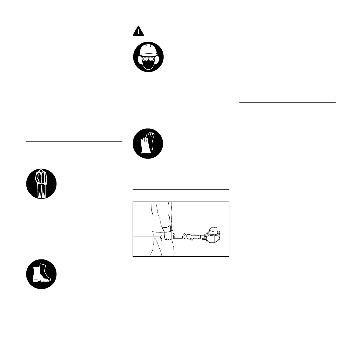
Clothing and equipment
Wear proper protective clothing and
equipment.
Clothing must be sturdy
but allow complete freedom of movement. Wear
snug-fitting clothing, e.g.
an overall and jacket
combination, do not wear
a work coat.
Do not wear clothing which could
become trapped in wood, brush or
moving parts of the machine. Do not
wear a scarf, necktie or jewelry. Tie up
and confine long hair above your
shoulders.
Wear cut protection
safety boots with non-slip
soles and steel toe caps.
WARNING
To reduce the risk of eye
injuries, wear close-fitting safety glasses in
accordance with European Standard EN 166.
Make sure the safety
glasses are a snug fit.
Wear "personal" sound protection, e.g.
ear defenders.
Wear a safety hard hat where there is a
danger of head injuries from falling
objects.
Wear sturdy protective
gloves made of a resistant material (e. g.
leather).
STIHL can supply a comprehensive
range of personal protective equipment.
Transporting the machine
Always stop the engine.
Always fit the chain scabbard – even
when you carry the power tool for short
distances.
Ensure that the power tool is always well
balanced and hold it by the shaft for
carrying.
Do not touch hot parts of the machine risk of burn injury!
By vehicle: When transporting in a
vehicle, properly secure your machine to
prevent turnover, damage and fuel
spillage.
Before starting
Check that your power tool is properly
assembled and in good condition – refer
to appropriate chapters in the
KombiEngine and KombiTool user
manuals.
– Correctly mounted guide bar
– Correctly tensioned saw chain
– Never attempt to modify the controls
or safety devices
– Keep the handles dry and clean –
free from oil and dirt – this is
important for safe control of the
machine
– Adjust carrying harness and
handles in accordance with body
height. Observe the chapter "Fitting
the Harness"
To reduce the risk of personal injury, do
not operate your power tool if it is
damaged or not properly assembled!
To prepare for emergencies when using
a harness: Practice setting down the
machine quickly. To avoid damage, do
not throw the machine to the ground
when practicing.
HT-KM
3

English
473BA007 KN
15m (50ft)
15m (50ft)
See also notes on "Before Starting" in
the user manual of the KombiEngine you
are using.
Holding and guiding the machine
Make sure you always have good
balance and secure footing.
Always hold your power tool firmly with
both hands:
Right hand on control handle, left hand
on the loop handle or handle hose, even
if you are left-handed. Wrap your fingers
and thumbs around the handles.
With the KM 94 R KombiEngine, always
use the handle hose of the KombiTool
as the left handle.
While working
In the event of impending danger or in
an emergency, switch off the engine
immediately by moving the slide control
/ stop switch/button to 0 or STOP.
This power tool is not
insulated. Keep at least
15 m away from electric
power lines – Danger of
fatal electric shock!
Do not allow other persons within a
radius of 15 m of your own position due
to falling branches and ejected wood
particles – Risk of injury! This distance
must also be maintained in relation to
objects (vehicles, window panes) – risk
of property damage!
Keep the bar nose at least 15 m away
from electric power lines . Electric
current may also arc over from highvoltage cables at greater distance. Have
the power switched off before starting
work in the immediate vicinity of power
lines.
Ensure that the engine idling speed is
correct. The saw chain must not move
when the throttle trigger has been
released.
Check and correct the idle speed setting
at regular intervals. If the saw chain still
rotates, have your dealer check your
machine and make proper adjustments
or repairs – see the user manual of the
KombiEngine.
Take special care in slippery, wet
conditions, in snow and on slopes,
uneven ground, etc. – Risk of slipping!
The gear head becomes
hot during operation. To
reduce the risk of burn
injury, do not touch the
gear housing!
Watch out for obstacles: tree stumps,
roots – risk of tripping or stumbling!
Make sure you always have good
balance and secure footing.
When working at heights:
– Always use a lift bucket
– Never use the machine while
standing on a ladder or in a tree
– Never work on an insecure support
– Never use the machine with just one
hand
Be particularly alert and cautious when
wearing hearing protection because
your ability to hear warnings (shouts,
alarms, etc.) is restricted.
Take breaks when you start getting tired
or feeling fatigue – risk of accidents!
4
HT-KM

English
max
473BA008 KN
Work calmly and carefully – in daylight
conditions and only when visibility is
good. Proceed with caution, do not put
others in danger.
Dust (e. g., sawdust), fumes and smoke
produced while using the machine may
be hazardous to health. If dust levels are
high, wear a suitable respirator.
Do not touch the saw chain while the
engine is running. If the saw chain
becomes jammed by an obstruction,
switch off the engine immediately before
attempting to remove the obstruction –
risk of injury.
Opening the throttle while the saw chain
is blocked increases the load and
reduces engine speed. The clutch then
slips continuously and this causes
overheating and damage to important
components (e.g. clutch, polymer
housing components) – and this can
increase the risk of injury from the saw
chain moving while the engine is idling.
If your power tool is subjected to
unusually high loads for which it was not
designed (e.g. heavy impact or a fall),
always check that it is in good condition
before continuing work – see also
"Before Starting". Make sure the safety
devices are working properly. Never use
a power tool that is no longer safe to
operate. In case of doubt, contact a
dealer.
To reduce the risk of injury, switch off the
engine before changing the saw chain.
If you use a harness, ensure that the
exhaust gas flow is diverted away from
your body – Risk of fire!
Limbing
Hold the power tool at an angle. Do not
stand directly underneath the limb being
cut. Do not exceed an angle of 60° from
the horizontal. Watch for falling wood.
Keep the work area clear – remove
interfering limbs and brush.
Before sawing branches, establish an
escape route and remove all obstacles.
0000003462_002
When performing the separating cut,
position the bar against the branch near
the hook. This will prevent the power tool
from making jolting movements when
you start the separating cut.
Start the cut with the saw chain at full
throttle.
Always cut with a correctly sharpened,
properly tensioned saw chain – the
depth gauge setting must not be too
large.
Perform cross-cut from the top
downward to avoid the chain pinching in
the cut.
If branch is thick or heavy, make a
relieving cut – see chapter on "Using the
Pole Pruner".
Exercise extreme caution when sawing
branches under tension – Risk of injury!
Always make a relieving cut on the
compression side first and then perform
the bucking cut at the tension side.
Be careful when cutting splintered wood
– Risk of injury from ejected pieces of
wood!
If working on a slope, always stand uphill
or to the side of the branch which is to be
sawn. Watch out for rolling branches.
HT-KM
5

English
Note when reaching the end of a cut that
the power tool is no longer supported by
the guide bar in the cut. The user must
bear the weight of the machine – risk of
loss of control!
Always pull the power tool out of the cut
with the saw chain running.
Use the power tool for limbing and
pruning only, not for felling – Risk of
accidents!
Keep the saw chain away from any
foreign objects: Stones, nails, etc. may
be ejected and damage the saw chain.
If a rotating saw chain hits a stone or
another hard object, sparks may be
generated which may ignite easily
flammable materials under certain
conditions. Also dried-out plants and
brushwood are combustible, above all in
hot and dry weather. If there is a risk of
fire, do not use your pole pruner near
easily flammable materials, dry plants or
scrub. It is mandatory that you ask the
responsible forestry office about the
current fire hazard.
Maintenance and Repairs
Service the machine regularly. Do not
attempt any maintenance or repair work
not described in the KombiTool and
KombiEngine instruction manuals. Have
all other work performed by a servicing
dealer.
STIHL recommends that you have
servicing and repair work carried out
exclusively by an authorized STIHL
servicing dealer. STIHL dealers are
regularly given the opportunity to attend
training courses and are supplied with
the necessary technical information.
Only use high-quality replacement parts
in order to avoid the risk of accidents
and damage to the machine. If you have
any questions in this respect, consult a
servicing dealer.
STIHL recommends the use of genuine
STIHL replacement parts. They are
specifically designed to match your
model and meet your performance
requirements.
To reduce the risk of injury,always shut
off the enginebefore carrying out any
maintenance or repairs or cleaning the
machine. – Exception: Carburetor and
idle speed adjustments.
Stopping the engine
– before checking chain tension.
– before retensioning the chain.
– before replacing the chain.
– before rectifying problems.
Observe sharpening instructions – keep
the chain and guide bar in good
condition at all times for safe and correct
handling of the saw. The chain must be
properly sharpened, tensioned and well
lubricated.
Always change the chain, guide bar and
sprocket in good time.
Store chain lubricant in properly
labelled, safety-type canisters only.
Using the Unit
Preparation
N Wear suitable protective clothing,
observe safety precautions
N Starting the engine
N Fitting the harness
Cutting sequence
To allow branches to free fall, always cut
the lower branches first. Prune heavy
branches (large diameter) in several
controllable pieces.
WARNING
Never stand directly underneath the
branch you are cutting – be wary of
falling branches. Note that a branch may
spring back at you after it hits the ground
– risk of injury
Disposal
Do not throw cuttings into the garbage
can – they can be composted.
Working technique
Hold the control handle with your right
hand, and the loop handle with your left
hand. Your left arm should be extended
to the most comfortable position.
6
HT-KM

English
402BA012 KN
2
1
0000003451_002
3
4
A
390BA024 KN
The shaft should always be held at an
angle of 60° or less.
The least tiring working position is a tool
angle of 60°.
Any lesser angle may be used to suit the
situation.
Cross-cut
downwards. The saw chain can be
positioned precisely using the gauge
bar.
Relieving cut
To avoid tearing the bark on thick
branches, always start by performing a
N relieving cut (1) on the underside of
the branch. To do this, position the
cutting attachment and guide it
down to the bar nose in an arc.
N Perform the cross-cut (2) – position
the bar with the hook against the
branch and then perform the crosscut
0000003462_003
Flush-cutting thick branches
If the branch diameter is more than
10 cm (4 in), first
N perform the undercut (3) and then
cross-cut at a distance of about
20 cm/8 in (A) from the final cut.
Then carry out the flush-cut (4),
starting with a relieving cut and
finishing with a cross-cut
To avoid pinching the bar in the cut,
position the cutting attachment with the
hook against the branch and then
perform the cross-cut from the top
HT-KM
7
English
402BA013 KN
402BA032 KN
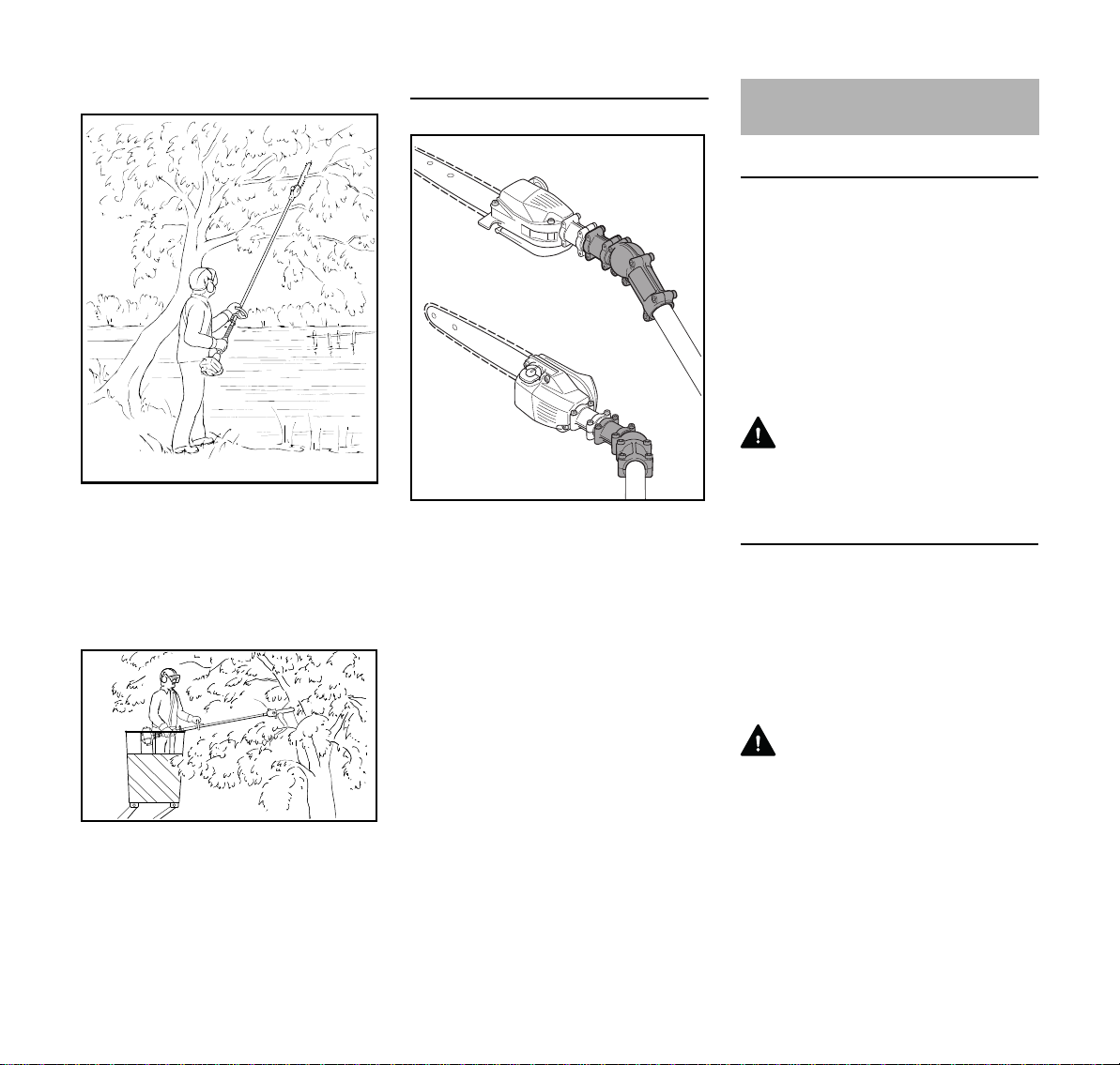
Cutting above obstacles
The machine's long reach makes it
possible to prune branches that are
overhanging obstacles, such as rivers or
lakes. The tool angle in this case
depends on the position of the branch.
Cutting from a lift bucket
30° angle drive (special accessory)
1
2
The angle drive keeps the cutting
attachment at an angle of 30° to the
shaft.
The angle drive may be adjusted on the
shaft to the following positions only:
1 for cross-cutting vertical branches
and bushes
2 for a better view of the cutting
attachment
Approved KombiEngines
KombiEngines
Only use KombiEngines supplied or
explicitly approved by STIHL for use with
the attachment.
This KombiTool may be operated only in
combination with the following
KombiEngines:
STIHL KM 56 R, KM 85 R KM 94 R,
KM 111 R, KM 131 R, KMA 130 R,
KMA 135 R
WARNING
Loop-handled machines must be
equipped with a barrier bar.
0000097201_001
Brushcutters with split boom
The KombiTool can also be fitted to
STIHL brushcutters with a split shaft (Tmodels) (basic power tools).
This KombiTool can therefore also be
used on the following machine:
STIHL FR 131 T
The machine's long reach enables
cutting to be performed next to the trunk
without the risk of the lift bucket
damaging other branches. The tool
angle in this case depends on the
position of the branch.
8
WARNING
Refer to the User Manual of the power
tool for use of the barrier bar.
HT-KM

English
413BA014 KN
002BA248 KN
A
402BA002 KN
0000097202_001
12
Assembling the Unit
N Pull the protective caps off the ends
of the shaft and keep them in a safe
place for later use – see "Storing the
Machine"
NOTICE
The plug may come out of the drive tube
when you pull off the cap. Push it back
into the shaft as far as it will go.
Mounting the gearbox
N Apply a mark to the shaft at distance
(A) of 50 mm (2 in.)
N Push the gearbox (1) onto the
shaft (2) as far as stop – turn the
gearbox back and forth until the
square end of the shaft engages
The gearbox is correctly positioned
when the end of its housing reaches or
covers the mark (arrow).
1
0000097204_001
N Line up the gearbox (1) so that the
chain sprocket cover is exactly
vertical and the lug (arrow) on the
end of the drive tube faces up
N Tighten down the clamp screws (3)
in the following sequence:
– tighten the left screw moderately
– tighten the right screw moderately
– tighten down the left screw firmly
– tighten down the right screw firmly
HT-KM
3
1
3
0000097203_001
N Insert the clamp screws (3) as far as
it will go
9

English
1
002BA326 KN
2
3
002BA327 KN
4
001BA248 KN
1
2
3
a
001BA244 KN
Mounting the KombiTool
N Push the lug (1) on the drive tube
into the slot (2) in the coupling
sleeve as far as stop.
When correctly installed, the red line (3)
(arrow point) must be flush with the end
of the coupling sleeve.
N Tighten down the star knob (4)
firmly.
Cutting Attachment
A cutting attachment consists of the saw
chain, guide bar and chain sprocket.
The cutting attachment that comes
standard is designed to exactly match
the pole pruner.
– The pitch (t) of the saw chain (1),
chain sprocket and the nose
sprocket of the Rollomatic guide bar
must match.
– The drive link gauge (2) of the saw
chain (1) must match the groove
width of the guide bar (3).
If non-matching components are used,
the cutting attachment may be damaged
beyond repair after a short period of
operation.
Chain Scabbard
The scope of supply includes a bar
scabbard that matches the cutting
attachment.
If guide bars of different lengths are
mounted to the pole pruner, always use
a chain scabbard of the correct length
which covers the complete guide bar.
The length of the matching guide bars is
marked on the side of the chain
scabbard.
Removing the KombiTool
N Reverse the above sequence to
remove the drive tube.
10
HT-KM

English
0000003452_002
2
1
0000097194_001
390BA003 KN
1
5
390BA044 KN
4
3
Mounting the Bar and Chain
Removing the chain sprocket cover
N Unscrew the nut and remove the
cover
N Turn the screw (1)
counterclockwise until the tensioner
slide (2) butts against the left end of
the housing slot, then back it off 5
full turns
Fitting the saw chain
WARNING
Wear work gloves to protect your hands
from the sharp cutters.
N Fit the saw chain – start at the bar
nose
N Fit the guide bar over the screw (3)
and engage peg of tensioner slide in
the hole (4) – place the saw chain
over the chain sprocket (5) at the
same time
N Turn the tensioning screw (1)
clockwise until there is very little
chain sag on the underside of the
bar – and the drive link tangs are
engaged in the bar groove
N Refit the cover and screw on the nut
finger-tight
N Go to chapter on "Tensioning the
Saw Chain"
HT-KM
11

English
1
390BA045 KN
390BA046 KN
Tensioning the Chain
Re-tensioning during cutting work:
N Shut off the engine
N Loosen nuts
N Raise the guide bar at the nose
N Use the screwdriver to turn the
screw (1) to the right until the saw
chain rests against the underside of
the guide bar
N Raise the guide bar further and
tighten the nuts securely
N Next step: Continue with "Checking
Chain Tension"
A new saw chain has to be re-tensioned
more often than one that has been in
use for some time.
N Check chain tension frequently –
see chapter on "Operating
Instructions"
Checking Chain Tension
N Shut off the engine
N Wear work gloves to protect your
hands
N The saw chain must fit snugly
against the underside of the bar and
it must still be possible to pull the
chain along the guide bar by hand
N If necessary, re-tension the saw
chain
A new saw chain has to be re-tensioned
more often than one that has been in
use for some time.
N Check chain tension frequently –
see chapter on "Operating
Instructions"
Chain Lubricant
For automatic and reliable lubrication of
the chain and guide bar – use only an
environmentally compatible quality
chain and bar lubricant. Rapidly
biodegradable STIHL BioPlus is
recommended.
NOTICE
Biological chain oil must be resistant to
aging (e.g. STIHL BioPlus), since it will
otherwise quickly turn to resin. This
results in hard deposits that are difficult
to remove, especially in the area of the
chain drive and chain. It may even cause
the oil pump to seize.
The service life of the chain and guide
bar depends on the quality of the
lubricant. It is therefore essential to use
only a specially formulated chain
lubricant.
WARNING
Do not use waste oil. Renewed contact
with waste oil can cause skin cancer.
Moreover, waste oil is environmentally
harmful.
NOTICE
Waste oil does not have the necessary
lubricating properties and is unsuitable
for chain lubrication.
12
HT-KM

English
0000097195 001
0000,GXX-0135-A0 KN
0000-GXX-0136-A0
0000-GXX-0137-A0 KN
0000-GXX-0138-A0 KN
0000-GXX-0137-A0 KN
Filling Chain Oil Tank
NOTICE
A full chain oil tank is sufficient for only
half a tankful of fuel. Check the oil level
regularly during cutting work. Never
allow the oil tank to run dry
Preparations
N Thoroughly clean the fuel cap and
the area around it to ensure that no
dirt falls into the tank
N Position the machine so that the fuel
cap is facing upwards
To open:
N Open the bracket
N Twist fuel cap (ca. 1/4 turn)
N Remove the fuel cap
Filling up with chain oil
N Fill up with chain oil
Take care not to spill chain oil during
refilling and do not overfill the tank.
STIHL recommends use of the STIHL
filling system for chain oil (special
accessory).
To close:
HT-KM
Markings on fuel cap and oil tank must
align
Clip is in an upright position:
N Fit the fuel cap – marks on the fuel
cap and oil tank must line up.
N Push the fuel cap down as far as it
will go
13

English
0000-GXX-0139-A0 KN
0000-GXX-0140-A0 KN
0000-GXX-0141-A0 KN
0000-GX-0142 A0 KN
002BA584 KN
1
0000-GXX-0136-A0
N Hold the fuel cap down and twist it
clockwise until it engages
Then the markings on fuel cap and oil
tank will align
N Close the bracket lock
The fuel cap is locked
If the oil level in the tank does not go
down, the reason may be a problem in
the oil supply system: Check chain
lubrication, clean the oilways, contact
your dealer for assistance if necessary.
STIHL recommends that maintenance
and repair work be carried out only by
authorised STIHL dealers.
If the fuel cap will not lock onto the oil
tank
The base of the fuel cap is tilted in
relation to the upper part.
N Remove the fuel cap from the oil
tank and look at it from above
left: Base of fuel cap is tilted –
interior marking (1) is aligned
with the exterior marking
right: Bottom of the fuel cap in cor-
rect position – inner mark is
under the grip. It does not
align with the exterior
marking
N Fit fuel cap and twist it
counterclockwise until it engages in
the seat of the filling port
N Continue to twist the fuel cap
counterclockwise (approx. 1/4 turn)
– this will twist the base of the cap
into the correct position
N Twist the fuel cap clockwise and
close it – see section "Closing"
14
HT-KM

English
390BA048 KN
1
0000-GXX-0503-A0
2
Checking Chain Lubrication
The saw chain must always throw off a
small amount of oil.
NOTICE
Never operate without chain lubrication.
If the chain runs dry, the whole cutting
attachment will be irretrievably damaged
within a very short time. Always check
chain lubrication and the oil level in the
tank before starting work.
Every new chain has to be broken in for
about 2 to 3 minutes.
After breaking in the chain, check chain
tension and adjust if necessary – see
"Checking Chain Tension".
Fitting the Harness
Not all basic power tools are equipped
with a shoulder strap and carrying ring.
N Fit the carrying ring – see "Mounting
the Attachment".
The shoulder strap is available as a
special accessory.
The type of carrying ring, shoulder strap
and carabiner depends on the market
and the basic power tool.
Shoulder Strap
Attaching Machine to Shoulder Strap
2
1
1
2
N Attach the carabiner (1) to the
carrying ring (2) on the shaft.
Disconnecting Machine from Shoulder
Strap
1
1
2
2
N Press down the bar on the
carabiner (1) and pull the carrying
ring (2) out of the carabiner.
0000-GXX 1056-A0
0000-GXX 1058-A0
HT-KM
Throwing Off the Machine
WARNING
N Put on the shoulder strap (1).
N Adjust the length of the strap – with
the machine attached, the
carabiner (2) must be about a
hand's width below your right hip.
The machine must be quickly thrown off
in the event of imminent danger. To
throw off the machine, use the
procedure described under
"Disconnecting Machine from Shoulder
Strap". Practice removing and putting
down the machine as you would in an
15

English
402BA039 KN
402BA040 KN
emergency. To avoid damage, do not
throw the machine to the ground when
practicing.
Starting / Stopping the
Engine
Starting the Engine
Always follow the operating instructions
for the KombiEngine and basic power
tool.
N Remove the chain guard.
Check that the chain is not touching the
ground or any other obstacles.
N Position the unit securely for
starting: Put the powerhead on the
ground so that it rests on the engine
support. Rest the hook on the
cutting attachment on a raised
support, e.g. a mound or branch.
N Make sure you have a firm footing,
either standing, stooping or
kneeling.
N Hold the machine with you left hand
and press it down firmly – do not
touch the controls on the control
handle – see KombiEngine or basic
power tool instruction manual.
Alternative method of starting
N Hang the cutting attachment on a
branch so that it is held by the hook.
N Make sure you have a safe and
secure footing.
N Hold the machine with you left hand
and press it down firmly – do not
touch the controls on the control
handle – see KombiEngine or basic
power tool instruction manual.
WARNING
The saw chain may begin to run as soon
as the engine starts. For this reason, blip
the throttle after starting – the engine
returns to idling speed.
The starting procedure is now as
described in the instruction manual of
the KombiEngine or basic power tool
you are using.
Stopping the Engine
N See KombiEngine or basic power
tool instruction manual.
16
NOTICE
Do not stand or kneel on the drive tube.
HT-KM

English
Operating Instructions Taking Care of the Guide Bar
During Operation
Check chain tension frequently
A new chain has to be retensioned more
often than one that has been in use for
some time.
Chain cold
Tension is correct when the chain fits
snugly against the underside of the bar
and can still be pulled along the bar by
hand. Retension if necessary – see
"Tensioning the Saw Chain".
Chain at operating temperature
The chain stretches and begins to sag.
The drive links must not come out of the
bar groove – the chain may otherwise
jump off the bar. Retension the chain –
see "Tensioning the Saw Chain".
NOTICE
The chain contracts as it cools down. If it
is not slackened off, it can damage the
gear shaft and bearings.
After Finishing Work
N Slacken off the chain if you have
retensioned it at operating
temperature during cutting work.
NOTICE
Always slacken off the chain after
finishing work. The chain contracts as it
cools down. If it is not slackened off, it
can damage the gear shaft and
bearings.
Storing for a long period
See chapter on "Storing the Machine"
2
1
N Turn the bar over – every time you
sharpen the chain and every time
you replace the chain – this helps
avoid one-sided wear, especially at
the nose and underside of the bar
N Regularly clean the oil inlet hole (1),
the oilway (2) and the bar
groove (3)
N Measure the groove depth – with the
scale on the filing gauge (special
accessory) – in the area used most
for cutting
Chain type Chain pitch Minimum
Picco 3/8" P 5.0 mm
Picco 1/4" P 4.0 mm
If groove depth is less than specified:
N Replace the guide bar
3
groove depth
0000097197_001
HT-KM
17

English
a
000BA054 KN
The drive link tangs will otherwise
scrape along the bottom of the groove –
the cutters and tie straps will not ride on
the bar rails.
Storing the Machine Checking and Replacing the
Chain Sprocket
For periods of 30 days or longer
N Remove the saw chain and guide
bar, clean them and spray with
corrosion inhibiting oil.
N If you use a biological chain and bar
lubricant, e.g. STIHL BioPlus,
completely fill the chain oil tank.
N If the KombiTool is removed from
the KombiEngine and stored
separately: Fit the protective cap on
the drive tube to avoid dirt getting
into the coupling.
N Store the machine in a dry, high or
locked location – out of the reach of
children and other unauthorized
persons.
N Remove chain sprocket cover, saw
chain and guide bar
Replace the chain sprocket
– replace after using two saw chains
or sooner
– if the wear marks (a) on the sprocket
are deeper than approx. 0.5 mm
(0.02 in) since this would reduce the
service life of the saw chain. You
can use a gauge (special
accessory) to check the depth of the
wear marks
Using two saw chains in alternation
helps preserve the chain sprocket.
STIHL recommends the use of original
STIHL chain sprockets.
18
HT-KM

English
689BA027 KN
a
A
B
689BA021 KN
The chain sprocket is driven via a friction
clutch. Have the chain sprocket replaced
by an authorized dealer.
STIHL recommends that maintenance
and repair work be carried out only by
authorized STIHL dealers.
HT-KM
Maintaining and Sharpening
the Saw Chain
Cutting effortlessly with a correctly
sharpened chain
A properly sharpened chain slices
through wood effortlessly and requires
very little feed pressure.
Do not work with a dull or damaged
chain as it will increase the physical
effort required, produce unsatisfactory
results and a higher rate of wear.
N Clean the chain.
N Check the chain for cracks in the
0000097198_001
links and damaged rivets.
N Replace any damaged or worn
parts of the chain and match the
new parts to the shape and size of
the original parts.
Carbide-tipped saw chains (Duro) are
particularly wear resistant. STIHL
recommends you have your chain
resharpened by a STIHL servicing
dealer.
WARNING
It is absolutely essential to comply with
the angles and dimensions specified
below. If the saw chain is incorrectly
sharpened – and in particular if the depth
gauge is set too low – there is an
increased risk of kickback, with resulting
risk of injury.
The saw chain cannot be locked in place
on the guide bar. Therefore, it is best to
remove the chain from the bar and
resharpen it on a workshop sharpening
tool (FG 2, HOS, USG).
Chain pitch
The chain pitch (a) is marked on the
depth gauge end of each cutter.
Mark (a) Chain pitch
inch mm
7 1/4 P 6,35
1 or 1/4 1/4 6,35
6, P or PM 3/8 P 9,32
2 or 325 0.325 8,25
3 or 3/8 3/8 9,32
Select file diameter according to chain
pitch – see table “Sharpening Tools”.
You must observe certain angles when
resharpening the chain cutter.
Filing and side plate angles
A Filing angle
19

English
689BA025 KN
001BA203 KN
689BA018 KN
90°
689BA043 KN
STIHL saw chains are sharpened to a
filing angle of 30°. Exceptions are
ripping chains with a filing angle of 10°.
Ripping chains have an X in their
designations.
B Side plate angle
The correct side plate angle is obtained
automatically if you use the prescribed
file holder and file diameter.
Cutter shapes Angle (°)
AB
Micro = semi chisel cutter,
30 75
e.g. 63 PM3, 26 RM3,
71 PM3
Super = chisel cutter, e.g.
30 60
63 PS3, 26 RS, 36 RS3
Ripping chain, e.g.
10 75
63 PMX, 36 RMX
The angles must be the same on all
cutters. If the angles are uneven: Chain
will run roughly, not in a straight line,
wear quickly and finally break.
File holder
N Use a file holder
A file holder must be used for manual
resharpening (see table "Sharpening
Tools"). The correct filing angles are
marked on the file holder.
Use only special saw chain sharpening
files. Other files have the wrong shape
and cut.
For checking angles
Use a STlHL filing gauge (special
accessory, see table "Sharpening
Tools"). This is a universal tool for
checking the filing and side plate angles,
depth gauge setting, cutter length and
groove depth. It also cleans the guide
bar groove and oil inlet holes.
File correctly
N Select sharpening tools according
to chain pitch.
N If you use an FG 2, HOS or USG
sharpener: Remove the chain from
the bar and sharpen according to
the instructions supplied with the
tool.
N Clamp the bar in a vise if necessary.
N Sharpen the chain frequently, take
away as little metal as possible –
two or three strokes of the file are
usually enough.
N Hold the file horizontally (at a right
angle to the side of the guide bar)
and file according to the angles
marked on the file holder. Rest the
file holder on the top plate and depth
gauge.
N Always file from the inside to the
outside of the cutter.
N The file only sharpens on the
forward stroke – lift the file off the
cutter on the backstroke.
N Avoid touching the tie straps and
drive links with the file.
N Rotate the file at regular intervals
while filing to avoid one-sided wear.
N Use a piece of hardwood to remove
burrs from the cutting edge.
N Check angles with the filing gauge.
All cutters must be the same length.
20
HT-KM

English
689BA023 KN
a
2
689BA061 KN
1
689BA051 KN
689BA044 KN
If the cutters are not the same length,
they will have different heights. This
makes the chain run roughly and can
cause it to break.
N Find the shortest cutter and then file
all other cutters back to the same
length. It is best to have this work
done by a servicing dealer on an
electric grinder.
Depth gauge setting
The depth gauge determines the height
at which the cutter enters the wood and
thus the thickness of the chip removed.
a Specified distance or setting
between depth gauge and cutting
edge.
This setting may be increased by 0.2
mm (0.008") for cutting softwood in the
mild weather season – no frost.
Chain pitch Depth gauge
Setting (a)
inch (mm) mm (inch)
1/4 P (6,35) 0,45 (0.018)
1/4 (6,35) 0,65 (0.026)
3/8 P (9,32) 0,65 (0.026)
0.325 (8,25) 0,65 (0.026)
3/8 (9,32) 0,65 (0.026)
Lowering depth gauges
The depth gauge setting is reduced
when the chain is sharpened.
N Use a filing gauge to check the
setting every time you sharpen the
chain.
N Place a filing gauge (1) that
matches the chain pitch on the
chain and press it against the cutter
– if the depth gauge projects from
the filing gauge, the depth gauge
has to be lowered.
Saw chains with humped drive link (2) –
upper part of humped drive link (2) (with
service mark) is lowered along with the
depth gauge.
WARNING
The other parts of the humped drive link
must not be filed since this may increase
the kickback tendency of the power tool.
N File down the depth gauge until it is
level with the filing gauge.
N File the top of the depth gauge
parallel to the stamped service
marking (see arrow) – but do not
lower the highest point of the depth
gauge in this process.
WARNING
The kickback tendency of the machine is
increased if the depth gauges are too
low.
HT-KM
21

English
689BA052 KN
N After sharpening, clean the chain
thoroughly, remove filings or
grinding dust – lubricate the chain
thoroughly.
N Before a long out-of-service period,
clean the chain and store it in a welloiled condition.
N Place the filing gauge on the chain –
the highest point of the depth gauge
must be level with the filing gauge.
Sharpening Tools (special accessories)
Chain pitch Round file ^ Round file File holder Filing gauge Flat file Sharpening kit
inch (mm) mm (inch) Part No. Part No. Part No. Part No. Part No.
1/4 P (6,35) 3,2 (1/8) 5605 771 3206 5605 750 4300 0000 893 4005 0814 252 3356 5605 007 1000
1/4 (6,35) 4,0 (5/32) 5605 772 4006 5605 750 4327 1110 893 4000 0814 252 3356 5605 007 1027
3/8 P (9,32) 4,0 (5/32) 5605 772 4006 5605 750 4327 1110 893 4000 0814 252 3356 5605 007 1027
0.325 (8,25) 4,8 (3/16) 5605 772 4806 5605 750 4328 1110 893 4000 0814 252 3356 5605 007 1028
3/8 (9,32) 5,2 (13/64) 5605 772 5206 5605 750 4329 1110 893 4000 0814 252 3356 5605 007 1029
1)
consisting of file holder with round file, flat file and filing gauge
1)
22
HT-KM

Maintenance and Care
The following intervals apply for normal operating conditions. If your daily working
time is longer or operating conditions are difficult (very dusty work area, resin-rich
wood, tropical wood, etc.), shorten the specified intervals accordingly. If you only use
the tool occasionally, extend the intervals accordingly.
before starting work
after finishing work or daily
after each refueling stop
weekly
monthly
every 12 months
if problem
All accessible screws and nuts (not adjusting screws)
Chain lubrication Check X
Saw chain
Guide bar
Chain Sprocket
Safety labels Replace X
1)
STIHL recommends an authorized STIHL servicing dealer.
Re-tighten X
Inspect, also check sharpness XX
Check chain tension. XX
Sharpen X
Check (wear, damage) X
Clean and turn over XX
Deburr X
Replace XX
Check X
Have replaced by servicing dealer
1)
English
if damaged
as required
X
HT-KM
23

English
Minimize Wear and Avoid
Damage
Observing the instructions in this manual
and the KombiEngine manual helps
reduce the risk of unnecessary wear and
damage to the power tool.
The power tool must be operated,
maintained and stored with the due care
and attention described in these
instruction manuals.
The user is responsible for all damage
caused by non-observance of the safety
precautions, operating and maintenance
instructions. This includes in particular:
– Alterations or modifications to the
product not approved by STIHL.
– Using tools or accessories which
are neither approved or suitable for
the product or are of a poor quality.
– Using the product for purposes for
which it was not designed.
– Using the product for sports or
competitive events.
– Consequential damage caused by
continuing to use the product with
defective components.
Maintenance Work
servicing dealer. STIHL dealers are
regularly given the opportunity to attend
training courses and are supplied with
the necessary technical information.
If these maintenance operations are not
carried out as specified, the user
assumes responsibility for any damage
that may occur. Among other parts, this
includes:
– Corrosion and other consequential
damage resulting from improper
storage.
– Damage to the product resulting
from the use of poor quality
replacement parts.
Parts Subject to Wear and Tear
Some parts of the power tool are subject
to normal wear and tear even during
regular operation in accordance with
instructions and, depending on the type
and duration of use, have to be replaced
in good time. Among other things, this
includes:
– Saw chain, guide bar
– Chain sprocket
– Friction clutch
– Chain tensioner
All the operations described in the
chapter on "Maintenance and Care"
must be performed on a regular basis. If
these maintenance operations cannot
be performed by the owner, they should
be performed by a servicing dealer.
STIHL recommends that you have
servicing and repair work carried out
exclusively by an authorized STIHL
24
HT-KM

Main Parts
12
13
English
1 Saw chain
1
2
4
5
3
5
6
8
10
11
7
9
2 Guide bar
3 Oil tank
4 Oil tank cap
5 Shaft
6 Chain sprocket cover
7 Hook
8 Chain scabbard
9 Chain sprocket
10 Gauge bar
11 Chain tensioner
12 Sleeve
13 Handle hose
0000097205_002
HT-KM
25

English
Specifications
Chain lubrication
Fully automatic, speed-controlled oil
pump with rotary piston
Oil tank capacity: 220 cm3 (0.22 l)
Weight
Cutting attachment
3/8" P with drive
tube: 2.1 kg
Cutting attachment
1/4" P with drive
tube: 2.0 kg
Cutting attachment
The actual cutting length may be less
than the specified cutting length.
Guide bar Rollo Light 01
Blade length: 25, 30, 35 cm
Pitch: 3/8" P (9.32 mm)
Groove width: 1.1 mm
Guide bar Rollo Light 01
Blade length: 25, 30, 35 cm
Pitch: 1/4" P (6.35 mm)
Groove width: 1.1 mm
Saw chain 3/8" P
Picco Micro Mini 3 (61 PMM3)
Type 3610
Pitch: 3/8" P (9.32 mm)
Drive link gauge: 1.1 mm
Saw chain 1/4" P
Picco Micro3 (71PM3) Type 3670
Pitch: 1/4" P (6.35 mm)
Drive link gauge: 1.1 mm
Chain sprocket
7-tooth for 3/8" P
8-tooth for 1/4" P
Sound and Vibration Levels
Noise and vibration data measurements
on power tools with the HT-KM
KombiTool include idling and rated
maximum speed with the same duration
of exposure.
For further details on compliance with
Vibration Directive 2002/44/EC, see
www.stihl.com/vib
Sound pressure level L
peq
in
accordance with ISO 22868
KM 56 R 90 dB(A)
KM 85 R 92 dB(A)
KM 94 R: 91 dB(A)
KM 111 R: 93 dB(A)
KM 131 R: 92 dB(A)
FR 131 T: 98 dB(A)
KMA 130 R: 90 dB(A)
KMA 135 R: 84 dB(A)
Sound power level L
in accordance
w
with ISO 22868
KM 56 R 106 dB(A)
KM 85 R 109 dB(A)
KM 94 R: 107 dB(A)
KM 111 R: 108 dB(A)
KM 131 R: 109 dB(A)
FR 131 T: 109 dB(A)
KMA 130 R: 100 dB(A)
KMA 135 R: 94 dB(A)
Vibration level a
in accordance with
hv,eq
ISO 22867
Handle,
left
KM 56 R 6.8 m/s
KM 85 R 4.7 m/s25.2 m/s
KM 94 R: 4.0 m/s24.7 m/s
KM 111 R: 3.9 m/s23.4 m/s
KM 131 R: 4.8 m/s24.0 m/s
FR 131 T: 2.7 m/s21.7 m/s
KMA 130 R 2.5 m/s22.2 m/s
KMA 135 R 2.5 m/s22.0 m/s
2
Handle,
right
4.8 m/s
2
2
2
2
2
2
2
2
The K-factor in accordance with
Directive 2006/42/EC is 2.0 dB(A) for
the sound pressure level and sound
power level; the K-factor in accordance
with Directive 2006/42/EC is 2.0 m/s
2
for the vibration level.
REACH
REACH is an EC regulation and stands
for the Registration, Evaluation,
Authorization and Restriction of
Chemical substances.
26
HT-KM

English
000BA073 KN
For information on compliance with the
REACH regulation (EC) No. 1907/2006
see
www.stihl.com/reach
Maintenance and Repairs Disposal
Users of this machine may only carry out
the maintenance and service work
described in this user manual. All other
repairs must be carried out by a
servicing dealer.
STIHL recommends that you have
servicing and repair work carried out
exclusively by an authorized STIHL
servicing dealer. STIHL dealers are
regularly given the opportunity to attend
training courses and are supplied with
the necessary technical information.
When repairing the machine, only use
replacement parts which have been
approved by STIHL for this power tool or
are technically identical. Only use highquality replacement parts in order to
avoid the risk of accidents and damage
to the machine.
STIHL recommends the use of original
STIHL replacement parts.
Original STIHL parts can be identified by
the STIHL part number, the {
logo and the STIHL parts symbol K
(the symbol may appear alone on small
parts).
Contact the local authorities or your
STIHL servicing dealer for information
on disposal.
Improper disposal can be harmful to
health and pollute the environment.
N Take STIHL products including
packaging to a suitable collection
point for recycling in accordance
with local regulations.
N Do not dispose with domestic
waste.
HT-KM
27

English
EC Declaration of Conformity
ANDREAS STIHL AG & Co. KG
Badstr. 115
D-71336 Waiblingen
Germany
declare under our sole responsibility that
Designation: KombiTool Pole
Pruner
Make: STIHL
Series: HT-KM
Serial identification
number: 4182
conforms to the relevant provisions of
Directive 2006/42/EC and has been
developed and manufactured in
compliance with the following standards
in the versions valid on the date of
production:
EN ISO 12100, EN ISO 11680-1 (in
conjunction with the specified KM
models).
EN ISO 12100, EN 60745-1, EN 607452-13 (in conjunction with KMA 130 R)
EN ISO 12100, EN 62841-1, EN 628414-1, ISO 11680-1 (in conjunction with
KMA 135 R)
EN ISO 12100, EN ISO 11680-2 (in
conjunction with the specified FR
models).
EC Type Examination
The EC type examination was carried
out by
for HT-KM with KM 56 R, KM 94 R at:
DPLF Deutsche Prüf- und
Zertifizierungsstelle für Land- und
Forsttechnik
(NB 0363)
Spremberger Str. 1
D-64823 Groß-Umstadt
Certification No.
HT-KM with
KM 56 R: D-EG 16.00573/01
HT-KM with
KM 94 R: D-EG 16.00574/01
HT-KM with KM 111 R, KM 131 R,
FR 131 T
TÜV Süd Product Service GmbH
(NB 0123)
Ridlerstrasse 65
D-80339 München
Certification No.
HT-KM with
KM 111 R:
HT-KM with
KM 131 R:
HT-KM with
FR 131 T:
HT-KM with KMA'
VDE Prüf- u.Zertifizierungsinstitut
(NB 0366)
Merianstraße 28
D-63069 Offenbach
HT-KM with
KMA 130 R: 40047718
HT-KM with
KMA 135 R: 40051625
Technical documents deposited at:
M6A 18 03 10127 508
M6A 18 03 10127 508
M6A 17 12 10127 500
Certification No.
ANDREAS STIHL AG & Co. KG
Produktzulassung
The year of manufacture is specified on
the power tool.
Waiblingen, 2022-01-14
ANDREAS STIHL AG & Co. KG
pp
Dr. Jürgen Hoffmann
Director Product Certification &
Regulatory Affairs
28
HT-KM

UKCA Declaration of
Conformity
ANDREAS STIHL AG & Co. KG
Badstr. 115
D-71336 Waiblingen
Germany
declares under our sole responsibility
that
Designation: KombiTool Pole
Pruner
Make: STIHL
Series: HT-KM
Serial identification
number: 4182
conforms to the relevant provisions of
the UK Supply of Machinery (Safety)
Regulations 2008 and has been
manufactured in compliance with the
following standards in the versions valid
on the date of production:
EN ISO 12100, EN ISO 11680-1 (in
conjunction with the specified KM
models).
EN ISO 12100, EN 60745-1, EN 607452-13 (in conjunction with KMA 130 R)
EN ISO 12100, EN 62841-1, EN 628414-1, ISO 11680-1 (in conjunction with
KMA 135 R)
EN ISO 12100, EN ISO 11680-2 (in
conjunction with the specified FR
models)
Type Examination
The type examination was carried out by
HT-KM with KM 56 R, KM 94 R,
KM 111 R, KM 131 R, FR 131 T
Intertek Testing & Certification Ltd,
Academy Place, 1 – 9 Brook Street,
Brentwood Essex, CM14 5NQ, United
Kingdom
Certification No.
HT-KM with
KM 56 R: ITS UK MCR 31
HT-KM with
KM 94 R: ITS UK MCR 32
HT-KM with
KM 111 R:
HT-KM with
KM 131 R:
HT-KM with
FR 131 T:
HT-KM with KMA
Intertek Testing & Certification Ltd,
Academy Place, 1 – 9 Brook Street,
Brentwood Essex, CM14 5NQ, United
Kingdom
HT-KM with
KMA130R: ITSUKMCR40
HT-KM with
KMA135R: ITSUKMCR41
Technical documents deposited at:
ANDREAS STIHL AG & Co. KG
The year of manufacture is indicated on
the power tool.
ITS UK MCR 74
ITS UK MCR 74
ITS UK MCR 72
Certification No.
Waiblingen, 2022-03-31
ANDREAS STIHL AG & Co. KG
pp
Dr. Jürgen Hoffmann
Director Product Certification &
Regulatory Affairs

0458-473-0121-D
englisch
G
www.stihl.com
*04584730121D*
0458-473-0121-D
 Loading...