

Page 1

FS 25-4, 65-4
Contents
1. Safety Precautions 1
2. Introduction 2
3. Specifications 3
3.1 Engine 3
3.2 Fuel System 3
3.3 Ignition System 4
3.4 Gearhead 4
3.5 Special Accessories 4
3.5.1 For User 4
3.6 Dimensions and
Wear Limits 5
3.7 Tightening Torques 6
4. Troubleshooting 7
5. Clutch 10
5.1 Removing and
Disassembling 10
5.2 Assembling and
Installing 10
6. Engine 11
6.1 Checking/Adjusting
Valve Clearance 11
6.2 Checking Oil Level/
Changing Oil 13
6.3 Exhaust Muffler 14
6.4 Rocker Arms/Pushrods 14
6.5 Cam Followers 15
6.6 Cam Gear 15
6.7 Diaphragm 15
6.8 Crankcase,
Lower Half 16
6.9 Crankshaft 17
6.10 Valves/Valve Springs 18
6.11 Crankcase/Cylinder 18
9. Throttle Control 26
9.1 Throttle Trigger/Interlock
Lever (Bike Handle) 26
9.2 Contact Springs/Detent
Spring in Control Handle
(Bike Handle) 27
9.3 Throttle Trigger/Interlock
Lever (Loop Handle) 27
9.4 Slide Control
(Loop Handle) 28
9.5 Throttle Cable 29
9.5.1 Replacing 29
9.5.2 Adjusting 30
10. AV System 30
11. Fuel System 32
11.1 Air Filter 32
11.2 Carburetor 32
11.2.1 Leakage Test 32
11.2.2 Removing/Installing 33
11.2.3 Adjusting Idle Speed 34
11.3 Tank Vent 35
11.4 Pickup Body 35
11.5 Fuel Hoses 36
11.6 Fuel Tank 37
12. Shaft 38
12.1 Bike Handle 38
12.2 Loop Handle 38
12.3 Drive Shaft/
Flexible Liner 39
12.4 Drive Tube 40
13. Cutting Tool Drive 41
13.1 Gearhead 41
13.2 Clutch Drum 41
1. Safety Precautions
If the brushcutter is startedup
in the course of repairs or maintenance work, observe all local and
country-specific safety regulations
as well as the safety precautions
and warnings in the owner’s
manual.
Gasoline is an extremely flammable fuel and can be explosive in
certain conditions.
Improper handling may result in
burns or other serious injuries.
Warning! Do not smoke or bring
any fire or flame near the fuel. All
work with fuel must be performed
outdoors only. Spilled fuel must be
wiped up immediately.
Wash hands thoroughly after
every contact with waste oil.
Do not pour waste oil down the
drain or allow it to soak into the
ground.
Collect waste oil and take it to an
official disposal site for environment-friendly disposal.
7. Ignition System 19
14. Special Servicing
Tools and Aids 43
7.1 Ignition Module 19
7.1.1 Ignition Timing 20
7.1.2 Removing/Installing 20
14.1 Special Servicing Tools 43
14.2 Servicing Aids 44
7.2 Flywheel 21
15. Maintenance chart 45
8. Rewind Starter 22
8.1 General 22
8.2 Rope Rotor 22
8.3 Starter Rope 23
8.4 Starter Grip 23
8.5 Rewind Spring 24
8.5.1 Replacing 24
8.5.2 Tensioning 24
8.6 Starter Cup/Fanwheel 25
© 1998, Andreas Stihl AG & Co, Waiblingen
FS 25-4, 65-4 1
Page 2
2. Introduction
Thisservicemanualcontainsdetaileddescriptionsofalltherepair
andservicingproceduresspecific
tothispowertoolseries.
Thereareseparatehandbooksfor
servicingproceduresforstandardizedpartsandassembliesthat
areinstalledinseveralSTIHLpowertoolmodels.Referenceis
madetothesehandbooksinthe
appropriatechaptersinthis
manual.
Servicingthecarburetorisdescribedintheseparate"Carburetors"
manual.
Asthedesignconceptofmodels
FS25-4andFS65-4isalmost
identical,thedescriptionsand
servicingproceduresinthis
manualgenerallyapplytoboth
machines.Differencesare
describedindetail.
Youshouldmakeuseofthe
illustratedpartslistswhilecarrying
outrepairwork.Theyshowthe
installedpositionsoftheindividual
componentsandassemblies.
Refertothelatesteditionofthe
relevantpartslisttocheckthepart
numbersofanyreplacementparts
needed.
PartslistsonmicroficheandCDROMarealwaysmoreuptodate
thanprintedlists.
Thespecialservicingtoolsmentionedinthedescriptionsare
listedinthelastchapterofthismanual.
Usethepartnumberstoidentify
thetoolsinthe"STIHLSpecial
Tools"manual.
Themanuallistsallspecial
servicingtoolscurrentlyavailable
fromSTIHL.
Symbolsareincludedinthetext
andpicturesforgreaterclarity.
Themeaningsareasfollows:
Inthedescriptions:
•
=Actiontobetakenas
shownintheillustration
(abovethetext)
-=Actiontobetakenthat
isnotshowninthe
illustration
(abovethetext)
Intheillustrations:
=Pointer
=Directionofmovement
Servicemanualsandalltechnical
informationbulletinsdescribing
engineeringchangesareintended
exclusivelyfortheuseofSTIHL
servicingdealers.Theymustnot
bepassedtothirdparties.
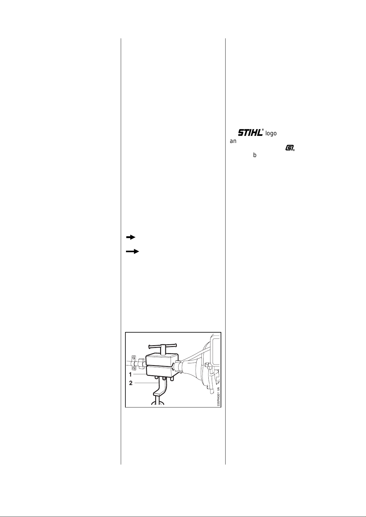
Securetheclamptotheassembly
standwithtwowashersandtwo
M8nuts.
Thecompletemachinecanthen
beswivelledtothebestposition
fortheongoingrepairandthisleavesbothhandsfree.
AlwaysuseoriginalSTIHL
replacementparts.
Theycanbeidentifiedbythe
STIHLpartnumber,
the
STIHL
andthe
STIHLpartssymbol
Thesymbolmayappearaloneon
smallparts.
logo
(
Afaultonthepowertoolmayhave
severalcauses.Apartfromthe
chapter"Troubleshooting"inthis
manual,alsoconsultthetroubleshootingchartsforallassembliesin
the"StandardRepairs,Troubleshooting"handbook.
Refertothe"TechnicalInformation"bulletinsforengineering
changeswhichhavebeenintroducedsincepublicationofthis
servicemanual.Technicalinformationbulletinsalsosupplementthe
partslistuntilarevisededitionis
issued.
2 FS25-4,65-4
Servicingandrepairsaremade
considerablyeasierifthemachine
ismountedonassemblystand(2)
59108903100withtheaidof
clamp(1)59108908800.
Page 3

3. Specifications
3.1 Engine
Singlecylinderfour-strokeoverheadvalveengine
FS25-4 FS65-4
Type: GX22 GX31
Displacement: 22cm
3
31cm
3
Bore: 33mm 39mm
Stroke: 26mm 26mm
PoweroutputtoISO8893: 0.6kW(0.8bhp) 0.85kW(1.2bhp)
at7,000rpm at7,000rpm
Max.enginespeed: Maximumrpmisdeterminedbymainjetandisnotadjustable
Idlespeed: 3,100±200rpm
Compressionpressure: 29-59kPa(2.9-5.9bar)
at1,200rpm
Pistonpindiameter: 8mm
Rewindstarter: Pawlengagement
Pawls: Singlepawlsystem
Reservepullonroperotor: min.1/2turn
Starterropediameter: 3mm
Clutch: Centrifugalclutchwithpress-fittedlinings
Clutchengagesat: 4,200±200rpm
Valveclearance
Inlet: 0.12±0.02mm
Exhaust: 0.15±0.02mm
Oilcapacity: 0.1l(100cm
3
)
Oilgrade: SAE15W-40
3.2 FuelSystem
Carburetor: Diaphragmcarburetor
Carburetorleakagetest
atgaugepressure: 8kPa(0.8bar)
Functionoftankvent
atgaugepressure: ≤3kPa(0.3bar)
undervacuum: ≤0.5kPa(0.05bar)
Fueltankcapacity: 0.45l(450cm
3
) 0.65l(650cm3)
Fuel: Regularbrandnamegasoline
Octanerating: min.90RON
Airfilter: Oilimpregnatedfoamfilter
FS25-4,65-4 3
Page 4

3.3 Ignition System Type: Electronic magneto
ignition (breakerless)
with integral trigger unit
Ignition timing: 27 degrees B.T.D.C.
Air gap: 0.35 - 0.5 mm
Spark plug (suppressed): NGK CR5HSB,
Denso U16FSR-UB
Electrode gap: 0.6 - 0.7 mm
3.4 Gearhead Type: Spiral-toothed bevel gear drive
Gear ratio: 1:1.4
Bearings: Deep groove ball bearings
Lubrication: STIHL gear lubricant
0781 120 1117, 1118
(capacity 7 g)
3.5 Special Accessories
3.5.1 For User Full harness
Safety glasses
Transport guard for
Metal cutting tools 4119 717 3005
STIHL gear lubricant (80 g tube) 0781 120 1109
STIHL gear lubricant (80 g tube) 0781 120 1117
4 FS 25-4, 65-4
Page 5

3.6 Dimen sionsandWear Limits
Description Standard Wear limit
Cylinder inside diameter 33.00 mm * 33.10 mm *
39.00 mm ** 39.10 mm **
Piston outside diameter 32.99 mm * 32.90 mm *
38.99 mm ** 38.90 mm **
Piston pin outside diameter 8.00 mm 7.95 mm
Cam lift 22.79 mm 22.49 mm
(inlet and exhaust)
Free length of valve springs 23.40 mm 22.50 mm
Valve stem outside diameter
Inlet: 3.985 mm 3.900 mm
Exhaust: 3.950 mm 3.880 mm
Valve guide inside diameter 4.000 mm 4.060 mm
Clearance between valve stem and guide
Inlet: 0.015 - 0.048 mm 0.098 mm
Exhaust: 0.050 - 0.083 mm 0.120 mm
Valve head diameter
Inlet: 12.5 mm *
13.5mm**
Exhaust: 12.0 mm
Clutch lining: 2.0 mm 1.0 mm
* FS 25-4
** FS 65-4
FS 25-4, 65-4 5
Page 6

3.7 Tightening Torques
DG and P screws (Plastoform) are used in polymer and lightmetal components. These screws form a
permanent thread when they are installed for the first time. They can be removed and installed as often
as necessary without detrimentally affecting the strength of the screwed assembly, providing the specified
tightening torque is observed. For this reason it is essential to use a torque wrench.
Fastener Thread For component Torque Remarks
size Nm
Pan head screw M5x12 Valve cover 4.0
Pan head screw M5x22 Valve cover 4.0
Nut M5 Valve adjusting screw 5.0
Collar nut M8 Flywheel 15.0
M8 Starter cup 8.0
Nut M5 Carburetor 5.0
Pan head screw M6x28 Clutch shoes 10.0 1)
Pan head screw M8x28 Clutch shoes 15.0 2)
Pan head screw M4x16 Cam gear cover 3.0
Pan head screw M5x18 Crankcase 5.0
Pan head screw M5x55 Crankcase cover
1st stage 3.0
2nd stage 7.0
Spline screw IS-DG5x24 Gear housing/drive tube 8.5
Spline screw IS-M5x12 Clamp, control handle/
drive tube (loop handle) 2.0
Spline screw IS-M5x16 AV sleeve/drive tube (clamp screw) 5.5
Spline screw IS-M5x12 Clamp, control handle/drive tube 2.0
Spline screw IS-M5x16 Clamp/drive tube (harness) 4.5
Spline screw IS-M5x30 Control handle (bike handle) 2.0
Spline screw IS-M6x25 Clamp/loop handle 4.5
Screw plug M11x10 Gearhead 8.5
Plastoform screw IS-P4x16 Control handle/handle moldings 1.0
Collar screw IS-P3.5x10.6 Detent spring/slide control
(bike handle) 1.1
Nut M12x1.5 L Cutting tool 25.0
Spline screw IS-M5x16 Deflector/gearhead 4.3
All other screws M3 1.0
and nuts M5 5.0
M6 9.0
Use the following procedure to fit a DG or P screw in an existing thread:
– Place the DG or P screw in the hole and rotate it counterclockwise until it drops down slightly.
– Tighten the screw clockwise to the specified torque.
This procedure ensures that the screw engages properly in the existing thread and does not form a new thread,
which would weaken the assembly.
1) FS 25-4
2) FS 65-4
Note: Power screwdriver speed settings for polymer: Plastoform screws max. 600 rpm
DG screws max. 500 rpm
6 FS 25-4, 65-4
Page 7
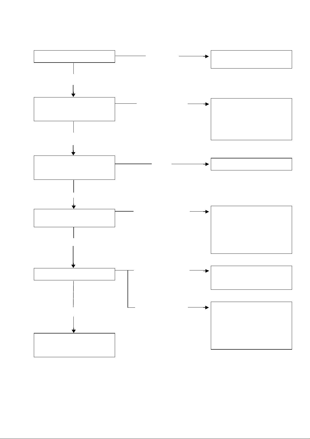
4. Troubleshooting
1. Engine difficult to start
Check fuel level in tank.
Adequate fuel in
tank
Operate manual fuel pump
and check that fuel is flowing to
carburetor.
Fuel flows to
carburetor
Remove spark plug and
check for damp or oily
electrodes.
Damp
No fuel
Fuel does not flow
to carburetor
Dry
Fill up with fuel and try starting
again.
– Check fuel line and fuel
filter for blockages.
– Faulty carburetor diaphragm
or float needle valve,
replace carburetor
Replace carburetor
Check spark plug
for spark.
Powerful spark
Check compression.
Adequate compression
Install spark plug and start
engine according to
instructions.
No spark or only a
weak spark
Compressioninorder
Compression too low
– Change spark plug and
repeat the spark test.
– Check ignition lead for
damaged insulation and
leakage current.
– Check ignition coil.
Check combustion chamber
for excessive build-up of
combustion deposits.
– Check, adjust valve
clearance.
– Valves must be in good
condition.
– Check piston, rings and
cylinder for wear.
FS 25-4, 65-4 7
Page 8
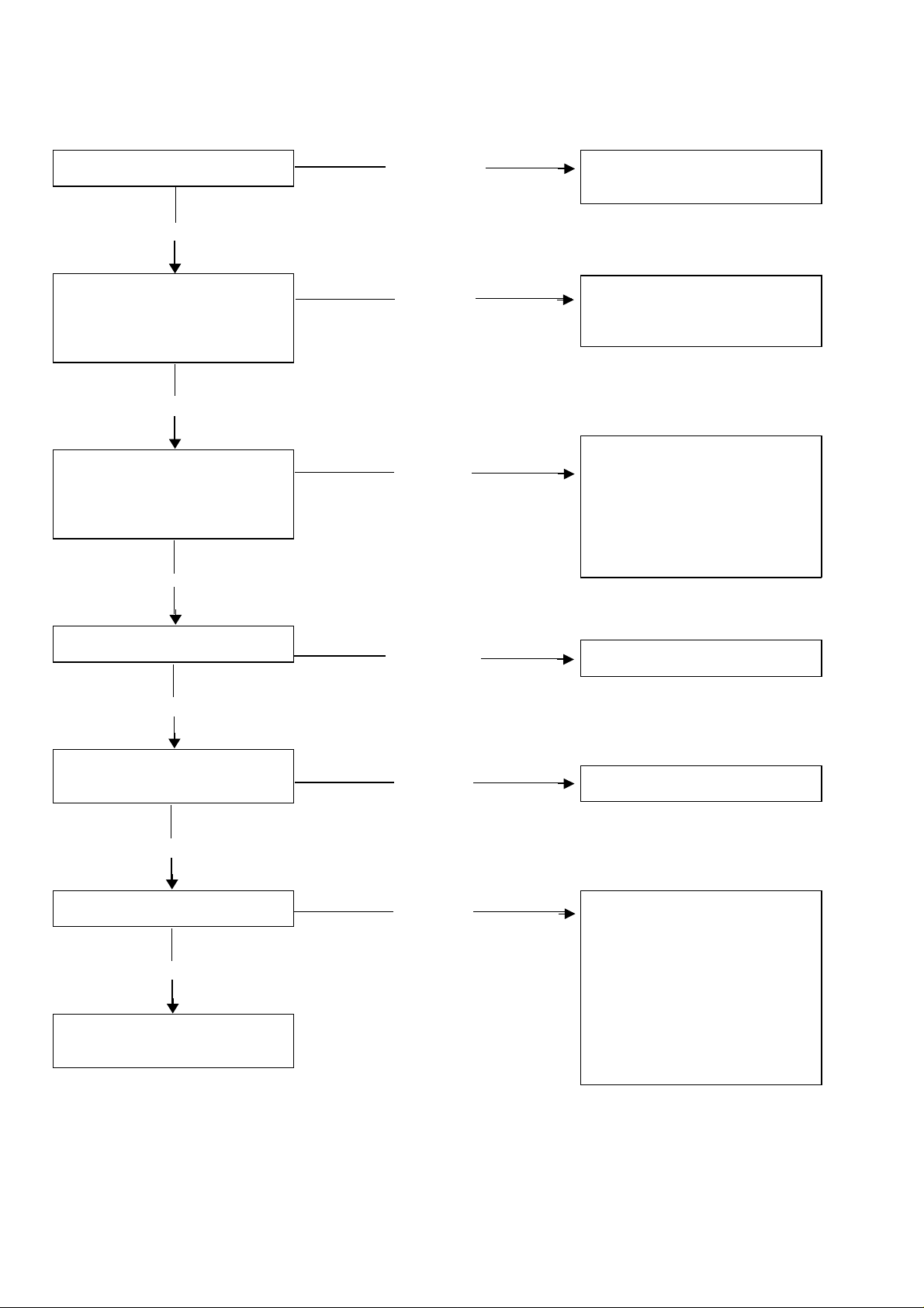
2. Erratic running behavior at low rpm
Inspect air filter element.
Not dirty
Remove spark plug and
check electrodes for coking,
check electrode gap.
Normal
Check to see if fuel line is kinked, pinched or cracked. Check
carburetor for looseness or air
entering through spacer flange.
Normal
Dirty
Abnormal
Abnormal
Clean, replace air filter
element.
– Clean spark plug and
adjust electrode gap.
– Replace spark plug.
– If fuel line is kinked
or pinched, fit a
new one.
– Tighten loose carburetor
nuts. Examine spacer
flange for damage and
install properly.
Check fuel filter.
Not dirty
Check correct function of
carburetor.
Normal
Check compression.
Normal
Start engine according to
instructions.
Dirty
Abnormal
Abnormal
Clean, replace filter.
Replace carburetor.
– Check, adjust valve
clearance.
– Check combustion chamber
for excessive build-up of
combustion deposits.
– Check valves for faults.
– Check piston, rings and
cylinder for wear.
8 FS 25-4, 65-4
Page 9
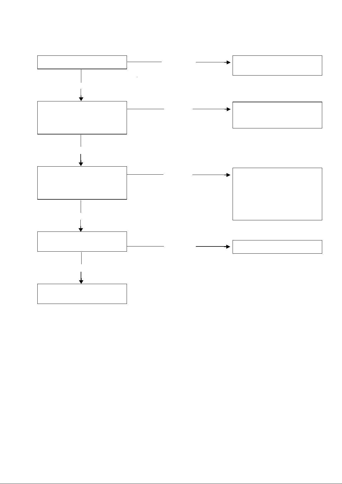
3. Erratic running behavior at high rpm
Inspect air filter element.
Not dirty
Remove spark plug and
check electrodes for coking,
check electrode gap.
Normal
Check to see if fuel line is kinked, pinched or cracked. Check
carburetor for looseness or air
entering through spacer flange.
Normal
Dirty
Abnormal
Abnormal
Clean, replace air filter
element.
– Clean spark plug and
adjust electrode gap.
– Replace spark plug.
– If fuel line is kinked
or pinched, fit a
new one.
– Tighten loose carburetor
nuts. Examine spacer
flange for damage and
install properly.
Check correct function of
carburetor.
Normal
Start engine according
to instructions.
Abnormal
Replace carburetor.
FS 25-4, 65-4 9
Page 10
5. Clutch
5.1 RemovingandDisassembling 5.2 AssemblingandInstalling
Important:Iftherearesignsof
seriouswearontheinside
diameter,fitanewclutchdrum-
see13.2.
Troubleshootingchart-see
"StandardRepairs,Troubleshooting"handbook.
-Removetheshroud-see6.1.
-Removecontrolhandlefrombike
handle-see12.1.
-Onloophandlemachine,dis-
connectthrottlecablefrom
carburetor-see9.5.1.
•
Takeoutthescrews.
-Pulloffclutchhousingwithdrive
tube.
-Blockpistonwithlockingscrew-
see7.2.
•
Takeoutthecollarscrews(1).
•
Removetheclutchshoes(2).
•
Attachspringtoclutchshoes.
•
Fitthewashers.
•
Inspectclutchdrum.There
shouldbenoscoresorsigns
ofexcessivewear.
10 FS25-4,65-4
•
Twisttheclutchshoesand
detachthespring.
Important:Clutchshoesmust
alwaysbereplacedinpairs.
•
Fitclutchshoessothatthe
marksfaceoutwards.
" "=FS25-4
"R"=FS65-4
Page 11
•
Insertcollarscrews.
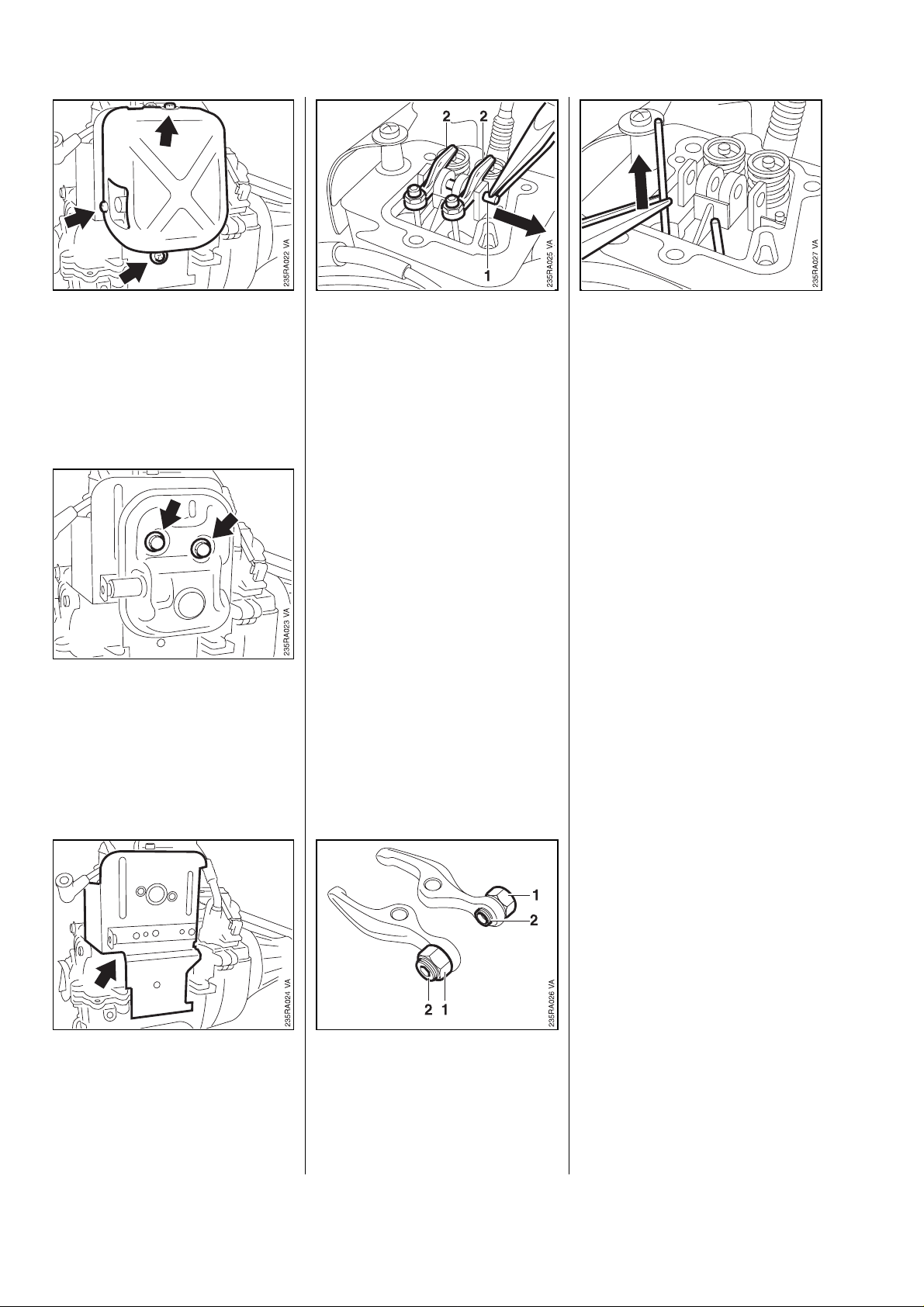
6. Engine 6.2 Checking/Adjusting
6.1 ValveClearance
Note:Checkandadjustvalveclea-
ranceonlywhenengineiscold.
-Removetherewindstarter.
-Removetheairfilter-see11.1.
•
Tightendowncollarscrewsto10
Nm(FS25-4)or15Nm(FS65-
4).
-Removelockingscrewfromcylinder.
-Installclutchhousingwithdrive
tube.
-Onloophandlemachine,attach
throttlecabletocarburetor.
-Onbikehandlemachine,install
thecontrolhandle.
-Fittheshroud.
-Pulloffthesparkplugboot.
•
Takeignitionleadoutofthe
retainer.
•
Slackenoffnut(1).
•
Pullthrottlecable(2)withshort
circuitwire(3)andwasher(4)
outofretainer.
FS25-4,65-4 11
Page 12
Note:Iftheexhaustvalveopens
whileyouareturningtheflywheel
toT.D.C.,rotateflywheelcounterclockwiseuntiltherecessand
projectionlineupagain.
•
Removeshroudfrombossesat
rewindstarterside.
•
Takeoutscrews(1)atclutch
side.
•
Removetheshroud(2).
•
Takeoutthescrews(1).
•
Removethevalvecover(2).
•
Removethegasket.
-Removeclutchhousingwithdrivetube-see12.4.
•
Insertfeelergauge(1)between
rockerarmandvalvestem.
Inletvalve(2):0.12±0.02mm
Exhaustvalve(3):0.15±0.02mm
Checking
•
Pullventhose(1)offthe
valvecover.
•
Pullignitionlead(2)andshort
circuitwire(3)outofthe
retainers.
12 FS25-4,65-4
•
Rotateflywheeluntilblade
recess(1)linesupwiththe
projection(2)onthecamgear
cover(pistonatT.D.C.).
Page 13
6.2 CheckingOilLevel/
ChangingOil
Adjusting
•
Slackenoffnut(1).Use2.5mm
Allenkeytorotateadjusting
screw(2).
Toincreasevalveclearance:
Turnscrewcounterclockwise.
Toreducevalveclearance:
Turnscrewclockwise.
-Holdadjustingscrewsteadyand
tightendownnutto5Nm.
Checking
-Putenginedownonalevel
surface.
-Unscrewthedipstickandwipeit
withacleancloth.
-Pushthedipstickintofillerneck
asfarasstopbutdonotscrewit
home.
-Putenginedownonalevel
surface.
-Fillupwithengineoiltoedgeof
fillerneck.
-Screwdipstickhomeandtighten
downfirmly.
-Checkvalveclearanceagain.
Assembleinthereversesequence.
-Usenewgasketforvalvecover.
-Tightendownvalvecover
screws
to4Nm.
•
Removethedipstickandcheck
theoillevel.
•
Ifoillevelislow,topupwith
freshengineoiltoedgeoffiller
neck.
-Screwdipstickhomeandtighten
downfirmly.
Changing
-Unscrewthedipstick.
-Tiptheenginetoonesideto
drainoilintoasuitablecontainer.
Note:Observesafetyprecautions-
see1.
FS25-4,65-4 13
Page 14
6.3 ExhaustMuffler 6.4 RockerArms/ Pushrod s
-Removetheshroud-see6.1.
•
Takeoutthescrews.
-Removetheguard.
•
Takeoutthescrews.
-Removethemuffler.
-Removethevalvecover-
see6.1.
-SetpistontoT.D.C.(bothrocker
armsrelieved).
•
Pulloutpin(1).
•
Removerockerarms(2).
•
Removethepushrods.
Assembleinthereverse
sequence.
-Pushrodsmustlocateproperly
intheadjustingscrews.
-Adjustvalves-see6.1.
•
Removecoverplate.
Assembleinthereverse
sequence.
Notedifferentlengthsofscrews.
14 FS25-4,65-4
•
Toreplace,slackenoffnut(1)
andtakeouttheadjusting
screw(2).
Page 15

6.5 CamFollowers 6.6 CamGear 6.7 Diaphragm
-Removethepushrods-see6.4.
-Removetheflywheel
-see7.2.
•
Takeoutthescrews.
-Removethecover.
•
Pulloutpin(1).
•
Removethecamfollowers(2).
Installinthereversesequence.
-Thoroughlycleanthesealing
faceonthecylinderandcover.
-Applythincoatingofsealantto
cylinder-see14.2.
-Removethecamfollowers
-see6.5.
•
Pulloutpin(1).
•
Removethecamgear(2).
-SetpistontoT.D.C.:
Slot(1)incrankshaftpointsup.
•
Installcamgearsothatmarks
(2)lineupandthemarked
tooth(3)isinalignmentwith
theslotinthecrankshaft.
Important:Themarksmustnot
moveoutofpositionwhilecam
gearisbeingfitted.
-Drainengineoil-see6.2.
-Removethefueltank
-see11.6.
•
Takeoutthescrews.
-Removethecover.
•
Takeoutscrew(1).
•
Removethesupportplate(2).
•
Important:Followmanufacturer’s
instructions.
-Tightendownscrewsoncover
to3Nm.
-Installtheflywheel-see7.2.
-Installthepushrods
-see6.4.
FS25-4,65-4 15
Installthecamfollowers
-see6.5.
•
Removethediaphragm.
Page 16

6.8 Crankcase,
LowerHalf
•
Theangledcorneronthe
diaphragmandsupportplate
mustlineupwiththeanglein
thecrankcase(seearrows).
-Thoroughlycleanthesealingfacesonthecrankcaseandcover.
-Applythincoatingofsealantto
sealingfaceoncrankcase-
see14.2.
Important:Followmanufacturer’s
instructions.
-Fitthecover.
-Coatscrewthreadsandflanges
withengineoilandinsertscrews.
-Removecoveroverdiaphragm-
see6.7.
•
Takeoutthescrews.
-Takeawaythelowerhalfofthe
crankcase.
•
Unscrewdipstickifnecessary.
•
Checktoseeifoilreturnbores
areblocked.Blowclearwith
compressedairifnecessary.
-Thoroughlycleansealingfaces
onbothhalvesofcrankcase.
-Applythincoatingofsealantto
lowerhalfofcrankcase-
see14.2.
Important:Followmanufacturer’s
instructions.
-Tightendownscrewsto5Nm.
-Installcoveroverthediaphragm-
see6.7.
•
Initiallytightenscrewsin
sequenceshown(1to4)to
3Nm,thenfinallytightento
7Nminsamesequence.
16 FS25-4,65-4
•
Removegrommetsifnecessary.
Page 17

6.9 Crankshaft
-Removecamgearcover-
see6.5.
-Removethefanwheel-see8.6.
-Removelowerhalfofcrankcase
-see6.8.
-Ifoneofthesepartsisdamaged,
thecompletecrankshaftmustbe
replaced.
•
Rotatecamgearsothatthe
marks(1)areinalignment.
-Carefullypushthepistonintothe
cylinder.
Note:Thepistonringsandtheoil
scraperringarecompressedas
theyareeasedintothetapered
cylinder.
•
Turnthecrankshaftsothatthe
slot(2)pointstowardsthecam
gear.
•
Liftcrankshaftandpullpistonout
ofcylinderatthesametime.
-Inspectcylinderrunningface,
replacecylinderifnecessary-
see6.11.
•
Beforeinstallingthecrankshaft,
checkoilwayforblockages
andblowclearwithcompressed
airifnecessary.
-Coatpiston,pistonringsandoil
scraperringwithoil.
-Fitpistonringsothattheirgaps
areoffset120degrees.
Important:Ringgapsmustnotbe
inlinewithpistonpinbore.
•
Continuepushingpistoninto
cylinderandmakesurethatthe
markedtooth(3)linesupwith
theslot.
-Fitnewoilsealswiththeopen
sidefacingthecrankshaftand
pushcrankshaftfullyhome.
•
Removetheoilseals(1).
Note:Annularrib(1)mustengage
•
Inspectthepiston(2),ball
bearing(3)andoilsplash
plate(4).
FS25-4,65-4 17
groove(2).
Assembleallotherpartsin
thereversesequence.
Page 18

6.10 Valves/ValveSprings 6.11 Crankcasewith
Cylinder
-Removerockerarm/pushrods
-see6.4.
-Removethecrankshaft-see6.9.
•
Inspectseatsonexhaustvalve
(1),inletvalve(2)andcylinder
andreplacepartsasnecessary.
•
Checkfreelengthofvalve
springs(3),replacespringsifnecessary.
Assembleinthereverse
sequence.
Important:Donotmixupinlet
andexhaustvalves.
-Removethevalves-see6.10.
-Removethecamgear
-see6.6.
-Removethemuffler-see6.3.
-Removethecarburetor-
see11.2.2.
•
Pressvalvespringretainer(1)
downandmoveitsidewaysso
thatthevalvestemisinthelarge
hole.
•
Letgoofvalvespringretainer
andremoveittogetherwiththe
valvespring(2).
-Takevalvesoutofcylinder.
-Valvespringretainermust
engageproperlyingrooveon
valvestem.
•
Takeoutthescrews(1).
•
Removetheheatshield(2)and
spacerflange(3).
•
Takescrewsoutofspacerflange.
18 FS25-4,65-4
Page 19

7. Ignition System 7.1 Ignition Module
Warning! Exercise extreme
caution when carrying out
maintenance and repair work on
the ignition system. The high
voltages which occur can cause
serious or even fatal accidents!
Troubleshooting on the ignition system should always begin at
the spark plug. See "Standard Repairs, Troubleshooting" handbook.
•
Remove the gasket.
Assemble in the reverse
sequence.
- Use a new gasket.
•
Install spacer flange so that
recess (1) points down.
•
Secure connector tag (2) for
short circuit wire with the upper
screw.
Note: The electronic (breakerless)
ignition system basically consists
of an ignition module (1) and
flywheel (2).
The ignition module accommodates all the components required to
control ignition timing.
There are two electrical connections on the coil body:
1. the high voltage output with
ignition lead (1)
2. the connector tag (2) for the
short circuit wire
Accurate testing of the ignition
module is only possible with
sophisticated test equipment. For
this reason it is only necessary to
carry out a spark test in the workshop. A new ignition module must
be installed if no ignition spark is
obtained (after checking that
wiring and stop switch are in good
condition).
FS 25-4, 65-4 19
Page 20

7.1.1 IgnitionTiming 7.1.2 RemovingandInstalling
Ignitiontimingisnotadjustable.
Sincethereisnomechanicalwear
inthesesystems,ignitiontiming
cannotgetoutofadjustment.However,aninternalfaultinthecircuit
canaltertheswitchingpointin
suchawaythatasparktestwill
stillshowthesystemtobeinorder
althoughtimingisoutsidethe
permissibletolerance.Thiswill
impairenginestartingandrunning
behavior. -Removetheshroud-see6.1.
•
Takeoutthescrews.
-Removetheclutchhousingwith
drivetube-see12.4.
•
Disconnectshortcircuitwire
fromignitionmodule.
-Removetheignitionmodule.
•
Slipfeelergauge(0.4mm)
betweenthearmsoftheignition
moduleandtheflywheelmagnet
poles.
-Presstheignitionmodule
againstthefeelergaugeand
tightendownthemounting
screws.
Reassembleallotherpartsinthe
reversesequence.
•
Removeignitionleadfromthe
retainers.
20 FS25-4,65-4
Page 21

7.2 Flywheel
1
•
Usestrapwrenchtohold
flywheelsteadyandpullitoff.
VA
235RA138
Removingtheflywheel:
-Removetheclutch-see5.1.
•
Screwlockingscrew(1)4170
8931200intocylinderasfaras
stop.
•
Unscrewtheflywheelnut.
Inspecttheflywheel(1)and
magnetpoles(2)forcracksorotherdamage.Ifyoufindany
damage,installanewflywheel.
•
Checkcorrectpositionofkey.
•
Fitflywheelinposition,screw
onthenutandtightenitdown
to15Nm.
-Removelockingscrewfromcylinder.
Installingtheflywheel:
-Fitandtightendownthespark
plug.
Important:Cleanthestubofthe
crankshaftandtheflywheelhub
-Installtheclutch-see5.2.
borewithastandardcommercial,
solvent-baseddegreasantwhich
containsnochlorinatedor
halogenatedhydrocarbons
-see14.2.
•
Attachpuller(1)41198904501
toflywheelwithM6x25or
M8x25screws(2).
FS25-4,65-4 21
Page 22

8. RewindStarter
8.1 General 8.2 RopeRotor
Iftheactionofthestarterrope
becomesverystiffandtherope
rewindsveryslowlyornotcompletely,itcanbeassumedthat
thestartermechanismisinorder
butpluggedwithdirt.Atverylow
outsidetemperaturesthelubricatingoilontherewindspringmay
thickenandcausethespring
windingstosticktogether.This
hasadetrimentaleffectonthe
functionofthestartermechanism.
Insuchacaseitissufficientto
applyafewdropsofparaffin
(kerosine)totherewindspring.
Thencarefullypulloutthestarter
ropeseveraltimesandallowitto
rewinduntilitsnormalsmooth
actionisrestored.
Ifcloggedwithdirtorpitch,the
entirestartermechanism,includingtherewindspring,mustberemovedanddisassembled.Take
specialcarewhenremovingthe
spring.
Troubleshootingchart-see
"StandardRepairs,Troubleshooting"handbook.
-Removerewindstarterandtake
offthemachinesupport.
Relievetensionofrewindspring:
Note:Therewindspringwillnot
beundertensionifthestarterrope
isbroken.
-Pulloutthestarterropeabout
20cmandholdtheroperotor
steady.
•
Carefullypulltheroperotor(4)
offthestarterpost.
Caution:Therewindspringishousedintheroperotor.Itmaypop
outiftheroperotorispulledout
tooquickly.
-Removetherewindspring-
see8.5.1.
-Removestarterrope-see8.3.
-Lubricateboreinroperotorwith
STIHLspeciallubricant-
see14.2.
Washallpartsinparaffinorwhite
spirit.
Lubricatetherewindspringand
starterpostwithSTIHLspecial
lubricant,see14.2,before
installing.
-Locatestarterropeinthenotch
intheroperotor.
•
Usestarterropetoturnrotor
clockwiseuntilspringisnolongerundertension.
•
Fitroperotoronthestarterpost
sothattheinnerspringloop(1)
engagesthegroove(2)inthe
starterpost.
-Fitthecarrierwithspringsothat
thespringengagestheslotin
theroperotor.
Important:Donotturntherope
rotorclockwise.
-Insertscrewandtightenitdown
firmly.
-Tensiontherewindspring-
see8.5.2.
•
Takeoutscrew(1).
•
Removecarrier(2)with
spring(3).
22 FS25-4,65-4
Page 23

8.3 StarterRope 8.4 StarterGrip
-Removetherewindstarter.
-Pullstarterropeoutalittleand
holdtheroperotorsteady.
VA
362RA095
-Removetheroperotor-see8.2.
-Removethestartergrip-see8.4.
-Takeremainingropeoutofthe
roperotor.
•
Threadnewstarterropethrough
theholeinthesideoftherope
rotorandsecurewithoneofthe
specialknotsshown.
•
Pulltheropebacksothatthe
knotlocatesintherecessinthe
roperotor.
-Installtheroperotor-see8.2.
Standardgrip:
-Pullropeoutofstartergrip,untie
theknotandslipthegripoffthe
rope.
-Threadstarterropethroughthe
newgrip.
ElastoStart:
•
Prycapoutofstartergrip.
-Pullropeoutofstartergrip.
•
Threadendofnewstarterrope
throughtheundersideofthestartergrip.
-Secureendofropewithasimple
overhandknot.
VA
362RA096
•
Secureendofropewithoneof
thespecialknotsshown.
-Pullstarterropebacksothat
theknotissnuglyseatedinthe
startergrip.
•
Pulltheropebacktolocatethe
knotinthestartergrip.
-Pushcapintostartergrip.
FS25-4,65-4 23
VA
362RA097
Page 24

8.5 RewindSpring
8.5.1 Replacing 8.5.2 Tensioning
-Holdthestartergripfirmlyto
keeptheropetensioned.
-Letgooftheroperotorand
slowlyreleasethestarterrope
sothatitcanrewindproperly.
-Removetheroperotor-see8.2.
-Takeremainingpiecesofrewind
springoutofroperotorandstartercover.
•
Engagetheouterspringloopin
therecessandfittherewind
springcounterclockwiseinthe
roperotor,startingoutsideand
workinginwards.
-Lubricatedspringwithafew
dropsofSTIHLspeciallubricant-
see14.2.
-Installtheroperotor-see8.2.
-Tensiontherewindspring-
see8.5.2.
•
Locatestarterropeinnotchin
theroperotorandmakealoop.
•
Griptheropeclosetotherotor
anduseittoturntheroperotor
fivefullturnscounterclockwise.
Note:Therewindspringiscorrectlytensionedwhenthestartergrip
sitsfirmlyintheropeguidebush
withoutdroopingtooneside.If
thisisnotthecase,tensionthe
springbyoneadditionalturn.
Whenthestarterropeisfully
extended,itmuststillbepossible
torotatetheroperotoratleast
anotherhalfturnbeforemaximum
springtensionisreached.Ifthisis
notthecase,pulltheropeout,
holdtheroperotorsteadyand
takeoffoneturnoftherope.
Donotovertensiontherewind
springasthiswillcauseittobreak.
-Fitthesupportplate-see11.6.
•
Holdtheroperotorsteady.
•
Pullouttheropewiththestarter
gripandstraightenitout.
24 FS25-4,65-4
-Installtherewindstarter.
Page 25

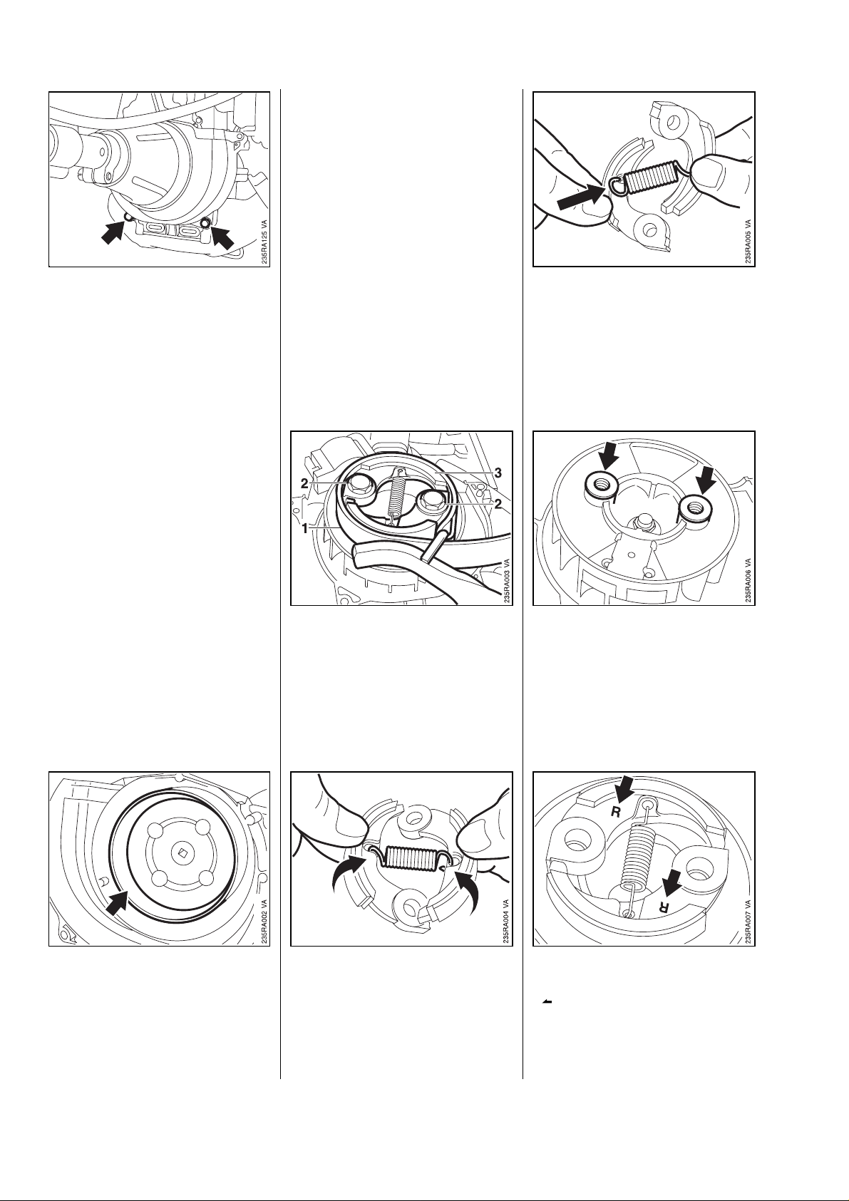
8.6 StarterCup/Fanwheel
•
Slipascrewdriverbetweenthe
punchesandunscrewthestarter
cup.
-Removetherewindstarter.
-Removetheclutch-see5.1.
•
Fitclutchmountingscrews
intappedholesinflywheel.
•
Usescrewdrivertoblock
flywheelasshown.
•
Removefanwheelfromstubof
crankshaft.
Assembleinthereverse
sequence.
•
Tightendownstartercupto
8Nmviaflywheelnut.
•
Insertpunchinboresinstarter
cupandholdsteady.
FS25-4,65-4 25
•
Blockstartercupwithpunches
andscrewdriver.
Page 26

9. Throttle Control
9.1 Throttle Trigger/Interlock Lever (Bike Handle)
•
Take out screw and washer.
- Pull off the control handle.
Warning: To avoid risk of electric
shock, do not start the unit while
the control handle is open.
•
Remove screws with screwdriver
(1) 5910 890 2301.
•
Remove the torsion spring.
•
Take the throttle trigger (1) with
torsion spring (2) and throttle
cable (3) off the peg.
•
Attach the throttle cable, then
position torsion spring as shown
and push its long arm into the
slot.
•
The interlock lever must be
behind the throttle trigger.
- Separate two halves of handle.
•
Lift the interlock lever (1) slightly
and turn it to one side until the
torsion spring (2) is relaxed.
•
Pull the interlock lever off the
peg.
26 FS 25-4, 65-4
•
Disconnect throttle cable from
trigger.
Assemble in the reverse
sequence.
•
Check correct positions of
throttle cable (1), contact spring
(2), protective tube (3) and
insulator(4).
Page 27

9.2 ContactSprings/DetentSpringinControlHandle 9.3 ThrottleTrigger/Interlock
(BikeHandle) Lever(LoopHandle)
-Removethethrottletrigger
-see9.1.
•
Liftcontactspring(1)alittleand
removethethrottlecable(2).
•
Removespringfromseats(1)
andpeg(2).
•
Takeoutslidecontrol’scollar
screw(1).
•
Removedetentspring(2).
•
Pullslidecontroloutofhandle
molding.
Assembleinthereverse
sequence.
-Engagecontactspringcorrectly
ingrooveofcollarscrew.
•
Usescrewdriver(1)
59108902301toremovescrew.
•
Pushguard(2)forward.
Warning:Toavoidriskofelectric
shock,donotstarttheunitwhile
thecontrolhandleisopen.
•
Removescrewswithscrewdriver
(1)59108902301.
-Removehandlemolding.
•
Removecontactspringfrom
peg(1)andcollarscrew(2).
FS25-4,65-4 27
•
Removetorsionspring.
Page 28

9.4 SlideControl
(LoopHandle)
•
Pullthrottletrigger(1)with
throttlecable(2)offthepeg.
•
Disconnectthrottlecablefrom
trigger.
•
Pullinterlockleverwithcontact
springoffthepeg.
•
Removecontactspringfrom
interlocklever.
Assembleinthereverse
sequence.
-Removetheinterlocklever
-see9.3.
•
Pullslidecontroloffthehandle
molding.
•
Removescrewsfromclamps.
-Takehandlemoldingoffthedri-
vetube.
•
Liftcontactspring(1)alittleand
removethethrottlecable(2).
28 FS25-4,65-4
•
Checkpositionsofthrottlecable
(1),contactspring(2),protective
tube(3)andinsulator(4).
-Tightenscrewsto1.0Nm.
•
Removetorsionspringfrompeg.
Page 29

9.5 ThrottleCable
9.5.1 Replacing
-Removetheairfilter-see11.1.
-Takethrottlecableoffthecontactspring-see9.2.
Assembleinthereverse
sequence.
-Tightenclampscrewsto2.0Nm
•
Thegroove(1)intheslide
controlmustengageovertheouteredge(2)ofthehandlemolding.
•
Thetorsionspring(3)must
engagetherecess(4)intheslidecontrol.
•
Pullshortcircuitwireoffthe
connectortag.
•
Slackenoffnut(1).
•
Pullthrottlecable(2)outofholder.
•
Removeshortcircuitwire(3)
fromthethrottlecable.
•
Onbikehandle,takethrottle
cableoutofretainers.
Assembleinthereverse
sequence.
-Adjustthrottlecable-see9.5.2.
•
Disconnectthrottlecablenipple
(1)fromslottedpin(2)onthrottle
lever.
FS25-4,65-4 29
Page 30

9.5.2 Adjusting 10. AVSystem
Throttlelever(1)mustbuttagainst
housing(2)whenthrottletriggeris
squeezed(fullthrottle)andagainst
theidlespeedscrewwhenthe
triggerisintheidleposition.
Adjustmentiseffectedbymoving
thethrottlecableintheholder.
-Removetheairfilter-see11.1.
Rotatesleeveclockwiseto
moveleverclosertohousing.
Rotatesleevecounterclockwiseto
moveleverawayfromhousing.
-Lockadjustingsleevewithnut
(1)aftercompletingadjustment.
-Installtheairfilter-see11.1.
Theanti-vibration(AV)connection
betweentheengineanddrivetube
consistsofarubberelement
installedintheclutchhousing.
-Removethedrivetube
-see12.4.
-Removetheshroud-see6.1.
•
Slackenoffnut(1).
•
Rotateadjustingsleeve(2)as
required.
•
Takeoutthescrews.
-Removetheclutchhousing.
•
Usepliers(1)08116418380to
removeretainingringfromclutch
housing.
-Removeretainingringover
theAVsleeve.
30 FS25-4,65-4
Page 31

•
Push installing tool (1)
4126 893 4900 into AV sleeve
as far as stop.
•
Tighten down clamp screw (2).
•
Tighten the fixing screw (3)
moderately if necessary.
•
Release clamp screw (1) and
fixing screw (2) if necessary.
•
Pull the AV sleeve (3) off the
installing tool.
- Coat rubber element with a
lubricant (e.g. washing-up liquid).
•
Push the rubber element into
clutch housing as far as stop
so that slot (1) is opposite the
straight side (2) of the clutch housing.
- Apply a little lubricant (e.g.
washing-up liquid) between
the clutch housing and rubber
element.
•
Pull the rubber element off the
AV sleeve.
Assemble all other parts in the
reverse sequence.
- Retaining ring must locate
properly in the groove in the
clutch housing.
•
- Clamp installing tool in vice.
•
Pull clutch housing off the
rubber element.
FS 25-4, 65-4 31
Push the rubber element, larger
diameter (1) first, onto the AV
sleeve until the inner groove (2)
engages the annular rib (3).
Page 32

11. FuelSystem 11.2 Carburetor
11.1 AirFilter 11.2.1 LeakageTest
Dirtyandcloggedairfiltersreduce
enginepower,increasefuel
consumptionandmakestarting
moredifficult.
Theairfiltermustbecleaned
whenthereisanoticeableloss
ofenginepower.
-Closethechokeshutter.
-Cleanawayanyloosedirtfrom
aroundthefilterandfiltercover.
Washthefoamfilterinaclean,
non-flammablesolution(e.g.warm
soapywater)anddry.
Note:Replaceadamagedfoam
filterimmediately.
-Soakfoamfilterinfreshengine
oilandthensqueezeoutsurplus
oil.
-Installfoamfilter.
Troubleshootingchart-see
"StandardRepairs,Troubleshooting"handbook.
Important:Intheeventoftrouble
withthecarburetororthefuel
supplysystem,alwayscheckand
cleanthetankvent-see11.3.
Thecarburetorcanbetestedfor
leakswiththecarburetorand
crankcasetester11068502905.
-Removetheairfilter-see11.1.
•
Pressdownthetab.
•
Swingthefiltercoverdownwards
andliftitaway.
•
Removethefoamfilter.
•
Engagelugsonfiltercoverin
filterhousing.
-Swingfiltercoverupsothatit
snapsintoposition.
•
Pullfuelhoseoffcarburetor’s
elbowconnector.
2 1
•
Fitfuelhose(1)11101418600
onnipple(2)00008559200.
VA
143RA172
32 FS25-4,65-4
Page 33

•
Pushthefuelhosewithnipple
ontothecarburetorelbow
connector.
Ifthispressureremainsconstant,
thecarburetorisairtight.However,
ifitdrops,therearetwopossible
causes:
1.Theinletneedleisnotsealing
(foreignmatterinvalveseator
sealingconeofinletneedleis
damagedorinletcontrollever
sticking).
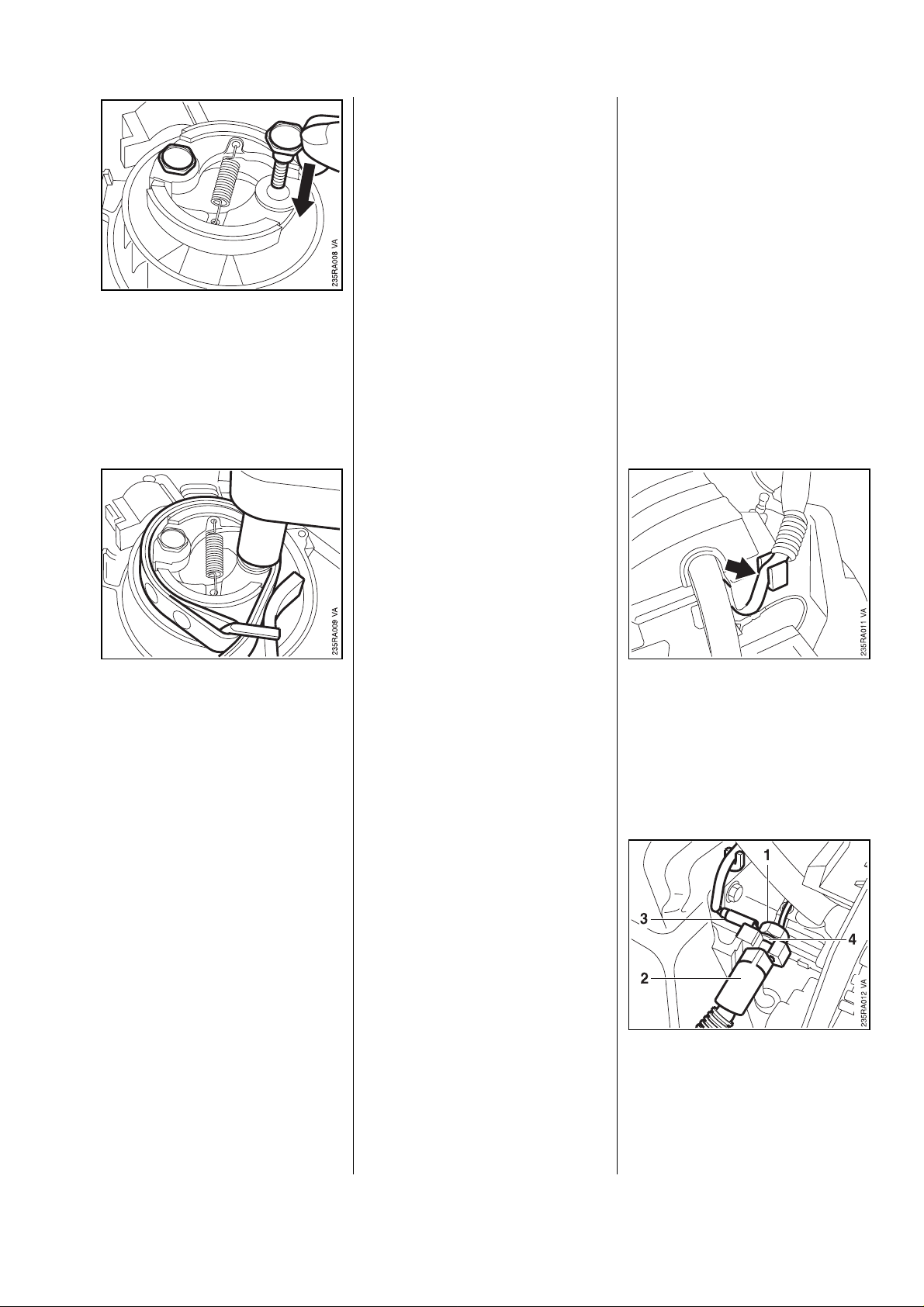
2.Themeteringdiaphragmis
damaged.
-Aftercompletingtest,openthe
ventscrewandpullthefuelhose
offtheelbowconnector.
-Pushthefuelhoseontothe
elbowconnector.
-Installtheairfilter-see11.1.
11.2.2 RemovingandInstalling
-Removetheairfilter-see11.1.
•
Pullbothfuelhosesofftheelbow
connectors.
•
Pushthenippleintothetester’s
pressurehose.
•
Closetheventscrew(1)onthe
rubberbulb(2)andpumpairinto
thecarburetoruntilthepressure
gauge(3)showsareadingof
approx.8kPa(0.8bar).
•
Disconnectthrottlecablenipple
(1)fromslottedpin(2)onthrottle
lever.
•
Pullventhoseoffthefilter
housing.
FS25-4,65-4 33
Page 34

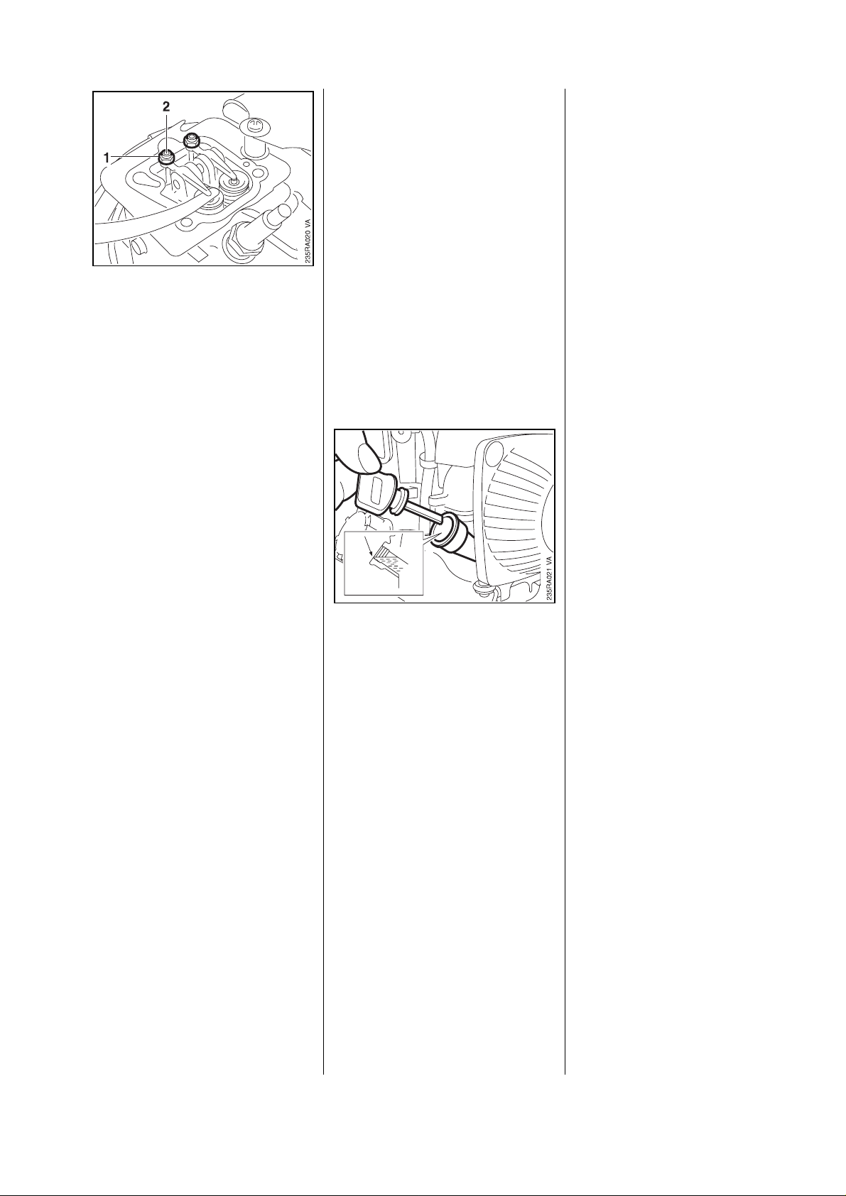
11.2.3 AdjustingIdle
Speed
•
Unscrewnuts(1).
•
Removethesupportplate(2).
•
Pullthefilterhousing(3)away.
•
Takethesealingringoffthe
carburetor.
•
Removethegasket.
-Inspectspacerflangeand
replaceifnecessary-see6.11.
Assembleinthereversesequence.
-Installnewgasketandsealing
ring.
-Tightendownnutsto5.0Nm.
-Checktheairfilter,replaceif
necessary.
-Starttheengineandallowitto
warmup.
•
Adjustengineidlespeedwiththe
idlespeedscrew.
Turnclockwisetoincreaserpm.
Turncounterclockwiseto
reducerpm.
Note:Ifyouuseatachometer,
notethatthereisanignitionspark
oneachcrankshaftrevolution.
•
Pullcarburetoroffthestuds.
34 FS25-4,65-4
Page 35

11.3 Tank Vent 11.4 Pickup Body
Correct operation of the carburetor
is only possible if atmospheric
pressure and internal fuel tank
pressure are equal at all times.
This is ensured by the tank vent.
Important: If problems occur on
the carburetor or the fuel supply
system, always check and clean
the tank vent.
Check function by performing
pressure and vacuum tests on
the tank via the fuel hose.
Cleaning
- Unscrew the filler cap.
•
Ease the cap (1) off the valve
body (2).
•
Take the cap (3) out of the valve
body.
•
Remove sealing ring (4) from the
valve body.
- If the sealing ring is damaged, fit
a new fuel filler cap (5).
•
Wash valve body and valve (6)
in fresh gasoline.
The diaphragm pump draws fuel
out of the tank and into the
carburetor via the fuel hose. Any
impurities mixed with the fuel are
retained by the pickup body (filter).
The fine pores of the filter eventually become clogged with minute
particles of dirt. This restricts the
passage of fuel and results in fuel
starvation.
Important: In the event of trouble
with the fuel supply system,
always check the fuel tank and
the pickup body first. Clean the
fuel tank if necessary.
Cleaning the fuel tank
- Unscrew the filler cap and drain
the tank.
- Pour a small amount of clean
gasoline into the tank.
- Close the tank and shake the
unit vigorously.
- Open the tank again and drain it.
Equalization of pressure from the
outside inwards takes place via
the thread in the filler cap, the valve and holes in the cap.
Equalization of pressure from the
inside outwards takes place via
the holes in the cap, the slots in
the valve body and thread in the filler cap.
- If the valve is damaged, fit a new
fuel filler cap.
•
Insert cap (3) in the valve body.
•
Slip sealing ring (4) over the valve body.
•
Fit cap (1) on valve body and
push it home until it snaps into
position.
- Screw on the fuel filler cap.
Note: Dispose of fuel properly.
Pickup body
- Unscrew the filler cap and
remove it together with the
retainer.
FS 25-4, 65-4 35
Page 36

11.5 FuelHoses
•
Usehook(1)59108938800to
pullthepickupbodyoutofthe
fueltank.
•
Squeezeendsofhoseclip(1)
togetherandpushitdownthe
hose.
•
Pullthepickupbody(2)offthe
fuelhose.
-Pullfuelhosesoffthe
carburetor-see11.2.2.
•
Takefuelhosesoutof
theretainer.
•
Easethegrommetoutofthe
fueltank.
•
Squeezeendsofhoseclip(1)
togetherandpushitdownthe
hose.
•
Pullthepickupbody(2)offthe
fuelhose.
•
Pullthefuelhosesoutofthe
grommet.
Installinthereversesequence.
-Fitnewpickupbody.
Installinthereversesequence.
•
Pulloutfuelhoseswithpickup
body.
36 FS25-4,65-4
•
Pullfuelhosesintothe
grommetsothatthedistance
"a"is113-121mm,and
"b"is125-135mm.
Page 37

11.6 FuelTank
-Drainthefueltank.
-Pullfuelhosesoffthecarburetor,
see11.2.2,andoutofretainer.
-Removetherewindstarter.
-Removethetankguard.
•
Removethesupportplate.
•
Easethegrommet(1)outofthe
fueltank.
-Pulloutfuelhoseswithpickup
body.
•
Unscrewfillercap(2)with
removetogetherwithcap
retainer.
Assembleinthereverse
sequence.
•
Positionfueltanksothatthelugs
(1)engagethegrommets(2).
•
Inspectgrommetinsupportplate
andfitnewgrommetifnecessary
withthewiderflangefacingthe
fueltank.
•
Removethefueltank.
FS25-4,65-4 37
•
Inspectgrommetsincrankcase
andfitnewonesifnecessary.
Page 38

12. Shaft
12.1 Bike Handle 12.2 Loop Handle
- To replace left grip, carefully cut
it open and pull it off.
- Coat inside of new grip with a
little lubricant (e.g. washing-up
liquid).
Note: If too much lubricant is
used, the grip will twist on the
tube. Always leave it to dry for a
while after fitting.
•
Take out the screw.
Loop handle without barrier bar
- Pull off the control handle.
•
Unscrew the nuts (1).
•
Remove lower clamp (2),
support block (3), bike handle (4)
and upper clamp (5) with screws
(6).
•
Pushthegripintopositionso
that the longer ends (see arrows)
point toward the gearhead at an
angle of 7 - 15 degrees to the
shaft.
Assemble all parts in the reverse
sequence.
•
Unscrew the nuts (1).
•
Remove lower clamp (2).
•
Remove screws (1).
•
Remove the loop handle (2) and
upper clamp (3).
Reassemble in the reverse
sequence.
•
Use jaws (1) 5910 893 2700 to
clamp bike handle tube in vice.
38 FS 25-4, 65-4
•
Align the loop handle at
distance"A"=20cmfromthe
control handle and tighten down
firmly.
Page 39

12.3 DriveShaft/
FlexibleLiner
Thedriveshaftissupportedina
flexiblelinerinsidethedrivetube.
Theendsofthedrivetubearesealedwithplugs.
-Removethegearhead-see13.1.
A
VA
398RA179
Loophandlewithbarrierbar
•
Takeoutthescrews(1).
•
Removelowerclamp(2).
•
Removethebarrierbar(1),loop
handle(2)andupperclamp(3).
•
Takethesquarenuts(4)outof
thebarrierbar.
Driveshaft
•
Pullthedriveshaftoutofthe
drivetube.
Note:Iftheshafthasturnedblue,
fitanewone.
•
Pushthedriveshaftintothedrivetubeuntildimension"A"is23
mm.Ifnecessary,applyslight
pressuretotheshaftandrotateit
slowlyuntilitcanbepushedinto
thespecifieddimension.
-Fitthegearhead-see13.1.
Reassembleinthereverse
sequence.
-CoatthedriveshaftwithSTIHL
gearlubricant07811201109,
Flexibleliner
see14.2,beforeinstallation.
Important:Applythegrease
uniformlyandthinlytothewhole
driveshaft.Donotpumpgrease
directlyintothedrivetube.
-Pushthedriveshaftintothedri-
vetube.
•
Aligntheloophandleat
distance"A"=20cmfromthe
-Removethedrivetube
-see12.4.
controlhandleandtightendown
•
firmly.
Prytheplugoutofthedrivetube.
FS25-4,65-4 39
Page 40

12.4 DriveTube
-Removethedriveshaft
-see12.3.
-Removethebikeorloophandle
-see12.1or12.2.
•
Pullouttheflexibleliner.
•
Thehole(1)mustbebetween
thespokes(2).
-Insertplug,installthedrivetube
-see12.4.
•
Onmachineswithbikehandle,
takethrottlecableoutof
retainers.
•
Takethefixingscrew(1)outof
theAVsleeve.
•
Releasetheclampscrew(2).
-Pulloutthedrivetube.
•
Onmachineswithloophandle,
pullthedrivetube(1)outofthe
controlhandle(2)atthesame
time.
•
Onmachineswithloophandle,
releasescrewsoncontrolhandle
clamps.
40 FS25-4,65-4
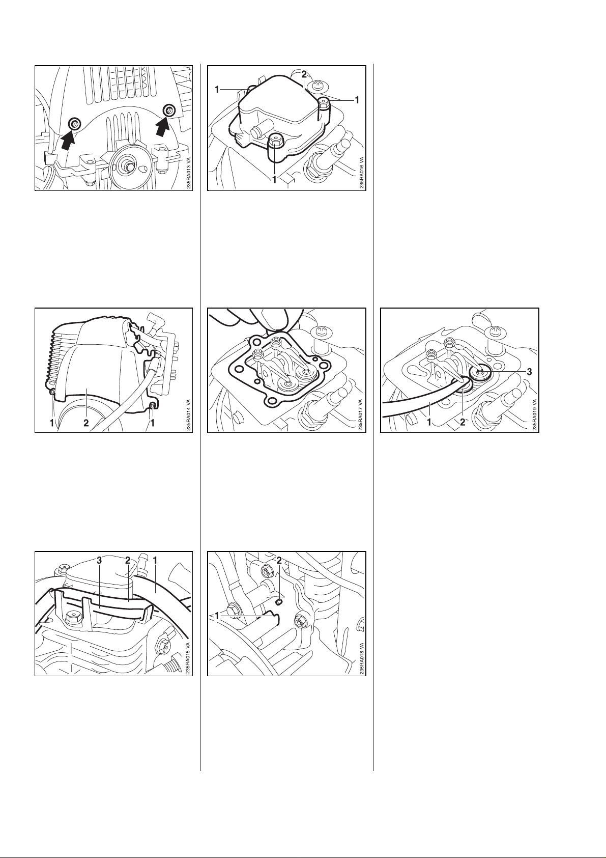
•
Slipthethrottlecableretainer,if
fitted,offthedrivetube.
Page 41

13. CuttingToolDrive
13.1 Gearhead 13.2 ClutchDrum
-Takerubberelement(AV
system)outofclutchhousing
-see10.
•
Removescrewfromhoseclamp
forharness.
•
Pullthehoseclampapartand
takeitoffthedrivetube.
Reassembleinthereverse
sequence.
-Degreasetheclampmounting
area.
-Removedeflectororstop,iffitted.
•
Releaseclampscrews.
-Pullgearheadoffthedrivetube.
-Forfurtherdisassemblyand
assemblyproceduressee
"StandardRepairsandTroubleshooting"handbook.
-Degreaseclampmountingarea.
-Slidethegearheadontothedrivetube-turntheoutputshaft
backandforthatthesametime
sothatthesquareendofthedriveshaftengagesthesquaresokketinthedrivepinion.
-Pushthegearheadasfaras
stopandlineitup.
-Tightendownclampscrews
to8.5Nm.
-Refitthedeflectororstop.
•
Usepliers(1)08166101495to
removeretainingringfromthe
clutchdrumstub.
•
Pushthedrivetubehomesothat
theholeslineup.
-Tightendownfixingscrewto
2.5Nmandclampscrewto
5.5Nm.
FS25-4,65-4 41
•
Usedrift(1)11148934700to
pressclutchdrumoutofballbearing.
Page 42

•
Use pliers (1) 0811 641 8380 to
take retaining ring out of clutch
housing.
•
Use press arbor (1) 1118 893
7200 to remove ball bearing from
clutch housing.
Install in the reverse sequence.
•
Use drift (1) 1114 893 4700 to
press home clutch drum as far
as stop.
•
Use press arbor (1) 1118 893
7200 to press home ball bearing
as far as stop.
42 FS 25-4, 65-4
Page 43

14. Special Servicing Tools and Aids
14.1 Special Servicing Tools
No. Part Name Part No. Application Rem.
1 Puller 4119 890 4501 Removing flywheel
2 Crimping tool 5910 890 8210 Attaching connectors to
electrical wires
3 Carburetor and 1106 850 2905 Testing carburetor
crankcase tester for leaks
4 - Nipple 0000 855 9200
5 - Fuel hose 1110 141 8600
6 Torque wrench 5910 890 0301 0.5 to 18 Nm 1)
5910 890 0302 2)
7 Torque wrench 5910 890 0311 6 to 80 Nm 1)
5910 890 0312 2)
8 Spline screw socket T27x125 0812 542 2104 IS screws
9 Hook 5910 893 8800 Removing pickup body
10 Installing tool 4126 893 4900 Removing rubber element
from AV sleeve
11 Pliers 0816 610 1495 External retaining ring
on clutch drum
12 Pliers C19 0811 641 8380 Internal retaining ring
in clutch housing
13 T-handle screwdriver QI-T27x150 5910 890 2400 For all IS screws 3)
14 Screwdriver T20x100 5910 890 2301 Separating handle moldings
15 Assembly drift 1114 893 4700 Removing and installing
clutch drum
16 Vice jaws 5910 893 2700 Holding drive tube and bike
handle
17 Press arbor 1118 893 7200 Removing and installing ball
bearing in clutch housing
18 Assembly stand 5910 890 3100 Holding FS units
19 - Clamp 5910 890 8800 Holds drive tube of FS units
for repairs
(in conjunction with assembly stand)
20 Locking screw 4170 893 1200 Blocking crankshaft
Remarks:
1) Always use torque wrench to tighten DG/P screws.
2) Wrench has optical/acoustic signal.
3) On DG/P screws, use for releasing only.
FS 25-4, 65-4 43
Page 44

14.2 Servicing Aids
No. Part Name Part No. Application
1 Lubricating grease 0781 120 1111 Oil seals
(370 g tube)
2 Standard commercial, Cleaning crankshaft stub
solvent-based degreasant
containing no chlorinated or
halogenated hydrocarbons
3 STIHL special lubricant 0781 417 1315 Bearing bore in rope rotor,
rewind spring in rope rotor
4 Engine oil SAE 15W-40 Engine lubrication
5 Dirko sealant 0783 830 2120 Crankcase sealing faces
(100 g tube)
6 STIHL gear lubricant Drive shaft in drive tube
- 80 g tube: 0781 120 1109
- 225 g tube: 0781 120 1118
7 STIHL gear lubricant Gearhead lubrication
- 80 g tube: 0781 120 1117
- 225 g tube: 0781 120 1118
44 FS 25-4, 65-4
Page 45

15.Maintenancechart
Pleasenotethatthefollowingmaintenanceintervalsapplyfornormal
operatingconditions
only.Ifyourdailyworkingtimeislongerthannormaloroperatingconditionsaredifficult
(verydustyworkareaetc.)shortenthespecif iedintervalsaccor dingly.
before starting work
and after each
refueling stop
or daily
after finishing work
in first month or
after 10 hours
every 3 months or
every 25 hours
every 6 months or
every 12 months or
every 50 hours
every 100 hours
if damaged
if faulty, if required
Engineoil
Completemachine
Checkoillevel
Change
Visualinspection(condition,leaks)
Clean
Controlhandle Checkoperation
Check
Airfilter
Clean
x
xx
xx
xx
xx
xx
Replace
Filterinfueltank
Check
Replace
xx
Fueltank Clean
Checkidlesetting-
Carburetor
cuttingtoolmustnotrotate
xx
Readjustidle
Sparkplug Readjustelectrodegap
Cylinderfins Clean
x
x
Allaccessiblescrewsandnuts
(notadjustingscrews) Retighten
Metalcuttingtools
Gearboxlubrication
Driveshaft
Visualinspection
Sharpen
Check
Topup
Check
Relubricate
Valveclearance Checkandadjustifnecessa ry
Fuellines Checkandreplaceifnecessary
xx
x
x
every2years
xx
xx
x
x
x
xx
x
FS25-4,65-4 45
 Loading...