

Page 1

1034, 036, 036 QS
© 2001 Andreas Stihl AG & Co., Waiblingen
Contents
1 Introduction 2
2 Safety Precautions 3
3 Specifications 4
3.1 Engine 4
3.2 Fuel System 4
3.3 Ignition System 5
3.4 Cutting Attachment 5
3.5 Tightening Torques 6
3.6 Special Accessories 7
3.6.1 For User 7
3.6.2 For Service 7
4 Clutch, Chain Drive,
Chain Brake and
Chain Tensioner 8
4.1 Clutch Drum and Chain
Sprocket 8
4.2 Replacing the
Chain Catcher 9
4.3 Clutch 9
4.4 Chain Brake (034, 036)10
4.4.1 Removing 10
4.4.2 Installing 11
4.5 Chain Brake (036 QS) 12
4.5.1 Removing 12
4.5.2 Installing 14
4.5.3 Checking Play 15
4.5.4 Adjusting Play 16
4.5.5 Checking Operation of
Chain Brake 17
4.6 Chain Tensioner 17
4.7 Bar Mounting Studs 18
5Engine 19
5.1 Removing and
Installing Muffler 19
5.2 Exposing the Cylinder 20
5.3 Cylinder and Piston 20
5.3.1 Removing 20
5.3.2 Installing 21
5.4 Piston Rings 24
5.5 Crankcase 24
5.5.1 Removing the
Crankshaft 24
5.5.2 Installing the
Crankshaft 26
5.6 Crankcase Leakage
Test 31
5.6.1 Preparations 31
5.6.2 Pressure Test 32
5.6.3 Vacuum Test 33
5.7 Replacing the Oil
Seals 33
6 Ignition System 34
6.1 Ignition Lead/
Spark Plug Boot 34
6.2 Short Circuit Wire/
Ground Wire 35
6.3 STOP Contact 37
6.4 Flywheel 38
6.4.1 Removing 38
6.4.2 Installing 38
6.5 Ignition Module 39
6.5.1 Removing and
Installing 39
6.5.2 Ignition Timing 40
7 Rewind Starter 40
7.1 Routine
Maintenance 40
7.2 Rope Rotor, Pawls,
Starter Rope,
Rope Guide Bush 40
7.3 Rewind Spring 41
7.3.1 Replacing the Rewind
Spring (034) 41
7.3.2 Replacing the Rewind
Spring (036, 036 QS) 41
7.4 Tensioning the Rewind
Spring 42
8 AV Handle System 42
8.1 Repair 42
9Master Control 43
9.1 Construction and
Function 43
9.2 Throttle Trigger/Interlock
Lever (034, 036) 44
9.3 Throttle Trigger/Interlock
Lever/Switch Lever
(036 QS) 45
9.4 Switch Shaft 46
10 Electric Handle Heating
System (034, 036) 47
10.1 Troubleshooting 47
10.1.1 Troubleshooting Chart 49
10.1.2 Test Connections and
Test Values 50
10.2 Heater Switch 51
10.3 Heating Element
in Rear Handle 51
10.4 Heating Element in
Front Handle 53
10.5 Generator 54
10.5.1 Removing 54
10.5.2 Installing 55
11 Chain Lubrication 55
11.1 Pickup Body 55
11.2 Suction Hose 56
11.3 Vent Valve 56
11.4 Removing and
Installing the Oil Pump 57
11.5 Servicing the Oil Pump 58
12 Fuel System 59
12.1 Air Filter 59
12.2 Leakage Testing the
Carburetor 60
12.3 Removing and Installing
the Carburetor 61
12.4 Servicing the
Carburetor 62
12.5 Adjusting the
Carburetor 66
12.6 Tank Vent 67
12.7 Fuel Filter and Fuel
Hose 68
12.8 Tank Hous ing 69
12.8.1 Removing and
Installing 69
13 Special Servicing
Tools and Aids 71
13.1 Special Servicing
Tools 71
13.2 Servicing Aids 72
Page 2
2 034, 036, 036 QS
This service manual contains
detailed descriptions of all the repair
and servicing procedures specific to
this series of chain saws.
There are separate handbooks for
servicing procedures on
standardized parts and assemblies
that are installed in several STIHL
power tool models. Reference is
made to these handbooks in the
appropriate chapters of this manual
You should make use of the
illustrated parts lists while carrying
out repair work. They show the
installed positions of the individual
components and assemblies.
Refer to the latest edition of the
relevant parts list to check the part
numbers or any replacement parts.
Parts lists on microfiche and CDROM are always more up to date
than printed lists.
A fault on the machine may have
several causes. To help locat e the
fault, consult the troubleshooting
charts for all assemblies in the
"Standard Repairs, Troubleshooting" handbook.
Refer to the "Technical Info rmation"
bulletins for engineering changes
which have been introduced since
publication of this service manual.
Technical information bulletins also
supplement the parts list until a
revised edition is issued.
The special servicing tools
mentioned in the descriptions are
listed in the last chapter of this
manual.
Use the part numbers to identify the
tools in the "STIHL Special Tools"
manual.
The manual lists all special
servicing tools currently available
from STIHL.
Symbols are included in the text and
pictures for greater clarity.
The meanings are as follows:
In the descriptions:
= Action to be taken as
shown in the illustration
(above the text)
– = Action to be taken that is
not shown in the illustration
(above the text)
= Situation applies from
serial number
= Situation applies up to
serial number
In the illustrations:
Pointer
Direction of movement
Service manuals and all technical
Information bulletins are intended
exclusively for the use of STIHL
servicing dealers. They must not be
passed to third parties.
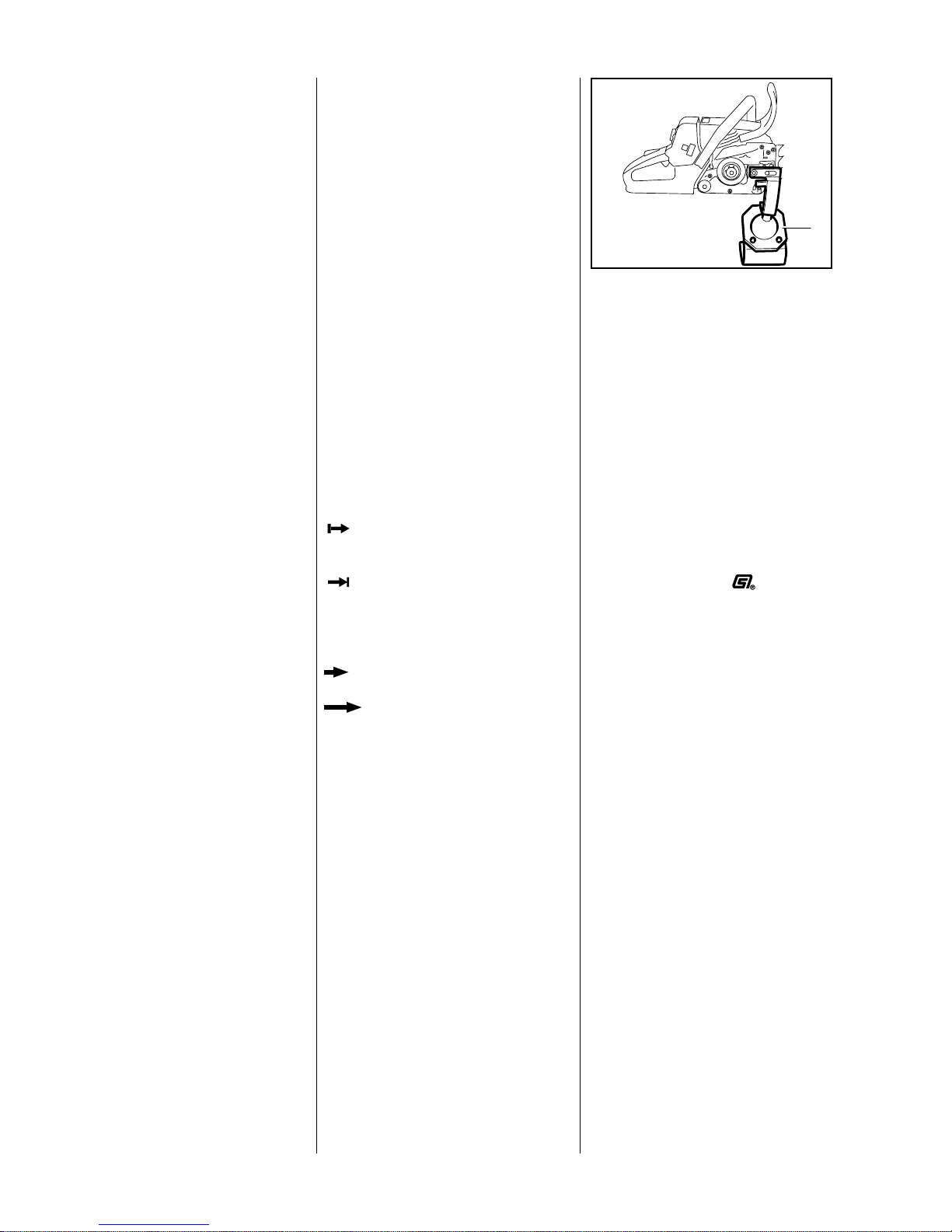
Servicing and repairs are made
considerably easier if the
powerhead is mounted on assembly
stand (1) 5910 890 3100. Remove
the chain sprocket cover, bar and
chain first.
The powerhead can then be
swivelled to the best position for the
VA
138RA001
1
ongoing repair. This leaves both
hands free.
Always use original STIHL
replacement parts.
They can be identified by the
STIHL part number,
the
67,+logo and the
STIHL parts symbol
This symbol may appear alone on
small parts.
1 Introduction
Page 3

3034, 036, 036 QS
If the engine is started up in the
course of repairs or maintenance
work, observe all local and countryspecific safety regulations as well
as the safety precautions and
warnings in the owner’s manual.
Gasoline is an extremely flammable
fuel and can be explosive in certain
conditions.
Improper handling may result in
burns or other serious injuries.
Warning!
Do not smoke or bring any fire,
flame or other source of heat near
the fuel. All work with fuel must be
performed outdoors only. Spilled
fuel must be wiped away
immediately.
2 Safety Precautions
Page 4

4 034, 036, 036 QS
3 Specifications
3.1 Engine
STIHL single cylinder two-stroke engine with special impregnated cylinder bore
034 036, 036 QS
Displacement:
Bore:
Stroke:
Compression ratio:
Engine power to ISO 8893:
Max. torque:
Max. permissible engine speed with
bar and chain:
Mean idle speed:
Crankshaft:
Main bearings:
Crankshaft journal diameter:
Big end bearing:
Piston pin diameter:
Small end bearing:
Connecting rod length:
Rewind starter:
Starter rope:
Clutch:
Diameter:
Clutch engages at:
Crankcase leakage test
at gauge pressure:
under vacuum:
56.5 cm
3
46 mm
34 mm
9.5:1
3.0 kW (4.1 bhp)
at 9,500 rpm
3.5 Nm
at 6,500 rpm
13,000 rpm
2,700 rpm
Two-part, drop forged
Two deep-groove ball bearings
14.4 mm
Needle cage
10 mm
Needle cage
58 mm
Pawl engagement with automatic
starter rope rewind mechanism
3.5 mm dia., 960 mm
Centrifugal clutch without linings
76 mm
approx. 3,500 rpm
0.5 bar
0.5 bar
61.5 cm
3
48 mm
34 mm
9.5:1
3.4 kW (4.6 bhp)
at 9,500 rpm
3.7 Nm
at 6,500 rpm
13,000 rpm
2,700 rpm
Two-part, drop forged
Two deep-groove ball bearings
14.4 mm
Needle cage
10 mm
Needle cage
58 mm
Pawl engagement with automatic
starter rope rewind mechanism
3.5 mm dia., 960 mm
Centrifugal clutch without linings
76 mm
approx. 3,500 rpm
0.5 bar
0.5 bar
3.2 Fuel System 034, 036, 036 QS
Carburetor:
Standard setting
High speed screw H:
Low speed screw L:
Idle setting:
Carburetor leakage test
at gauge pressure:
Fuel tank capacity:
Fuel mixture:
Mix ratio:
Air filter:
All positon diaphragm carburetor
with integral fuel pump
approx. 1 turn open
approx. 1 turn open
(starting with screws firmly against
their seats)
0.4 bar
625 cm
3
Regular brand-name gasoline and
brand-name two-stroke engine oil
50:1 with STIHL two-stroke engine
oil
25:1 with other brand-name twostroke, air-cooled engine oils
Large area, bisectional box filter
with wire mesh
Page 5

5034, 036, 036 QS
3.3 Ignition System
Type:
Air gap:
Spark plug (suppressed):
Electrode gap:
Spark plug thread:
Thread length:
Heat range:
034, 036, 036 QS
Transistorized magneto ignition
(breakerless)
0.2 - 0.3 mm
Bosch WSR 6 F
0.5 mm
M14x1.25
9.5 mm
200
3.4 Cutting Attachment
Guide bars:
Cutting lengths:
Oilomatic chain:
Chain sprockets:
Chain speed:
Chain lubrication:
Oil delivery rate:
Oil tank capacity:
STlHL Rollomatic S bars with nose
sprocket.
STlHL Duromatic bars with stellitetipped nose.
Both types with corrosion-resistant
finish and induction hardened rails.
Rollomatic 37, 40, 45 and 50 cm
Duromatic 37, 40, 45 and 50 cm
9.32 mm (3/8") Rapid-Micro,
Rapid-Super
(Options: 8.25 mm (0.325")
Rapid-Micro, Rapid-Super,
Topic-Micro and Topic-Super)
7-tooth, 3/8" rim sprocket
20.7 m/s at 9,500 rpm (with 7-toot h,
3/8" sprocket)
Fully automatic, speed-controlled
reciprocating oil pump; no oil feed
at idle speed. Additional manual oil
flow control
Adjustable 5.5 - 15.5 cm
3
/min
at 10,000 rpm
320 cm
3
Page 6

6 034, 036, 036 QS
3.5 Tightening Torques
DG and P (Plastoform) screws are used in polymer and lightmetal components. These screws form a
permanent thread when they are installed for the first time. They can be removed and installed as often as
necessary without impairing the strength of the screwed assembly, providing the specified tightening torque is
observed.
For this reason it is essential to use a torque wrench.
Fastener Thread size For component Torque
Nm
Remarks
Pan head screw M4x8 Chain tensioner cover plate 3.0
M7x12.5 Starter post to fan housing 12.0 1)
Screw M8x22 Brake band/crankcase
(036 QS II) 10.0 2)
Self-tapping screw B3.9x13 Brake cable retainer/tank housing (036 QS II) 1.5
Collar screw M8x21.5 Guide bar 23.0 2)
Spline screw IS-M4x12 Cover, chain brake/crankcase 3.0
M10x1 Decompression valve (036, 036 QS) 14.0
Spline screw M3.5x12 Generator (W version) 2.0 3)
Spline screw IS-P6x21.5 Front handle/tank housing, top right
(W version) 7.0 3)
Spline screw IS-P6x19 Front ha nd le /ta nk housing, bottom
(W version) 7.0 3)
Spline screw IS-P6x32,5 Front handle/tank housing, top right, polymer 5.0 3)
Spline screw IS-P6x21,5 Front handle/tank housing, bottom, polymer 5.0 3)
Spline screw IS-P4x19 Handle mo ldin g 1.6
Screw assembly M5x30 Hand guard, left 7.0 2)
Spline screw IS-P6x19 Chain catcher 2.8
Spline screw IS-M5x12 Spiked bumber 7.5
Spline screw IS-M5x20 Crankcase 9.0
Spline screw IS-M5x20 Fan housing/crankcase 7.0
M12x1 L Carrier 50.0
Screw HL6x18.5 Annular buffer to rear left/right of tank housing 5.0
Spline screw IS-P6x19 Annular buffer to front right of tank housing 5.0
Spline screw IS-M5x6 Muffler, upper/lower casing 6.5 2)
Spline screw IS-M5x25 Muffler/crankcase 10.0 2)
Spline screw IS-M5x16 Muffler/cylinder (036, 036 QS) 10.0 2)
Spline screw IS-M5x25 Muffler/crankcase (034) 10.0 4)
Spline screw IS-M5x20 Muffler/cylinder (034) 10.0 4)
Spline screw IS-M5x22 Muffler/cylinder (034/Z version) 10.0 4)
Slotted nut M5 Shroud 3.3
Slotted nut M5 Air filter 2.0
M8x1 Flywheel 33.0 6)
Setscrew M5x8.5 Setscrew, l/h side of cylinder 1.4 5)
Setscrew M5x8.5 Setscrew, r/h side of cylinder 1.4
Page 7

7034, 036, 036 QS
Hexagon nut M5 Carburetor (initial) 2.0
Hexagon nut M5 Carburetor (final) 3.5
Spline screw IS-M5x20 Cylinder/crankcase (036, 036 QS) 11.5
Spline screw IS-M5x20 Cylinder/crankcase (034) 10.5
M14x1.25 Spark plug 25.0
Spline screw IS-M5x20 Ignition module (with washer) 8.0 2)
Spline screw IS-M4x12 Oil pump/crankcase 3.5
1) Micro-encapsulated
2) Threadlocking method: medium strength adhesive (e.g . LOCTITE 243)
3) Threadlocking method: high strength adhesive (e.g. LOCTITE 649)
4) Threadlocking method: high strength adhesive up to 250 °C (e.g. LOCTITE 272)
5) Threadlocking method: high strength adhesive (e.g. LOCTITE 270)
6) Degrease taper with cleaning agent (e.g. Somentor 33)
Use the following procedure when refitting a DG or P screw in an existing thread:
– Place the screw in the hole and rotate it counterclockwise until it drops down slightly.
– Tighten the screw clockwise to the specified torque.
This procedure ensures that the screw engages properly in the existing thread and does not form a new thread
and weaken the assembly.
Note:
Power screwdriver settings for polymer:
– Plastoform screws max. 600 rpm
– DG screws max. 500 rpm
3.6 Special Accessories
3.6.1 For User
3.6.2 For Service
Intake air preheating kit
Intake air preheating kit
.325", 8-tooth rim sprocket kit
.325", 7-tooth rim sprocket kit
3/8", 7-tooth rim sprocket kit
3/8", 7-tooth spur sprocket
.325", 7-tooth spur sprocket
Gasket set
Carburetor parts kit
Gasket panel
034, 036, 036 QS
1125 007 1035 (036)
1125 007 1004 (034/034S)
1125 007 1000
1125 007 1001
1125 007 1002
1125 640 2000
1125 640 2005
1125 007 1050
1128 007 1065
0457 281 0604
Fastener Thread size For component Torque
Nm
Remarks
Page 8
8 034, 036, 036 QS
Troubleshooting chart - see
"Standard Repairs, Troubleshooting" handbook.
Unscrew nuts (1) from chain
sprocket cover (2). Remove the
sprocket cover , bar and chain (3).
VA
138RA002
1
2
3
Disengage the chain brake by
pulling the hand guard toward the
front handle.
VA
143RA004
Remove the E-clip (1) and
washer (2). If a rim sprocket (3)
is fitted, pull it off.
VA
148RA061
3
21
036 QS
Disengage the additional brake
by pressing down the throttle
trigger and interlock lever.
Remove the clutch drum (1) and
needle cage (2).
VA
148RA062
1
2
034, 036
Pull off the chain sprocket (1) or
clutch drum (2).
– Take out the needle cage.
VA
138RA003
1
2
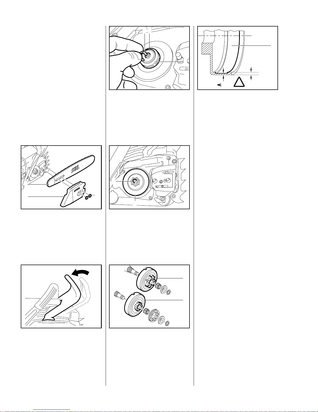
Inspect the clutch drum (1).
There should be no scores or
signs of excessive wear.
Important:
If there are signs of serious wear on
the inside diameter of the clutch
drum (1), check the remaining wall
VA
148RA101
80%
100%
1
!
thickness. If it is less than about
80% of the original thickness, fit a
new clutch drum.
Note:
Clean stub of crankshaft. Wash
needle cage, examine it for damage
and replace if necessary. Lubricate
needle cage with STIHL multipurpose grease - see 13.2.
Reassemble in the reverse
sequence - start by fitting the ne edle
cage on the crankshaft stub.
4 Clutch, Chain Drive,
Chain Brake and
Chain Tensioner
4.1 Clutch Drum and Chain Sprocket
Page 9
9034, 036, 036 QS
– Remove chain sprocket cover -
see 4.1.
Take out screw (1 ) an d re m ove
the inner side plate (2).
Take out screw (3 ) an d re m ove
the chain catcher (4).
VA
148RA063
2
1
3
4
Reassemble in the reverse
sequence.
Troubleshooting chart - see
"Standard Repairs, Troubleshooting" handbook.
– Remove clutch drum/chain
sprocket - see 4.1.
Release twist lock (1) on
carburetor box cover (2) and lift
cover off vertically.
VA
148RA064
1
2
Note:
When reassembling, check
correct position of groove and
guide.
VA
148RA065
Unscrew the slotted nut (1).
– Pull boot off the spark plug.
Remove the shroud (2).
VA
148RA066
2
1
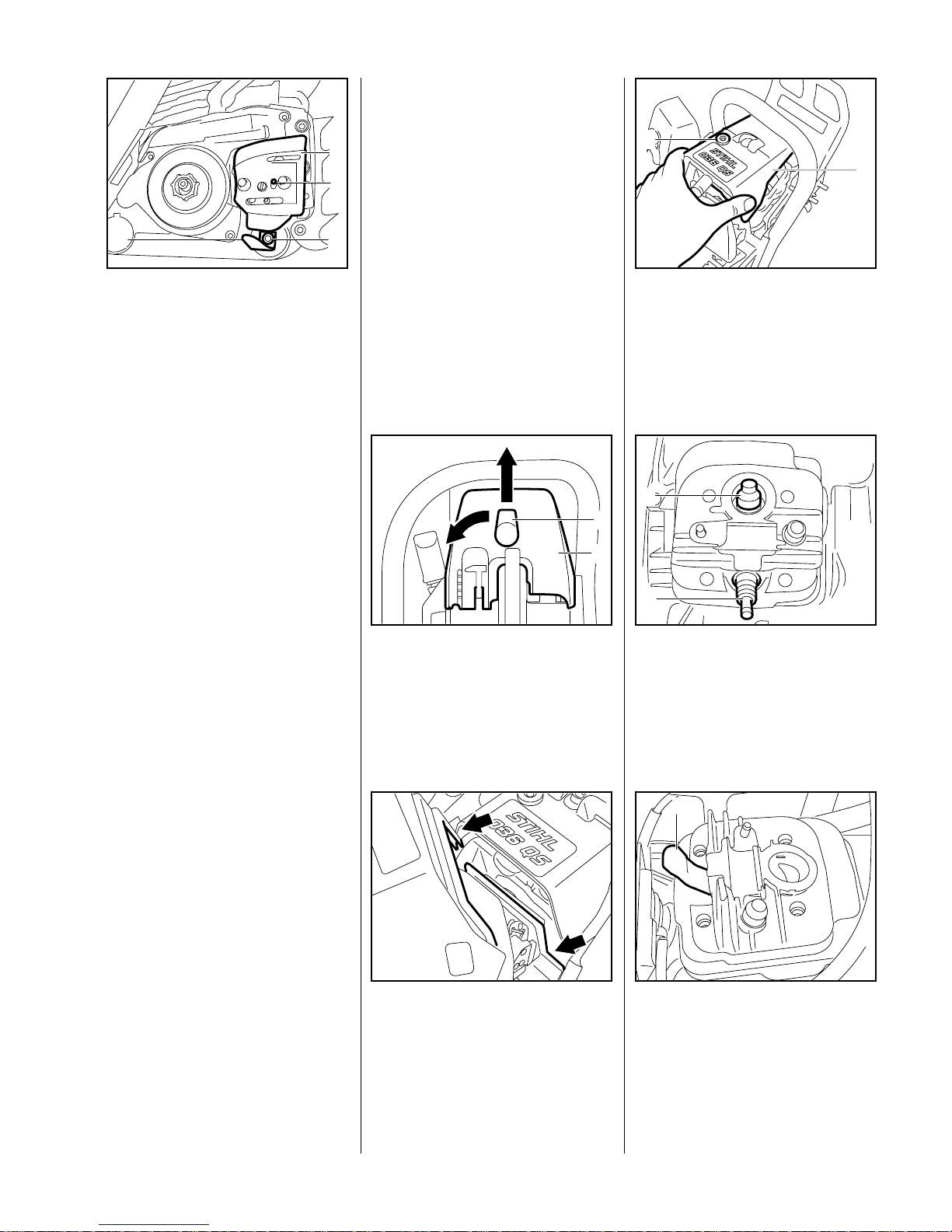
On powerheads with a
decompression valve (1), remove
the cover and unscrew the
decompression valve.
Unscrew the spark plug (2).
VA
148RA067
1
2
Push the locking strip (1)
0000 893 5903 into the cylinder
so that the words "OBEN - TOP"
face upward.
VA
148RA069
1
4.2 Replacing the
Chain Catcher
4.3 Clutch
Page 10
10 034, 036, 036 QS
Unscrew the clutch clockwise
from the crankshaft (left-hand
thread).
On 036, 036 QS:
Remove cover washer from the
crankshaft stub.
VA
148RA068
– Disassemble and reassemble the
clutch - see "Standard Repairs,
Troubleshooting" handbook.
– Reassemble in the reverse
sequence.
Note:
Observe tightening torque for clutch
(see "Tightening Torques").
Troubleshooting chart - see
"Standard Repairs, Tro ubleshooting" handbook.
– Remove the chain sprocket cover
and cutting attachment - see 4.1.
– Remove the clutch drum/chain
sprocket - see 4.1
Remove mounting screw (1 ) from
inner side plate (2) and lift side
plate away.
– Engage the chain brake by
pushing the hand guard away
from the front handle.
VA
138RA004
1
2
Remove mounting screws (1)
from cover (2) and lift the cover
away.
VA
138RA005
1
1
1
2
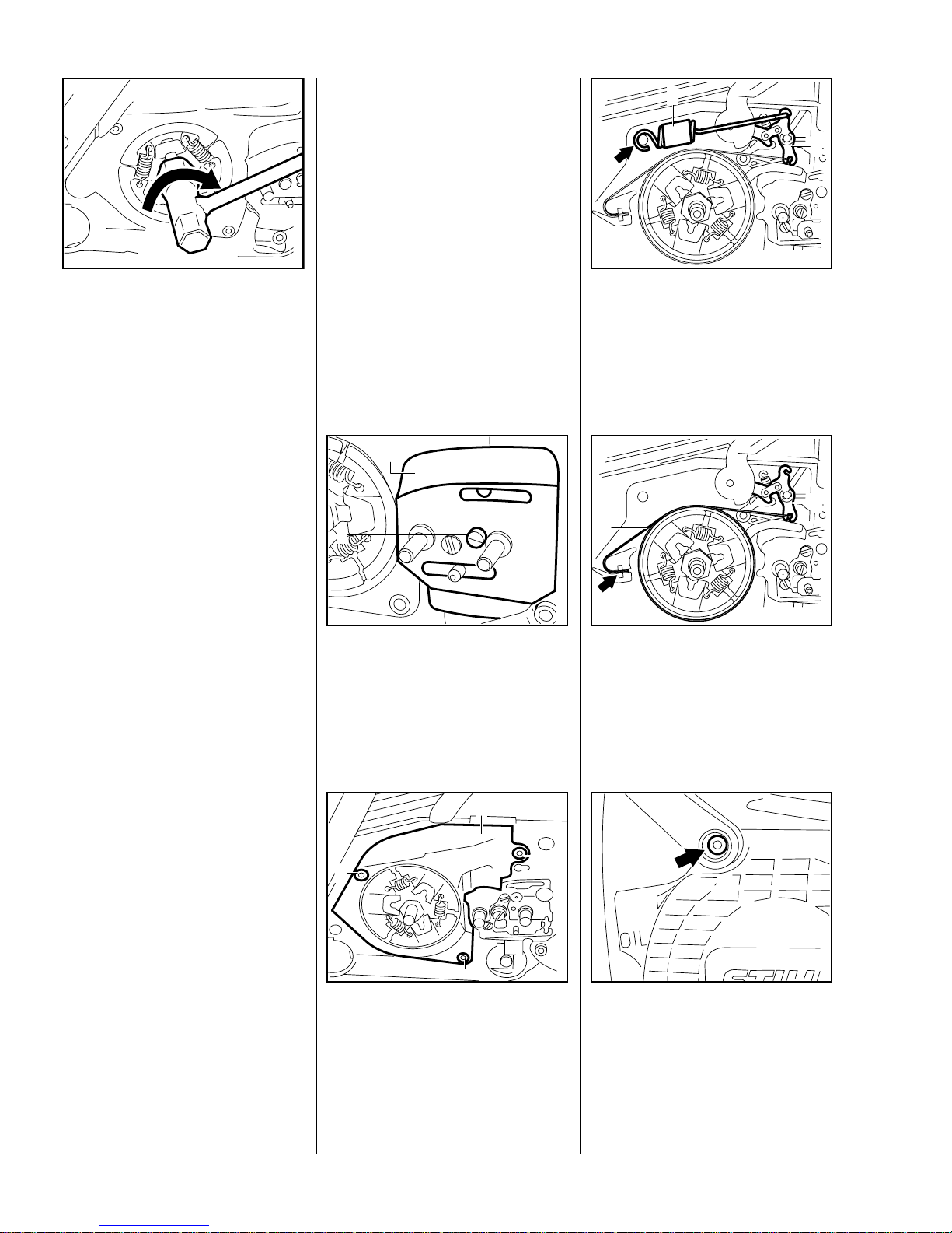
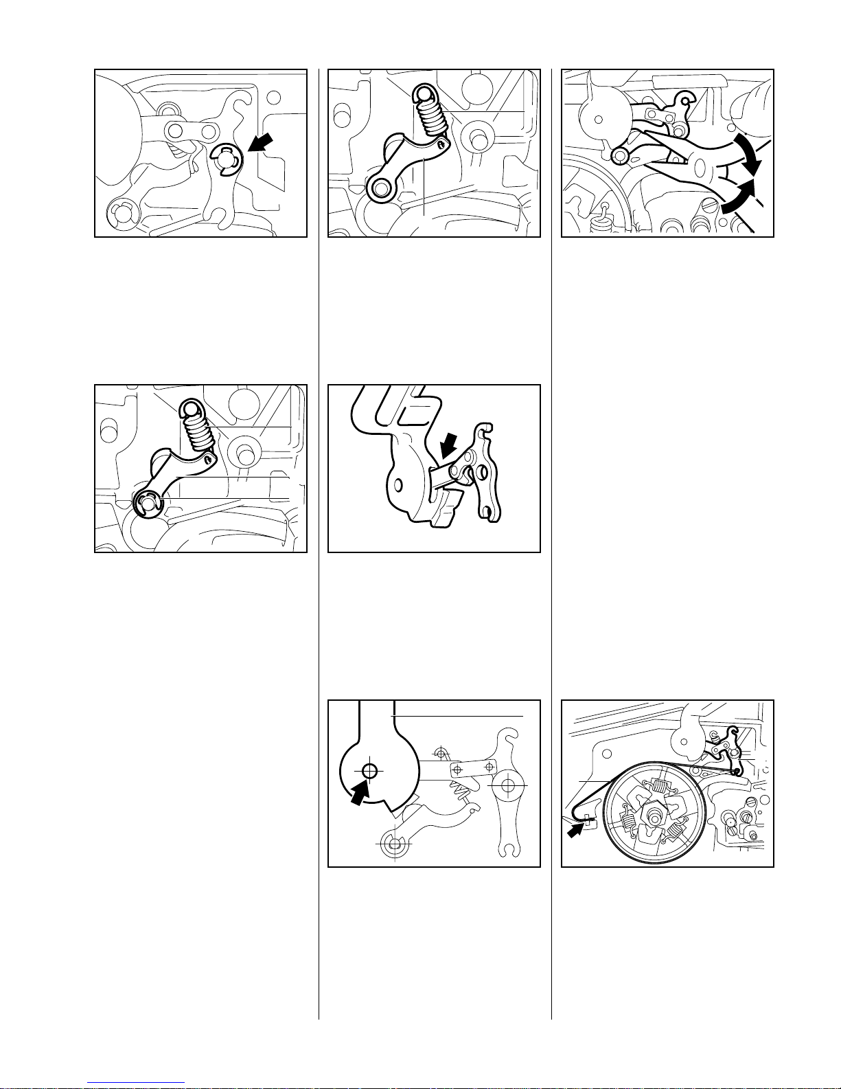
Carefully pry the brake spring (1)
off the anchor pin and disconnect
it from the lever (2).
VA
138RA006
1
2
Ease the brake band (1) out of
its seat in the crankcase and
disconnect it from the lever (2).
VA
138RA007
1
2
Remove screw with captive
washer from the hand guard.
Note:
When installing, tighten down the
screw with captive washer firmly
(see "Tightening Torques").
VA
138RA008
4.4 Chain Brake (034, 036)
4.4.1 Removing
Page 11
11034, 036, 036 QS
Remove the E-clip from the pivot
pin.
– Pull the hand guard and lever
from the pivot pins.
VA
138RA009
– Pull the lever out of the hand
guard.
Remove the E-clip (3) from pivot
pin of lever (2) and detach the
spring (1).
Remove the cam lever and
VA
138RA010
1
2
3
spring.
– Clean all disassembled parts in
white spirit. Replace any worn or
damaged parts.
Fit the cam lever (2) and
spring (1).
– Fit the E-clip.
VA
1
2
138RA011
Insert lever in th e side of the hand
guard so that short arm of lever
points up.
Note:
Check correct installed position of
lever.
VA
138RA012
Position the hand guard (1)
against the pivot pin and fit the
other side of the hand guard over
the fan housing.
VA
138RA013
1
Press the cam lever slightly
downward and push the hand
guard and lever onto the pivot
pins.
– Secure lever with E-clip.
– Insert hand guard mounting
VA
138RA014
screw with captive washer at fan
side and tighten down firmly (see
"Tightening Torques")
Important:
Coat all sliding and bearing points
with STIHL multipurpose grease,
see 13.2, or (better) with
molybdenum grease (e.g.
Molykote), see 13.2.
Do not lubricate the brake band.
First att ach the brake band (1) to
the lever (2) and then push it into
the crankcase recess (arrow).
VA
138RA007
1
2
4.4.2 Installing
Page 12
12 034, 036, 036 QS
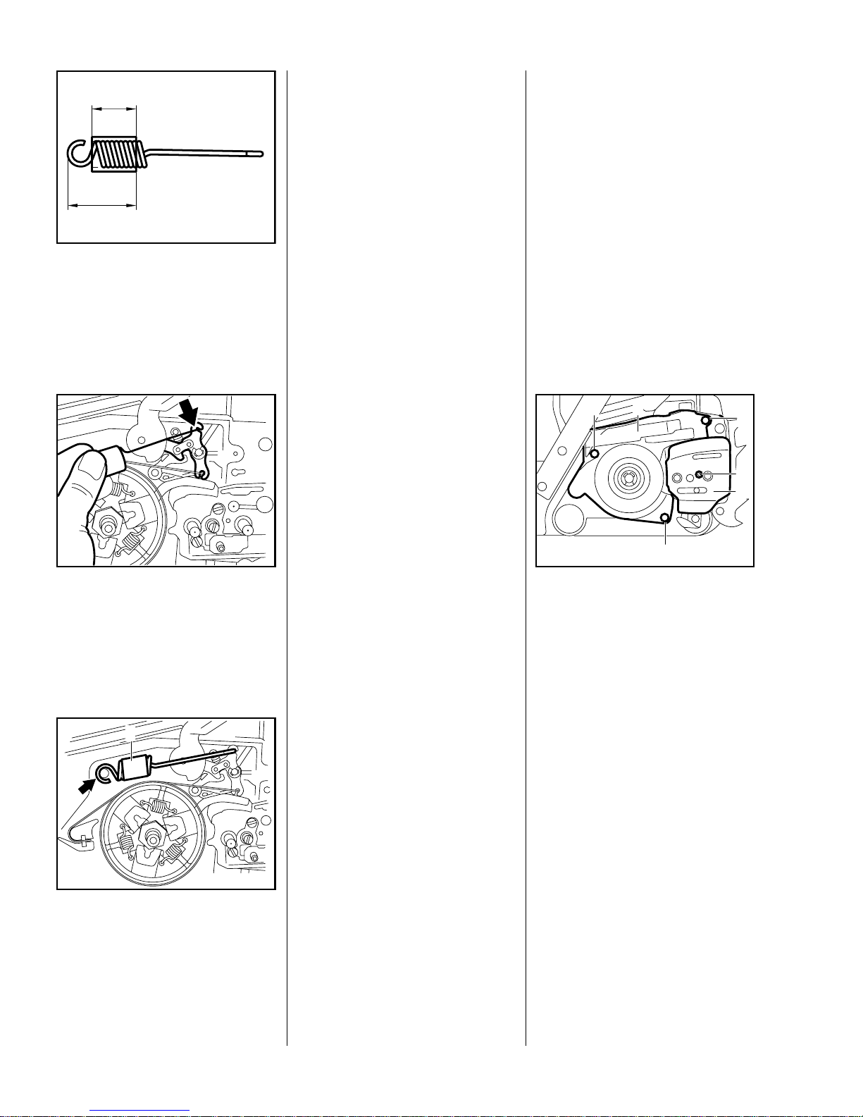
Check that protective tube is
correctly positioned:
a = 20 mm
b = 33 mm
b
a
VA
138RA016
Hook the brake sp ring to the
lever.
VA
138RA017
Use the assembly tool
1117 890 090 0 to at tach the
brake spring (1) to the anchor pin.
– Fit cover over the chain brake.
VA
138RA015
1
– Fit the inner side plate - see 4.1.
– Install the clutch drum/chain
sprocket - see 4.1.
– Fit the cutting attachment and
chain sprocket cover - see 4.1.
Troubleshooting chart - see
"Standard Repairs, Troubleshooting" handbook.
– Remove the chain sprocket cover
and cutting attachment - see 4.1.
– Remove clutch drum/chain
sprocket - see 4.1.
Remove mounting screw (1) from
inner side plate (2) and lift side
plate away.
Remove mounting screws (3)
from cover (4) and lift the cover
away.
VA
148RA070
4
2
3
3
3
1
– Engage the chain brake by
pushing the hand guard away
from the front handle.
4.5 Chain Brake (036 QS)
4.5.1 Removing
Page 13
13034, 036, 036 QS
Carefully pry the brake spring (1)
off the anchor pin and disconnect
it from the lever (2).
VA
148RA071
1
2
Remove the screw (1).
Ease the brake band ( 2) out of
its seat in the crankcase and
disconnect it from the lever (3).
3
2
1
VA
148RA072
Remove screw with captive
washer from the hand guard.
Note:
When installing, tighten down the
screw with captive washer firmly
(see "Tightening Torques").
VA
138RA008
Carefully pry spring (1) off the
pivot pin.
VA
148RA073
1
Pull the hand guard (2) and brake
lever (1) off the pivot pins.
VA
148RA074
2
1
Disconnect brake cable ( 1) from
the brake lever (2).
– Take the brake lever out of the
hand guard.
VA
148RA075
2
1
Disconnect spring (1) from
lever (2).
Pry the E-clip (3) off the pivot pin
and remove the lever with spring.
Clean all disassembled parts in
VA
148RA076
1
2
3
white spirit. Replace any worn or
damaged parts.
Page 14
14 034, 036, 036 QS
Fit the lever (2) and spring (1).
Fit the E-clip (3).
VA
148RA076
1
2
3
Insert lever in the side of the hand
guard as shown.
VA
148RA077
Attach brake cable (1) to hole
(arrow) in brake lever (2).
VA
148RA075
2
1
Position the hand guard (1)
against the pivot pin and fit the
other side of the hand guard over
the fan housing.
Press the lever (1) slightly
downward and push the hand
guard and brake lever (2) onto
VA
148RA078
1
2
the pivot pins.
– Insert screw with captive washer
for hand guard and tighten down
firmly (see "Tightening Torques").
Important:
Coat all sliding and bearing points
with STIHL multipurpose grease,
see 13.2, or (better) with
molybdenum grease (e.g.
Molykote), see 13.2.
Do not lubricate the brake band.
Attach spring (1) to the pivot pin.
VA
148RA073
1
First att ach the brake band (2) to
the brake lever (3) and then pu sh
it into the slot in the crankcase.
Install screw (1) with LOCTITE
243 and tighten down firmly (see
"Tightening Torques")
3
2
1
VA
148RA072
Hook the brake spring (1) to the
brake lever (2).
VA
148RA071
1
2
4.5.2 Installing
Page 15
15034, 036, 036 QS
Use the assembly tool
1117 890 090 0 to at tach the
brake spring (1) to the anchor pin.
– Fit cover over the chain brake -
see 4.5.1.
– Fit inner side plate - see 4.5.1.
VA
148RA098
1
– Install the clutch drum/chain
sprocket - see 4.1.
– Fit the cutting attachment and
chain sprocket cover - see 4.1.
– Pull hand guard toward front
handle.
– Unscrew nut from chain sprocket
cover and remove the cover - see
4.1.
– Remove the cutting att a chment -
see 4.1.
Take out screw (1) and remove
the side plate (2).
Take out screws (3) an d re m ove
the cover (4).
VA
148RA070
4
2
3
3
3
1
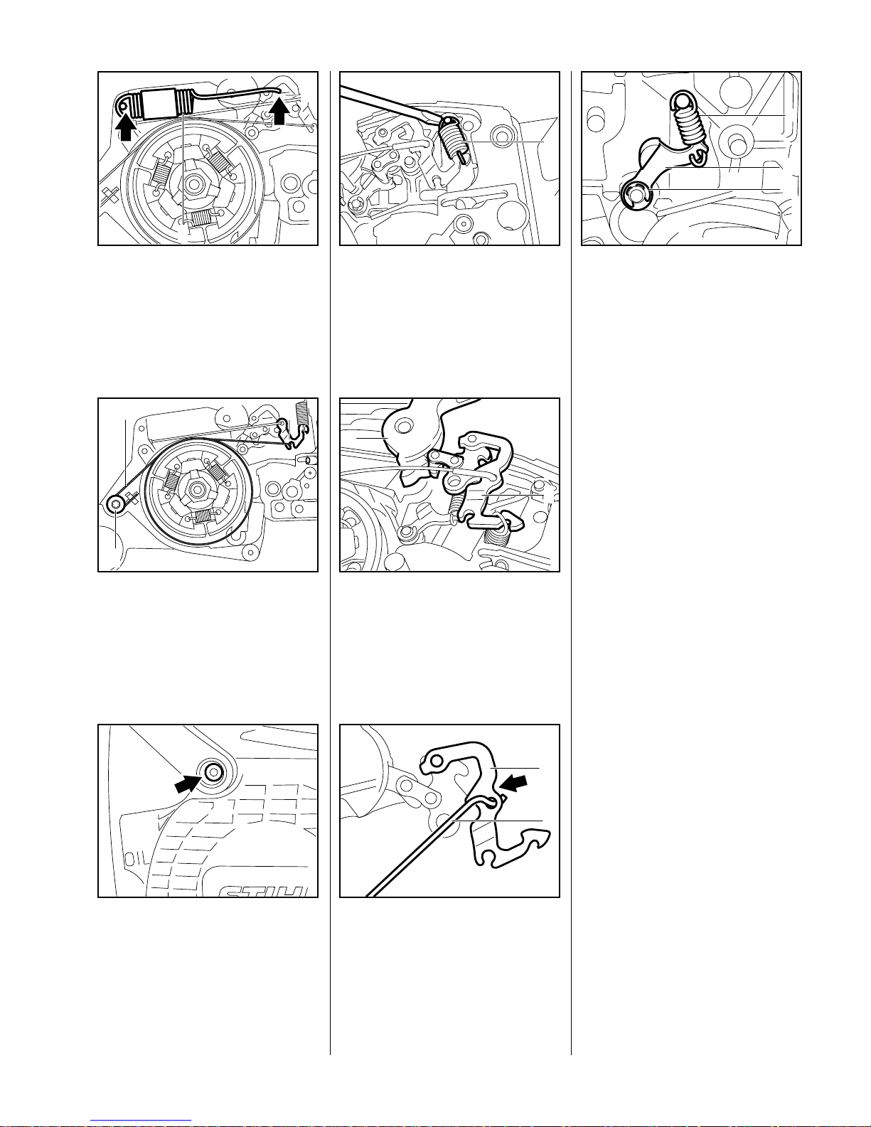
The brake cable (1) must hang
loosely in the crankcase when
the brake is disengaged.
VA
148RA079
1
Press down interlock lever (1) all
the way and hold it in that
position.
VA
148RA080
1
The brake band (1) must locate
without any play against the
points (A) in the crankcase.
VA
148RA081
A
A
A
A
A
1
A
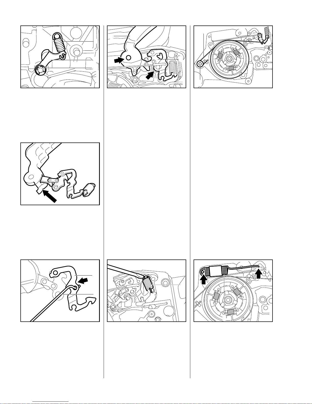
Let go of the interlock lever (1).
Check free travel by slowly
squeezing the interlock lever (1).
Play must be within the mark (B)
at the front end of the interlock
lever.
VA
148RA082
1
B
4.5.3 Checking Play
Page 16
16 034, 036, 036 QS
The brake lever must not move. If
it does, adjust play - see 4.5.4
Reassemble in the reverse
sequence.
Open twist lock (1) and lift away
the carburetor box cover (2)
vertically.
VA
148RA064
1
2
Release and unscrew slotted
nuts (1).
Remove the air filter (2).
VA
148RA084
2
11
Loosen the self-tapping
screw (1).
Use a 6mm open-end wrench to
adjust play with nut (2).
VA
148RA085
1
2
Turn wrench to right to reduce
play.
Turn wrench to left to increase
play.
Lock the setting with se lf-tapping
screw (1).
Reassemble in the reverse
sequence.
4.5.4 Adjusting Play
Page 17
17034, 036, 036 QS
Check operation of the chain brake
with the bar and chain mounted.
Note:
When starting the machine observe
local safety regulations and the
safety precautions in the owner’s
manual.
– With the engine running, open
the throttle wide.
– Release the rear handle.
The chain must come to a standstill
in less than one second.
If the brake does not operate
properly, service the sliding and
bearing points shown in the
illustrations as follows:
If lightly contaminated:
– Clean all parts with a brush and
white spirit.
If heavily contaminated or
clogged with resin:
– Remove the parts concerned and
clean in white spirit or a resin
solvent.
– Replace worn or damaged parts.
– Before re-installing parts, the
machine recesses and seats.
Lubricate bearing points with
Mobilplex grease (see 13.2).
VA
148RA047
Lubricate these points (1) with
Mobilplex grease (see 13.2).
Coat outside diam eter of clutch
drum (2) with chain oil.
Note:
If a biological chain oil is preferred,
VA
148RA048
1
1
2
2
STIHL recommends the use of
rapidly biodegradable STIHL
Bioplus.
To guarantee t roublefree oper ation,
use only original STIHL replacement parts as per the latest parts
list.
– Remove chain sprocket cover
and cutting attachment - see 4.1.
Remove mounting scre w (1) from
inner side plate (2) and lift side
plate away.
VA
138RA004
1
2
Use a screwdriver to turn the spur
gear clockwise until tensioner
slide butts against the thrust pad.
Note:
Older machines are equipped wi th
a front chain tensioner - see 5.5.2.
148RA086
VA
4.5.5 Checking Operation of Chain Brake 4.6 Chain Tensioner
Page 18
18 034, 036, 036 QS
Take out the cover plate
mounting screw (1).
Remove the cover plate (2) with
retainer (3) from the spur gear.
148RA087
VA
3
1 2
Pull out the spur gear (1).
Take out the tensio ne r slid e (3 )
with adjusting screw (4) and
thrust pad (2).
– Inspect the teeth on the spur gear
and adjusting screw, remove
VA
4 3
1
2
148RA088
thrust pad if necessary.
– Take the adjusting screw out of
the tensioner slide and replace
the parts.
Install in the reverse sequence.
Check that O-ring is fit ted in spur
gear.
– Lubricate O-ring with a little oil
before fitting the spur gear.
Note:
Coat teeth of adjusting screw and
VA
138RA018
spur gear with grease, see 13.2,
before refitting.
The adjusting screw and spur gear
must be replaced as a matching
pair.
– Remove chain sprocket cover
and cutting attachment - see 4.1.
Push stud puller 5910 893 0501
over the collar stud as far as it will
go. Use a 15 mm wrench to
unscrew the collar stud counterclockwise.
VA
138RA019
– Before installing, coat thread of
collar stud with LOCTITE - see
13.2.
– Install and tighten down t he collar
studs (see "Tightening Torques").
4.7 Bar Mounting Studs
Page 19
19034, 036, 036 QS
Always check and, if necessary,
repair the fuel system, carburetor,
air filter and ignition system before
looking for faults on the engine.
Troubleshooting chart - see
"Standard Repairs, Troubleshooting" handbook.
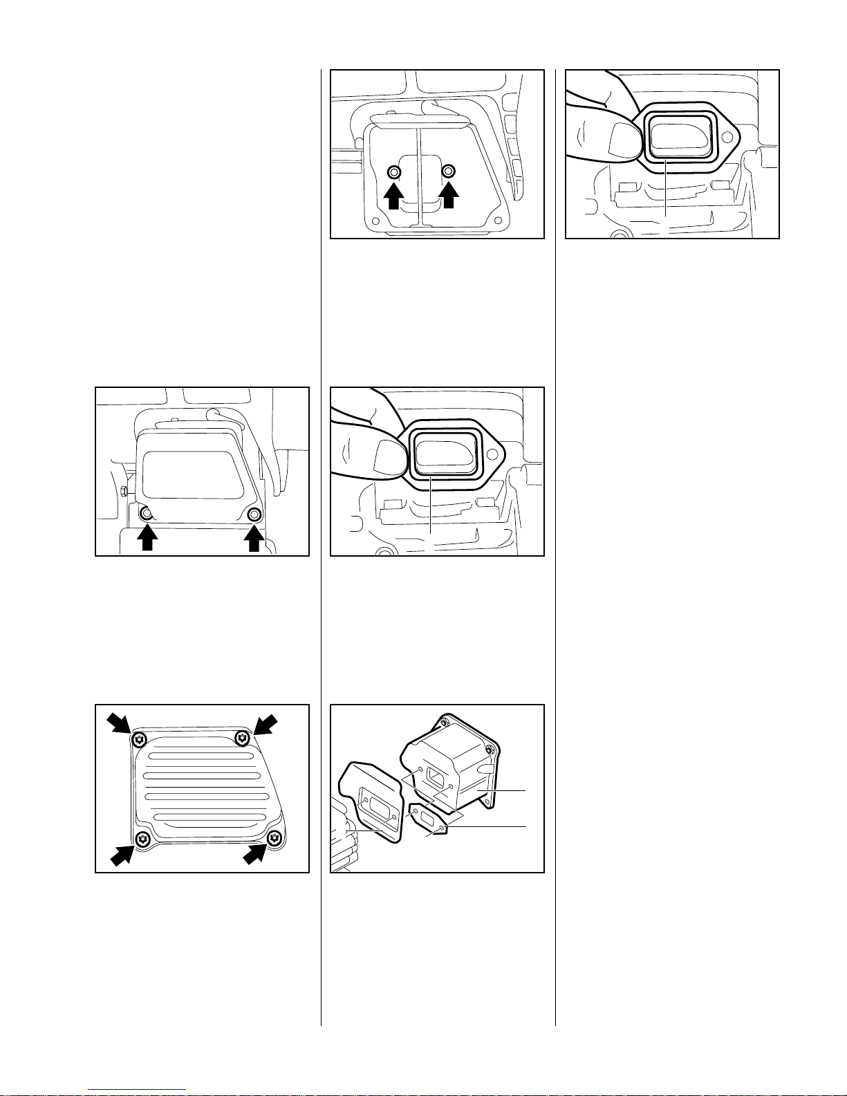
(034)
Take out the screws and remove
the upper casing.
VA
138 RA 219
(036, 036 QS)
Take out screws and remove the
upper casing.
VA
138 RA 220
Take out the screws and remove
the lower casing.
VA
138 RA 020
(034)
Remove exhaust gasket (1) and
flange.
VA
138RA021
1
(036, 036 QS)
Remove heat shield (1) and
gasket (2) from the upper
casing (3).
VA
138RA022
1
3
2
Install new gasket (1) so that its
bead points toward the muffler.
Note:
If the bores of the lower casing are
not reinforced, fit washers under the
heads of the mounting screws.
VA
138RA021
1
– Coat threads of mounting screws
with LOCTITE - see 13.2.
– Insert and tighten down the
mounting screws firmly (see
"Tightening Torques").
5Engine
5.1 Removing and Installing Muffler
Page 20
20 034, 036, 036 QS
Always check and, if necessary,
repair the fuel system, carburetor,
air filter and ignition system before
looking for faults on the engine.
Troubleshooting chart - see
"Standard Repairs, Troubleshooting" handbook.
– Drain the fuel and oil tanks.
– Remove the air filter - see 12.1
– Remove the carburetor - see 12.3
Pull the washer (1) off the studs
and remove the sleeve (2) from
the manifold.
– Remove the shroud, spark plug
and, if fitted, the decompression
valve - see 4.3.
VA
138RA023
1
2
– Remove the muffler - see 5.1
Reassemble in the reverse
sequence.
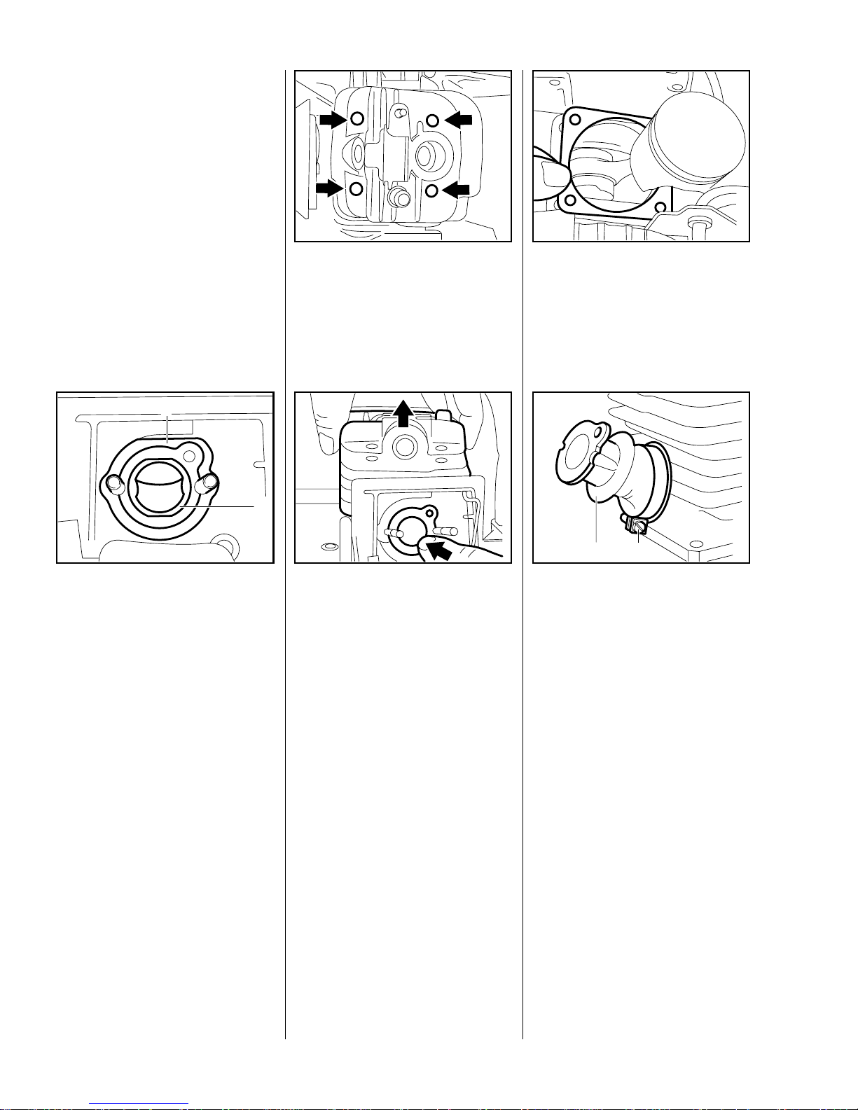
– Preparations - see 5.2
Take out the four cylinder base
screws.
VA
148RA089
Pull the cylinder off the piston
and, at the same time, push the
manifold through the tank
housing opening.
Caution:
Do not use pointed or sharp-edged
tools for this job.
VA
138RA024
Remove the cylinder gasket.
VA
138RA025
Release the hose clamp (1) on
the manifold (2). Pull the manifold
off the intake port.
– Inspect the cylinder and replace it
if necessary.
Note:
VA
138RA026
12
If a new cylinder has to be installed,
always fit the matching piston. New
cylinders are only supplied
complete with piston for this reason.
5.2 Exposing the Cylinder 5.3 Cylinder and Piston
5.3.1 Removing
Page 21
21034, 036, 036 QS
Important:
Before removing the piston, decide
whether or not the crankshaft has to
be removed as well.
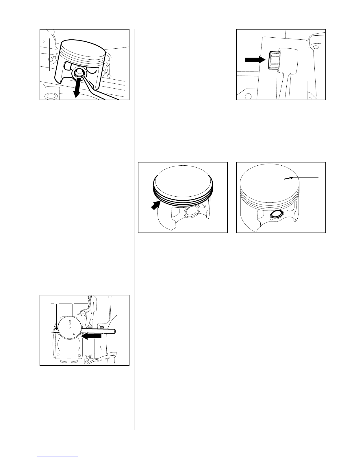
To remove the flywheel and
clutch, block the crankshaft by
sliding the wooden assembly
VA
138RA027
1
block (1) 1 108 893 4800 between
the piston and crankcase.
Use a scriber or similar tool to
ease the hookless snap rings out
of the grooves in the piston.
Use the assembly drift (2)
1 1 10 893 4700 to push the pist on
pin (1) out of the piston.
Note:
– If the piston pin is stuck, tap the
end of the drift lightly with a
hammer if necessary.
VA
138RA028
1
2
Important: Hold the piston
steady during this process to
ensure that no jolts are
transmitted to the connecting rod.
– Remove piston and take the
needle cage out of the
connecting rod.
Inspect piston r ings and replace if
necessary - see 5.4.
VA
138RA029
– Thoroughly clean the gasket
seating surface on the cylinder.
Lubricate the need le cage with oil
and fit it in the small end.
VA
138RA030
Install a snap ring in the front
piston boss (2), i.e. the piston
boss facing you when the arrow
(1) on the piston head is pointing
to the right.
Note:
Use installing tool 5510 890 2210 to
VA
138RA031
1
2
fit the snap ring - see "S tandard
Repairs, Troubleshooting"
handbook.
– Heat the piston on an electric
heating plate to about 60°C.
5.3.2 Installing
Page 22
22 034, 036, 036 QS
Slip the piston over the
connecting rod so that arrow on
piston crown points to exhaust
port.
VA
138RA032
– Push the assembly drift
1110 893 4700, sma ll dia m et er
first from the clutch side, through
the piston and small end (needle
cage) and line up the piston.
Fit piston pin on the end of the
assembly drift and push it into the
VA
138RA033
piston.
– Use installing tool 5910 890 2210
to fit the snap ring - see "S tandard
Repairs, Troubleshooting"
handbook.
– Fit new cylinder gasket on the
crankcase.
– Lubricate piston and piston rings
with oil.
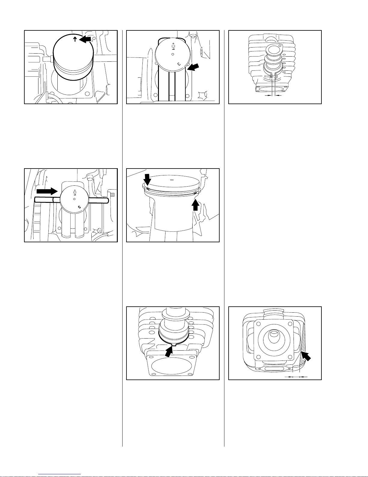
Slide the wooden assembly
block between the piston and
crankcase.
Rest the piston on the wooden
assembly block.
VA
138RA034
Position the piston rings so that
the radii at the ring gap meet at
the fixing pin in the piston groove
when the rings are compressed.
VA
138RA035
Push the manifold on to the
intake port so that its tab lines up
with the rib on the cylinder.
VA
138RA036
Slide the hose clamp on to the
manifold. The screw head must
point to the right.
The screw on the hose clamp
must be below the manifold and
at a right angle to the cylinder
axis.
a
VA
138RA037
Tighten the screw until the gap
"a" between the two ends of the
hose clamp is 3.5 to 4.5 mm.
Note:
If a new cylinder is installed in an
older machine, it is necessary to
shorten the seventh cylinder fin.
Use the edge of the eighth fin as a
guide for the modification (see
arrow in illustration).
VA
138RA038
7
8
10mm
Page 23

23034, 036, 036 QS
– Coat thread of setscrew in
cylinder with LOCTITE - see
13.2.
– Insert setscrew and t ighten down
firmly (see "Tightening Torques").
– Lubricate the inside of the
cylinder with oil and line it up so
that it is positioned as it will be in
the installed condition.
Use the clamping strap
0000 89 32600 to compress the
rings around the piston. Check
VA
138 RA 039
correct installed position of rings
once again.
Note:
T o make cylinder inst allation easier ,
apply clamping strap so that it is just
below the piston crown.
Slide the cylinder over the piston.
– Remove the wooden assembly
block and clamping strap.
VA
138 RA 040
Wind a piece of string (about
15 cm long) around the back of
the manifold flange, press the
manifold down and pass the ends
of the string through the intake
opening.
VA
138RA041
Pull the ends of the string
outward. The manifold flange is
pulled through the tank housing
intake opening without damaging
the manifold.
VA
138RA042
– Carefully line up the cylinder and
gasket.
– Fit cylinder base screws and
torque down firmly in a diagonal
pattern (see "Tightening
Torques").
Important:
It is essential to observe the
specified tightening torque as the
screws might otherwise work loose.
Assemble all other parts in the
reverse sequence. Always install
new gaskets.
Page 24

24 034, 036, 036 QS
– Remove the piston - see 5.3.1.
– Remove rings from piston.
Use a piece of old piston ring to
scrape the grooves clean.
Warning:
VA
138RA043
Do not install 1.2 mm rings in
pistons with 1.5 mm grooves.
Install the new piston rings in the
grooves so that the radii at the
ends of the rings face upward.
– Install the piston - see 5.3.2.
VA
138RA044
– Remove the chain brake - see 4.4
and 4.5.
– Remove the oil pump - see 11.4
– Remove the flywheel - see 6.4.1
– Remove the ignition module - see
VA
138RA045
6.5.1
– On machines with handle and/or
carburetor heating, remove the
generator - see 10.5.1.
– Remove the cylinder and piston -
see 5.3.1.
– Remove the tank housing - see
12.8.1.
– Remove the spiked bumper.
Use a 5 mm drift or other suitable
tool to drive out the two dowel
pins from the clutch side.
Unscrew the five mounting
screws which join the two halves
of the crankcase.
VA
138RA046
Use a screwdriver to rotate the
spur gear clockwise until the
tensioner slide butts against the
thrust pad.
Note:
Use service tools
AS 5910 007 2205 and
148RA086
VA
ZS 5910 007 2200 to remove and
install the crankshaft. Follow the
instructions supplied with the tools.
– Back off spindle on service tool
AS all the way.
Slip service tool
AS 5910 007 2205 over the two
collar studs, fit the hexagon nuts
(for sprocket cover) and tighten
them down by hand.
VA
138RA047
5.4 Piston Rings 5.5 Crankcase
5.5.1 Removing the Crankshaft
Page 25

25034, 036, 036 QS
Turn the spindle of the service
tool clockwise until the crankshaft
is pressed out of the ball bearing.
The two halves of the crankcase
separate during this process.
VA
138RA048
Fit thrust sleeve 1107 894 1000
from clutch puller 1107 890 4500
to protect the crankshaft thread
during the following operation.
VA
138RA049
Fit service tool
ZS 5910 007 2200 aga inst the
outside of the crankcase.
VA
138RA050
Note:
The tool’s drilled plate must locate
flat against the crankcase.
With the crankcase horizontal
(cylinder flange upright), rotate
service tool until the number 7 on
the plate is at the bottom.
Secure the service tool to the
crankcase with M5x72 mounting
screws 9022 341 1190. Insert the
screws in the holes marked "7"
and tighten them down against
the drilled plate.
– Turn spindle counterclockwise
VA
138RA051
(left-hand thread) until it locates
against the crankshaft.
– Use a 19 mm wrench to continue
turning the spindle and push the
crankshaft out of its bear ing seat.
The crankshaft (1), connecting
rod (2) and needle bearing form
an inseparable unit. This means
that the crankshaft must always
be replaced as a complete unit in
the event of damage to any one
of these parts.
VA
138RA052
1
2
– When fitting a replacement
crankshaft, always install new oil
seals and ball bearings.
– Remove the gasket from the
crankcase sealing face.
Use a screwdriver to pry the oil
seal out of the ball bearing at t he
clutch side.
VA
138RA053
Page 26

26 034, 036, 036 QS
Use press arbor 1118 893 7200
to press the ball bearing out of its
seat.
VA
138RA054
Use a screwdriver or similar tool
to knock the oil seal out of its seat
at the ignition side.
VA
138RA055
From outs ide the crankcase, use
arbor 1 120 893 7200 to pre ss the
ball bearing inwards and out of its
seat.
VA
138RA056
– Pull the oil suction hose out of
crankcase.
– Inspect both halves of the
crankcase for cracks and replace
if necessary.
Note:
Always install new gaskets and
ball bearings when replacing the
crankcase. The crankcase must be
replaced as a complete unit even if
only one half is damaged.
All other parts which are still
serviceable can be transferred to
the new crankcase after the new
bearings have been fitted
(crankcase has to be heated).
Use the stud puller 5910 893 0501
to remove and install the bar
mounting studs - see 4.7.
– If the original crankcase is used
again, remove all the gasket
residue and clean the mating
surfaces.
Note:
Clean the mating surfaces
thoroughly to ensure a perfect seal.
Note:
A new front chain tensioner is
supplied with replacement
crankcases.
1 Tensioner slide
2 Adjusting screw
3 Thrust pad
VA
138RA058
1 5
2
3
4
4 Cover plate
5 Pan head screw
– Stamp the machine’s serial
number on the crankcase with
2.5 mm figure stamps.
– Check that dowel pin is in
position. If necessary, drive
dowel pin into new crankcase.
5.5.2 Installing th e Crankshaft
Page 27

27034, 036, 036 QS
See illustrated parts list for correct
installed sequence and positions of
crankcase components.
Pull the plastic plug out of the oil
pump.
VA
138RA059
Position the oil pump ag ainst the
crankcase. Insert and tighten
down the mounting screws.
– Before heating the crankcase,
remove all rubber and polymer
VA
138RA060
components, such as oil suction
and delivery hoses, grommets,
annular buffers and levers - see
8.1 and 11.4.
– Inspect condition of all parts and
replace as necessary.
– Heat area of bearing seat on
clutch side of crankcase to
approx. 120°C.
Place ball bearing in posit ion and
press it in until it locates against
the oil pump.
Note:
The ball bearing can be fitted by
hand if the crankcase is heated as
specified. This operation must be
VA
138RA061
carried out very quickly because the
bearing absorbs heat immediately
and begins to expand.
– Remove the oil pump and refit the
plastic plug.
Push the two annular buffers,
tapered end first, into position so
that the groove (1) engages over
the housing rib.
VA
138RA062
1
Push the oil suction hose into the
crankcase bore.
VA
138RA063
Use a blunt tool to push the oil
suction hose into the bore so that
its tab locates in the bottom right
recess.
VA
138RA064
Page 28

28 034, 036, 036 QS
Fit the lever (1) over the pivot pin,
secure it with the E-clip and
attach the spring (2).
Install the chain tensioner (3) -
see 4.6
VA
138RA065
1
2
3
– Heat area of bearing seat on
ignition side of crankcase to
approx. 120°C.
Use press arbor 1118 893 7200
to install the ball bearing (open
side up).
VA
138RA066
Important:
the ball bearing is closed at one
side. The open side must be on the
inside of the crankcase to
guarantee proper lubrication.
Note:
The ball bearing can be fitted by
hand if the crankcase is heated as
specified. This operation must be
carried out very quickly because the
bearing absorbs heat immediately
and begins to expand.
Push annular buffer into
crankcase bore, from outside,
until its groove (1) engages the
inner rib.
VA
138RA067
1
Extend the spindle of service tool
ZS (2) 5910 007 2200 fully and
then screw the threaded sleeve
(1) 5910 893 2420 onto the
spindle as far as it will go.
VA
148RA093
21
Lubricate short crankshaft stub
with oil and position it in the
bearing from inside the ignition
side of the crankcase.
VA
148RA090
Important:
The original crankshaft must not be
installed in model 034S.
Apply threaded sleeve (1) to
thread (2) on crankshaft stub.
VA
148RA091
1 2
Hold the service tool and
crankshaft steady and continue
turning the spindle clockwise until
the service tool butts against the
crankcase.
VA
148RA092
Page 29

29034, 036, 036 QS
T urn the spindle clockwise to pull
in the crankshaft until it locates
against the ball bearing.
Important:
The connecting rod must point
toward the cylinder flange while the
crankshaft is being installed.
VA
138RA069
– Remove service tool ZS: First
release the spindle counterclockwise and then unscrew the
service tool ZS, also counterclockwise.
– Screw the spindle fully into
service tool AS 5910 007 2205 in
the clockwise direction.
Screw threaded sleeve (2)
5910 893 2409 onto the spindle
of service tool AS (1) as far as it
will go (left-hand thread)
– Lubricate crankshaft stub at
clutch side with oil.
VA
138RA070
2
1
– Fit crankcase gasket.
– Push the clutch side of the
crankcase over the crankshaft
stub as far as it will go.
To prevent the crankcase
and gasket twisting, fit M5x72
screws (1) (from service tool
ZS 5910 007 2200) in two
crankcase holes).
VA
138RA071
1
2
1
3
– Push threaded sleeve over the
crankshaft stub.
– Hold the crankshaft steady
and rotate the spindle counterclockwise to screw the threaded
sleeve onto the crankshaft.
Release the crankshaf t. Hold the
service tool (2) steady and
continue turning the spindle until
the tool locates against the guide
bar mounting face.
Fit the two hexagon nuts (3) on
the bar mounting studs and
screw them down finger-tight.
Turn the spindle counterclock-
wise until the crankshaft locates
against the ball bearing.
VA
138RA072
Page 30

30 034, 036, 036 QS
– Unscrew the hexagon nuts.
Unscrew the spindle clockwise
and take away the service tool.
– Take out the two M5x72 screws.
Drive home the two dowel pins.
VA
138RA073
Fit the five crankcase mounting
screws and tighten them down
alternately in a diagonal pattern
(see "Tightening Torques").
VA
138RA046
Trim away any excess gasket
material in the area of the
cylinder mounting face.
VA
138RA074
If the crankshaft does not turn
freely, it is sufficient to tap the
end of the stub with a plastic
mallet to relieve axial stresses.
VA
138RA075
Before installing oil seal, coat
cavity between dust and sealing
lips with grease - see 13.2.
VA
138RA076
Fit the installing sleeve (1)
1118 893 4602 over the clutch
end of the crankshaft.
Slip the oil seal (2), open side
facing the crankcase, over the
installing sleeve.
VA
138RA077
2
1
Press home the oil seal with
press sleeve (1) 1118 893 2401.
– Remove the installing sleeve.
VA
138RA078
1
Page 31

31034, 036, 036 QS
– Slide the oil seal, open side
facing the crankcase, over the
ignition end of the crankshaft.
Use press sleeve 1121 893 2400
to press home oil seal until sleeve
butts against the crankcase.
VA
138RA079
Important:
It is essential to observe the correct
installed depth of the oil seal to
achieve a proper seal. Always use
the press sleeve for this operation.
– Reassemble all other part s in the
reverse sequence.
Defective oil seals and gaskets or
cracks in castings are the usual
causes of leaks. Such faults allow
supplementary air to enter the
engine and thus upset the fuel-air
mixture.
This makes adjustment of the
prescribed idle speed difficult, if not
impossible.
Moreover, the transition from idle
speed to part or full throttle is not
smooth.
The crankcase can be checked
thoroughly for leaks with the
carburetor and crankcase tester
1106 850 2905 and the vacuum
pump 0000 850 3501.
– Remove the shroud from the
cylinder - see 4.3.
– T ake out the muf fler upper casing
mounting screws and remove the
upper casing - see 5.1.
Loosen the muffler lower casing
mounting screws about half way.
VA
138 RA 020
Fit sealing plate 0000 855 8106,
from above and narrow end first,
between the muffler lower casing
and cylinder exhaust port.
Note:
The sealing plate must completely
fill the space between the two
VA
138RA080
5.6 Crankcase Leakage Test 5.6.1 Preparatio n s
Page 32

32 034, 036, 036 QS
mounting screws. Push the narrow
end of the sealing plate home so
that it is just below the lower casing.
– Retighten the mounting screws
moderately.
– Remove the carburetor - see 12.3
– Set the piston to top dead center
(T.D.C.). This can be checked
through the inlet port.
– Remove screw 1128 855 9000
from test flange 1128 850 4200.
Fit the test flange (1), numbe r "1"
facing up and flat side first, on the
carburetor studs.
While fitting th e test flange, make
VA
148RA051
2
2
1
sure the impulse opening on the
manifold flange is properly
sealed (see arrow).
Fit the two hexagon nuts (2) and
tighten them down moderately.
– Preparations - see 5.6.1.
– Check tightness of spark plug
before starting leakage test.
– If decompression valve is fitted,
make sure it is tight and closed.
Connect pressure hose (1) of
tester 1 106 850 2905 to nipple on
test flange (2).
VA
148RA052
1
2
Close the vent screw (1) on the
rubber bulb.
VA
143RA046
1
– Pump air into the crankcase with
rubber bulb until the gauge
indicates a pressure of 0.5 bar . If
this pressure remains constant
for at least 20 seconds, the
crankcase is airtight.
– However, if the pressure drops,
the leak must be located and th e
faulty part replaced. Then repeat
the pressure test.
Note:
To find the leak, coat the suspe ct
area with oil and pressurize the
crankcase. Bubbles will appear if a
leak exists.
– Open the vent screw and
disconnect the hose.
– A pressure must always be
followed by a vacuum test - see
5.6.3.
– After finishing the tests,
reassemble all parts in the
reverse sequence.
Note:
Coat the mounting screws for the
upper and lower muffler casings
with LOCTITE. Insert and tighten
down the screws (see "Tightening
Torques").
5.6.2 Pressure Test
Page 33

33034, 036, 036 QS
Oil seals tend to fail when subjected
to a vacuum, i.e. the sealing lip lifts
away from the crankshaft during the
piston’s induction stroke because
there is no internal counterpressure.
An additional test can be carried out
with vacuum pump 0000 850 3501
to detect this kind of fault.
Connect suction hose of vacuum
pump 0000 850 3501 (1) to nipple
of test flange (2).
VA
148RA052
1
2
Close the vent screw (1) on the
pump.
Operate lever (2) until pressure
gauge (3) indicates a vacuum of
0.5 bar.
VA
232RA037
1
2
3
Note:
If the vacuum reading remains
constant, or rises to no more than
0.3 bar within 20 seconds, it can be
assumed that the oil seals are in
good condition. However, if the
pressure continues to rise (reduced
vacuum in the crankcase), the oil
seals must be replaced, even if no
leaks were detected in the pressure
test.
– After finishing the test,
reassemble all parts in the
reverse sequence.
Note:
Coat the mounting screws for the
upper and lower muffler casings
with LOCTITE. Insert and tighten
down the screws (see "Tightening
Torques").
It is not necessary to disassemble
the complete crankcase to replace
the oil seals.
– Remove the flywheel - see 6.4.1.
– Remove the Woodruff key from
the crankshaft stub.
On machines with handle or
carburetor heating system, take
out the generator mounting
screws, lift the generator away
and put it to one side.
– Remove the clutch - see 4.3.
VA
138RA084
– Remove the brake band - see
4.4.1 and 4.5.1.
– Remove the oil pump - see 11.4.
– Fit No. 3.1 jaws 000 893 3706 in
the universal oil seal puller
5910 890 4400.
5.6.3 Vacuum Test 5.7 Replacing the Oil Seals
Page 34

34 034, 036, 036 QS
Apply the puller at the clut ch side
and rotate the spindle clockwise
to pull the oil seal out of the
crankcase.
VA
138RA083
Apply the puller at the ignition
side and rotate the spindle
clockwise to pull the oil seal
out of the crankcase.
Important:
When using the puller, make sure it
does not damage the crankcase
VA
138RA085
surface or the ball bearing cages.
Install the oil seals as described
under 5.5.2.
– Install the generato r - see 10 .5.2 .
– Reassemble all other parts in the
reverse sequence.
Exercise extreme caution when
carrying out maintenance and repair
work on the ignition system. The
high voltages which occur can
cause serious or even fatal
accidents.
Troubleshooting on the ignition
system should always begin at the
spark plug - see "S tandard Rep airs,
Troubleshooting" handbook.
Note:
The electronic (breakerless) ignition
system basically consists of an
ignition module (1) and flywheel (2)
which requires no outside power
source (battery or dynamo). A
special flywheel (with ring magnet
for the generator) is installed in
VA
138RA086
2 1
models with handle or carburetor
heating system.
– Remove the air filter - see 12.1
– Pull boot off the spark plug.
– Remove the shroud - see 4.3
– Remove the ignition module - see
6.5.1
– Pull the ignition lead out of seat in
crankcase.
Unscrew the ignition lead (1) f rom
high voltage output on ignition
module (2).
– Pull the insulating tube off the
ignition lead.
VA
138RA087
1
2
Use a suitable pair of pliers to grip
the leg spring and pull it out of the
spark plug boot.
VA
138RA088
6 Ignition System 6.1 Ignition Lead/
Spark Plug Boot
Page 35

35034, 036, 036 QS
– Unhook the leg spring from the
ignition lead and slip the spark
plug boot off the lead.
– Coat the end of the ignition lead
and insulating tube (about
20 mm) with oil.
– Fit spark plug boot over the lead.
– Use a suitable pair of pliers to grip
the end of the ignition lead inside
the spark plug boot and pull it out.
Pinch the hook of the leg spring
into the center of the lead, i.e.
about 15 mm from the end of the
lead.
VA
138RA089
Pull the lead back into the boot so
that the leg spring locates
properly inside it.
VA
366RA104
– Use a pointed tool to pierce the
center of the other end of the
ignition lead.
– Slip the insulating tube over the
ignition lead.
– Screw the ignition lead into the
ignition module.
– Push the insulating tube right up
the ignition module’s high volt age
output.
– Install the ignition module - see
6.5.1.
– Push ignition lead into seat in
crankcase.
– Fit the shroud - see 4.3.
– Fit boot on the spark plug.
– Fit the air filter - see 12.1.
Note:
If the insulation of the short circuit
wire (2) is damaged it can cause a
short circuit to ground and upset or
completely interrupt ignition.
To remove the short circuit wire (2)
and ground wire (1), perform the
VA
138RA208
2
1
following operations:
– Remove the fan housing - see
6.4.
– Remove the shroud - see 4.3.
– Remove the air filter - see 12.1.
– Remove the tank vent - see 12.6.
Use a small screwdriver to ease
the connector sleeve of the short
circuit wire (1) out of its seat in the
switch shaft.
VA
138RA090
1
6.2 Short Circuit Wire/
Ground Wire
Page 36

36 034, 036, 036 QS
Pull ground wire connector
sleeve out of contact spring.
VA
138RA092
– On machines with handle or
carburetor heating, disconnect
the pin and socket connectors of
the heating systems - see 10.3.
Pull grommet out of t ank housing.
– Slip grommet off the wires.
VA
138RA211
– Pull the boot off the spark plug
and remove the ignition lead from
its seat in the crankcase.
– Pull the insulating tube through
the cable gland in the crankcase.
Removing the short circuit wire:
Disconnect short circuit wire f rom
ignition module.
– Pull short circuit wire out of
retainer on ignition module.
VA
138RA104
– Pull the short circuit wire through
the insulating tube.
– Install in the reverse sequence.
Note:
A ground wire is installed because
the contact spring in the polymer
tank housing is not connected to
ground on the ignition module.
Removing the ground wire:
Take out the screw (1) and
remove the ground wire (2).
VA
138RA093
2
1
– Pull the ground wire out through
the insulating tube.
– Install the new ground wire in the
reverse sequence. Check that
the insulating tube is properly
located in the crankcase cable
gland.
Important:
Use an ohmmeter to check correct
operation of the ground and short
circuit wires as well as the STOP
contact.
– Set the ohmmeter to measuring
range "Ω x 1".
Clip one of the two test leads to
the contact spring (1).
VA
138RA094
1
Clip the other test lead to the
ground wire terminal.
VA
138RA095
Page 37

37034, 036, 036 QS
– The ohmmeter must now show a
reading of 0 Ω. If no reading is
obtained, check the connection
between the contact spring and
connector sleeve.
Checking short circuit wire and
STOP contact :
– Leave one test lead clipped to the
contact spring.
– On machines with carburetor
heating, pull the thermostatic
switch’s flag connector off the
contact spring.
– Move the Master Control lever
upwards to "STOP".
– Clip other lead to short circuit
wire’s terminal.
– The ohmmeter must again show
a reading of 0 Ω. If no reading is
obtained, check the connection
between the connector sleeve in
the switch shaft’s cam and the
contact spring.
– On machines with carburetor
heating, push the thermostatic
switch’s flag connector onto the
contact spring.
– Remove the air filter - see 12.1
– Remove the tank vent - see 12.6.
The short circuit system is in
order if the short circuit wire
makes contact with the connector
sleeve when the Master Control
VA
138RA096
lever is in the "STOP" position.
Replacing a bent or broken
contact spring:
– T o avoid damaging the fuel hose,
pull it off the carburetor’s elbow
connector.
– On machines with carburetor
heating, pull the thermostatic
switch’s flag connector off the
contact spring.
Pull the ground wire connector
sleeve out of the contact spring.
– Move Master Control lever to
"STOP" position.
VA
138RA092
Squeeze the contact spring so
that is disengages from the
Master Control lever and, at the
same time, use a screwdriver to
pry it out of its seat in the
crankcase.
– Install the new contact spring.
VA
138RA097
– Reconnect the ground wire
connector sleeve.
Important:
– Check operation of the short
circuit wire - see 6.2.
– On machines with carburetor
heating, push the thermostatic
switch’s flag connector onto the
contact spring.
– Fit the tank vent - see 12.6.
– Fit the air filter - see 12.1.
6.3 STOP Contact
Page 38

38 034, 036, 036 QS
Take out mounting screws and
remove the fan housing.
– Rotate the flywheel so that the
magnet poles are opposite the
ignition module.
VA
138RA098
– Use locking strip 0000 893 5903
to block the piston - see 4.3.
Unscrew the flywheel mounting
nut from the crankshaft.
VA
138RA099
Screw puller 1110 890 4500 into
flywheel hub as far as stop.
Hold puller steady with a 24 mm
wrench and use a 17 mm wrench
to screw home the thrust bolt until
the flywheel comes away from its
seat on the crankshaft.
VA
138RA100
– Take off the flywheel.
– Inspect the flywheel. If you find
any damage (e.g. cracks, ,
broken fan blades), fit a new
flywheel.
Important:
If a new flywheel 1125 400 1208 is
installed in a machine with heated
handles
X 31 813 247, the
original front handle must always be
replaced by front handle
1125 790 1702 to take account of
the higher power output.
In addition, the new heating element
1 128 434 5000 must be fit ted in the
rear handle since the heating
elements may otherwise burn out.
The old front handle 1 125 790 1707
and the old heating elements
1125 434 5000 may only be
installed in machines with flywheel
1125 400 1207.
Front handles and heating elements
can be identified with the aid of the
following resistances:
Rear handle heating element:
Old version (1) 0.225...0.275 Ω
New version (2) 0.922...1.1 Ω
Front handle heating element:
Old version 1.44 ...1.76 Ω
New version 6.3 ...7.7 Ω
VA
148RA217
1 2
Check correct position of
Woodruff key.
VA
138RA101
Important:
– Clean the stub of the crankshaft
and the flywheel hub bore with a
standard commercial, solventbased degreasant containing no
chlorinated or halogenated
hydrocarbons - see 13.2.
VA
138RA102
– Fit the flywheel in position.
Fit and tighten down the flywheel
nut (see "Tightening Torques").
Reassemble all other parts in the
reverse sequence.
Observe tightening torques when
refitting the fan housing (see
"Tightening Torques").
6.4 Flywheel
6.4.1 Removing
6.4.2 Installing
Page 39

39034, 036, 036 QS
The ignition module accommodates
all the components required to
control ignition timing.
Ignition module components a nd
connections
1 Ignition lead with insulating tube
VA
138RA103
1
4
3
2
2 High voltage output
3 Ground wire
4 Connector tag for
short circuit wire
Accurate testing of the ignition
module is only possible with special
test equipment. For this reason it is
only necessary to carry out a spark
test in the workshop.
A new ignition module must be
installed if no ignition spark is
obtained (after checking that wiring
and stop switch are in good
condition).
– Remove the fan housing - see
6.4.1
Use a screwdriver to disconnect
the short circuit wire from the
ignition module.
VA
138RA104
Take out the two mounting
screws and lift away the ignition
module.
Note:
If the ignition module is faulty,
unscrew the ignition lead
counterclockwise and transfer it
VA
138RA105
along with the spark plug boot and
cable retainer to the new ignition
module.
– To install the ignition module,
connect short circuit wire to tag
on ignition module and then push
the short circuit wire into the
retainer.
– Place the ignition module in the
crankcase.
– Coat threads of ignition module
mounting screws with LOCTITE -
see 13.2.
– Use lower mounting screw to
connect the ground wire to the
ignition module.
Fit the two screws and tighten
them down moderately.
– Rotate the flywheel until the
magnets are between the two
arms of the ignition module.
Slide the setting gauge
1111 890 6400 or 0.2 mm metal
gauge between the arms of the
ignition module and the flywheel
magnets.
– Press the ignition module against
the flywheel and tighten down the
VA
138RA107
mounting screws (see
"Tightening Torques").
Important:
Tighten the upper screw first.
– Remove the setting gauge and
use a feeler gauge to check the
air gap. It should be 0.2 to
0.3 mm.
– Fit the fan housing - observe
tightening torques (see
"Tightening Torques").
6.5 Ignition Module 6.5.1 Removing and Installing
Page 40

40 034, 036, 036 QS
Ignition timing on electronic
(breakerless) magneto ignition
systems is fixed at 2.5 mm B.T.D.C.
at 8,000 rpm and is not adjustable.
However , in view of the permissible
tolerances in the electronic circuitry ,
it may vary between 1.8 and 2.6 mm
B.T.D.C. at 8,000 rpm.
Since there is no mechanical wear
in these systems, ignition timing
cannot get out of adjustment.
However, an internal fault in the
circuit can alter the switching point
in such a way that a spark test will
still show the system to be in order
although timing is outside the
permissible tolerance. This will
impair engine starting and running
behavior.
Troubleshooting chart - see
"Standard Repairs, Tro ubleshooting" handbook.
If the action of the starter rope
becomes very stiff and the rope
rewinds very slowly or not completely, it can be assumed that the
starter mechanism is in order but
plugged with dirt. At very low
outside temperatures the lubricating oil on the rewind spring may
thicken and cause the spring
windings to stick together . Th is has
a detrimental effect on th e function
of the starter mechanism. In such a
case it is sufficient to apply a few
drops of paraffin (kerosine) to the
rewind spring.
Then carefully pull out the starter
rope several times and allow it to
rewind until its normal smooth
action is restored.
If clogged with dirt or pitch, the
entire starter mechanism, including
the rewind spring, must be removed
and disassembled. Take special
care when removing the spring.
Wash all parts in paraffin/kerosine
or white spirit.
Lubricate the rewind spring and
starter post with STIHL special
lubricant, see 13.2, before inst alling.
– Remove the fan housing - see
6.4.1
Note:
For descriptions on removing and
installing the rope rotor, replacing
the starter rope, p awls or rope guide
bush - see "Standard Repairs,
Troubleshooting" handbook.
Observe tightening torques when
refitting the fan housing (see
"Tightening Torques").
6.5.2 Ignition Timing 7 Rewind Starter
7.1 Routine
Maintenance
7.2 Rope Rotor, Pawls,
Starter Rope,
Rope Guide Bush
Page 41

41034, 036, 036 QS
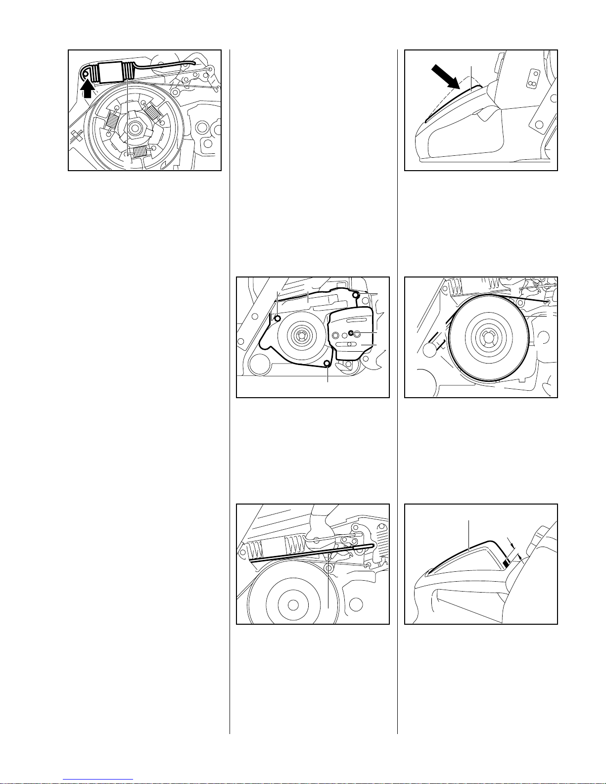
– Remove the rope rotor - see 7.2.
Use suitable pliers to grip the
anchor loop of the rewind spring
and lift it up.
– Take the sp ring housing and
rewind spring out of the fan
VA
138RA108
housing.
– Remove any remaining bits of
spring from the fan housing.
– Lubricate die rewind spring with
STIHL special lubricant and fit it
with the spring housing (bottom
plate facing up) in the fan
housing.
– Engage the spring loop over the
lug in the fan housing.
Warning:
The rewind spring may pop out and
uncoil during installation. If the
rewind spring has popped out, refit it
in the spring housing as follows:
Position anchor loop about
25 mm from the edge of the
spring housing.
VA
138RA109
Refit the rewind spring in the
spring housing in the counterclockwise direction, starting
outside and working inwards.
– Fit the spring housing in the fan
housing.
VA
138RA110
– Engage the spring loop over the
lug in the fan housing.
– Install the rope rotor - see 7.2.
– Tension the rewind spring - see
7.4.
– Remove the rope rotor - see 7.2.
– Use suitable pliers to grip the
anchor loop of the rewind spring
and pull it out carefully.
Warning:
The rewind spring jumps out of its
seat in the fan housing in this
process.
– Remove any remaining bits of
spring from the fan housing.
– Lubricate the rewind spring with
STIHL special lubricant.
Engage the anchor loop over the
lug in the fan housing and fit the
rewind spring in the fan housing
in the clockwise direction, starting
outside and working inwards.
– Install the rope rotor - see 7.2.
VA
148RA053
– Tension the rewind spring - see
7.4.
7.3 Rewind Spring
7.3.1 Replacing the Rewind Spring (034)
7.3.2 Replacing the
Rewind Spring
(036, 036 QS)
Page 42

42 034, 036, 036 QS
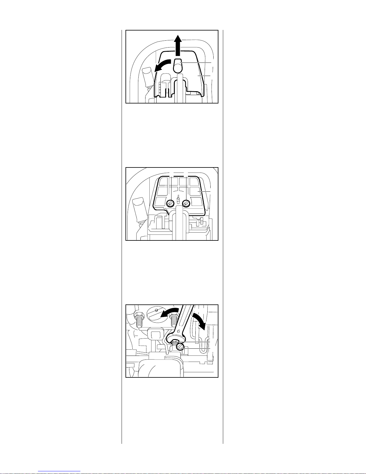
Grip the rope between the guide
bush and rotor, pull it out and
make a loop.
Hold the rope close to the rotor
and use it to turn the rotor about
five full turns clockwise.
138RA112
VA
– Hold the rope rotor steady.
Pull out the rope with the starter
grip and straighten it out.
– Hold the starter grip firmly to keep
the rope tensioned.
– Let go of the rope rotor and
slowly guide the starter grip back
VA
138RA113
so the starter rope can rewind
properly.
Note:
The rewind spring is correctly
tensioned when the starter grip sits
firmly in the rope guide bush without
drooping to one side. If this is not
the case, tension the spring by one
additional turn.
When the starter rope is fully
extended, it must still be possible to
rotate the rope rotor a t least another
half turn before maximum spring
tension is reached. If this is not the
case, pull the rope out, hold the
rope rotor steady and take off one
turn of the rope.
Do not overtension the rewind
spring as this will cause it to
break.
– Fit the fan housing - see 6.4.
The crankcase and tank housing
are connected by vibration damping
rubber buffers. Damaged rubber
buffers (annular buffers) must
always be replaced in sets.
Note:
When replacing annular buffers,
make sure you always install the
latest type.
Annular buffers must be replaced in
sets of the same hardness. Harder
buffers are installed for more
accurate control but reduced
vibration damping, while softer
butters provide better vibration
damping.
T o remove the annular buf fers at the
clutch side:
– Remove the chain sprocket cover
and cutting attachment - see 4.1.
– Remove the chain catcher - see
4.2.
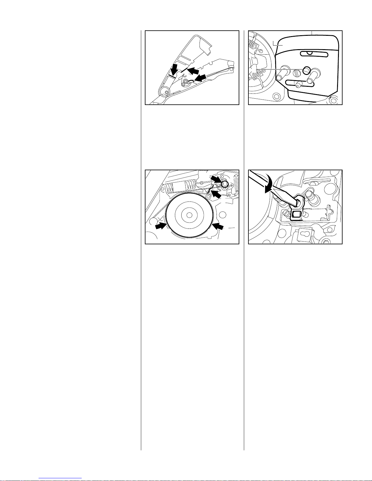
Use a screwdriver to remove the
two plugs from the annular
buffers.
VA
138RA115
7.4 Tensioning the Rewind Spring 8 AV Handle System
8.1 Repair
Page 43

43034, 036, 036 QS
– Take out the annular buffer
mounting screws.
– Use a screwdriver to pry the
annular buffers out of their seats.
To remove the annular buffer at the
ignition side:
– Remove the carburetor box cover
and shroud - see 4.3.
– Remove the fan housing - see
6.4.
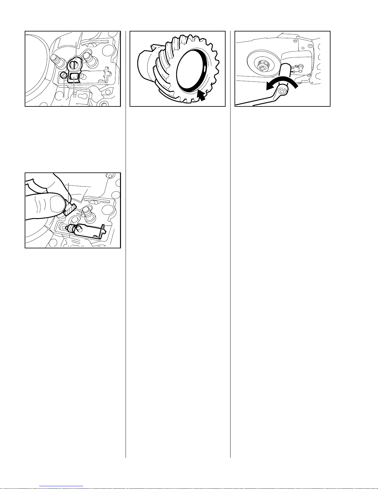
Use a screwdriver to ease the
plug (1) out of the annular buffer.
– Take out the annular buffer
mounting screw.
VA
138RA209
1
– Use a screwdriver to pry the
buffer out of its seat.
Note:
The tank housing has to be
removed, see 12.8.1 , to replace the
stop buffer.
– Take out the stop buffer and fit a
new one.
– Install the tank housing - see
12.8.1.
Installing new annular buffers:
Push the annular buffer, washer
first, into the crankcase seat un til
groove (1) engages over the
inner housing rib.
– Insert the mounting screw and
VA
138RA114
1
tighten it down firmly (see
"Tightening Torques").
– Lubricate the bead of the plug
with oil and then push it into the
annular buffer.
Reassemble all other parts in the
reverse sequence.
The main part of the Master Contro l
is the switch shaft with an integrally
molded multi-function operating
lever, a molded cam and a second
lever. The switch shaft located
forward of the rear handle in the
tank housing and is supported at
two points.
The Master Control lever moves the
switch shaft to select the required
function. The following positions
can be selected with the Master
Control lever:
STOP (1) (closes short circuit
contact and
interrupts ignition)
RUN (2) (normal operating
position)
VA
138RA116
4
3
2
1
The cam on the left holds the
connector sleeve of the short circuit
wire and is also the stop for locking
the Master Control lever in the
"RUN" position.
START (3) (warm start -
starting throttle/
choke shutter open)
CHOKE (4) (cold start -
starting throttle/
choke shutter
closed)
9Master Control
9.1 Construction and
Function
Page 44

44 034, 036, 036 QS
I
In the "STOP" position the
connector sleeve moves against the
contact spring (arrow).
VA
138RA096
The molded lever on the center of
the switch shaft operates the throttl e
trigger when the "START" and
"CHOKE" positions are selected:
VA
138RA117
The choke shutter actuating lever is
molded to the right-hand end of t he
switch shaft. It closes the choke
shutter when the Master Control
lever is set to "CHOKE".
VA
138RA118
– Remove the air filter - see 12.1
Take out the handle molding
fastening screw. Lift away the
handle molding.
VA
138RA120
– Move Master Control lever to
"RUN" position.
Pull the throttle interlock lever out
of its seat.
VA
138RA121
Detach throttle rod from the
trigger.
VA
138RA122
Use a 5 mm drift to drive out the
cylindrical pin (3). Take the
throttle trigger (2) and torsion
spring (1) out of the handle.
Install in the reverse sequence.
VA
138RA123
3
2
1
Note:
The torsion spring must be under
the interlock lever and locate in the
notch (arrow).
VA
138RA128
Press the interlock lever (1)
down, pull the throttle trigger (2)
up and move the Master Control
lever (3) to "CHOKE".
VA
138RA124
3 2
1
9.2 Throttle Trigger/Interlock Lever (034, 036)
Page 45

45034, 036, 036 QS
Fit the handle molding so that the
lug at its front end engages
properly under the seat on the
tank housing.
– Fit handle molding fastening
screw (see "Tightening
Torques").
VA
138RA125
– Remove the air filter - see 12.1.
Unscrew fastening screw (1)
from handle molding (2). Lift
away the handle molding.
148RA001
KV
1
2
Use a 3 mm drift to drive the
needle roller (2) out of the
interlock lever (1). Remove the
lever.
VA
148RA099
21
Use a 4.5 mm drift to drive the
bushing (1) out of the interlock
lever (2) and then remove the
torsion spring (3).
Install in the reverse sequence.
3
2
1
148RA100
VA
To remove the switch lever (1),
swing it back (arrow).
VA
148RA054
1
Disconnect brake cable (1) from
switch lever (2).
– Use a 3 mm drift to drive the
needle roller out of the switch.
– Take out the switch lever.
VA
148RA055
1
2
Install in the reverse sequence.
9.3 Throttle Trigger/Interlock Lever/Switch Lever (036 QS)
Page 46

46 034, 036, 036 QS
– To remove the throttle trigger,
first remove the switch shaft -
see 9.4
Use a 5 mm drift to drive out the
cylindrical pin (3) and then
remove the throttle trigger (2)
with torsion spring (1).
VA
148RA058
2
3
1
– Take the torsion spring off the
throttle trigger.
Install in the reverse sequence.
Note:
When installing, make sure that
short arm of torsion sp ring locates in
the throttle trigger. The long arm
points toward the carburetor.
– Remove the air filter - see 6.4.
Take out the handle molding
fastening screw. Lift away the
handle molding.
VA
138RA130
(034, 036)
– Remove the interlock lever -
see 9.2
Take short circuit wire (1) out of
cam on switch shaft.
VA
138RA090
1
– Move the Master Control lever up
to "STOP".
Pry the switch shaft out of its
mounting at the ignition side.
VA
138RA126
Take the switch shaft out of its
mounting.
Install in the reverse sequence.
VA
138RA127
Note:
When installing, make sure that the
throttle rod is above the switch shaft
and the lug at the front end of the
handle molding engages properly
under the seat on the tank housing
Note: (034, 036)
VA
138RA128
When fitting the handle molding
make sure that the torsion spring,
throttle rod and interlock lever are
correctly positioned. The torsion
spring must pass under the
interlock lever’s pivot mount and
engage the notch in the interlock
lever (arrow).
9.4 Switch Shaft
Page 47

47034, 036, 036 QS
The entire handle heating system is
maintenance-free and subject to
practically no wear. Faults in the
generator, heating elements and
wiring are generally caused by
mechanical damage.
Important:
The heating element in the rear
handle (arrow) may overheat and
fail if it is not bonded firmly in
position, i.e. completely flat without
creases.
VA
138RA129
There are two reasons for failures in
the heating system:
a) A break in the circuit due to a
faulty wire or component.
b) A short circuit resulting from
damage to the insulation.
To trace the cause of a fault:
– Remove the air filter - see 12.1.
Take out handle molding
fastening screw and lift away
handle molding.
– Remove the interlock lever.
VA
138RA130
1 = Wire from generator
2 = Wire to front handle
heating element
3 & 4 = Wires of rear handle
heating element
– On machines with carburetor
heating, pull pin of wire from
VA
138RA132
1
3
4
2
heating element out of round
plug.
Slide back the insulating tube
from pin and socket connector of
wire (1) between generator and
rear handle heating element.
Separate pin and socket
connector of wire (1), from
generator, and wire (3) of rear
handle heating element.
Clip ohmmeter test leads to wires
1 and 3.
VA
138RA133
Set the heater switch to "I".
Note:
All electrical components of the
heating system are connected in
series with the ohmmeter.
VA
138RA134
10 Electric Handle Heating System (034, 036)
10.1 Troubleshooting
Page 48

48 034, 036, 036 QS
If the system is in order, the
ohmmeter should indicate, in
measuring range "Ω x 1", a value of
about 2.5 Ω on previous heating
elements or between 7.2 Ω and
9.4 Ω on new heating elements
(see also 6.4.). If no reading is
obtained, there is a break in the
circuit. If the ohmmeter shows a
value of less than 2.5 Ω or 7.2 Ω,
there is a short circuit in one of the
components.
In either case it is necessary to
check each component separately.
The generator wire remains
disconneted from the heating
element during this check.
Type of
heating element
(see 6.4.1)
Reading in
Ω
Condition Remedy
Previous version approx. 2.5 OK
No reading Break in
circuit
Check individual components - see
10.1.2
less than 2.5 Short circuit in a
component
Check individual components - see
10.1.2
New version 7.2 - 9.4 in Ordnung
No reading Break in
circuit
Check individual components - see
10.1.2
less than 7.2 Short circuit in a
component
Check individual components - see
10.1.2
Page 49

49034, 036, 036 QS
10.1.1 Troubleshooting Chart
Check generator
Resistance between generator
connection (1) and engine ground
approx. 0.6 Ω?
Start
Check ground wire between tank housing
and crankcase
Resistance between switch housing
and crankcase approx. 0 Ω?
Do both handles warm up?
System in order.
Measure resistance of
individual heating elements
with ohmmeter
(On machines with carburetor heating, pull connector
pin of wire from heating element out of the
round plug)
no
no
yes
Turn on
switch
yes
Resistance
Previous heating element approx. 0.25 Ω ?
New heating element approx. 1 Ω ?
(see 10.1 and 10.3)
Check rear handle heating element
In good condition?
Bonding OK?
Disconnect plug connection at
heater switch
Switch has to be partly removed
for this purpose.
Check front handle heating element
Previous heating approx. 1.6 Ω?
New heating element approx. 7 Ω?
Check heater switch
Closed: approx. 0 Ω?
Open: high reading?
(On machines with carburetor heating, refit connector
pin of wire from heating element in the
round plug)
Heater switch on "I"
no
no
no
no
no
no
Replace
rear handle
heating element
Replace
generator
Fit new ground
wire between
heater switch
and
crankcase
Replace
front handle
Fit new
switch
yes
yes
yes
yes
yes
yes
Page 50

50 034, 036, 036 QS
10.1.2 Test Connections and Test Values
– The pin and socket connections
of wires 1 to 4 must be
disconnected to test the
individual components.
(see 10.1, fig.138 RA 132 VA)
Component Ohmmeter connection
(use either test lead)
Resistance If faulty
Leadl 1 Lead 2 Spec. Actual Cause Remedy
Switch Switch
terminal
Ground 0 - Switch faulty Replace switch
Heating element, rear
handle (previous)
Connector
on wire 3
Connector
on wire 4
0.25 approx.
0.25
Heating element OK
- Break in wire, heating
element damaged
Replace heating
element
0 Short circuit -
damaged insulation
Repair
insulation
Heating element, rear
handle (new version)
Connector
on wire 3
Connector
on wire 4
1 approx. 1Heating element OK
- Break in wire,
Heating element
damaged
Replace heating
element
0 Short circuit -
damaged insulation
Repair
insulation
Heating element, front
handle (previous)
Connector
on wire 2
Ground 1.6 approx.
1.6
Heating element OK
- Break in wire, heating
element damaged
Replace front
handle
0 Short circuit durch
damaged insulation
Repair
insulation
Heating element in
front handle (new
version)
Stecker an
Leitung 2
Ground 7 approx. 7Heating element OK
- Break in wire,
Heating element
damaged
Replace front
handle
0 Short circuit -
damaged insulation
Repair
insulation
Generator Connector
on wire 1
Ground 0.6 approx.
0.6
Generator OK
- Break in wire,
generator damaged
Replace
generator
0 Short circuit -
damaged insulation
Repair
insulation
Page 51

51034, 036, 036 QS
– The front handle has to be
removed for access to the heater
switch - see 12.8.1.
Take the ground wire ring
terminal off the switch.
VA
138RA135
Pull the switch out of its seat.
VA
138RA136
Push back the r ubber grommet a
little and pull the connector
sleeve out of the switch.
VA
138RA137
Reassemble in the reverse
sequence.
Note:
Check correct installed position of
switch in its seat (switch seat in not
symmetrical).
VA
138RA138
– Remove the handle molding -
see 10.1
Slide the insulating tubes off the
two pin and socket connectors.
Separate the connectors.
VA
138RA131
Take the pressure pad out of the
handle recess.
– Release and remove the heating
element.
VA
138RA143
Important:
Make sure you install the heating
element that matches the
flywheel - see 6.4
1 = Previous heating element
2 = New heating element
VA
148RA217
1 2
10.2 Heater Switch 10.3 Heating Element
in Rear Handle
Page 52

52 034, 036, 036 QS
– Before fitting the new heating
element, clean the surface inside
the handle so that it is free from
grease, dirt and moisture.
Note:
The previous rear handle heat ing
elements (rectangular) can still be
used together with the previous
front handles in the modified tank
housing if they are bonded in
position at an angle.
Bond the rectangular heating
element in the rear handle at an
angle.
138RA140
VA
Cut the previous version of the
expanded rubber pressure pad
as shown so that the lug (arrow)
in the handle does not get in its
way.
VA
138RA141
– Remove the backing paper from
the new heating element.
Press the heating element firmly
and uniformly into position, taking
special care at the corners and
along the edges.
VA
138RA142
Important:
Avoid creases. If the heating
element is not fitted perfectly flat,
heat transfer will be interrupted,
causing the element to overheat
and fail. The ambient temperature
during installation should not be
less than +15°C.
Fit a new expanded rubber
pressure pad on top of the
heating element. The heating
element must be completely
covered.
VA
138RA143
– Reconnect the wires and slide
the insulating tubes back over the
pin and socket connectors.
Reassemble all other parts in the
reverse sequence.
– Check operation of heating
element. Run the saw at
maximum revs for no more than
30 seconds with the heating
switched on.
Note:
The heat generated during this
process also helps the element's
adhesive set faster.
Page 53

53034, 036, 036 QS
The heating element in the front
handle is not replaceable. A new
handle must be fitted if the heating
element is faulty.
– To disassemble the front handle,
remove the carburetor box cover
- see 4.3.
– Remove the air filter - see 12.1.
– Remove the handle molding and
interlock lever - see 9.2.
– Remove the carburetor - see
12.3.
Separa te pin and socket
connector of wire (2) of front
handle heating element and wire
(4) of rear handle heating
element.
– Pull of the insulating tube.
VA
138RA139
2
4
– Remove wires from switch -
see 10.2.
– Take out the mounting screws at
the side and bottom of the front
handle.
Important:
The special screws used for
polymer joints are secured with
LOCTITE. Always heat the screwed
joint before loosening, e.g. with a
hair dryer. T ake care not to overheat
the polymer.
– Remove the front handle.
Pull the connecting wire out of
the carburetor box through the
grommet (arrow).
VA
138RA145
Install the new front handle in the
reverse sequence.
Note:
Mounting front handle without
stiffener to original-type tank
housing up to and including index
"e": Fit a washer under each screw
1125 791 1000
VA
138RA144
e
head.
– Coat front handle mounting
screws with LOCTITE, insert
and tighten down firmly (see
"Tightening Torques")
Check that the wire of the front
handle heating element and the
generator wire are properly
positioned in the rear handle.
VA
138RA146
10.4 Heating Element in Front Handle
Page 54

54 034, 036, 036 QS
– Remove the air filter - see 12.1.
– Remove the tank vent - see 12 .6.
– Remove the shroud - see 4.3
– Remove the handle molding and
interlock lever, disconnect the
throttle rod - see 9.2.
– Take out ignition module
mounting screws, see 6.5.1, and
leave ignition module to one side.
– Remove the flywheel - see 6.4
Disconnect generator wire (see
10.1, fig.138 RA 132 VA, wire 1)
in rear handle.
VA
138RA148
Pull connector sleeves of short
circuit wire (2) and ground wire
(1) out of switch shaft and conta ct
spring.
VA
138RA208
2
1
Use pliers to pull the grommet out
of the tank housing.
VA
138RA149
Remove the generator mounting
screws.
Note:
The screws are secured with
LOCTITE and may be difficult to
remove.
VA
138RA150
– Remove the generator.
Use pliers to pull the cable
retainer out of the crankcase.
VA
138RA151
– Pull the generator wire out of the
rear grommet, through the
insulating tube and the retainer.
Note:
Inspect generator and poles for
cracks or other damage. If damage
is found, replace the generator.
Inspect magnet ring in flywheel for
cracks or other damage. If damage
is found, replace the flywheel.
10.5 Generator
10.5.1 Removing
Page 55

55034, 036, 036 QS
Thread the generator wire (1)
through the retainer (4), the
insulating tube (2) and rubber
grommet (3).
VA
1
2 3
4
138RA152
– Position the generator against
the flange face.
The generator wire must locate in
the crankcase recess (arrow).
VA
138RA153
– Coat threads of screws with
LOCTITE, see 13.2, fit them in
the generator and tighten down
moderately.
VA
138RA154
Fit centering tool 1118 893 3500
on the crankshaft so that its
groove engages the Woodruff
key.
Finally tighten the three
generator mounting screws (see
"Tightening Torques").
Remove the centering tool. If
necessary, use the puller
1107 890 4500 to remove the
centering tool from the
crankshaft.
– Install the ignition module - see
6.5.1
VA
138RA155
Reassemble all other parts in the
reverse sequence.
Impurities gradually clog the fine
pores of the filter with tiny particles
of dirt. This prevents the oil pump
from supplying sufficient oil to the
bar and chain. In the event of
problems with the oil supply, first
check the oil tank and the pickup
body. Clean the oil tank if
necessary.
Remove the oil filler cap and the
cap retainer.
– Drain the oil tank.
VA
138RA156
Use hook 5910 893 8800 to pull
the pickup body out of the oil
tank.
Note:
Do not stretch the oil hose too much
during this operation.
VA
138RA157
10.5.2 Installing 11 Chain Lubrication
11.1 Pickup Body
Page 56

56 034, 036, 036 QS
Hold the oil hose steady and pull
out the pickup body.
VA
138RA158
Use side cutters or similar too l to
remove the strainer from the
connector.
Important:
Always replace any damaged parts.
VA
138RA159
– Flush out the oil tank.
Wash the strainer (2) and
connector (1) in white spirit and
blow out with compressed air.
Reassemble in the reverse
sequence.
VA
138RA160
2
1
– Remove the pickup body - see
11.1.
– Remove the oil pump - see 11.4.
Grip the tab of the suction hose
and pull it out of the crankcase.
VA
138RA161
Use a blunt tool to push the
suction hose into the crankcase
so that the tab locates it its seat at
the bottom right.
– Fit the pickup body - see 11.1.
– Install the oil pump - see 11.4.
VA
138RA162
A valve (1) is installed in the tank
wall to keep internal tank pressure
equal to atmospheric pressure.
– Remove the inner side plate -
see 4.2
– Drain the oil tank.
VA
148RA049
1
Use a 7 mm drift to carefully drive
the vent valve (1) into the
crankcase and take it out of the
oil tank.
Carefully press in the new valve
until it is about 1 mm below the
face of the crankcase.
– Fit the inner side plate - see 4.2.
1 mm
VA
138RA164
11.2 Suction Hose 11.3 Vent Valve
Page 57

57034, 036, 036 QS
– Remove the brake band - see
4.4.1 and 4.5.1.
– Remove the clutch - see 4.3.
Rotate th e worm and drive spring
clockwise and pull them off the
crankshaft stub.
VA
138RA165
Take out the oil pump mounting
screws.
VA
138RA166
Carefully pry the oil pump off its
seat and lift it away.
VA
138RA167
Pull the ring (1) of f the crankshaft
stub and remove the washer (2).
Note:
To remove the oil delivery hose it is
necessary to pry the sleeve out of
the bar mounting flange. The hose
is damaged in this process and
VA
138RA168
1
2
must be replaced.
A new oil pump version is installed
from machine serial number
X 20 239 583. This new oil
pump can also be installed in older
machines.
The adjustment range of the oil
quantity control bolt (1) between
VA
138RA169
1
minimum and maximum oil flow
has been reduced from 720
degrees (2 turns) to 90 degrees
(1/4 turn).
Setting the oil pump to the
E matic position "E " is the most
economic position under normal
operating conditions using a
STIHL E matic guide bar.
VA
138RA170
11.4 Removing and Installing the Oil Pump
Page 58

58 034, 036, 036 QS
Install in the reverse sequence.
Note:
Pay special attention to the
following points:
Cut new oil delivery hose to a
length of 74 mm and coat the
ends with oil. Use modified flat
nose pliers (a = 5,5 mm) to fit the
oil delivery hose on the oil pump
nipple.
– Push the oil delivery hose
VA
138RA171
a
through the bore in the bar
mounting flange (from the inside
outwards) and allow it to project
about 10 - 20 mm. If the hose
cannot be pushed through on
older machines, drill out the bore
to a diameter of 6.2 mm and
deburr carefully.
Hold the projecting end with the
modified flat nosed pliers. Now
push home the sleeve with the
modified carburetor screwdriver
(R = 1.5 mm).
– Place oil pump in installed
position. Use modified carburetor
VA
138RA172
R=1,5mm
screwdriver to push hose into bar
mounting flange so that it is
recessed about 1-2 mm.
– Insert oil pump mounting screws
and tighten them down firmly
(see "Tightening Torques").
Always check the suction hose and
pickup body before disassembling
the oil pump.
– Remove the oil pump - see 11.4.
Use a 2 mm drift to drive out the
spring pin (6). Pull the control bolt
VA
138RA173
1 2 3 4 3
7
8
6
5
(8) out of the housing (5) and
remove the O-rings (7).
Note:
The previous pump has an
adjusting screw which must be
unscrewed clockwise.
Pry the plug (1) out of housing (5)
and remove the pump piston (2)
with spring (4) and washers (3).
Wash all part in white spirit.
Inspect parts for damage and
replace as necessary.
Reassemble in the reverse
sequence.
Note:
Always install new O-rings. Coat
pump piston and worm with grease,
see 13.2, before installing.
11.5 Servicing the Oil Pump
Page 59

59034, 036, 036 QS
The air filter’s function is to remove
dust and dirt sucked in with the
combustion air and thus help
reduce wear on engine components
to a minimum.
Note:
Older machines have a prefilter in
the carburetor box cover which is
not fitted in newer machines with
compensator (on carburetor ).
Apart from the carburetor box cover,
the air filter was also modified on
machines with compensator.
The components of the new air filter
system (air filter, end cover with
compensator stub and carburetor
box cover) can only be installed in
model 036 from serial number
X 32 185 626 and only as a
complete assembly.
– Before removing the air filter,
close the choke shutter to
prevent dirt falling into the
carburetor.
Removing the prefilter (034, 0 36) :
– Remove the carburetor box
cover.
– Remove grommet from
carburetor box.
VA
138RA177
Insert a screwdriver between the
prefilter and carburetor box cover
and lever the prefilter out of the
retainer.
– Pull the prefilter out of the guides
in the carburetor box cover.
Removing the main filter:
– Remove the carburetor box
cover.
– Clean away any loose dirt from
around the filter.
VA
138RA178
Unscrew the two slotted nuts so
that the filter can be pulled off the
collar studs.
Cleaning the prefilter and
main filter:
Coarse dirt is retained by the wire
mesh prefilter in the carburetor box
cover.
Note:
The air filter consists of two parts.
Insert a screwdriver (combination
wrench) in the slot at the side of
the filter. Twist the screwdriver to
separate the two halves.
– For daily cleaning it is sufficient to
clean the two halves of the main
filter and the prefilter with a soft
VA
138RA179
brush.
– If heavily plugged with dirt, wash
the prefilter and main filter in
fresh white spirit and blow out
with compressed air - if available.
Note:
Do not clean flocked air filters with
compressed air, brushes or rags.
If the wire mesh (or flocked coating)
is damaged, immediately replace
the part of the filter concerned.
12 Fuel System
12.1 Air Filter
Page 60

60 034, 036, 036 QS
Installing the pref ilter (034, 036):
– Slide the prefilter in the guides in
the carburetor box cover and
make sure its snaps into position.
Installing the main filter:
– Assemble the two halves of the
main filter.
– Fit the filter over the two collar
studs and tighten down the
slotted nuts firmly (see
"Tightening Torques")
– Fit the carburetor box cover, see
also 4.3, and secure by turning
the twist lock one quarter turn to
the right.
Troubleshooting chart - see
"Standard Repairs, Tro ubleshooting" handbook.
Important:
In the case of problems with the
carburetor or fuel supply system,
also check and clean the tank vent
- see 12.6.
The carburetor can be tested for
leaks with the carburetor and
crankcase tester 1106 850 2905.
– Remove the air filter - see 12.1.
Pull fuel hose off the carburetor’s
elbow connector.
VA
148RA050
Push fuel hose 1 1 10 141 8600 (1)
onto one end of the nipple
0000 855 9200 (2). Connect
nipple to tester’s pressure hose.
VA
143RA172
2 1
Push fuel hose (1) with nipple (2)
and tester (3) onto carburetor’s
elbow connector.
– Close the vent screw on the
rubber bulb.
– Squeeze rubber bulb to pump air
VA
138RA218
1
2
3
into the carburetor until the
pressure gauge shows a reading
of approx. 0.4 bar.
If this pressure remains constant,
the carburetor is airtight. However, if
it drops, there are two possible
causes:
1. The inlet needle is not sealing
(foreign matter in valve seat or
sealing cone of inlet needle is
damaged (see 12.4) or inlet control
lever sticking).
2. The metering diaphragm is
damaged.
In either of these cases the
carburetor must be serviced.
– After completing the test, open
the vent screw and pull the fuel
hose off the carburetor.
Reassemble in the reverse
sequence.
Repeat the leakage test after
finishing repairs.
12.2 Leakage Testing the Carburetor
Page 61

61034, 036, 036 QS
The all-position diaphragm
carburetor consists of a fuel pump
and the actual carburetor. Although
the fuel pump shares a common
housing with the carburetor, it
operates as a completely separate
and independent unit.
Troubleshooting chart - see
"Standard Repairs, Troubleshooting" handbook.
– Remove the air filter - see 12.1
Lever the grommet off the
carburetor adjusting screws.
– Detach the throttle rod and choke
lever.
VA
138RA180
– Pull the fuel hose off the
carburetor’s elbow connector .
Unscrew the carburetor mounting
nuts.
VA
138RA176
On machines with a carburetor
heating system, first pull the
thermostatic switch’s flag
connector (1) off the contact
spring and then remove heater
plate (3) and heating element (2)
from the collar studs and leave
them to one side.
VA
138RA222
2
1
3
– Pull the carburetor off the collar
studs.
Install in the reverse sequence.
Note:
The gasket is not fitted on machines
from
X 18 8 92 140 which are
equipped with a Zama carburetor.
The gasket must still be installed on
Tillotson carburetors.
VA
138RA181
Note:
Check that sleeve (2) (in
manifold) and washer (1) are in
place before fitting the carbur etor
(new version).
– Tighten down the mounting nuts
(see "Tightening Torques").
VA
138RA023
1
2
12.3 Removing and Installing the Carburetor
Page 62

62 034, 036, 036 QS
– Remove the carburetor - see 12.3
It is advisable to check the
serviceability of the fuel pump
whenever the carburetor is removed
for repair.
– Inspect pump diaphragm - see
"Carburetors" handbook, chapter
7.3, Pump Diaphragm
Note:
If the fuel strainer (arrow) in the
pump side of the carburetor body is
dirty, use a scriber to pry it out and
then clean it.
Important:
If the fuel strainer is damaged, fit a
VA
138RA182
new one.
– If the strainer is dirty, also check
the fuel pickup body and replace
it if necessary - see 12.7.
To disassemble the carburetor,
take out the screws (1) of the
metering chamber end cover (2)
and lift away the cover.
Note:
There is no compensator stub (3)
on the end cover (2) of older
VA
138RA183
2
1
1
3 1
1
carburetors installed in model
034
1 45 945 205 and model
036
X 32 622 640.
Remove the mete ring diaphragm
and gasket from the carburetor
body or the end cover.
Note:
If the gasket and diaphragm are
stuck, remove them very carefully.
VA
138RA184
Carefully separate t he diaphragm
and gasket.
Note:
The diaphragms are the most
delicate parts of the carburetor.
They are subjected to continuous
alternating stresses and the
VA
915RA042
material eventually shows signs of
fatigue, i.e. the diaphragms distort
and swell. Check and replace if
necessary.
The inlet needle valve is located
in a recess in the metering
diaphragm chamber. Remove
the round head screw (1).
VA
138RA226
1
12.4 Servicing the Carburetor
Page 63

63034, 036, 036 QS
Remove the inlet control lever (1)
with spindle (2), spring (3) and
inlet needle (4).
VA
138RA186
2
3
1
4
If there is an annular indentation
on the sealing cone of the inlet
needle, it will be necessary to
replace the inlet needle because
it will no longer seal properly.
VA
138RA175
Use a suitable drift to press the
valve jet out of its seat, from
outside in the direction of the
venturi, and wash it in white spirit.
VA
138RA227
A part-load f ixed jet (2) is
installed in addition to the valve
jet (1) in machines from
X 35 047 484. It helps
prevent the mixture becoming
over-lean in the part-load range.
As the part-load fixed jet (2)
2
VA
148RA040
1
cannot be removed, blow it out
with compressed air.
Note:
Owing to differences in calibration,
the old versions of valve jets, high
speed and low speed adjusting
screws must not be installed in
carburetors with a part-load fixed jet
(see also parts list).
Remove the carburetor adjusting
screws.
VA
138RA187
Use a drift to press the center of
the sealing plate down until it
buckles and can be removed.
Caution:
The sealing plug is destroyed during
removal. Remove it only if a
replacement is available.
VA
138RA188
– Wash the carburetor body and all
serviceable parts in fresh white
spirit and blow clear with
compressed air, paying special
attention to the bores and ports.
– Fit the new sealing plate,
curvature facing up, in the bore
and use a large diameter drift to
carefully press it flat.
– When inserting the valve jet,
make sure it is exactly vertical in
the bore.
– Press the jet home until it is flush
with the metering chamber.
Page 64

64 034, 036, 036 QS
Fit the inlet needle (1).
Fit spring (2) in bore.
Insert spindle (3) in the inlet
control lever (4).
– Engage clevis in annular groove
VA
915RA051
4
2
1
3
on head of the inlet needle.
– Press the inlet control lever down
and secure with the round head
screw.
Note:
Make sure the helical spring locates
on the control lever’s nipple.
Important:
The upper edge of the inlet control
lever must be flush with the top of
the carburetor body . If this is not th e
case, install a new inlet control
lever.
VA
138RA189
– Place the gasket on the
carburetor body.
Fit the metering gasket with the
perforated plate (1) facing the
inlet control lever.
– Fit the end cover.
VA
138RA228
1
Note:
The gasket, metering diaphragm
and end cover are held in position
by the pegs (arrow) on the
carburetor body.
– Insert the collar screws and
tighten them down firmly.
Insert the fuel strainer at the
pump side.
– Fit the pump diaphragm, gasket
and end cover and tighten down
firmly.
VA
138RA182
Note:
The pump diaphragm and gasket
are held in position by the pegs
(arrow) on the cover.
VA
138RA191
Thoroughly clean the high spee d
screw (1) and low speed screw
(2). Coat threads of screws (not
the first two or three turns) with
LOCTITE 221, see 13.2.
Caution:
Do not apply adhesive to the first
VA
148RA059
1 2
two or three turns of the screw
threads. Adhesive must not enter
the carburetor.
– Fit adjusting screws in the
carburetor.
– Carry out leakage test after
installing carburetor.
Page 65

65034, 036, 036 QS
Removing the throttle shaft:
Unscrew the throttle shutter
fastening screw and pull the
shutter out of the throttle shaft.
VA
138RA200
Ease the E-clip off the throttle
shaft.
VA
138RA192
Pull the throttle shaft out of the
carburetor.
– Remove the torsion spring.
Take out the idle speed screw (1).
VA
138RA193
1
Fit the throttle shaft with torsion
spring and secure with E-clip.
Fit the idle speed screw and
check that torsion spring is
correctly positioned.
VA
138RA194
Fit the throttle shutter, round
notch first, in the throttle shaft.
Note:
Whole circumference of throttle
shutter must locate against choke
tube wall.
VA
138RA195
– Coat the throttle shutter faste ning
screw with LOCTITE 270, see
13.2, and tighten down firmly.
Removing the choke shaft:
Unscrew the choke shutter
fastening screw.
VA
138RA196
Ease the E-clip off the choke
shaft and pull the shaft out of the
carburetor.
– Remove the torsion spring.
VA
138RA197
After fitting the choke shaft,
check that torsion spring is
correctly positioned.
– Fit the E-clip.
VA
138RA198
Page 66

66 034, 036, 036 QS
Fit the choke shutter , round notch
first, with the small bore facing
the choke lever.
Note:
When choke shutter is closed, its
whole circumference must locate
against choke tube wall.
VA
138RA199
– Coat the fastening screw with
LOCTITE 270, see 13.2, and
tighten down firmly.
– Install the carburetor - see 12.3
1 = Idle speed screw
2 = Low speed screw
3 = High speed screw
Note:
Carry out carburetor adjustments
only after warming up the engine
and cleaning the air filter.
VA
138RA201
3
1
2
The carburetor comes from the
factors with a standard setting.
This is the optimum setting of the
high speed screw under the
barometric pressure and climatic
conditions at the factory (300 m
above sea level).
It ensures the machine will deliver
maximum power, be fuel efficient
and operate reliably.
Standard sett ing
H =High speed screw opened
1 full turn.
L = Low speed screw opened
1 full turn.
– If the carburetor has to be
adjusted from scratch, first carry
out the standard setting.
If it is not possible to check the
maximum permissible engine speed
(13,000 rpm with bar and properly
tensioned chain), do not turn the
high speed screw beyond the
standard setting to make the
mixture leaner.
Caution:
The setting of the high speed
adjusting screw affects not only the
engine's performance but also its
maximum off-load speed. If the
setting is too lean (adjusting screw
turned too far clockwise), the
maximum permissible engine speed
will be exceeded and increase the
risk of engine damage due to a lack
of lubricant and overheating.
If the saw is used at high altitudes
(mountains) or near sea l evel it may
be necessary to correct the setting.
Carry out the correction with the two
adjusting screws:
– Turn clockwise (leaner) at high
altitudes.
– Turn counterclockwise (richer) at
sea level.
Caution:
Even slight changes to the adjusting
screws have a noticeable effect on
engine running behavior.
Adjusting idle speed
Engine stops while idling:
– Turn idle speed screw clockwise
until the chain begins to move.
– Then back off the screw one
quarter turn.
Chain runs while engine is idling:
– Turn idle speed screw co unter-
clockwise until the chain stops
running.
– Then turn the screw about
another quarter turn in the same
direction.
12.5 Adjusting the Carburetor
Page 67

67034, 036, 036 QS
Erratic idling behavior, poor
acceleration:
– Idle setting too lean. Turn the low
speed screw counterclockwise
until the engine runs and
accelerates smoothly.
Exhaust smokes at idle speed:
– Idle setting too rich. Turn the low
speed screw clockwise until
engine speed drops.
– Then turn it back one quarter turn
from that position.
– Check that the engine
accelerates smoothly when the
throttle is opened.
Correct operation of the carburetor
is only possible if atmospheric
pressure and internal fuel tank
pressure are equal at all times. This
is ensured by the tank vent.
Important:
In the event of trouble with the
carburetor or the fuel supply
system, always check and clean the
tank vent.
– Remove the air filter - see 12.1
On older t ank housings (up to
serial number
X 32 185 626)
remove the original type tank
vent (arrow) by pulling it upwards.
VA
138RA202
Take out the pan head screw (1)
and the grub screw (2).
When assembling the tank vent,
make sure the grub screw is fitted
squarely.
VA
138RA203
1
2
On machines from serial number
X 32 185 626, pull of f the cap
(3) and filter (2) vertically.
Inspect previous valve (1), or new
valve (4), for damage and, if
necessary, replace as follows:
VA
148RA096
4
1
2
3
Pull the previous valve (1) out of
the tank housing from outside
and install it from outside.
In case of new valve (4), first
drain the fuel tank. Then pull the
valve out of the tank housing fr om
inside. Install new valve from
inside the fuel tank, and carefully
pull the stem from outside until
the valve is properly seated.
– Wash all parts in clean gasoline
and blow clear with compressed
air.
Reassemble in the reverse
sequence.
Note:
Overpressure may occur in the fuel
tank (e.g. due to heat build-up or
exposure to sunlight). Always open
the tank cap carefully so as to allow
any pressure build-up to release
slowly.
12.6 Tank Vent
Page 68

68 034, 036, 036 QS
The diaphragm pump draws fuel out
of the tank and into the carburetor
via the fuel hose. Any impurities
mixed with the fuel are retained by
the pickup body (filter).
The fine pores of the filter eventually
become clogged with minute
particles of dirt. This restricts the
VA
138RA204
passage of fuel and results in fuel
starvation.
Important:
In the event of trouble with the fuel
supply system, always check the
fuel tank and the pickup body first.
Clean the fuel tank if necessary.
Cleaning the fuel tank:
Unscrew the filler cap and drain
the tank.
– Pour a small amount of clean
gasoline into the tank.
– Close the tank and shake the saw
vigorously.
– Open the tank again and drain it.
Removing and installing the
pickup body:
Use the hook 5910 893 8800 to
pull the pickup body out through
the fuel tank filler opening.
VA
138RA225
Pull the pickup body of f the fuel
hose.
Replace the new type pickup
body (once piece).
VA
148RA044
In case of original type pickup
bodies, remove the cap (4) from
the pickup body (1) and take out
the weight (3).
T ake the f ilter (2) out of the pickup
body.
VA
138RA205
4
1
2
3
Caution:
The fine mesh strainer on the
pickup body must not be damaged.
It can be washed in white spirit.
Note:
It is not advisable to clean the
filter (2) - always fit a new one.
The foam filter must be fitted without
creases or twists.
Install in the reverse sequence.
Removing the suction hose:
– Remove the carburetor -
see 12.3.
– Pull the pickup body off the
suction hose.
VA
148RA045
Pull the suction hose out of the
tank housing.
Install in the reverse sequence.
Note:
Coat the hose flange with a little oil
to simplify installation. The flat face
of the hose flange must be seated
on the tank housing.
12.7 Fuel Filter and Fuel Hose
Page 69

69034, 036, 036 QS
– Drain the tank housing.
Remove mounting screws from
side of front handle.
VA
138RA206
Remove mounting screws from
underside of front handle. Lift
away the handle.
Note:
To remove front handle on
machines with handle heating
see 10.4.
VA
138RA207
– Remove the carburetor -
see 12.3.
– Remove the shroud - see 4.3.
Pull the washer (1) off the studs
and remove the sleeve (2) from
the manifold.
VA
138RA023
1
2
Pull the connector sleeves of the
short circuit wire (2) and ground
wire (1) off the contact springs.
VA
138RA208
2
1
– Remove the fan housing - see
6.4.1.
Pry the plug (1) out of the annular
buffer at the ignition side.
VA
138RA209
1
Remove the annula r buffer
mounting screw.
– Remove the chain catcher -
see 4.2.
VA
138RA210
Pry the plugs out of the annula r
buffers at the starter side.
– Remove annular buffer moun ting
screws.
VA
138RA115
Pull the grommet with g round and
short circuit wires out of the
crankcase.
VA
138RA149
12.8 Tank Housing
12.8.1 Removing and Installing
Page 70

70 034, 036, 036 QS
Pull the impulse hose off the
nipple.
VA
138RA216
Pull the t ank housing forward and
push the manifold flange out of
the tank housing intake opening
at the same time.
VA
138RA212
Pry out the rubbe r buffer on the
inside of the crankcase.
Reassemble in the reverse
sequence.
VA
138RA213
Note:
If a screw thread is stripped in one
of the mounting holes for special
self-threading screws, the tank
housing can be repaired by
installing a thread insert. The
stripped thread must be drilled out
to a diameter of 8.5 mm and a depth
VA
138RA214
8,5mm
15mm
of 15 mm.
Important:
Do not exceed the specified hole
depth of 15 mm.
– Fit M6x10 screw with washer in
the thread insert.
Screw the thread insert into the
tank housing. Use an M6x18 p an
head screw in place of the
original special self-threading
screw.
VA
138RA215
In order not to damage the manifold
when fitting it through the tank
housing intake opening, use the
following procedure:
Wind a piece of string (approx.
15 cm long) around the back of
the manifold flange, then press
VA
138RA041
the manifold downward and pass
the ends of the string through the
intake opening.
Push the tank housing against
the manifold and pull the ends of
the string outward at the same
time.
VA
138RA042
Page 71

71034, 036, 036 QS
13 Special Servicing Tools and Aids
13.1 Special Servicing Tools
No. Part Name Part No. Application
1 Locking strip 0000 893 5903 Blocking the crankshaft
2 Press sleeve 1118 893 2401 Installing oil seal (clutch side)
3 Press sleeve 1121 893 2400 Installing oil seal (ignition side)
4 Puller 5910 890 4400 Removing oil seals
5 - Jaws (No. 3.1 + 4) 0000 893 3706 (for clutch side only)
6 Assembly sleeve 1118 893 4602 Oil seal (clutch side)
7 Puller 1110 890 4500 Removing flywheel
8 Crimping tool 5910 890 8210 Attaching connectors to electric wires
9 Assembly drift 1110 893 4700 Fittin g the piston pin
10 Clamping strap 0000 893 2600 Compressing piston rings
11 Wooden assembly block 1108 893 4800 Fitting piston
12 Carburetor and crankcase
tester
1106 850 2905 Test ing crankcase and carburetor
for leaks
13 Vacuum pump 0000 850 3501 Testing crankcase for leaks
14 - Nipple 0000 855 9200
15 - Hose 1110 141 8600
16 Sealing plate 0000 855 8106 Sealing exhaust port for leakage test
17 Flange for leakage test 1128 850 4200 Lea kage test
18 Setting gauge 1111 890 6400 Setting air gap between ignition modu le
and flywheel
19 Socket, 13 mm 5910 893 5608 Crankshaft nut
20 Socket, 19 mm 5910 893 5612
21 Torque wrench 5910 890 0301
22 Torque wrench 5910 890 0311
23 Screwdriver bit T27x125 0812 542 2104 IS (spline socket head) screws
24 Assembly hook 5910 893 8800 Removing pickup bodies
25 Installing tool 5910 890 2210 Fitting hookless snap rings in piston
26 Press arbor 1120 893 7200 Removing crankshaft bearing at
ignition side
27 Press arbor 1118 893 7200 Insta lling crankshaft bearings
28 Assembly hook 5910 890 2800 Detaching springs from clutch shoes
29 Installing tool 0000 890 2201 Flaring rope guide bush
30 Assembly tube 1117 890 0900 Att aching the brake spring
31 Centering tool 1118 893 3500 Centering the heating generator
32 Service tool AS (set) 5610 007 2205 Removing the crankshaft (clutch side)
33 Service tool ZS (set) 5910 007 2200 Removing the crankshaft (ignition side)
34 T-handle screwdriver
QI-5x150
5910 890 2400 For all IS screws
35 Stud puller MS 5910 893 0501 Removing bar mounting studs
36 Puller 1107 890 4500 Removing generator centering tool
37 Ohmmeter
38 Thrust piece (sleeve) 1107 894 1000 Protecting crankshaft thread
Page 72

72 034, 036, 036 QS
13.2 Servicing Aids
No. Part Name Part No. Application
1 Lubricating grease
(Mobilplex)
0781 120 1111 Oil seals, oil pump drive,
chain sprocket bearing, bearing and sliding
points of throttle trigger, switch lever, brake
lever and interlock lever
2 Medium-strength threadlocking
adhesive (LOCTITE 243)
0786 110 0101 Securing screws,
see "Tightening Torques"
3 High-strength threadlocking
adhesive (LOCTITE 270)
0786 110 0109 Securing screws,
see "Tightening Torques"
4 High-strength threadlocking
adhesive up to 250°C
(LOCTITE 272)
0786 110 0128 Securing screws,
see "Tightening Torques"
5 High-strength threadlocking
adhesive (LOCTITE 649)
0786 110 0126 Securing screws,
see "Tightening Torques"
6 Standard commercial, solvent
based degreasant containing no
chlorinated or halogenated
hydrocarbons
Cleaning crankshaft stub
7 STIHL special lubricant 0781 417 1315 Bearing bore in rope rotor,
rewind spring
8 Electrician’s repair kit 5910 007 1050 Electrical system
9 Sealing paste 0783 810 1101 Manifold, crankcase ga sket
10 Sealant
(LOCTITE 221)
High speed and low speed adjusting screws
11 Graphite grease Pawls in rewind starter
12 Molybdenum grease
(e.g. Molykote)
Sliding and bearing points of brake levers
13 Ignition lead HTR (10 m) 0000 930 2251
 Loading...