


CONTENTS
1. Introduction 2
2. Specifications 3
2.1 Engine 3
2.2 Fuel System 3
2.3 Ignition System 4
2.4 Cutting Attachment 4
2.5 Special Accessories 4
2.5.1 For User 4
2.5.2 For Service 4
2.6 Tightening Torques 5
3. Clutch, Chain Drive,
Chain Brake and
Chain Tensioner 6
3.1 Chain Sprocket 6
3.2 Clutch 7
3.3 Chain Brake 7
3.3.1 Checking Function 7
3.3.2 Disassembly 8
3.3.3 Assembly 9
3.4 Chain Tensioner 11
3.5 Bar Stud 11
4. Engine 12
4.1 Removal 12
4.2 Assembly 13
4.3 Exhaust Muffler/
Spark Arresting Screen 14
4.4 Leakage Test 15
4.4.1 Preparations 15
4.4.2 Pressure Test 16
4.4.3 Vacuum Test
(for diaphragm) 17
4.4.4 Vacuum Test
(for oil seal) 17
4.5 Oil Seals 19
4.6 Cylinder 20
4.7 Piston 22
4.8 Piston Ring 23
4.9 Crankshaft 23
5. Ignition System 25
5.1 Spark Plug Boot 25
5.2 Ignition Module 26
5.2.1 Ignition Timing 26
5.2.2 Removing and
Installing 26
5.3 Flywheel 27
5.4 Ground Wire/
Short Circuit Wire 28
5.5 Contact Spring 29
6. Rewind Starter 30
6.1 General 30
6.2 Fan Housing 30
6.3 Rewind Spring 31
6.3.1 Replacing 31
6.3.2 Tensioning 32
6.4 Starter Rope
(ElastoStart) 32
6.5 Starter Grip
(ElastoStart) 33
7. AV Handle System 34
8. Master Control/
Handle System 36
8.1 Interlock Lever/
Throttle Trigger 36
8.2 Switch Shaft 36
8.3 Handle Molding 37
8.4 Handlebar 37
8.5 Top Handle 37
9. Chain Lubrication 39
9.1 Pickup Body 39
9.2 Oil Tank/Suction Hose 39
9.3 Oil Pump 40
9.4 Worm 41
10. Fuel System 42
10.1 Air Filter 42
10.2 Pickup Body 42
10.3 Tank Vent 43
10.4 Fuel Tank/
Fuel Hose 43
10.5 Carburetor 44
10.5.1 Leakage Test 44
10.5.2 Removing and
Installing 45
10.5.3 Adjustment 45
10.6 Throttle Cable 46
10.7 Spacer Flange/
Diaphragm 47
11. Special Servicing
Tools and Aids 48
11.1 Special Servicing Tools 48
11.2 Servicing Aids 50
STIHl
STIHl
STIHlSTIHl
©1996, Andreas Stihl, Waiblingen
STIHL 019 T 1
1. INTRODUCTION
This service manual contains detailed
descriptions of all the repair and
servicing procedures specific to this
series of chainsaws There are separate
handbooks for servicing procedures on
standardized parts and assemblies that
are installed in several STIHL power
tool models. Reference is made to
these handbooks in the appropriate
chapters of this manual.
You should make use of the illustrated
parts lists while carrying out repair
work. They show the installed positions
of the individual components and
assemblies.
Always use the latest edition of the
parts list to determine the part numbers
of any replacement parts required.
Microfilmed parts list are always more
up to date than printed lists.
A fault on the machine may have
several causes. Consult the
troubleshooting charts for all
assemblies in the "Standard Repairs,
Troubleshooting" handbook.
Refer to the "Technical Information"
bulletins for engineering changes which
have been introduced since publication
of this service manual. Technical
information bulletins also supplement
the parts list until a revised edition is
issued.
Special servicing tools mentioned in
the descriptions are listed in the last
chapter of this manual. Use the part
numbers to identify the tools in the
"STIHL Special Tools" manual. The
manual lists all special servicing tools
currently available from STIHL.
Symbols are included in the text and
pictures for greater clarity. The
meanings are as follows:
In the descriptions:
• = Action to be taken as shown in
the illustration (above the text)
- = Action to be taken that
is not shown in the illustration
(above the text)
In the illustrations:
P = Pointer
= Direction of movement
Service manuals and all technical
information bulletins describing
engineering changes are intended
exclusively for the use of STIHL
servicing dealers. They must not be
passed to third parties.
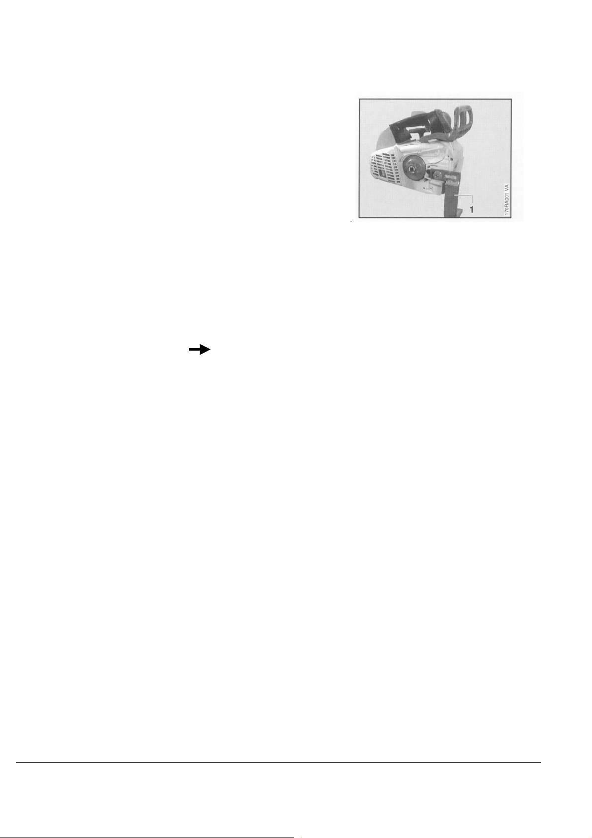
Servicing and repairs are made
considerably easier if the powerhead
is mounted to the assembly stand (1)
5910 890 3100.
This enables the powerhead to be
swivelled to the best position for the
ongoing repair and leaves both hands
free.
It is secured with the bar mounting
stud after removing the chain sprocket
cover and tensioner.
Always use original STIHL
replacement parts. They can be
identified by the STIHL part number,
STIHL
STIHL
the
STIHLSTIHL
parts symbol (The symbol may
appear alone on small parts.
logo and the STIHL
STIHL 019 T 2

2. SPECIFICATIONS
3
2.1 Engine
STIHL single cylinder two-stroke engine with special
impregnated cylinder bore
Displacement:
Bore:
Stroke:
Engine power to ISO 8893:
35.2 cm
40 mm (1.57 in)
28 mm (1.10 in)
1.2 kW (1.6 bhp)
Max. engine speed
with bar and chain:
Idle speed:
Bearings:
12,000 rpm
2,800 rpm
Crankshaft supported in heavyduty ball bearings, needle cages
on small and big ends
Piston pin diameter:
Connecting rod length:
Rewind starter:
Reserve pull on rope rotor:
Starter rope:
8 mm (0.3 in)
51 mm (2 in)
Single pawl system
min. 1/2 turn
3.0 mm (0.12 in) dia.,
800 mm (31.5 in) long
Clutch:
Diameter:
Clutch engages at:
Centrifugal clutch without linings
64 mm (2.52 in)
3,700 rpm
Crankcase leakage test
at gauge pressure:
under vacuum:
0.5 bar (7.25 psi)
0.4 bar (5.8 psi)
(2.15 cu.in)
2.2 Fuel System
Carburetor:
Standard setting
High speed screw H:
Low speed screw L:
Carburetor leakage test
at gauge pressure:
Fuel tank capacity:
Octane number:
Fuel mixture:
Mix ratio:
Air filter:
Diaphragm carburetor
Open approx. 1 turn
Open approx. 1 turn
0.4 bar (4.8 psi)
0.29 1 (0.61 US pt)
min. 90 RON (US/CAN: pump
octane min. 87 unleaded)
Regular brand-name gasoline
and two-stroke engine oil
1:50 with STIHL 50:1 two-stroke
engine oil
25:1 with other brand-name
two-stroke, air-cooled engine oils
Felt element
STIHL 019 T 3

2.3 Ignition System
2.4 Cutting Attachment
2.5 Special Accessories
Type:
Air gap:
Ignition timing:
Spark plug (suppressed):
Electrode gap:
Spark plug thread:
Length of thread:
Oilomatic chain:
Chain sprocket:
Chain speed:
Chain lubrication:
Oil delivery rate:
Oil tank capacity:
Electronic magneto ignition
(breakerless) with integral
trigger unit
0.25 mm (0.010 in)
1.6 - 2.3 mm (0.063-0.091 in)
B.T.D.C. at 8,000 rpm
NGK BPMR 7 A or
CHAMPION RCJ6Y
0.5 mm (0.02 in)
M14x1.25
9.5 mm (0.37 in)
9.32 mm (3/8") Picco-Micro-Mini
7-tooth 3/8" P spur sprocket
21.7 m/s (71.2 ft/sec)
at 10,000 rpm
Speed-controlled reciprocating
oil pump. No oil feed at idle speed
Adjustable 5 - 9 cm
3
/min
(0.17 - 0.30 fl.oz/min)
0.16 l (0.34 US pt)
2.5.1 For User
2.5.2 For Service
STIHL repair kit
6-tooth 3/8" P spur sprocket
8-tooth 1/4" spur sprocket
ElastoStart
Carburetor parts kit
1132 900 5000
1123 640 2005
1123 640 2010
0000 190 3400
1132 007 1060
STIHL 019 T 4

2.6 Tightening Torques
Plastoform screws are used for polymer components and "DG" screws for lightmetal components. These screws form a
permanent thread when they are installed for the first time. They can be removed and installed as often as necessary
without detrimentally affecting the strength of the screwed assembly, providing the specified tightening torque is observed.
For this reason it is essential to use a torque wrench.
Fastener
Spline screw
Spline screw
Spline screw
Spline screw
Spline screw
Spline screw
Spline screw
Spline screw
Collar screw
Spline screw
Collar nut
Plastoform screw
Screw
Use the following procedure when refitting a P or DG screw in an existing thread:
- Place the screw in the hole and rotate it counterclockwise until it drops down slightly.
- Tighten the screw clockwise to the specified torque.
Thread
size
IS-DG 4x20
IS-DG 5x24
IS-DG 5x24
IS-DG 5x24
IS-DG 5x24
IS-DG 5x24
IS-DG 5x24
IS-DG 5x24
IS-DG 8x18
IS-M5x52
M8x1
M12x1 L
M14x1.25
IS-P4x12
IS-DG 3.5x12
For component
Ignition module/cylinder
Handle molding/front handle
Fan housing/engine housing
Engine pan/cylinder
Handle molding/handle
Muffler/cylinder
Spacer flange/cylinder
Engine housing/cylinder
Bar mounting/engine housing
Intake casing/carburetor/flange
Flywheel
Clutch
Spark plug
Hand guard, left/fan housing
Support plate /diaphragm/
spacer flange
Torque
Nm Ibf.ft
Remarks
4.5 3.3
3.5 2.6
4.0 3.0
8.0 5.9
4.0 3.0
7.0 5.2
8.0 5.9
8.0 5.9
16.0 11.8
5.0 3.7
28.0 21.0
50.0 37.0
25.0 18.5
1.7 1.3
2.0 1.5
This procedure ensures that the screw engages properly in the existing thread and does not form a new thread and
weaken the joint.
Note: Power screwdriver speed for use in polymer: Plastoform screws max. 600 rpm,
DG screws max. 500 rpm.
Use only screws specified in parts list.
Do not use screws with underhead locking teeth on polymer components.
STIHL 019 T 5

3. CLUTCH, CHAIN DRIVE, CHAIN BRAKE AND CHAIN TENSIONER
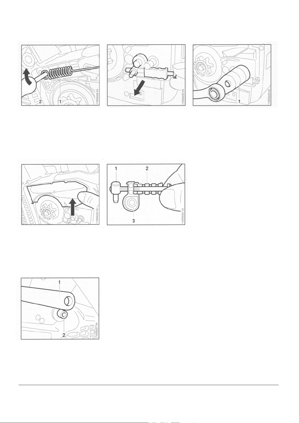
3.1 Chain Sprocket
• Unscrew the nut.
- Pull off the chain sprocket cover.
- Disengage the chain brake by
pulling the hand guard toward
the front handle.
• Remove the E-clip (1).
• Remove the washer (2).
• Take the needle cage out of the
sprocket.
- Clean and inspect the chain
sprocket.
Important: If there are noticeable
wear marks on the inside diameter of
the clutch drum, check its wall
thickness. If it is less than 80% of the
original wall thickness, fit a new
sprocket.
• If the clutch drum is still serviceable,
use No. 120 emery paper or emery
cloth (grain size approx. 120µm) to
clean and roughen its friction
surface.
Reassemble in the reverse sequence.
- Clean stub of crankshaft. Wash
needle cage in clean white spirit and
lubricate with grease - see 11.2.
- Replace damaged needle cage.
- Rotate chain sprocket and apply
slight pressure at the same same
until oil pump drive spring engages
properly.
Note: If the clutch drum has to be
replaced, also check the brake band
- see 3.3.2.
• Pull off the chain sprocket.
STIHL 019 T 6
3.2 Clutch
Troubleshooting chart - see "Standard
Repairs, Troubleshooting" handbook.
- Remove chain sprocket - see 3.1.
3.3 Chain Brake
3.3.1 Checking Function
The chain brake is one of the most
important safety devices on the
chainsaw. Its efficiency is measured in
terms of braking time, i.e. the time that
elapses between activating the brake
and the saw chain coming to a
standstill. The shorter the braking time,
the better the efficiency and protection
offered against being injured by the
rotating chain.
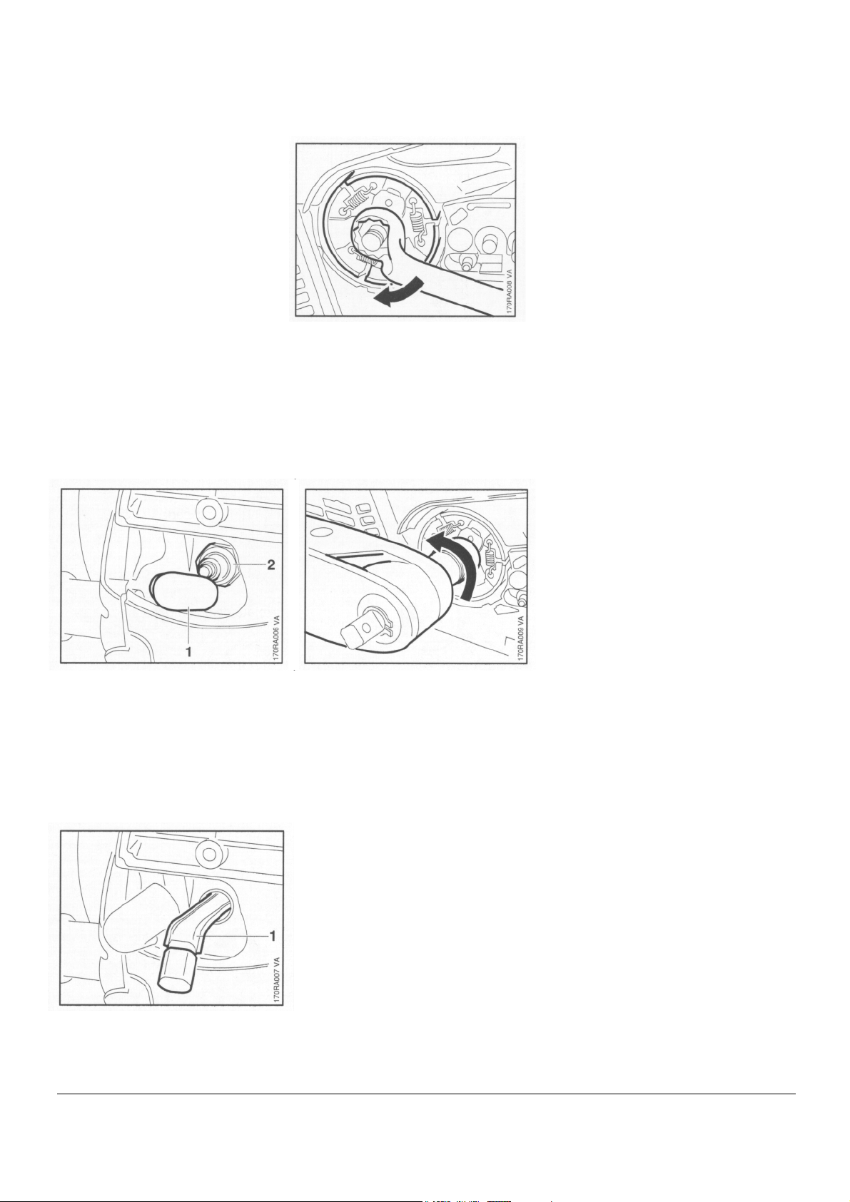
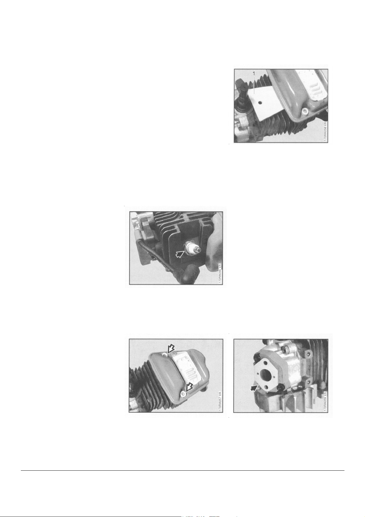
• Pull boot (1) off the spark plug.
- Unscrew the spark plug (2).
• Unscrew the clutch from the
crankshaft in the direction of the
arrow (left-hand thread).
- Disassemble and reassemble
the clutch - see "Standard
Repairs, Troubleshooting"
handbook.
• Screw clutch onto crankshaft
and torque down to 50 Nm
(37 Ibf.ft).
- Remove locking strip from
cylinder.
Contamination (with chain oil, chips,
fine particles of abrasion, etc.) and
smoothing of the friction surfaces of the
brake band and clutch drum impair the
coefficient of friction. This, in turn,
reduces the frictional forces and thus
prolongs the braking time. A fatigued or
stretched brake spring has the same
negative effect.
- Start the engine.
- With the chain brake activated
(locked), open throttle wide for brief
period (max. 3 seconds) the chain
must not rotate.
- With the chain brake released, open
throttle wide and activate the brake
manually - the chain must come to an
abrupt stop.
Note: The braking time is in order if
deceleration of the saw chain is
imperceptible to the eye.
- Install spark plug and torque
down to 25 Nm (18.5 Ibf.ft).
Important: If spark plug has a
separate terminal nut, make sure
that it is properly tightened down.
- Fit spark plug boot.
- Install the chain sprocket see 3.1.
• Push the locking strip (1)
0000 893 5903 into the cylinder.
STIHL 019 T 7
3.3.2 Disassembl
y
- Release tension of brake spring by
pushing the hand guard forwards.
- Remove chain sprocket cover.
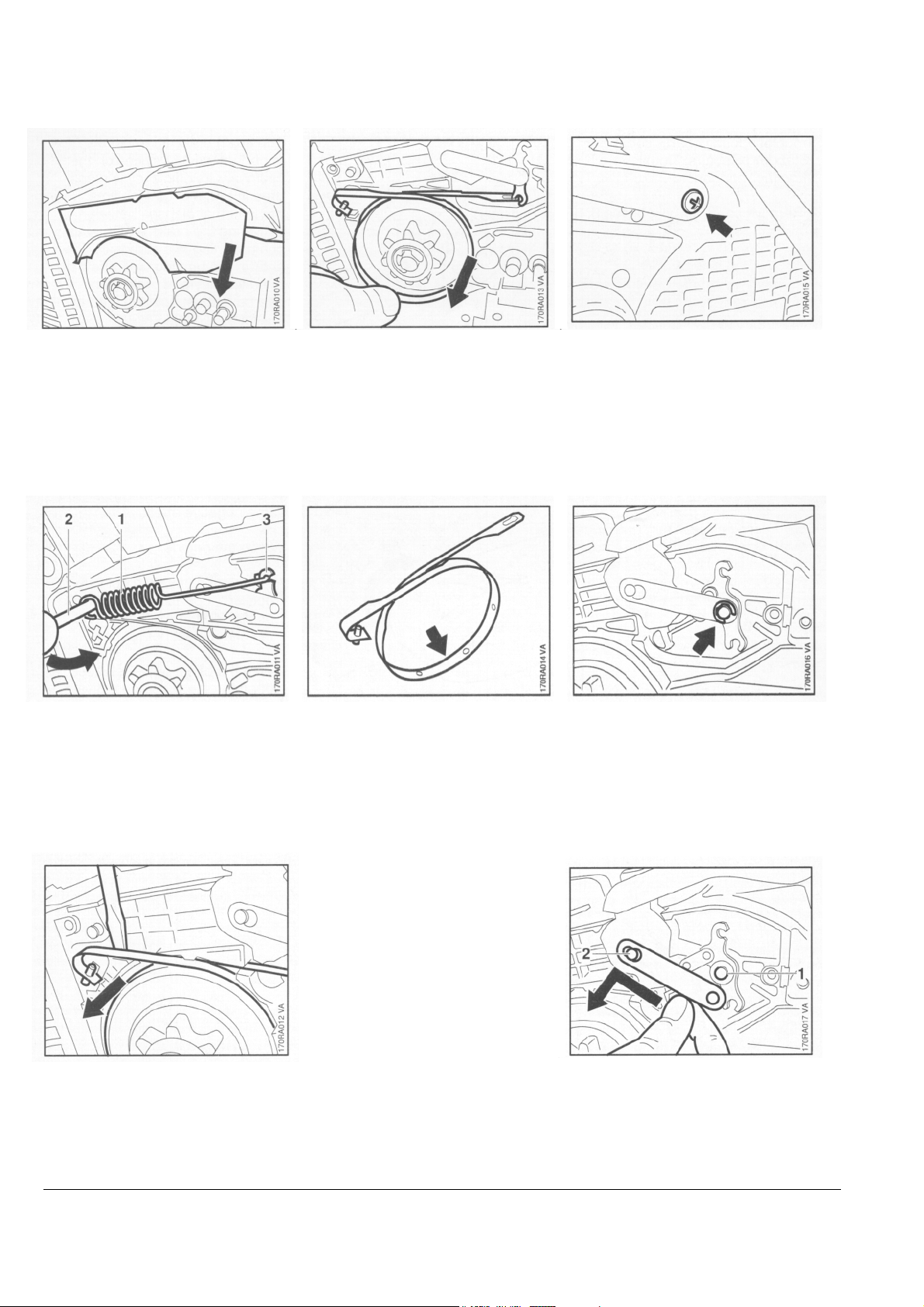
• Ease the cover out of its
retainers.
• Use assembly tool (2)
1117 890 0900 to carefully
disconnect the brake spring (1).
• Unhook the brake spring from
the bell crank (3).
• Remove brake band from the chain
sprocket and detach it from the bell
crank.
Replace the brake band if:
- there are noticeable signs of wear
(large areas on inside diameter
and/or parts of outside diameter) and
- its remaining thickness is less than
0.6 mm (0.024").
• Take out the screw.
- Remove the hand guard from its
seat on the fan housing.
• Remove the E-clip,
Important! Thickness of brake band
must not be less at any point.
• If the brake band is still serviceable,
use No. 120 emery paper or emery
cloth (grain size approx. 120µm) to
clean and roughen its entire friction
surface (inside diameter).
• Lever the brake band out of the
engine housing.
• Slip the strap off the bell crank
pivot pin (1).
• Push the strap to one side and
remove it from the hand guard
pivot pin (2).
STIHL 019 T 8

3.3.3 Assembl
y
• Remove the washer.
- Clean chain brake seat in
housing.
- If the groove of the brake spring
anchor pin is worn, replace the
housing.
- Lubricate sliding and bearing points
of chain brake with STIHL
multipurpose grease or, preferably,
Molykote grease - see 11.2.
- Fit flat spring in position.
• Carefully ease the hand guard
(1) and bell crank (2) off the pivot
pins and lift them away together.
- Pull the bell crank out of the hand
guard.
• Take out the flat spring.
- Inspect parts. Replace any worn or
damaged parts.
• Slide bell crank into end of hand
guard. The short arm of the bell
crank must point to top of hand
guard.
• Locate bearing boss of hand
guard (1) on pivot pin.
- Fit other end over the housing.
STIHL 019 T 9
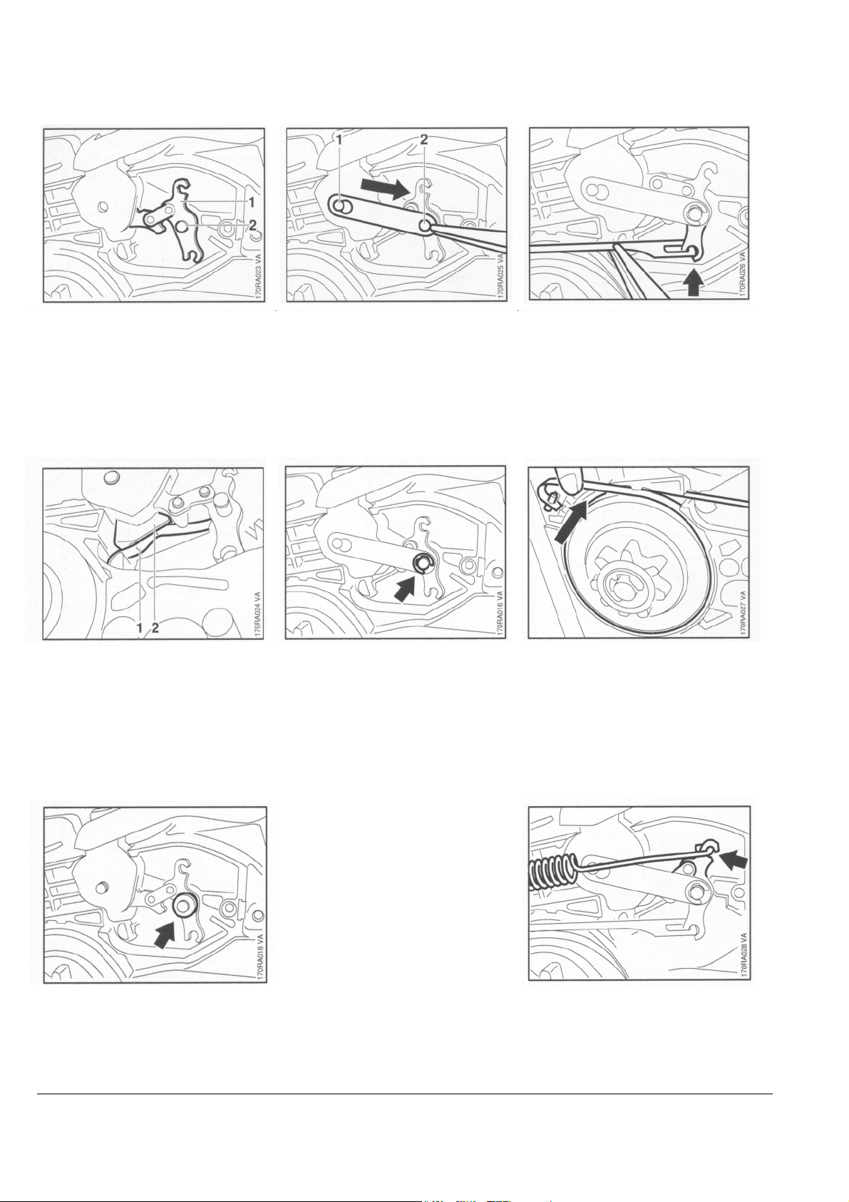
• Position bell crank (1) against
pivot pin (2).
- Push hand guard and bell crank fully
onto the pivot pins.
• Place strap on pivot pin (1) and
pull it in direction of arrow until it
engages the groove.
• Then push it over the pivot pin
(2).
• Attach brake band to the bell
crank.
• Check that flat spring (1)
is properly located on face (2)
of bearing boss.
• Fit the washer.
• Secure strap with E-clip.
- Coat brake band with chain oil
(STIHL Bioplus), see 11.2, to
protect it from corrosion an
cushion "snatching" during the
first few brake applications.
• Fit the brake band and press it
into the engine housing.
• Hook the brake spring onto the bell
crank.
STIHL 019 T 10
3.4 Chain Tensione
r
3.5 Bar Stud
• Use the assembly tool (2)
1117 890 0900 to attach the
brake spring (1) to the anchor
pin.
• Push cover over chain brake until
it snaps into position and then tap
it home carefully with a plastic
mallet.
- Remove the chain sprocket cover.
• Pull the cover out of the engine
housing.
• Unscrew the nut (1) from the
adjusting screw (2).
• Take the adjusting screw out of the
cover (3).
- Remove the chain sprocket cover.
• Push the stud puller (1)
5910 893 0501 onto the stud as far
as it will go.
• Unscrew the stud.
- Insert stud and torque down to
16 Nm (11.8 Ibf.ft).
Reverse the above sequence to
install the chain tensioner.
• Fit hand guard (1) over boss (2)
on the fan housing.
- Insert screw and tighten to
1.7 Nm (1.25 Ibf.ft).
STIHL 019 T 11
4. ENGINE
4.1 Disassembly
Always check and, if necessary, repair
the fuel system, carburetor, air filter
and ignition system before looking for
faults on the engine.
Troubleshooting chart - see "Standard
Repairs, Troubleshooting" handbook.
- Remove the clutch - see 3.2.
- Take the locking strip out of the
cylinder.
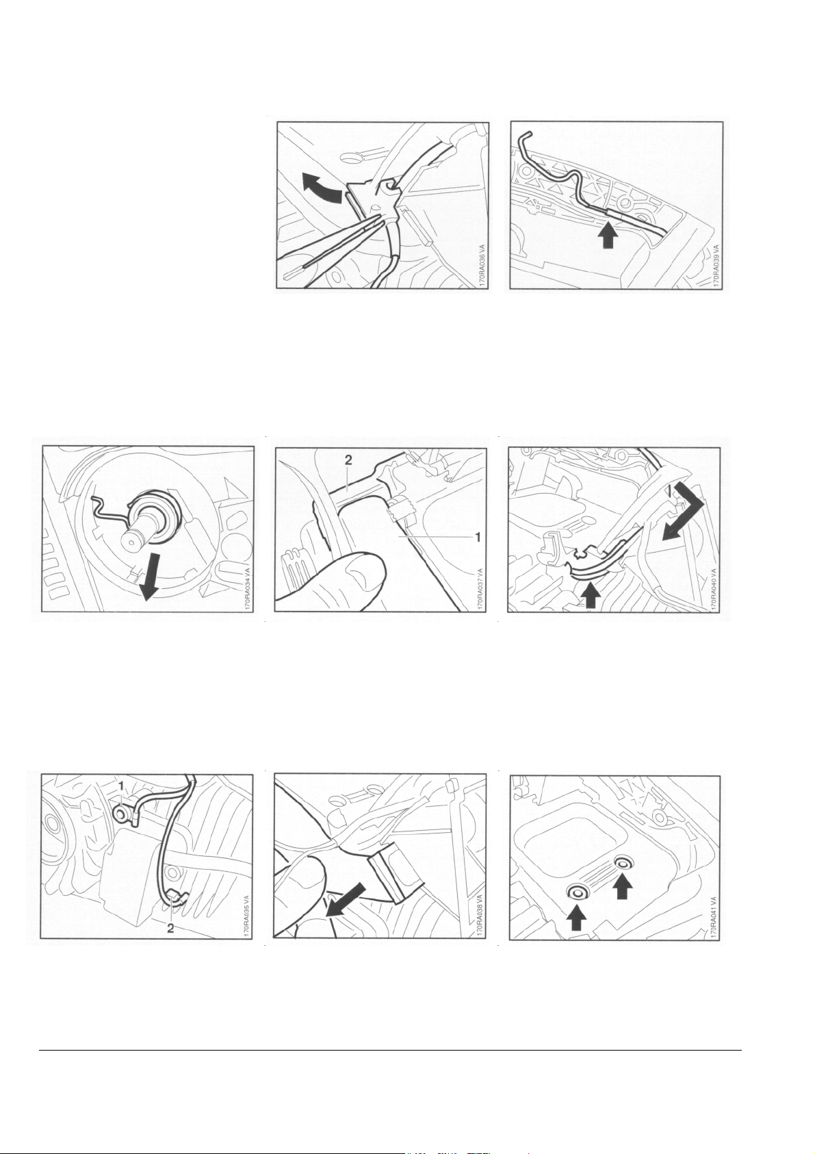
• Open the grommet. • Take throttle cable out of retainer.
• Pull off the worm with drive spring.
- Remove throttle trigger - see 8.1.
• Take out the upper screw (1).
• Disconnect the short circuit wire (2).
• Pull intake pipe (1) out of the
intake casing (2).
• Pull intake pipe with grommet out
of engine housing.
- Remove the grommet.
• Remove throttle cable from
grommet and pull it downwards
and out of the handle.
• Take out screws from top of
engine.
STIHL 019 T 12
4.2 Assembly
• Take out screws from underside of
engine.
• Remove engine sideways from
housing.
• Check that grommet is properly
seated in the engine housing.
• Throttle cable sleeve must locate in
retainer in air baffle.
• Place throttle cable in the
grommet.
- Fit top and bottom engine
mounting screws and torque
down to 8.0 Nm (5.9 Ibf.ft).
• Push grommet, ledge facing up,
over the lugs of the intake pipe.
• Fit engine and position throttle
cable in the handle at the same
time.
- Push throttle cable into retainer in
handle.
• Push grommet with intake pipe into
the engine housing until the ledge
butts against the engine housing.
STIHL 019 T 13
r
4.3 Exhaust Muffler/Spark Arresting Screen
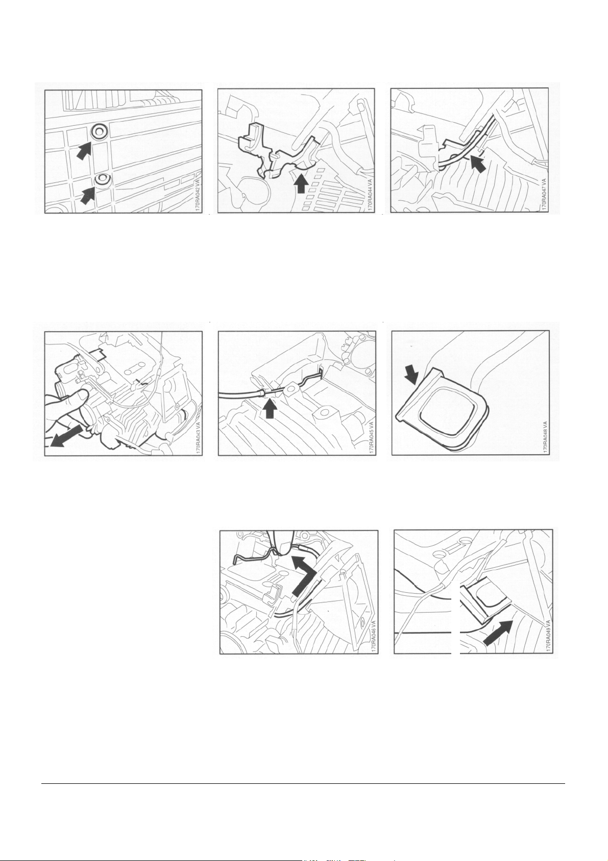
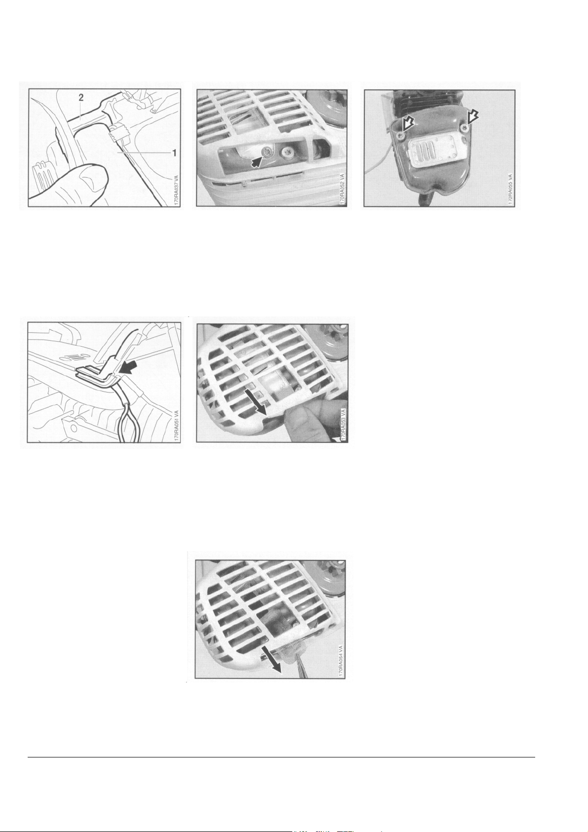
• Fit the intake pipe (1) in the
intake casing (2).
• Fit the short circuit and ground
wires (pull them downward and out
of handle as far as possible) in the
grommet and close the grommet.
Spark arresting screen
• Take out the screw.
• Remove the cover plate.
Muffle
- Remove the engine - see 4.1.
• Take out the screws.
- Remove the muffler.
Reassemble in the reverse
sequence.
- Tighten screws to 7.0 Nm
(5.2 Ibf.ft).
- Install the engine - see 4.2.
- Connect short circuit and ground
wires to ignition module.
- Fit throttle trigger - see 8.1.
- Fit the worm with drive spring in
position.
- Install the clutch - see 3.2.
• Remove the spark arresting screen.
- Clean the spark arresting screen or
fit a new one if necessary.
STIHL 019 T 14
4.4 Leakage Test
4.4.1 Preparations
Defective oil seals, diaphragms and
gaskets or cracks in castings or the
spacer flange cause leaks. Such
faults allow supplementary air to
enter the engine and thus upset the
fuel-air mixture.
This makes adjustment of the
prescribed idle speed difficult, if not
impossible.
Moreover, the transition from idle
speed to part or full throttle is not
smooth.
The engine housing can be checked
thoroughly for leaks with the
carburetor and crankcase tester and
the vacuum pump.
- Remove the carburetor - see 1 0.5.2.
- Set the piston to top dead center
(T.D.C.). This can be checked
through the spark plug hole.
- Remove the air baffle - see 10.6.
• Fit the sealing plate (1)
0000 855 8106 between muffler
and cylinder.
Note: The sealing plate must
completely cover the exhaust port.
- Tighten the screws moderately.
Important: Do not overtighten the
screws since the sealing plate may
otherwise be damaged.
• Fit the spark plug and tighten
down to 25 Nm (18.5 Ibf.ft).
• Back off muffler mounting screws
halfway.
• Fit new gasket on spacer flange.
STIHL 019 T 15
 Loading...