

Page 1

TABLE TENNIS TABLE
MODEL NO.
T8523
O W N E R ' S M A N U A L
1. Read this manual carefully before starting assembly. Read each step completely before beginning
each step.
2. Some smaller parts may be shipped inside larger parts. Check inside all parts and cartons
before assembling or ordering parts.
3. To make assembly easier, use the Hardware Identifier on page 7 to identify and sort all
fasteners. Check all cartons for kits. All hardware may not be located in one kit.
4. Do not tighten hardware until instructed to do so. If hardware is tightened too soon, mounting holes
may not align and parts may not easily fit together. Leave locknuts slightly loose until you are instructed to
tighten them.
5. Tools required for assembly: Phillips Screwdriver, Two 9/16” Wrenches, One 3/8” Wrench.
Note: Adjustable wrenches can be substituted for wrenches.
6. Save this instruction manual and your proof of purchase (receipt) in the event that the
manufacturer has to be contacted for replacement parts.
Please Do Not Return This Product To The Store!
Contact Escalade® Sports customer service department at:
Phone: 1-866-873-3528 Toll – Free !
Fax: 1-866-873-3533 Toll – Free !
E-mail: tabletennis@escaladesports.com
Mailing Address (correspondence only):
Escalade Sports
PO Box 889
Evansville, IN 47706
Please visit our World Wide Web site at: www.escaladesports.com
ON-LINE TROUBLE SHOOTING TECHNICAL ASSISTANCE
ON-LINE PARTS REQUESTS FREQUENTLY ASKED QUESTIONS
®
ADDITIONAL ESCALADE
SPORTS PRODUCT INFORMATION
2L-4138-00
Escalade® Sports products may be manufactured and/or licensed under the following patents.
6120397, 5816957, 5769744, 5119741, 4911085, 4717157, D460140, D420563
Additional patents may be pending. One or more of the listed patents and/or pending patents may cover specific product.
2012 Escalade Sports
Page 2

AT LEAST TWO ADULTS ARE NEEDED TO COMPLETE THE ASSEMBLY!
CAUTION:
1. Open the hardware kit and sort all the hardware. For your help
in identifying hardware, see the hardware identifier on page 7.
2. Insert one Caster without Brake #11 and one Caster with Brake
#12 into Caster Beam #14. Be sure casters are inserted all the
way into caster beam. Assemble both caster beams and casters
the same way. See Figure 1.
3. Attach two Upright Tubes #15 to each Caster Beam #14 using
two Carriage Bolts #28, two washers #29 and two locknuts
#26 in each tube. See Figure 2. Tighten nuts but do not
overtighten, cracking the plastic.
4. Attach one Safety Latch #19 in the right hand hole of a Name
Panel #17 as shown in Figures 3 and 3A. Attach with one screw
#24, one washer #25 and one locknut #23. NOTE: Safety
latch must be installed exactly as shown, with flange
on safety latch over top of name panel.
IMPORTANT: Do not overtighten locknuts. Latches #19 must
pivot freely. When latch is pivoted, it must freely fall back
to original position when released.
DO NOT LEAVE TA BLE UNATTENDED UNTIL A SSEMBLY IS
COMPLETE!
Figure 1
Assemble the other safety latch #19 to the other name
panel #17 in exactly the same way.
CAUTION:
INSTALL SAFETY LATCHES EXACTLY AS
SHOWN. DO NOT SKIP THIS STEP. DO NOT
OPERATE TABLE WITHOUT SAFETY LATCHES
INSTALLED.
Figure 2
Figure 3
Figure 3A
2
Page 3
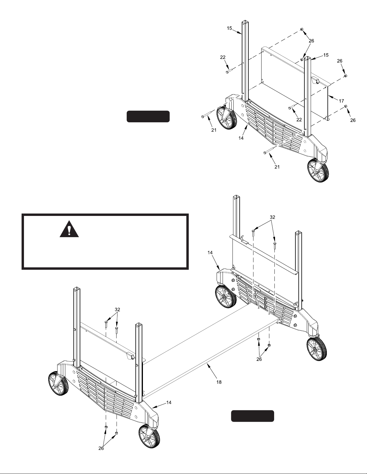
5. Attach Name Panel #17 to inside of Upright Tubes #15 using
two bolts #21, two bolts #22, and four locknuts #26. See
Figure 4. Short bolts #22 go in top holes and long bolts #21 go
in bottom holes. Tighten top bolts #22 but do not overtighten,
crushing tubes. Do not tighten bottom bolts #21 tight yet,
they will have to be removed in a later step.
6. Repeat step 5 with other name panel and caster beam with upright
tubes. See Figure 4.
Figure 4
7. Attach Wood Bottom Board #18 to Caster Beams #14 as shown
in Figure 5. Attach with four bolts #32 and four locknuts #26.
Tighten locknuts #26 but do not overtighten, cracking plastic.
See Figure 5.
CAUTION:
AT LEAST TWO ADULTS ARE NEEDED TO
COMPLETE THE REMAINDER OF THIS
ASSEMBLY!
Figure 5
3
Page 4
CAUTION:
AT LEAST TWO ADULTS ARE NEEDED TO COMPLETE THE
FOLLOWING STEPS!
4
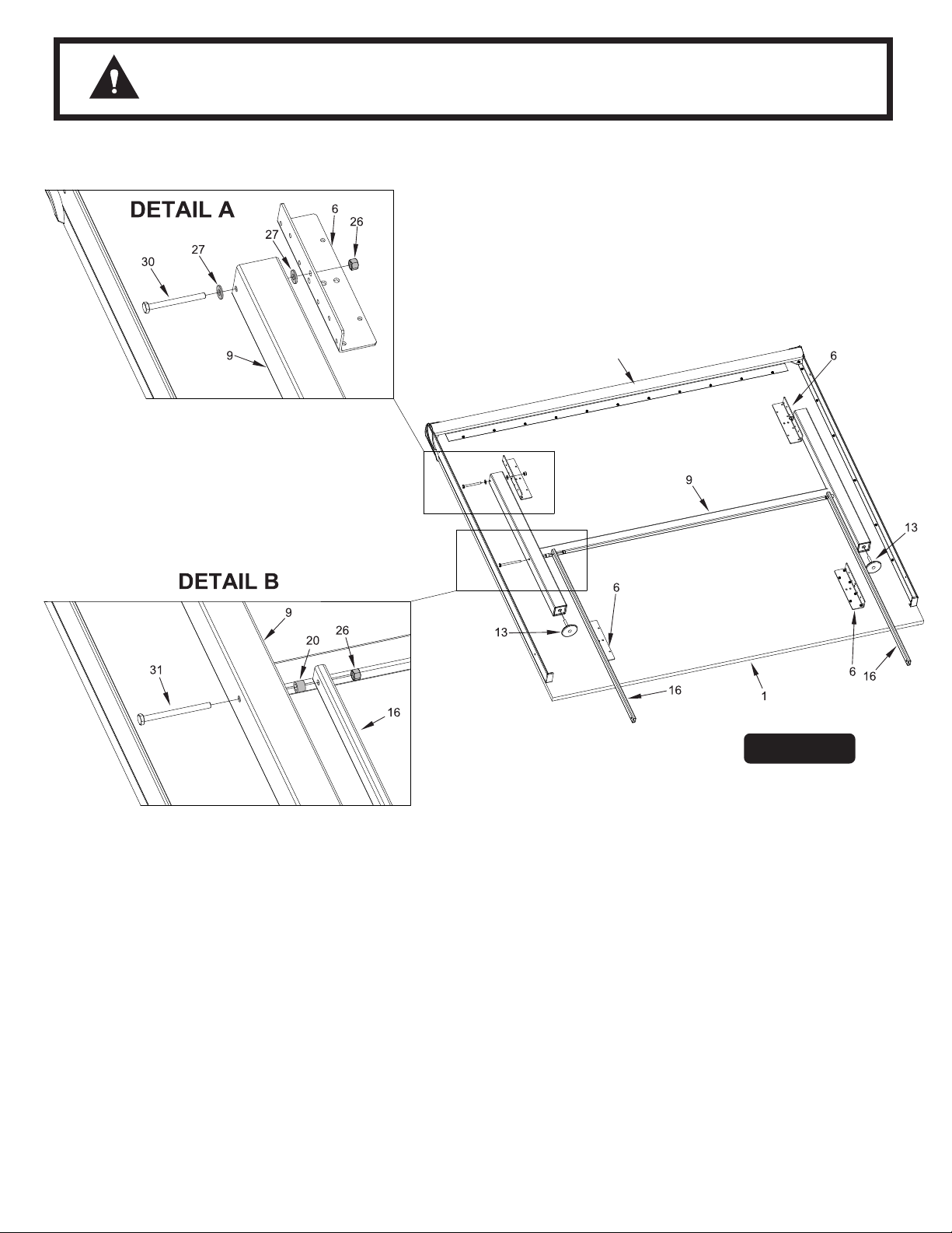
8. When doing this step, you may want to place a towel between
table top and wall to keep from scratching wall. With the help of
at least one other adult, take either table half #1 and lean it
against a wall as shown in Figure 6. Turn top so that it is positioned
as shown.
NOTE: If you desire, table can be placed on the floor, if
carpeted, or on the shipping carton, with the playing
surface down. Be careful not to damage the playing
surface.
9. Attach Leg Assembly #9 to Brackets #6 on the bottom of table
half #1. See Figure 6 and Detail A. Use two bolts #30, four
washers #27 and two locknuts #26.
go on both sides of leg. NOTE: Cross Brace on Leg
Assembly goes against table.
Tighten locknuts snug, but do not overtighten. Leg must pivot in
brackets.
NOTE: Washers #27
Figure 6
10. Screw a Leg Leveler #13 into end of each leg on leg assembly
#9. See Figure 6.
11. Attach Linkages #16 to inside
Spacers #20 and Locknuts #26. NOTE: Spacer #20 goes
between leg and linkage. See Figure 6 and Detail B.
Tighten locknuts snug, but do not overtighten. Joint must be
able to move.
12.
You are now done assembling parts to the first table half.
Repeat steps 8 – 11 on second table half.
4
of legs #9 using bolts #31,
Page 5
CAUTION:
UNTIL THE TABLE HALVES ARE CONNECTED THEY WILL NOT STAND ON THEIR
OWN. IT IS RECOMMENDED TO HAVE THREE PEOPLE TO CONNECT TABLE
HALVES. TWO TO STABILIZE TABLE AND ONE TO BOLT TABLE TOGETHER.
1
27
22
15
6
26
15
9
16
20
26
Figure 7
16
21
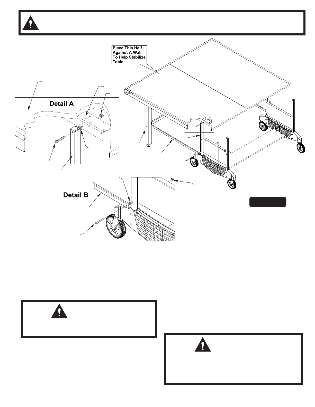
13. Place a Hex Bolt #22, a Washer #27 and a Locknut #26 on
the floor next to all four caster wheels on both sides of base
assembly you put together earlier.
14. Make sure the leg assembly #9 on the first table half is open
and linkages #16 are pointing toward middle of table. See
Figure 7. With one adult person on each side of the table, lift
and set table half on its legs.
CAUTION:
TABLE HALF WILL NOT STAND ON ITS OWN,
YOU MUST HOLD IT UP!
Brace table half against a wall to help stabilize it. Be sure that
there is enough room to connect second half.
While holding table half up, pull the base assembly under this
half until the hole in Upright Tube #15 is aligned with lower
middle
table half. See Figure 7 and Detail A. Attach Upright Tubes
#15 to Mounting Brackets #6 with Hex Bolts #22, Washers
#27 and Locknuts #26 that you placed on floor in step 13.
15. Remove bottom bolts #21 from bottom holes that attach name
panels to Upright Tubes. Attach end of Linkage #16 to outside
of Upright Tube #15 with bolt #21 (that you just removed),
spacer #20 and Locknut #26. Note spacer #20 goes between
linkage #16 and upright tube #15. See Figure 7 and Detail
B. Tighten all nuts snug, but do not overtighten. Joints must
pivot.
hole in the Mounting Bracket #6 on the bottom of
CAUTION:
DO NOT ATTEMPT TO RAISE THIS HALF UP TO
STORAGE POSITION UNTIL OTHER HALF TOP
IS ATTACHED AND YOU HAVE READ AND
UNDERSTAND ALL OPERATING INSTRUCTIONS.
5
Page 6
CAUTION:
AT LEAST TWO ADULTS ARE NEEDED TO COMPLETE THE
FOLLOWING STEPS!
1
15
20
22
6
27
26
26
16
Figure 8
16
9
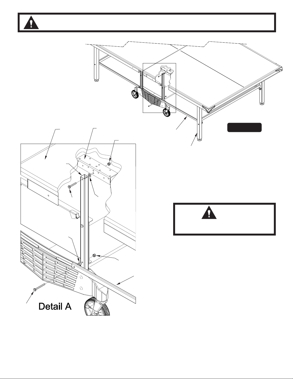
16. With first table half (that you just attached) braced against a
wall, attach second table half.
Make sure the leg assembly #9 on the second table half is
open and linkages #16 are pointing toward middle of table.
See Figure 8. With one adult person on each side of the table,
lift and set table half on its legs.
CAUTION:
TABLE HALF WILL NOT STAND ON
ITS OWN, YOU MUST HOLD IT UP!
While holding table half up, slide this half toward base assembly
until the hole in Upright Tube #15 is aligned with lower middle
hole in the Mounting Bracket #6 on the bottom of table half.
See Figure 8 and Detail A. Attach Upright Tubes #15 to Mounting
Brackets #6 with Hex Bolts #22, Washers #27 and Locknuts
#26 that you placed on floor in step 13.
21
17. Remove bottom bolts #21 from bottom holes that attach name
panels to Upright Tubes. Attach end of Linkage #16 to outside
of Upright Tube #15 with bolt #21 (that you just removed),
spacer #20 and Locknut #26. Note spacer #20 goes between
linkage #16 and upright tube #15. See Figure 8 and Detail
A. Go back over assembly and tighten all nuts snug,
but do not overtighten. Joints must pivot.
Congratulations! You have completed assembly of your new
Table Tennis Table. Please read and understand the Opening
and Closing Instructions before using your table.
6
Page 7

TO LEVEL TABLE IN PLAYING POSITION
You can raise, or lower, outer ends of table by screwing the leg
levelers #13 in to lower or out to raise. See Figure 9.
Figure 9
7
Page 8

OPENING AND CLOSING INSTRUCTIONS
READ OPERATING INSTRUCTIONS CAREFULLY BEFORE OPERATING TABLE!
DO NOT ALLOW CHILDREN TO OPEN TABLE! DO NOT CLIMB, STAND OR
CAUTION:
JUMP ON TABLE! SERIOUS OR FATAL INJURY MAY RESULT! THIS IS NOT A
TOY! TABLE IS TO BE OPENED OR CLOSED BY ADULTS ONLY! FAILURE TO
COMPLY WITH OPENING AND CLOSING INSTRUCTIONS COULD RESULT
IN PERSONAL INJURY OR PROPERTY DAMAGE.
TO OPEN:
1. Stand behind the table near the safety latch.
2. Hold table half with one hand and pivot safety latch enough to
allow the edge of the table half to pass over it.
3. While keeping an eye on the safety latch, pivot table half until it
moves past the safety latch. Once edge of table has passed over
safety latch, stop pivoting table half.
4. With both hands on the table half, center yourself along the table
half and lower the table half to the floor.
5. Repeat for the other table half.
TO CLOSE:
1. Lift table half upward and inward to vertical position.
2. Check to be sure that table half is locked in the safety latch.
3. Repeat for the other table half.
CAUTION
THIS IS A GAME TABLE. DO NOT SIT, STAND, LEAN, WALK
OR JUMP ON TABLE! FAILURE TO COMPLY WITH THIS
CAUTION COULD RESULT IN PERSONAL INJURY AND/
OR PROPERTY DAMAGE!
8
Page 9

ONE YEAR LIMITED WARRANTY
This consumer warranty extends to the original consumer purchase of any ESCALADE® SPORTS Product
(hereinafter referred as the "Product").
WARRANTY DURATION: This Product is warranted to the original consumer purchase of a period of one (1) year from the original
purchase.
WARRANTY COVERAGE:ESCALADE SPORTS warrants to the original Consumer Purchaser that any Product of its manufacture is free from
defects in material and workmanship when used for the intended purpose under normal use and conditions. THIS WARRANTY IS VOID IF THE
PRODUCT HAS BEEN DAMAGED BY ACCIDENT, UNREASONABLE USE, NEGLIGENCE, IMPROPER SERVICE, FAILURE TO FOLLOW INSTRUCTIONS PROVIDED WITH THE PRODUCT OR OTHER CAUSES NOT ARISING OUT OF DEFECTS IN MATERIAL AND WORKMANSHIP.
WARRANTY PERFORMANCE: During the above one (1) year warranty period, ESCALADE SPORTS shall repair or replace with a
comparable model, and Product, or component thereof, which may prove defective under normal use and proper care, and which our
examination shall disclose to our satisfaction to be thus defective, please contact our Warranty Dept.
1-866-873-3528 / W
arranty Dept.
Or Write us at:
Escalade® Sports, Inc. - P.O. Box 889, Evansville, IN 47706 - Attn: Warranty Dept.
Or E-mail us at:
customerservice@escaladesports.com
Other than shipping requirements no charge will be made for such repair or replacement of in-warranty Products. ESCALADE® SPORTS
strongly recommends that the Product is insured for value prior to mailing.
WARRANTY DISCLAIMERS: ANY IMPLIED WARRANTIES ARISING OUT OF THIS SALE, INCLUDING BUT NOT LIMITED TO THE
IMPLIED WARRANTIES OF MERCHANTABILITY AND FITNESS FOR A PARTICULAR PURPOSE, ARE LIMITED IN DURATION TO THE
ABOVE ONE (1) YEAR WARRANTY PERIOD. ESCALADE® SPORTS SHALL NOT BE LIABLE FOR LOSS OF USE OF THE PRODUCT OR
OTHER CONSEQUENTIAL OR INCIDENTAL COSTS, EXPENSES OR DAMAGES INCURRED BY THE CONSUMER OF ANY OTHER USE.
Some states do not allow the exclusion or limitation of implied warranties or consequential or incidental damages, so the above
limitations or exclusions may not apply to you.
LEGAL REMEDIES: This warranty gives you specific legal rights and you may also have other rights which may vary from state to state.
CARE AND MAINTENANCE
You have purchased a quality product that will give you years of enjoyment. By following these simple maintenance steps, you will add to the life of your new table.
THE TABLE TOP
The top (playing surface) of your table is made of particle board or MDF. Like all products made of wood, it can be affected by atmospheric changes in both temperature and
humidity. This may cause a slight sag or distortion as the top expands or contracts. This is normal and should not cause concern as it does not detract from the play or utility value
of the table. After assembly of the table, you can minimize the effects of temperature and humidity changes by storing the table in the folded up position in a dry area when table
is not in use.
STORAGE OF YOUR TABLE
This table must be stored indoors to prevent damage to the playing surface. Dampness and extreme temperature changes can cause the wood to warp, swell, crack or blister.
When your table is not in use, it should be folded up in a dry area. Due to the nature of particle board, table top may bow. Damp and humid conditions will amplify this. This is
normal and will not affect playability of table.
CLEANING YOUR TABLE
To clean your table use a soft, damp (NOT WET) cloth only. To prevent damage to your table's playing surface, DO NOT USE ANY CHEMICALS, ABRASIVE OR CLEANING
PRODUCTS on your table's playing surface.
MAINTENANCE OF YOUR TABLE
Be sure to oil all moving parts of your table including the pivot points. This will insure the safety and ease of use of your table.
This table must be kept indoors to prevent damage to the playing surface. Dampness and extreme temperature changes which occur on patios or similar areas can cause wood
to warp, swell, crack or blister.
UNLEVEL FLOORS
If table does not seem level, it is probably due to uneven or unlevel floors. Set the table in its PLAYING POSITION and move table several inches in different directions to find the
best location for the table then use leg levelers provided to level table. If the floor is extremely unlevel, table may not play or operate properly.
9
Page 10

PRODUCT PARTS LIST - T8523
Item No. Part No. Description Qty. Item No. Part No. Description Qty.
1
2
3
4
5
6
7
8
9
10
11
12
13
14
15
16
17
4A-5532-00
2S-4644-05
2S-4645-05
2S-5136-01
1B-4082-99
2S-6139-01
3M-1027-00
3M-4165-00
1A-7001-02
7B-6404-00
2Q-4031-00
2Q- 4032-00
2Q-4028-00
3M-6839-01
8S-6783-02
8S-6506-03
2S-6422-28
Table Half Top
Side Rail - Right Hand
Side Rail - Left Hand
Ball Holder / End Rail
#8 x 9/16 Sheet Metal Screw
Mounting Bracket
End Plug (for the End Rail)
Corner Protector
Leg Assembly
2 x 2 Leg Insert - 5/16-18 Threads
5" Caster
5" Caster With Brake
5/16-18 Leg Leveler
Molded Caster Beam
Upright Tube
Linkage
Name Panel
2
2
2
2
122
8
4
4
2
4
2
2
4
2
4
4
2
18
19
20
21
22
23
24
25
26
27
28
29
30
31
32
33
34
2W-7641-01
2S-6496-02
7B-6161-02
WB-1075-02
WB-1094-02
WB-1007-02
1B-4049-01
2N-0214-02
2B-4047-02
2B-6087-02
1B-6117-00
2N-0109-02
1B-6191-02
1B-6477-02
1B-6475-02
5A-4276-00
2L-4138-00
Wood Bottom Board
Safety Latch
Plastic Spacer
1/4-20 x 2 1/4 Hex Head Bolt
1/4-20 x 1 1/2 Hex Head Bolt
#10-24 Locknut
#10-24 x 3/4 Phillips Round Head Screw
#10 Burr Washer
1/4-20 Locknut
Nylon Washer
1/4-20 x 2 Carriage Bolt
1/4 Washer
1/4-20 x 2 3/4 Hex Head Bolt
1/4-20 x 3 1/4 Hex Head Bolt
1/4-20 x 1 1/4 Hex Head Bolt
Clipper Net & Post Set
Owners Manual
1
2
8
4
8
2
2
2
32
12
8
8
4
4
4
1
1
10
2L-4138-00
Page 11

MESA DE TENIS
NÚMERO DE MODELÓ
T8523
M A N U A L D E L U S U A R I O
1. Lea este manual cuidadosamente antes de empezar a ensamblar. Lea completamente cada uno de los
pasos antes de empezar cada paso.
2. Algunas partes pequeñas pueden ser empacadas dentro de las partes grandes. Verifique en el interior
de todas las partes y cartones antes de ensamblar o solicitar partes.
3. Para que el ensamblado le sea más fácil, utilice la lista de partes de la página 7 para la identificación y
clasificación de las partes y sus componentes. Busque los juegos de tornillos en todos los cartones.
Todos los tornillos y sus componentes no se encuentren en un sólo juego.
4. No ajuste las partes hasta que las instrucciones se lo indiquen. Si las partes se ajustan antes de lo indicado,
es posible que los orificios no queden alineados, resultando que las partes queden fuera de su lugar y fácilmente no
coincidan. Deje las tuercas de seguridad levemente flojas hasta que las instrucciones le indiquen ajustarlas.
5. Herramientas necesarias: Desarmador Phillips, dos llaves de 9/16” y dos llaves de 3/8” (Puede utilizar una llave
ajustable en vez de llaves).
6. Guarde estas instrucciones y recibo de pago en el evento que el fabricador deba de ser contactado
para partes de remplazo.
Por favor NO devuelva este producto a la tienda!
Contacte el departamento de servicio al cliente de Escalade® Sports:
Teléfono: 1-866-873-3528 ¡Sin costo alguno!
Fax: 1-866-873-3533 ¡Sin costo alguno!
Correo Electronico: tabletennis@escaladesports.com
Apartado postal (sólo para correspondencia):
Escalade Sports
PO Box 889
Evansville, IN 47706
Visite nuestra página Web internacional: www.escaladesports.com
SOLUCION DE PROBLEMAS POR INTERNET ASISTENCIA TÉCNICA
PEDIDO DE PARTES POR INTERNET PREGUNTAS FRECUENTES
MÁS INFORMACIÓN SOBRE PRODUCTOS DE ESCALADE® SPORTS
2L-4138-00
Los productos Escalade® Sports se pueden fabricar y/o producir bajo las siguientes patentes.
6120397, 5816957, 5769744, 5119741, 4911085, 4717157, D460140, D420563
Puede haber patentes en trámite. Una o más patentes mencionadas y/o en trámite pueden cubrir productos específicos.
2012 Escalade Sports
Page 12

CUIDADO: SE REQUIEREN POR LO MENOS DOS ADULTOS PARA
PRECAUCIÓN
1. Abra el Juego (Conjunto) del hardware y clasifique todos los Tornillos
y Tuercas. Consulte el identificador de hardware (tornillos y tuercas) en
la página 7 para que le ayude y pueda identificar los tornillos y
tuercas.
2. Inserte una Llanta sin Seguro #11 y una Llanta con Seguro #12 en el
Carril con Llantas #14. Asegúrese que las llantas estén insertadas
completamente en el Carril con Llantas. Ensamble ambos Carriles con
Llantas y las llantas de la misma manera. Vea la Figura 1.
3. Coloque dos Tubos Verticales #15 a cada Carril con Llantas #14
usando dos Tornillos de Carruaje #28, dos rondanas #29 y dos
Tuercas de seguridad #26 en cada tubo. Vea la Figura 2. Apriete
las tuercas pero no las sobreapriete para no estrellar el
plástico.
4. Coloque un pasador de seguridad #19 en el orificio derecho del
Placa con nombre #17 con un tornillo #24 una rondana #25 y una
tuerca de seguridad #23 como se muestra en las Figuras 3 y 3A.
NOTA: El pasador de seguridad debe de instalarse
exactamente como se muestra, con la PESTAÑA de el
pasador de seguridad sobre la superficie del Placa con
nombre
IMPORTANTE: No sobreapriete las tuercas de seguridad. Los pasadores
de seguridad #19 deben de girar libremente. Cuando el pasador este
girado, este debe de regresarse libremente a su posición original
cuando sea soltado.
COMPLETAR EL ENSAMBLADO! NO DEJE LA MESA DESATENDIDA
HASTA QUE HAYA FINALIZADO EL ENSAMBLADO!
Figura 1
Ensamble el otro pasador de seguridad #19 al otro Placa con nombre
#17 exactamente de la misma manera.
PRECAUCIÓN
INSTALE LOS PASADORES DE SEGURIDAD
EXACTAMENTE COMO SE MUESTRA. NO OMITA
ESTE PASO. NO UTILICE LA MESA SIN LOS
PASADORES DE SEGURIDAD INSTALADOS.
Figura 2
VISTA SUPERIOR
Figura 3
EL PASADOR DE
SEGURIDAD #19 DEBE
ESTAR INSTALADO COMO
SE MUESTRA CON LA
PESTAÑA Y EL PASADOR
SOBRE LA SUPERFICIE
DEL PLACA CON NOMBRE!
Figura 3A
2
Page 13

5. Coloque el Placa con nombre #17 en el interior de los tubos
verticales #15 utilizando dos tornillos #21, dos tornillos #22, y 4
tuercas de seguridad #26. Vea Figura 4. Los tornillos cortos #22
van en los orificios superiores y los tornillos largos #21 van en los
orificios inferiores. No apriete los tornillos #21 todavía, los
va a tener que remover luego.
6. Repita el paso 5 con, la otra Placa y el Carril con Llantas con los
Tubos Verticales. Vea la Figura 4.
Figura 4
7. Coloque la Tabla Inferior de Madera #18 al carril con llantas #14
utilizando los tornillos #32 y las cuatro (4) tuercas de seguridad #26
como se muestra en la Figura 5. Apriete las tuercas de seguridad #26
pero no las sobre apriete para no estrellar el plástico. Vea la Figura 5.
PRECAUCIÓN
SE REQUIEREN POR LO MENOS DOS
ADULTOS PARA TERMINAR EL RESTO DEL
ENSAMBLADO!
Figura 5
3
Page 14

PRECAUCIÓN:
DETALLE A
¡POR LO MENOS SE REQUIERE DE DOS ADULTOS PARA
COMPLETAR LOS SIGUIENTES PASOS!
4
DETALLE B
8. Cuando realice este paso, es posible que desee colocar una
toalla entre el tablero y la pared para no rayar la pared. Con la
ayuda de al menos de otro adulto, tome una de las mitades de
la Mesa # 1 y apóyela contra una pared, como se muestra en
la Figura 6. Gire el tablero para que este sea colocado como
se muestra
NOTA: Si se desea, puede colocar la mesa en el suelo si está
alfombrado o sobre la caja de cartón del empaque, con la
superficie de juego hacia abajo. Tenga cuidado de no dañar
la superficie de juego
9. Coloque la Pata Ensamblada #9 a los Soportes de Escuadra #6
en la parte inferior de la mitad de la mesa #1, utilizando dos
tornillos #30, cuatro rondanas #27 y dos tuercas de seguridad
#26. Vea la Figura 6 y el Detalle A.
van en ambos lados de las pata. NOTA: la barra soldada
en las patas #9 va en contra de la mesa.
NOTA: Rondanas #27
Figura 6
10. Atornille el Nivelador de la Pata # 13 en el extremo de cada
pata ensamblada # 9. Vea la Figura 6.
11. Coloque los Tubos Conectores #16 en el interior de las
patas #9 utilizando los tornillos #31, los Separadores #20
y las Tuercas de Seguridad #26. NOTA: Los
Separadores #20 van entre las patas y los tubos
conectores. Vea la Figura 6 y el Detalle B. Apriete las
tuercas de seguridad ajustándolas, pero no las sobre
apriete. Ya que la unión debe ser capaz de moverse.
12. Ya ha terminado de ensamblar las partes a la primera mitad
de mesa. Repita los pasos del 8 al 11 a la Segunda mitad.
Apriete las tuercas de seguridad ajustándolas, pero no las
sobre apriete. Ya que las patas deben girar sobre los soportes.
4
Page 15

PRECAUCIÓN:
HASTA QUE LAS DOS MITADES DE LA MESA ESTÉN UNIDAS, ESTAS NO PODRÁN
ESTAR PARADAS SOLAS. SE RECOMIENDA TRES (3) PERSONAS PAR UNIR LAS DOS
MITADES DE LA MESA. DOS PERSONAS PARA SOSTENER LA MESA Y UNA PERSONA
PARA ATORNILLAR LOS TORNILLOS A LA MESA
Coloque esta mitad de
la mesa contra la pared
para ayudar a Estabilizar
(detener) la Mesa.
1
DETALLE A
22
15
DETALLE B
6
26
15
9
27
16
20
26
Figura 7
16
21
13. Coloque un Tornillo Hexagonal #22, una Rondana #27 y una
Tuerca de Seguridad # 26 sobre el piso (suelo) junto a todas
las cuatro llantas en ambos lados de la base ensamblada que
instaló anteriormente
14. Asegúrese de que las patas ensambladas #9 de la mitad de la
mesa estén abiertas y las bisagras #16 Estén apuntando hacia
el centro de la mesa. Vea Figura 7. Con una persona adulta
en cada lado de la mesa, levante y ponga la mitad de la mesa
sobre sus patas.
PRECAUCIÓN:
LA MITAD DE LA MESA NO PUEDE ESTAR
PARADA SOLA. USTED DEBE DE DETENERLA!
Coloque la mitad de la mesa contra la pared para ayudar a
estabilizarla. Asegúrese que haya suficiente espacio para
colocar la segunda mitad de la mesa.
5
Mientras sostiene la mitad de la mesa hacia arriba, jale la base
ensamblada hacia debajo de esta mitad hasta que el orificio
del tubo vertical #15 esté alineado con los orificios inferiores
del centro del soporte de montaje (escuadra) #6 en la parte
inferior de la mitad de la mesa. Vea la Figura 7 y el Detalle A.
Coloque los tubos verticales #15 a los Soportes de montaje
(escuadra) #6 con los tornillos #22, las Rondana #27 y las
Tuercas#26 que colocó en el suelo (piso) en el paso 13.
15. Quite los tornillos #21 de la parte inferior de los orificios
inferiores que unen los paneles “Name” a los Tubos Verticales.
Coloque el extremo del Tubo Conector #16 hacia el exterior
del Tubo Vertical #15 con los tornillos #21 (que acaba de
quitar), el separador #20 y la Tuerca de Seguridad #26. Nota
el Separador #20 va entre el tubo conector #16 y el tubo
vertical #15. Vea la Figura 7 y el Detalle B. Apriete todas las
tuercas ajustándolas, pero no las sobreapriete. Ya que las
uniones deben girar.
PRECAUCIÓN:
NO TRATE DE LEVANTAR HACIA ARRIBA ESTA
MITAD A LA POSICIÓN DE ALMACENAMIENTO SINO
HASTA QUE LA OTRA MITAD ESTE UNIDA. USTED
TIENE QUE HABER LEEIDO Y ENTENDIDO TODAS
LAS INSTRUCCIONES DE OPERACION.
Page 16

PRECAUCIÓN:
¡POR LO MENOS SE REQUIERE DE DOS ADULTOS PARA
COMPLETAR LOS SIGUIENTES PASOS!
1
15
20
22
6
27
26
26
Figura 8
16
9
16. Con la primera mitad de la mesa (que acaba de ensamblar)
recargada contra la pared, coloque la segunda mitad de la
mesa.
Asegúrese de que la pata ensamblada #9 en la segunda mitad de
la mesa esté abierta y los tubos conectores #16 estén apuntando
hacia el centro de la mesa. Vea la Figura 8. Con una persona
adulta a cada lado de la mesa, levante y ponga la mitad de la
mesa en el piso.
PRECAUCIÓN:
LA MITAD DE LA MESA NO PUEDE ESTAR
PARADA SOLA. USTED DEBE DE DETENERLA!
Mientras sostiene la mitad de la mesa hacia arriba, deslice esta
mitad hacia la base ensamblada hasta que el orificio del tubo
vertical #15 esté alineado con los orificios inferiores del centro del
soporte de montaje (escuadra) #6 en la parte inferior de la mitad
de la mesa. Vea la Figura 8 y Detalle A. Coloque los tubos
verticales #15 a los Soportes de montaje (escuadra) #6 con los
16
tornillos hexagonales #22, las Rondana #27 y las Tuercas de
Seguridad #26 que colocó en el (piso) en el paso 13.
21
DETALLE A
17. Quite los tornillos #21 de la parte inferior de los orificios
inferiores que unen las Placas a los Tubos Verticales. Coloque
el extremo del Tubo conector #16 hacia el exterior del Tubo
Vertical #15 con los tornillos #21 (que acaba de quitar), el
separador #20 y la Tuerca de Seguridad #26. Nota el
Separador #20 va entre el tubo conector #16 y el tubo
vertical #15. Vea la Figura 8 y el Detalle A. Regrese sobre lo
ensamblado y apriete todas las tuercas ajustándolas, pero no
las sobre apriete. Ya que las uniones deben girar.
¡Felicitaciones! Ya ha completado el ensamblamiento de su
Mesa nueva de Tenis. Por favor de lea y entienda las
Instrucciones para Abrir y Cerrar la Mesa Antes de Utilizarla
6
Page 17

PARA NIVELAR LA MESA EN LA POSICION DE JUEGO
Usted puede subir o bajar (elevar), los extremos de la mesa atornillando
los niveladores de las Patas #13 para bajarla o elevarla Vea la Figura 9.
Separador de 3/8” (8 piezas)
PARA SUBIR (ELEVAR) EL
EXTREMO EXTERIOR DE
LA MESA
Figura 9
IDENTIFICADOR DE TORNILLOS
1/4-20 X 2 1/4” Tornillo de Cabeza Hexagonal
(4 piezas)
1/4-20 X 1 1/2” Tornillo de Cabeza Hexagonal
PARA BAJAR EL
EXTREMO EXTERIOR
DE LA MESA
(8 piezas)
#10-24 Tuerca
de Seguridad
(2 Piezas)
1/4-20 X 2” Tornillo de Carruaje
#10-24 X 3/4” Tornillo Phillips
(2 Piezas)
(8 piezas)
1/4-20 X 3 1/4” Tornillo de Cabeza Hexagonal
(4 piezas)
Rondana #10
(2 piezas)
Rondana
de 1/4”
(8 piezas)
Rondana
de
1/4-20 Tuerca de Seguridad
(32 Piezas)
1/4-20 X 2 3/4” Tornillo de Cabeza Hexagonal
(4 piezas)
1/4-20 X 1 1/4” Tornillo de Cabeza Hexagonal
Plástico
(12 piezas)
(4 piezas)
7
Page 18

INSTRUCIONES PARA ABRIR Y CERRAR LA MESA
PRECAUCIÓN:
LEA CUIDADOSAMENTE LAS INSTRUCCIONES DE OPERACIÓN ANTES DE UTILIZAR LA MESA! NO
PERMITA QUE LOS NIÑOS ABRAN LA MESA! NO DEBEN SUBIRSE, PARARSE ENCIMA O BRINCAR SOBRE
LA MESA. YA QUE PUEDEN RESULTAR LESIONES GRAVES O FATALES! ESTA MESA NO ES UN JUGUETE!
LA MESA DEBE DE ABRIRSE O CERRARSE SOLAMENTE POR LOS ADULTOS! DE NO CUMPLIR CON LAS
INSTRUCCIONES PARA ABRIR O CERRAR LA MESA PUEDE RESULTAR EN LESIONES PERSONALES O
DAÑOS MATERIALES.
PARA ABRIR:
1. Párese detrás de la mesa cerca del pasador de seguridad.
2. detenga la mitad de la mesa con una mano y gire el pasador de
seguridad lo suficientemente para permitir que pase sobre la orilla de la
mitad de la mesa.
3. Mientras cuida el pasador de seguridad, gire la mitad de la mesa hasta
que se mueva y pase el pasador de seguridad. Una vez que ha pasado
sobre el pasador de seguridad, pare de girar la mitad de la mesa.
4. Con ambas manos sobre la mitad de la mesa. Desde el centro de la
mitad de la mesa baje la mitad de la mesa a el piso.
5. Repita los mismos pasos para la otra mitad de la mesa.
PARA CERRAR
1. Levante la mitad de la mesa hacia arriba y hacia el interior y adentro
hasta la posición vertical.
2. Asegúrese que la mitad de la mesa esté asegurada con el pasador de
seguridad.
3. Repita los mismos pasos para la otra mitad de la mesa.
POSICION PARA
JUGAR SOLO
Gire el pasador de Seguridad
hasta que la orilla de la mesa
pueda pasar sobre el pasador.
VEA EL
DETALLE
Pase la orilla de la Mesa
sobre el Pasador de
Seguridad
POSICION PARA
GUARDAR
POSICION DE
JUEGO
PRECAUCIÓN
ESTA ES UNA MESA DE JUEGO. NO DEBEN SENTARSE, PARARSE,
RECARGARSE, CAMINAR O BRINCAR SOBRE LA MESA. DE NO
CUMPLIR CON ESTAS PRECAUCIONES PUEDE RESULTAR EN
LESIONES PERSONALES Y/O DAÑOS MATERIALES.
8
Page 19

GARANTÍA LIMITADA POR UN AÑO
Esta garantía para consumidores de la compra original de cualquier producto ESCALADE SPORTS (en adelante denominado el
es aplicable
®
"Producto").
DURACIÓN DE LA GARANTÍA: Se garantiza este Producto al comprador original por un período de un (1) año a partir de la fecha de compra.
COBERTURA DE LA GARANTÍA: ESCALADE SPORTS le garantiza al comprador original que cualquier producto de su fabricación está libre de
defectos en los materiales y fabricación cuando se lo utiliza para el propósito establecido, bajo condiciones normales de uso. ESTA GARANTÍA
NO TIENE VALIDEZ SI EL PRODUCTO SE HA DETERIORADO POR ACCIDENTE, USO INDEBIDO, NEGLIGENCIA, MANTENIMIENTO
INCORRECTO, NO SEGUIR LAS INSTRUCCIONES QUE VIENEN CON EL PRODUCTO U OTRAS CAUSAS NO RELACIONADAS CON
DEFECTOS EN LOS MATERIALES O FABRICACIÓN.
APLICACIÓN DE LA GARANTÍA: Durante el período de garantía de un (1) año, ESCALADE SPORTS reparará o reemplazará con otro similar,
todo modelo o Producto o componente que resulte defectuoso bajo condiciones normales de uso y cuidado, cuando nuestra inspección
demuestre que a nuestra satisfacción el mismo realmente es defectuoso; sírvase contactar a nuestro Departamento de Garantía.
1-800-467-1245 / Departamento de Garantía (Warranty Dept.)
O escríbanos a:
Escalade® Sports, Inc. - P.O. Box 889, Evansville, IN 47706 - Attn: Warranty Dept.
O por correo electrónico a:
tabletennis@escaladesports.com
Fuera de los gastos de envío, no se impondrá cargo alguno por la reparación o reemplazo de los productos en garantía. ESCALADE® SPORTS
recomienda asegurar los Productos por su valor antes del envío.
LIMITACIÓN DE LA GARANTÍA: TODA GARANTÍA ORIGINADA EN ESTA VENTA, INCLUYENDO EN FORMA NO TAXATIVA, LAS
GARANTÍAS IMPLÍCITAS DE COMERCIALIZACIÓN Y APTITUD PARA UN FIN ESPECÍFICO, TENDRÁ VIGENCIA POR UN PLAZO DE UN (1)
AÑO. ESCALADE® SPORTS NO SERÁ RESPONSABLE POR LA IMPOSIBILIDAD DE UTILIZAR EL PRODUCTO U OTROS COSTOS
INCIDENTALES O RELACIONADOS, PERJUICIOS O PERDIDAS GENERADAS POR EL CONSUMIDOR ANTE CUALQUIER OTRO USO.
Algunos estados no permiten la exclusión o limitación de las garantías implícitas o daños incidentales o conexos, de modo que las limitaciones
que anteceden pueden no ser aplicabes en su caso.
RECURSOS LEGALES: Esta garantía le otorga algunos derechos específicos además de otros derechos que varían según el estado.
CUIDADO Y MANTENIMIENTO
Usted ha comprado un producto de calidad que podrá disfrutar muchos años. Si sigue estos simples pasos de mantenimiento, alargará la vida de la mesa.
TABLERO
El tablero (superficie de juego) está construido de aglomerado. Al igual que todos los productos de madera, se puede ver afectado por cambios de temperatura y humedad
causando una leve deformación por expansión o contracción. Esta situación es normal y no resta valor a la mesa ni afecta el juego. Después de armada, guardar plegada en
lugar seco cuando no está en uso para minimizar los efectos de cambios de temperatura y humedad.
GUARDADO DE LA MESA
Se debe guardar la mesa en el interior para prevenir daños en la superficie de juego. La humedad y los cambios buscos de temperatura pueden provocar alabeo, hinchazón,
fisuras o ampollado de la madera. Cuando la mesa no se encuentra en uso, guardar plegada en lugar seco. debido a la naturaleza del aglomerado, se puede alabear la
superficie. La humedad puede aumentar este efecto que es normal y no afecta el uso de la mesa.
LIMPIEZA
Para limpiar la mesa, utilizar un trapo suave y húmedo solamente (NO MOJADO). Para evitar daños en la superficie de juego, NO UTILIZAR AGENTES QUÍMICOS,
ABRASIVOS NI PRODUCTOS DE LIMPIEZA sobre el tablero.
MANTENIMIENTO
Lubricar todas las partes movibles, incluyendo los puntos de giro. Esto garantizará la seguridad y facilidad de uso.
Guardar en lugar cerrado para impedir daños en la superficie de juego. La humedad y los cambios bruscos de temperatura que se producen en patios o áreas similares
pueden provocar el alabeo, hinchazón, fisuras o ampollado de la madera.
PISOS DESNIVELADOS
Si la mesa no parece estar nivelada, probablemente se deba a pisos desparejos o desnivelados. Colocar la mesa en POSICIÓN DE JUEGO y moverla algunas pulgadas en
distintas direcciones hasta encontrar una mejor ubicación. Si el piso está extremadamente desnivelado, no se puede utilizar la mesa adecuadamente. Si el tablero está más
alto en el medio, suplementar con una cuña las patas exteriores.
9
Page 20

Lista de Partes de Remplazó (Modelo T8523)
# de
Ref.
1
4A-5532-00
2
2S-4644-05
3
2S-4645-05
4
2S-5136-01
5
1B-4082-99
6
2S-6139-01
7
3M-1027-00
8
3M-4165-00
9
1A-7001-02
10
7B-6404-00
11
2Q-4031-00
12
2Q- 4032-00
13
2Q-4028-00
14
3M-6839-01
15
8S-6783-02
16
8S-6506-03
17a
2S-6422-28
# de Parte
Descripción
Tablero
Riel lateral Mano Derecha
Riel lateral Mano Izquierda
Recipiente de Pelotas / Riel del Extremo
#8 X 9/16" Tornillo para Lamina de Metal
Soporte de Montaje en Escuadra
Tapón (para el Riel)
Protector de las Esquinas
Pata Ensamblada
2 x 2 inserción de plástico (roscas de 5/16-18 )
5" Llanta sin Seguro
5" Llanta con Seguro
5/16-18 Pata Niveladora
Carril con llantas de Plástico Moldeado
Tubos Verticales
Tubo Conector
Placa con nombre
Cant.
2
2
2
2
122
8
4
4
2
4
2
2
4
2
4
4
2
# de
Ref.
18
19
20
21
22
23
24
25
26
27
28
29
30
31
32
33
34
# de Parte
2W-7641-01
2S-6496-02
7B-6161-02
WB-1075-02
WB-1094-02
WB-1007-02
1B-4049-01
2N-0214-02
2B-4047-02
2B-6087-02
1B-6117-00
2N-0109-02
1B-6191-02
1B-6477-02
1B-6475-02
5A-4276-00
2L-4138-00
Descripción
Table Inferior de Madera
Pasador de Seguridad
Separador de plástico
¼ -20 x 2¼Tornillo de Cabeza Hexagonal
¼ -20 x 1 ½ Tornillo de Cabeza Hexagonal
#10-20 Tuerca de Seguridad
#10-20 x ¾ Tornillo Phillips de Cabeza Redonda
#10 Rondana
¼ -20 Tuerca de Seguridad
Rondana de Plástico
¼ -20 x 2 Tornillo de Carruaje
¼ Rondana
¼ -20 x 2¾Tornillo de Cabeza Hexagonal
¼ -20 x 3¼Tornillo de Cabeza Hexagonal
¼ -20 x 1¼Tornillo de Cabeza Hexagonal
66” Red y Juego (conjunto) de Postes
Manual del Usuario
Cant.
1
2
8
4
8
2
2
2
32
12
8
8
4
4
4
1
1
10
2L-4138-00
 Loading...