

Page 1
RS100 - RSC100
RS100 - RSC100
WORKSHOP MANUAL
WORKSHOP MANUAL
Rel. 0.0
The manufacturer reserves the right to make all the necessary technical or commercial improvements to
its products, so there may be some differences between the series of engines and the contents of this
manual. However the basic specifications and different operating procedures will remain the same.
by STIGA - No use of the illustrations or duplication, reproduction or translation, even partial, of the texts
in this document may be made without explicit authorization.
PRODUCTION YEAR
2018
IMPORTANT NOTICE : The information contained herein is intended for Service Operations and professionals
only, able to competently perform the operations described herein, using the appropriate equipment in
order to safeguard se-curity and performance of the machine. The manufacturer is not liable for damages
or injuries arising from operations performed by individuals or inadequate facilities.
Page 2

Page 3

Engine RS100 - RSC100
<< BACK >>
CONTENTS
INTRODUCTION ..................................................................................................... 5
1. RULES AND PROCEDURES FOR SERVICE CENTRES .......................................... 6
1.1. Guarantee validity .................................................................................................................................6
1.2. Service repairs after guarantee period ................................................................................................6
1.3. Faultnotication ..................................................................................................................................... 6
1.4. Spare parts request ................................................................................................................................ 6
2. GENERAL AND SAFETY REGULATIONS ............................................................. 7
2.1. Qualicationofoperators .....................................................................................................................7
2.2. Safety measures ..................................................................................................................................... 7
2.3. Precautions during servicing ................................................................................................................. 7
2.4. Warning labels ........................................................................................................................................ 8
2.5. Necessary equipment ...........................................................................................................................8
2.6. Symbols and terms used for safety purposes ...................................................................................... 8
3. TECHNICAL DATA AND SPECIFICATIONS ........................................................ 9
3.1. Identication ........................................................................................................................................... 9
3.2. Technical data .......................................................................................................................................9
3.3. Adjustments ............................................................................................................................................9
3.4. Expendable materials ............................................................................................................................ 9
3.5. Limiti di utilizzo ........................................................................................................................................9
3.6. Tightening torques ................................................................................................................................ 10
3.7. Table of Tightening torques .................................................................................................................11
3.8. Identicationofengineunits ............................................................................................................... 12
4. ENGINE TUNING AND TESTING ...................................................................... 13
4.1. Operating guidelines ........................................................................................................................... 13
4.2. Engine tuning program ........................................................................................................................ 13
4.3. Functional test ......................................................................................................................................14
5. TANK AND SUPPLY .......................................................................................... 15
5.1. Emptying and removing the tank ....................................................................................................... 16
5.2. Cleaning the tank ................................................................................................................................16
5.3. Checking and cleaning the breather pipe ....................................................................................... 17
6. STARTING SYSTEM ........................................................................................... 18
6.1. Removing the starter assembly ..........................................................................................................18
6.2. Replacing the rope ..............................................................................................................................18
6.3. Replacing the hooks ............................................................................................................................ 19
7. INTAKE SYSTEM ............................................................................................... 20
7.1. Maintenanceandreplacementofthelterelement....................................................................... 20
7.1a. Maintenanceofspongelteringelement (
model RS100) ......................................................... 22
8. CARBURATION ( valid for RSC100 model) ................................................................ 23
8.1. Removing and cleaning the carburettor ........................................................................................... 23
8.2. Replacing the carburettor ................................................................................................................... 26
Release 00 - 03/2018
page 3
Service manual
Page 4

Engine RS100 - RSC100
<< BACK >>
CONTENTS
8.3. Adjusting minimum speed ..................................................................................................................26
8.4. Adjusting maximum speed ................................................................................................................. 26
8.5. Adjusting the carburation .................................................................................................................... 26
9. CARBURATION (
9.1. Removing and cleaning the carburettor ........................................................................................... 27
9.2. Replacing the carburettor ................................................................................................................... 30
9.3. Adjusting maximum speed ................................................................................................................. 30
9.4. Adjusting the carburation .................................................................................................................... 30
valid for RS100 model) ................................................................... 27
10. GOVERNOR SYSTEM OF THE CARBURETTOR ............................................... 31
10.1. Adjusting of a
10.2. Adjusting maximum speed (
10.2a. Adjusting maximum speed
10.3. Replacing the lever support ( model RSC100) ............................................................................. 35
10.3a. Replacing the lever support (
ccelerator cable ( model RSC100) .......................................................... 31
model RSC100) .............................................................................. 32
( model RS100) .........................................................................................34
model RS100) .............................................................................36
11. IGNITION ....................................................................................................... 37
11.1.Checkingtheefciencyoftheignitionsystem ................................................................................37
11.2. Adjusting the air gap and checking the coil ....................................................................................38
11.3. Replacing the coil ................................................................................................................................ 39
12. TURNING OFF AND STOPPING THE ENGINE ................................................ 40
12.1. Checking the control cable ................................................................................................................40
12.2.
Checking the system for turning off the engine ............................................................................................40
12.3. Checking the brake .............................................................................................................................41
12.4. Replacing the system for turning off and stopping the engine .......................................................42
13. EXHAUST SYSTEM .......................................................................................... 43
13.1.Removingandreplacingthemufer ................................................................................................. 43
14. ENGINE BLOCK - External operations ........................................................ 44
14.1. Checking the heating unit seal ..........................................................................................................44
14.2. Adjusting the valve clearance ...........................................................................................................45
14.3.
Dismantling and replacing the complete fan ................................................................................... 46
14.4. Blow-by check .....................................................................................................................................47
14.5. Replacing the upper compression ring of the engine shaft (fan side) ........................................... 47
14.6. Replacing the lower compression ring of the engine shaft (sump side) ........................................ 48
15. ENGINE BLOCK - Overhauling internal parts ............................................. 49
15.1. Removing the engine ..........................................................................................................................49
15.2. Carter opening ..................................................................................................................................... 50
15.3. Dismantling and checking the camshaft and counterweight governor ........................................ 51
15.4. Dismantling and checking the piston, piston rings, connecting rod and engine shaft ................ 53
15.5 Overhauling the valves .......................................................................................................................59
16. TROUBLESHOOTING ...................................................................................... 62
Service manual
page 4
Release 00 - 03/2018
Page 5

INTRODUCTION
<< BACK >>
Engine RS100 - RSC100
The purpose of this manual is to provide to Service
Centres the information necessary for a correct
maintenance, dismantling and repair procedure
for engines RS100 and RSC100.
Interventions on the engine must be performed in
accordance with instructions in the following pages
and with safety regulations in force in the country in
which the engine is operated, and only by authorised and appropriately trained personnel.
In every manual page the following informations
are described:
B
C C
5. TANK AND SUPPLY
2
1
4
3
4
6
5
7
8
Service manual
page 16
Engine RS100 - RSC100
5.1. Emptying and removing the tank
1 - Remove the ring (1) of the petrol pipe (2) from
the tank side and drain all the fuel from the tank
and the pipe into a suitable container.
2 - Remove the starter assembly (3) by loosening
the three nuts (4).
3 - Loosen the rear screw (5) and remove the tank
(6).
reverse.
WARNING: Before the tank with new
fuel, check that the petrol pipe is intact.
5.2. Cleaning the tank
[ 5.1].
1 - Remove the tank
2 - Remove the clamp (1) from the side of the tank
and disconnect the petrol pipe (2).
air through it so as to remove any deposits inside.
4 - Keeping the hole (8) in the spigot closed, pour
about 100 cc of clean petrol into the tank an d
shake it vigorously to clean the inside.
A
ove operations in
7) and blow compressed
Release 00 - 03/2018
EF D
Certain symbols are used in the manual, highlighting
particularly important information, risks, warnings
and prescriptions:
Warns of operations that should be carried
out with utmost care to avoid impairing the
functionality and safety of the lawnmower.
Warns of operations that should be carried
out with utmost care to avoid injury to the
operator.
NOTE:Referstospecicadvicebythema-
nufacturer.
Reference to another procedure or part of
the manual.
Recommends that washers and O-rings are
checked and replaced if necessary.
Refers to use of special tools.
Shows all the operations requiring different
intervention methods depending on the engine version.
NOTE: During the description of procedures,
the indications “right”, “left”, “front”, “rear”,
“upper” and “lower” refer to the engine
mounted on the lawn tractor seen from the
user’s perspective.
A: Motor typ for which the page is valid.
B: Reference to the chapter and the argument
with the relative numbering.
C: Presence of previous or following chapters from
the present chapter.
D: Issue date or possible audit.
E: Audit number.
F: Page progressive numbering.
Release 00 - 03/2018
page 5
Please read all the contents of this manual to become familiar with the basics of the engine, which
is fundamental for operating in a logical manner
without making errors or wasting time.
Service manual
Page 6

1. RULES AND PROCEDURES FOR SERVICE CENTRES
<< BACK >>
1.1. Guarantee validity
The warranty is supplied under the terms, procedures and limits stated in the contract.
1.2. Service repairs after guarantee period
The Service Centre must write a report for each
intervention containing the serial number of the
engine
the problems complained of, the intervention made
and possible spare parts used..
A copy of these reports must be kept and made
available to the manufacturer together with the
replaced parts, in case clients should make further
complaints.
1.3. Faultnotication
The manufacturer should be informed of all faults
that recur frequently; this allows it to carefully examine the problem and make corrections on the
production line.
Similarly, the manufacturer shall report any faults
traced on its engines, indicating the best troubleshooting procedure.
[
3.1], and summary information about
Engine RS100 - RSC100
1.4. Spare parts request
When asking for spare parts, you must quote
their code by referring to the exploded views
corresponding to the year of manufacture reported
on the nameplate
[
3.1].
Service manual
page 6
Release 00 - 03/2018
Page 7

2. GENERAL AND SAFETY REGULATIONS
<< BACK >>
IMPORTANT: Before commencing with any
intervention, carefully read the information
provided in the present manual, in particular
the following safety regulations.
2.1. Qualicationofoperators
All maintenance, disassembly and repairs must be
carried out by expert mechanics who are familiar
with all the accident prevention and safety regulations after reading through the procedures in this
manual.
2.2. Safety measures
All the engines are built in conformity with the European safety regulations in force.
To maintain initial safety levels in the long term, the
Service Centre should take proactive measures by
making checks whenever possible.
Every time you are asked to service the engine (or
the lawnmower on which it is installed), you should:
• check:
- that the safety devices function correctly;
Engine RS100 - RSC100
regulations that apply to most repair shops, we
recommend you:
- disconnect the spark plug cap before servicing;
- protect hands with suitable working gloves,
especially when working near the cutting unit;
- check that you do not cause accidental petrol
leaks or other losses;
- do not smoke when working on the tank or when
handling petrol;
- do not inhale oil or petrol fumes;
- clean up all traces of spilt petrol immediately;
- do not pollute the environment with oil, petrol or
other waste and dispose of all waste in accordance with the laws in force.
Exhaust gas contains carbon monoxide,
which is highly toxic, odourless and colourless. Avoid inhaling.
- Perform tests on the engine in a well-ventilated
environment or in the presence of adequate
exhaust gas extraction systems.
- that the casings and protection covers have not
been removed;
- thatthenameplatesorspecicationlabelshave
not been removed or made illegible, (as they
form an integral part of the safety devices).
• also:
- restore to proper working order any safety devices which have been manipulated or removed;
- replace ineffective, damaged or missing guards
and covers;
- replace illegible labels;
- donotcarryoutoperationsormodicationson
the lawnmower or on the engine that could affect their performance or lead to an improper or
different use from the one for which it has been
designed and approved;
- warn the customer that the failure to comply with
the above points automatically voids the warranty and the responsibility of the manufacturer.
2.3. Precautions during servicing
As well as following the usual accident prevention
Release 00 - 03/2018
page 7
Service manual
Page 8

Engine RS100 - RSC100
<< BACK >>
2. GENERAL AND SAFETY REGULATIONS
2.4. Warning labels
On the canopy motor, in a immediately identication position, are some indication or prescription
plates for the safety operator.
The plates are as follows:
1 2 3
RS100
4
1 - Fire hazard due to:
- Petrol or oil
Prevent by following the precautions below:
- Do not smoke or ignite a ame in the vicinity of
the petrol or oil;
- Turn engine off before adding petrol;
- Do not spill petrol on overheated or electric parts
of the engine;
- Handle or store petrol or oil in well-ventilated
areas;
- Use non-flammable oil for cleaning engine
parts.
•••••••••
XXX
readequate ventilation and, therefore, avoid gas
poisoning.
4 - Motor label (see [ 3.1])
2.5. Necessary equipment
All the operations can be carried out with the tools
normally used in a good garage.
The
indicates that special tools or equipment are recommended.
2.6. Symbols and terms used for safety purposes
Some paragraphs in this manual are preceded by
symbols which indicate the following:
, symbol used for certain interventions
Operations that should be carried out with ut-
most care to avoid impairing the functionality
and safety of the engine and/or lawnmower
on which it is installed.
Operations that should be carried out with
utmost care to avoid injury to operators.
-Accumulationofammablematerial
Prevent by following the precautions below:
- Remove dry leaves, chips, pieces of paper, dust or
other ammable material which has accumulated
in or is attached to the engine.
- Electrical cabling
Short circuits can cause res. Prevent by following
the precautions below:
- Always keep the electrical connections of the
machine clean and tightly sealed;
- Tighten any loose connectors or cabling clamps.
Replace those that are damaged.
2 - Observe the instructions and warnings contained
in the present manual and on the safety plates on
the engine.
Inappropriate functioning and maintenance can
result in serious injury or even death.
3 - Ventilation of closed areas:
In the event that it is necessary to start the engine
in a closed environment or if petrol or cleaning oil
is being used, open doors and windows to ensu-
“WARNING” stresses the risk of injury to oneself
and others if instructions and regulations are not
observed.
Service manual
page 8
Release 00 - 03/2018
Page 9

Engine RS100 - RSC100
•••••••••
RS100
XXX
<< BACK >>
3. TECHNICAL DATA AND SPECIFICATIONS
3.4. Expendable materials
RSC100 RS100
3.1. Identication
Every motor is marked with a serial number on the
base and applied on the canopy; this serial number
characters and can identify:
Year of
manufacture
Date
Daily progressive
number
The serial number must be reported on every operating sheet in the warranty application and is fundamental for identifying and ordering spare parts.
Petrol
Engine oil
Spark plug
Starter rope ø 3x2350 mm
- da 5 a 35 °C
- da -15 a + 35°C
Unleaded (green)
minimum
GGP K7 RTC
90N.O.
SAE 30
10W30
3.5. Limiti di utilizzo
The following table gives the use limits of certain
components subject to wear, after which the component must be replaced.
RSC100 RS100
Minimum inlet valve stem
diameter
Minimum exhaust valve stem
diameter
Minimum inlet valve head rim
thicknesse
Minimum exhaust valve head
rim thickness
5,45 mm
5,42 mm
0,6 mm
1,0 mm
3.2. Technical data
RSC100 RS100
Displacement 100 cc
Bore 58 mm
Stroke 37,8 mm
Compression ratio 8,5 : 1
Minimum speed
Maximum speed
Fuel tank capacity
Oil sump capacity
Dry weight
(SLOW) (
r.p.m.)1800 (±100)
(FAST) (r.p.m.)
2900 (±100) 2800 (±100)
0,85 litres
0,40 litres
7,80 kg
3.3. Adjustments
Distance between spark plug
electrodes
Coil air gap 0,35 - 0,45 mm
0,6 - 0,8 mm
Minimum valve spring length 29,4 mm
Maximum gap between ends of
cylinder rings
Max. axial gap for compression
rings
Minimum gudgeon pin diameter
Max. gudgeon pin-piston seat
diameter
-
Maximum
connecting
rod diameter
gudgeon pin
side
crank side
0,8 mm
0,12 mm
11,95 mm
12,05 mm
12,05 mm
24,07 mm
Inlet valve clearance 0,15 - 0,20 mm
Exhaust valve clearance 0,15 - 0,20 mm
Release 00 - 03/2018
page 9
Service manual
Page 10

3.6. Tightening torques
6-8 Nm
8-10 Nm
8-12 Nm
<< BACK >>
Mod. RSC 100
Engine RS100 - RSC100
3. TECHNICAL DATA AND SPECIFICATIONS
60-70 Nm
8-12 Nm
16-20 Nm
8-12 Nm
4-6 Nm
6-8 Nm
7-9 Nm 11-13 Nm
8-12 Nm
8-10 Nm
8-10 Nm
8-10 Nm
8-10 Nm
Mod. RS 100
7-9 Nm
8-10 Nm
8-10 Nm
Service manual
page 10
Release 00 - 03/2018
Page 11

Engine RS100 - RSC100
<< BACK >>
3. TECHNICAL DATA AND SPECIFICATIONS
3.7. Table of Tightening torques
Chapter Ref. Description of screw Tightening torques
5 Assembly xing nut 8 - 10 Nm
5 Tank xing screw 8 - 10 Nm
6 Fixing nuts, starter assembly 8 - 10 Nm
6 Starter screw 4 - 6 Nm
8 - 9 Fixing nuts carburettor and lter 6 - 8 Nm
10 Support screw, governor assembly 8 - 12 Nm
11 - 14 Spark plug tightening torque 16 - 20 Nm
11 Fixing screw reel 8 - 12 Nm
11 Coil xing stud 8 - 12 Nm
12 Brake support screws 8 - 12 Nm
13 Mufer xing nuts 8 - 10 Nm
13 Mufer xing screw 8 - 10 Nm
14 Screws valve cover 7 - 9 Nm
14 Fan xing nut 60 - 70 Nm
14 Blow-by closure plate screw 7 - 9 Nm
15 Union screws under carter and sump 8 - 12 Nm
15 Counterweight governor xing screw 8 - 12 Nm
15 Fixing screws lower connecting rod cap 11 - 13 Nm
P.S. For the coupling tourque of all standard screws refer to the single table.
Release 00 - 03/2018
page 11
Service manual
Page 12

Engine RS100 - RSC100
<< BACK >>
3. TECHNICAL DATA AND SPECIFICATIONS
3.8. Identicationofengineunits
For ease of reference, this manual has subdivided maintenance operations into different sections, each of
which refers to an engine component unit as indicated in the diagrams below.
Mod. RSC 100
Mod. RS 100
Ignition
Carburettor
Turning off and Stopping
Tank and Supply
Air intake
Carburation control
Starting system
Exhaust system
Engine block
Ignition
Carburettor
Turning off and Stopping
Air intake
Tank and Supply
Carburation control
Starting system
Exhaust system
Engine block
Service manual
page 12
Release 00 - 03/2018
Page 13
Engine RS100 - RSC100
<< BACK >>
4. ENGINE TUNING AND TESTING
4.1. Operating guidelines
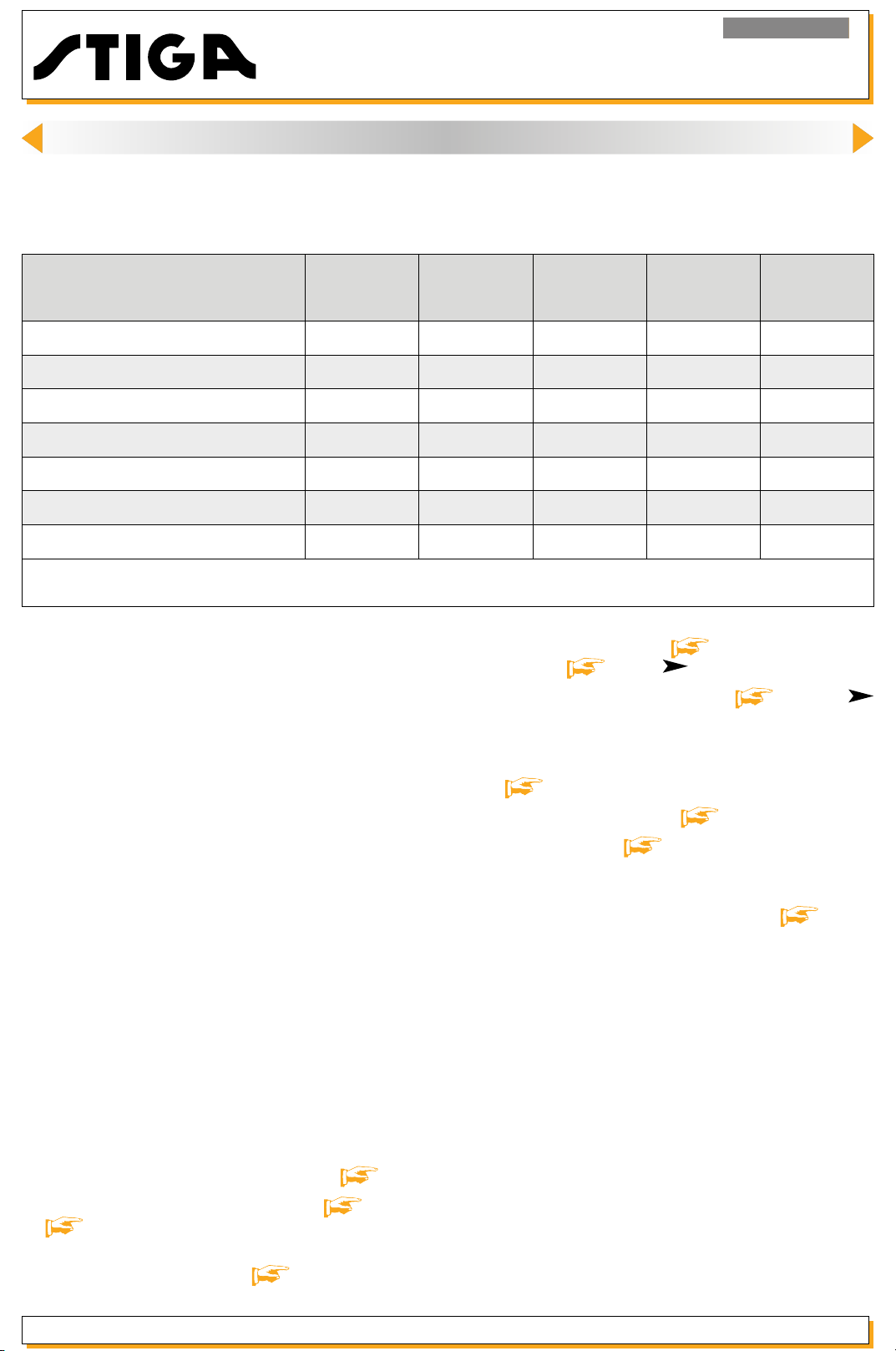
The engine requires a series of interventions (shown in the table below) in order to ensure minimum basic
maintenance.
Operation First 5 hours
Check oil level
Change oil *
Clean mufer and engine
Check air cleaner *
Replace air cleaner *
Check spark plug
Replace spark plug
(1)
*
Replace the oil every 25 hours if the engine is working at full load or at high temperatures.
(2)
*
Clean the air lter more often if the machine is working in dusty areas.
(1)
(2)
(2)
- ■ - - -
■ - - ■ -
- ■ - - -
- ■ - - -
- - ■ - -
- ■ - - -
- - - ■ -
For the operations that are not difcult for the nal
user the assistance centre must maintain the mo-
tor in perfect efciency, in accordance with two
intervention lines:
- Tuning the engine whenever possible.
- Recommending the client a routine maintenance program at set intervals (e.g. at the end of the
season or before a long period of inactivity).
Every 5 hours
or daily
- adjusting minimum [ 8.3] and maximum
speeds
-
adjusting maximum speeds
RS100)
-
inspecting the condition of the spark plug;
checking the distance between the electrodes
[ 11.1];
- tightening the screws [ 15.2];
Every 25
hours or
every season
[ 10.2] ( RSC100)
;
Every 50
hours or
every season
[ 10.2a] (
Every 100
hours
4.2. Engine tuning program
As part of general engine tuning or any intervention
on the lawn tractor, it is recommended that the Service Centre performs a series of operations aimed
at maintaining the engine’s efciency.
Tuning should involve:
- external blowing and cleaning the cylinder
head, cylinder and mufer by removing any
remains of grass and mud;
- checking the oil level, topping up or replacing
parts if necessary
inspecting the condition of the starter rope and
checking that it functions correctly
;
[
6.2];
- cleaning and oiling the air lter [ 7.1] e [
7.1a];
- emptying and cleaning the fuel tank and checking the breather pipe [ 5.2];
Release 00 - 03/2018
page 13
functional test [ 4.3].
-
Should the checks and adjustments fail to achieve
a satisfactory result, refer to chapter
[ 16] for
troubleshooting.
Service manual
Page 14

4. ENGINE TUNING AND TESTING
<< BACK >>
4.3. Functional test
A functional test needs to be carried out at the
end of each servicing operation, to check that the
operations made are effective. The test must be
performed in compliance with the safety regulations regarding the use of the lawnmower on which
the engine is installed.
The functional test is carried out as follows:
a. Refuelling and checking the supply system
When you have refuelled the tank with new petrol,
check the seal of the tank, the cap and the carburettor pipe.
Engine RS100 - RSC100
b. Cold starting test (
With the throttle control in “CHOKE”, start the engine
a few times to check it runs normally.
c. Check the engine rpm
When the engine is hot enough, check the engine
speed with the throttle control set to “SLOW” and
” ( RSC100)
“FAST
to the specications
d. Hot start test
With the engine hot and the throttle control set to
“SLOW” ( RSC100), start the engine a few times
to check it runs normally.
If all of these operations have a positive result, the
engine can be considered fully serviceable and be
returned to the client.
RSC100)
; the readings should be equal
[ 3.2].
Service manual
page 14
Release 00 - 03/2018
Page 15

Engine RS100 - RSC100
<< BACK >>
5. TANK AND SUPPLY
IMPORTANT: Carefully read the information below before commencing any intervention.
General Information
The fuel supply system comprise
the bottom of the tank prevents deposits and impurities from reaching the carburettor.
The tank is equipped with a lter, located at the bottom of the tank, which prevents deposits and impurities
from reaching the carburettor.
The supply to the carburettor o
tank as the engine runs is compensated by a breather pipe in the cap.
s the petrol tank connected to the carburettor by a pipe; a mesh lter at
at chamber is caused by gravity and the volume of petrol taken from the
See the relevant section
supply system.
WARNING: All interventions on the supply system must be performed in safe conditions, therefore:
- do not smoke;
- always empty the tank;
- work in a ventilated env
- collect any remaining petrol by positioning a suitable container under the engine, avoiding soiling the
work bench;
- remove all traces of spilt petrol immediately;
- check you have connected the pipes before pouring petrol back into the tank.
[
16] for advice on resolving problems due to the malfunctioning of the petrol
ironmentawayfromnakedamesorunprotectedsourcesofheat;
Release 00 - 03/2018
page 15
Service manual
Page 16

Engine RS100 - RSC100
<< BACK >>
5. TANK AND SUPPLY
5.1. Emptying and removing the tank
1 - Remove the ring (1) of the petrol pipe (2) from
the tank side and drain all the fuel from the tank
and the pipe into a suitable container.
2
1
4
3
4
6
5
2 - Remove the starter assembly (3) by loosening
the three nuts (4).
3 - Loosen the rear screw (5) and remove the tank
(6).
4 - When tting, perform the ab
reverse.
WARNING:Beforerellingthetankwithnew
fuel, check that the petrol pipe is intact.
ove operations in
7
Service manual
5.2. Cleaning the tank
1 - Remove the tank
2 - Remove the clamp (1) from the side of the tank
and disconnect the petrol pipe (2).
3 - Slide out the lter tube (7) and blow compressed
air through it so as to remove any deposits inside.
4 - Keeping the hole (8) in the spigot closed, pour
about 100 cc of clean petrol into the tank and
shake it vigorously to clean the inside.
8
page 16
[
5.1].
Release 00 - 03/2018
Page 17

Engine RS100 - RSC100
<< BACK >>
5. TANK AND SUPPLY
5 - Empty the tank and dispose of the petrol used
for cleaning in accordance with the laws in force.
9
6 - Ret the tank
(5) to the torques indicated.
7 - Replace the starter assembly by securing the
nuts (4) at the specied torque.
WARNING: Beforerellingthetankwithnew
fuel, check that the petrol pipe is intact.
9
[ 5.1] tightening the screws
10
11
5.3. Checking and cleaning the breather pipe
1 - Remove the cap (9) and pull out the gasket (10)
and the sponge (11).
2 - Check that:
12
- the gasket (10) is intact and without cracks or
ssures;
- the air passages (12) inside the cap are not clogged;
- the sponge (11) is not crushed or broken.
NOTE: Always replace the entire cap if the
gasket or sponge is damaged.
Release 00 - 03/2018
page 17
Tightening torques
4
Assembly xing nut 8-10 Nm
5 Tank xing screw 8-10 Nm
Service manual
Page 18

Engine RS100 - RSC100
<< BACK >>
6. STARTING SYSTEM
General information
The starte
pulley to the fan (and therefore to the engine shaft) is transmitted through a pair of couplings. The return of
the pulley and the rewinding of the rope are obtained from a spiral spring.
r assembly inside the cover consists of a rope wound around a pulley. The movement from the
See the releva
ting system.
3
nt section [
2
16] for advice on resolving problems due to the malfunctioning of the star-
6.1. Removing the starter assembly
3
1
3
1 - To get access to the starter assembly (1), the
cover (2) must be removed by unscrewing the
three nuts (3).
2 - Ret the starter assembly (1) by tightening the
cover nuts (3) to the torque indicated.
6.2. Replacing the rope
1 - Remove the starter assembly
2 - Keep hold of the pulley (4) and slowly unwind
(clockwise) the entire rope (5) to gradually release
the return spring.
If the rope breaks, the spring will be already released and you will only have to unwind the rope.
4
5
5
4
3 - Undo or cut the knot at the end of the rope
(5) and remove the section still attached to the
pulley.
[
6.1].
Service manual
page 18
Release 00 - 03/2018
Page 19
Engine RS100 - RSC100
<< BACK >>
6. STARTING SYSTEM
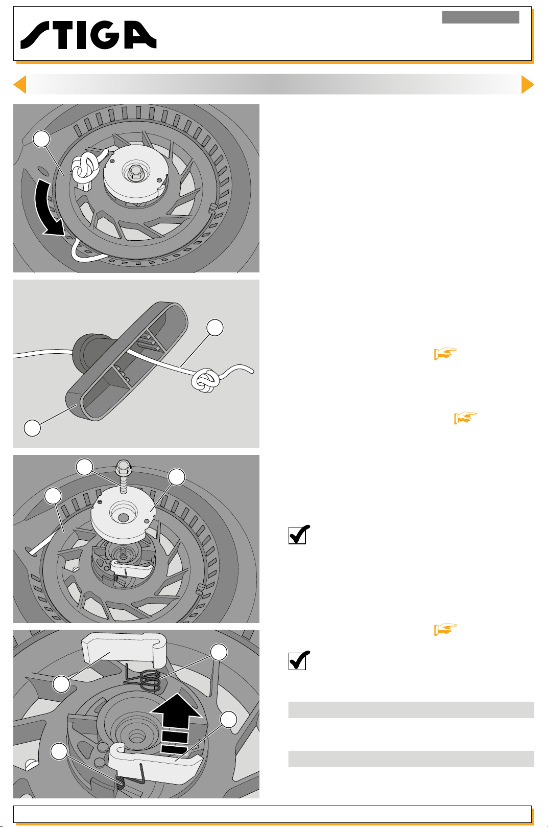
4 - Rotate the pulley (4) through about 6 complete
turns anticlockwise in order to load the spring and
4
5
hold it still.
5 - Insert one end of the rope (5) (ø 3mm - length
2350mm) through the gui
into the hole in the pulley (4), and fasten it by tying
a knot.
6 - Insert the other end of the rope into the grip
(6), fasten it with a knot and carefully release the
pulley to allow the rope to rewind itself completely
onto the pulley.
7 - Check that the pulley rotates freely.
8 - After pulling the entire length of the rope, check
that the pulley (4) is able to complete another 2-3
turns before compressing the spring.
de in the ventilation grille,
9 - Ret the starter assembly
6.3. Replacing the hooks
6
7
8
4
1 - Remove the starter assembly
2 - Loosen the screw (7) and remove the cover (8),
putting the spring to one side. Be careful not to slip
the pulley (4) off its seat.
3 - Remove the couplings (9) and take out the
springs (10) from their seats.
NOTE: Always replace the complete set
consisting of hooks, return springs, cover and
screw, as a unit.
4 - When tting, tighten the screw (7) to the torque
indicated.
5 - Ret the starter assembly
[ 6.1].
[
[
6.1].
6.1].
9
10
Release 00 - 03/2018
10
9
page 19
NOTE: Check that the spring lever (10) is
outside the coupling (9).
Tightening torques
3
Fixing nuts, starter assembly
7 Starter screw 4-6 Nm
Technical information
Starter rope dimensions ø 3x2350 mm
Service manual
8-10 Nm
Page 20

Engine RS100 - RSC100
<< BACK >>
7. INTAKE SYSTEM
General information
The intake system uses an air lter directly connected to the carburettor by means of a manifold which
conveys the air/petrol mixture to the inlet valve.
See the relevant section
intake system.
Aninefcientltercanletdustordebrisenterthecylinder,causingprematureweartothepistonringsand
cylinder.
The air lter is found on the left hand side of the engine and can be inspected without having to remove
other parts.
The lter assembly is to be removed only to accede the carburettor.
[
16] for advice on resolving problems due to the malfunctioning of the air
7.1. Maintenanceand replacement of the lter
element
2
1
2
1
WARNING: Never run the engine without air
lter.Theenginewouldcertainlybedamaged.
1 - Clean the area around the lter cover (1) by
blowing it with compressed air.
2 - Remove the cover (1) by pressing on the upper
tab (2).
WARNING: Close the intake duct to prevent
theentryofforeignobjects(seegure).
3 - Remove the lter eleme
4 - Check carefully that the element has no holes
3
3
or tears, and replace it, if damaged.
nt (3).
Service manual
page 20
Release 00 - 03/2018
Page 21
7. INTAKE SYSTEM
<< BACK >>
Engine RS100 - RSC100
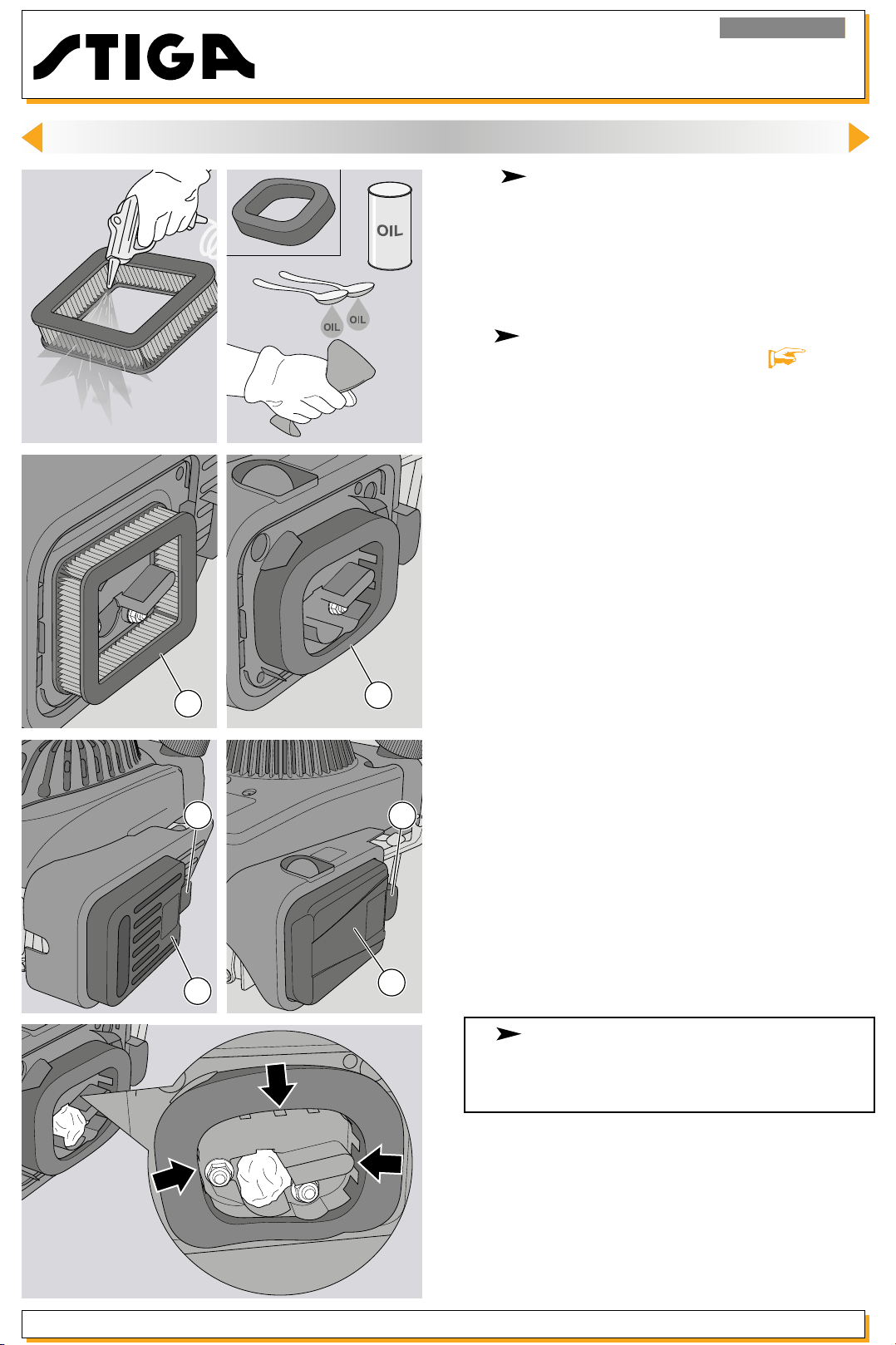
5 -
element on a hard surface so as to remove excess
dirt, and blow it through with compressed air, outwards from the inside.
Replace the element if it is too dirty.
6 nance referred to in the paragraph
Cartridgelterelement: Bang the air lter
Spongelterelement: Perform the mainte-
[ 7.1a].
7 - Ret the element (3) and the cover (1) into their
3
2
1
3
2
1
housings, into its housing, paying attentio
up the clips correctly (2).
8 -
sponge lter element, make sure it is properly positioned between the tabs, as shown in the gure.
model RS100 During the installation of the
n to hook
Release 00 - 03/2018
page 21
Service manual
Page 22

7. INTAKE SYSTEM
<< BACK >>
7.1a. Maintenanceofspongelteringelement (
model RS100)
Engine RS100 - RSC100
1 - Remove the cover [
lter element (1).
WARNING: Close the intake duct to prevent
the entry of foreign objects.
1
2 - Check carefully that the element has no holes
or tears, and replace it, if d
WARNING:Thelterelementmustbekept
clean and oil soaked and must be replaced if broken, cut or if it is crumbling.
Donot usecompressedairtocleanthelterelement.
3 - Wash the lter element with water and detergent
and dry with a clean cloth.
7.1] and remove the
amaged.
4 - Pour two spoons of clean motor oil onto the
element and wring the sponge repeatedly until the
oil is evenly spread.
5 - Remove any excess oil with a clean cloth.
6 - Replace the lter element as shown in points 6
and 7 of the paragraph
[ 7.1].
Service manual
page 22
Release 00 - 03/2018
Page 23

8. CARBURATION ( valid for RSC100 model)
<< BACK >>
General information
The carburettor has a oat with a xed jet and a “CHOKE” control.
Engine RS100 - RSC100
See the relevant section
The carburettor is located on the left-hand side of the engine. For maintenance operations it is necessary
to dismantle the air intake lter in the sequence shown below.
Dismantle the engine from the machine following the instructions in section
[
16] for advice on resolving problems due to carburation.
WARNING! All operations on the tank and
supply system must be carried out in safe
conditions, so:
1
3
2
- do not smoke;
- always empty the tank if petrol is not strictly
necessary for the operation to be carried out;
- work in a ventilated environment away from
nakedamesorunprotectedsourcesofheat;
- collect petrol in a suitable container with a cap
using a funnel and avoid spilling it on the work
bench;
[ 15.1].
- remove all traces of spilt petrol immediately;
- check you have connected the pipes before
pouring petrol back into the tank.
5
8.1. Removing and cleaning the carburettor
1 - Remove the lter element
2 - Unscrew the two nuts (1) holding the lter carrier
4
(2) to the engine and remove it. Pull off the breather
tube (3).
3 - Remove the clamp (4) for the petrol pipe (5)
from the side of the carburettor and use a suitable
container to collect all the petrol in the pipe.
4 - Remove the gasket (6) and bring the intake throttle rod to a minimum, pulling out the carburettor.
[
7.1].
Release 00 - 03/2018
6
page 23
Service manual
Page 24

Engine RS100 - RSC100
<< BACK >>
8. CARBURATION ( valid for RSC100 model)
7
9
8
10
5 - Using pliers, disconnect the intake buttery rod
(7) and slide the small rod (8) for the relative compensation spring upwards.
6 - Disconnect the wire (9) from the choke buttery
lever, completely remove the carburettor (10) for
the relative compensatio
n spring upwards (11).
15
11
12
13
NOTE: Empty any remaining petrol from the
tank by removing the drain screw (12) as
showninthegure.Whennished,replace
the screw.
7 - Unscrew the central screw (13) securing the tank
(14) and remove the corresponding OR (15).
14
Service manual
page 24
Release 00 - 03/2018
Page 25
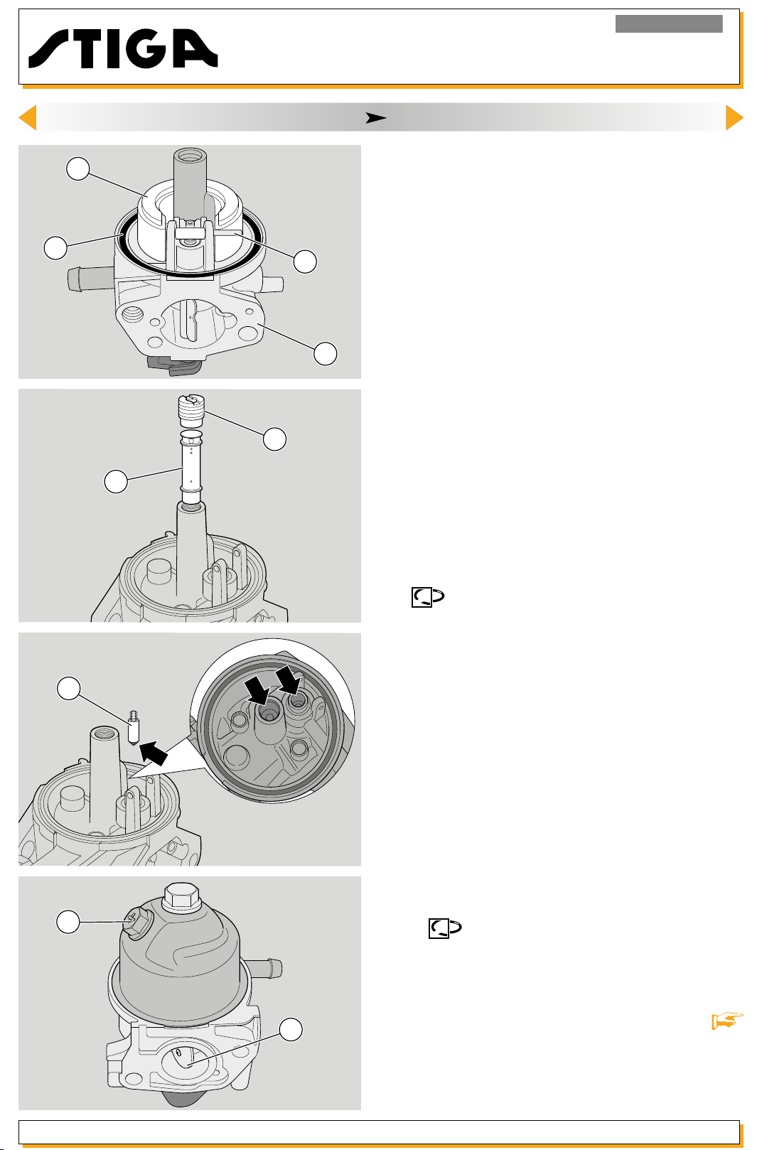
18
<< BACK >>
17
20
Engine RS100 - RSC100
8. CARBURATION ( valid for RSC100 model)
8 - Pull out the pin (16), dismount the oat (17) and
remove the gasket (18).
9 - Undo the main jet (19) and pull out the pilot jet
(20).
16
10 - Check that no impurities or dirt are deposited
in the seat of the needle (21) and of the pilot jet.
Make sure the rubber tip of the needle and the
oatarenotmarkedorworn.Iftheyare,replace
10
19
them.
11 - Clean the carburettor (10) the main jet (19) and
the pilot jet (20) thoroughly by immersing them in
clean petrol (or a detergent) for 24 hours.
Dry with compressed air, blowing well through the
carburettor holes.
21
12
12 - Mount the carburettor following the previous
points 8, 7 and 6 in reverse order, remembering
that:
It is always advisable to replace the washer
-
(18) and the O-Ring (15) of the oat chamber;
- the oat (17) must oscillate freely on the pin (16);
- the jet (19) should never be modied or replaced
with others even if they seem to have the same
specications;
- the choke (22) must open and close regularly;
- the screw (12) to drain the tank should be facing
the front of the engine.
13 - Remount the tie rods (7), (8) and (9) checking
that the governor system moves smoothly without
stopping.
14 re-mounting the carburettor onto the engine.
Always replace washers (6) and (11) when
Release 00 - 03/2018
22
page 25
15 - Fit the lter and tighten the relative nuts (1) to
the torque indicated. Ret the lter element
7.1].
Service manual
[
Page 26

Engine RS100 - RSC100
<< BACK >>
8. CARBURATION ( valid for RSC100 model)
8.2. Replacing the carburettor
1 - Perform operations 1 - 2 - 3 - 4 - 5 - 6 - 12 - 13 - 14
- 15 indicated in section
[
8.1] above.
SLOW
8.3. Adjusting minimum speed
1 - Check that the throttle cable is adjusted cor-
[
rectly
10.1].
2 - Let the engine heat up for a few minutes, then
set the throttle control to “SLOW”.
Check the rotation speed on the speed indi-
cator (23).
NOTE: The engine’s minimum speed must be
between 1800 (±100) rpm.
3 - Turn the screw (24) until you achieve a stable
minimum speed within the above values.
8.4. Adjusting maximum speed
Service manual
24
23
page 26
NOTE: This operation is carried out by adju-
sting the governor system
[ 10.2].
8.5. Adjusting the carburation
NOTE: The carburation is set in the factory
and does not normally need changing. In the
event of irregular functioning, clean the carburettor as indicated in section
[ 8.1].
Tightening torques
1 Carburettor nuts/lter 6-8 Nm
Technical information
Minimum speed (SLOW) 1800 (±100) g/1’
Special equipment
23 Speed indicator
Release 00 - 03/2018
Page 27

9. CARBURATION ( valid for RS100 model)
<< BACK >>
General information
The carburettor is a xed jet oating type with “PRIMER”.
Engine RS100 - RSC100
See the rele
The carburettor is located on the left-hand side of the engine. For maintenance operations it is necessary
to dismantle the air intake lter in the sequence shown below.
Dismantle the engine from the machine following the instructions in section
vant section [
2
16] for advice on resolving problems due to carburation.
[ 15.1].
WARNING! All operations on the tank and
supply system must be carried out in safe
conditions, so:
- do not smoke;
- always empty the tank if petrol is not strictly
necessary for the operation to be carried out;
- work in a ventilated environment away from
nakedamesorunprotectedsourcesofheat;
2
1
- collect petrol in a suitable container with a cap
using a funnel and avoid spilling it on the work
bench;
- remove all traces of spilt petrol immediately;
- check you have connected the pipes before
pouring petrol back into the tank.
9.1. Removing and cleaning the carburettor
1 - Remove the lter element
2 - Remove the two nuts (1) securing the lter hol-
4
3
5
der (2).
3 - Remove the lter holder (2), disconnecting the
vent pipe and paying attention to the “PRIMER”
pipe.
4 - Remove the clamp (3) and the “PRIMER” pipe
(4). Use a suitable container to collect all the petrol
in the pipe.
5 - Remove the gasket (5) and bring the intake throttle rod to a minimum, pulling out the carburettor.
[
7.1].
Release 00 - 03/2018
page 27
Service manual
Page 28

Engine RS100 - RSC100
<< BACK >>
9. CARBURATION ( valid for RS100 model)
6 - Using pliers, disconnect the intake buttery rod
6
7
(6) and slide the small rod (7) for the relative compensation spring up
7 - Completely remove the carburettor (8) and the
gasket (9).
wards.
8
9
NOTE: Empty any remaining petrol from the
tank by removing the drain screw (10) as
showninthegure.Whennished,replace
the screw.
10
13
Service manual
11
12
page 28
8 - Unscrew the central screw (11) securing the tank
(12) and remove the corresponding OR (13).
Release 00 - 03/2018
Page 29
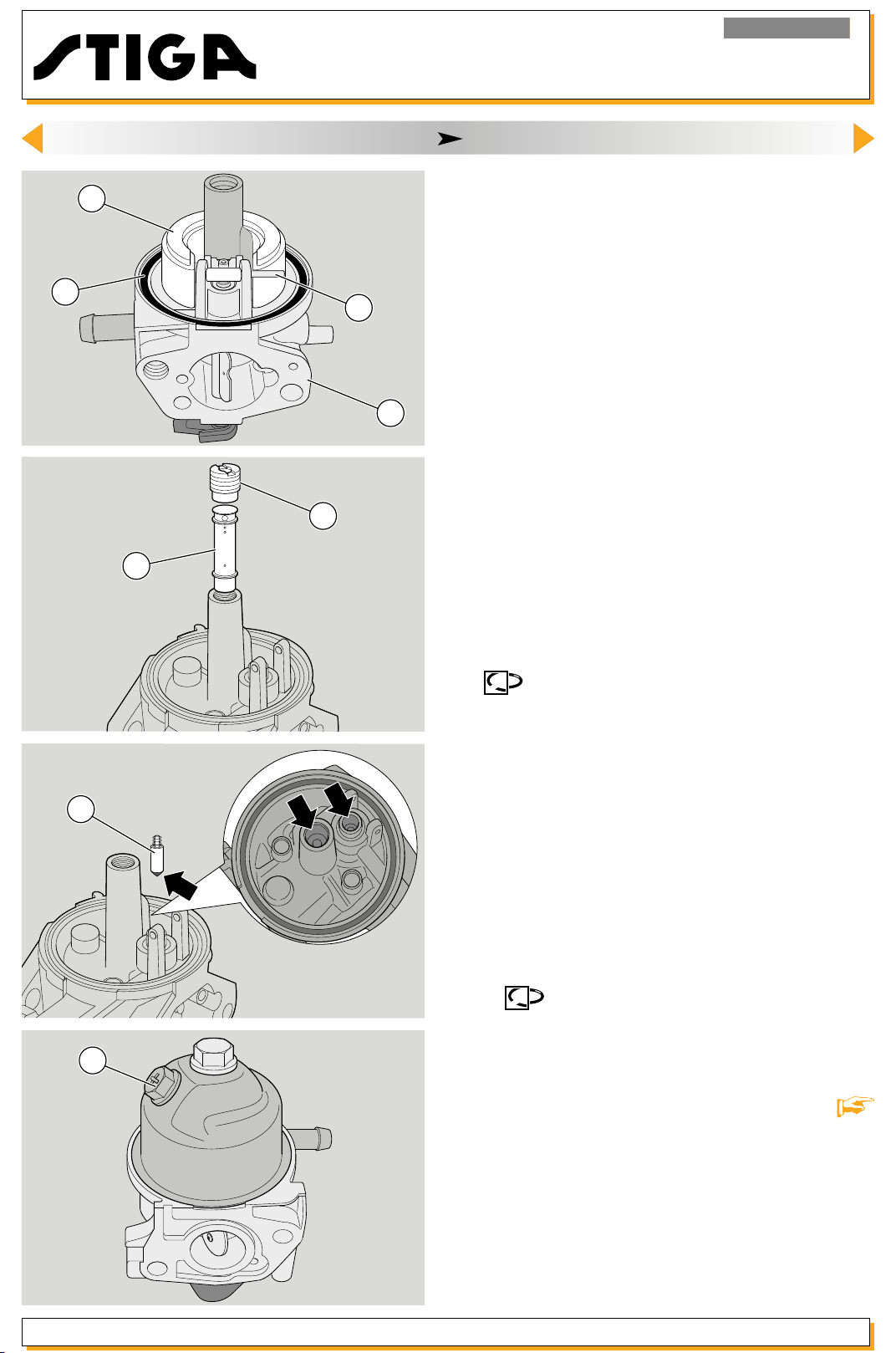
15
<< BACK >>
Engine RS100 - RSC100
9. CARBURATION ( valid for RS100 model)
9 - Pull out the pin (14), dismount the oat (15) and
remove the gasket (16).
10 - Undo the main jet (17) and pull out the pilot
jet (18).
16
18
17
14
11 - Check that no impurities or dirt are deposited
in the seat of the needle (17) and of the pilot jet.
Make sure the rubber tip of the needle and the
oatarenotmarkedorworn.Iftheyare,replace
8
them.
12 - Clean the carburettor (8) the main jet (17) and
the pilot jet (18) thoroughly by immersing them in
clean petrol (or a detergent) for 24 hours.
Dry with compressed air, blowing well through the
carburettor holes.
13 - Mount the carburettor following the previous
points 9, 8 and 7 in reverse order, remembering
that:
-
It is always advisable to replace the washer
(16) and the O-Ring (13) of the oat chamber;
- the oat (15) must oscillate freely on the pin (14);
19
10
- the jet (17) should never be modied or replaced
with others even if th
specications;
- the screw (10) to drain the tank should be facing
the front of the engine.
14 - Remount the tie ro
that the governor system moves smoothly without
stopping.
15 re-mounting the carburettor onto the engine.
16 - Fit the lter and tighten the relative nuts (1) to
the torque indicated. Ret the lter element
7.1]
Always replace washers (5) and (9) when
.
ey seem to have the same
ds (6) and (7) checking
[
Release 00 - 03/2018
page 29
Service manual
Page 30

Engine RS100 - RSC100
<< BACK >>
9. CARBURATION ( valid for RS100 model)
9.2. Replacing the carburettor
1 - Perform operations 1 - 2 - 3 - 4 - 5 - 6 - 7 - 13 - 14
- 15 - 16 indicated in section
9.3. Adjusting maximum speed
NOTE: This operation is carried out by adju-
sting the governor system
9.4. Adjusting the carburation
[
9.1] above.
[ 10.2a].
NOTE: The carburation is set in the factory
and does not normally need changing. In the
event of irregular functioning, clean the carburettor as indicated in section
Tightening torques
1 Carburettor nuts/lter 6-8 Nm
[ 9.1].
Service manual
page 30
Release 00 - 03/2018
Page 31

Engine RS100 - RSC100
<< BACK >>
10. GOVERNOR SYSTEM OF THE CARBURETTOR
General information
The carburettor governor system uses a engine shaft linkage tted on a support xed to the left-hand side of
the engine, completed by a counterweight device, driven by the camshaft, and thus sensitive to changes
in the engine’s revolution pattern depending on load.
The force of the counterweights, transferred to the control lever, tends to shut the main carburettor butter-
y, in opposition with the spring that would keep it open; the balance between the spring loading and the
thrust of the counterweights on the control lever modies the buttery opening and adapts the ow of fuel
to the engine so that the revolution speed is kept constant with engine load changes.
See the relevant section
[
16] for advice on resolving problems related to the governor system.
10.1. Adjusting of a
ccelerator cable (
model
RSC100)
1 - Remove the lter holder
[
8.1].
3
2 - Loosen the screw (1) of the clamp (2) so that the
cable casing (3) is free to move.
2
1
3 - Set the throttle control lever (4) to “CHOKE”.
CHOKE
4
5
Release 00 - 03/2018
4 - Move governor control lever (5) forward as far
as possible and, by keeping it in this position, lock
the casing (3) full tightening the screw (1) of the
clamp (2).
2
3
1
page 31
Service manual
Page 32
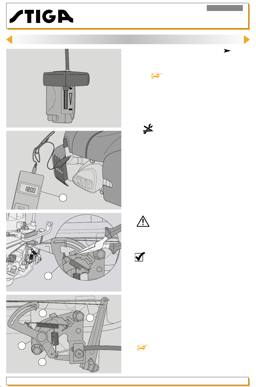
Engine RS100 - RSC100
<< BACK >>
10. GOVERNOR SYSTEM OF THE CARBURETTOR
10.2. Adjusting maximum speed ( model
RSC100)
1 - Check that the throttle cable is adjusted correctly
[
10.1].
FAST
2 - Let the engine heat up for a few minutes then
set the throttle control to “FAST”.
3 -
Check the rotation speed on the speed
indicator (6).
4 - Bend the plate (7) slightly upwards using pliers
to increase the engine RPM and downwards to
decrease it.
5 - Check by moving the lever to the “SLOW” position and then to the “FAST” position to eliminate
6
any slack. Check the RPM again using the engine
speed indicator.
Make sure the accelerator is in the “FAST”
position and check the air lever rod is not already
activated or in contact.
11
Service manual
NOTE: The engine’s maximum speed must be
between 2900 (±100) rpm; if you do not read
this value, proceed as follows.
7
6 - Check:
- that the spring (8) is intact and that it is properly
positioned in its seat;
9
10
- that the wire (9) and th
e relative spring (10) are
intact and not deformed;
- that the moving levers (11) are not bent or deformed and replace the entire support if necessary
[ 10.3].
8
page 32
Release 00 - 03/2018
Page 33

11
<< BACK >>
Engine RS100 - RSC100
10. GOVERNOR SYSTEM OF THE CARBURETTOR
7 - If the above checks do not show any faults,
the phasing of the governor’s control lever (12)
with respect to the counterweight device must be
10
8
9
12
14
13
checked:
- stop the engine and move the accelerator control
to “FAST”;
- slacken off the control lever (13) locknut (12);
- without changing the lever (12) position determined by the spring (10) and tie-engine shaft (9), use
a screwdriver to turn pin (14) clockwise to the end
of its stroke and then lock the nut (13).
Release 00 - 03/2018
page 33
Service manual
Page 34

Engine RS100 - RSC100
<< BACK >>
10. GOVERNOR SYSTEM OF THE CARBURETTOR
10.2a. Adjusting maximum speed
RS100)
1 - Check the rotation speed on the speed
tor (5).
indica
5
2 - Bend the plate (6) slightly upwards using pliers
to increase the engine RPM and downwards to
decrease it.
NOTE: The engine’s maximum speed must be
between 2800 (±100) rpm; if you do not read
6
this value, proceed as follows.
( model
9
7
9
8
8
10
3 - Check:
- that the spring (7) is intact and that it is properly
positioned in its seat;
- that the wire (8) and the relative spring (9) are
intact and not deformed;
4 - If the above checks do not show any faults,
the phasing of the governor’s control lever (10)
with respect to the counterweight device must be
checked:
- stop the engine and make sure that the lever (10)
is in the end run position;
- slacken off the control l
- without changing the lever (10) position determined by the spring (9) and tie-engine shaft (8), use
a screwdriver to turn pin (12) clockwise to the end
of its stroke and then lock the nut (11).
ever (11) locknut (10);
Service manual
7
12
11
page 34
Release 00 - 03/2018
Page 35

Engine RS100 - RSC100
<< BACK >>
10. GOVERNOR SYSTEM OF THE CARBURETTOR
16
17
15
15
3
8
10.3. Replacing the lever support ( model
RSC100)
1 - Remove the lter element
lter holder
2 - Position the choke lever to minimum (“SLOW”
position).
3 - Disconnect the accelerator cable (3) and the
spring (8).
4 - Loosen the two screws (15) securing the support
(16) to the engine and the clip (17) securing the
petrol pipe.
5 - Turn the lever support and remove the tie-rod
(18) on the starter throttle lever (CHOKE).
[ 8.1].
[
7.1] and the
18
17
6 - Perform the above operations in reverse order
when assembling.
7 - Replace the lter holder
element
8 - Adjust the maximum speed
Tightening torques
15
Technical information
Maximum speed (FAST)
Special equipment
6 Speed indicator
[ 7.1].
Support screw, governor
assembly
[ 8.1] and the lter
[ 10.2].
8-12 Nm
2900 (±100) g/1’
Release 00 - 03/2018
page 35
Service manual
Page 36
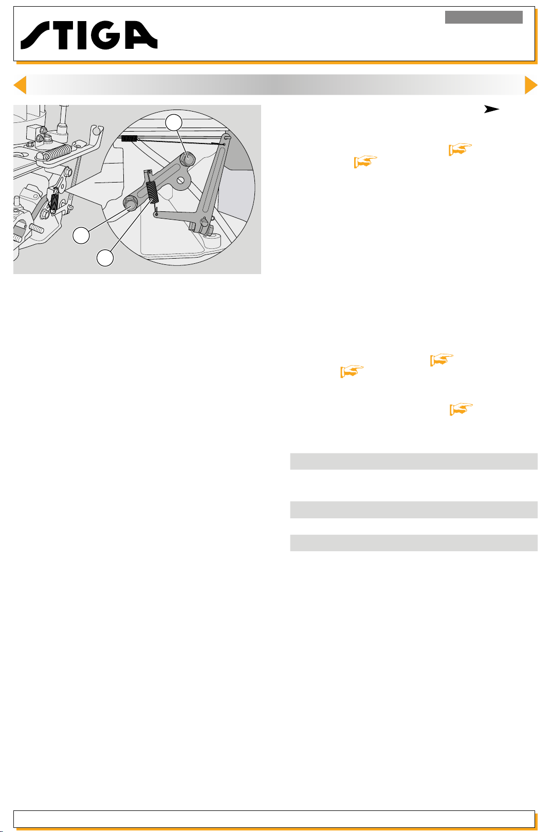
13
<< BACK >>
Engine RS100 - RSC100
10. GOVERNOR SYSTEM OF THE CARBURETTOR
10.3a. Replacing the lever support ( model
13
RS100)
1 -
Remove the lter element [
lter holder
2 - Disconnect the spring (7).
[ 9.1].
7.1] and the
7
3 - Remove the two screws (13) and replace the
lever support.
4 - Perform the ab
when assembling.
7 -
Replace the lter holder [ 9.1] and the lter
element
8 - Adjust the maximum speed
Tightening torques
13
Technical information
Maximum speed
Special equipment
5 Speed indicator
[ 7.1].
Support screw, governor
assembly
ove operations in reverse order
[ 10.2a].
8-12 Nm
2800 (±100) g/1’
Service manual
page 36
Release 00 - 03/2018
Page 37

Engine RS100 - RSC100
<< BACK >>
11. IGNITION
General information
The ignition system has a fan with an electronic coil which supplies high voltage to the spark plug
.
See the relevant section [
The coil and complete fan are accessible by removing the cowl.
Dismount the engine from the machine by following the instructions in section
2
16] for advice on resolving problems related to the ignition.
0,6 - 0,8 mm
1
11.1. Checking the efficiency of the ignition
system
1 - Dismount the spark plug (1) and look at the colour on the end of the thread. This can give you a
good idea of the carburation:
- black: mixture too greasy due to clogged air
lter;
- nut brown: regular carburation.
Replace the spark plug (with one of the same or
equivalent characteristics) if the electrodes (2) are
burnt or if the porcelain is broken or cracked.
[ 15.1].
4
3
5
FIRE HAZARD:
- do not check the ignition system if the spark
plug is not screwed in place;
-
spark test.
2 cap (4) and to earth on the engine (5). Activate
the starter and see in the instrument if the spark
jumps.
3 - If the test has a positive result, clean the electrodes (2) with compressed air and adjust the distance
to 0.6-0.8 mm. Remount the spark plug and tighten
it to the specied levels.
Unless otherwise required, proceed to verify system
components as indicated in section
always use the specic toolfor the
Connect the tester (3) to the spark plug
11.2].
[
Release 00 - 03/2018
page 37
Service manual
Page 38

11. IGNITION
<< BACK >>
Engine RS100 - RSC100
10
8
6
11
9
7
11.2. Adjusting the air gap and checking the coil
1 - Remove the starter assembly
2 - Make sure that the earth cable faston (6) of the
coil (7) is not oxidized; if it is, disconnect, clean and
remount it, spraying it with a special antioxidant.
3 - Check that the coil earth cable is intact. The
black spark plug cable (8) should not have any
cracks or signs of deterioration or burns which re-
duce its efciency and insulation level.
4 - Slack off the screw (9) and the stud (10) which
secure the coil (7).
At the bottom of the machine to which the engine
is tted, release the safety brake.
Rotate the fan (11) so as to bring the magnetic
inserts next to the poles of the core of the coil.
[
6.1].
10
5 - Insert a 0.35 mm thickness gauge (12) between
the complete fan (11) and the coil poles (7), push
the coil until the poles come in contact with the
thickness gauge and secure screw (9) and stud
12
7
11
0,35÷0,45 mm
9
6
(10); with the ywheel locked, the airgap must be
between 0.35 and 0.45 mm.
NOTE: An accurate inspection of the ef-
ciency of a coil can only be carried out in a
laboratory equipped with a oscilloscope.
To make a brief check, proceed as follows:
6 - Disconnect the earth cable faston (6) of the
coi (7).
Service manual
page 38
Release 00 - 03/2018
Page 39

13
<< BACK >>
11. IGNITION
7 - Perform a spark test as indicated in [ 11.1].
- If the spark jumps: the coil functions properly and
in the event of malfunction, verify that the cut-off
cable (13) is not earthed.
- if the spark does not jump: the coil is faulty and
must be replaced
Engine RS100 - RSC100
[ 11.3].
10
8 - Ret the starter assembly
11.3. Replacing the coil
1 - Remove the starter assembly [
7
11
9
6
2 - Disconnect the faston of the earth cable (6).
3 - Undo the screw (9) and the stud (10) and remove
the coil (7).
4 - Mount the new coil and regulate the air gap
according to the procedure indicated in points 4
and 5 in section
5 - Connect the faston of the earth cable (6).
[ 11.2].
[ 6.1].
6.1].
Release 00 - 03/2018
page 39
6 - Ret the starter assembly
Tightening torques
1 Spark plug tightening torque 16-20 Nm
Coil xing screw 8-12 Nm
9
Coil xing stud 8-12 Nm
10
Technical information
Type of spark plug GGP K7 RTC
Distance between electrodes 0,6-0,8 mm
Air gap/fan 0,35-0,45 mm
Special equipment
3 Tester for spark test
[ 6.1].
Service manual
Page 40

Engine RS100 - RSC100
<< BACK >>
12. TURNING OFF AND STOPPING THE ENGINE
General information
The engine is turned off and stopped by releasing a lever on the lawnmower. The cable acts on a lever
which simultaneously activates a microswitch that sends the coil to earth as well as a brake which acts on
the ywheel.
The brake must be able to stop the engine within 3 seconds after it is turned off.
To solve problems in the system for turning off and stopping the engine, see the relevant chapter
To get access to the system for turning off and stopping the engine, remove the starter assembly.
12.1. Checking the control cable
1 - Remove the starter assembly
1
3
5
2
4
7
2 - Remove the lter assembly
RSC100 (or
3 - Check that the sheath (1) is not bent, that the
wire (2) is securely connected to both the lawnmower lever and the lever (3) on the engine and
that the terminal (4) is correctly fastened to the
support (5).
4 - Check that the wire (2) runs freely inside the
sheath (1) when you move the lever.
5 - Check that the end of the wire (2) is slightly loose
when you release the lawnmower lever.
[ 9.1] mod. RS100).
[
[ 8.1] mod.
[
6.1].
16].
Service manual
6 - Ret the lter assembly [ 8.1] mod.
RSC100 (or
7 - Ret the starter assembly
6
12.2.
1 - Disconnect the coil Faston connector (6).
2 make contact with the leads on the points indica-
ted in the gure.
The instrument should read:
- ∞ = microswitch press
- 0 = microswitch free (lever released);
Otherwise, replace the system for turning off and
stopping the engine.
page 40
[ 9.1] mod. RS100).
[ 6.1].
Checking the system for turning off the engine
Using a multimeter (7) as an ohmmeter,
ed (lever pulled);
Release 00 - 03/2018
Page 41

Engine RS100 - RSC100
<< BACK >>
12. TURNING OFF AND STOPPING THE ENGINE
12.3. Checking the brake
8
1 - Remove the starter assembly
[
6.1].
5
3
2
2 - Check that the thickness of the friction pad (8)
is not less than 2 mm at its thinnest point.
3 - Make sure that the control lever (5) moves freely
and remove any remains of grass and mud.
4 - Ret the starter assembly
5 - Start the engine, release the lawnmower lever
and check that the engine stops within 3 seconds.
6 - If it stops after 3 seconds, replace the entire
assembly
friction pad are not capable of ensuring compliance with braking times.
[ 12.4], because the spring or the
WARNING! Never return the lawnmower to
yourclientwithoutcheckingbrakeefcien-
cy.
[ 6.1].
Release 00 - 03/2018
page 41
Service manual
Page 42

Engine RS100 - RSC100
<< BACK >>
12. TURNING OFF AND STOPPING THE ENGINE
12.4. Replacing the system for turning off and stop-
ping the engine
6
1 - Remove the starter assembly
[ 6.1].
10
10
2 - Remove the lter assembly
RSC100 (or
9
5
11
3 - Disconnect the brake
(3).
4 - Disconnect the earth cable Faston connector
(9).
5 - Loosen the two screws (10) and the spring (11).
Remove the support bracket (5).
6 - When tting, perform the above operations in
reverse, tightening the s
indicated.
7 - Ret the starter assembly
assembly
mod. RS100).
[ 9.1] mod. RS100).
[ 8.1] mod. RSC100 (or [ 9.1]
[ 8.1] mod.
wire (2) from the lever
crews (10) to the torque
[ 6.1] and the lter
8 - Start the engine, release the lawnmower lever
and check that the engine stops within 3 seconds.
Tightening torques
10 Brake support screws
Special equipment
7 Universal tester
8-12 Nm
Service manual
page 42
Release 00 - 03/2018
Page 43

Engine RS100 - RSC100
<< BACK >>
13. EXHAUST SYSTEM
General information
The exhaust system consists of a mufer installed on the cylinder together with a gasket, a spacer and a
heatproof bafe.
To solve problems in the exhaust system, see the relevant chapter
2
3
1
13.1. Removingandreplacingthemufer
1 - Remove the two nuts (1) and the screw (2) that
x the guard (3) and the mufer.
2 - Take out the mufer (4) and the heatproof bafe
(5).
[
16].
3 - On assembly:
- thoroughly clean the cylinder contact surface,
removing all deposits or fragments on the hea-
tproof bafe;
- always replace damaged mufers;
- always replace the heatproof bafe (5) if it is
4
5
broken or cracked;
- tighten the two nuts (1) and the screw (2) to the
specied levels.
Tightening torques
1 Mufer xing nuts
2 Mufer xing screw 8-10 Nm
8-10 Nm
Release 00 - 03/2018
page 43
Service manual
Page 44

Engine RS100 - RSC100
<< BACK >>
14. ENGINE BLOCK - External operations
14.1. Checking the heating unit seal
1 - Remove the cap (1) and take o
plug (2).
2 - Manually set the piston to the TDC (Top Dead
Centre) of the compression stroke so that both
valves are closed.
1
2
3 sting tool (3) into the spark plug hole and connect
the supply pipe to a compressed air socket with a
pressure of approximately 4 bar (58 psi).
4 - On opening the air tap (4), the manometer
gauge on the engine side should position itself in
the green zone and remain there for about 30 seconds. If the gauge falls rapidly it means that the
compression is poor.
Screw the terminal of the compression te-
ut the spark
4
3
NOTE: Lack of compression could be due
to:
- incorrect valve clearance [ 14.2];
-
lack of seal in the valves [
-
piston rings worn [
5 - Ret the spark plug (2) and close it to the indi-
cated couple.
15.4].
15.5];
Service manual
page 44
Release 00 - 03/2018
Page 45

Engine RS100 - RSC100
<< BACK >>
14. ENGINE BLOCK - External operations
14.2. Adjusting the valve clearance
5
6
7
5
WARNING: The adjustment must be made
with the engine is cold.
1 - Remove the cover and demount the spark plug
[
14.1].
2 - Remove lid (5) which is secured with three screws
(6) and remove the washer (7).
3 - Manually set the piston to the TDC (Top Dead
Centre) of the compression stroke so that both
valves are closed.
4 - Use a feeler gauge (8) to check the gap between the rocker arm and the tip of the valve stem; the
gauge should pass between without forcing and
without a further g
5 - Slack is adjusted by loosening the dowel (9) and
suitably adjusting the register nut (10) to obtain the
following values:
ap.
Inlet - IN = 0,15 - 0,20 mm
Exhaust - EX = 0,15 - 0,20 mm
6 - Following adjustment, check that the pushrods
(11) are properly inserted in the rocker arm
(12) and always fully tighten the dowel (9).
7 - When reassembling check the condition
of the gasket (7) of the cover (5) and replace it if
it is damaged. Tighten the screws (6) to the torque
indicated.
8 - Assemble the spark plug [ 14.1].
housings
10
12
11
9
9
10
11
9
8
0,15÷0,20 mm
0,15÷0,20 mm
10
Release 00 - 03/2018
12
9
page 45
Service manual
Page 46

13
<< BACK >>
Engine RS100 - RSC100
14. ENGINE BLOCK - External operations
14.3.
Dismantling and replacing the complete
fan
16
14
15
1 - Remove the starter assembly
2 - Operate the exhaust brake.
3 - Using an airgun, un
4 - Undo the screw (14) and the stud (15) and remove the electronic coil (16).
5 complete fan (17) as in
Ensure that the engine shaft key is retained.
Using a suitable extraction tool, remove the
do the nut (13).
dicated in the diagram.
[
6.1].
18
17
NOTE:Ifitisdifculttodisassemblethefan,
use a hammer and hit the extractor screw.
6 - When tting the complete fan check that the key
(18) is in good condition and replace it, if deformed.
Close the nut (13) to the indicated couple.
7 - Ret the coil (14), tightening the screw (15) and
the stud (16) to the torque indicated.
8 -
Readjust the airgap until it is correct [ 11.2].
9 - Ret the starter assembly [ 6.1].
Service manual
page 46
Release 00 - 03/2018
Page 47

Engine RS100 - RSC100
<< BACK >>
14. ENGINE BLOCK - External operations
14.4. Blow-by check
22
19
21
20
1 - Remove the complete fan
2 - Unscrew the screw (19) xing the closing plate
(20).
3 - Check that the reed (21) is not blocked or deformed. Replace if this is the case.
If necessary wash with water and neutral detergents.
4 ret the closure plate (20), tightening the screw to
the torque indicated.
5 - Ret the complete fan
If necessary, replace the gasket (22) and
[
14.3].
[ 14.3].
23
18
25
24
14.5. Replacing the upper compression ring of the
engine shaft (fan side)
1 - Remove the complete fan
2 - Take out the spline key (18).
3 - Use a thin screwdriver inserted under the sealing
lip to extract the oil seal ring (23).
4 - The new ring (24) must be inserted with the help
of a pipe (25) with a diameter of approximately
35-40 mm, taking care not to damage the sealing
lip.
5 - Ret the key (18) and the complete fan
.
14.3]
[
14.3].
[
Release 00 - 03/2018
page 47
Service manual
Page 48
Engine RS100 - RSC100
<< BACK >>
14. ENGINE BLOCK - External operations
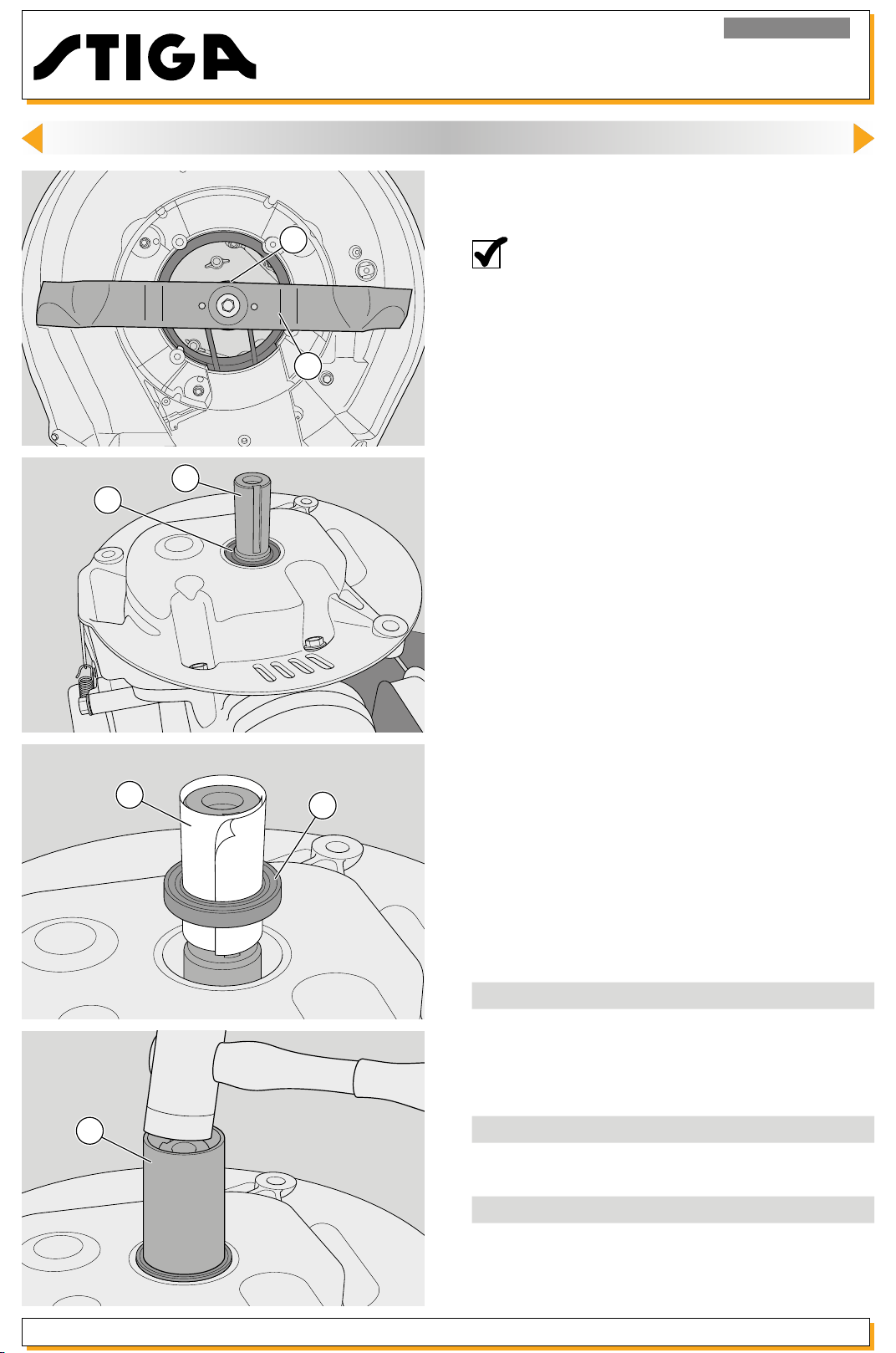
14.6. Replacing the lower compression ring of the
engine shaft (sump side)
27
NOTE - Before executing this operation di-
scharge all the oil from the bowl and rotate
180° the motor.
1 - Remove the blade (26) and hub (27).
26
29
30
28
2 - Take out the spline key (28).
3 - Use a thin screwdriver inserted under the sealing
lip to extract the oil seal ring (29).
4 - Make a paper tube (30) around the shaft to
protect the sealing lip and insert the new ring (31)
so that it enters its housing.
31
5 - Complete the insertion with the help of a pipe
(32) of a diameter of approximately 30-35 mm.
32
Service manual
page 48
Tightening torques
2 Spark plug tightening torque
6 Valve cover xing screws 7-9 Nm
13 Fan xing nut 60-70 Nm
19 Blow-by closure plate screw 7-9 Nm
Technical information
Inlet valve clearance
Exhaust valve clearance 0,15-0,20 mm
Special equipment
3 Compression testing tool
Release 00 - 03/2018
16-20 Nm
0,15-0,20 mm
Page 49

Engine RS100 - RSC100
<< BACK >>
15. ENGINE BLOCK - Overhauling internal parts
15.1. Removing the engine
1 - Empty the tank of fuel [ 5.1].
1
2 - Drain the oil in the sump by removing the ller
plug and turning the mower on its side.
3 - Disconnect the engine brake cable (1) and the
2
3
3
throttle cable (2) (
4 - Remove the blade assembly and undo the three
screws (3) which are accessible from the bottom
of the lawnmower.
RSC100).
Grasp the engine at points which offer a
secure grip, taking account of the overall weight
given in the relevant table
3
[ 3.2].
Release 00 - 03/2018
page 49
Service manual
Page 50

Engine RS100 - RSC100
<< BACK >>
15. ENGINE BLOCK - Overhauling internal parts
All the following operations on the grass cutter necessitate the removal of the motor.
5
4
6
6
15.2. Carter opening
1 - ( RSC100 model only) Remove the carburettor
[ 10.3].
2 - Loosen the lever xing nut (4), release the spring
(5) and remove the control lever.
3 - Position the engine on a stable support and
remove the sparkplug.
Bring the piston to the TDC (Top Dead Centre).
4 - Turn the engine upside down and place it with
the shaft pointing upwards.
5 - Loosen the seven screws (6) and remove the
engine sump with the help of levers in the two
points indicated.
6 - verify the phasing between the engine shaft
and the camshaft;
If necessary, re-set the phasing, referring to the
indications provided.
[ 8.1] and remove the lever support
7 - On assembly, follow the steps described in reverse and:
- clean the contact surfaces, removing any remaining silicone;
- evenly distribute the silicone seal (THREE BOND
1207) (7) as shown in the gure;
- ensure that the two centring pins (8) are properly
inserted;
- always
sump side
- close the screws (6) intersection lock bowl to the
indicated couple;
8 - After installing the engine on the machine:
7
8
8
- rell the sump and make sure that the ller plug
is tight.
-
check the adjustment of the brake cable
12.1]
model only).
9 - Following reassembly it is advisable to check the
engine’s peak rpm
10.2a] ( RS100) .
replace the compression ring from the
[ 14.6].
and the throttle cable
[ 10.2] ( RSC100) [
[ 10.1] ( RSC100
[
Service manual
page 50
Release 00 - 03/2018
Page 51

Engine RS100 - RSC100
<< BACK >>
15. ENGINE BLOCK - Overhauling internal parts
15.3. Dismantling and checking the camshaft and
counterweight governor
1 - Bring the piston to the TDC (Top Dead Centre).
9
(EX)
(IN)
2 - Open the crank case
3 - Remove the camshaft (9).
4 for wear and tear. Th
than 11,95 mm.
A
5 - Measure the cams (IN and EX) on the camshaft,
checking for wear. The value must not be lower
than 24,10 mm (IN) and 24,13 mm (EX).
6 - Check the regular movement of the pressure
reducer (10) and the efciency of the spring (11);
the whole group must always be replaced in the
case of breakage or irregular operation of the
pressure reducer.
Measure seat (A) of the camshaft, checking
[
15.2].
e value must not be lower
11
14
12
Release 00 - 03/2018
10
13
page 51
7 - Check that the irregolar centrifugal (12) that are
not present ruptures of the lubrication pallets.
8 - Turn the governor’s gears quickly and check that
the counterweights (13) expand correctly, causing
the pin (14) to be moved axially.
Service manual
Page 52

Engine RS100 - RSC100
<< BACK >>
15. ENGINE BLOCK - Overhauling internal parts
16
17
15
9 - In the case of breakage or irregular operation
of the counterweights the whole group, xed by a
plate (15) and a screw (16) must be replaced.
10 - When installing the new unit, take care to
position the washer (17) correctly on the opposite
side.
20
19
18
11 - Before tting the camshaft ensure that the two
tappets (18) are correctly housed in their seats.
12 - When retting the camshaft, maximum care
must be taken to match up the two references (19)
and (20) punched on the gears, so as to ensure
correct distribution phasing.
13 - During assembly, refer to the operations
in section
place the washer (7) between the sump and the
housing.
[ 15.2] always remembering to re-
Service manual
page 52
Release 00 - 03/2018
Page 53
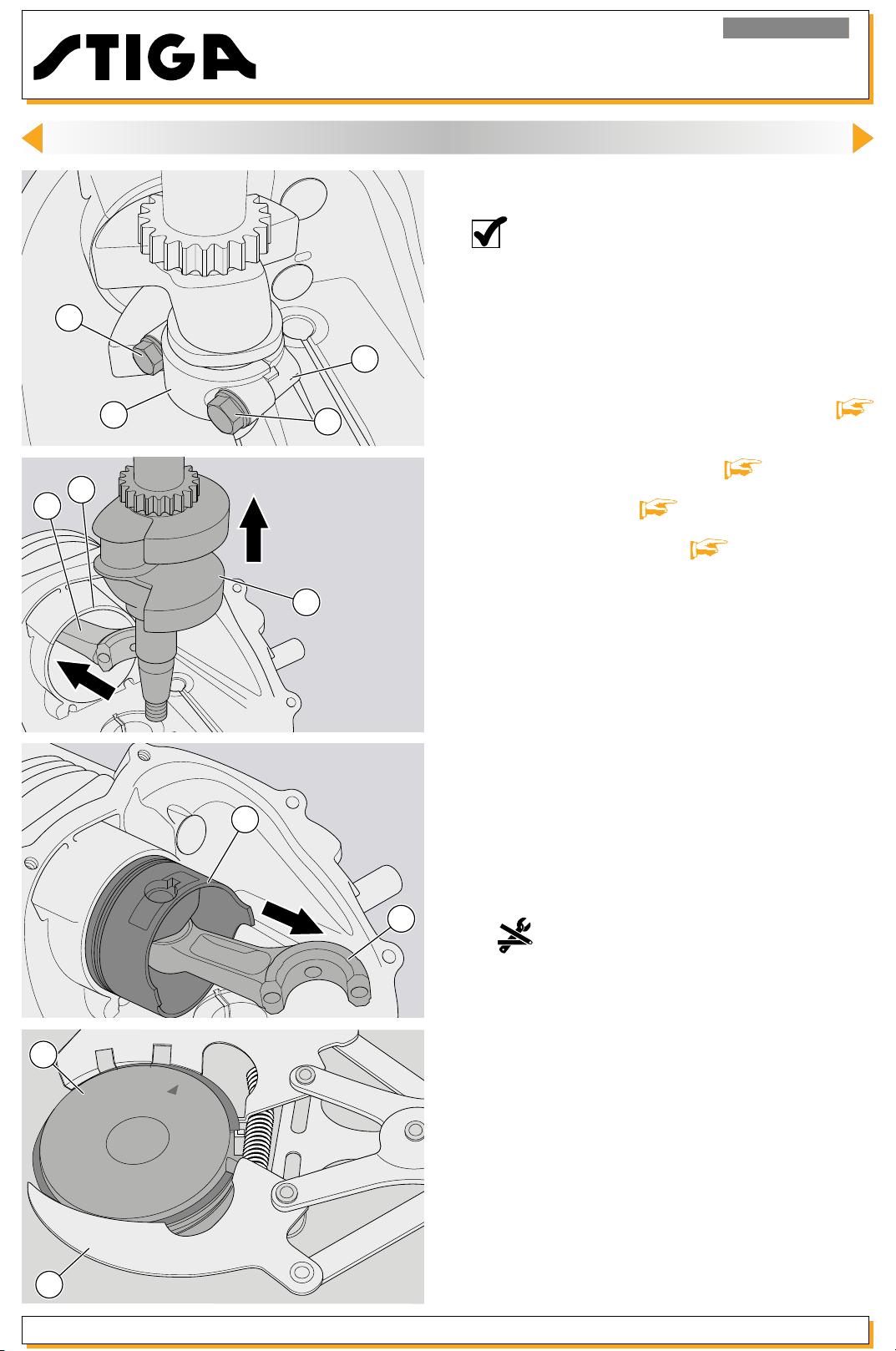
23
<< BACK >>
Engine RS100 - RSC100
15. ENGINE BLOCK - Overhauling internal parts
15.4. Dismantling and checking the piston, piston
rings, connecting rod and engine shaft
NOTA - These paragraphs describe all the
operations for checking and overhauling the
thermal components of the engine; it is left
to the operator to assess the advisability of
performing all the operations described or
22
only part of them, depending on the type of
engine problems encountered.
22
25
21
24
26
23
1 - Remove the engine from the machine
.
15.1]
2 - Remove the complete fan
3 - Open the cover
4 - Remove the camshaft
5- Dismantle the connecting rod (21) cap (22), xed
with two screws (23) (take note of any reference
marks for retting).
6 - Push the connecting rod (22) so as to ensure the
piston (24) enters the cylinder (25) fully.
7 - Pull the engine shaft (26) out completely.
8 - To remove the piston (24) pull the connecting
rod (22) as shown in the gure.
[ 15.2].
[ 14.3].
[ 15.3].
[
24
27
Release 00 - 03/2018
22
page 53
9 move the two compression rings and the oil scraper
ring from the piston (24).
10 - Carefully remove all carbon deposits from the
compression rings, the inside of the cylinder and
the piston head.
Use the special expanding tool (27) to re-
Service manual
Page 54

29
<< BACK >>
Engine RS100 - RSC100
15. ENGINE BLOCK - Overhauling internal parts
9 - To check the wear in the compression rings, insert
them one at a time into the cylinder (25) by about
10-15 mm and measure the gap between the two
ends with a feeler gauge (28); the rings must be
replaced if the gap is more than 0.8 mm.
NOTE - If a gap of more than 0.4 mm is measu-
28
10 - Use a section of an old ring (29) to carefully
clean the inside of the piston (24) ring housings, ensuring that the oil passage holes are not blocked.
red with new rings it means that the cylinder is
worn beyond the acceptable limits and must
be replaced. The cylinder must be replaced
if it shows striping due to a seizure.
24
32
30
31
11 - To check the wear in the piston ring housings,
t a new ring and measure the residual space with
a feeler gauge (30). The piston must be replaced
if it is greater than 0.12 mm in the two compression
ring housings.
12 - Use a screwdriver to remove the clamping ring
(31) and remove the gudgeon pin (32) from the
piston (24).
Service manual
page 54
Release 00 - 03/2018
Page 55
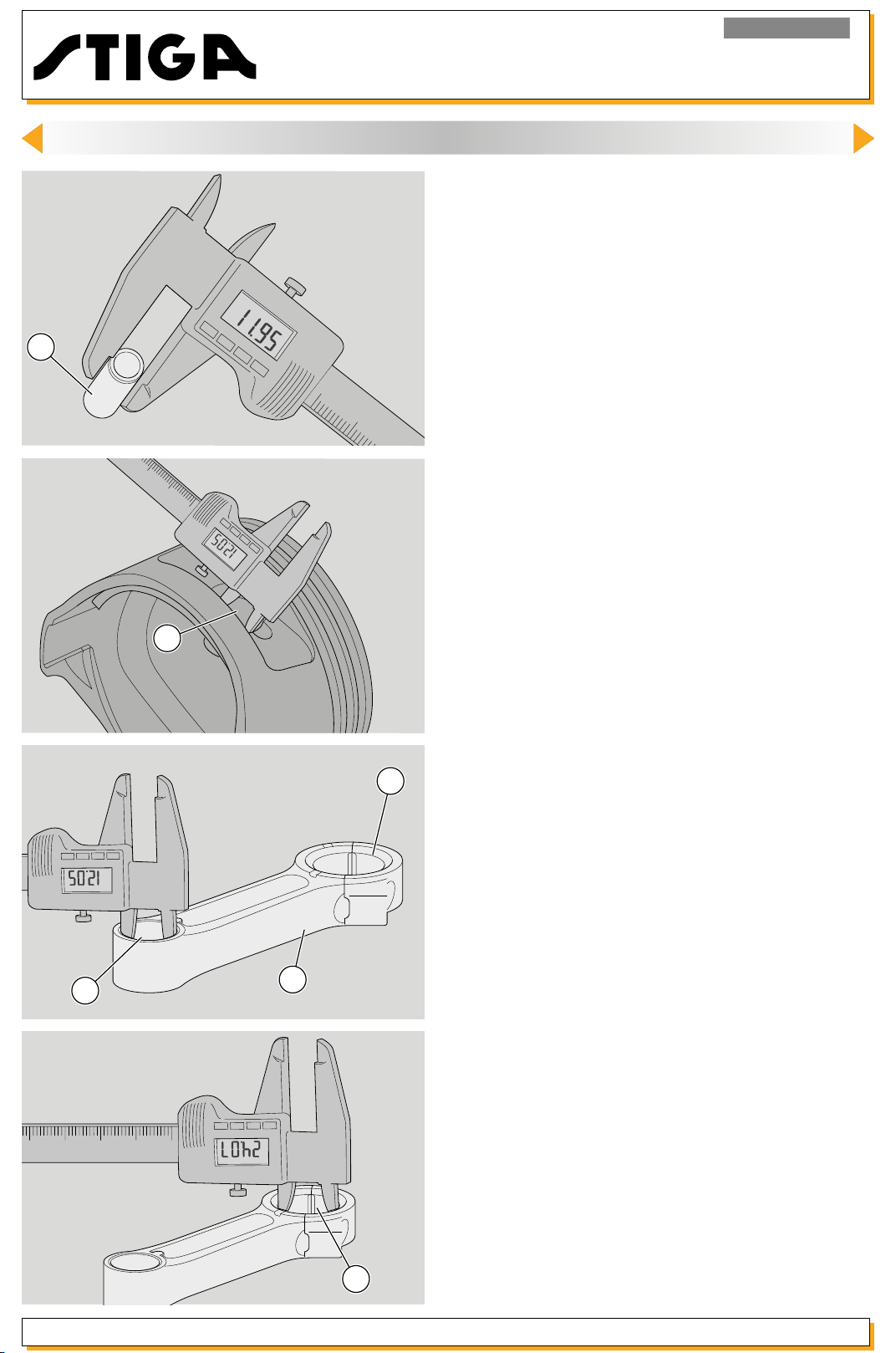
32
<< BACK >>
Engine RS100 - RSC100
15. ENGINE BLOCK - Overhauling internal parts
13 - Check the diameter of the gudgeon pin (32) in
several places and replace it if it is less than 11.95
mm, even at a single point.
14 - Check the diameters of the gudgeon pin housings (A) on the piston (24) and replace the piston
if they are more than 12.05 mm, even at a single
point.
A
15 - Fit the cap (21) to the connecting rod (22) and
21
B
22
check the diameter from the gudgeon pin side and
the crank side; replace the connecting rod if the
values are greater than:
B : 12,05 mm on the gudgeon pin side;
C : 24,07 mm on the crank side.
If the connecting engine shaft is outside measurement tolerances or has small scratches or marks, it
is necessary to replace it.
Release 00 - 03/2018
C
page 55
Service manual
Page 56

34
<< BACK >>
Engine RS100 - RSC100
15. ENGINE BLOCK - Overhauling internal parts
16 - On the engine shaft (26), removed beforehand,
use a digital gauge to check the diameter of the
connecting rod pin.
The value must not be less than 23.92 mm or the
26
90
10
80
20
30
70
40
60
50
33
engine shaft will have to b
e replaced.
NOTE - In the case of seizing, the manifolds
canbepolishedwithneemerycloth,only
removing foreign matter and checking that
thenalsizeremainswithintheaforementioned limit.
17 - To check the alignment between the manifolds and the protruding part of the shaft, place
the engine shaft on two prismatic guides (33) and,
with the help of a comparator (34) placed at the
end, check the displacement by rotating the shaft.
The shaft must be replaced if the displacement
exceeds 0.10 mm.
35
36
37
33
IMPORTANT: A bent shaft must never be re-
paired!
WARNING - DANGER: A bent shaft causes ab-
normal vibrations and could be dangerous
when the machine is used!
18 - To ret the rings to the piston, rst t the three
oil scraper rings (35), then the ring with a round
edge (36) and nally the ring with a sharp edge
(37), being careful over the markings (which must
face the piston head) and in arranging the gaps to
ensure that they are not aligned with each other;
D
Service manual
page 56
Release 00 - 03/2018
Page 57

Engine RS100 - RSC100
<< BACK >>
15. ENGINE BLOCK - Overhauling internal parts
24
31
32
31
22
19 - Fit the connecting rod (22), gudgeon pin (32)
and clamping rings (31) to the piston (2
NOTE - The marking on the piston must be
directed towards the intake.
The connecting rod must be mounted with
the marking (38) facing upwards.
4).
39
38
20 - Put the piston into the ring compression tool
(39).
21 - Oil the inside of the piston liberally and insert the
piston, with the marking facing the exhaust.
39
Release 00 - 03/2018
page 57
Service manual
Page 58

Engine RS100 - RSC100
<< BACK >>
15. ENGINE BLOCK - Overhauling internal parts
22 - Mount the engine shaft (26) and the connecting
rod cap (21) with the relative screws (23), taking
care with the position references (38) so as to avoid
inverting the mounting direction of the cap.
Close the screws (23) to the indicated couple.
23
21
23
20
19
38
23 - After having xed the connecting rod cap, take
the greatest care to ensure that the two position
references (19) and (20) punched on the engine
shaft and camshaft gears, coincide, ensuring the
correct distribution phasing.
24 - Close the carter and x the screws (6) to the
indicated couple
25 - Whenever the engine shaft is dismantled and
retted, it is always necessary to:
- replace the sealing ring on the fan side
;
14.5]
[ 15.2].
[
Service manual
6
page 58
- replace the sealing ring on the sump side
.
14.6]
26 - During assembly perform the operations
indicated in section
to replace the silicone gasket (7) between the sump
and the casing
[ 15.2] always remember
Release 00 - 03/2018
[
Page 59

Engine RS100 - RSC100
<< BACK >>
15. ENGINE BLOCK - Overhauling internal parts
15.5 Overhauling the valves
NOTE - These paragraphs describe all the
operations for checking and overhauling the
valves;
41
42
A
B
40
1 - Remove the starter assembly [
2 - Open the crank case
the piston
3 - Move the rocker arms (40); press down the spring
seal cap (41) and move it sideways to remove from
the valve stem (42).
IMPORTANT - The intake and exhaust valves are of
different sizes.
4 - Use an emery cloth to remove all incrustations
from the valve head and check the thickness of the
rim (A); the valve must b
is less than 0,6 mm or if it shows signs of burning.
lity of performing all the operations described
or only part of them, depending on the type
of engine problems encountered.
6.1].
[ 15.2] and remove
[ 15.4].
e replaced if the margin (A)
it is left to the operator to assess the advisabi-
5 - Check the diameter of stem (B) in several points
and replace the valve if it is less than the following,
even if only in one point:
5,45 mm (inlet - IN)
5,42 mm (exhaust - EX)
Release 00 - 03/2018
page 59
Service manual
Page 60

Engine RS100 - RSC100
<< BACK >>
15. ENGINE BLOCK - Overhauling internal parts
6 - Check the free length of the spring (43) and
replace the spring of it is less than 29,4 mm.
7 - When mounting:
43
44
- carefully clean the v
any foreign body;
- apply a lm of oil on the valve stems before inserting them in their respective housings;
- ensure the proper position of the intake valve and
exhaust valve, which can be notice by the different
sizes (Intake: larger, Exhaust: smaller).
8 - Replace the intake valves and check that the
oil seal (44) is in place.
alve guides and housings of
Service manual
page 60
Release 00 - 03/2018
Page 61
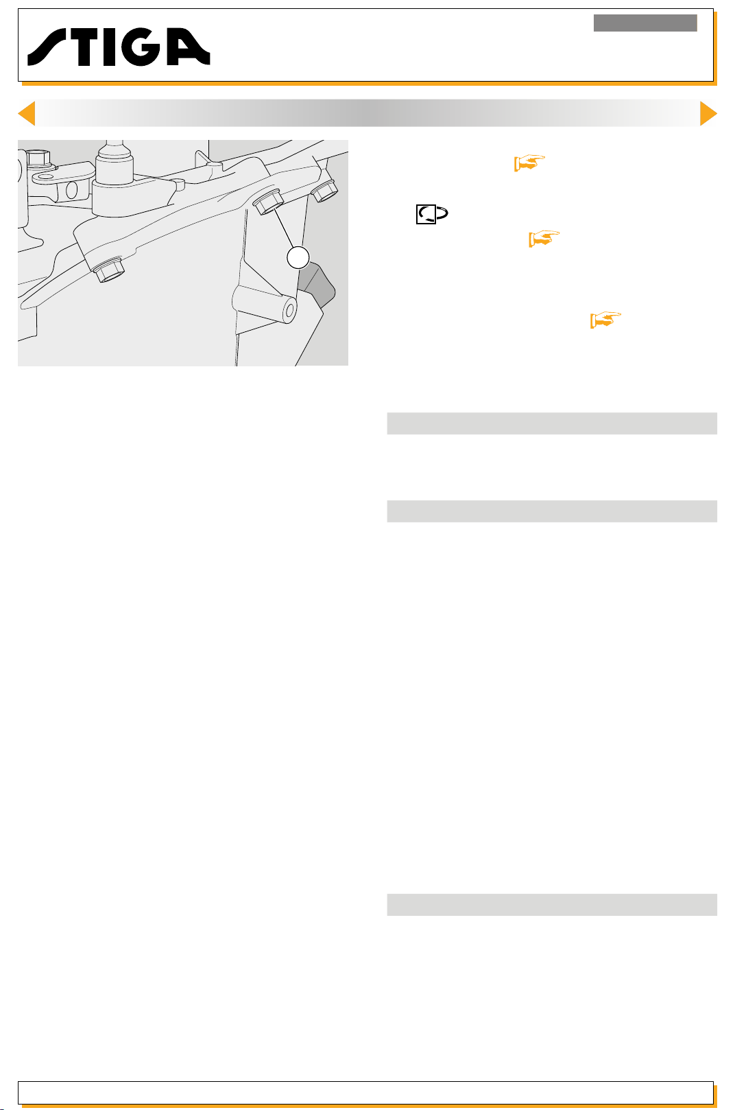
Engine RS100 - RSC100
<< BACK >>
15. ENGINE BLOCK - Overhauling internal parts
9 - Close the carter and x the screws (6) to the
indicated couple
[ 15.2].
10 indicated in section
6
to replace the silicone gasket (7) between the sump
and the casing.
11 - Ret the starter assembly
Tightening torques
6
17
28
Technical information
Oil sump capacity 0,40 litri
Diameter aspiration cam 24.1 mm
Diameter discharge cam 24,13 mm
Maximum segments gap in the cylinder 0,8 mm
Max. compression ring axial gap
Minimum gudgeon pin diameter 11,95 mm
Max. gudgeon pin housing diameter
on piston
Max. connecting rod diameter
Diam. connecting rod’s pin on engine shaft
Verify the engine shaft extremes 0,10 mm
Minimum inlet valve stem diameter 5,45 mm
Minimum exhaust valve stem diameter 5,42 mm
Valve head margin min. thickness 0,6 mm
Minimum valve spring length 29,4 mm
Special equipment
28
40 Piston ring compressing tool
During assembly perform the operations
[ 15.2] always remember
[ 6.1].
Union screws under carter and sump
Counterweight governor xing screw
Fixing screws lower connecting rod cap
gudgeon pin side
crank side 24,07 mm
Piston ring removal expander
8-12 Nm
8-12 Nm
11-13 Nm
0,12 mm
12,05 mm
12,05 mm
23,92 mm
Release 00 - 03/2018
page 61
Service manual
Page 62

Engine RS100 - RSC100
<< BACK >>
16. TROUBLESHOOTING
PROBLEM CAUSE SOLUTION
The engine does not start or
starts badly
The engine brake cable is faulty or
unfastened
The OFF microswitch is faulty
Coil earth connection
Earth wire is attened
The coil is faulty and does not supply
current or the air gap is too large
Carburettor dirty
Poor seal of carburettor needle valve
Choke blocked /not closed (
RSC100)
Adjust and/or replace the cable
[
12.1]
Replace the whole shut-down group
[
12.2]
Check electrical cabling of earth wire
[
11.1]
Replace the whole shut-down group
[ 12.4]
Check coil
Check and clean the carburettor
[
[ 9.1] ( RS100)
and
Clean the carburettor housing and
needle valve [ 8.1] ( RSC100)
[ 9.1] ( RS100) or repla-
and
ce the carburettor
RSC100) and
Check and clean the carburettor
and the choke
[ 11.2]
8.1] ( RSC100)
[ 8.2] (
[ 9.2] ( RS100)
[
8.1]
Startingisdifcultandstrains
the rope
The spark plug is badly connected
or faulty
Blocked air lter
Valve malfunction
Insufcient pressure
The Primer is faulty ( RS100)
Presence of oil in the combustion
chamber
Pressure reducer fault
Check spark
spark plug
Execute the lter cleaning
and [ 7.1a] ( only for RS100)
Check the valve clearance
[
14.2]
Check tightness of cylinder head
screws, replace washer if necessary.
Check wear and tear of the piston
[
rings
Check the effective operation of the
Primer
Clean the combustion chamber
Check the pressure reducer and
counterweights
15.4]
11.1] or replace
[
[
15.3]
[ 7.1]
Service manual
page 62
Release 00 - 03/2018
Page 63

Engine RS100 - RSC100
<< BACK >>
16. TROUBLESHOOTING
PROBLEM CAUSE SOLUTION
The engine starts but does
not run
Theengineisinefcientor
the runs irregularly
The tank cap has a clogged breather
pipe
Insufcient pressure
Exhaust is blocked
The throttle cable is not well adjusted
RSC100)
(
The governor malfunctions or there is
a problem with the rods
Air seepage in the carburettor
Carburettor dirty
Insufcient pressure
Clean and/or replace the cap
[
5.3];
Check correct valve operation [
.
Check that the spark plug is
15.5]
secured
cracks in the casing. Ch
tear of the piston rings
Check that there is airow through
the exhaust system and replace if
necessary
Check and/or adjust the throttle cable [ 10.1]
Check the entire governor system
[ 10]
Replace the carburettor gaskets
[ 8.1] ( RSC100)
and
Check and clean the carburettor
[ 8.1] ( RSC100)
and
Check correct valve operation [
15.5]
secured
cracks in the casing.
tear of the piston rings
[ 11.1].
[
[ 9.1] ( RS100)
[ 9.1] ( RS100)
.
Check that the spark plug is
[ 11.1].
Check for any
eck wear and
[ 15.4]
13.1]
Check for any
Check wear and
[ 15.4]
The engine overreved
The engine judders
The coil air gap has been poorly
adjusted
Oxidation or loosening of spark plug
connections
Governor blocked due to breakage
of centrifugal assembly or breakage
of external governor springs.
It is possible that the governor is dirty
Engine screws loose Tighten the screws
Engine shaft off-centre
Engine timing faulty
Adjust the air gap
the problem persists, replace the coil
[ 11.3]
Perform spark test
place spark plug
Check the entire governor system
[
10 and 15]
Replace the engine shaft
Check wear and tear of the connecting rod of the engine shaft, replace
shaft if necessary
11.2] and if
[
[ 11.1] or re-
[ 15.4]
[
15.4]
Release 00 - 03/2018
page 63
Service manual
Page 64

Engine RS100 - RSC100
<< BACK >>
16. TROUBLESHOOTING
PROBLEM CAUSE SOLUTION
The engine does not turn off
The engine does not stop
within 3 seconds after it has
turned off
The engine uses a lot of oil
The engine brake cable is bent or
jammed
The earth cable is disconnected or
broken
Faulty or no clutch lining
Faulty blow-by operation
Poor piston ring seal
Excessive gap between the guide
and the inlet valve stem
Ring assembly error
Check and/or adjust the cable
[
12.1]
Check and/or replace oil breather
[
tab
Replace the engine stopping system
[ 12.4]
Check and/or replace the blow-by
system
dition of the air lter
Replace the rings
Check and/or replace the valve
[
Check the assembly of the rings
[
[
15.5]
15.4]
11.1]
14.4]. Check the con-
[ 7.1]
15.4]
[
Service manual
page 64
Release 00 - 03/2018
Page 65

Engine RS100 - RSC100
<< BACK >>
Release 00 - 03/2018
page 65
Service manual
 Loading...