

Page 1

STIGA PARK
PRO 18
PRO 16
PRESIDENT
CLASSIC
8211-0211-06
Page 2
7. Park Classic-President 11.
8. Park Pro16-Pro18
9. Park President
10. Park Pro16-Pro18
12. Park Classic-President
13. Park Pro16-Pro18
14. Park President
Page 3
15. Park Pro16-Pro18
20. Park Pro16-Pro18
16. Park Pro16-Pro18
17.
19. Park Classic-President
21. Park Classic-President
18.
22. Park Pro16-Pro18
23.
Page 4
27. Park President-Pro16-Pro18
31. Park President
28. Park Classic-President
29. Park Classic
30. Park Classic 34.
32. Park Pro16-Pro18
33. Park Pro16-Pro18
Page 5
24. Park Classic
25. Park President
26. Park Pro16-Pro18
Page 6
9
1
11
10
4
1. Park Classic
3. Park President-Pro16
8
2
9
1
13
2. Park Classic
11
3
7
12
15
2
14
7
19
13
16
6
85
9
4. Park President-Pro16
3
17
18
12
14
15
20
5. Park Pro18
5
6. Park Pro18
11
2
13
3
Page 7

GB
ENGLISH
GENERAL
This symbol indicates WARNING. Personal injury and/or damage to property
may result if the instructions are not
followed carefully.
You must read these instructions for
use and the accompanying pamphlet
"SAFETY INSTRUCTIONS" carefully before starting up the machine.
SYMBOLS
The following symbols are displayed on the machine in order to remind you about the safety precautions and attention necessary when using the
machine.
The symbols mean:
Warning!
Read the instruction book and safety manual before using the machine.
Warning!
Beware of objects being flung out. Keep
spectators away.
Warning!
Always use hearing protectors (earplugs
or muffs).
Warning!
This machine is not designed to be driven
on public roads.
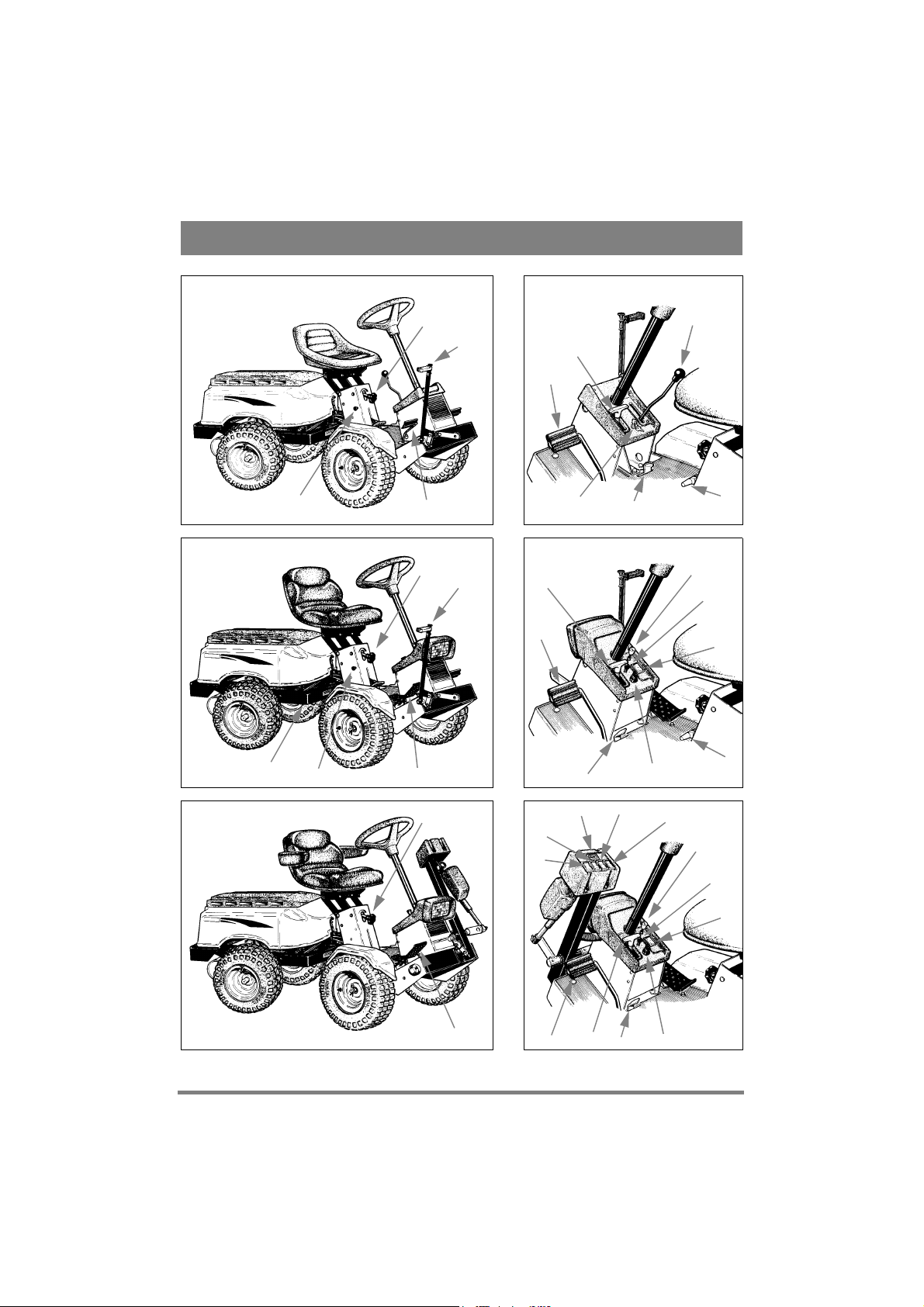
CONTROLS
Items 1 - 20, see figures 1 - 6.
1. IMPLEMENT RAISING LEVER (not
Pro18)
A lever for raising front-mounted accessories to the
transport position.
2. SERVICE BRAKE
A pedal that acts on the machine's braking system.
There are two positions:
1. Pedal released - service brake
not activated.
2. Pedal fully depressed - service
brake fully activated. (PresidentPro: forward drive also released.
Classic:
The engine is provided with automatic governor
control. This means that the engine speed increases
under load. For this reason, you must disengage the
forward drive before braking the machine.
Press both the brake and clutch pedals when you
want to brake or stop the machine. Never brake the
machine without first de-clutching
3. PARKING BRAKE
An inhibitor that can lock the brake pedal in the depressed position.
Depress the brake pedal fully. Move the
brake inhibitor to one side and then release
the brake pedal.
The parking brake is released by pressing the brake
pedal lightly. The spring-loaded inhibitor slides to
one side.
Make sure the parking brake is released when operating the machine.
4. CLUTCH (Classic)
A pedal used for engaging and disengaging the
drive to the mechanical gearbox. Two positions:
1. Pedal released - forward drive
engaged. The machine will move
if a gear is engaged.
2. Pedal depressed - forward
drive released, gearshifting can
be performed.
NOTE! You must never regulate the operating
speed by slipping the clutch. Use a suitable gear instead so that the right speed is obtained.
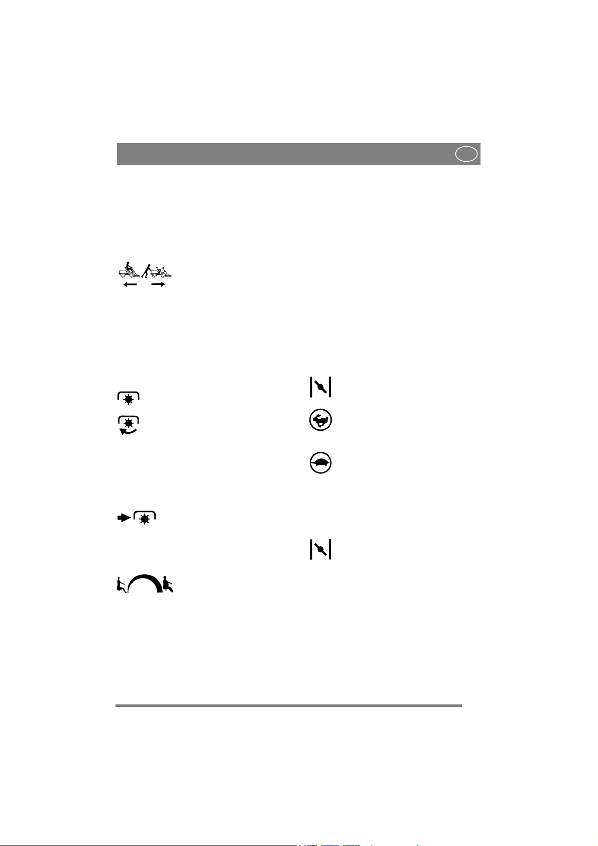
5. DRIVE PEDAL (President - Pro16 Pro18)
A pedal that activates the variable transmission.
1. Depress the pedal with the ball
of the foot - the machine moves
forwards.
2. No load on the pedal - the machine is stationary.
3. Depress the pedal with the heel
- the machine reverses.
The speed is regulated by the drive pedal. The more
pressure applied, the faster the machine will move.
Page 8
ENGLISH
GB
6. DISENGAGING LEVER (President Pro16 - Pro18)
A lever for disengaging the variable transmission.
Enables the machine to be moved by hand without
the help of the engine. (Note that, on the Pro16Pro18, the lever is on the left-hand side.) There are
two positions:
1. Lever moved back - transmission engaged for normal operation.
2. Lever moved forward - transmission disengaged. The machine can be moved by hand.
To avoid damage to the transmission, do not tow the
machine for any great distance.
7. POWER TAKE OFF - IN (not Pro18)
A lever for engaging the power take-off for driving
front-mounted accessories. There are two positions:
1. Lever in lower position - power take-off
disengaged.
2. Lever in upper position - power take-off
engaged. The lever is locked in this position if a person weighing more than 30 kg
is sitting on the seat.
8. POWER TAKE OFF - OUT (not
Pro18)
A spring-loaded lever for disengaging the power
take-off.
Press the button to disengage the
powertake-off.
9. SEAT SUSPENSION
Rotary control for variable adjustment of the seat
suspension. Adjust to weight of driver.
1. Turning counter-clockwise suspension will become softer.
2. Turning clockwise - suspension will become harder.
If the suspension is tightened too hard it could
mean that the lever for engaging the power takeoff (7) cannot be locked in its upper position.
NOTE! To prevent a deterioration in mobility,
do not over tighten the screw joints in the seat
suspension.
10. GEAR LEVER (Classic)
A lever for selecting one of the five forward gears
in the gearbox (1-2-3-4-5), neutral (N), or reverse
(R).
The clutch pedal must be kept depressed when
changing gear.
NOTE! You must make sure the machine is quite
stationary before changing from reverse to forward
gear or vice versa. If a gear does not engage immediately, release the clutch pedal and depress it
again, and then engage the gear once again. Never
force a gear in.
11. THROTTLE/CHOKE CONTROL
A control for setting the engine speed and to choke
the engine when starting from cold. (The latter
does not apply to Pro16-Pro18, which has a separate choke control - see item 12).
1. Choke - for starting a cold engine.
Choke located in top of groove (does not
apply to Pro16-Pro18).
2. Full throttle - when the machine is in
operation, full throttle should always be
used. Full throttle positioned 1 - 1.5 cm
from the top edge of the groove.
3. Idle.
12. CHOKE CONTROL (Pro16 Pro18)
A pull-type control to choke the engine when starting from cold.
1. Control fully pulled out - choke valve in
carburettor closed. For starting cold engine.
2. Control pushed in - choke valve open.
For starting warm engine and when operating the machine.
Never operate the machine with the choke pulled
out when the engine is warm.
13. STARTER KEY
An ignition key used for starting and stopping the
engine. There are three positions:
1. Stop position - engine short circuited.
STOP
The key can be be removed.
Page 9

GB
ENGLISH
2. Drive position (without symbol).
3. Start position - the electric starter motor
START
is activated when the key is turned to the
spring-loaded start position. Once the engine has started, allow the key to return to
the drive position.
A spare key is enclosed in the plastic bag that also
includes this "instructions for use". Keep this key
in a safe place.
14. CRUISE CONTROL (Pro16 Pro18)
A switch for activating the cruise control. The
function of the cruise control allows the drive pedal (5) to be locked in the desired position. You do
not need to use the right foot.
1. Depress the drive pedal until the desired
speed is achieved. Then press the rear part
of the switch to activate the cruise control.
The symbol will light up green.
2. Disengage the cruise control by pressing the front part of the switch.
15. LIGHT SWITCH (not Classic)
A pull-type switch for the halogen headlamp. The
headlamp works only when the engine is running there is no load on the battery. There are two positions:
1. Switch pulled out - headlamp "on".
2. Switch pushed in - headlamp "off".
16. POWER TAKE OFF (Pro18)
Circuit-breaker for engaging and disengaging the
electromagnetic power take-off.
1. Press the lower part of the circuit-breaker - the power take-off will be engaged.
The symbol will indicate green.
2. Press the upper part of the circuit-breaker - the power take-off will be disengaged.
17. HOUR METER (Pro18)
Indicates the number of operating hours. Works
only when the engine is running.
18. ELECTRIC LIFTER (Pro18)
Switch (red symbol) for controlling the frontmounted, electric lifter.
1. Press the upper part of the switch - the lifter will
be lowered to the working position.
2. Press the lower part of the switch - the lifter will
be raised to the transport position.
19. EL. CUTTING HEIGHT ADJUSTMENT (Pro18)
The machine has been designed for electrical adjustment of the cutting height (available as an accessory).
A connection plug is located on the right hand side,
in front of the front wheel.
The switch (orange symbol) is used to adjust the
cutting height up or down in continuously variable
positions.
20. REAR RAKE (Pro18)
The machine has been designed for the use of a
rear rake, which can be raised and lowered electrically (available as an accessory).
Connection cables are located at the rear of the machine, under the solenoid.
The switch (blue symbol) is used for raising or
lowering the rear rake.
OPERATING THE MACHINE
AREAS OF USE - PARK
The machine may only be used for the following
tasks using the STIGA accessories stated:
1. Mowing
Using mower deck 13-2922 (100B), 13-2913
(102M), 13-2917 (110S), 13-2915/13-2921
(121M) or flail mower 13-1977.
2. Sweeping
Using brush unit 13-1933 or collector brush
unit 13-1939. Use of dust guard 13-1936 is recommended with the first option.
3. Snow clearance
Using snow blade 13-1916 or snow thrower
13-1948. Snow chains 13-1956 and wheel
weights 13-1982 are recommended.
4. Grass clipping and leaf collection
Using towed collector 13-1978 (30") or
13-1950 (42").
Page 10

ENGLISH
GB
5. Grass and leaf transport
Using dump cart 13-1979 (Standard) or
13-1988 (Maxi).
6. Fertiliser spreading
Using fertiliser spreader 13-1987. Can also be
used for spreading grass seed.
7. Sand spreading
Using sand spreader 13-1975. Can also be used
for spreading salt. Snow chains 13-1956 and
wheel weights 13-1982 are recommended.
8. Weeding on gravel paths
Using front mounted hoe 13-1944 and rear
mounted rake 13-1969.
9. Lawn edge trimming
Using edge trimmer 13-1972.
10.Moss scarification
Using flail mower 13-1977 equipped with
special moss scarifier 13-1986.
The maximum vertical load on the towing hitch
must not exceed 100 N.
The maximum over-run load on the towing hitch
from towed accessories must not exceed 500 N.
GENERAL
You can fill with fuel and check the oil level in the
engine by removing the engine cover. You do this
by lifting it upwards and backwards (fig 34).
NOTE that, to check the oil level on the Pro16Pro18 models, you must remove the entire engine
casing.
Do not use the machine without first fitting the engine casing, otherwise there
is a risk of burn injuries or crushing accidents.
FILLING THE FUEL TANK
Always use lead-free petrol. Never use
oil-mixed petrol.
NOTE! Bear in mind that petrol is a perishable, do
not purchase more petrol than can be used within
30 days.
Petrol is highly inflammable. Always
store petrol in containers that are made
specially for this purpose.
Fill or top up with petrol only outdoors,
and never smoke when filling or topping up. Fill with petrol before starting
the motor. Never remove the filler cap
or fill with petrol while the motor is
running or still warm.
CHECK THE ENGINE OIL LEVEL
On delivery the crankcase is filled with SAE 30
oil.
Check the oil level every time before using to
ensure it is correct. The machine should be
standing on level ground.
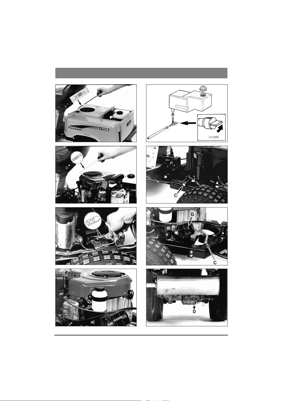
Wipe clean round the oil dipstick, remove
it and wipe off. Push down the dipstick
fully and screw it in.
Then unscrew it and pull it up again. Read off the
oil level. Top up with oil to the “FULL” mark if the
level comes below it (fig 7 - 8).
CHECKING THE TRANSMISSION
OIL LEVEL (President- Pro16 Pro18)
The transmission is filled with SAE 20W-50 oil
when the machine is delivered from the factory,
Check the oil level every time before using to
ensure it is correct. The machine should be
standing on level ground.
President:
Unscrew the oil dipstick (fig 9). Read off the oil
level. It should be within the xx markings.
Pro16-Pro18:
Read off the oil level in the reservoir (fig 10). It
should be between the MAX and MIN marks.
If necessary, top up with SAE 20W-50 oil.
It is important that you observe cleanness when handling oil for the transmission. There must not be any particles of
dirt in the system as dirt can easily
cause total failure of the transmission.
SAFETY SYSTEM
This machine is equipped with a safety system that
consists of:
- a switch on the gear box (only Classic)
- a switch at the brake pedal
- a switch in the seat mounting
- a switch at the power take-off engagement
Page 11

GB
ENGLISH
lever (only US and Canada)
In order to start the machine the following are necessary:
- gear lever in neutral (only Classic)
- brake pedal depressed
- driver sitting on seat
- power take-off engagement lever at lowest
setting (i.e. power take-off disengaged)
Always check the operation of the safety system before using the machine!
Check in the following way:
- start the engine, sit on the seat, select a gear,
lift your weight off the seat - the engine must
stop (applies to Classic)
- start the engine, sit on the seat, press the drive
pedal so that the machine starts to move, release
the drive pedal - the machine must stop (applies
to President)
- start the engine, sit on the seat, press the drive
pedal so that the machine starts to move, engage
the cruise control, lift your weight off the seat the machine must stop (applies to Pro16 Pro18)
- start the engine, sit on the seat, press the drive
pedal so that the machine starts to move, engage
the cruise control, press the brake pedal - the
machine must stop (applies to Pro16 - Pro18)
- start the engine, sit on the seat, engage the
power take-off, lift your weight off the seat - the
power take-off must be disengaged (all models)
Do not use the machine if the safety system does not work! Take the machine to
a service agent for inspection.
STARTING ENGINE
1. Open the fuel cock (fig 11).
2. Make sure that the sparking plug cable is prop-
erly in place.
3. Check to make sure the power take-off is en-
gaged.
4a. Classic:
Put the gear lever in neutral.
4b. President-Pro16-Pro18:
Do not keep your foot on the drive pedal.
5a. Classic-President:
Starting cold engine - put the throttle control in the
choke position. Starting warm engine - put the
throttle control at full throttle (1 - 1.5 cm below the
choke position).
5b. Pro16-Pro18:
Put the throttle control at full throttle. Starting cold
engine - pull the choke control out fully. Starting
warm engine - do not touch the choke control.
6. Depress the brake pedal fully.
7. Turn the starter key and start the engine.
8a. Classic-President:
Once the engine has started, move the throttle control gradually to full throttle if the choke has been
used.
8b. Pro16-Pro18:
Once the engine has started, push the choke control
in gradually if it has been used.
9. When starting from cold do not make the machine work under load immediately, but let the motor run for some minutes first. This will allow the
oil to warm up.
STOPPING
Disengage the power take-off and apply the parking brake.
Allow the engine to idle for 1 - 2 minutes. Stop the
engine by switching off the ignition key.
Shut off the petrol cock. This is particularly important if the machine is to be transported on a trailer,
for example.
If the machine is left unattended to, remove the lead from the spark plug. Also
remove the starter key.
The engine may be very warm immediately after it is shut off. Do not touch the
silencer, cylinder or cooling flanges as it
can cause burns and injury.
Machines with catalytic converters:
The catalytic converter gets very hot during operation. The heat remains for a long time after the engine has been stopped.
Avoid risk of fire:
- do not park in close proximity to inflammable
objects.
- do not cover the machine until the catalytic converter has cooled down.
OPERATING
Make sure that there is the correct quantity of oil in
the engine when driving on slopes (oil level on
Page 12
ENGLISH
GB
“FULL”).
Be careful when driving on slopes. No
sudden starting or stopping when moving up or down a slope. Never drive
across a slope. Move from the top and
down, and from down to the top.
The machine, equipped with original
accessories, must not be driven on
slopes greater than 10° in any direction.
Reduce the speed on slopes and when
moving the machine in sharp bend-like
patterns to prevent the machine from
turning over or you losing control over
the machine.
NOTE! Before using a trailer, contact your insurance company.
NOTE! This machine is not designed to be driven
on public roads.
Do not turn the steering wheel to full
lock when driving in top gear and with
full throttle as the machine can easily
topple over.
Keep hands and feet well away from the
articulated steering joint and seat
bracket to avoid having them squeezed.
Never operate the machine without the
engine casing.
When in operation always run the engine at full
throttle.
MAINTENANCE
No service should be carried out on the
machine unless:
- the engine has been stopped
- the ignition key has been removed
- the spark plug cable has been removed
from the sparking plug
- the parking brake is applied
- the power take-off is disengaged
CLEANING
To reduce the risk of fire:
- keep the engine, silencer, battery and
fuel tank free from grass, leaves and oil.
- regularly check the machine for oil
and/or fuel leakage.
NOTE! When washing the machine with water un-
der high pressure, do not point the jet directly at the
transmission.
CHANGING ENGINE OIL
Classic-President:
Change the oil for the first time after 5 hours running and then after every 50 hours running or once
a year. Change oil when the engine is warm.
Always use a good grade of oil (service grade SE,
SF or SG).
Pro16-Pro18:
Change the oil for the first time after 8 hours running and then after every 50 hours of running or
once a month. Change oil when the engine is
warm.
Always use a good grade of oil (service grade SE,
SF or SG).
Classic-President-Pro16-Pro18:
Change the oil after every 25 hours of running, or
once a week if the motor has to operate under demanding conditions or if the ambient temperature
is high.
The engine oil may be very warm if it is
drained off directly after the engine is
shut off. Therefore, allow the engine to
cool a few minutes before draining the
oil.
1. Screw out the oil drain plug C (fig 12 - 13). Let
the oil run out into a collection vessel. Do not allow oil to get on the v-belts.
2. Screw in the plug again.
3. Remove the dipstick and fill up with new oil.
Oil Capacity:
Classic - 1,4 litres
President - 1,4 litres
Pro16, Pro18 - 1,4 litres, when the oil filter is not
replaced. 1,7 litres, when the filter is replaced.
Oil type summer: SAE-30
(SAE 10W-30 can also be used. However, oil consumption may increase somewhat if 10W-30 is
used. Therefore check the oil level more regularly
if you use this type of oil).
Oil type winter: SAE 5W-30
(if this oil is not available, use SAE 10W-30).
Use oil without any additives.
Do not fill too much oil as this can result in overheating of the engine.
Page 13

GB
ENGLISH
Check the oil every time when topping up. The
level should come up to the “FULL” mark.
CHANGING THE TRANSMISSION
OIL (President - Pro16 - Pro18)
Change the oil the first time after 50 hours of operation, and then after every 250 hours or operation
or once a season.
Use a good grade of SAE 20W-50 oil (service
grade SE, SF or SG).
Total amount of oil:
President - 1.6 litres
Pro16, Pro18 - 3.3 litres
NOTE that the design of the transmission permits only about 80% of the total amount of oil
to run out when the oil is changed.
After filling the transmission with oil, the oil
which is left in the transmission mixes with the
new oil.
You should, therefore, not pour in too much oil
when you change the oil. Check the oil level several times while filling.
It is important that you observe cleanness when handling oil for the transmission. There must not be any particles of
dirt in the system as dirt can easily
cause total failure of the transmission.
President:
1. Unscrew the oil drain plug D. This is located to
the right as viewed from the rear (figs 14 and 25).
Allow the oil to run out into a collection vessel.
2. Screw the oil drain plug back into place.
3. Remove the oil dipstick and top up with new oil.
Pro16-Pro18:
1. Remove the oil reservoir cover (fig 10).
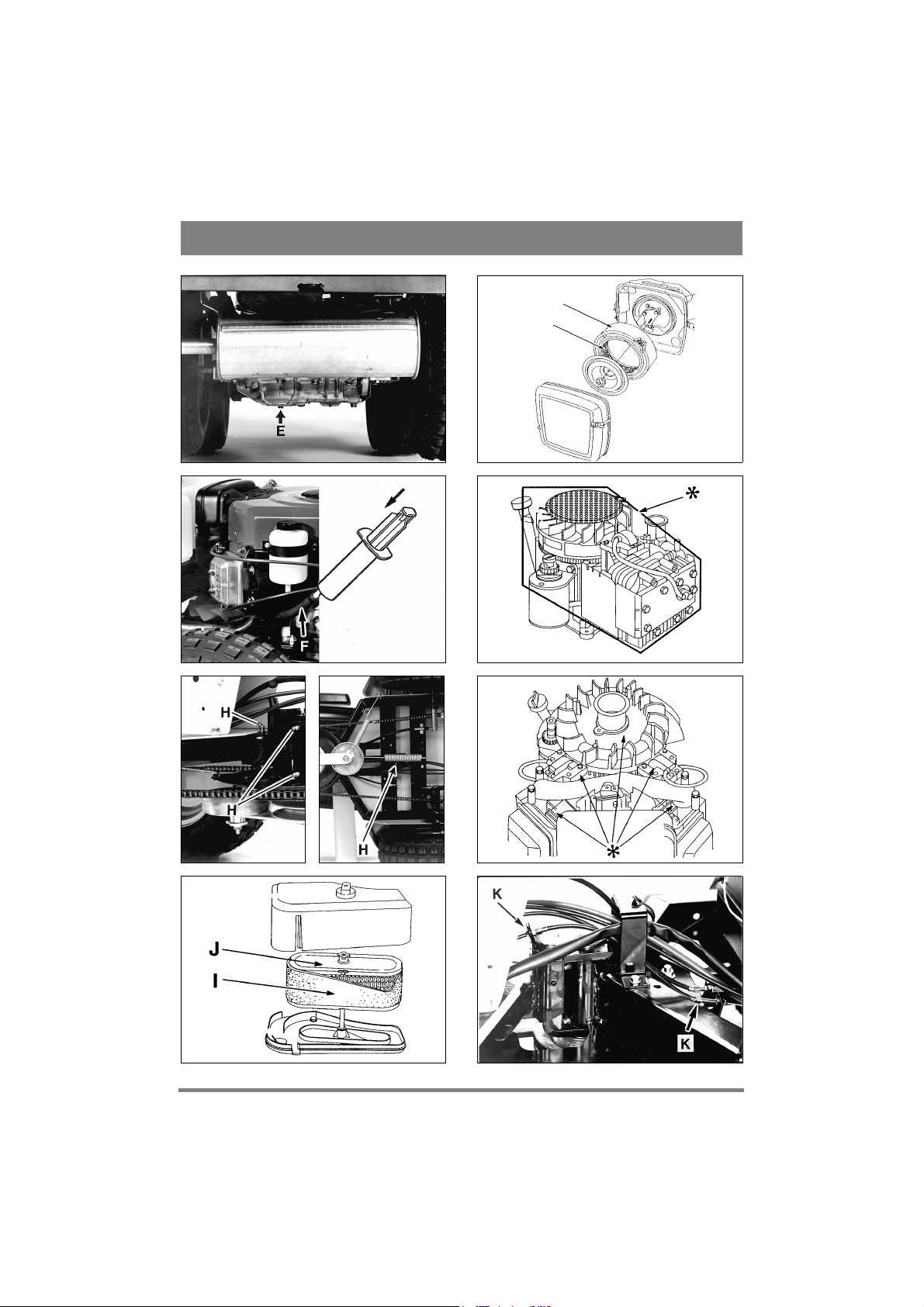
2. Unscrew the oil drain plug E. This is located to
the left as viewed from the rear (figs 15 and 26).
Allow the oil to run out into a collection vessel.
3. Screw the oil drain plug back into place.
4. Remove hose F from the lower side of the oil
reservoir (fig 16).
5. To facilitate filling up the oil, we recommend
that you use, for example, a pump (figure 16 shows
a STIGA pump, part number 1134-3898-01).
6. Fill the pump with oil. Then insert the nipple
into the hose F and slowly press the oil into the
transmission.
7. Connect the hose to the oil reservoir.
8. Finally, fill the oil reservoir with oil.
AIR BLEEDING (President - Pro16 Pro18)
After filling with oil, it may be necessary to bleed
the transmission.
1. Raise the rear part of the machine to enable the
drive wheels to rotate freely.
2. Start the engine and allow it to idle.
3. Press the drive pedal down forwards and back-
wards alternately.
4. When the drive wheels start to rotate, lower the
machine down onto its wheels.
5. Push the machine backwards while pushing the
front part of the drive pedal down. Then push the
machine forwards while pushing the rear part of
the drive pedal down.
6. When the machine starts to move, put the throt-
tle control at full throttle.
7. Start and stop the machine rapidly until its speed
is normal.
Remarks: Initial bleeding can be made as early as
when filling with oil. While filling, rotate the
transmission's belt pulley by hand.
REPLACING ENGINE OIL FILTER
(Pro16 - Pro18)
Replace the oil filter after every 100 hours of operation.
Before screwing the new filter securely into place,
oil the filter gasket with motor oil.
Screw the filter G securely by hand until the filter
gasket touches the filter attachment. Then tighten
three-quarters of a full turn (fig 13).
Start the engine and run it for 30 seconds. Then
switch off the engine. Check the oil level. If the oil
level is below the “FULL” mark on the dipstick,
top up with oil.
Start the engine and check for any oil leakage.
LUBRICATION
The machine has four grease nipples H which
should be lubricated with universal grease every
Page 14

ENGLISH
GB
25 hours running (fig 17 - 18).
All plastic bearings should be lubricated twice
each season.
Apply universal grease to the steering chain a cou-
ple of times each season. If the steering chain is really dirty, dismantle it, wash it, and then grease it
once more.
Apply a coating of engine oil to the tension arm
joints twice each season.
Apply a few drops of engine oil on both ends of the
throttle control cable a couple of times a season.
Classic:
The transmission is filled with oil (SAE 80W-90)
on delivery from the factory. If it is not opened
(which must only be done by a specialist), no topping up with oil should normally be done.
BATTERY
Check the acid level regularly.
The acid level should be between “UPPER” and
“LOWER” on the battery. When adjusting the level only use distilled water (battery water).
The battery acid is extremely corrosive
and can cause burns and injury to skin
and clothing. Always use rubber gloves,
and glasses (goggles) to protect the eyes.
Avoid inhaling any acid vapour.
Do not incline the battery too much so
that the battery acid can run out on to
hands or clothing. If this should happen, flush with lots of water.
If the battery terminals are coated with oxide they
should be cleaned. Clean the battery terminals with
a wire brush and grease them.
AIR FILTER
Clean the foam pre-filter I every 3 months or after
every 25 hours of operation, whichever comes
first.
Clean the paper filter insert J once a year or after
every 100 hours of operation, whichever comes
first (fig 19 - 20).
NOTE! The filter should be cleaned more often if
the machine operates on dusty ground.
1. Remove the protective cover of the air filter and
the foam plastic filter.
2. Wash the pre-cleaner in liquid detergent and wa-
ter. Squeeze dry. Pour a little oil on the filter and
squeeze in the oil.
3. Loosen and remove the nut which hold the paper
filter. Lift our the paper filter and thoroughly clean
the air filter housing to prevent dirt from entering
the carburettor.
4. Clean the paper filter as follows: Knock it light-
ly against a flat surface. If the filter is very dirty,
change it.
5. Assemble in the reverse order.
Petroleum-based solvents such as kerosene must
not be used for cleaning the paper filter as these
can destroy the filter.
Do not use compressed air for cleaning the paper
filter. The paper filter must not be oiled.
COOLING AIR INTAKE
The engine is air-cooled. A blocked cooling system can damage the engine. The engine should be
cleaned at least once a year or every 100 hours running.
Remove the fan casing. Clean the cooling fins on
the cylinder, the fan and the rotating protective
grille (fig 21 - 22). Glean more frequently if mowing dry grass.
SPARKING PLUG
An oily and sooty sparking plug with burnt electrodes makes the engine difficult to start.
Clean the plug with a wire brush (do not sandblast) and reset the spark gap to 0.75 mm.
Replace the sparking plug if the electrodes are badly burnt. For replacing a sparking plug, a sparking
plug sleeve AC and torsion pin AD are provided in
the plastic bag containing accessories.
The engine manufacturer recommends:
Classic-President: Champion J19LM.
Pro16-Pro18: Champion RC12YC
CARBURETTOR
The carburettor is positioned at the factory and adjustment should not be necessary.
If the carburettor after all has to be adjusted, contact a service station.
Page 15

GB
ENGLISH
ADJUSTING POWER TAKE - OFF
CABLE (not Pro18)
If the v-belt between the engine belt pulley and
centre belt pulley slips when the power take-off is
engaged, the power take-off cable can be tensioned
by means of the two cable adjusters K (fig 23).
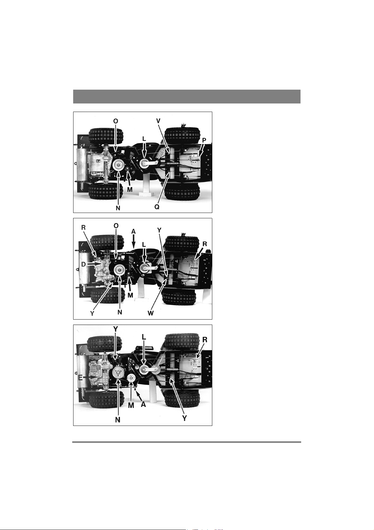
REPLACING THE V - BELTS
You can replace the v-belts while the machine is
standing on its wheels.
Remark: To illustrate how to replace v-belts the
machines are shown here from below and on there
sides (figs 24 - 26).
Always use genuine belts. They will fit properly
and last longest.
V-BELT ENGINE - POWER TAKE-OFF
The power take-off referred to here is the double
belt pulley L which is located in the middle of the
machine and is used to drive the cutter deck/accessory by means of a separate v-belt.
1. Remove the v-belt which runs from the power
take-off to the cutter deck/accessory.
2. Unscrew the tension roller M.
3. Crank off the v-belt from the lower belt groove
N on the engine belt pulley.
4. Remove the v-belt from the upper belt groove on
the power take-off.
5. Replace the v-belt and assemble in the reverse
order.
V-BELT ENGINE - TRANSMISSION
1. Remove the v-belt from between the engine and
power take-off. See above.
2a. Classic:
Keep the left-hand pedal (clutch pedal) pressed
down.
2b. President-Pro16-Pro18:
Keep the left-hand pedal (brake pedal) pressed
down.
3. Classic:
Slacken the belt guides on the transmission belt
pulley and turn them aside.
4. Unscrew the tension roller O.
5. Crank off the v-belt from the transmission belt
pulley. (Pro16-Pro18: Run the v-belt through the
fan.)
6. Remove the v-belt from the upper belt groove N
on the engine belt pulley.
7. Replace the v-belt and assemble in the reverse
order.
ADJUSTING GEAR POSITIONS
(Classic)
If the gear positions do not agree with the markings on the instrument panel the gear control cable can be adjusted at the elbow links P on the cable (fig 24).
ADJUSTING CLUTCH (Classic)
The clutch cable should be adjusted so that there is
a play of about 10 mm on th clutch pedal. The
clearance is adjusted with the cable adjusters Q on
the clutch cable (fig 24).
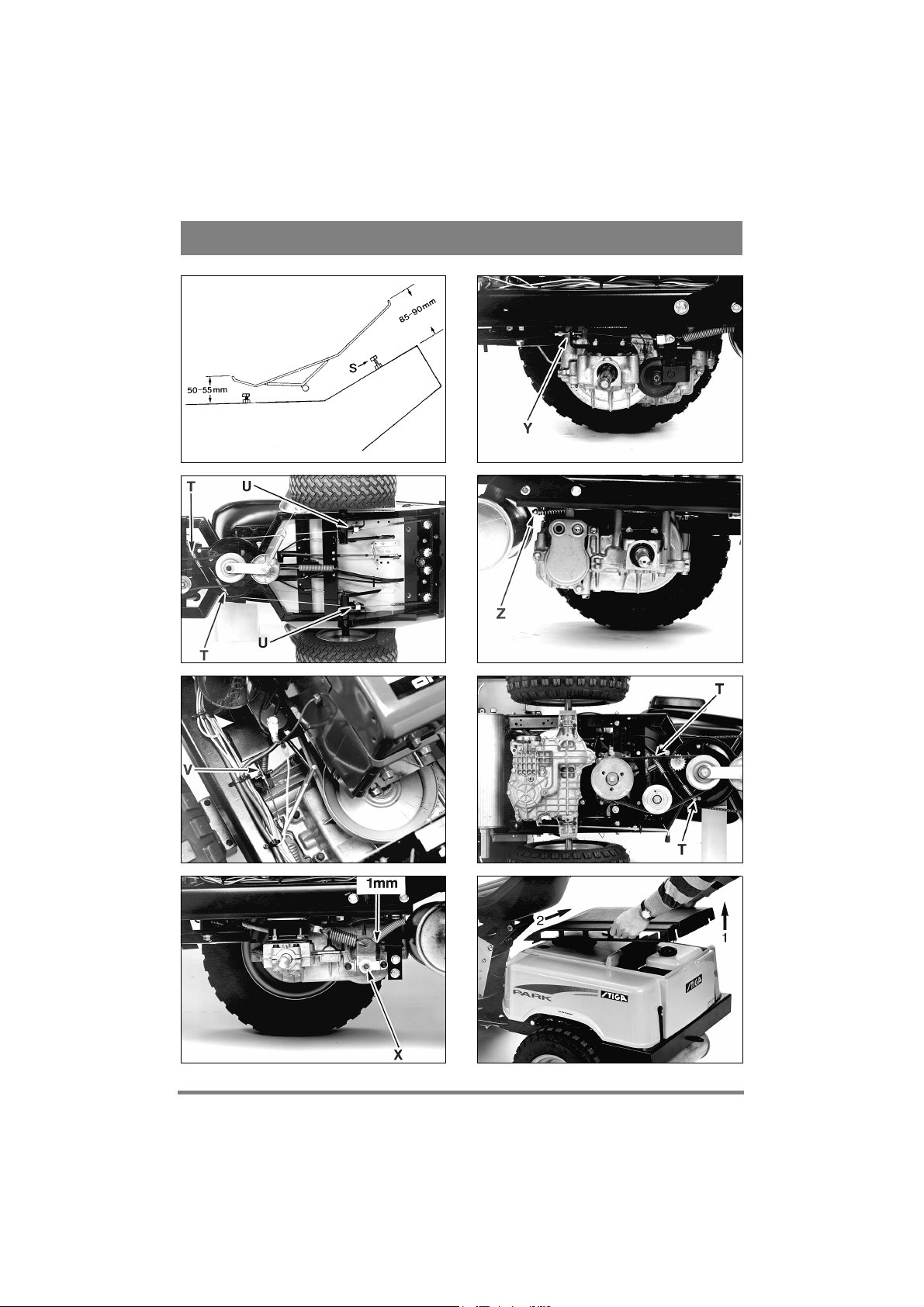
ADJUSTING THE DRIVE PEDAL
(President - Pro16 - Pro18)
When the transmission is in neutral (the machine is
stationary) the drive pedal should be adjusted in
such a way that the gap between the front part of
the pedal and the floor plate is 85 - 90 mm, and the
gap between the rear part of the pedal and the floor
plate is 50 - 55 mm (see fig 27).
You can adjust the position of the pedal in both
ends of the cable:
1. Slacken the elbow link R at the drive pedal and/
or at the transmission unit (figs 25 - 26).
2. Adjust the position of the drive pedal by screw-
ing the elbow link out or in on the cable.
3. Then screw the elbow link securely into position
again at the drive pedal/transmission unit.
PEDAL STOP
It is important that the pedal stop is adjusted correctly after the cable is replaced or adjusted. If it is
not, the transmission can be seriously damaged.
1. Screw the pedal stop S down as far as it can go
(fig 27).
2. Then press the front part of the drive pedal until
it resists (= end position of transmission).
3. Then release the front part of the drive pedal by
about 5 mm.
4. Screw the pedal stop up until it touches the low-
Page 16

ENGLISH
GB
er side.
5. Tighten the pedal stop locking nut.
The forward movement of the drive
pedal must not be restricted by the end
position of the transmission, otherwise
serious damage may arise.
6. Then adjust the pedal stop under the rear part of
the drive pedal. The backward movement of the
drive pedal should be about half the forward movement.
STEERING CABLES (Classic President)
After the machine has been in operation for a few
hours the steering cables should be adjusted.
Put the machine in the straight ahead position.
Tension the steering cables by tightening up the
nuts at T. The screws in the ends of the cables
should be held firmly during adjustment. Use an
adjustable wrench or similar for the purpose, inserting it in the key handles in the ends of the
screws (fig 28).
Adjust both cables so that the distance between the
pulley at U and the chain is the same on both sides
of the machine.
Tension the cables until they are no longer slack.
Once adjustment is complete, turn the steering
wheel as far as it will go in either direction. Check
that the chain does not come in contact with the
pulley, and that the cables do not become entangled with the steering pinions.
ADJUSTING STEERING CHAIN
(Pro16 - Pro18)
The steering chain must be adjusted after every 50
hours of use.
Put the machine in a "straight on" position.
Tension the steering chain by tightening the nuts T
(fig 33). Adjust until all play is removed.
Do not over-tighten the steering chain. This will
cause the steering to become heavy and increase
wear on the steering chain.
ADJUSTING THE BRAKE
Do not adjust the brake so hard that it 'locks' when
the brake pedal is not pressed and while the machine is in operation.
Classic:
Adjust the brake cable on the cable adjusters V so
that the brake arm is about 1 mm from the stop
when the brake pedal is in the released position
(figs 24 and 29 - 30).
Slacken the lock nut and screw in the adjusting nut
X (fig 30). Tighten the lock nut.
President:
Adjust the brake cable to allow about 10 mm play
in the brake pedal. Adjust the play by means of the
cable adjusters Y (figs 25 and 31).
After adjustment, make sure the clutch
is always activated before the brake.
If it is not, adjust the separate clutch cable W (fig
25).
Pro16-Pro18:
Adjust the combined brake/clutch cable to allow
about 10 mm play in the brake pedal. Adjust the
play by means of the cable adjusters Y (fig 26).
When adjusting, make sure the cable's
clutch function is always actived before
the brake function.
Then adjust the brake drum with the help of the adjusting nut Z (fig 32).
STIGA reserves the right to make changes in the product
without prior notice.
Page 17

GB
ENGLISH
EC - DECLARATION OF
CONFORMITY
Model: Park
Type: P401
Art. no.: 13-1258, 13-1358, 13-1458, 13-1818,
Serial no.: See machine
Manufact.: STIGA AB, P.O. Box 1006,
Product: Lawn mower with combustion engine
This product complies with the following:
- Electromagnetic Compatibility Directive 89/336/EEC
- Machine Directives 89/392/EEC, 91/386/EEC and
93/44/EEC with particular reference to Annex 1 in
the Directive concerning essential health and safety
requirements in connection with construction and
manufacture.
Place: Tranås, 1th January, 1998
Signature:
13-1442, 13-1443, 13-1446, 13-1448
S-573 28 Tranås, Sweden
Production Manager
Page 18
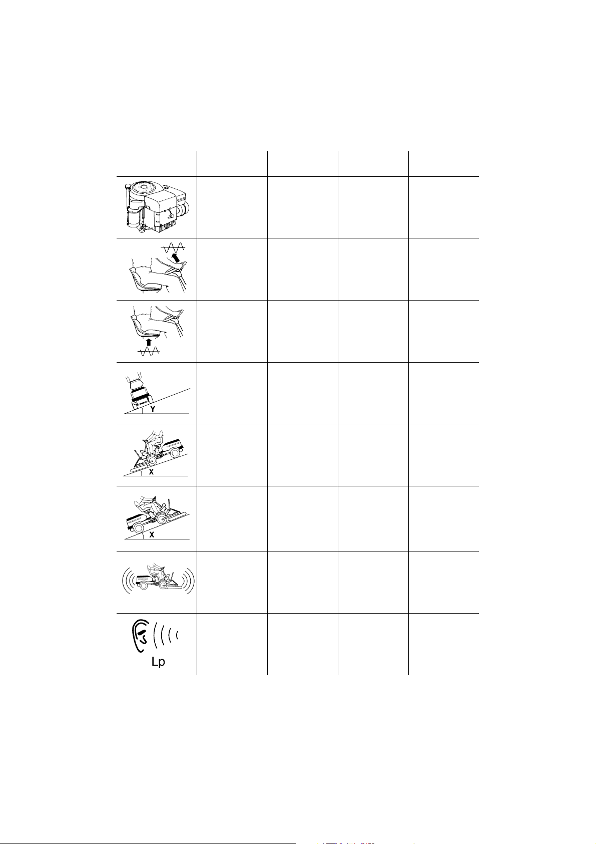
Park
Classic
Park
President
Park
Pro 16
Park
Pro 18
3400 min
9.3 kW
4.5 m/s
< 0.5 m/s
-1
2
2
3400 min
4.5 m/s
< 0.5 m/s
9.3 kW
-1
3400 min
-1
3400 min
11.8 kW
2
2
< 2.5 m/s
< 0.5 m/s
2
2
< 2.5 m/s
< 0.5 m/s
< 10° < 10° < 10° < 10°
< 10° < 10° < 10° < 10°
-1
13.2 kW
2
2
LWA
< 10° < 10° < 10° < 10°
100B: 100 dB(A)
102M: 99 dB(A)
100B: 87 dB(A)
102M: 85 dB(A)
100B: 99 dB(A)
102M: 99 dB(A)
110S: 100 dB(A)
100B: 87 dB(A)
102M: 85 dB(A)
110S: 87 dB(A)
100B: 98 dB(A)
102M: 97 dB(A)
110S: 100 dB(A)
121M: 99 dB(A)
100B: 86 dB(A)
102M: 84 dB(A)
110S: 88 dB(A)
121M: 86 dB(A)
100B: 97 dB(A)
102M: 97 dB(A)
121M: 98 dB(A)
100B: 84 dB(A)
102M: 84 dB(A)
121M: 86 dB(A)
Page 19

MOWING AHEAD
Box 1006 · SE-573 28 TRANÅS
www.stiga.com
 Loading...