

Page 1

Edition Manual Chapter Page
2005-05-04 Workshop Manual, Stiga Park 1 General instructions 1
Workshop
manual
Primo
2008
Page 2

Edition Manual Chapter Page
2008-03-18 Workshop Manual, Stiga Primo 1 General 1
1 General instructions
Contents in this chapter
General
This Workshop Manual is intended for Stiga Primo model 2008.
This Manual do not cover repair instructions for the motor. Regarding the motor, see the
motor manual.
This Manual and its specifications are valid for machines in their original design. In case of
modified or changed machine, i.e. the motor is replaced, the manual accordance is limited.
The manual is divided in the following chapters:
Chapter 1 is this chapter
Chapter 2 Chassis
Chapter 3 Steering
Chapter 4 Belts
Chapter 5 Electrical system
Chapter 5 Cutting deck
1.4 Unpacking and assembly......... 5
1.4.1 Unpacking.............................. 5
1.4.2 Battery ................................... 6
1.4.3 Assembly............................... 7
1.4.4 Final checks........................... 9
1.4.5 General tightening torque...... 10
1.5 Instructions for use .................. 10
1.6 Raising....................................... 11
1.6.1 Raising back.......................... 11
1.6.2 Raising front........................... 11
1.7 Turning upsidedown................. 12
1.7.1 Preparing............................... 12
1.7.2 Draining the petrol ................. 12
1.7.3 Seat with its plate................... 12
1.7.4 Motor hood............................. 13
1.7.5 Motor oil................................. 13
1.7.6 Petrol tank.............................. 13
1.7.7 Turning................................... 13
1.7.8 Restoring the machine on its
wheels.................................... 13
1.1 Introduction................................2
1.1.1 Responsibility declaration.......2
1.1.2 How this manual is used ........2
1.2 Safety Precautions ....................2
1.2.1 Before service or maintenance2
1.2.2 Symbols and general
warnings.................................3
1.2.3 Warm parts.............................3
1.2.4 Moving parts...........................3
1.2.5 Lifting and blocking up............3
1.2.6 Cleanliness.............................3
1.2.7 Tightening torque ...................3
1.2.8 Sharp edges...........................3
1.2.9 Replacement parts.................3
1.2.10 Inspection.............................3
1.3 Guarantee...................................4
1.3.1 Guarantee period ...................4
1.3.2 Exeptions................................4
1.3.3 Conditions for validity of the
warranties...............................4
Page 3

Edition Manual Chapter Page
2008-03-18 Workshop Manual, Stiga Primo 1 General 2
1.1 Introduction
1.1.1 Responsibility declaration
In spite of the great care we have taken there may be errors in this publication.
The author cannot be made liable for incorrect or missing information.
GGP SE reserves the right to regularly change product specifications without prior notice.
All the information in this book is based on the information available at the time of
production. Illustrations and photographs may be arranged schematically, which implies
that one picture may cover several models and therefore not correspond exactly with all
models.
1.1.2 How this manual is used
To make this manual easy to understand we have divided the machine into its main
systems and components. These parts are now the different chapters in the book.
Each chapter is divided up into sections.
There is a quick-guide on the cover of this book, which refers to the different chapters. In
each chapter there is a detailed table of contents so that you can easily and quickly find
what you are looking for.
1.2 Safety Precautions
This manual has been written primarily for trained mechanics working in a well-equipped
workshop. Nevertheless, the manual contains such detailed information that it can also be
of use to owners who wish to carry out simple service and repairs on their machine.
A basic knowledge of repairs, tools and repair instructions is, however, always a
prerequisite for first-rate results.
A qualified mechanic should always be consulted if the owner does not have sufficient
knowledge to carry out repairs.
During the warranty period all service must be carried out by an Authorised Workshop for
the warranty to be valid.
The following basic points should be observed if the machine is to function perfectly:
• Follow the service schedule.
• Be on the alert for sudden vibrations or abnormal noise to avoid major breakdowns.
• Always use Genuine Spare Parts
• Follow the descriptions in this manual carefully. Do not take any short cuts.
1.2.1 Before service or maintenance
Before service or maintenance is carried out, the mesures below shall be performed:
• Prevent the machine from rolling by always applying the parking brake.
• Prevent unintentional starting of the engine by removing the ignition key.
• All service and all maintenance must be carried out on a stationary machine with the
engine switched off.
Page 4

Edition Manual Chapter Page
2008-03-18 Workshop Manual, Stiga Primo 1 General 3
1.2.2 Symbols and general
warnings
Warning!
This symbol indicates a risk of
personal injury or damage if the
instructions are not followed.
Note!
This text indicates a risk of damage to
the material or risk of unnecessarily
complicated work if the instructions
are not followed.
1.2.3 Warm parts
Please observe that engine and exhaust
system picks up a lot of heat during use.
T o avoid injuries, allow the machine to cool
before any kind of repairs are made to or
near parts of the engine or exhaust
system.
1.2.4 Moving parts
The machines are all equipped with v-belt
transmissions. Always stop the engine and
remove the starter key before inspections
or repairs are carried out.
Always use extreme caution when testing
systems with moving parts to avoid
injuries.
Always use Genuine Spare Parts during
service work.
1.2.5 Lifting and blocking up
Before work under the machine, always
make sure that lifting devices and jackstands are approved for the weight.
Work safe!
1.2.6 Cleanliness
Clean the machine before starting repairs.
Dirt that penetrates into sensitive
components can seriously influence the
service life of the machine.
1.2.7 Tightening torque
Unless otherwise stated the tightening
torque in the tables in the section
Technical specifications must be used for
the different sizes of screws. This does not
refer to self-tapping screws, which are
mainly used for the assembly of body
parts.
1.2.8 Sharp edges
Watch out for sharp edges, especially
when working with the mower deck. The
blades can be very sharp. Always wear
gloves when working with the blades.
1.2.9 Replacement parts
Always use Genuine Spare Parts during
service work.
1.2.10 Inspection
Each part dismantled in conjunction with
service work must be inspected.
Examine for: wear, cracks, out of
roundness, straightness, dents,
discolouring, abnormal noise and
jamming.
Page 5

Edition Manual Chapter Page
2008-03-18 Workshop Manual, Stiga Primo 1 General 4
1.3 Guarantee
1.3.1 Guarantee period
For consumer use: two years from date of
purchase.
1.3.2 Exeptions
The extended warranty does not cover
damage due to the following:
• Neglect by users to acquaint themselves
with accompanying documentation.
• Carelessness.
• Incorrect and non-permitted use or
assembly.
• The use of non-genuine spare parts.
• The use of accessories not supplied or
approved by the manufacturer.
Neither does the warranty cover:
• Wearing components such as blades,
belts, wheels,battery and cables.
• Normal wear.
• Engine and transmission. These are cov-
ered by the respective manufacturer’s
warranties, with separate terms and conditions.
The purchaser is covered by the national
laws of each country. The rights to which
the purchaser is entitled with the support of
these laws are not restricted by this
warranty.
1.3.3 Conditions for validity of the
warranties
The fully completed warranty card must be
sent to Stiga´s subsidiary or distributor.
Page 6
Edition Manual Chapter Page
2008-03-18 Workshop Manual, Stiga Primo 1 General 5
1.4 Unpacking and assembly
Every Stiga machine has undergone an
extensive control programme before delivery.
The machines are delivered as completely
assembled as possible.
Thanks to this the assembly on delivery is rapid
and easy.
The correct and careful assembly of the
machine on delivery is a simple way of ensuring
satisfied customers!
Note!
The machine shall remain placed on the
pallet during the unpacking and
assembly.
1.4.1 Unpacking
Open up the crate and release the part as
follows:
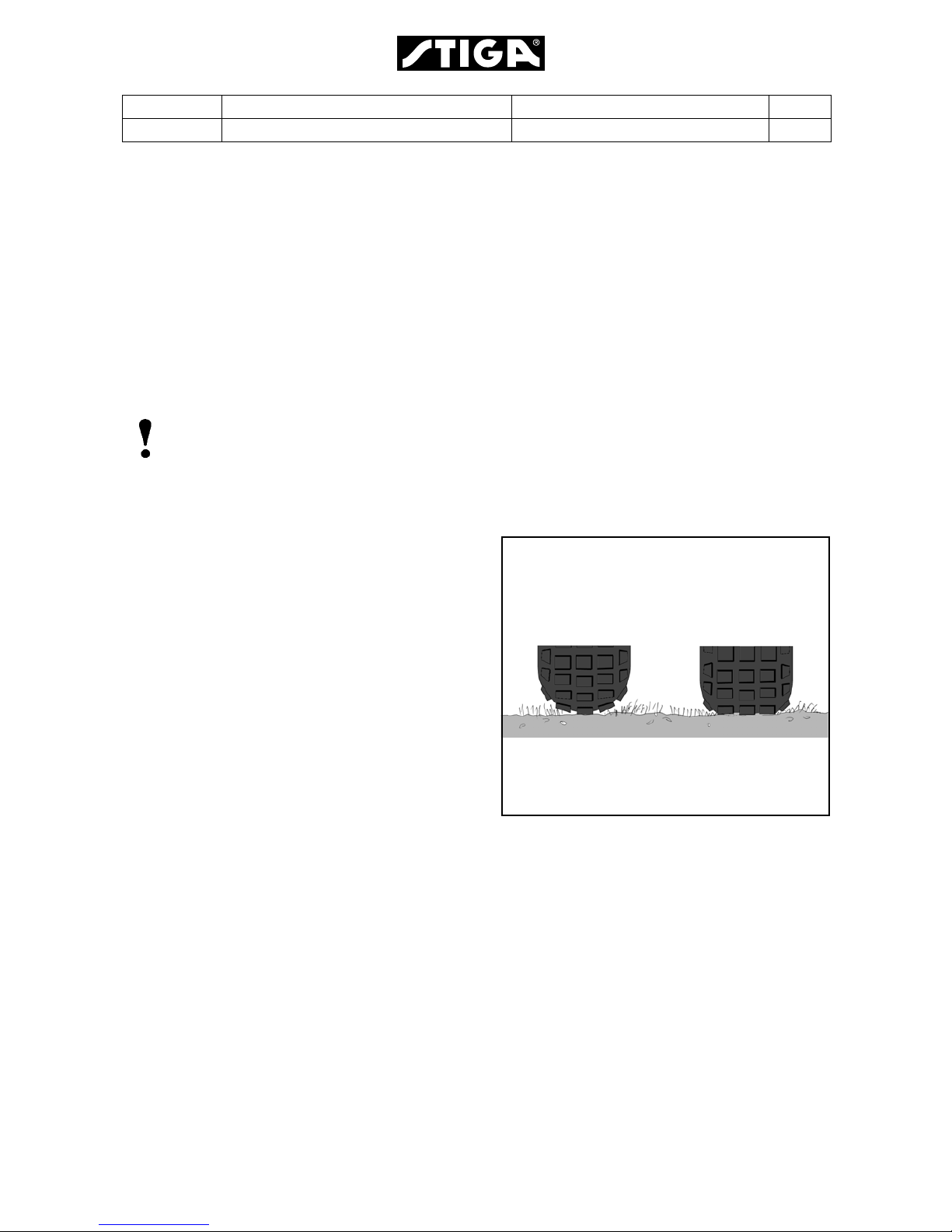
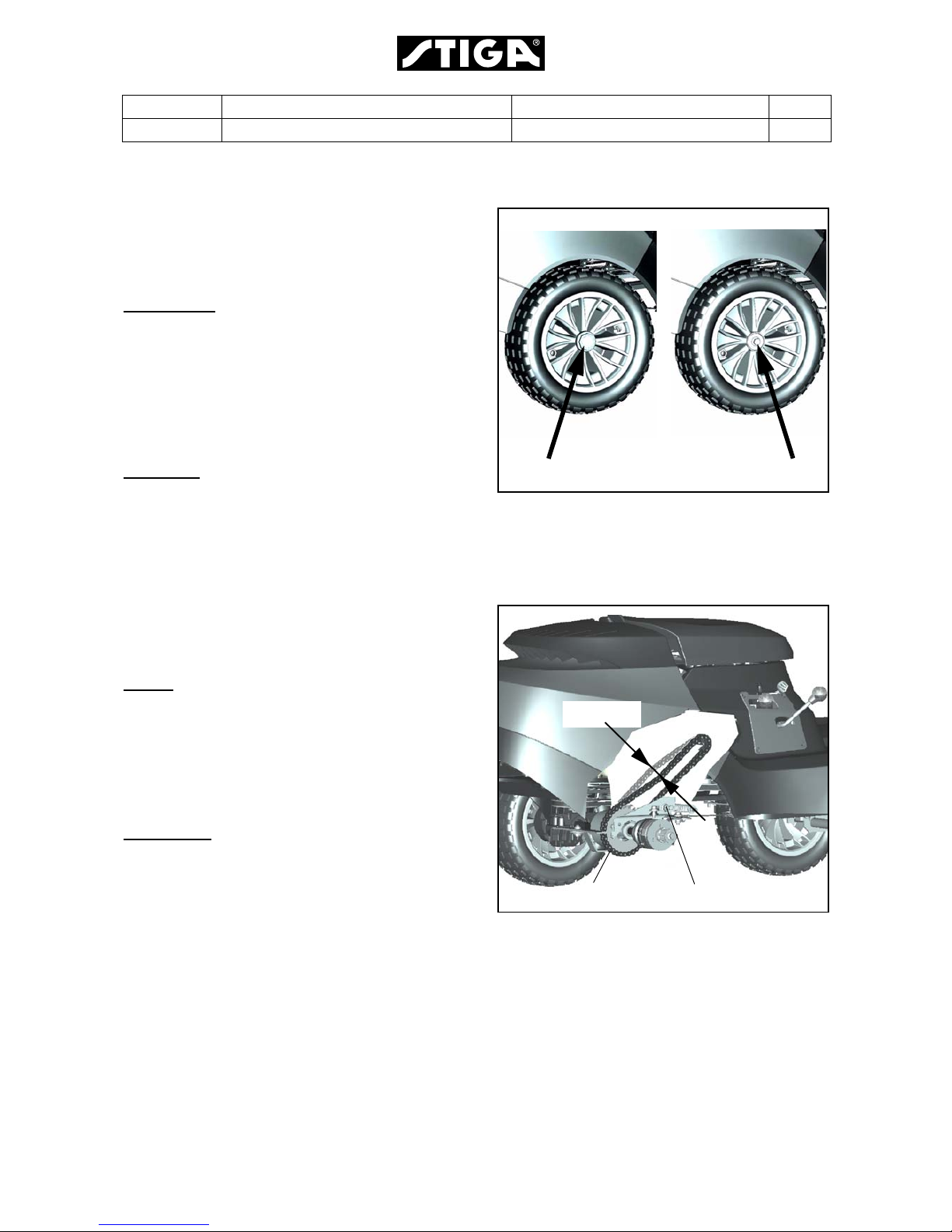
1. Check the air pressure in the tyres. The
pressure is designated on the floor mat.
The air pressure in the tyres is of critical
importance for the performance and
handling of the machine. The correct air
pressure for mowing is:
Front: 1,2 bar (17 psi)
Rear: 1,2 bar (17 psi)
Too high pressure in the tyres leads to that
the machine drives poor due to:
• A small surface in contact to the ground.
• Hard tyre = less flexibility = self cleaning characteristic deteriorate.
2. Remove the following parts from the
package and put them on the floor.
• The steering wheel.
• The backrest.
• The plastic bag, containing owners manuals,
and assembly screws.
Too high pressure Correct pressure
Page 7
Edition Manual Chapter Page
2008-03-18 Workshop Manual, Stiga Primo 1 General 6
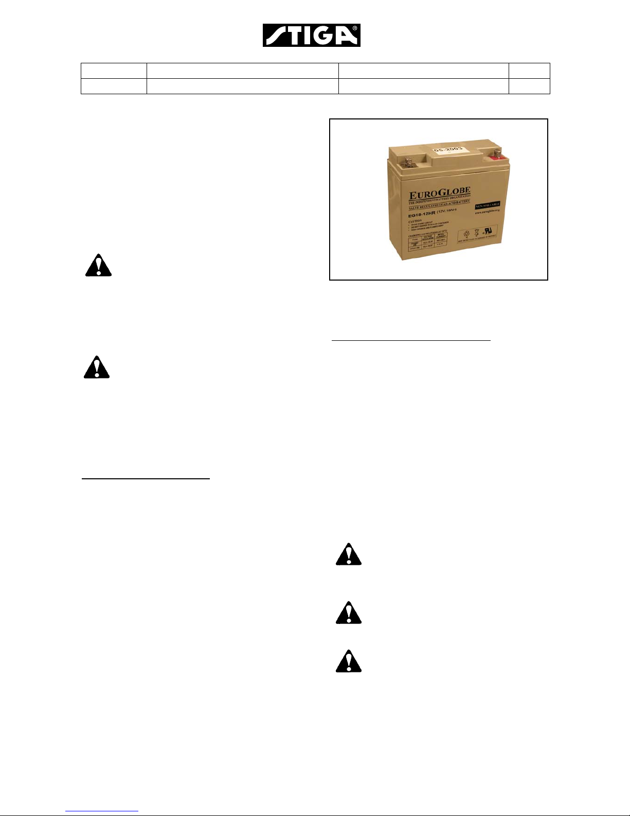
1.4.2 Battery
The battery is a valve regulated type.
Valve regulated battery
This battery needs limited maintenance. It has
no electrolyte levels or plugs.
Warning!
Do not wear rings, metallic bracelet,
chain round the neck or similar metal
objects when working with the
battery. It can cause short-circuit,
burns and fire.
Warning!
The battery must be fully charged
before being used for the first time.
The battery must always be stored
fully charged. If the battery is stored
while discharged, serious damage will
occur.
Charging with the engine
The battery can be charged using the engine’s
generator as follows:
1. Install the battery in the machine as shown
below.
2. Place the machine outdoors or install an
extraction device for the exhaust fumes.
3. Start the engine according to the
instructions in the user guide.
4. Allow the engine to run continuously for 45
minutes.
5. Stop the engine. The battery is now fully
charged.
Charging using battery charger
When charging using a battery charger, a
battery charger with constant voltage must
be used.
The battery can be damaged if a standard
type battery charger is used.
Installation of battery
Connect first the red cable to plus (+) and
then the black cable to minus (-).
If the cables are disconnected/
connected in the wrong order ,
there is a risk of a short-circuit
and damage to the battery.
If the cables are interchanged,
the generator and the battery
will be damaged.
The engine must never be driven
with the battery disconnected.
There is a risk of serious
damage to the generator and the
electrical system.
Page 8
Edition Manual Chapter Page
2008-03-18 Workshop Manual, Stiga Primo 1 General 7
1.4.3 Assembly
The assembly procedure shall take place in a
clean, well illuminated and dry place.
Assemble the machine as follows:
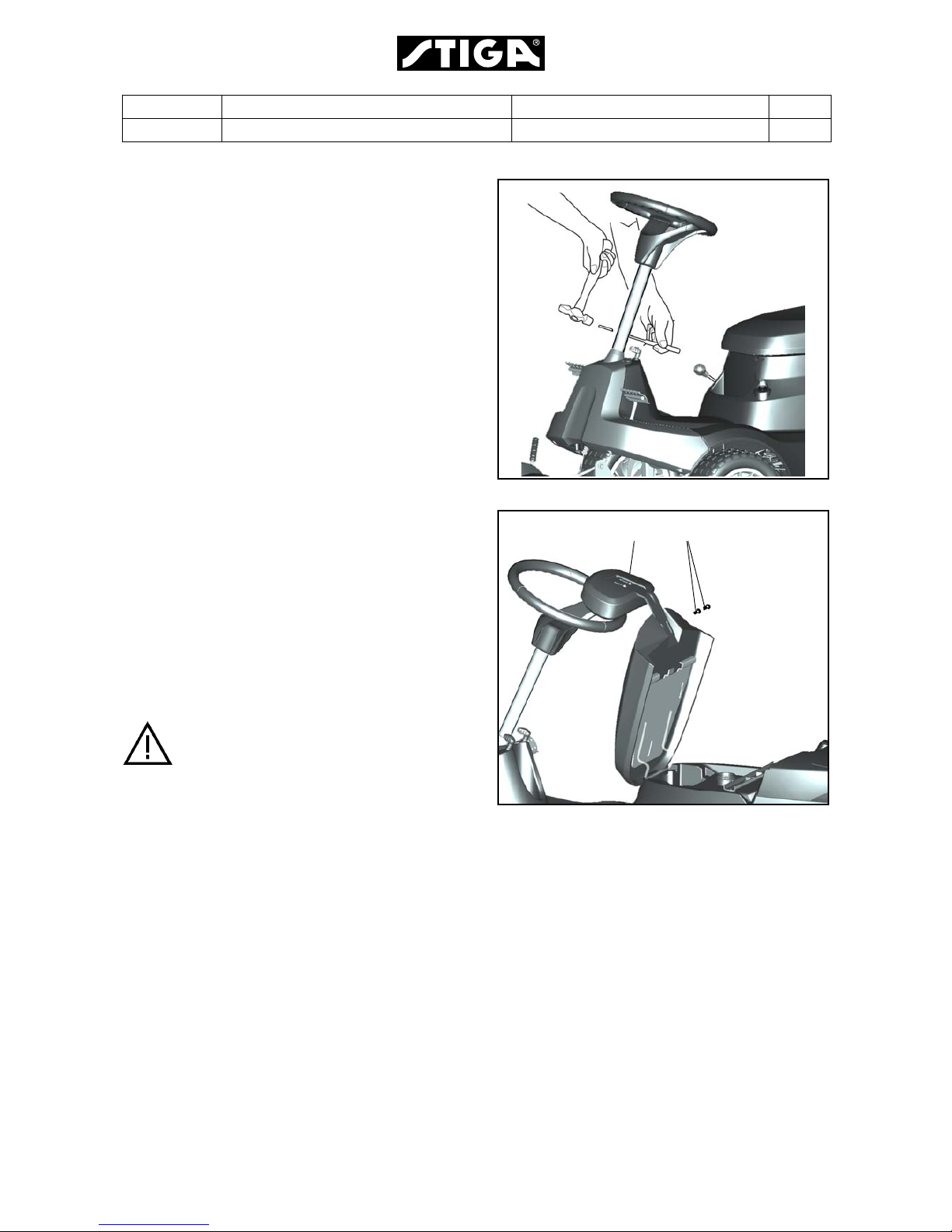
Steering wheel
Install the steering wheel as follows:
1. Install the steering column jacket on the
steering column using a drift or similar so
that the holes in the steering column jacket
and steering column align with each other.
2. Tap in the supplied tension pin from the
other side using a hammer.
Backrest
Install the backrest as follows:
1. Fold the seat up towards the steering wheel.
2. Install the backrest with the screws (O)
without tightening.
3. Set the backrest to the desired position.
4. Tighten the screws. Tightening torque: 2024 Nm.
If the screws are tightened more than
24 Nm, the seat will be damaged.
N O
Page 9
Edition Manual Chapter Page
2008-03-18 Workshop Manual, Stiga Primo 1 General 8
Seat
Adjust the seat backwards/forwards to a
comfortable driving position.
The seat can be folded and adjusted front-rear.
To adjust the seat, slacken of f the three screws
(P), set the seat to the desired position and
tighten the screws.
Tightening torque: 20-24 Nm.
If the screws are tightened more than
24 Nm, the seat will be damaged.
The seat is equipped with a safety switch that is
connected to the machine’s safety system. This
means that certain dangerous activities are not
possible when there is nobody sitting on the
seat.
Backrest
The backrest can be adjusted laterally and
vertically . T o adjust the backrest, slacken off the
screws (O), set the backrest to the desired
position and tighten the screws. Tightening
torque: 20-24 Nm.
If the screws are tightened more than
24 Nm, the seat will be damaged.
Battery
Fold the seat up and install the battery leads.
See also“1.4.2”.
Engine oil
Check the oil level in the engine and top up if
necessary.
A
P
ON
Page 10

Edition Manual Chapter Page
2008-03-18 Workshop Manual, Stiga Primo 1 General 9
1.4.4 Final checks
The final check consists of test driving and
safety check as described below.
Test driving
Warning!
Do not drive without the mover deck
attached. Risk for turning over.
Drive the machine for a few minutes. Test all
the functions. Pay special attention to the
safety functions. The mower deck must be
fitted before test driving the machine.
Listen to abnormal noise or rattle during the test
driving.
Safety check
Check the safety functions. It is often
appropriate to do this check in conjunction with
test driving. The following items shall be
checked at all machines:
• No leakage on fuel lines and connections.
• No mechanical damages to the electrical
cables. All insulation intact.
• The muffler shall be undamaged and its
screws tightened. No exhaust leakage in connections.
The electrical check items are listed in the
tables below.
Test Status Action Result
1 PTO activated.
No gear activated.
Turn the key and make a
start attempt.
Motor shall not
start.
2 PTO not activated.
A gear is activated.
Turn the key and make a
start attempt.
Motor shall not
start.
3 Motor running.
PTO activated.
Operator rises from the
seat.
Motor shall
stop.
4 Motor running.
A gear activated.
Operator rises from the
seat.
Motor shall
stop.
Page 11

Edition Manual Chapter Page
2008-03-18 Workshop Manual, Stiga Primo 1 General 10
1.4.5 General tightening torque
Unless otherwise stated, the following
tightening torque are applicable for screws and
nuts on the machine:
1.5 Instructions for use
Some procedures, e.g. changing motor oil,
motor filter etc., are refered to the instruction for
use, delivered with the machine.
The instruction of use is written in 16 languages
and divided in two parts. The first part always
contains the languages SV, FI, DA, NO, DE,
EN, FR and N.
Tightening torques
Thread Torque
M5 5 Nm
M6 9 Nm
M8 22 Nm
M10 45 Nm
Page 12
Edition Manual Chapter Page
2008-03-18 Workshop Manual, Stiga Primo 1 General 11
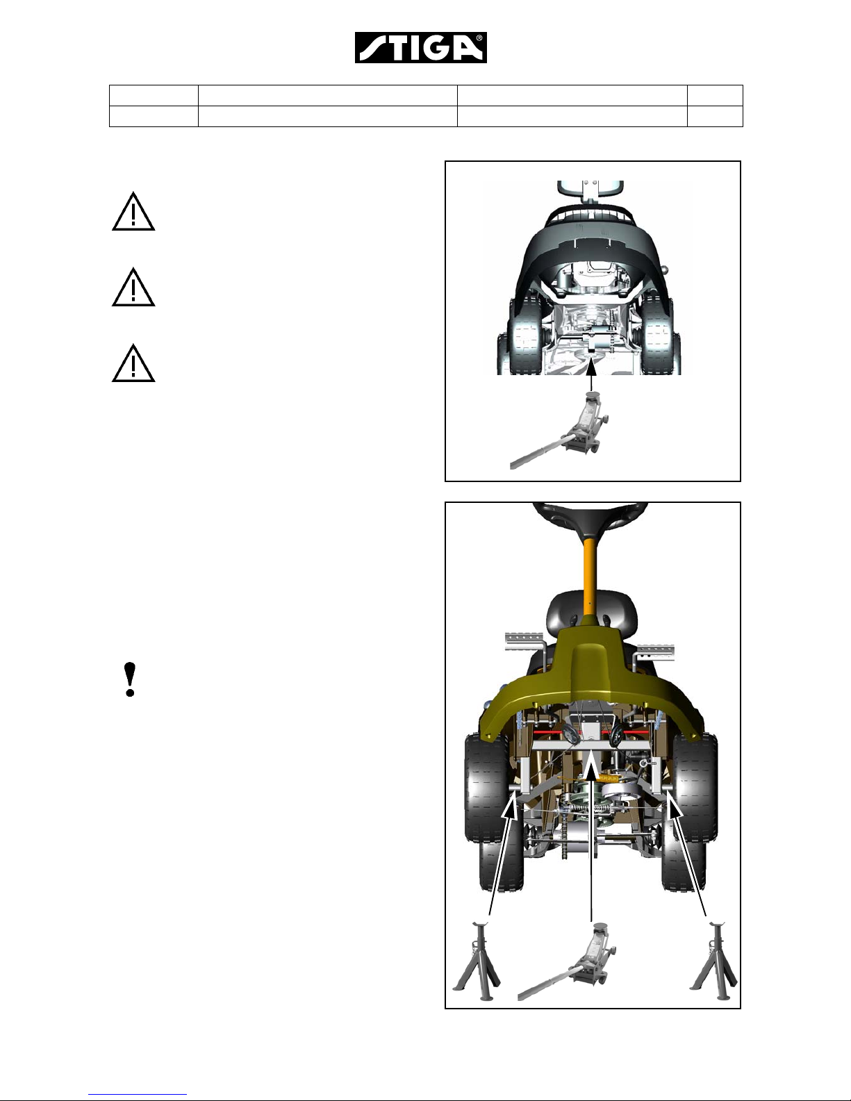
1.6 Raising
Jacks must only be placed in the
designated area. Placing the jack in
other locations will damage the
machine.
The machine must only be raised on
hard, stable and horizontal surfaces.
Otherwise there is a risk of the
machine dropping.
The machine must never be loaded
with further weight when it is raised.
Nobody must sit on the machine when
it is raised.
1.6.1 Raising back
For certain maintenance work, the rear part of
the machine must be raised slightly so that the
required rear wheel can be removed. Raise the
machine as follows:
1. Position the machine on a hard, stable and
horizontal surface.
2. Raise the machine using a jack, see the fig.
1.6.2 Raising front
Note!
To raise the machine at the front, the
cutting deck must be removed.
Raise the machine at the front as follows:
1. Place the machine on a flat, solid and
horisontal ground.
2. Disassemble the cutting deck. See chapter 6.
3. Raise the machine with help of a jack and
apply the yokes according to the figure.
For location of jack and yokes, see the figure.
1
1
2
2
Page 13
Edition Manual Chapter Page
2008-03-18 Workshop Manual, Stiga Primo 1 General 12
1.7 Turning upsidedown
Some service measures are facilitated by
turning the machine upsidedown on a work
bench.
1.7.1 Preparing
Before the machine is turned, the following
items must be disassembled:
• Cutting deck, see chapter 6
• Draining the petrol
• Seat with its plate
• Motor hood
• Motor oil
• Petrol tank
1.7.2 Draining the petrol
Petrol is highly inflammable. Always
store fuel in containers that are made
especially for this purpose.
Only handle petrol outdoors, and
never smoke during petrol handling.
Never handle petrol together with a
warm or running engine.
1. Place the machine outdoors.
2. Drain the petrol tank by loosening the hose
at the fuel cock. Close the hose and insert it
in a suitable container until the tank is
empty.
3. Start the engine and let it run until it the
carburettor is empty and the engine stops.
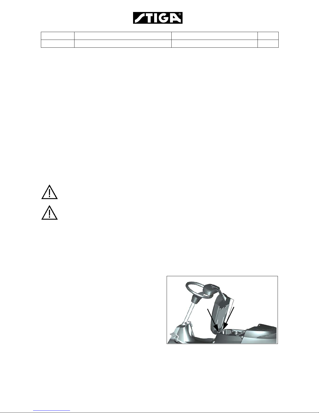
1.7.3 Seat with its plate
1. Fold up the seat and remove the screws
(A).
2. Lift up and remove the seat with the seat
plate.
A
A
Page 14

Edition Manual Chapter Page
2008-03-18 Workshop Manual, Stiga Primo 1 General 13
1.7.4 Motor hood
1. Open the motor hood.
2. Person 1 holds the hood on one side and
person 2 holds the other side and removes
the screws (B).
3. Lift carefully up the hood and place it on a
soft surface.
1.7.5 Motor oil
Drain the motor oil. See the owners manual.
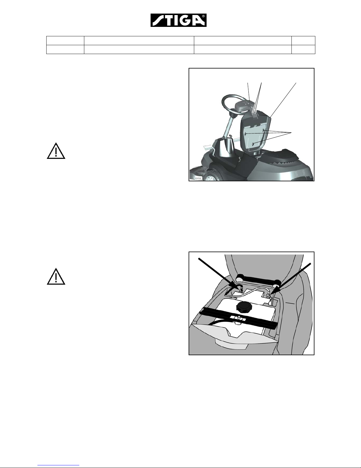
1.7.6 Petrol tank
Loosen the screws holding the crossbar (C)
and remove the crossbar.
Loosen the screw (D) holding the tank and
battery cage and remove the tank and battery
cage with battery.
1.7.7 Turning
Prepare a work bench to place the machine on.
Two persons lif t the machine, one person at the
rear and one at the front.
Lift and turn the machine 180°. Place it carefully
on the work bench.
1.7.8 Restoring the machine on its
wheels
To restore the machine on its wheels, perform
the instructions above in the opposite order.
BB
CD
Page 15
Edition Manual Chapter Page
2008-03-18 Workshop Manual, Stiga Primo 2 Chassis and Body 1
2 Chassis and body
Contents in this chapter
General
To facilita te the driving, handling of work equipment and to make it comfortable for the
driver, the machines are equipped with a various number of aid equipments.
This chapter gives a brief description of the equipments and describes their repair and
replacements.
This chapter also contains information about how to repair the plastic chassis including
material and threads.
2.3 Lubrication chassis .................... 4
2.3.1 Drive chain............................... 4
2.3.2 Steering cable.......................... 4
2.3.3 Tensioning arms, movable joints5
2.3.4 Throttle cable........................... 5
2.3.5 Bearings................................... 5
2.1 Repair of the chassis...................2
2.1.1 Repair of cracks........................2
2.1.2 Repair of threads......................2
2.2 Wheel............................................3
2.2.1 Adjusting the drive chain (U) ....3
Page 16
Edition Manual Chapter Page
2008-03-18 Workshop Manual, Stiga Primo 2 Chassis and Body 2
2.1 Repair of the chassis
There are two types of chassis repair:
• Repair of cracks i.e. after interferences etc.
• Repair of threads.
2.1.1 Repair of cracks
Consult the dealer for detailed information.
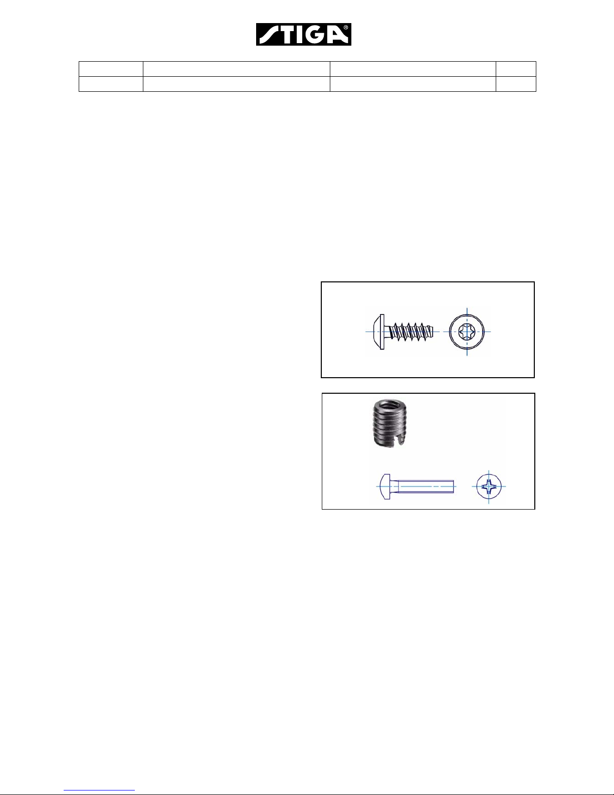
2.1.2 Repair of threads
A number of screws are threaded direct into the
chassis. The screws used are shown in the
figure to the right.
Threads for those screws can be repaired as
follows:
1. Order a repair kit for threads. See the spare
parts list.
2. Drill out the defect thread in the chassis with
a 7 mm drill.
3. Screw the thread adapter (A) from the repair
kit into the hole with the recess first. The
recess is intendet to cut the thread in the
plastic material.
The thread adapter is screwed in with a
screw in its internal thread.
4. Use a csrew M5x25 (B) from the repair kit
and fit the actual item.
A
B
Page 17
Edition Manual Chapter Page
2008-03-18 Workshop Manual, Stiga Primo 2 Chassis and Body 3
2.2 Wheel
For certain maintenance work, it is necessary
to remove a rear wheel.
Dismantling:
1. Raise the machine according to chapter 1.
2. Remove the cover disc (A).
3. Use a 17 mm wrench and remove the screw
(B) with disc.
4. Pull the wheel from the axle.
Assembly:
1. Slide the wheel onto the axle.
2. Install the screw (B) with disc.
3. Tighten the screw to 40-45 Nm.
2.2.1 Adjusting the drive chain (U)
Check/adjust the belt tension each season as
follows:
Check:
1. Raise the machine and remove the righthand rear wheel. See 6.4.
2. The chain (15:U) must have 5-10 mm of
play.
Any required adjustment, see blow.
Adjustment
:
Adjust the play by moving the tensioner wheel
as follows:
1. Slacken off the nut (15:T) and set the
tensioner wheel to the desired position.
2. Tighten the nut and check the play. Adjust
again if required.
3. Tighten the nut to 40-45 Nm when
adjustment has been completed.
AB
5-10 mm
T
U
Page 18

Edition Manual Chapter Page
2008-03-18 Workshop Manual, Stiga Primo 2 Chassis and Body 4
2.3 Adjustments
2.4 Brake - Clutch
General
Pedal has the following functions:
•Clutch
• Service brake
• Parking brake
The pedal has three positions:
1. Pedal released – forward drive engaged.
The machine will move if a gear is engaged.
Service brake not activated.
2. Pedal depressed halfway – forward drive
disengaged, gear shifting can be performed.
Service brake not activated.
3. Pedal fully depressed – forward drive
disengaged. Service brake fully activated.
Also see “Parking brake” below.
4. Pedal fully depressed and locked – Parking
brake.
Adjustment
The adjustment is performed in 2 steps:
Step 1
The pedal shall have a play of 10-20 mm at the
top.
Adjust this play by inserting the cotter pin in a
suitable hole in the brake rod.
Note!
Check that the pedal return spring (A) is
in place. If not, the play cannot be felt.
10-20 mm
A
Page 19

Edition Manual Chapter Page
2008-03-18 Workshop Manual, Stiga Primo 2 Chassis and Body 5
Step 2
Adjust the brake to act according to the
description under “General” at the previous
page.
The adjustment is performed at the center nut
at the gearbox brake lever.
• Turn the nut CW to increase the braking
effect.
• Turn CCW to decrease the braking effect
Page 20

Edition Manual Chapter Page
2008-03-18 Workshop Manual, Stiga Primo 2 Chassis and Body 6
2.5 Lubrication chassis
All lubrication points according to the table
below must be lubricated after every 25
operating hours as well as after each clean.
2.5.1 Drive chain
Lubricate the drive chain (U) using chain spray
as follows. Use universal type chain spray.
1. Trestle up the machine’s right-hand rear
wheel so that it can rotate freely.
2. Brush the chain clean using a wire brush.
3. Rotate the rear wheel by hand and at the
same time spray the chain so that it is fully
lubricated.
4. Lower the machine.
2.5.2 Steering cable
Lubricate the steering cable using chain spray
as below. Use universal type chain spray.
1. Brush the chain clean using a wire brush.
2. Turn the steering wheel and at the same
time spray the cable so that it is fully
lubricated.
Item Chapter / Section
Drive chain 2.3.1
Steering cable 2.3.2
Tensioning arms
and moving joints
2.3.3
Throttle cable 2.3.4
U
Page 21

Edition Manual Chapter Page
2008-03-18 Workshop Manual, Stiga Primo 2 Chassis and Body 7
2.5.3 Tensioning arms, movable joints
Lubricate the bearing points using an oil can at
the same time as activating the respective
control.
Preferably carried out by two people.
Activate the controls:
• Steering
• Clutch, brake
• Raise the cutting deck
• Engaging the cutting deck.
• Setting the cutting height
2.5.4 Throttle cable
Lubricate the cable ends using an oil can at the
same time as activating the respective control.
2.5.5 Bearings
Shafts and attachments pivoted in the plastic
chassie shall be lubricated with universal
grease.
Page 22

Edition Manual Chapter Page
2008-03-18 Workshop Manual, Stiga Primo 3 Steering 1
3 Steering
Contents in this chapter
General
The machine is equipped with a mechanical steering system, working with a wire.
This chapter contains a brief description of the function and describes repair , replacements
and adjustments of stressed parts of the steering system.
3.1 Steering wire..............................2
3.1.1 Description .............................2
3.1.2 Dismantling.............................2
3.1.3 Assembly................................3
3.1.4 Steering pulleys......................5
Page 23

Edition Manual Chapter Page
2008-03-18 Workshop Manual, Stiga Primo 3 Steering 2
3.1 Steering wire
3.1.1 Description
The steering power from the steering wheel is
transmitted to the rear wheels by a wire as
follows:
• The roller (A) is turned by the steering wheel
and mowes the wire (B).
• The wire is pulling the lever (C), which affects
the wheels by the rods (D)
3.1.2 Dismantling
Note!
Observe how the wire is located above/
under rods, arms etc. This observation is
helpful at the installation of the new wire.
1. Remove the four steering pulleys (E). Use a
15 mm and a 17 mm wrench.
2. Remove the nut (F), holding the wire end.
Use a 13 mm wrench and a pliers to hold the
wire end.
3. Remove the spring
4. Unwind the wire from the steering roller and
unhook it from the rear attachment.
5. Remove the wire from the machine.
A
B
C
D
E E
E
E
F
Page 24

Edition Manual Chapter Page
2008-03-18 Workshop Manual, Stiga Primo 3 Steering 3
3.1.3 Assembly
1. Hook on the wire to the rear steering lever.
2. Mount the 2 pulleys (E) with the wire at the
right side of the machine.
Note!
Locate the wire as observed during the
dismantling.
Check that the wire not interface with
frame parts, rods, levers etc.
Lubricate the pulleys and mount them
according to the figure.
See “3.1.4 Steering pulleys”.
3. Turn the steering wheel until the wire rivet
hole in the steering roller is facing forwards.
4. Wind up the wire on the steering roller.
Keep the right part of the wire stretched by
blocking or holding the rear wheels.
St art winding at position (A), wind 1,25 turns
and push in the rivet (B) into the hole in the
steering roller.
5. Continue to wind up the wire another 1,25
turns.
EE
AB
Page 25

Edition Manual Chapter Page
2008-03-18 Workshop Manual, Stiga Primo 3 Steering 4
6. Fit the threaded wire to the rear steering
lever.
Note!
Locate the wire as observed during the
dismantling.
Check that the wire not interface with
frame parts, rods, levers etc.
Mount the following parts:
• Spring (G)
• Nut (F). To facilitate the mounting of the
remaining steering pulleys, screw on the
nut a few turns only.
6. Mount the two pulleys at the left part of the
machine together with the wire.
See “3.1.4 Steering pulleys”.
7.Tighten the nut (F) and compress the spring
until its length is 108 mm. Hold the wire with
a pliers.
8. Turn the wheels fully out in both directions.
Check that there is no abnormal noise or
abnormal resistance.
FG
E E
108 mm
Page 26

Edition Manual Chapter Page
2008-03-18 Workshop Manual, Stiga Primo 3 Steering 5
3.1.4 Steering pulleys
Every singel steering pulley consists of the
following parts:
A.Screw
B.Washer
C.Bushing
D.Steering pulley
E.Part of the frame
F.Nut
Assembly instructions:
• Check the wear, specially of the steering pulley, and replace defective parts.
• Apply a thin layer of machine oil to the bushing (C).
A
B
C
D
E
F
Page 27

Edition Manual Chapter Page
2008-03-18 Workshop Manual, Stiga Primo 4 Belts 1
4 Belts
Contents in this chapter
General
All mechanical power, delivered by the motor, is conducted to the different power
consuments by a belt system. The maximum tension of each belt is regulated by a spring
loaded belt tensioner.
This chapter gives a brief description of the belt system and describes replacements of
belts and adjustments of their tensions.
This chapter is valid for the actual machines where the actual system occur.
4.1 Description.................................2
4.2 Belt theory..................................3
4.2.1 Why it is so important to use
original belts from the
retail dealer?...........................3
4.3 Replacement of belts................5
4.3.1 Disassembly of belt C ............5
4.3.2 Inspection and measures.......6
4.3.3 Assembly of belt C.................7
4.3.4 Adjustmen of PTO brake........7
Page 28

Edition Manual Chapter Page
2008-03-18 Workshop Manual, Stiga Primo 4 Belts 2
4.1 Description
Belt A
Belt A belongs to the work equipment and is
connected to the machine pulley (double)
(3). The belt is tensioned by the tension
pulley (2) which is mounted on a spring
loaded lever.
Belt B
Belt B is intended to deliver the motor power
to the pulley (double) (3), where it can be
picked up by the work equipment.
Belt B also performs the mechanic PTO
clutch function together with the pulley (5).
Engagement/disengagement of the
mechanic PTO is performed by moving the
pulley (5) to stretch/slacken the belt.
Belt C
Belt C is intended to transmitt the motor
power to the transmission, where it is geared
to a suitable ratio for the drive shaft. The belt
is tensioned by the tension pulley (6) which
together with the belt performs the clutch
function.
The tensioning force is disengaged from the
belt when the parking brake is activated.
Belts:
A. Work equipment belt (belongs to the work
equipment).
B. Work equipment belt.
C.Transmission belt.
Pulleys:
1. Pulley at the work equipment.
2. Tension pulley.
3. Pulley (double).
4. Pulley at the transmission.
5. Tension pulley with PTO clutch function.
6. Tension pulley with clutch function.
7. Drive pulley at the motor shaft.
8. Drive pulley at the motor shaft.
A
B
C
1
2
3
4
5
7
8
6
Page 29

Edition Manual Chapter Page
2008-03-18 Workshop Manual, Stiga Primo 4 Belts 3
4.2 Belt theory
4.2.1 Why it is so important to use original belts from the retail dealer?
The table below shows the demands on normal commercial grade belts compared to
demands on original spare parts belts from the retail dealer. The later are designed and
manufactured in close connection between the subcontractor and the rider manufacturer.
The table is intended to display the importance to use the original belts.
Case Commercial
grade belts
Original spare
par ts belts
Remarks
Fitness to pulleys. The belt shall rest
with its angled
sides against the
pulleys. There
must be a space
between belt and
pulley bottom.
The belt shall rest
with its angled
sides against the
pulleys. There must
be a space
between belt and
pulley bottom.
Same demands.
Original belts
guarantee that the belt
fits against the pulleys.
Acceleration. The belt follows
the motor rpm in a
continuous
acceleration up to
full speed.
Some belts shall
engage to the
pulleys with the
motor running in full
speed, which gives
an excessive
generation of heat.
Common belts are
made of natural rubber,
which can resist
temperatures up to 70°
only.
Original belts are made
of chloroprene rubber,
which can resist
temperatures up to 90°
Length Manufactured in
standard lengths
in steps..
Manufactured in
preedefined lengths
to fit between the
pulleys..
The distance between
the pulleys is fix. The
belt tensioner gives the
original belt an optimal
tension.
.
Page 30

Edition Manual Chapter Page
2008-03-18 Workshop Manual, Stiga Primo 4 Belts 4
Case Commercial
grade belts
Original spare
par ts belts
Remarks
Floating pulley at
the implement.
Designed to
transmit power
between aligned,
paralell and fixed
pulleys.
The original PTO
belt is designed to
operate, even if the
pulleys are moving
up and down and
are tilting at the
same time
The implement follows
the ground which
involves that its pulley
is constant moving.
To resist the excessive
operating conditions,
the original belts are
made of fibre
reinforced rubber.
Bending in two
directions
Designed to bend
around pulleys in
one direction only
Most of the belts at
the machine have
tension rollers,
actuating from the
outside of the belt.
This means the the
belt has to bend
both inwards and
outwards during the
operation.
All original belts which
operate with tension
rollers actuating from
the outside have
reinforcements. The
reinforcement is
special designed for
the actual case.
Noise Manufactured
without any
special respect to
the actual case.
The original belts
are carefully
selected to give the
lowest noise
increment to the
machine during
operation.
Depending on the
function of the belt, any
of the following belt
types are itemised:
• Wrapped
• Non-friction
• Raw-edge
Page 31

Edition Manual Chapter Page
2008-03-18 Workshop Manual, Stiga Primo 4 Belts 5
4.3 Replacement of belts
This section describes the belt changing of belt
C. For changing other belts, see actual parts of
the belt C description.
4.3.1 Disassembly of belt C
The belt C is the uppermost belt and is intended
to conduct the engine power to the gearbox.
The belt is controled by a lever for the clutch
function.
Dismantle the belt as follows:
1. Raise the machine by one of the alternatives
below:
• With a highjack and yokes. See section 1.
• With a lifting table.
2. Set the cutting deck (if mounted) to max
cutting heighth.
3. If the cutting deck is mounted; Pull out the
pulley (H) and take down the belt to unload
the belt tension.
4. If the cutting deck is mounted; Remove the
belt A.
A
C
B
H
A
Page 32

Edition Manual Chapter Page
2008-03-18 Workshop Manual, Stiga Primo 4 Belts 6
5. Unhook all springs and note where the
respective spring is attached.
6. Remove the split pin and unhook the rod (R)
at the front.
7. Remove the pulley (5). Use a 15 mm and a
17 mm wrench.
8. T ake of f the belt (B) first from pulley (8), then
thread it around the pulley 3 and finally,
remove it.
9. Remove the pulley (6). Use a 15 mm and a
17 mm wrench.
10.Remove the belt (C) from the pulleys (4) and
(7).
4.3.2 Inspection and measures
1. Check and lubricate all links.
• The links shall move easily and not have
any major play.
• Lubricate all pivot linkages with machine
oil.
2. Check the belts.
• The belt shall rest with its angled sides
against the pulleys. There must be a
space between belt and pulley bottom.
• The belt shall be intact. No loose parts or
cracks.
3. Check all ball bearings with respect to the
following:
• No radial play.
• The sealing shall be intact.
• No abnormal noise when rotating. Shall
rotate evenly without stop tendency.
Replace all defective parts with genuine
spare parts.
3B 5 8R
67C4
Page 33

Edition Manual Chapter Page
2008-03-18 Workshop Manual, Stiga Primo 4 Belts 7
4.3.3 Assembly of belt C
Assemble all part in the reverse order.
After the assembly, adjust the PTO brake. See
below.
4.3.4 Adjustmen of PTO brake
Warning!
It is important that the movement of
the tensioning arm is always
stopped by the brake pad, and not
by the engagement rod. If the rod
stops the movement, the braking capacity can be completely lost when
the parts become worn.
1. Remove the rod link and press the brake
shoe hard against the pulley.
Hold the threaded stud above the lever
close to the hole. In this position, 1/4 of the
threaded stud diameter shall overlap the
hole diameter.
2. Adjust the nipple towards + to increase the
brake function.
Adjust the nipple towards - to decrease the
brake function.
.
1/4 Dia.
Page 34

Edition Manual Chapter Page
2008-03-18 Workshop Manual, Stiga Primo 4 Belts 8
3. When 1/4 of the diameters overlap, fit the
nipple in the hole and assemble the nut as
follows:
A. Screw on and tighten the nut moder-
ately.
B. Loosen the nut 1/2 turn.
The nipple shall be movable in the hole.
Warning!
If the nipple is tight in its hole, un-
normal stress will occour to the mechanical parts.
4. When the adjustment is complete, the following items shall be fulfilled:
• Engage the PTO and check that the
brake pad no longer brakes the pulley . If
the brake pad still brakes the belt pulley ,
adjust again.
• Disengage the PTO and check that the
brake works.
If everything is correctly adjusted the
brake should be applied just enough for
the double PTO belt pulley to be turned
round by hand only with extreme force.
Page 35

Edition Manual Chapter Page
2008-03-17 Workshop Manual, Stiga Primo 5 Electrical System 1
5 Electrical System
Contents in this chapter
General
The electrical system has two main duties, to maintain the machine safety and to make the
different functions easy to handle.
The main part of this chapter consists of trouble shooting of the electrical system to isolate
faults and to give information about corrective measures. The electrical system is also
described. There are also given instructions about general repair and replacement
procedures.
5.2.6 The motor can be started with a
gear activated.............................6
5.2.7 The motor does not stop when the
operator leaves the seat and the
mover deck is activated..............7
5.3 Repair and replacements..............8
5.3.1 Connections ...............................8
5.3.2 Circuit diagram...........................9
5.1 Description.....................................2
5.2 Trouble Shooting...........................3
5.2.1 The starter does not rotate......... 4
5.2.2 The starter rotate, but the motor
does not start..............................5
5.2.3 The battery runs repeatedly
empty..........................................5
5.2.4 The motor does not stop............6
5.2.5 The motor can be started with the
mover deck activated .................6
Page 36

Edition Manual Chapter Page
2008-03-17 Workshop Manual, Stiga Primo 5 Electrical System 2
5.1 Description
The electrical components are connected with cables, integrated in a complete insulated
harness. Thus the cables are protected against wear, contaminations and other stresses.
The cables are connected to the actual components with tab or screw connectors and in
some cases with multi-contact connectors.
The electrical system contains several safety circuits. Therefore actual levers and pedals
are provided with micro switches. The micro switches are shown in the figure below. The
signals from the micro switches are used to interlock the actual circuit in case of a forbidden
manoeuvre attempt. Some manual switches and relays have also built in interlocks, related
to the safety system.
To achieve a complete understanding of the electrical system, read also the actual wiring
diagram.
All current consumption circuits except the start circuit are protected by a fuse.
Microswitch at the
Microswitch under the seat
Microswitch at the
gearbox
PTO lever
View from the inside
Page 37

Edition Manual Chapter Page
2008-03-17 Workshop Manual, Stiga Primo 5 Electrical System 3
5.2 Trouble Shooting
Warning!
Do not wear rings, metallic bracelet, chain round the neck or similar metal
objects when working with the electrical system. It can cause short-circuit,
burns and fire.
This section describes the trouble shooting procedures in absence of an electrical function.
It also describes the correction measures in each actual case. When following the trouble
shooting schedules, it is provided that the following states are fulfilled:
• All fuses are checked and, if necessary replaced.
• The battery shall be charged.
• The requirements for the actual measure shall be fulfilled. E.g. if it is advised to perform a
start attempt, the gear shall be in neutral and the power take off shall be in disengaged
position.
When following the trouble shooting shedules, it is in normal cases assumed that
conductors and connectors to conductors are OK. However, in some cases, after a long
period of use or in case of mechanical damages.
Page 38

Edition Manual Chapter Page
2008-03-17 Workshop Manual, Stiga Primo 5 Electrical System 4
5.2.1 The starter does not rotate
Page 39

Edition Manual Chapter Page
2008-03-17 Workshop Manual, Stiga Primo 5 Electrical System 5
5.2.2 The starter rotate, but the motor does not start
5.2.3 The battery runs repeatedly empty
Page 40

Edition Manual Chapter Page
2008-03-17 Workshop Manual, Stiga Primo 5 Electrical System 6
5.2.4 The motor does not stop
5.2.5 The motor can be started with the mover deck activated
5.2.6 The motor can be started with a gear activated
Page 41

Edition Manual Chapter Page
2008-03-17 Workshop Manual, Stiga Primo 5 Electrical System 7
5.2.7 The motor does not stop when the operator leaves the seat and the
mover deck is activated
Page 42

Edition Manual Chapter Page
2008-03-17 Workshop Manual, Stiga Primo 5 Electrical System 8
5.3 Repair and replace-
ments
Warning
Do not wear rings, metallic bracelet,
chain round the neck or similar metal objects when working with the
electrical system. It can cause
short-circuit, burns and fire.
5.3.1 Connections
The machine is equipped with three kinds of
connectors:
• Fixed connectors in plastic holders.
• Tab connectors
• Screw connectors
All connectors shall be kept free from
contamination, corrosion and damp.
Fixed connectors in plastic holders
To remove the connectors from the plastic
holder, put a small screwdriver behind the
connector, hold the cable and pull out the
connector.
See the figure.
Tab connectors
To restore tab connectors if bad crimp
forces occur, e.g. after a long time of use,
the connector can be pinched by a pliers.
See the figure.
Page 43

Edition Manual Chapter Page
2008-03-17 Workshop Manual, Stiga Primo 5 Electrical System 9
Screw connectors
When cables shall be connected into screw
connectors, the cable shall be stripped off 5
mm only . No metallic conductor is allowed to
be exposed outside the terminal.
Warning!
Exposed conductors can cause
short-circuit and fire.
5.3.2 Circuit diagram
Page 44

Edition Manual Product Page
2008-03-18 Workshop Manual, S tiga Primo 6 Mower Decks 1
6 Mower Deck
Contents in this chapter
6.4 Disassembly and assembly....... 5
6.4.1 Disassembly ............................5
6.4.2 Assembly.................................6
6.4.3 Replacing blades.....................7
6.4.4 Synchronising blades...............8
6.4.5 Safety.......................................8
6.4.6 Replacing driving belt ..............9
6.4.7 Replacing timing belt ...............9
6.4.8 Replacements of pulleys and bear-
ing boxes..................................11
6.1 General .........................................2
6.1.1 General tightening torque.........2
6.2 Cutting theory..............................3
6.2.1 Cutting height...........................3
6.3 Original blades.............................4
6.3.1 Why it is so important to use
original blades and blade tips
from the retail dealer?...............4
6. Mover Deck
Page 45

Edition Manual Product Page
2008-03-18 Workshop Manual, S tiga Primo 6 Mower Decks 2
6.1 General
The decks are equipped with two synchronised rotating blades. The tracks of adjacent
blades are overlapping each other, which means that the synchronization is vit al. All shafts/
pulleys are pivoted in sealed and permanent lubricated bearing boxes.
All decks are provided with a coupling to simplify the cleaning and inspection procedure.
The decks are also provided with an manual adjusting device for the cutting height.
All decks are tested prior to delivery.
This chapter describes repair, replacements and adjustments of stressed parts of the
mower decks.
6.1.1 General tightening torque
Unless otherwise stated, the following tightening torque are applicable for screws and nuts
on the machine:
Tightening torques:
Thread Torque
M5 5 Nm
M6 9 Nm
M8 22 Nm
M10 45 Nm
Page 46

Edition Manual Product Page
2008-03-18 Workshop Manual, S tiga Primo 6 Mower Decks 3
6.1 Cutting theory
6.1.1 Cutting height
The best cutting results are achieved when the
when the top third of the grass is cut off.
I.e. 2/3 of the length of the grass remains.
If the grass is long and has to be cut
significantly, cut twice using different cutting
heights.
Do not use the lowest cutting heights if the lawn
surface is uneven. This would entail a risk of the
blades being damaged against the surface and
the lawn’s top layer of soil being removed.
1/3
Page 47

Edition Manual Product Page
2008-03-18 Workshop Manual, S tiga Primo 6 Mower Decks 4
6.2 Original blades
6.2.1 Why it is so important to use original blades and blade tip s from the
retail dealer?
The table below shows the demands on original blades and blade tips, delivered from the
retail dealer.
The table is intended to display the importance to use theoriginal blades and blade tips.
Demand Remarks
No splitting of blade tips. Using steel balls, the manufacturer simulates what can
happen if you drive over foreign objects on the lawn. The
sharpening of the blades may be destroyed, but no parts are
allowed to loosen or fly away.
No splitting of blades. The impact test is the toughes durability test a lawn mower can
be subject to. An iron pipe is placed right into the blades during
operation.
The blade can be deformed but it may not under any
circumstances, come off or split.
This test verifies that blades and other parts fulfil the high
safety requirements.
Optimal balance.
Minimum of noise.
Minimum of vibrations.
Blades and blade tips from the retail dealer have exactly the
same weight.
Blades and blade tips from the retail dealer are optimal
balanced.
This guarantee a minimum of vibration and noise which gives
a maximal durability of the machine.
It also guarantee that the machine corresponds to the
specification according to noise and vibrations.
Optimal cutting result. Blades and blade tips from the retail dealer are optimized in
the application. I.e. the blades are adapted to the shape och
the cover and the number of revolutions to give the best cutting
result.
.
.
.
Page 48

Edition Manual Product Page
2008-03-18 Workshop Manual, S tiga Primo 6 Mower Decks 5
6.3 Disassembly and assem-
bly
Certain maintenance works are simplified if the
cutting deck is removed from the machine.
6.3.1 Disassembly
Disassemble the cutting deck as follows:
1. Set the highest cutting height.
2. Pull out the tensioning roller (H) and move the
belt down (J) at the side of the tensioning roller
to release the belt tension.
3. Work off the belt from the pulley.
4. Lift the deck and hook off the lifting wire (K).
5. Disassemble the locking screws (L) at both
sides.
H
J
K
L x2
Page 49

Edition Manual Product Page
2008-03-18 Workshop Manual, S tiga Primo 6 Mower Decks 6
6. Hook off the deck from the front axes and take
it out in the forward direction. See the figure.
6.3.2 Assembly
Install the cutting deck as follows:
1. Hook the deck over the front axles.
2 Install the locking screws (L) on both sides.
3. Set the maximum cutting height.
4. Raise the deck and hook on the lift cable (K).
L x2
K
Page 50

Edition Manual Product Page
2008-03-18 Workshop Manual, S tiga Primo 6 Mower Decks 7
5. Install the belt (J) onto the pulley.
6. Pull out the belt idler (H) and place it on the
outside of the belt so that the belt tensions.
6.3.3 Replacing blades
Warning!
The blades are sharp. Always wear
gloves when working with the blades
to avoid injury.
Warning!
When replacing, both blades on the
same blade bar must be replaced to
avoid imbalance.
Check that the blades are always sharp. This
produces the best cutting results. The blades
should be replaced once a year.
Always check the blades after a collision. If the
blade system has been damaged, defective
parts should be replaced.
Always use genuine spare parts. Nongenuine spare part s can entail a risk of
injury, even if they fit the machine.
The blades are replaceable. When replacing,
both blades on the same blade bar must be
replaced to avoid imbalance.
Attention!
Note the following when reassembling:
• The blades and blade bar must be installed
as in the figure.
• The blades can be turned 1/3 of a turn in their
mountings. Select positions so that the blades
are offset 90° from each other. See below.
Tightening torque:
• Screws (P) - 45 Nm
• Shear bolts (Q) - 9.8 Nm
In the event of a collision, the shear bolts (Q)
can break and the blades bend back. If this has
happened, install genuine shear bolts and
tighten as above.
H
J
P
PQ
Q
45 Nm
Page 51

Edition Manual Product Page
2008-03-18 Workshop Manual, S tiga Primo 6 Mower Decks 8
6.3.4 Synchronising blades
The deck has synchronised blades.
If one of the blades has struck a solid object
(e.g. a stone), the synchronisation may be
altered. This entails a risk of the blades
colliding with each other.
Correctly synchronised blades must be offset
90° from each other. See the figure.
Always check synchronisation after a collision.
If the blades are not synchronised, one or more
of the following faults may have occurred in the
cutting deck:
The positive drive belt has slipped on the gear
wheels.
T orque limiting between gear wheels and blade
shaft has deployed. The arrows must be
opposite each other for an intact deck. When
torque limiting has deployed, the arrows are
not opposite each other.
The blade member is incorrectly installed on
the blade shaft. Can be installed in three
different positions. See (R).
6.3.5 Safety
To reduce the risk of accidental injury in the
event of a collision and to protect important
parts in the cutting deck, a force limiter is
integrated as follows.
• Shear bolts between blades and blade bar.
• Torque limiting between gear wheels and
blade shaft.
• Possibility of positive drive belt slipping on
the plastic gear wheels.
R
Page 52

Edition Manual Product Page
2008-03-18 Workshop Manual, S tiga Primo 6 Mower Decks 9
6.3.6 Replacing driving belt
To replace the drive belt, it is not necessary to
disassemble the deck from the machine.
Replace the driv belt as follows:
1. Remove the deck cover by unscrewing the 3
fastening screws. See the figure.
The fourth screw shall not be removed.
2. Remove the belt guide (A) by unscrewing its
two screws.
3. Loosen the belt from the machine. See previous sections.
4. Fit the new belt and reassemble in the
reverse order. See also previous sections.
6.3.7 Replacing timing belt
To replace the timing belt, disassemble the
deck from the machine.
Replace the timing belt as follows:
1. Disassemble the deck from the machine. See
previous sections.
2. Remove the deck cover by unscrewing the 3
fastening screws. See the figure above.
3. Remove the belt guide (A) by unscrewing its
two screws. See the figure above.
4. Remove the belt pulley from the left shaft by
unscrewing its screw.
A
Page 53

Edition Manual Product Page
2008-03-18 Workshop Manual, S tiga Primo 6 Mower Decks 10
5. Slacken the belt by loosen the four bearing
box screws a few turns.
6. Work off the timing belt from the pulleys and
fit the new one.
Observe the blades when fitting the new belt.
Correctly synchronised blades must be offset
90° from each other. See the figure.
7. Pretension the timing belt by forcing the loose
bearing box outwards and lock it in this position by tightening the four screws.
Page 54

Edition Manual Product Page
2008-03-18 Workshop Manual, S tiga Primo 6 Mower Decks 11
8. Check the belt tension.
When pulling out the belt 10 mm, the force
required shall be 30-40 N. See the figure.
9. Loosen the four screws and adjust again if
necessary.
10.Assemble all parts in the reverse order.
6.3.8 Replacements of pulleys and
bearing boxes
Disassembly
1. Disassembly the drive belt and timing belt as
described above.
2. Disassembly the blades as described above.
3. Unscrew the pulley screw at the left shaft and
remove the spacer.
4. Pull up the plastic timing belt pulleys.
Use an extractor if necessary.
5. Disassemble the eight screws and take out
the bearing boxes.
10 mm 30-40 N
Page 55

Edition Manual Product Page
2008-03-18 Workshop Manual, S tiga Primo 6 Mower Decks 12
Checks
When all parts are disassembled, check the
following items.
All defective parts shall be replaced
Item Check instruction
Bearing
noise
Rotate the shafts in the bearing
boxes and listen for abnormal
noise and feel if any uneven
resistance exists.
If any abnormal noise is heard or
if any uneven resistance exists
shall the bearing box be replaced.
Bearing
play
Force the shafts radially. No radial
play shell exist
Bearing
sealings
Check visually the bearing
sealings. All sealings shall be
intact.
Belts Bend the belts in all directions. No
cracks shall be visible.
Blades The blades shall be sharp. No
cracks are allowed.
Casing The casings shall be intact and
not show up errors any cracks.
Pulleys Check that the arrows coincide at
the timing belt pulleys. See
previous in this chapter.
Painting When the surfaces are completely
dry and clean, touch up the
paintwork. Use durable paint
intended for metal outdoors.
Page 56

Edition Manual Product Page
2008-03-18 Workshop Manual, S tiga Primo 6 Mower Decks 13
Assembly
All parts shall be assembled in the reverse
order.
• Note the following during the assembly:
• Lubricate all links.
• The blades shall be orrectly synchronised.
Fit the parts according to the figure.
 Loading...