

Stiga Park 2WD, Park Compact, Park CH 4WD, Park CH 2WD, Park Pro 4WD Workshop Manual

WORKSHOP MANUAL
PARK
2008 - 201ˀ

TABLE OF CONTENTS
1 - General instructions
2 - Chassis and body
3 - Steering
4 - Hydraulic system
5 - Belts
6 - Control Wires
7 - Electrical System
All brands, names, logos and trademarks mentioned belong to their respective owners.
© by STIGA - No use of the illustrations or duplication, reproduction or translation, even partial, of the texts in this
document may be made without explicit authorisation.
WORKSHOP MANUAL
PARK
1 General instructions
Contents in this chapter
Chapter
1 - General instructions
EDITION
2018
Page
1
1.1 Introduction ...................................... 2
1.1.1 Responsibility declaration .............. 2
1.1.2 How this manual is used ................ 2
1.1.3 Abbreviations ................................. 2
1.2 Safety Precautions ........................... 2
1.2.1 Symbols and warnings .................. 3
1.2.2 Warm parts .................................... 3
1.2.3 Moving parts .................................. 3
1.2.4 Lifting and blocking up ................... 3
1.2.5 Cleanliness .................................... 3
1.2.6 Tightening torque ........................... 3
1.2.7 Sharp edges .................................. 3
1.2.8 Replacement parts ........................ 3
1.2.9 Inspection ...................................... 3
1.3 Unpacking and assembly ................ 4
1.3.1 Unpacking ..................................... 4
1.3.2 Battery ........................................... 5
1.3.3 Final checks .................................. 6
1.4 Service .............................................. 7
1.4.1 Service times ................................. 7
1.4.2 First Service .................................. 8
1.4.3 Intermediate Service ..................... 8
1.4.4 Basic Service ................................ 9
1.4.5 Description of service points ....... 10
1.5 Transmission .................................. 14
1.5.1 Transmission oil and filter change
interval .................................................. 14
1.6 Technical specifications ................14
1.6.1 General tightening torque ............. 14
1.7 Instructions for use ........................ 14
General
This Workshop Manual covers all Park – Park Pro models from 2008. The Park 120-220
have a separate workshop manual. The Park Pro models from 2015 with steering cylinder
have a separate workshop manual.
This Manual do not cover repair instructions for the engines. Regarding engines, contact
the respective representative in the actual country.
This Manual and its specifications are valid for machines in their original design. In case of
modified or changed machine, i.e. the engine is replaced, the manual accordance is limited.
The manual is divided in the following chapters:
Chapter 1 is this chapter
Chapter 2 Chassis
Chapter 3 Steering
Chapter 4 Hydraulic system
Chapter 5 Belts
Chapter 6 Control Wires
Chapter 7 Electrical system

1.1
WORKSHOP MANUAL
PARK
Introduction
Chapter
1 - General instructions
EDITION
2018
Page
2
1.1.1
In spite of the great care we have taken there may be errors in this publication.
The author cannot be made liable for incorrect or missing information.
STIGA reserves the right to regularly change product specifications without prior notice.
All the information in this book is based on the information available at the time of
production. Illustrations and photographs may be arranged schematically, which implies
that one picture may cover several models and therefore not correspond exactly with all
models.
1.1.2
To make this manual easy to understand we have divided the machine into its main
systems and components. These parts are now the different chapters in the book.
Each chapter is divided up into sections.
There is a quick-guide on the cover of this book, which refers to the different chapters. In
each chapter there is a detailed table of contents so that you can easily and quickly find
what you are looking for.
Always check that you are reading the right chapter for your particular machine before
starting the repair work.
1.1.3
Responsibility declaration
How this manual is used
Abbreviations
The following abbreviations are used in this manual:
HST Hydrostatic Transmission PTO Power Take Off
1.2
Safety Precautions
This manual has been written primarily for trained mechanics working in a well-equipped
workshop.
A basic knowledge of repairs, tools and repair instructions is, however, always a
prerequisite for first-rate results.
A qualified mechanic should always be consulted if the owner does not have sufficient
knowledge to carry out repairs.
During the warranty period all service must be carried out by an Authorised Workshop for
the warranty to be valid.
The following basic points should be observed if the machine is to function perfectly:
•
Follow the service schedule.
•
Be on the alert for sudden vibrations or abnormal noise to avoid major breakdowns.
•
Always use Genuine Spare Parts
•
Follow the descriptions in this manual carefully. Do not take any short cuts.

WORKSHOP MANUAL
PARK
1 - General instructions
Chapter
EDITION
2018
Page
3
1.2.1
Symbols and general warnings
Warning!
This symbol indicates a risk of
personal injury or damage if the
instructions are not followed.
Note!
This text indicates a risk of damage to
the material or risk of unnecessarily
complicated work if the instructions
are not followed.
1.2.2
Please observe that engine and exhaust
system picks up a lot of heat during use.
This applies above all to the silencer of
machines equipped with catalytic
converter.
To avoid injuries, allow the machine to cool
before any kind of repairs are made to or
near parts of the engine or exhaust
system.
1.2.3
The machines are all equipped with v-belt
transmissions. Always stop the engine and
remove the starter key before inspections
or repairs are carried out.
Always use extreme caution when testing
systems with moving parts to avoid
injuries.
Always use Genuine Spare Parts during
service work.
1.2.4
Warm parts
Moving parts
Lifting and blocking up
1.2.5
Clean the machine before starting repairs.
Dirt that penetrates into sensitive
components can seriously influence the
service life of the machine.
1.2.6
Unless otherwise stated the tightening
torque in the tables in the section
Technical specifications must be used for
the different sizes of screws. This does not
refer to self-tapping screws, which are
mainly used for the assembly of body
parts.
1.2.7
Watch out for sharp edges, especially
when working with the mower deck. The
blades can be very sharp. Always wear
gloves when working with the blades.
1.2.8
Always use Genuine Spare Parts during
service work.
1.2.9
Each part dismantled in conjunction with
service work must be inspected.
Examine for: wear, cracks, out of
roundness, straightness, dents,
discolouring, abnormal noise and
jamming.
Cleanliness
Tightening torque
Sharp edges
Replacement parts
Inspection
Before work under the machine, always
make sure that lifting devices and jackstands are approved for the weight.
Work safe!
WORKSHOP MANUAL
PARK
1 - General instructions
1.3 Unpacking and assembly
Every STIGA Park has undergone an extensive
control programme before delivery. The
machines are delivered as completely
assembled as possible.
Thanks to this the assembly on delivery is rapid
and easy.
The correct and careful assembly of the
machine on delivery is a simple way of ensuring
satisfied customers!
Note!
The machine shall remain placed on the
pallet during the unpacking and
assembly.
1.3.1 Unpacking
Chapter
EDITION
2018
Page
4
Open up the crate and release the part as
follows:
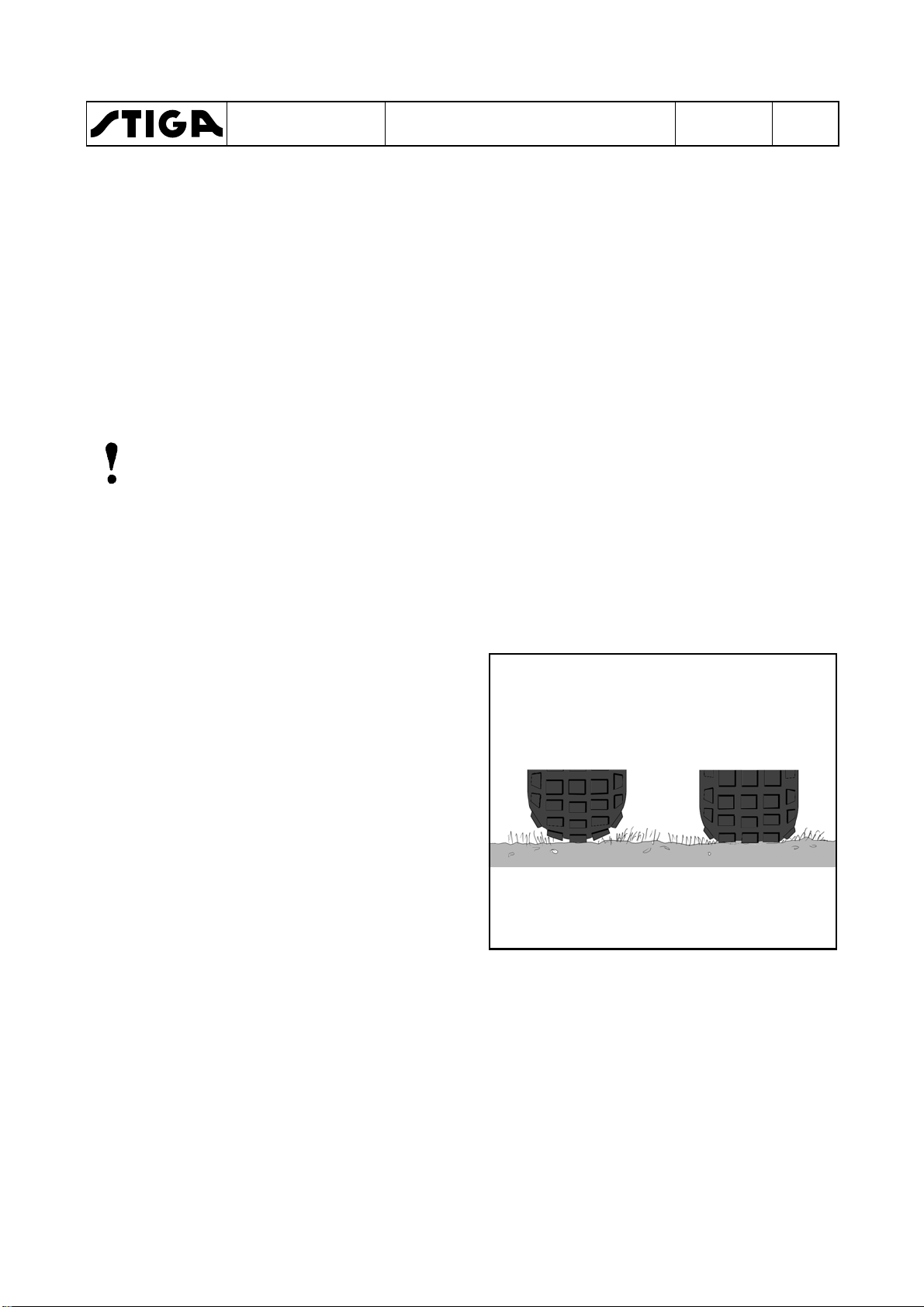
1. Check the air pressure in the tyres. The
pressure is designated on the floor mat.
The air pressure in the tyres is of critical
importance for the performance and
handling of the machine. The correct air
pressure for mowing is 0.6 bar (9 psi) in the
front tyres, and 0.4 bar (6 psi) in the rear
tyres.
When using heavy accessories, e.g. snow
thrower, it may be necessary to increase the
pressure somewhat. However, the
maximum permitted pressure is always
0.8 bar (12 psi).
Too high pressure Correct pressure
Too high pressure in the tyres leads to that
the machine drives poor due to:
•
A small surface in contact to the ground.
•
Hard tyre = less flexibility = self cleaning characteristic deteriorate.
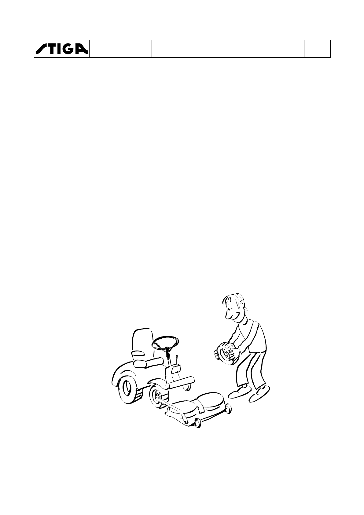
2. Remove the following parts from the
package and put them on the floor.
•
The battery (some models).
•
The steering wheel.
•
The plastic bag, containing owners manuals,
information media and assembly screws.

WORKSHOP MANUAL
PARK
1.3.2
The battery is a valve regulated battery.
Load and assemble the battery, following the
instructions below.
The battery needs limited maintenance. Is has
no electrolyte levels or plugs.
Charging with the engine
The battery can be charged using the engine’s
generator as follows:
1. Install the battery in the machine as shown
2. Place the machine outdoors or install an
3. Start the engine according to the
4. Allow the engine to run continuously for 45
5. Stop the engine. The battery will now be
Storage
Battery
Warning!
Do not wear rings, metallic bracelet,
chain round the neck or similar metal
objects when working with the
battery. It can cause short-circuit,
burns and fire.
Warning!
The battery must be fully charged be-
fore being used for the first time. The
battery must always be stored fully
charged. If the battery is stored while
discharged, serious damage will occur.
below.
extraction device for the exhaust fumes.
instructions in the user guide.
minutes.
fully charged.
1 - General instructions
Chapter
A
EDITION
2018
Page
5
If the cables are disconnected/
connected in the wrong order,
there is a risk of a short-circuit
and damage to the battery.
If the cables are interchanged,
the generator and the battery
will be damaged.
Charging using battery charger
When charging using a battery charger, a
battery charger with constant voltage
must be used.
The engine must never be driven
with the battery disconnected.
There is a risk of serious damage to the generator and the
electrical system.
The battery voltage is not allowed to drop under
12,5 V during storage.
Make sure that the battery voltage always is
more than 12,5 during storage. If not, the
battery will be destroyed.
Ordering number: 1136-0602-01.
The battery can be damaged if a standard
type battery charger is used.

WORKSHOP MANUAL
PARK
1 - General instructions
Chapter
EDITION
2018
Page
6
1.3.3
Final checks
Removing from pallet
All the above measures shall have been done with the machine standing on the pallet.
Now, loosen the remaining straps and roll off the machine from the pallet.
Fit and adjust accessories.
Test driving
Warning!
Do not drive without a work equipment (mover deck) attached. Risk for
turning over.
Drive the machine for a few minutes. Test all the functions. Pay special attention to the
safety functions. If the machine is to be delivered with mower deck or other accessories,
fit these before test driving the machine.
HST oil
Check the oil level in the HST’s expansion tank after test driving, and top up if
necessary.
Engine oil
Check the oil level in the engine and top up if necessary.
Steering chain / Steering wire
Check that the steering chain / steering wire is sufficiently taut. Adjust if necessary.
Miscellaneous
Give the machine a general inspection.
•
Is the machine clean?
•
Is there any oil leakage?
•
Abnormal noise or rattle?
Receipt
By filling in the guarantee certificate you guarantee that the delivery service has been
correctly conducted.
Remember to make sure that the customer receives all the documentation when the
machine is collected / delivered.

Service
Shall be performed
First service
Within 5 hours of running
Intermediate service
After the first 50 hours of running and then 50 hours after/before
Basic service
Every 100 hours or every year, which first occur.
Service
Shall be performed
First service
Within 5 hours of running
Intermediate service
After the first 100 hours of running and then 100 hours after/before
Basic service
Every 200 hours or every year, which first occur.
WORKSHOP MANUAL
PARK
1 - General instructions
Chapter
EDITION
2018
1.4 Service
Every new machine is delivered with a service book. This service book is part of the
active post-market programme and shall be kept in a safe place during the entire
lifetime of the machine. Hand over the service book if the machine is sold in 2:nd
hand.
Service should generally be carried out at least every 50 operating hours (exception
of the first service), although in accordance with the conditions below.
There are three different grades of service events. Every service event consists of a
number of service points as described in the following paragraphs. Every service
point has a number which refer to a describing text after the schedules.
The grades of service events are:
•
First service
•
Intermediate service
•
Basic service
Some service points do not coincide with the scheduled service intervals, but shall
be performed in connection with a scheduled service when possible. E.g. some items
shall be performed at every second service and some also between two services.
These service points are described with procedure and interval in the respective
“Instruction for use”.
Page
7
Typical service points wich not coincide with scheduled service intervals are:
•
Cleaning/changing air filter in some engines.
•
Change of oil in some engines.
•
Valve adjustments for some engines.
•
Change of transmission oil in 4 WD machines.
•
Change of spark plug in some engines.
1.4.1
Service times
Petrol driven machines
every basic service.
Diesel driven machines
every basic service.

Number
Service point
1
Safety check.
2
Tyres, air pressure.
3
Engine oil and filter, see “Engine - Transmission” at
page 14.
4
5
Belt transmissions, check.
6
Steering adjustment.
7
Battery check.
21
Number
Service point
1
Safety check.
2
Tyres, air pressure.
3
Engine oil and filter, see “Engine - Transmission” at
4
6
Steering adjustment.
9
10
Air filter catalytic converter, cleaning.
11
Cooling fins, clean.
12
Lubrication
WORKSHOP MANUAL
PARK
Chapter
1 - General instructions
EDITION
2018
Page
8
1.4.2
First Service
This service is very important to safeguard the continuing function of the machine.
The first service includes the service points as per the table below.
Oil level in HST, see “Engine - Transmission” at
page 14.
Test driving.
1.4.3 Intermediate Service
The intermediate service is not as extensive as the Basic Service and can therefore be
conducted by the customer, or by an authorised Service Workshop. Regardless of who
conducts the service, it must be documented in the service book..
page 14.
Oil level in HST, see “Engine - Transmission” at
page 14.
Air filter, cleaning.
Note!Ɩ¿»É»ÂºÈ¿Ì»Ä÷¹¾¿Ä»ÉƓ
Check/tighten engine support screwsupport screws every 100 hours.

Number
Service item
1
Safety check
2
Tires, air pressure
3
4
Oil level in HST, see “Engine - Transmission” at
page 14.
5
Belt transmissions, check
6
Steering adjustment
7
Battery check
8
Air filter for engine, see “Engine - Transmission” at
page 14.
9
Air filter catalytic converter, see “Engine -
(Valid for machines with catalytic converter only)
10
Cooling fins, clean
11
Spark plug, check/replace
13
Transmission, check
14
Speed check
15
Bearing boxes, check**
16
Exhaust system, check*
17
Electrical system, check*
18
19
Blades, check**
20
Power take-off, check
21
Control check
22
Valve play***
23
Test driving
WORKSHOP MANUAL
PARK
1 - General instructions
Chapter
EDITION
2018
1.4.4 Basic service
The Basic Service must always be conducted by an authorized Service Workshop,
and documented with a stamp in the service book.
Engine oil and filter, see “Engine - Transmission” at
page 14.
Page
9
Transmission” at page 14.
Mower deck, check**
*) See also “Safety check”.
**) See also the mover deck manual.
***) See the engine manual.
Note!Ɩ¿»É»ÂºÈ¿Ì»Ä÷¹¾¿Ä»ÉƓ
Check/tighten engine support screwsupport screws every 100 hours.

Test
Status
Action
Result
1 Brake pedal not pressed.
Turn the key and make a
Engine shall
2 Brake pedal pressed.
Turn the key and make a
Engine shall
3 Engine running.
Operator rises from the
Engine shall
4 Engine running.
Disconnect cable from the
Engine shall
stop after a few
Test
Status
Action
Result
1 Operator not sitting in seat.
Turn the key and make a
Engine shall
2 Brake pedal not pressed.
Turn the key and make a
Engine shall
3 Brake pedal pressed.
Turn the key and make a
Engine shall
4 Engine running.
Operator rises from the
PTO magnetic
5 Cruise control activated.
Operator rises from the
Cruise control
6 Engine running.
Disconnect cable from the
Engine shall
stop after a few
WORKSHOP MANUAL
PARK
1 - General instructions
Chapter
EDITION
2018
1.4.5 Description of service points
1. Safety check
Check the safety functions. It is often appropriate to do this check in conjunction with
test driving. The following items shall be checked at all machines:
•
No leakage on fuel lines and connections.
•
No mechanical damages to the electrical cables. All insulation intact.
•
The muffler shall be undamaged and its screws tightened. No exhaust leakage in
connections.
Machines with mechanic PTO
Page
10
PTO not activated.
PTO activated.
PTO activated.
Machines with electric PTO
Brake pedal pressed.
PTO not activated
PTO not activated.
PTO magnetic clutch activated.
start attempt.
start attempt.
seat.
shut off valve.
start attempt.
start attempt.
start attempt.
not start.
not start.
stop.
minutes.
not start.
not start.
not start.
PTO magnetic clutch activated.
(If applicable)
seat.
seat.
shut off valve.
clutch shall
disengage.
shall
disengage
minutes.

Test
Status
Action
Result
1 Operator not sitting in seat.
Turn the key and make a
Engine shall
2 Brake pedal not pressed.
Turn the key and make a
Engine shall
3 Brake pedal pressed.
Turn the key and make a
Engine shall
4 Engine running.
Operator rises from the
PTO magnetic
5 Hydraulic lift in neutral position.
Attempt to engage the
PTO magnetic
6 Engine running.
Disconnect cable from the
Engine shall
stop after a few
WORKSHOP MANUAL
PARK
Machines with electric PTO and hydraulic lift
Chapter
1 - General instructions
EDITION
2018
Page
11
Brake pedal pressed.
PTO not activated
PTO magnetic clutch not activated.
PTO magnetic clutch activated.
PTO magnetic clutch activated.
start attempt.
start attempt.
start attempt.
seat.
PTO magnetic clutch.
shut off valve.
not start.
not start.
not start.
clutch shall
disengage.
clutch shall not
engage.
minutes.

2 Tyres, air pressure
WORKSHOP MANUAL
PARK
Chapter
1 - General instructions
11 Spark plug
EDITION
2018
Page
12
Check the air pressure. Adjust if necessary.
The recommended air presure is
designated at the floor mat.
3 Engine oil and oil filter
See the “Instructions for use”, delivered
with the machine or “Instructions for use” at
page 31. See also the engine manufacturer
manual.
4 Oil, HST
See section 4 or the “Instructions for use”,
delivered with the machine.
5 Belt transmissions, check
Check the condition of all the belts and belt
tensioners.
6 Steering, adjustment
See section 3.
7 Battery, check
Valid for dry charged batteries only.
Check the acid level. Top up with distilled
water if necessary. See page 6-7.
8 Engine air filter
See the “Instructions for use”, delivered
with the machine. See also the engine
manufacturer manual.
9 Catalytic converter air filter
See the “Instructions for use”, delivered
with the machine. See also the engine
manufacturer manual.
10 Cooling fins
Remove protective covers from the engine
and cleans between cooling fins. Use a
brush and compressed air. See also the
engine manufacturer manual.
Remove the spark plug (not valid for Pro
Diesel) and clean it or replace if necessary.
See also the engine manufacturer manual.
12 Lubrication
Lubricate the articulation point (4 nipples)
and all moving parts such as wires and
levers. See also the instruction manual,
delivered with the machine.
13 Transmission
Listen for abnormal noise.
Manual models: Check that the drive
function works properly at all gears. Adjust
if required.
14 Speed check
Check that the speed corresponds to the
specified value. See pages 18-22.
15 Bearing boxes
Listen for abnormal noise from the
bearings. Check that there are no wear,
play or seizure.
16 Exhaust system
Check that there are no cracks, leakage or
other damages. Check the attachment
devices. See also the engine
manufacturer manual.
17 Electrical system
Check that there are no damaged cables,
contacts or other devices. Check that all
cables are properly secured to the chassis
and with cable holders. Check that there is
no friction between cables and chassis,
which can result in cable damage and
short circuit.

WORKSHOP MANUAL
PARK
1 - General instructions
Chapter
EDITION
2018
Page
13
18 Mower deck
Warning!
The blades are sharp. Always
wear gloves when working with
the blades to avoid injury.
Check if there are collision damages or
wear at the deck body and painting. Align,
repair and touch up the painting as
required.
Check the tightening of the bearing boxes
screws and tighten.
Rotate the blades and check the the shafts
are correct, not bent, no abnormal bearing
noise and no plays.
Check the belts and their tensions, see
section 4.
Check that the lifting mechanism moves
evenly, not jammed and no play and that it
locks in desired position.
Check the electrical function of the
electrikal mower lifter (if applicable).
Check the plastic guide bar between the
blades. Replace if required.
19 Blades
Warning!
The blades are sharp. Always
wear gloves when working with
the blades to avoid injury.
Check that the blades are sharp. Sharpen
as reqiured.
20 Power take-off (PTO)
Check that the magnetic clutch (if
applicable) engage the work equipment
rotation in the desired time and that it not
slips during normal load. Replace the
clutch if necessary.
Check that the power take-off belt (if
applicable) engage the work equipment
rotation in the desired time and that it not
slips during normal load. Adjust if
necessary. See section 4.
Check that the power take-off brake (if
applicable) brakes the rotation movement
in the desired time. Adjust if necessary.
See section 4.
21 Control check
Check that all controls function properly,
that there are no jammings or excessive
plays. Adjust if nesaccary. See section 5.
22 Valve play
See the engine manual regarding
procedure and interval.
23 Test driving
Drive the machine during a few minutes
and make the following attentions in
different speeds and turnings in right and
left. Check that all functions work evenly
and proper and without any abnormal
noise.
•
Brake function
•
Clutch function
•
Power take-off
•
Steering
Check that there are no abnormal
vibrations.

Machine
Transmission
Oil and filter change interval
Oil volume
Oil grade
Description
Number
1:st time
Thereafter
Park 2WD
K46
1137-0123-01
Park Compact
Park CH 2WD
Park CH 4WD
Park Pro 4WD
KTM10G
1134-5701-01
KTM10F
1134-5702-01
KTM-13
118475000/0
5 h
200 h
4,7 Liter
5W-50
Thread
Torque
M5
5,7 Nm
M6
9,8 Nm
M8
24 Nm
M10
47 Nm
WORKSHOP MANUAL
PARK
1 - General instructions
Chapter
1.5 Transmission
1.5.1 Transmission oil and filter change interval
Below is listed oil and filter data for the transmissions.
-
and CH 4WD
without servo
with servo
with servo
K574G 1137-0124-01 5 h 200 h 3,5 Liter
KTM10M 1134-6029-01
K57-V 1137-0126-01
K574F
KTM10M
KPL 10ALP 1134-5700-01 5 h 200 h 4,2 Liter
1137-0125-01
1134-6029-01
-
-
1,3 Liter
3,6 Liter
EDITION
2018
SAE 10W-30
(20W-50)
Synthetic oil
5W-50
Synthetic oil
5W-50
Synthetic oil
5W-50
Synthetic oil
5W-50
Page
14
1.6 Technical specifications
1.6.1 General tightening torque
Unless otherwise stated, the following
tightening torque are applicable for screws and
nuts on the machine:
Tightening torques
1.7 Instructions for use
Synthetic oil
Some procedures, e.g. changing engine oil,
engine filter etc., are refered to the owner´s
manual, delivered with the actual machine.
The owner´s manual can also be downloaded
from STIGA´s homepage. Go to www.STIGA.com
and click further to your actual language and
heading.
WORKSHOP MANUAL
PARK
2 - Chassis and body
Chapter
EDITION
2018
2 Chassis and body
Contents in this chapter
2.1 Rear wheel ........................................ 2
2.1.1 Assembly ....................................... 2
2.2 Lubrication chassis .......................... 3
2.3 Hydraulic pump ................................ 4
2.3.1 Dismantling .................................... 4
2.3.2 Assembly ....................................... 6
General
To facilitate the driving, handling of work equipment and to make it comfortable for the
driver, the machines are equipped with a various number of aid equipments. These
equipments are mainly the same for all the machines covered by this manual, but in some
cases configurated in different ways. Where divergences occour between the machines,
particular instructions are given for each particular equipment.
Page
1
This chapter gives a brief description of the equipments and describes their repair and
replacements.
2.1
WORKSHOP MANUAL
PARK
Rear wheel
Chapter
2 - Chassis and body
EDITION
2018
Page
2
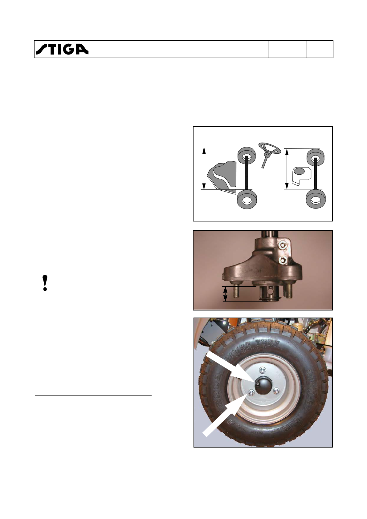
2.1.1
1. Push the hub on the shaft until it rests
2. Assemble the washer and the circlip onto the
3. Check the key and assemble it in the groove,
4. Assemble the rear wheel without tightening
5. Measure the distance (X) between the front
Assembly
against the transmission body.
shaft. The washer shall rest against the
circlip.
against the washer.
the nuts.
wheels and adjust the rear hubs until the
distance between the rear wheels is the
same (X).
Pull out the hubs until the measure (Y) is the
same at the both sides.
Note!
If the measures between the wheels front
and rear not is the same, the machine will
be hard to steer.
X
X
Y
6. Tighten the two allen screws, using a 8 mm
allen key.
The tightening shall be performed in two
steps. Tighten first to 18 Nm and then, finally
to a torque of 24 Nm.
7. Assemble the rear wheel and the protecting
cover.
Asembly when tyre chains are used
To give place for the tyre chains, the distance X
can be increased. If necessary until the hub
rests against the washer.
15/17 mm box spanner
WORKSHOP MANUAL
PARK
2.2
Lubrication chassis
The bearing for the articulation must be
lubricated in accordance with the service
schedule. Other moving parts are lubricated
once per season, although at least every 50
operating hours.
Note!
Lubrication is equally important for a
machine that is only used for a few hours
per year.
Note!
The lubricant provides not only
protection from wear but also from rust.
Note!
The machine should always be
lubricated before prolonged storage.
The bearing for the articulation has four grease
nipples which must be lubricated with universal
grease.
The steering chain must be lubricated with
chain spray two or three times per season.
If the chains are heavily fouled: dismantle the
chains and wash them.
Refit and lubricate them.
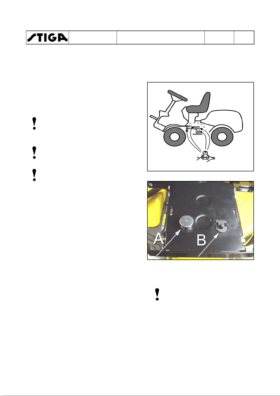
The pressure pin (A) in the seat suspension
must be lubricated to avoid problems with the
safety circuit.
Plastic bearings, e.g. the brake pedal bearing,
hydrogear pedal bearing and steering-column
bearing, must be lubricated with grease or
lubricating spray.
Drop a little engine oil or lubricating spray in the
ends of the control wires two or three times a
year.
Chapter
2 - Chassis and body
Note!
Wires on machines used in
freezing conditions should not be
lubricated with engine oil since
this can lead to the control cables
seizing in the cold.
The wires on such machines
should be lubricated with a
fluent, strongly penetrating
lubricant, e.g. 5-56 or WD40.
EDITION
2018
Page
3
WORKSHOP MANUAL
PARK
2.3
Hydraulic pump
This section will describe the replacement
procedure for the external hydraulic pump in
4WD Park machines.
2.3.1
Dismantling
1. Remove the battery. See the owners
manual.
2. Block up the machine. Use a lifting table or
highjack and yokes.
3. Activate the parking brake.
4. Discharge the oil in the hydraulic system.
See the owners manual.
Chapter
2 - Chassis and body
EDITION
2018
Page
4
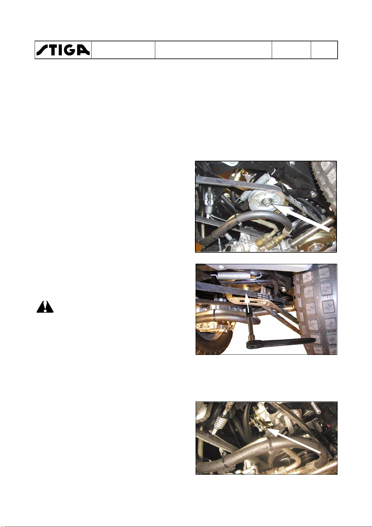
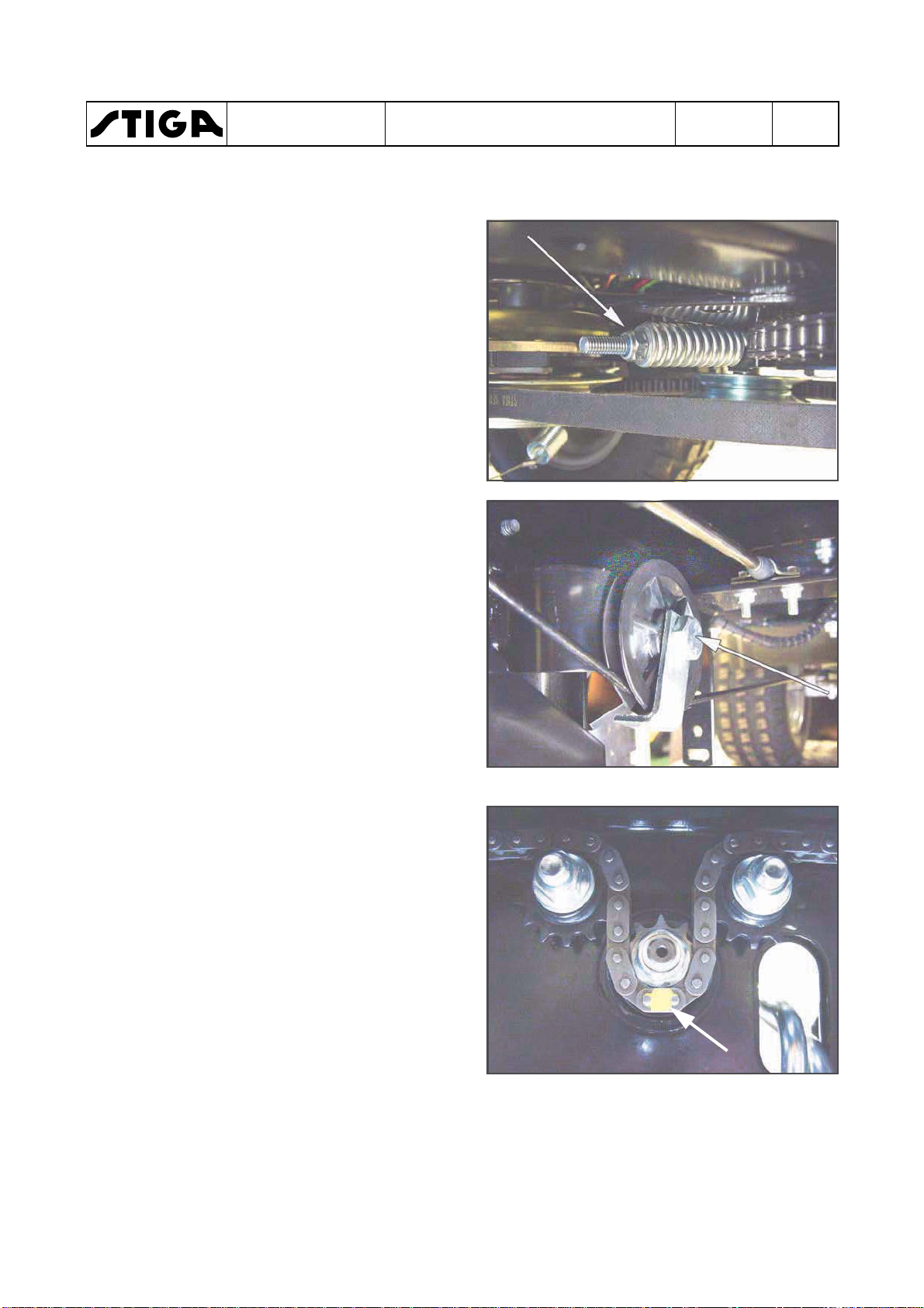
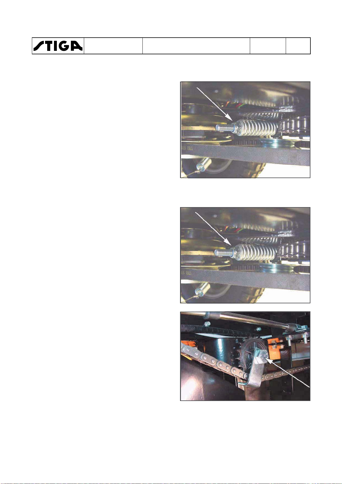
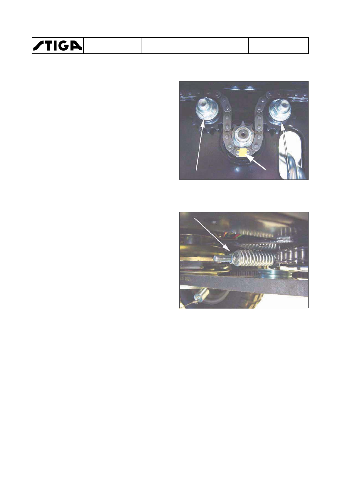
5. Remove the tension pulley by using a 15 mm
and a 17 mm spanner. See the figure.
6. Use a large polygrip and hold the pump
pulley in a securely grip. Fit the polygrip
around the belt, not direct to the pylley.
Back off the pulley nut with a 17 mm sleeve.
See the figure.
Warning!
Be carefully not to damage the
plastic fan during the removal.
7. Remove the following parts from the pump
shaft:
•
Nut
•
Washer
•
Pulley
•
Distance sleeve
•
Fan
•
Distance sleeve
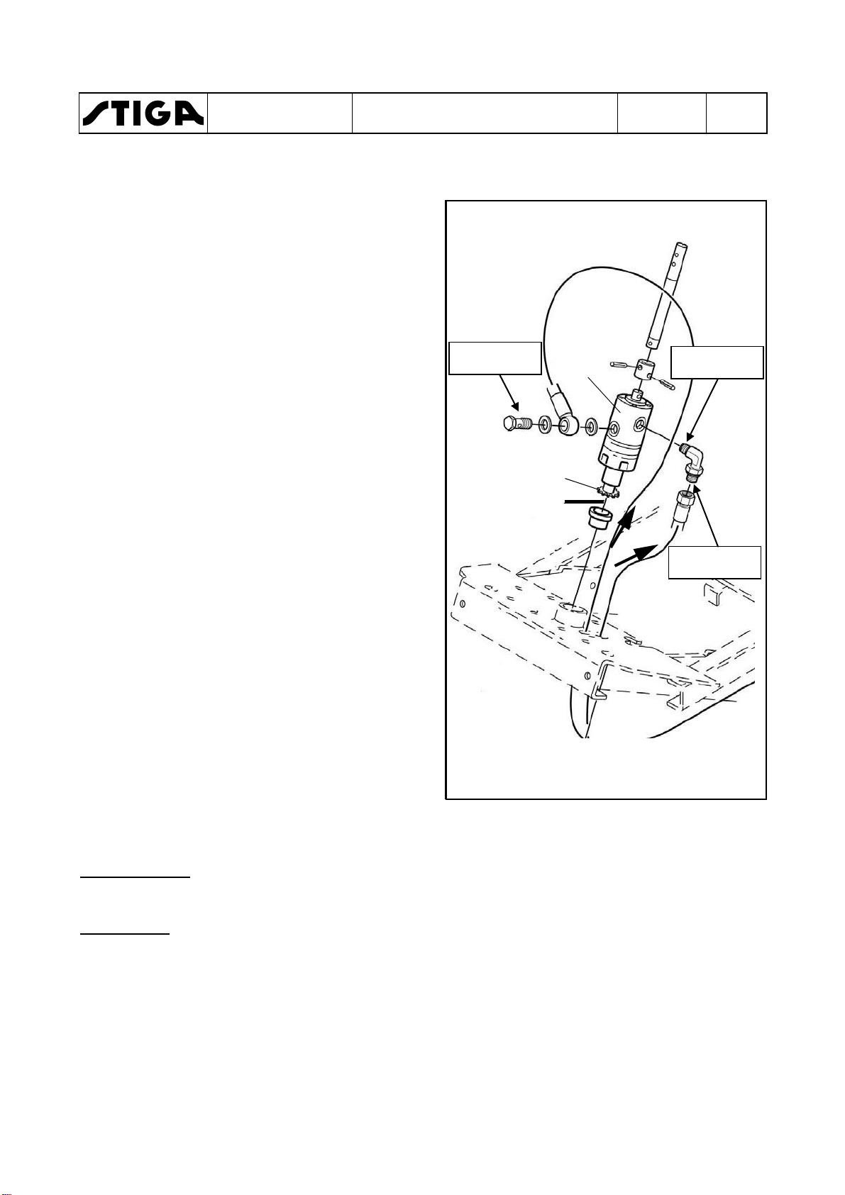
8. Remove the speed control cable from the
hydraulic pump by backing off the nut. Use a
8 mm spanner. See the figure.
9. Back off the circlip from the release lever rod
and disconnect the rod from the lever.
40 Nm
78 Nm
78 Nm
40 Nm
B
40 Nm
A
78 Nm
WORKSHOP MANUAL
PARK
10. Place a collecting tray under the pump for
collecting residual oil from the pump and
hoses.
Warning!
Do not spill any oil on the drive belts
during the disconnection of hoses
and tubes.
Warning!
Keep clean when handling hydraulic
parts. Dirt in the oil will cause
malfunctions and breakdowns.
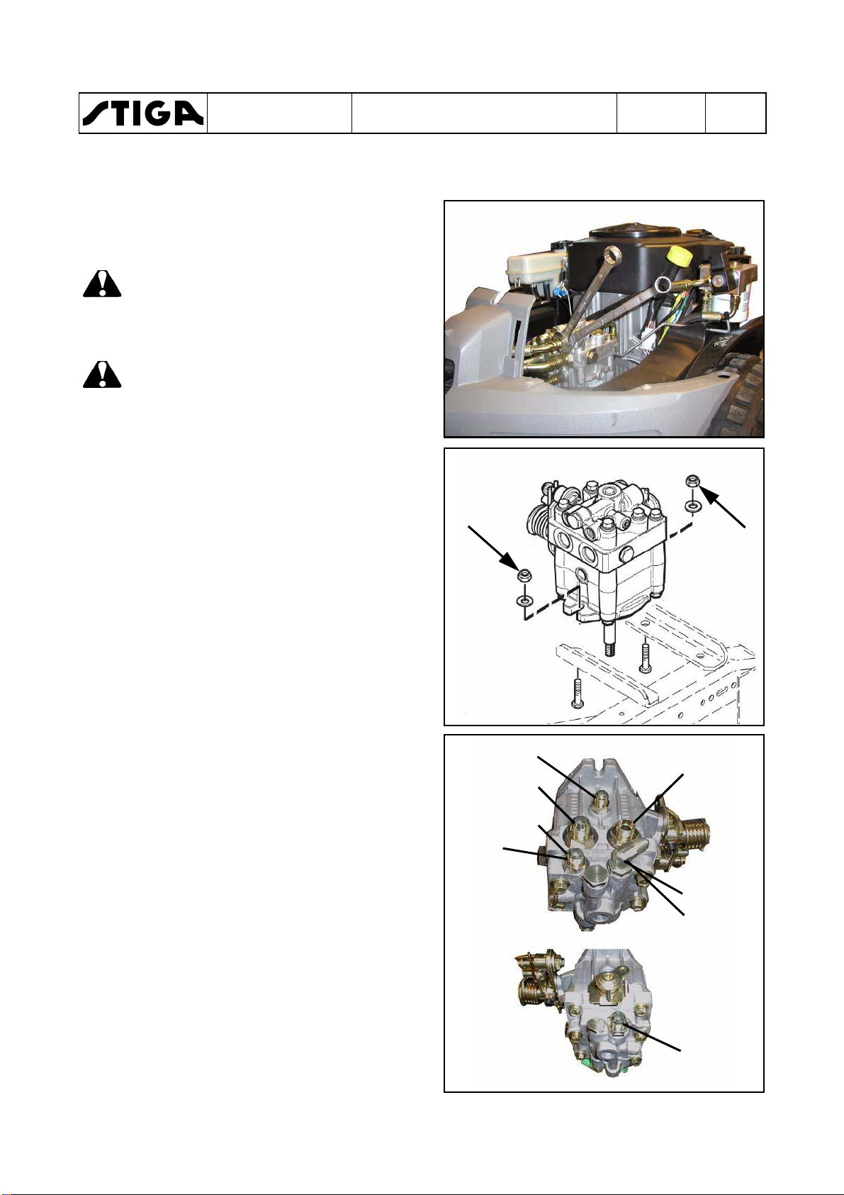
11. Disconnect all hoses and tubes from the
hydraulic pump. Always use two spanners,
one to hold the respective connection in the
pump and one to loosen the nut. See the
figure.
Chapter
2 - Chassis and body
EDITION
2018
Page
5
12. Remove the pump from the chassis by
unscrewing the two M10 mounting nuts and
screws. Use two 17 mm spanners. See the
figure.
13. Place and fasten the pump in a table vice.
Loosen the adapters from the pump.
14. Screw out the adapters and insert them in
the corresponding places in the new pump
one at a time. Check or replace the O-rings.
3. Place and fasten the new pump in a table
vice. Tighten the adapters to torques
according to the figures.
When tightening the angle adapter (A),
adjust it to 45° according to the horizontal
line. Use one 14 mm and one 19 mm
spanner.
If a metal tube shall be fitted to the adapters
A and B (machines without external
hydraulics), the connection nuts shall be
tightened with 41 Nm.

WORKSHOP MANUAL
PARK
2 - Chassis and body
Chapter
EDITION
2018
Page
6
2.3.2
Assembly
Warning!
Keep clean when handling hydraulic
parts. Dirt in the oil will cause
malfunctions and breakdowns.
Warning!
Be carefully not to damage the
plastic fan during the assembly.
Assemble all parts in the reverse order.
Note!
One distance sleeve (C) at each side of
the fan.
Note!
The tension pulley (D) shall be fitted with
the prolonged part of the sleeve
upwards. See both figures.
C
C
D
Adjust the speed cable. See section 6.
When all parts are fitted and all actual
tightening torques are applied, fill new oil and
bleed the hydraulic system. See the owners
manual.
Up
D

WORKSHOP MANUAL
PARK
3 Steering
Contents in this chapter
3.1 Description ....................................... 2
3.1.1 Mechanical system ........................ 2
3.1.2 Hydraulic assisted system ............. 2
3.2 Steering wires ................................... 4
3.2.1 Replacement ................................ 4
3.2.2 Adjustment .................................... 5
3.2.3 Steering chains .............................. 5
General
Chapter
3 - Steering
EDITION
2018
Page
1
3.3 Bearings, steering shaft .................. 7
3.3.1 Replacement of sliding bearings
and ball bearings .................................... 7
3.3.2 Replacement of upper ball bearing
(with steering booster) ............................ 8
3.3.3 Trouble shooting ............................ 9
The articulation steered machines are equipped with either a common mechanical system
or a hydraulic assisted steering system. Both systems work with wires or chains,
depending on the model. The hydraulic assisted system gets its power from the variable
hydraulic transmission at the rear shaft.
This chapter contains a brief description of the function and describes repair, replacements
and adjustments of stressed parts of the steering system.
3.1
WORKSHOP MANUAL
PARK
Description
Chapter
3 - Steering
EDITION
2018
Page
2
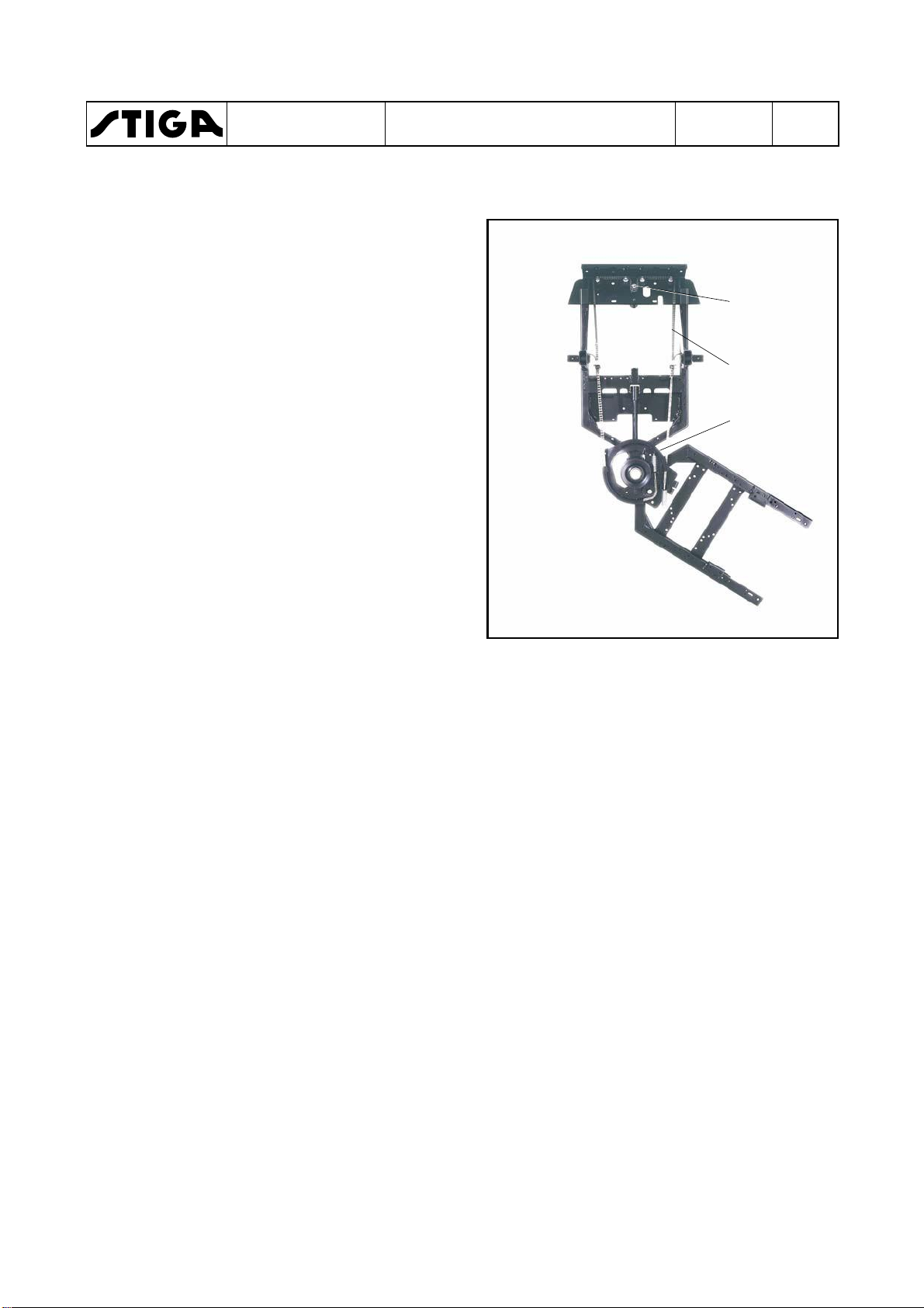
3.1.1
The sprocket (A) is directly coupled to the
stering wheel on the same shaft. A chain (and
wires) (B) is engaged with the sprocket and
connected to the steering disc (C) on the rear
frame. Thus, the rear frame is forced into actual
angles, related to the front frame when the
driver turns the steering wheel.
3.1.2
Below is given a brief description about how the
steering torque converter works and its
connection to the valves. For a complete
description, see section 4 “Hydraulic system”.
Section 4 describes how the lifting cylinder
works together with the steering torque
converter. It also describes the pressure
division between the two systems and
adjustments.
The power assisted steering is a hydraulic
auxiliary system. The main components are the
torque converter and the oil pump in the
hydrogear.
Mechanical system
Hydraulic assisted system
A
B
C
As opposed to standard power steering (e.g. in
a car), this power assisted steering has a
limited capacity. This implies that in certain
circumstances it has what may be experienced
as negative characteristics.
At low engine speed, or in situations where
extra steering power is required, the steering
may be considered to be somewhat jerky.
The machine should always be in motion when
the steering is used. Avoid turning the steering
wheel when the machine is standing completely
still and the accessory is in lowered working
position.
The machine can be steered even when the
engine is switched off. Nevertheless, it may
require more force than normal to steer the
Md D
A
Ms
Mh
Md+Mh=Ms
35-42 Nm
35-42 Nm
30-37 Nm
WORKSHOP MANUAL
PARK
machine. This is particularly noticeable during
cold weather.
Mainly, the hydraulic assisted system works
similar to the mechanical system. The different
is a torque booster (D), atttached to the steering
shaft between the steering wheel and the
sprocket (A).
A oil flow from the HST is flowing through the
torque booster via a filter.
As the driver turns the steering wheel, there
occour a pressure drop over the torque booster.
The pressure drop, multiplied with the flow,
gives a moment (Ma), which is added to the
moment from the driver (Md) and applied on the
sprocket (A) as a moment (Ms).
Chapter
3 - Steering
EDITION
2018
Page
3
The following items are shown in the figure:
A Sprocket of driving the steering chain.
D Torque booster.
Mh Steering power (moment) from the
hydraulic transmision.
Md Hand power (moment) from the driver.
Ms The sum of Ma and Md as steering power
(moment on sprocket A).
Hydraul connections
The hydraul lines have two alternative
connections:
•
Pressure plate with O-rings around the tubes.
•
Banjo fitting.
Pressure plate
Always mount new O-rings when assembling.
Banjo fitting
The connection have no gaskets.
Always tighten the nipples with the correct
tightening when assembling. See the figure.
WORKSHOP MANUAL
PARK
3.2 Steering wires
3.2.1 Replacement
1. Loosen the nuts on the steering wire. Brace
with a spanner so that the wire does not
rotate.
2. Loosen the screws that hold the pulley so
that the wire can be taken out between the
pulley and the wire retainer.
Chapter
3 - Steering
EDITION
2018
Page
4
3. Unhook the chain at the front chain sprockets.
It can sometimes be easier to get the chain
off by slightly unscrewing the screws that
hold the chain sprockets.
4. Measure up the middle link (mark A) on the
new chain and mark it.
5. Place the chain on the chain sprockets.
Make sure that the wheel is straight and that
the marked middle link is placed on the middle of the chain sprocket.
6. Place the wire in the pulley and tighten the
screws to the wire retainers.
7. Fit the washer and nut on the threaded rear
ends of the steering wire.
A
WORKSHOP MANUAL
PARK
3.2.2 Adjustment
1. Tension the wire nuts equally on both sides
so that the wheel is straight when the
machine is straight.
Brace with a spanner so that the wire does
not twist.
2. Turn the wheels fully out in both directions.
Check that the chain does not go into the
pulley and that the wire does not go into the
chain sprocket.
3. Test drive. Check the tension of the wire
after test driving.
Chapter
3 - Steering
EDITION
2018
Page
5
3.2.3 Steering chains
1. Loosen the nuts on the steering chain.
2. Loosen the screws that hold the chain
sprockets so that the chain can be taken out
between the chain sprocket and wire
retainer.
3. Unhook the chain at the front chain
sprockets.
It can be easier to get the chain off by slightly
unscrewing the screws that hold the chain
sprockets.
WORKSHOP MANUAL
PARK
4. Measure up the middle link (A) on the new
chain and mark it.
5. Place the chain on the chain sprockets.
Make sure that the wheel is straight and that
the marked middle link (A) is placed on the
middle of the chain sprocket.
6. Place the wire on the chain sprockets and
tighten the screws to the wire retainers.
7. Fit the washer and nut on the threaded rear
ends of the steering chain.
8. Adjust as described below.
Chapter
3 - Steering
EDITION
2018
A
Page
6
Adjustment
1. Tension the nuts equally on both sides so
that the wheel is straight when the machine
is straight.
2. Turn the wheels fully out in both directions.
Check that there is no abnormal noise or
abnormal resistance.
3. Test drive. Check the tension of the chain
after test driving.
WORKSHOP MANUAL
PARK
3.3 Bearings, steering shaft
The steering shaft bearings are configurated in
one of the following three ways:
• Two sliding bearings of the composite type.
• Two sealed ball bearings.
• One sealed ball bearing (upper) and one ball
bearing in the torque booster (lower).
3.3.1 Replacement of sliding bearings
and ball bearings
1. Remove the chain from the lower sprocket.
See previous sections.
2. Tap out the spring pin that holds the steering
wheel. Remove the steering wheel.
Chapter
3 - Steering
EDITION
2018
Page
7
3. Pull up the parking brake knob, remove the
upper cover and the lamp section.
4. Remove the to screws, holding the steering
column and remove the steering column (A).
5. Tap out the bearings with a long drift, bar or
similar.
6. Tap in the new bearings with a rubber mallet.
A
7. Reassemble in the reverse order and adjust
the chain/wire. See previous sections.

WORKSHOP MANUAL
PARK
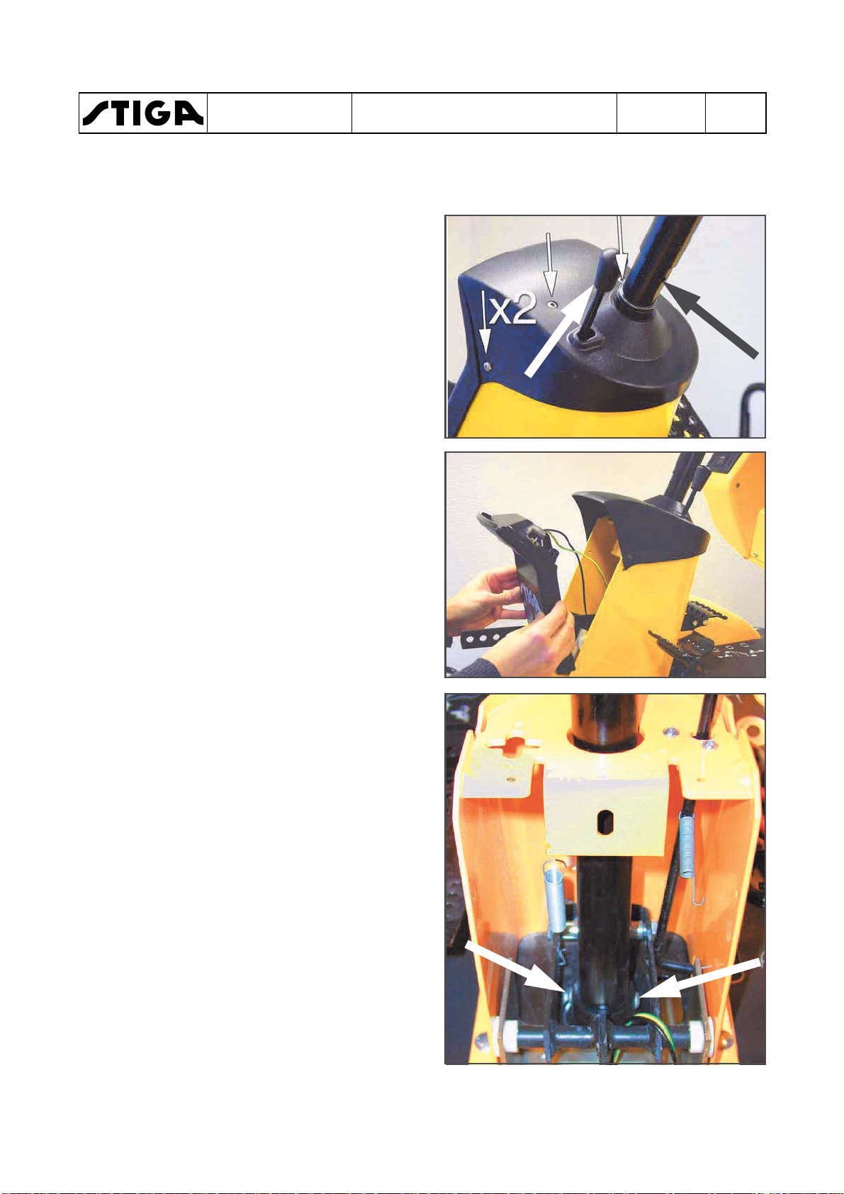
3.3.2 Replacement of upper ball bear-
ing (with steering booster)
1. Tap out the spring pin that holds the steering
wheel. Remove the steering wheel.
2. Pull up the parking brake knob, remove the
upper cover and the lamp section.
Note!
Do not forget the washer (G).
The correct number of shims must be
used to avoid tensions in the steering
column.
3. Remove the split pin from the hydraulic lift
bolt (A) and push out the bolt.
4. Remove the spring (B).
Chapter
3 - Steering
A
EDITION
2018
Page
8
5. Remove the four nuts (C) from the underside and the screw (E), holding the steering
console (F) and lift out the steering console
with its four screws.
6. Remove the three M8-screws (I) from the
lower steering tube (D) and pull up the
steering tube with the washer (G).
7. Press or knock out the ball bearing (H) from
the steering tube and assemble a new bearing with help of a rubber mallet.
8. The assembling is performed in the reverse
order.
Note!
Do not forget the washer (G).
The correct number of shims must be used
to avoid tensions in the steering column.
C
D
E
B
F
G
H
I
 Loading...