

Page 1

WORKSHOP MANUAL
PARK
2008 - 201ˀ
Page 2

TABLE OF CONTENTS
1 - General instructions
2 - Chassis and body
3 - Steering
4 - Hydraulic system
5 - Belts
6 - Control Wires
7 - Electrical System
All brands, names, logos and trademarks mentioned belong to their respective owners.
© by STIGA - No use of the illustrations or duplication, reproduction or translation, even partial, of the texts in this
document may be made without explicit authorisation.
Page 3
WORKSHOP MANUAL
PARK
1 General instructions
Contents in this chapter
Chapter
1 - General instructions
EDITION
2018
Page
1
1.1 Introduction ...................................... 2
1.1.1 Responsibility declaration .............. 2
1.1.2 How this manual is used ................ 2
1.1.3 Abbreviations ................................. 2
1.2 Safety Precautions ........................... 2
1.2.1 Symbols and warnings .................. 3
1.2.2 Warm parts .................................... 3
1.2.3 Moving parts .................................. 3
1.2.4 Lifting and blocking up ................... 3
1.2.5 Cleanliness .................................... 3
1.2.6 Tightening torque ........................... 3
1.2.7 Sharp edges .................................. 3
1.2.8 Replacement parts ........................ 3
1.2.9 Inspection ...................................... 3
1.3 Unpacking and assembly ................ 4
1.3.1 Unpacking ..................................... 4
1.3.2 Battery ........................................... 5
1.3.3 Final checks .................................. 6
1.4 Service .............................................. 7
1.4.1 Service times ................................. 7
1.4.2 First Service .................................. 8
1.4.3 Intermediate Service ..................... 8
1.4.4 Basic Service ................................ 9
1.4.5 Description of service points ....... 10
1.5 Transmission .................................. 14
1.5.1 Transmission oil and filter change
interval .................................................. 14
1.6 Technical specifications ................14
1.6.1 General tightening torque ............. 14
1.7 Instructions for use ........................ 14
General
This Workshop Manual covers all Park – Park Pro models from 2008. The Park 120-220
have a separate workshop manual. The Park Pro models from 2015 with steering cylinder
have a separate workshop manual.
This Manual do not cover repair instructions for the engines. Regarding engines, contact
the respective representative in the actual country.
This Manual and its specifications are valid for machines in their original design. In case of
modified or changed machine, i.e. the engine is replaced, the manual accordance is limited.
The manual is divided in the following chapters:
Chapter 1 is this chapter
Chapter 2 Chassis
Chapter 3 Steering
Chapter 4 Hydraulic system
Chapter 5 Belts
Chapter 6 Control Wires
Chapter 7 Electrical system
Page 4

1.1
WORKSHOP MANUAL
PARK
Introduction
Chapter
1 - General instructions
EDITION
2018
Page
2
1.1.1
In spite of the great care we have taken there may be errors in this publication.
The author cannot be made liable for incorrect or missing information.
STIGA reserves the right to regularly change product specifications without prior notice.
All the information in this book is based on the information available at the time of
production. Illustrations and photographs may be arranged schematically, which implies
that one picture may cover several models and therefore not correspond exactly with all
models.
1.1.2
To make this manual easy to understand we have divided the machine into its main
systems and components. These parts are now the different chapters in the book.
Each chapter is divided up into sections.
There is a quick-guide on the cover of this book, which refers to the different chapters. In
each chapter there is a detailed table of contents so that you can easily and quickly find
what you are looking for.
Always check that you are reading the right chapter for your particular machine before
starting the repair work.
1.1.3
Responsibility declaration
How this manual is used
Abbreviations
The following abbreviations are used in this manual:
HST Hydrostatic Transmission PTO Power Take Off
1.2
Safety Precautions
This manual has been written primarily for trained mechanics working in a well-equipped
workshop.
A basic knowledge of repairs, tools and repair instructions is, however, always a
prerequisite for first-rate results.
A qualified mechanic should always be consulted if the owner does not have sufficient
knowledge to carry out repairs.
During the warranty period all service must be carried out by an Authorised Workshop for
the warranty to be valid.
The following basic points should be observed if the machine is to function perfectly:
•
Follow the service schedule.
•
Be on the alert for sudden vibrations or abnormal noise to avoid major breakdowns.
•
Always use Genuine Spare Parts
•
Follow the descriptions in this manual carefully. Do not take any short cuts.
Page 5

WORKSHOP MANUAL
PARK
1 - General instructions
Chapter
EDITION
2018
Page
3
1.2.1
Symbols and general warnings
Warning!
This symbol indicates a risk of
personal injury or damage if the
instructions are not followed.
Note!
This text indicates a risk of damage to
the material or risk of unnecessarily
complicated work if the instructions
are not followed.
1.2.2
Please observe that engine and exhaust
system picks up a lot of heat during use.
This applies above all to the silencer of
machines equipped with catalytic
converter.
To avoid injuries, allow the machine to cool
before any kind of repairs are made to or
near parts of the engine or exhaust
system.
1.2.3
The machines are all equipped with v-belt
transmissions. Always stop the engine and
remove the starter key before inspections
or repairs are carried out.
Always use extreme caution when testing
systems with moving parts to avoid
injuries.
Always use Genuine Spare Parts during
service work.
1.2.4
Warm parts
Moving parts
Lifting and blocking up
1.2.5
Clean the machine before starting repairs.
Dirt that penetrates into sensitive
components can seriously influence the
service life of the machine.
1.2.6
Unless otherwise stated the tightening
torque in the tables in the section
Technical specifications must be used for
the different sizes of screws. This does not
refer to self-tapping screws, which are
mainly used for the assembly of body
parts.
1.2.7
Watch out for sharp edges, especially
when working with the mower deck. The
blades can be very sharp. Always wear
gloves when working with the blades.
1.2.8
Always use Genuine Spare Parts during
service work.
1.2.9
Each part dismantled in conjunction with
service work must be inspected.
Examine for: wear, cracks, out of
roundness, straightness, dents,
discolouring, abnormal noise and
jamming.
Cleanliness
Tightening torque
Sharp edges
Replacement parts
Inspection
Before work under the machine, always
make sure that lifting devices and jackstands are approved for the weight.
Work safe!
Page 6
WORKSHOP MANUAL
PARK
1 - General instructions
1.3 Unpacking and assembly
Every STIGA Park has undergone an extensive
control programme before delivery. The
machines are delivered as completely
assembled as possible.
Thanks to this the assembly on delivery is rapid
and easy.
The correct and careful assembly of the
machine on delivery is a simple way of ensuring
satisfied customers!
Note!
The machine shall remain placed on the
pallet during the unpacking and
assembly.
1.3.1 Unpacking
Chapter
EDITION
2018
Page
4
Open up the crate and release the part as
follows:
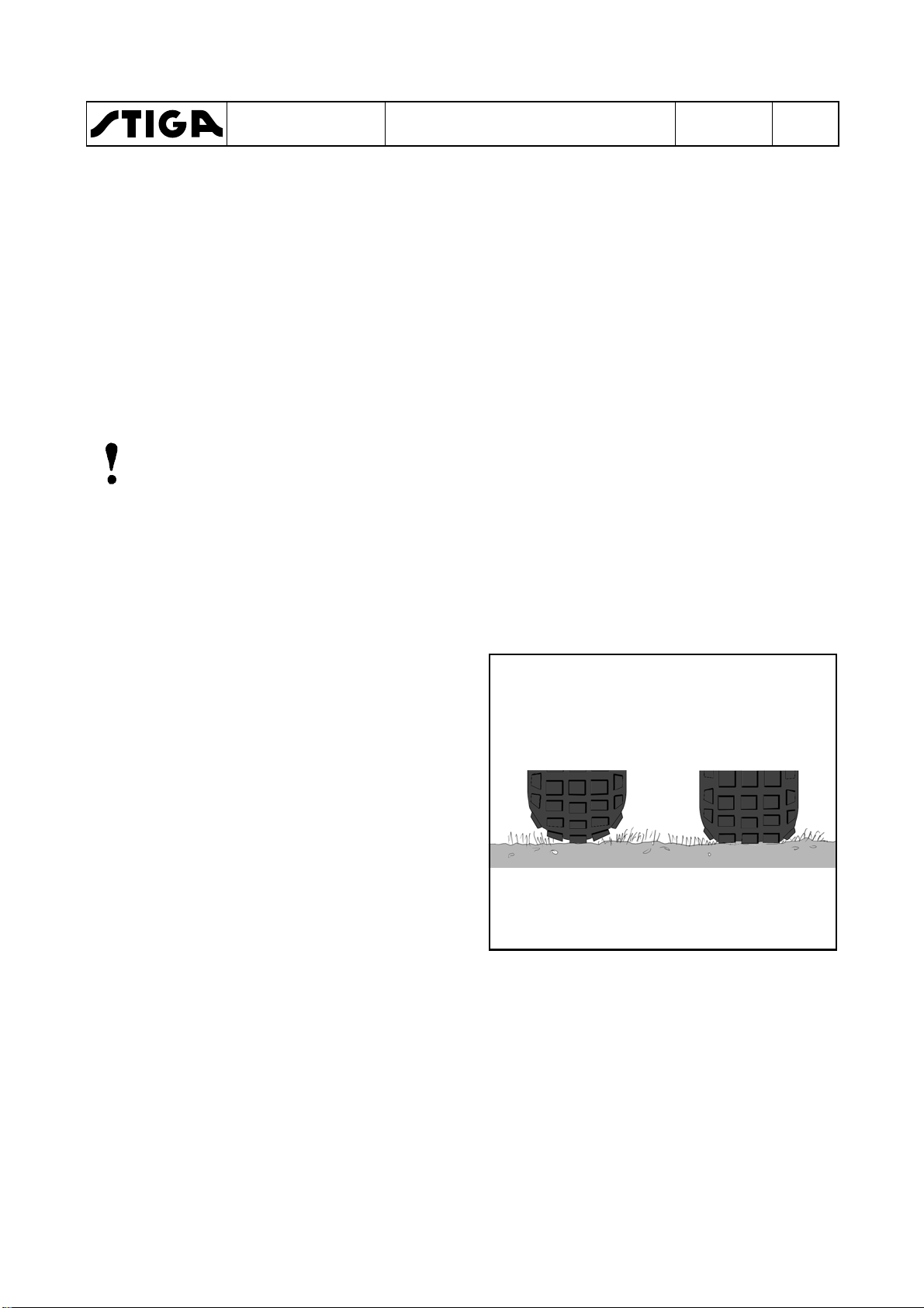
1. Check the air pressure in the tyres. The
pressure is designated on the floor mat.
The air pressure in the tyres is of critical
importance for the performance and
handling of the machine. The correct air
pressure for mowing is 0.6 bar (9 psi) in the
front tyres, and 0.4 bar (6 psi) in the rear
tyres.
When using heavy accessories, e.g. snow
thrower, it may be necessary to increase the
pressure somewhat. However, the
maximum permitted pressure is always
0.8 bar (12 psi).
Too high pressure Correct pressure
Too high pressure in the tyres leads to that
the machine drives poor due to:
•
A small surface in contact to the ground.
•
Hard tyre = less flexibility = self cleaning characteristic deteriorate.
2. Remove the following parts from the
package and put them on the floor.
•
The battery (some models).
•
The steering wheel.
•
The plastic bag, containing owners manuals,
information media and assembly screws.
Page 7

WORKSHOP MANUAL
PARK
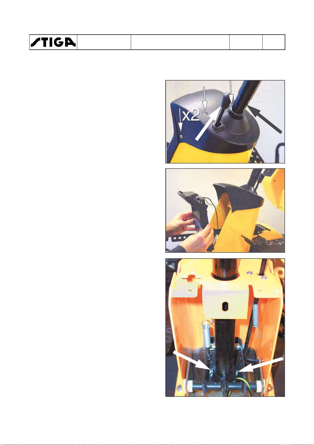
1.3.2
The battery is a valve regulated battery.
Load and assemble the battery, following the
instructions below.
The battery needs limited maintenance. Is has
no electrolyte levels or plugs.
Charging with the engine
The battery can be charged using the engine’s
generator as follows:
1. Install the battery in the machine as shown
2. Place the machine outdoors or install an
3. Start the engine according to the
4. Allow the engine to run continuously for 45
5. Stop the engine. The battery will now be
Storage
Battery
Warning!
Do not wear rings, metallic bracelet,
chain round the neck or similar metal
objects when working with the
battery. It can cause short-circuit,
burns and fire.
Warning!
The battery must be fully charged be-
fore being used for the first time. The
battery must always be stored fully
charged. If the battery is stored while
discharged, serious damage will occur.
below.
extraction device for the exhaust fumes.
instructions in the user guide.
minutes.
fully charged.
1 - General instructions
Chapter
A
EDITION
2018
Page
5
If the cables are disconnected/
connected in the wrong order,
there is a risk of a short-circuit
and damage to the battery.
If the cables are interchanged,
the generator and the battery
will be damaged.
Charging using battery charger
When charging using a battery charger, a
battery charger with constant voltage
must be used.
The engine must never be driven
with the battery disconnected.
There is a risk of serious damage to the generator and the
electrical system.
The battery voltage is not allowed to drop under
12,5 V during storage.
Make sure that the battery voltage always is
more than 12,5 during storage. If not, the
battery will be destroyed.
Ordering number: 1136-0602-01.
The battery can be damaged if a standard
type battery charger is used.
Page 8

WORKSHOP MANUAL
PARK
1 - General instructions
Chapter
EDITION
2018
Page
6
1.3.3
Final checks
Removing from pallet
All the above measures shall have been done with the machine standing on the pallet.
Now, loosen the remaining straps and roll off the machine from the pallet.
Fit and adjust accessories.
Test driving
Warning!
Do not drive without a work equipment (mover deck) attached. Risk for
turning over.
Drive the machine for a few minutes. Test all the functions. Pay special attention to the
safety functions. If the machine is to be delivered with mower deck or other accessories,
fit these before test driving the machine.
HST oil
Check the oil level in the HST’s expansion tank after test driving, and top up if
necessary.
Engine oil
Check the oil level in the engine and top up if necessary.
Steering chain / Steering wire
Check that the steering chain / steering wire is sufficiently taut. Adjust if necessary.
Miscellaneous
Give the machine a general inspection.
•
Is the machine clean?
•
Is there any oil leakage?
•
Abnormal noise or rattle?
Receipt
By filling in the guarantee certificate you guarantee that the delivery service has been
correctly conducted.
Remember to make sure that the customer receives all the documentation when the
machine is collected / delivered.
Page 9

Service
Shall be performed
First service
Within 5 hours of running
Intermediate service
After the first 50 hours of running and then 50 hours after/before
Basic service
Every 100 hours or every year, which first occur.
Service
Shall be performed
First service
Within 5 hours of running
Intermediate service
After the first 100 hours of running and then 100 hours after/before
Basic service
Every 200 hours or every year, which first occur.
WORKSHOP MANUAL
PARK
1 - General instructions
Chapter
EDITION
2018
1.4 Service
Every new machine is delivered with a service book. This service book is part of the
active post-market programme and shall be kept in a safe place during the entire
lifetime of the machine. Hand over the service book if the machine is sold in 2:nd
hand.
Service should generally be carried out at least every 50 operating hours (exception
of the first service), although in accordance with the conditions below.
There are three different grades of service events. Every service event consists of a
number of service points as described in the following paragraphs. Every service
point has a number which refer to a describing text after the schedules.
The grades of service events are:
•
First service
•
Intermediate service
•
Basic service
Some service points do not coincide with the scheduled service intervals, but shall
be performed in connection with a scheduled service when possible. E.g. some items
shall be performed at every second service and some also between two services.
These service points are described with procedure and interval in the respective
“Instruction for use”.
Page
7
Typical service points wich not coincide with scheduled service intervals are:
•
Cleaning/changing air filter in some engines.
•
Change of oil in some engines.
•
Valve adjustments for some engines.
•
Change of transmission oil in 4 WD machines.
•
Change of spark plug in some engines.
1.4.1
Service times
Petrol driven machines
every basic service.
Diesel driven machines
every basic service.
Page 10

Number
Service point
1
Safety check.
2
Tyres, air pressure.
3
Engine oil and filter, see “Engine - Transmission” at
page 14.
4
5
Belt transmissions, check.
6
Steering adjustment.
7
Battery check.
21
Number
Service point
1
Safety check.
2
Tyres, air pressure.
3
Engine oil and filter, see “Engine - Transmission” at
4
6
Steering adjustment.
9
10
Air filter catalytic converter, cleaning.
11
Cooling fins, clean.
12
Lubrication
WORKSHOP MANUAL
PARK
Chapter
1 - General instructions
EDITION
2018
Page
8
1.4.2
First Service
This service is very important to safeguard the continuing function of the machine.
The first service includes the service points as per the table below.
Oil level in HST, see “Engine - Transmission” at
page 14.
Test driving.
1.4.3 Intermediate Service
The intermediate service is not as extensive as the Basic Service and can therefore be
conducted by the customer, or by an authorised Service Workshop. Regardless of who
conducts the service, it must be documented in the service book..
page 14.
Oil level in HST, see “Engine - Transmission” at
page 14.
Air filter, cleaning.
Note!Ɩ¿»É»ÂºÈ¿Ì»Ä÷¹¾¿Ä»ÉƓ
Check/tighten engine support screwsupport screws every 100 hours.
Page 11

Number
Service item
1
Safety check
2
Tires, air pressure
3
4
Oil level in HST, see “Engine - Transmission” at
page 14.
5
Belt transmissions, check
6
Steering adjustment
7
Battery check
8
Air filter for engine, see “Engine - Transmission” at
page 14.
9
Air filter catalytic converter, see “Engine -
(Valid for machines with catalytic converter only)
10
Cooling fins, clean
11
Spark plug, check/replace
13
Transmission, check
14
Speed check
15
Bearing boxes, check**
16
Exhaust system, check*
17
Electrical system, check*
18
19
Blades, check**
20
Power take-off, check
21
Control check
22
Valve play***
23
Test driving
WORKSHOP MANUAL
PARK
1 - General instructions
Chapter
EDITION
2018
1.4.4 Basic service
The Basic Service must always be conducted by an authorized Service Workshop,
and documented with a stamp in the service book.
Engine oil and filter, see “Engine - Transmission” at
page 14.
Page
9
Transmission” at page 14.
Mower deck, check**
*) See also “Safety check”.
**) See also the mover deck manual.
***) See the engine manual.
Note!Ɩ¿»É»ÂºÈ¿Ì»Ä÷¹¾¿Ä»ÉƓ
Check/tighten engine support screwsupport screws every 100 hours.
Page 12

Test
Status
Action
Result
1 Brake pedal not pressed.
Turn the key and make a
Engine shall
2 Brake pedal pressed.
Turn the key and make a
Engine shall
3 Engine running.
Operator rises from the
Engine shall
4 Engine running.
Disconnect cable from the
Engine shall
stop after a few
Test
Status
Action
Result
1 Operator not sitting in seat.
Turn the key and make a
Engine shall
2 Brake pedal not pressed.
Turn the key and make a
Engine shall
3 Brake pedal pressed.
Turn the key and make a
Engine shall
4 Engine running.
Operator rises from the
PTO magnetic
5 Cruise control activated.
Operator rises from the
Cruise control
6 Engine running.
Disconnect cable from the
Engine shall
stop after a few
WORKSHOP MANUAL
PARK
1 - General instructions
Chapter
EDITION
2018
1.4.5 Description of service points
1. Safety check
Check the safety functions. It is often appropriate to do this check in conjunction with
test driving. The following items shall be checked at all machines:
•
No leakage on fuel lines and connections.
•
No mechanical damages to the electrical cables. All insulation intact.
•
The muffler shall be undamaged and its screws tightened. No exhaust leakage in
connections.
Machines with mechanic PTO
Page
10
PTO not activated.
PTO activated.
PTO activated.
Machines with electric PTO
Brake pedal pressed.
PTO not activated
PTO not activated.
PTO magnetic clutch activated.
start attempt.
start attempt.
seat.
shut off valve.
start attempt.
start attempt.
start attempt.
not start.
not start.
stop.
minutes.
not start.
not start.
not start.
PTO magnetic clutch activated.
(If applicable)
seat.
seat.
shut off valve.
clutch shall
disengage.
shall
disengage
minutes.
Page 13

Test
Status
Action
Result
1 Operator not sitting in seat.
Turn the key and make a
Engine shall
2 Brake pedal not pressed.
Turn the key and make a
Engine shall
3 Brake pedal pressed.
Turn the key and make a
Engine shall
4 Engine running.
Operator rises from the
PTO magnetic
5 Hydraulic lift in neutral position.
Attempt to engage the
PTO magnetic
6 Engine running.
Disconnect cable from the
Engine shall
stop after a few
WORKSHOP MANUAL
PARK
Machines with electric PTO and hydraulic lift
Chapter
1 - General instructions
EDITION
2018
Page
11
Brake pedal pressed.
PTO not activated
PTO magnetic clutch not activated.
PTO magnetic clutch activated.
PTO magnetic clutch activated.
start attempt.
start attempt.
start attempt.
seat.
PTO magnetic clutch.
shut off valve.
not start.
not start.
not start.
clutch shall
disengage.
clutch shall not
engage.
minutes.
Page 14

2 Tyres, air pressure
WORKSHOP MANUAL
PARK
Chapter
1 - General instructions
11 Spark plug
EDITION
2018
Page
12
Check the air pressure. Adjust if necessary.
The recommended air presure is
designated at the floor mat.
3 Engine oil and oil filter
See the “Instructions for use”, delivered
with the machine or “Instructions for use” at
page 31. See also the engine manufacturer
manual.
4 Oil, HST
See section 4 or the “Instructions for use”,
delivered with the machine.
5 Belt transmissions, check
Check the condition of all the belts and belt
tensioners.
6 Steering, adjustment
See section 3.
7 Battery, check
Valid for dry charged batteries only.
Check the acid level. Top up with distilled
water if necessary. See page 6-7.
8 Engine air filter
See the “Instructions for use”, delivered
with the machine. See also the engine
manufacturer manual.
9 Catalytic converter air filter
See the “Instructions for use”, delivered
with the machine. See also the engine
manufacturer manual.
10 Cooling fins
Remove protective covers from the engine
and cleans between cooling fins. Use a
brush and compressed air. See also the
engine manufacturer manual.
Remove the spark plug (not valid for Pro
Diesel) and clean it or replace if necessary.
See also the engine manufacturer manual.
12 Lubrication
Lubricate the articulation point (4 nipples)
and all moving parts such as wires and
levers. See also the instruction manual,
delivered with the machine.
13 Transmission
Listen for abnormal noise.
Manual models: Check that the drive
function works properly at all gears. Adjust
if required.
14 Speed check
Check that the speed corresponds to the
specified value. See pages 18-22.
15 Bearing boxes
Listen for abnormal noise from the
bearings. Check that there are no wear,
play or seizure.
16 Exhaust system
Check that there are no cracks, leakage or
other damages. Check the attachment
devices. See also the engine
manufacturer manual.
17 Electrical system
Check that there are no damaged cables,
contacts or other devices. Check that all
cables are properly secured to the chassis
and with cable holders. Check that there is
no friction between cables and chassis,
which can result in cable damage and
short circuit.
Page 15

WORKSHOP MANUAL
PARK
1 - General instructions
Chapter
EDITION
2018
Page
13
18 Mower deck
Warning!
The blades are sharp. Always
wear gloves when working with
the blades to avoid injury.
Check if there are collision damages or
wear at the deck body and painting. Align,
repair and touch up the painting as
required.
Check the tightening of the bearing boxes
screws and tighten.
Rotate the blades and check the the shafts
are correct, not bent, no abnormal bearing
noise and no plays.
Check the belts and their tensions, see
section 4.
Check that the lifting mechanism moves
evenly, not jammed and no play and that it
locks in desired position.
Check the electrical function of the
electrikal mower lifter (if applicable).
Check the plastic guide bar between the
blades. Replace if required.
19 Blades
Warning!
The blades are sharp. Always
wear gloves when working with
the blades to avoid injury.
Check that the blades are sharp. Sharpen
as reqiured.
20 Power take-off (PTO)
Check that the magnetic clutch (if
applicable) engage the work equipment
rotation in the desired time and that it not
slips during normal load. Replace the
clutch if necessary.
Check that the power take-off belt (if
applicable) engage the work equipment
rotation in the desired time and that it not
slips during normal load. Adjust if
necessary. See section 4.
Check that the power take-off brake (if
applicable) brakes the rotation movement
in the desired time. Adjust if necessary.
See section 4.
21 Control check
Check that all controls function properly,
that there are no jammings or excessive
plays. Adjust if nesaccary. See section 5.
22 Valve play
See the engine manual regarding
procedure and interval.
23 Test driving
Drive the machine during a few minutes
and make the following attentions in
different speeds and turnings in right and
left. Check that all functions work evenly
and proper and without any abnormal
noise.
•
Brake function
•
Clutch function
•
Power take-off
•
Steering
Check that there are no abnormal
vibrations.
Page 16

Machine
Transmission
Oil and filter change interval
Oil volume
Oil grade
Description
Number
1:st time
Thereafter
Park 2WD
K46
1137-0123-01
Park Compact
Park CH 2WD
Park CH 4WD
Park Pro 4WD
KTM10G
1134-5701-01
KTM10F
1134-5702-01
KTM-13
118475000/0
5 h
200 h
4,7 Liter
5W-50
Thread
Torque
M5
5,7 Nm
M6
9,8 Nm
M8
24 Nm
M10
47 Nm
WORKSHOP MANUAL
PARK
1 - General instructions
Chapter
1.5 Transmission
1.5.1 Transmission oil and filter change interval
Below is listed oil and filter data for the transmissions.
-
and CH 4WD
without servo
with servo
with servo
K574G 1137-0124-01 5 h 200 h 3,5 Liter
KTM10M 1134-6029-01
K57-V 1137-0126-01
K574F
KTM10M
KPL 10ALP 1134-5700-01 5 h 200 h 4,2 Liter
1137-0125-01
1134-6029-01
-
-
1,3 Liter
3,6 Liter
EDITION
2018
SAE 10W-30
(20W-50)
Synthetic oil
5W-50
Synthetic oil
5W-50
Synthetic oil
5W-50
Synthetic oil
5W-50
Page
14
1.6 Technical specifications
1.6.1 General tightening torque
Unless otherwise stated, the following
tightening torque are applicable for screws and
nuts on the machine:
Tightening torques
1.7 Instructions for use
Synthetic oil
Some procedures, e.g. changing engine oil,
engine filter etc., are refered to the owner´s
manual, delivered with the actual machine.
The owner´s manual can also be downloaded
from STIGA´s homepage. Go to www.STIGA.com
and click further to your actual language and
heading.
Page 17
WORKSHOP MANUAL
PARK
2 - Chassis and body
Chapter
EDITION
2018
2 Chassis and body
Contents in this chapter
2.1 Rear wheel ........................................ 2
2.1.1 Assembly ....................................... 2
2.2 Lubrication chassis .......................... 3
2.3 Hydraulic pump ................................ 4
2.3.1 Dismantling .................................... 4
2.3.2 Assembly ....................................... 6
General
To facilitate the driving, handling of work equipment and to make it comfortable for the
driver, the machines are equipped with a various number of aid equipments. These
equipments are mainly the same for all the machines covered by this manual, but in some
cases configurated in different ways. Where divergences occour between the machines,
particular instructions are given for each particular equipment.
Page
1
This chapter gives a brief description of the equipments and describes their repair and
replacements.
Page 18
2.1
WORKSHOP MANUAL
PARK
Rear wheel
Chapter
2 - Chassis and body
EDITION
2018
Page
2
2.1.1
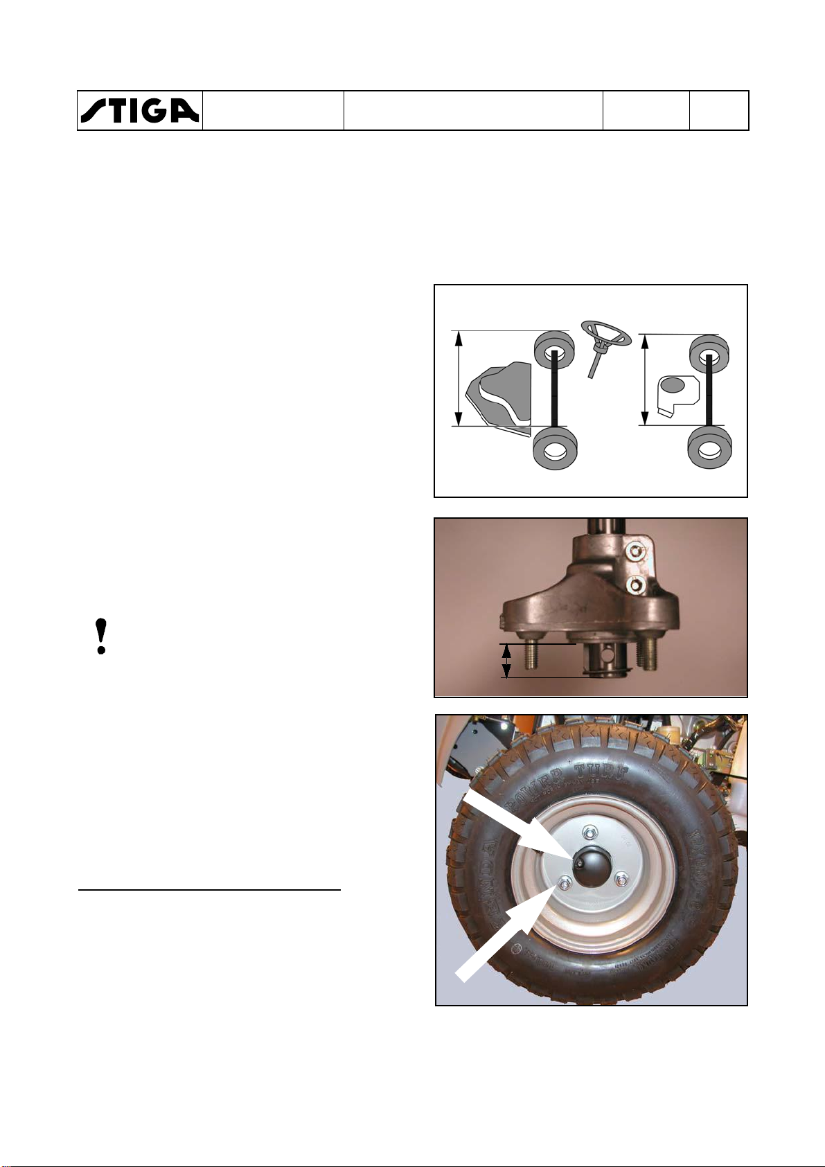
1. Push the hub on the shaft until it rests
2. Assemble the washer and the circlip onto the
3. Check the key and assemble it in the groove,
4. Assemble the rear wheel without tightening
5. Measure the distance (X) between the front
Assembly
against the transmission body.
shaft. The washer shall rest against the
circlip.
against the washer.
the nuts.
wheels and adjust the rear hubs until the
distance between the rear wheels is the
same (X).
Pull out the hubs until the measure (Y) is the
same at the both sides.
Note!
If the measures between the wheels front
and rear not is the same, the machine will
be hard to steer.
X
X
Y
6. Tighten the two allen screws, using a 8 mm
allen key.
The tightening shall be performed in two
steps. Tighten first to 18 Nm and then, finally
to a torque of 24 Nm.
7. Assemble the rear wheel and the protecting
cover.
Asembly when tyre chains are used
To give place for the tyre chains, the distance X
can be increased. If necessary until the hub
rests against the washer.
15/17 mm box spanner
Page 19
WORKSHOP MANUAL
PARK
2.2
Lubrication chassis
The bearing for the articulation must be
lubricated in accordance with the service
schedule. Other moving parts are lubricated
once per season, although at least every 50
operating hours.
Note!
Lubrication is equally important for a
machine that is only used for a few hours
per year.
Note!
The lubricant provides not only
protection from wear but also from rust.
Note!
The machine should always be
lubricated before prolonged storage.
The bearing for the articulation has four grease
nipples which must be lubricated with universal
grease.
The steering chain must be lubricated with
chain spray two or three times per season.
If the chains are heavily fouled: dismantle the
chains and wash them.
Refit and lubricate them.
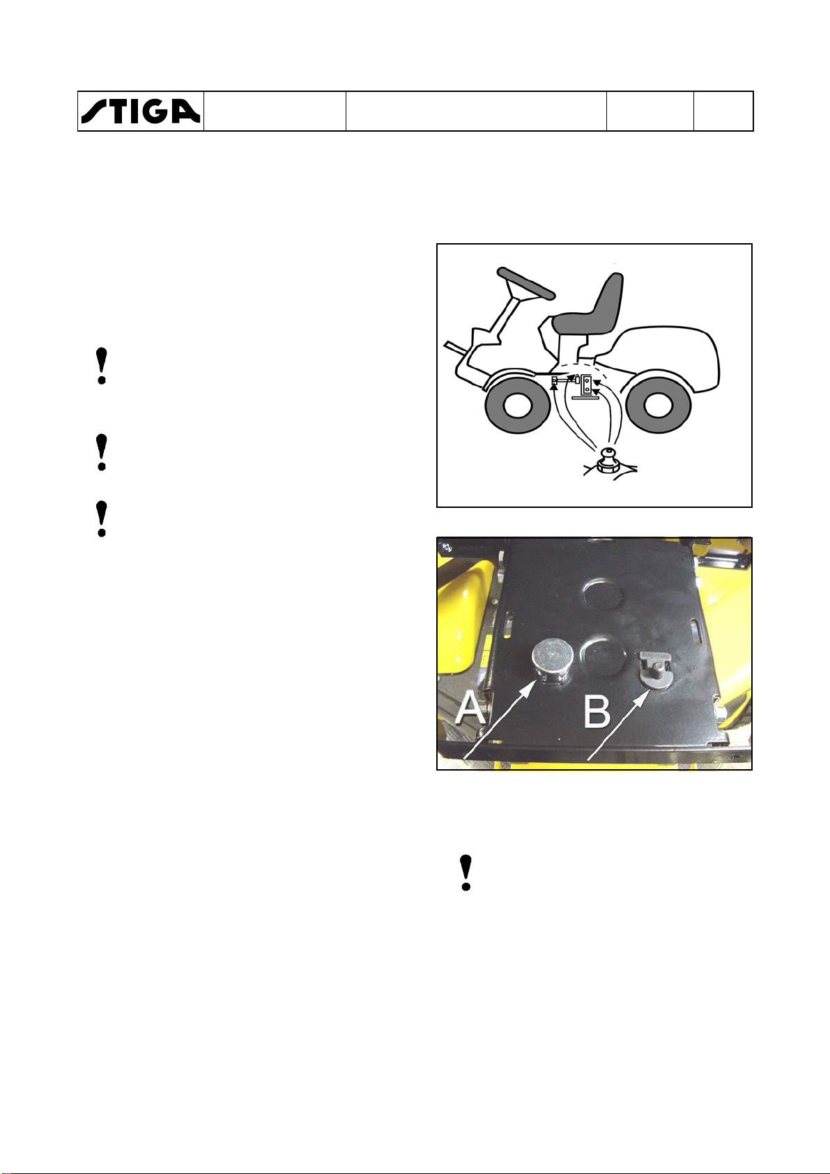
The pressure pin (A) in the seat suspension
must be lubricated to avoid problems with the
safety circuit.
Plastic bearings, e.g. the brake pedal bearing,
hydrogear pedal bearing and steering-column
bearing, must be lubricated with grease or
lubricating spray.
Drop a little engine oil or lubricating spray in the
ends of the control wires two or three times a
year.
Chapter
2 - Chassis and body
Note!
Wires on machines used in
freezing conditions should not be
lubricated with engine oil since
this can lead to the control cables
seizing in the cold.
The wires on such machines
should be lubricated with a
fluent, strongly penetrating
lubricant, e.g. 5-56 or WD40.
EDITION
2018
Page
3
Page 20
WORKSHOP MANUAL
PARK
2.3
Hydraulic pump
This section will describe the replacement
procedure for the external hydraulic pump in
4WD Park machines.
2.3.1
Dismantling
1. Remove the battery. See the owners
manual.
2. Block up the machine. Use a lifting table or
highjack and yokes.
3. Activate the parking brake.
4. Discharge the oil in the hydraulic system.
See the owners manual.
Chapter
2 - Chassis and body
EDITION
2018
Page
4
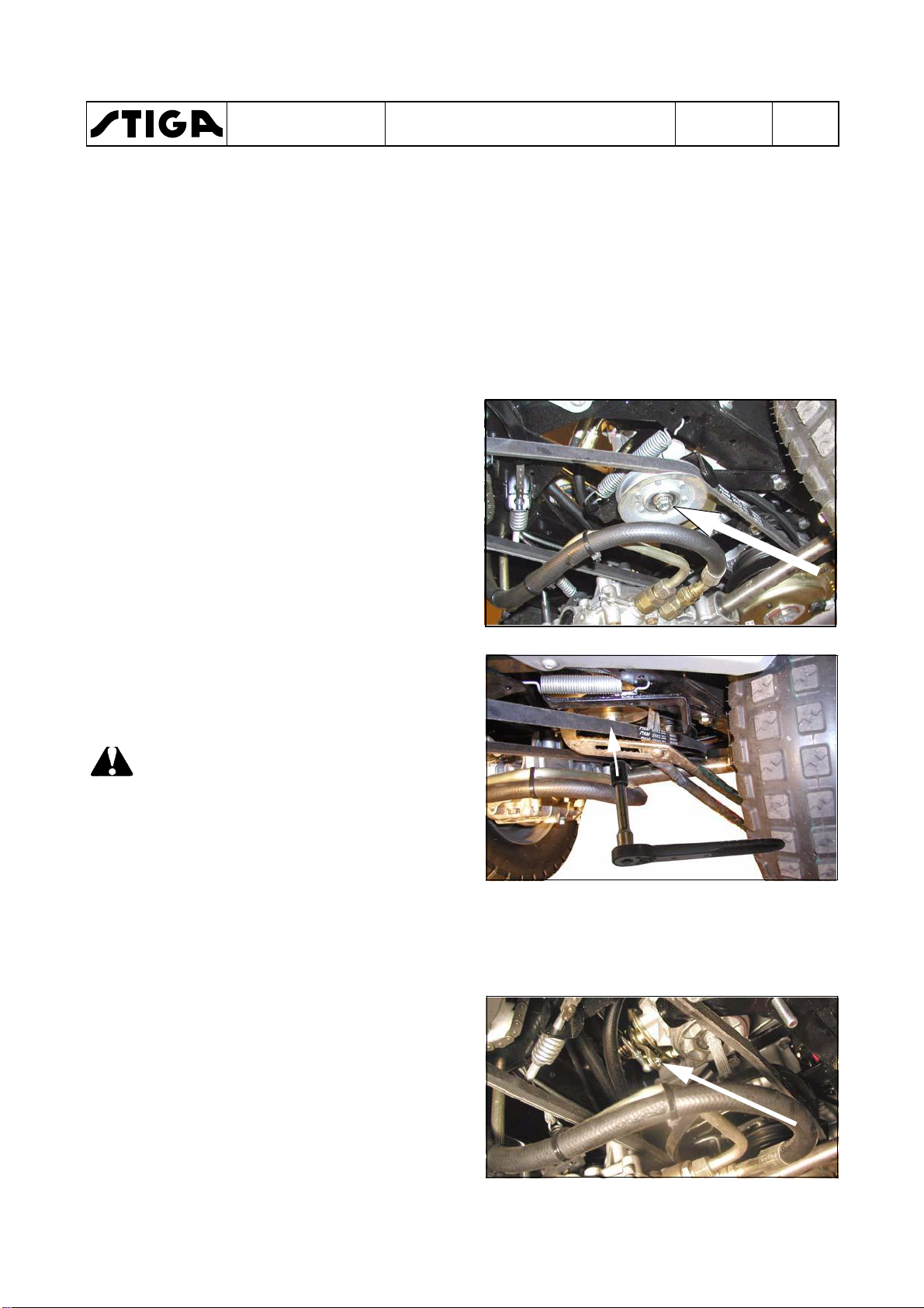
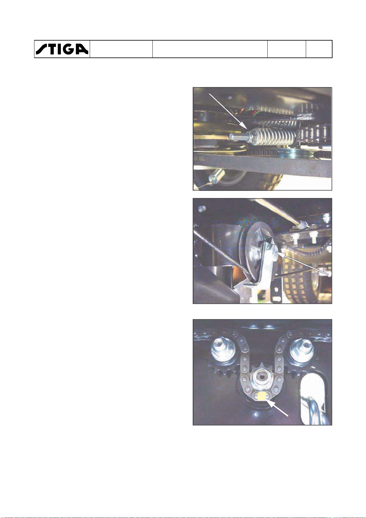
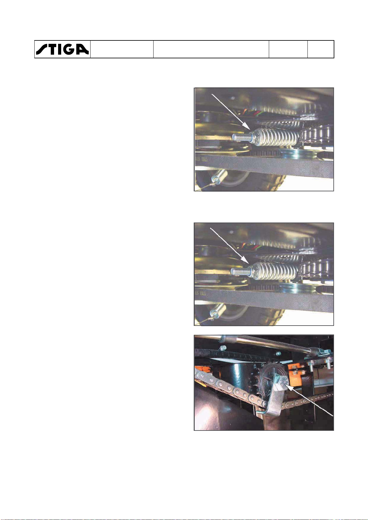
5. Remove the tension pulley by using a 15 mm
and a 17 mm spanner. See the figure.
6. Use a large polygrip and hold the pump
pulley in a securely grip. Fit the polygrip
around the belt, not direct to the pylley.
Back off the pulley nut with a 17 mm sleeve.
See the figure.
Warning!
Be carefully not to damage the
plastic fan during the removal.
7. Remove the following parts from the pump
shaft:
•
Nut
•
Washer
•
Pulley
•
Distance sleeve
•
Fan
•
Distance sleeve
8. Remove the speed control cable from the
hydraulic pump by backing off the nut. Use a
8 mm spanner. See the figure.
9. Back off the circlip from the release lever rod
and disconnect the rod from the lever.
Page 21
40 Nm
78 Nm
78 Nm
40 Nm
B
40 Nm
A
78 Nm
WORKSHOP MANUAL
PARK
10. Place a collecting tray under the pump for
collecting residual oil from the pump and
hoses.
Warning!
Do not spill any oil on the drive belts
during the disconnection of hoses
and tubes.
Warning!
Keep clean when handling hydraulic
parts. Dirt in the oil will cause
malfunctions and breakdowns.
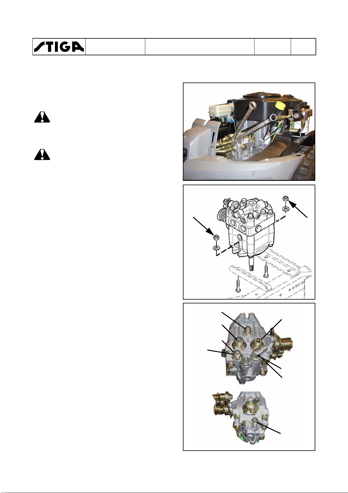
11. Disconnect all hoses and tubes from the
hydraulic pump. Always use two spanners,
one to hold the respective connection in the
pump and one to loosen the nut. See the
figure.
Chapter
2 - Chassis and body
EDITION
2018
Page
5
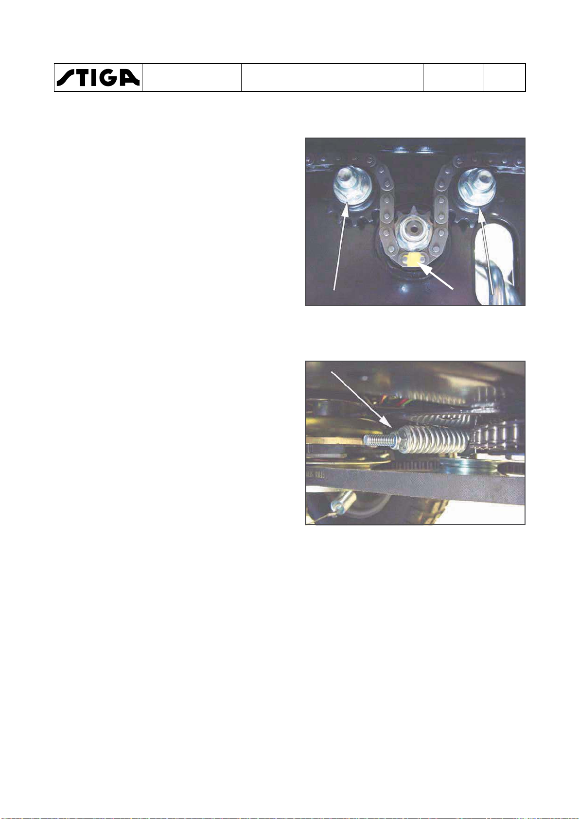
12. Remove the pump from the chassis by
unscrewing the two M10 mounting nuts and
screws. Use two 17 mm spanners. See the
figure.
13. Place and fasten the pump in a table vice.
Loosen the adapters from the pump.
14. Screw out the adapters and insert them in
the corresponding places in the new pump
one at a time. Check or replace the O-rings.
3. Place and fasten the new pump in a table
vice. Tighten the adapters to torques
according to the figures.
When tightening the angle adapter (A),
adjust it to 45° according to the horizontal
line. Use one 14 mm and one 19 mm
spanner.
If a metal tube shall be fitted to the adapters
A and B (machines without external
hydraulics), the connection nuts shall be
tightened with 41 Nm.
Page 22

WORKSHOP MANUAL
PARK
2 - Chassis and body
Chapter
EDITION
2018
Page
6
2.3.2
Assembly
Warning!
Keep clean when handling hydraulic
parts. Dirt in the oil will cause
malfunctions and breakdowns.
Warning!
Be carefully not to damage the
plastic fan during the assembly.
Assemble all parts in the reverse order.
Note!
One distance sleeve (C) at each side of
the fan.
Note!
The tension pulley (D) shall be fitted with
the prolonged part of the sleeve
upwards. See both figures.
C
C
D
Adjust the speed cable. See section 6.
When all parts are fitted and all actual
tightening torques are applied, fill new oil and
bleed the hydraulic system. See the owners
manual.
Up
D
Page 23

WORKSHOP MANUAL
PARK
3 Steering
Contents in this chapter
3.1 Description ....................................... 2
3.1.1 Mechanical system ........................ 2
3.1.2 Hydraulic assisted system ............. 2
3.2 Steering wires ................................... 4
3.2.1 Replacement ................................ 4
3.2.2 Adjustment .................................... 5
3.2.3 Steering chains .............................. 5
General
Chapter
3 - Steering
EDITION
2018
Page
1
3.3 Bearings, steering shaft .................. 7
3.3.1 Replacement of sliding bearings
and ball bearings .................................... 7
3.3.2 Replacement of upper ball bearing
(with steering booster) ............................ 8
3.3.3 Trouble shooting ............................ 9
The articulation steered machines are equipped with either a common mechanical system
or a hydraulic assisted steering system. Both systems work with wires or chains,
depending on the model. The hydraulic assisted system gets its power from the variable
hydraulic transmission at the rear shaft.
This chapter contains a brief description of the function and describes repair, replacements
and adjustments of stressed parts of the steering system.
Page 24
3.1
WORKSHOP MANUAL
PARK
Description
Chapter
3 - Steering
EDITION
2018
Page
2
3.1.1
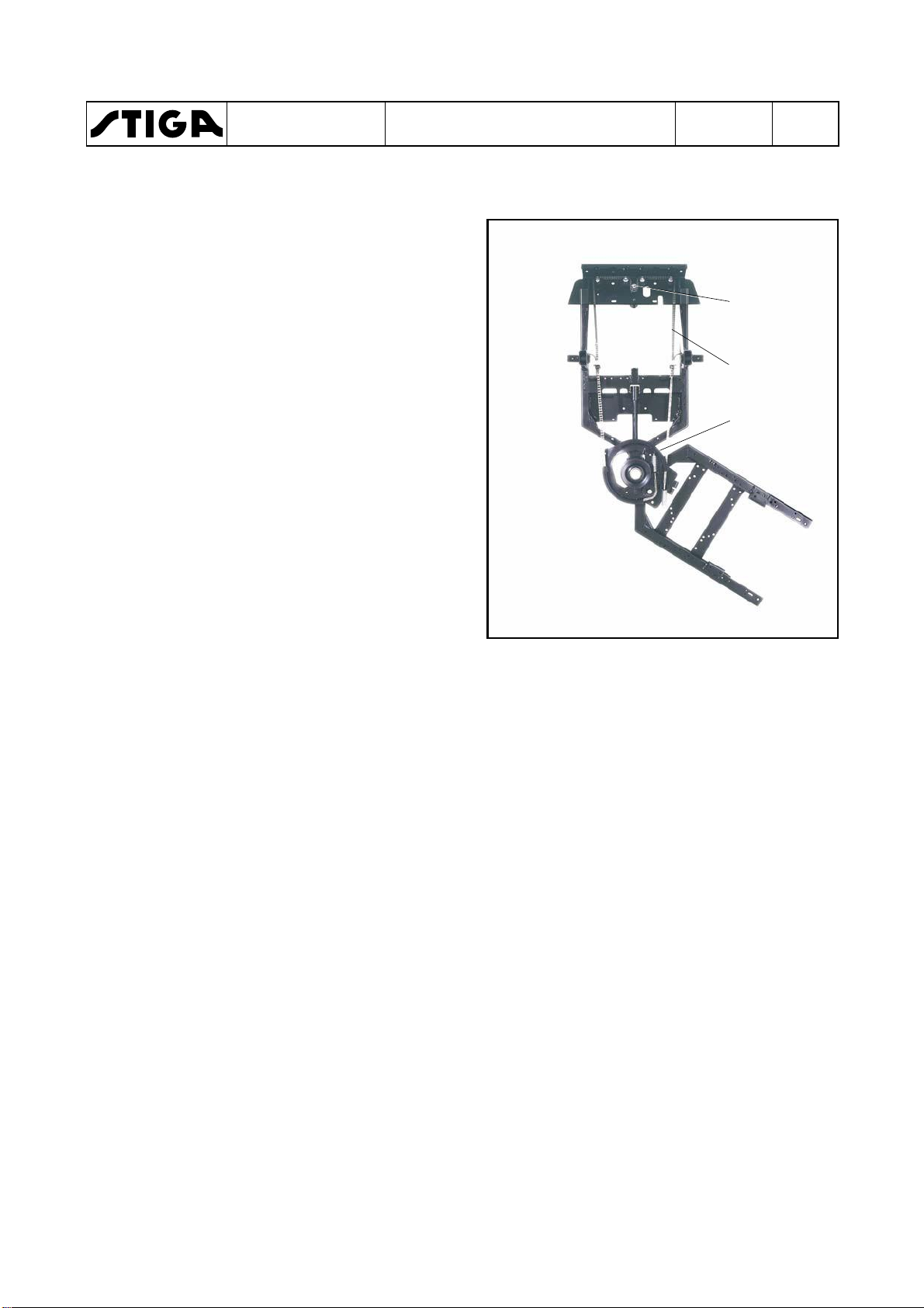
The sprocket (A) is directly coupled to the
stering wheel on the same shaft. A chain (and
wires) (B) is engaged with the sprocket and
connected to the steering disc (C) on the rear
frame. Thus, the rear frame is forced into actual
angles, related to the front frame when the
driver turns the steering wheel.
3.1.2
Below is given a brief description about how the
steering torque converter works and its
connection to the valves. For a complete
description, see section 4 “Hydraulic system”.
Section 4 describes how the lifting cylinder
works together with the steering torque
converter. It also describes the pressure
division between the two systems and
adjustments.
The power assisted steering is a hydraulic
auxiliary system. The main components are the
torque converter and the oil pump in the
hydrogear.
Mechanical system
Hydraulic assisted system
A
B
C
As opposed to standard power steering (e.g. in
a car), this power assisted steering has a
limited capacity. This implies that in certain
circumstances it has what may be experienced
as negative characteristics.
At low engine speed, or in situations where
extra steering power is required, the steering
may be considered to be somewhat jerky.
The machine should always be in motion when
the steering is used. Avoid turning the steering
wheel when the machine is standing completely
still and the accessory is in lowered working
position.
The machine can be steered even when the
engine is switched off. Nevertheless, it may
require more force than normal to steer the
Page 25
Md D
A
Ms
Mh
Md+Mh=Ms
35-42 Nm
35-42 Nm
30-37 Nm
WORKSHOP MANUAL
PARK
machine. This is particularly noticeable during
cold weather.
Mainly, the hydraulic assisted system works
similar to the mechanical system. The different
is a torque booster (D), atttached to the steering
shaft between the steering wheel and the
sprocket (A).
A oil flow from the HST is flowing through the
torque booster via a filter.
As the driver turns the steering wheel, there
occour a pressure drop over the torque booster.
The pressure drop, multiplied with the flow,
gives a moment (Ma), which is added to the
moment from the driver (Md) and applied on the
sprocket (A) as a moment (Ms).
Chapter
3 - Steering
EDITION
2018
Page
3
The following items are shown in the figure:
A Sprocket of driving the steering chain.
D Torque booster.
Mh Steering power (moment) from the
hydraulic transmision.
Md Hand power (moment) from the driver.
Ms The sum of Ma and Md as steering power
(moment on sprocket A).
Hydraul connections
The hydraul lines have two alternative
connections:
•
Pressure plate with O-rings around the tubes.
•
Banjo fitting.
Pressure plate
Always mount new O-rings when assembling.
Banjo fitting
The connection have no gaskets.
Always tighten the nipples with the correct
tightening when assembling. See the figure.
Page 26
WORKSHOP MANUAL
PARK
3.2 Steering wires
3.2.1 Replacement
1. Loosen the nuts on the steering wire. Brace
with a spanner so that the wire does not
rotate.
2. Loosen the screws that hold the pulley so
that the wire can be taken out between the
pulley and the wire retainer.
Chapter
3 - Steering
EDITION
2018
Page
4
3. Unhook the chain at the front chain sprockets.
It can sometimes be easier to get the chain
off by slightly unscrewing the screws that
hold the chain sprockets.
4. Measure up the middle link (mark A) on the
new chain and mark it.
5. Place the chain on the chain sprockets.
Make sure that the wheel is straight and that
the marked middle link is placed on the middle of the chain sprocket.
6. Place the wire in the pulley and tighten the
screws to the wire retainers.
7. Fit the washer and nut on the threaded rear
ends of the steering wire.
A
Page 27
WORKSHOP MANUAL
PARK
3.2.2 Adjustment
1. Tension the wire nuts equally on both sides
so that the wheel is straight when the
machine is straight.
Brace with a spanner so that the wire does
not twist.
2. Turn the wheels fully out in both directions.
Check that the chain does not go into the
pulley and that the wire does not go into the
chain sprocket.
3. Test drive. Check the tension of the wire
after test driving.
Chapter
3 - Steering
EDITION
2018
Page
5
3.2.3 Steering chains
1. Loosen the nuts on the steering chain.
2. Loosen the screws that hold the chain
sprockets so that the chain can be taken out
between the chain sprocket and wire
retainer.
3. Unhook the chain at the front chain
sprockets.
It can be easier to get the chain off by slightly
unscrewing the screws that hold the chain
sprockets.
Page 28
WORKSHOP MANUAL
PARK
4. Measure up the middle link (A) on the new
chain and mark it.
5. Place the chain on the chain sprockets.
Make sure that the wheel is straight and that
the marked middle link (A) is placed on the
middle of the chain sprocket.
6. Place the wire on the chain sprockets and
tighten the screws to the wire retainers.
7. Fit the washer and nut on the threaded rear
ends of the steering chain.
8. Adjust as described below.
Chapter
3 - Steering
EDITION
2018
A
Page
6
Adjustment
1. Tension the nuts equally on both sides so
that the wheel is straight when the machine
is straight.
2. Turn the wheels fully out in both directions.
Check that there is no abnormal noise or
abnormal resistance.
3. Test drive. Check the tension of the chain
after test driving.
Page 29
WORKSHOP MANUAL
PARK
3.3 Bearings, steering shaft
The steering shaft bearings are configurated in
one of the following three ways:
• Two sliding bearings of the composite type.
• Two sealed ball bearings.
• One sealed ball bearing (upper) and one ball
bearing in the torque booster (lower).
3.3.1 Replacement of sliding bearings
and ball bearings
1. Remove the chain from the lower sprocket.
See previous sections.
2. Tap out the spring pin that holds the steering
wheel. Remove the steering wheel.
Chapter
3 - Steering
EDITION
2018
Page
7
3. Pull up the parking brake knob, remove the
upper cover and the lamp section.
4. Remove the to screws, holding the steering
column and remove the steering column (A).
5. Tap out the bearings with a long drift, bar or
similar.
6. Tap in the new bearings with a rubber mallet.
A
7. Reassemble in the reverse order and adjust
the chain/wire. See previous sections.
Page 30

WORKSHOP MANUAL
PARK
3.3.2 Replacement of upper ball bear-
ing (with steering booster)
1. Tap out the spring pin that holds the steering
wheel. Remove the steering wheel.
2. Pull up the parking brake knob, remove the
upper cover and the lamp section.
Note!
Do not forget the washer (G).
The correct number of shims must be
used to avoid tensions in the steering
column.
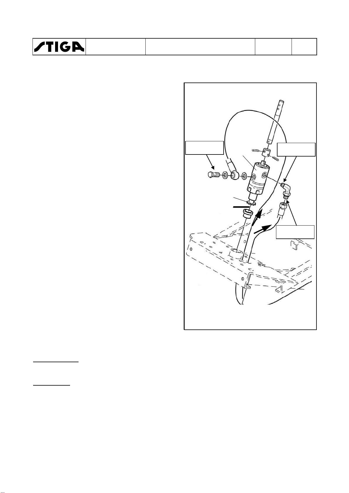
3. Remove the split pin from the hydraulic lift
bolt (A) and push out the bolt.
4. Remove the spring (B).
Chapter
3 - Steering
A
EDITION
2018
Page
8
5. Remove the four nuts (C) from the underside and the screw (E), holding the steering
console (F) and lift out the steering console
with its four screws.
6. Remove the three M8-screws (I) from the
lower steering tube (D) and pull up the
steering tube with the washer (G).
7. Press or knock out the ball bearing (H) from
the steering tube and assemble a new bearing with help of a rubber mallet.
8. The assembling is performed in the reverse
order.
Note!
Do not forget the washer (G).
The correct number of shims must be used
to avoid tensions in the steering column.
C
D
E
B
F
G
H
I
Page 31

WORKSHOP MANUAL
PARK
3.3.3 Trouble shooting
One prerequisite for the function of the power
assisted steering is the play in the steering. This
play must always spring back to the starting position when the wheel is released.
T est by slowly turning the wheel in one direction
when the engine is switched off. At first there is
a slight resistance, which increases when the
machine begins to turn. Release the wheel. It
should now return to the middle position.
The wheel should spring back approx. 10-20
mm when the wheel is released after turning.
However, the machine will not
“drive straight forward” after turning in the same
way as a car.
automatically
Chapter
3 - Steering
EDITION
2018
Page
9
If the machine always turns in the same direction as soon as the engine is started, there is
probably a fault in the torque converter.
Another conceivable fault can be that the bearing in the steering column tube is jamming, so
that the steering wheel cannot automatically return to the neutral position.
Note!
If the steering does not function this does
not mean that there is always a fault in the
torque converter. Faults can also occur in
more simple mechanical parts such as
chains and gear wheels.
Page 32

WORKSHOP MANUAL
PARK
4 Hydraulic system
Contents in this chapter
Chapter
4 - Hydraulic system
EDITION
2018
Page
1
4.1 Safety ................................................. 2
4.2 Configuration .................................... 2
4.2.1 Hydraulic diagram (Version 2019 -
with lift) ................................................... 5
4.2.2 Hydraulic diagram (Version 2019 -
without lift) .............................................. 6
4.3 Hydraulic pump integrated in the
rear axle drive ....................................... 7
4.3.1 Physical description ....................... 7
4.3.2 Functional description ................... 8
4.4 Separate hydraulic pump for the
power transmission .............................11
4.4.1 Physical description ..................... 11
4.4.2 Functional description ................. 12
4.5 Hydraulic assisted steering and im-
plement lifter ......................................... 15
4.5.1 Physical description ..................... 15
4.5.2 Functional description ................. 16
4.6 Hydraulic assisted steering .......... 21
4.6.1 Physical description ..................... 21
4.6.2 Functional description ................. 21
4.7 Trouble shooting ............................. 22
4.7.1 Drive system ................................ 22
4.8 External hydraulic .......................... 24
4.9 Change of trans oil, 4WD ............... 27
4.9.1 Transmission with external pump . 27
4.9.2 Transmission with the hydraulic
pump in the rear axle drive ................... 30
General
The four wheel drive Park machines are equipped with hydraulic power transmission. I.e.
the engine drives an hydraulic pump, which pumps oil through the rear and front axle
drives. There are two main configurations; separate hydraulic pump and the hydraulic
pump integrated in the rear axle drive.
The front axle and rear axle are connected in series, which means that the front wheels
and rear wheels are forced to rotate at the same speed. To make turning easier, both axles
are equipped with a differential.
Some of the machines, both 2WD and 4WD, are also equipped with hydraulic assisted
steering and implement lifter.
Front-mounted implements are powered via drive belts.
This chapter contains a description of the hydraulic system, trouble shooting to isolate
faults and information about adjustments and corrective measures.
Since the steering torque converter and lifting cylinder belong to the respective chapter
(2 and 3), these components are described in detail in these chapters.
Page 33

Hydraulic
pump
See
Separate
hydraulic
pump See
See
See
Hydraulic
implement
fter
See
13-6002-XX
Mountfield 4140H
X
X
13-6003-XX
Mountfield 4155H
X
X
13-6004-XX
Mountfield 4155H 4WD
X X
13-6100-XX
Park Silent
X
X
13-6101-19
Park Compact 13
Manual gear 5-speed
13-6102-XX
Park Compact 14
X
X
13-6103-XX
Park Compact 16
X
X
13-6104-XX
Park Compact 16 4WD
X X
13-6105-99
Mountfield XK 13
Manual gear 5-speed
13-6106-99
Mountfield XK 16
X
X
13-6107-99
Mountfield XK 16 4WD
X X
13-6109-XX
Park Compact 14
X
X
WORKSHOP MANUAL
PARK
4 - Hydraulic system
Chapter
EDITION
2018
Page
2
4.1
Safety
Hydraulic oil under pressure can be very dangerous if hoses, lines or other
distribution parts are leaking. To avoid personal injuríes, always wear protection
gloves and protection goggles during works with the hydraulic system.
Before starting the motor, place the machine outdoors or install an extraction device
for the exhaust fumes. Otherwise the personel will be poisoned.
Cleanliness is mandatory at all works with the hydraulic system. Foreign substances
and contaminations will jeopardize the function and reliability of the system. Always
protect and close openings of hoses, lines and connections when replacing components.
4.2
Configuration
The machines are equipped with systems according to the table below:
Art.
Number
Machine
Castelgarden XK 140 HD
Béal Master MBF 13,5
Mountfield 4135H
Castelgarden XK 160 HD
Béal Master MBF 15,5
Mountfield 4155H
Castelgarden XK4 160 HD
Béal Master MBF 15,5
Mountfield 4155H 4WD
5
drive
drive
Wheel
2
drive
Wheel
4
axle
rear
the
in
page
at
"4.3"
8
page
at
"4.4"
4WD
steering,
Hydraulic
11
page
at
""
2WD
steering,
Hydraulic
18
page
at
"4.6"
11
page
at
""
li
Page 34

Hydraulic
pump
See
Separate
hydraulic
pump See
See
Hydraulic
implement
lifter
13-6111-61
OKAY Mcut 98-10/155 K4WD
X X
13-6116-XX
Castelgarden XK 140 HD
X
X
13-6141-XX
Park Unlimited 14
X
X
13-6142-XX
Park Unlimited Plus
X
X
13-6144-XX
Park Silent
X
X
13-6175-26
Park Power 4WD
X X
13-6176-16
Park Champion
X
X
13-6177-XX
Park Prestige 4WD
X X
13-6178-15
Park Residence 4WD
X X
X
13-6178-16
Park Residence 4WD
X X
X
13-6179-04
Park Ranger
X
X
X
13-6179-05
Park Ranger Svan
X
X
X
13-6179-06
Park Ranger Svan
X
X
X
13-6180-XX
Park Diesel
X
X
13-6181-34
Park Diesel 4WD
X X
X
X
13-6182-14
Park Comfort
X
X
13-6182-15
Park Comfort
X
X
13-6183-14
Park Royal
X
X
13-6184-XX
Park President 14
X
X
13-6185-XX
Park Prestige 4WD
X X
13-6189-XX
Park Excellent 16
X
X
13-6193-XX
Park Ranger
X
X
X
13-6195-14
Park Fairway 18
X
X
13-6196-25
Park Power 4WD
X X
13-6197-XX
Castelgarden XKH4 165 HD
X X
13-6198-55
75 Years ltd version
X
X
13-6199-15
Park Residence 4WD
X X
X
13-6241-XX
Park Pro 16 4WD
X
X
13-6241-XX
Park Pro Svan 4WD
X
X X
X
13-6242-64
Park Pro Bivoj 4WD
X
X
13-6244-XX
Park Pro 20 4WD
X
X X
X
13-6246-XX
Park Pro 25 4WD
X
X X
X
Art.
Number
WORKSHOP MANUAL
PARK
Machine
Chapter
4 - Hydraulic system
5
drive
drive
Wheel
2
drive
Wheel
4
axle
rear
the
in
page
at
"4.3"
8
page
at
"4.4"
4WD
steering,
Hydraulic
11
page
at
""
See
EDITION
2018
2WD
steering,
Hydraulic
18
page
at
"4.6"
Page
3
11
page
at
""
See
Page 35

Hydraulic
pump
See
Separate
hydraulic
pump See
See
Hydraulic
implement
lifter
13-6269-XX
Park Pro 18 4WD
X
X X
X
13-6270-XX
Park Pro 21 4WD
X
X X
X
13-6271-XX
Park Pro 16 4WD
X
X X
13-6272-XX
Park Pro Svan 4WD
X
X X
X
13-6273-XX
Park Pro 20 4WD
X
X X
X
13-6274-16
Park Pro 23 4WD
X
X X
X
13-6275-16
Park Pro Silver
X
X
13-6276-XX
Park Pro 25 4WD
X
X X
X
13-6310-XX
Park Excellent 16, 620 W
X
X
13-6311-XX
Park Plus
X
X
13-6312-XX
Park Royal 4WD
X X
X
13-6313-11
Park Excellent
X
X
13-6314-11
Park Plus Unlimited
X
X
13-6317-32
Park 740 PWX
X X
X
13-6318-31
Park 520 DP
X
X
X
13-6319-31
Park 520 DPX
X X
X
13-6320-11
Park 520 Anniversary
X
X
X
13-6372-11
Park Power 16 4WD
X X
13-6373-XX
Park 740 WX, Park Ro. 4WD
X X
X
13-6374-11
Park Champion 4WD
X X
X
13-6375-11
Park Power 4WD
X X
13-6377-11
Park Prestige 4WD
X X
13-6378-XX
Park Residence 4WD
X X
X
13-6379-XX
Park Ranger Svan
X
X
X
13-6380-XX
Park 620 PW
X
X
X
13-6381-XX
Park 540 LPX
X X
X
13-6384-11
Park 123
X
X
13-6384-12
Park 420 LM
X
X
WORKSHOP MANUAL
PARK
4 - Hydraulic system
Chapter
EDITION
2018
Page
4
Art.
Number
Machine
drive
Wheel
2
drive
Wheel
4
drive
axle
rear
the
in
5
page
at
"4.3"
8
page
at
"4.4"
4WD
steering,
Hydraulic
11
page
at
""
See
2WD
steering,
Hydraulic
18
page
at
"4.6"
11
page
at
""
See
The power transmission and the hydraulic assisted steering and implement lifter work with
the same oil, but in two separate parallel systems. Therefore, the descriptions are divided
in the following headings:
The following sections will explane the physical arrangement of the hydraulic components
and give a functional description.
Page 36

WORKSHOP MANUAL
PARK
4 - Hydraulic system
Chapter
4.2.1 Hydraulic diagram (Version 2019 - with lift)
EDITION
2018
Page
5
Page 37

WORKSHOP MANUAL
PARK
4 - Hydraulic system
Chapter
4.2.2 Hydraulic diagram (Version 2019 - without lift)
EDITION
2018
Page
6
Page 38

4 11
12
6
10 9 8 7 2
3
5
B
1
A
13
4.3
WORKSHOP MANUAL
PARK
4 - Hydraulic system
Chapter
EDITION
2018
Hydraulic pump integrated in the rear axle drive
Page
7
4.3.1
A. Rear axle drive.
1.
2.
3.
4.
5.
6.
Physical description
The parts 1-3 and 5-8 below are built
in the rear axle drive.
Charge pump, 35-45 bar.
Main pump.
Pressure limit valve for the charge
pressure.
Oil container.
Oil filter.
Connection to the external hydraulics
(steering converter and implement
lifter).
B. Front axle drive. The parts 9 and 10
below are built in the front axle drive.
9.
Hydraulic motor, front axle.
10.
By-pass valve, front axle.
11.
Leak flow line.
12.
Main flow line.
13.
Main flow line.
Colour - Pressure
Red is the feeding pressure to the
main pump and to the external
hudraulics.
7.
Hydraulic motor, rear axle.
8.
By-pass valve, rear axle.
Dark red is the working pressure
to the hydraulic motors.
Blue is the atmospheric pressure
in the oil container and housings.
Light blue is below the
atmospheric pressure (pump
suction side).
Page 39

Driving forward - Integrated pump
11
4
12
6
10
8
9 7
2
3
5 B
1
A
13
Driving backward - Integrated pump
4 11
12 6
10
9 8 7
2
3
5 B 1 A
13
WORKSHOP MANUAL
PARK
4 - Hydraulic system
Chapter
EDITION
2018
Page
8
4.3.2
Functional description
Driving
The oil flows when driving forwards respectively backwards are showh in the diagrams
below.
117
146
Page 40

WORKSHOP MANUAL
PARK
4 - Hydraulic system
Chapter
EDITION
2018
Page
9
The engine drives the charge pump (1) and the main pump (2) with a constant speed. The
charge pump is feeding the main pump. The oil, fed into the main pump during operation, is
a replacement for the leak oil from the front and rear axle drives (A and B).
The charge pump sucs its oil from the rear axle drive volume and through the lter (5). The
rear axle drive is supplied with oil from the oil container (4).
The oil ow and the ow direction through the main pump (2) - front hydraulic motor (9)
- rear hydraulic motor (7) is controlled by the speed pedal, mechanical connected to the
main pump (2) in the rear axle drive (A). The main pump pressure is depending on the
power requirements at the wheel axles and is limited by the engine power.
The motors are connected in serie with the front motor (9) rst, when driving forwards.
This means, due to the leakage in the front motor, that the machine under normal conditions drives on the front wheels only. When the front wheels begin to slip (rotate with 1-4%
higher speed than the rear wheels) also the rear wheels start to drive and the slipping is
avoided.
This fact is not noticed by the operator, since the machine is driven with its four wheels
after demand.
Dynamic balancing valve.
The hydraulic circuit is equipped with a dynamic balancing valve for the correct balancing
of the circuit. When the machine is stationary, the dynamic balancing valve is open and allows the hydraulic steering to rotate smoothly.
While when the machine starts to move forward, the dynamic balancing valve closes automatically, the front drive axle starts to transmit and then a few moments later, the rear drive
axle also starts to transmit. The rotation of the hydraulic steering remains uid.
The time that passes between the engagement of the front axle and the rear axle is not
normally perceived by the user.
Page 41

WORKSHOP MANUAL
PARK
Chapter
EDITION
4 - Hydraulic system
The dynamic balancing valve
has a standard calibration of
0.15mm, this can be adjusted
in the +/- 0.05 range compared to the standard calibration.
With a dynamic balancing
valve set to 0.10mm, the
valve closing time will be
reduced.
With a dynamic balancing valve set to
0.20mm, the valve closing time will be
increased.
2018
Page
10
By-pass valves
The axle drives are equipped with by-pass valves. Each by-pass valve is connected to their
clutch release lever
. When the by-pass valve (10) is open, it allows oil to ow into the motor
housing and the pressure drop
over the motor is such neutralized. The bypass valve is intended to make it possible to
push the machine without heavy resistance from the axle drive.
The front by-pass valve is equipped with a mechanic interlock which always resets the valve, if
previously opened, at driving attempts forwards
An attempted to drive the machine forwards with
the rear by-pass valve (8) closed and the front
by-pass valve (10) open will result in an powerful oil ow into the front axle drive housing. Since
the leak ow line (11) not are dimensioned for this
ow and the main ow line (13) is blocked, it will
result in a hazardous pressure rise in the front
axle drive housing. This pressure rise forces the
oil to presses out through the sealings and can
cause damages.
8. Rear clutch release lever, connected
to the rear bypass valve.
10. Front clutch release lever, connected
to the front bypass valve.
Page 42

4 11 5
11
11
12
6 13
B 3
A
9
8
C
2
7 1 3 12
WORKSHOP MANUAL
PARK
4.4
Separate hydraulic pump for the power transmission
4 - Hydraulic system
Chapter
EDITION
2018
Page
11
4.4.1
Physical description
A. Rear axle drive with its hydraulic
motor (7).
B. Front axle drive with its hydraulic
motor (9).
C. Hydraulic pump. The parts 1-3 and 8
below are built in the hydraulic pump.
1.
Charge pump, 35-45 bar.
2.
Main pump.
3.
Pressure limit valve for the charge
pressure.
4.
Oil container.
13
8.
By-pass valve in the main pump (C).
9.
Hydraulic motor in the
front axle drive (B).
11.
Leak flow lines.
12.
Main flow lines.
13.
B-pass valve (only used when oil
change)
Colour - Pressure
Red is the feeding pressure to the
main pump and to the external
hudraulics.
5.
Oil filter.
6.
Connection to the external hydraulics
Dark red is the working pressure
to the hydraulic motors.
(steering converter and implement
lifter).
Blue is the atmospheric pressure
in the oil container and housings.
7.
Hydraulic motor in the
rear axle drive (A).
Light blue is below the
atmospheric pressure (pump
suction side).
Page 43

Driving forward - Separate pump
4 11 5
11
11
12
6
13 B 3
A 13 9
8
C
2
7 1 12
Driving backward - Separate pump
4
11
5
11
11
12 6
13 B 3
13
9 9
8
C 2
7 2
1 12
WORKSHOP MANUAL
PARK
4 - Hydraulic system
Chapter
EDITION
2018
Page
12
4.4.2
Functional description
Driving
The oil flows when driving forwards respectively backwards are showh in the diagrams
below.
Page 44

WORKSHOP MANUAL
PARK
The charge pump (1) and the main pump (2) are integrated into one unit, the hydraulic
pump (C) which is located separat in front of the engine.
The engine drives the the hydraulic pump (C) with a constant speed. The charge pump (1)
is feeding the main pump (2) with 35-45 bar. The oil, fed into the main pump during
operation, is a replacement for the leak oil from the front and rear axle drives (A and B) and
the main pump (2).
The charge pump sucs its oil from the oil container (4) and through the filter (5).
The oil flow and the flow direction through the main pump (2) - front hydraulic motor (9) rear hydraulic motor (7) is controlled by the speed pedal, mechanical connected to the
main pump (2). The main pump pressure is depending on the power requirements at the
wheel axles and is limited by the engine power.
The hydraulic motors and the hydraulic pump have a small oil leakage (1-4%), which
increases with increased power requirement (increased pressure). The leakage oil is
collected inside the unit housings an forwarded back to the oil tank through the leak flow
lines.
4 - Hydraulic system
Chapter
EDITION
2018
Page
13
The motors are connected in serie with the rear hydraulic motor (7) first, when driving
forwards. This means, due to the leakage in the rear motor, that the machine under normal
conditions drives on the rear wheels only. When the rear wheels begin to slip (rotate with
1-4% higher speed than the front wheels) also the front wheels start to drive and the
slipping is avoided. This fact is not noticed by the operator, since the machine is driven with
its four wheels after demand.
By-pass valve
The main pump (2) is equipped with a bypass valve (8), connected to its clutch
release lever. When the by-pass valve is
open, the main pump is disconnected from
the oil circuit by an open passage out into
the housing.
The pressure drop over the pump is such
neutralized and the oil can flush free in the
system. See the figure.
The by-pass valve is intended to make it
possible to push the machine without heavy
resistance from the main pump.
8
8
2
Page 45

figures.
With external hydraulic
6
6 5 2 7
4
3
1
Without external hydraulic
6
6
5
2
1.5-2.5 bar
7
4
35
3
1
WORKSHOP MANUAL
PARK
4 - Hydraulic system
Charge pump
The charge pump has two tasks:
•
To feed the external hydraulic with 35-45 bar.
•
To feed the main pump with its initial pressure, 1,5-2,5 bar.
External hydraulic
The charge pump (1) sucks oil from the oil
container (5).
When the external hydraulics are in use, the
pressure in the out line (3) is limited to 35-45
bar by the pressure valve (4).
Without external hydraulic
The connections for the external hydraulics are
connected to each other. Compare the two
Chapter
EDITION
2018
Page
14
The charge pump (1) sucs oil from the oil
container (5).
The pressure valve (4) has no function because
the pressure valve (7) is set to a much lower
pressure (see below).
Feeding the main pump
The line (2) feeds oil to the main pump
respective suction lines (depending on driving
forwards or backwards) through the respective
back valves (6). The pressure in the line (2) is
limited to 1,5-2,5 bar by the pressure valve (7).
-45 bar
7
4
Page 46

WORKSHOP MANUAL
PARK
4 - Hydraulic system
Chapter
4.5
Hydraulic assisted steering and implement lifter
This section is valid for 4WD machines with steering chain.
EDITION
2018
Page
15
4.5.1
This section explanes the physical arrangement of the hydraulic components and the
different maximal pressures in the system.
Physical description
A. The dashed box indicates parts (1-4)
which are builtin the rear axle drive or
arranged separat in front of the
engine.
B. Hand operated valve unit with the
built in parts 6-10.
1.
Charge pump.
2.
Main pump. This pump belongs to the
driving system and supplies the oil
pressure/flow.
3.
Pressure limit valve.
A
9.
Slide with 4 different hole patterns for
the resp. functions. Illustrated in
normal status.
10.
Hand lever, connected to the slide.
11.
Double acting lifting cylinder.
Red lines indicate the maximum total
pressure from the HST when the torque
converter (5) works.
Yellow lines indicate the maximum
pressure to the lifting cylinder when it lifts
the implement.
4.
Oil container.
5.
Steering torque converter.
Blue lines indicate return oil with low
pressure (>1 bar).
6.
Pressure limit valve.
7.
Pressure adjustment screw.
8.
Non-return valve.
Page 47

WORKSHOP MANUAL
PARK
4 - Hydraulic system
Chapter
EDITION
2018
Page
16
4.5.2
Functional description
Normal condition
Operation state:
•
Motor is running in full speed.
•
The steering wheel is not actuated.
•
The implement lifter is not activated.
The loading pump (1) is forcing oil through the steering converter (5), and the open valve
(9).
The oil flow is indicated with arrows in the figure below. Since neither of the two items are
working, the resistance can be ignored and the pressure is very low (<1 bar).
In the normal condition, the lifting cylinder (11) is locked in its set position, because no oil
can flow out or in since the oil lines are shut by the slide (9).
Page 48

WORKSHOP MANUAL
PARK
4 - Hydraulic system
Chapter
EDITION
2018
Page
17
Steering wheel actuated
Operation state:
•
Motor is running in full speed.
•
The steering wheel is actuated.
•
The implement lifter is not activated.
The loading pump (1) is forcing oil through the steering converter (5), and the open valve
(9).
The oil flow is indicated with arrows in the figure below. Since the steering converter (5) is
working, a pressure drop will be built up over it.
The pressure drop =
the pressure in the red line - the pressure after the steering converter (5)
The pressure drop is depending on the steering power needed and is limited of the built in
valve (3).
Page 49

WORKSHOP MANUAL
PARK
4 - Hydraulic system
Chapter
EDITION
2018
Page
Raising
Operation state:
•
Motor is running in full speed.
•
The steering wheel is actuated or not.
•
The implement lifter is activated upwards.
The operator has actuated the hand lever (10) to its raising position (rear position), which
moves the slide (9) to change the hole pattern between the connections in the valve. The
hole pattern is adapted for the raising procedure. Oil forces through the non-return valve
(8), through the slide (9) and presses out the piston in hydraulic cylinder (11).
When the piston in cylinder (11) is fully extended and the hand lever still is activated, the
oil will flow only through the valve (6) and a noice will be heard from the valve.
When the hand lever is released, valve (9) will reurn to its neutral position and the system
switches over to its normal state. The piston in the hydraulic cylinder (11) is then locked in
its actual position.
18
Page 50

WORKSHOP MANUAL
PARK
4 - Hydraulic system
Chapter
EDITION
2018
Page
Lowering
Operation state:
•
Motor is running in full speed.
•
The steering wheel is actuated or not.
•
The implement lifter lever is activated upwards.
The operator has actuated the hand lever (10) to its lowering position (one step forwards),
which moves the slide (9) to change the hole pattern between the connections in the valve.
The hole pattern is adapted for the lowering procedure (crossed in the figure below). Oil
forces through the non-return valve (8), through the slide (9) and presses back the piston
into the hydraulic cylinder (11).
In this arrangement, the implement is forced down, irrespective its weight.
When the piston in cylinder (11) has reached its bottom position and the hand lever still is
activated, the oil will flow only through the valve (6) and a noice will be heard from the valve.
When the hand lever is released, valve (9) will reurn to its normal position and the system
switches over to its normal state. The piston in the hydraulic cylinder (11) is then locked in
its actual position.
19
Page 51

WORKSHOP MANUAL
PARK
4 - Hydraulic system
Chapter
EDITION
2018
Page
Floating position
Operation state:
•
Motor is not running or is running in full speed.
•
The steering wheel is actuated or not.
•
The implement lifter is in its upper position.
The operator has actuated the hand lever (10), to its floating position (locked in front
position) which moves the slide (9) to change the hole pattern between the connections in
the valve. The hole pattern is adapted for the floating status. Both sides of the lifting cylinder
(11) is connected to each other and to the return line in the slide (9). I.e. no pressure can
reach any side of the cylinder. No oil pressure affects the cylinder. The main part of the oil
is flowing between the upper part and the lower part of the cylinder. A smaller part is flowing
between the oil container (4) and the cylinder due to the displacement of the piston rod. See
the arrows in the picture below.
In the floating position, the implement always rests against the ground with the same force
(the weight of the implement) and follows the contours of the ground.
20
Page 52

WORKSHOP MANUAL
PARK
4.6
Hydraulic assisted steering
This section is valid for 2WD machines
(e.g. Park Ranger Svan).
Chapter
4 - Hydraulic system
EDITION
2018
Page
21
4.6.1
This section explanes the physical
arrangement of the hydraulic components and
the different pressures in the system.
A. The dashed box indicates parts (1-4)
1.
2.
3.
4.
Red lines indicate the maximum total pressure
from the HST.
Blue lines indicate return oil with low pressure
(<1 bar).
4.6.2
Steering wheel actuated
Physical description
which are builtin the rear axle drive.
Charge pump.
Main pump. This pump belongs to the
driving system and supplies the oil
pressure/flow.
Pressure limit valve.
Oil container.
Functional description
Operation state:
•
Motor is running in full speed.
•
The steering wheel is actuated.
The loading pump (1) is forcing oil through the
steering converter (5).
The oil flow is indicated with arrows in the figure
below. Since the steering converter (5) is
working, a pressure drop will be built up over it.
The pressure drop =
the pressure in the red line - the pressure after
the steering converter (5)
The pressure drop is depending on the steering
power needed and is limited of the built in valve
(3).
Page 53

WORKSHOP MANUAL
PARK
4.7 Trouble shooting
Warning!
Hydraulic oil under pressure can be
very dangerous if hoses, lines or other distribution parts are leaking. To
avoid personal injuríes, always wear
protection gloves and protection
goggles during works with the hydraulic system.
4.7.1 Drive system
Before the trouble shooting takes place, it is
provided that the following states are fulfilled:
•
Machines with external pump; the axle bypass valves are in drive position. See the figure..
•
The clutch release lever (levers) shall be in
the drive position. See the figures.
•
Oil level in the oil container as desired.
•
No air in the hydraulic oil.
Chapter
4 - Hydraulic system
4 WD machines, internal pump
Clutch release lever, 2WD
EDITION
2018
Page
22
Clutch release lever, 4WD, int. pump
Clutch release lever, 4WD, ext. pump
Page 54

Symptom
Valid for
Fault
Measure
The machine drives
Machines with
Front by-pass valve
Close the by-pass
forwards but not
separate hydraulic
open.
valve.
backwards.
pump.
Big leakage in the front
Replace the front axle
axle drive.
drive.
The machine drives
Machines with
Rear by-pass valve
Close the by-pass
backwards but not
separate hydraulic
open.
valve.
forwards.
pump.
Big leakage in the rear
Replace the rear axle
axle drive.
drive.
Reduced speed
Machines with
Speed control cable
Adjust the cable
forwards and
separate hydraulic
housing is moved.
housing.
possibly faster
pump.
backwards.
Reduced speed and
All machines.
The suction filter (5) is
Clean the filter.
The front wheels
All machines.
One of the axle keys is
Replace the actual key.
The rear wheels
All machines.
One of the axle keys is
Replace the actual key.
Reduced or no
Machines with
The belt between motor
Worn belt
speed.
separate hydraulic
and pump is slipping.
Replace the belt.
pump.
Check if the fan and
Big leakage in the
Replace the external
The charge pump
Replace the external
The pressure limit valve
Check the valve and its
Machines with
The belt between motor
Worn belt
integrated hydraulic
and pump is slipping.
Replace the belt.
pump.
Check if the fan and
Big leakage in the rear
Replace the rear axle
All machines.
Speed control cable
Repair/adjust the speed
WORKSHOP MANUAL
PARK
4 - Hydraulic system
Chapter
EDITION
2018
Page
23
uneven drive.
don´t drive.
don´t drive.
clogged.
broken.
broken.
pulley at the pump
rotate.
external pump.
defective.
(1,5-2,5 bar) for the
charge pump defective.
pulley at the pump
rotate.
Maladjusted clutch wire
Adjust the wire.
pump.
pump.
spring. See “"" at page
11” at page 11.
Maladjusted clutch wire
Adjust the wire.
axle drive.
loose or mowed.
drive.
control cable.
Page 55

WORKSHOP MANUAL
PARK
4 - Hydraulic system
Chapter
EDITION
2018
4.8
External hydraulic
Warning!
Hydraulic oil under pressure can be very dangerous if hoses, lines or other
distribution parts are leaking. To avoid personal injuríes, always wear
protection gloves and protection goggles during works with the hydraulic
system.
Warning!
Before starting the motor, place the machine outdoors or install an extraction
device for the exhaust fumes. Otherwise the personel will be poisoned.
This section describes the trouble shooting procedures in absence of proper functions at
the hydraulic assisted steering and implement lifter. It also describes the correction
measures in each actual case. When following the trouble shooting table, it is provided that
the following states are fulfilled:
•
Parking brake not activated.
•
A new filter installed
•
Motor is running in full speed.
•
The oil reservoir level shall be adjusted.
•
The machine is warmed up during at least 10 minutes to a oil temperature of at least
50°C.
Page
24
The pressure (about 35 bar) in the external hydraulic is divided between the implement
lifter and the steering torque converter. If anyone of theese gets more pressure, the other
must gets less. See the diagram.
Adjustment screw
Page 56

WORKSHOP MANUAL
PARK
4 - Hydraulic system
Chapter
EDITION
2018
Adjustment
Warning!
Never screw out the adjustment screw too far, this will cause lost of steering
capacity.
After adjustment; Always check the steering capacity with the implement
lifter working against its stop.
Adjust the pressure (yellow line) by loosing the counter nut and rotate the adjustment
screw.
Turn right (against bottom) to increase the lifting capacity and to decrease the steering
ability.
Turn left (up) to decrease the lifting capacity and to increase the steering ability.
Lock the counternut after the adjustment is finished.
Adjustment procedure
Page
25
1. The lifting capacity is set to about 1500
N / 150 kg at the factory. Measure the
force and adjust if necessary..
2. Drive the machine and test the steering
ability.
If the steering is comfortable, the
adjustment is OK.
1500 N
150 kg
If the steering not is comfortable,
decrease the lifting ability.
If it is possible to reach an adjustment,
where both the heaviest deck used can
be lifted, and the steering feels
comfortable, the adjustment is OK. If not,
see below:
If the steering is comfortable when the screw is in its upper position and the lifting
capacity is OK when the screw is in its lower position, replace the charge pump in the
HST.
If the steering is impossible to get comfortable even when the screw is in its upper
position and the lifting capacity is OK when the screw is in its lower position, replace the
torque converter.
Page 57

WORKSHOP MANUAL
PARK
4 - Hydraulic system
Chapter
EDITION
2018
Page
26
Trouble shooting the torque converter
One prerequisite for the function of the power assisted steering is the play in the steering.
This play must always spring back to the starting position when the wheel is released.
Test by slowly turning the wheel in one direction when the engine is switched off. At first
there is a slight resistance, which increases when the machine begins to turn. Release the
wheel. It should now return to the middle position.
The wheel should spring back approx. 10-20 mm when the wheel is released after turning.
However, the machine will not automatically “drive straight forward” after turning in the
same way as a car.
If the machine always turns in the same direction as soon as the engine is started, there is
probably a fault in the torque converter.
Note!
If the steering does not function this does not mean that there is always a fault in the
torque converter. Faults can also occur in more simple mechanical parts such as
chains and gear wheels.
Page 58

Action
1st
Then at
Hours of
Check – adjusting level.
- 50
Changing oil.
5 200
Replace filter in the
5 200
4.9
WORKSHOP MANUAL
PARK
4 - Hydraulic system
Change of transmission oil, 4WD
Chapter
EDITION
2018
Page
27
4.9.1
Transmission with external pump
The oil and the filter in the hydraulic power
transmission must be checked/adjusted or
replaced at intervals according to the table
below.
time
interval
operation
Cleaning tank filter.
hydraulic circuit. Pro20,
Pro25
Oil type: Synthetic oil 5W-50.
Oil volume at change: approx. 4.2 litres.
Check – adjustment
1. Place the machine on a flat surface.
2. Read off the oil level in the reservoir. See
the figure. The level should be level with the
line.
3. If necessary, top up with more oil.
Draining
1. Operate the machine at varying speeds for
10-20 minutes in order to warm up the
transmission oil.
2. Open the drive shafts’ valves in accordance
with the figure.
3. Place one collection trough under the rear
axle and one under the front axle.
4. Remove 2 drainage plugs from each axle.
Use a 12 mm socket wrench. See the figure.
5. Remove the filler cap from the oil tank.
Page 59

F G H
WORKSHOP MANUAL
PARK
6. Machines with externa hydraulic: Clean the
area around the hydraulic circuit’s filter and
dismantle the filter. See the figure.
7. Allow all the oil to run out into the collection
trough.
8. Draw out the oil from the deeper section of
the reservoir using an oil extractor. See the
figure.
9. Hand in the oil for disposal in accordance
with local provisions.
Chapter
4 - Hydraulic system
EDITION
2018
Page
28
Cleaning/replacing the tank filter
Measures:
Metal filters shall be cleaned.
Paper filter shall be replaced.
1. Press the filter casing (F) down into the
upper section of the tank and move the casing forwards to the hole.
2. Pull up the filter casing together with filter
and spring.
3. Pull the filter (G) out of the casing.
4. Check that the rubber gasket (H) in the bottom of the filter is intact.
5. Fit the new filter and spring in the casing.
Insert the filter until it snaps into position in
the casing.
6. Reinstall the unit in the tank. The upper part
of the filter casing must snap into position in
the slot in the upper section of the tank.
Page 60

WORKSHOP MANUAL
PARK
Filling
1. Check that the gaskets on the 4 drainage
plugs are intact. Reinstall the plugs. Tightening torque: 15-17 Nm.
2. Machines with externa hydraulic:
Moisten the new filter’s gasket with oil and
install the filter.
3. Fill the oil reservoir with the new oil.
4. Check that the clutch release lever (R) is in
the outer position (drive position).
If the engine is to be run indoors, an
exhaust extraction device must be
connected to the engine’s exhaust
pipe.
Chapter
4 - Hydraulic system
EDITION
2018
Page
29
5. Prepare a suitable vessel with the new oil.
NOTE! The oil is sucked into the system
R
very quickly. The reservoir must always
be kept topped up. Under no circumstances may air be sucked in.
6. Fill the oil reservoir with new oil.
7. Start the engine and allow it to idle. Gradually top up the oil in the reservoir so that the
level constantly reaches the mark.
8. Reinstall the oil filler cap and close the
engine casing.
9. Reset the drive shafts’ valves in accordance
with the figure.
10. Drive the machine 8-10 metres forwards
and 8-10 metres backwards. If the machine
has hydraulic power assisted steering, apply
full steering lock at the same time.
11. If the machine has a hydraulic
implement lifter, raise and lower the lifter
3-4 times.
12. Adjust the oil level in the reservoir.
Page 61

1st
Then at
vals of
Hours of opera-
Checking – adjusting
Changing the oil
Hours of operation
Oil type
More than 100
Less than 100 hours
WORKSHOP MANUAL
PARK
4 - Hydraulic system
Chapter
EDITION
2018
Page
30
4.9.2
Transmission with the hydraulic
pump in the rear axle drive
The oil and filter in the hydraulic power
transmission must be checked/adjusted and
changed at the intervals given in the table
below.
time
Action
-
level.
Cleaning the filter.
50
5
200
The type of oil is dependent on the hours of
operation according to the table below:
hours of operation/
Synthetic oil 5W-50
year
inter-
tion
of operation/year
Oil quantity when changing: approximately
3.5 litres.
Check – adjustment
1. Place the machine on a flat surface.
2. Read off the oil level in the reservoir. See
the figure. The level should be level with
the line.
3. If necessary, top up with more oil.
Draining
1. Run the machine at variable speeds for
10-20 minutes to heat up the transmission
oil.
2. Position the machine completely horizontally.
3. Pull out both disengagement levers A and
B according to the figure.
Synthetic oil 5W-50
B A
Page 62

WORKSHOP MANUAL
PARK
4. Place one container under the rear axle and
one under the front axle.
5. Open the oil reservoir by removing the
cover.
Only a 3/8” square drive may be used
for the plug. Other tools will damage
the plug.
6. Remove the plug from the rear axle. Clean
the hole and use a 3/8” square drive. If the
machine is equipped with filter, remove the
filter and allow the oil in the rear axle and
reservoir to run out. See the figure.
7. Remove 2 drain plugs from the front axle.
Use a 12 mm socket. Allow the oil in the
front axle and pipes to run out.
See the figure.
Chapter
4 - Hydraulic system
EDITION
2018
Page
31
8. Check that the gaskets on the drain plugs of
the front axle are intact. See the figure.
Reinstall the plugs.
Tightening torque: 15-17 Nm.
The plug will be damaged if it is tightened more to than 5 Nm.
9. Check that the gasket on the plug (V) of the
rear axle is intact. Reinstall the (filter) and
plug in the rear axle.
Tighten the plug to 5 Nm.
10. Draw out the oil from the deeper section of
the reservoir using an oil extractor. See the
figure.
11. Dispose of the oil according to local
regula- tions.
Page 63

WORKSHOP MANUAL
PARK
Filling.
2. Check that the rear axle’s clutch release
3. Start the engine. When the engine is started,
The engine must never be run when
the rear clutch release lever is pushed
in and the front clutch release lever is
pulled out.
This will damage the front axle seals.
1. Fill the oil reservoir with the new oil.
If the engine is run indoors, exhaust
extraction equipment must be connected to the engine’s exhaust pipe.
lever is pulled out.
the front axle’s clutch release lever slides
inwards automatically.
Chapter
4 - Hydraulic system
EDITION
2018
Page
32
4. Pull out the front axle’s clutch release lever.
NOTE! The oil is drawn into the system
very quickly. The reservoir must always be
topped up. Air must never be drawn in.
5. Set the accelerator pedal to the forward
position by blocking it using a wooden
wedge. See the figure. Fill the oil reservoir
by hand using new oil.
6. Run in the forward position for one minute.
7. Move the wooden wedge and set the accelerator pedal to the reverse position. Continue filling with oil.
8. Run in reverse mode for one minute.
9. Change driving direction once every minute
as above and continue filling with oil until the
bubbling in the reservoir stops.
10. Switch off the engine, install the oil reservoir
cover and close the engine cover.
11. Test drive for several minutes and adjust
the oil level in the reservoir.
Page 64

WORKSHOP MANUAL
PARK
5 Belts
Contents in this chapter
5.1 Belt theory ........................................ʹ
5.1.1 Why it is so important to use original
belts from the retail dealer? .................... 2
5.2 Replacements ................................... 4
Chapter
5 - Belts
EDITION
2018
Page
1
General
All mechanical power, delivered by the motor, is conducted to the different power
consuments by a belt system. The belt system has in general the same configuration in all
the machines covered by this manual. Where divergences occour between the machines,
particular instructions are given for each machine. The maximum tension of each belt is
regulated by a spring loaded belt tensioner.
This chapter gives a brief description of the belt system and describes replacements of
belts and adjustments of their tensions.
Page 65

Case
Commercial
Original spare
Remarks
Fitness to pulleys.
The belt shall rest
The belt shall rest
Same demands.
with its angled
with its angled
Original belts
sides against the
sides against the
guarantee that the belt
pulleys. There
pulleys. There must
fits against the pulleys.
must be a space
be a space
between belt and
between belt and
pulley bottom.
pulley bottom.
Acceleration.
The belt follows
Some belts shall
Common belts are
the motor rpm in a
engage to the
made of natural rubber,
continuous
full speed.
pulleys with the
speed, which gives
which can resist
only.
an excessive
of chloroprene rubber,
which can resist
temperatures up to 90°
Length
Manufactured in
Manufactured in
The distance between
5.1
WORKSHOP MANUAL
PARK
Belt theory
Chapter
5 - Belts
EDITION
2018
5.1.1 Why it is so important to use original belts from the retail dealer?
The table below shows the demands on normal commercial grade belts compared to
demands on original spare parts belts from the retail dealer. The later are designed and
manufactured in close connection between the subcontractor and the rider manufacturer.
The table is intended to display the importance to use the original belts.
Page
2
grade belts
.
acceleration up to
parts belts
motor running in full
generation of heat.
temperatures up to 70°
Original belts are made
standard lengths
in steps..
preedefined lengths
to fit between the
pulleys..
the pulleys is fix. The
belt tensioner gives the
original belt an optimal
tension.
Page 66

Case
Commercial
Original spare
Remarks
Floating pulley at
Designed to
The original PTO
The implement follows
the implement.
transmit power
belt is designed to
the ground which
between aligned,
operate, even if the
involves that its pulley
paralell and fixed
pulleys are moving
is constant moving.
pulleys.
up and down and
the original belts are
made of fibre
reinforced rubber.
Bending in two
Designed to bend
Most of the belts at
All original belts which
directions
around pulleys in
the machine have
operate with tension
one direction only
tension rollers,
rollers actuating from
actuating from the
the outside have
outside of the belt.
reinforcements. The
This means the the
reinforcement is
belt has to bend
special designed for
both inwards and
the actual case.
outwards during the
operation.
Noise
Manufactured
The original belts
Depending on the
without any
are carefully
function of the belt, any
special respect to
selected to give the
of the following belt
the actual case.
lowest noise
types are itemised:
increment to the
•
Wrapped
machine during
•
Non-friction
operation.
•
Raw-edge
WORKSHOP MANUAL
PARK
Chapter
5 - Belts
EDITION
2018
Page
3
grade belts
parts belts
are tilting at the
same time
To resist the excessive
operating conditions,
Page 67

WORKSHOP MANUAL
PARK
5.2
Replacements
When replacement belts, respective when the
fitting is complete, the following measures shall
be considered if applicable:
Warning!
Be carefully not to damage the
plastic fan. Damage results in
insufficient cooling of the HST.
Warning!
.Do not bend the lever when
loosening or tightening lever
mounted pulley nuts.
Chapter
5 - Belts
EDITION
2018
Page
4
Assemble tension pulleys with the flange
upwards.
When applicable, make adjustments below.
See instructions in the actual section.
•
Brake and clutch.
•
Power take-off brake and the work equipment
lever.
Magnetic clutch
The tightening torque for the magnetic clutch
screw is 50 Nm.
Page 68

WORKSHOP MANUAL
PARK
6 Control Wires
Contents in this chapter
Chapter
6 - Control Wires
EDITION
2018
Page
1
6.1 Description ....................................... 2
6.2 General measures ............................ 3
6.2.1 Elbow links .................................... 3
6.3 HST control wire (2WD and 4WD
with int. pump) ........................................ 5
6.3.1 Replacement ................................. 5
6.3.2 Adjustment .................................... 7
6.4 HST control wire (4WD with external
pump) ...................................................... 9
6.4.1 Replacement ................................. 9
6.4.2 Adjustment (4WD with external
pump) ................................................... 10
6.5 Brake/clutch .................................... 11
6.5.1 Senator ........................................ 11
6.5.2 President, Royal, Pro 16, Pro 20, Pro
Diesel ................................................... 14
6.6 Replacement of PTO wire .............. 16
6.6.1 Machines with the control panel to
the right ................................................ 16
6.6.2 Compact ...................................... 17
6.6.3
Adjustment of PTO wire and brake
General
All the manoeuvring functions are incorporated on the control panel. This is an excellent
solution in terms of ergonomics and comfort. It also simplifies the service work since all the
controls and adjustments can be accessed in one place.
All mechanical control movements from the operator to the respective device on the machine are conducted by wires and in some cases with rods.
18
These equipments are mainly the same for all the machines covered by this manual, but
in some cases configurated in different ways. Where divergences occour between the
machines, particular instructions are given for each particular equipment.
This chapter gives a brief description of the equipments and describes their repair and replacements.
Page 69

WORKSHOP MANUAL
PARK
6.1
Description
All wires consist of a wire and a conduit. In the
wire ends one part, the wire or the conduit, is
fastened to the body and the other part to a lever. The levers are connected to the operator
control and to the controlled device. I.e. PTO
wire, throttle wire, etc.
The wires are also in most cases fitted with
adjustments sleeves with locking nuts or angle
links at one or both ends.
A. Rod
B. Wire with conduit
C. Fastening to body
D. Lever
E. Spring
F. Elbow link
Chapter
6 - Control Wires
EDITION
2018
Wires (except the HST wire) can only
transfer traction forces. The return forces for the wires are maintained by return
springs.
The HST wire is dimensioned to transfer
also pushing forces.
To transfer higher forces and both pushing and traction forces, rods are used,
i.e. brakes, etc.
Maintenance of wires:
Drop a little engine oil or lubricating
spray in the ends of the control wires two
or three times a year.
Page
2
D
C
A
B
F
E
Page 70

actual lever.
WORKSHOP MANUAL
PARK
6.2
General measures
6.2.1 Elbow links
In many cases there are elbow links mounted
at the wire ends. The elbow links have two
functions as follows:
•
To transmit the movement to/from the
•
For wire adjustment purpose. The wire tension is adjusted by screwing the link on/off
the threaded rod at the wire.
Chapter
6 - Control Wires
1
EDITION
2018
Page
3
2
Note!
At the adjustment, at least 5 threads
shall be engaged.
To change an elbow link
1. Loosen the nut (3) with a 8 mm wrench.
2. Remove the nut (1) with a 8 mm wrench.
Hold the elbow stud with a 7 mm wrench.
3. Screw the elbow link off the rod.
4. The assembly is performed in the reverse
order.
5. After the assembly, adjust the wire.
To apart an elbow link
1. Fold up the circlip (4) from the elbow link
body.
2. Pull out the circlip.
3. Pry off the link body from the stud sphere by
help of a screwdriver or similar.
3
4
4. The assembly is performed in the reverse
order. The link body is pressed onto the
sphere by help of a polygrip or similar.
Note!
It is important that the circlip (4) is
inserted in both holes in the elbow link
body, otherwise the link will separate
during operation.
Page 71

during operation. during operation.
WORKSHOP MANUAL
PARK
Adjustment
1. Loosen the nut (3) with a 8 mm wrench.
2. Apart the elbow link as described above.
3. Screw the link body in the desired direction
on the wire stud. If neseccary, move the nut
(3) on the stud.
4. Check the adjustment result by pressing on
the elbow link onto the sphere and without
assembling the circlip.
5. After adjustment, assemble in the reverse
order and tighten the nut (3) against the
elbow link body.
Note!
It is important that the circlip (4) is
inserted in both holes in the elbow link
body, otherwise the link will separate
Chapter
6 - Control Wires
1
4
EDITION
2018
Page
4
2
3
Page 72

6.3
WORKSHOP MANUAL
PARK
HST control wire (2WD and 4WD with int. pump)
Chapter
6 - Control Wires
EDITION
2018
Page
5
6.3.1
1. Dismantle the control wire.
2. Fit the new control wire. Check that the
Replacement
wire is fitted in the right direction.
The arrow on the wire casing should
always point forwards.
3. Fit the wire in the rear attachment, and
tighten the screw.
4. Connect the rear elbow link to the centre
hole of the HST lever.
.
Page 73

WORKSHOP MANUAL
PARK
5. Check that the belt tensioner for the
engagement of the deck functions correctly
when the screw has been tightened, since
the screw is also a link for the tensioning
arm.
6. Fit the wire in the front attachment. Check
that the slot on the control wire coincides
with the bulge in the cap. If these parts are
fitted incorrectly it will be
difficult to adjust the control wire since the
wire will slide in the attachment.
Chapter
6 - Control Wires
EDITION
2018
Page
6
7. Thread the stop nuts on both ends of the
control wire and fit the elbow link bodies.
See “Elbow links” at page 3.
Note!
Refit all cable holders.
Follow-up work
Adjustment of control wire as
described below.
Page 74

WORKSHOP MANUAL
PARK
6 - Control Wires
Chapter
EDITION
2018
Page
7
6.3.2
In theory this machine can go just as fast both
forwards and backwards. It is therefore important
that the basic position of the hydrogear pedal is
correctly adjusted.
Adjustment (2WD)
Procedure
1. Adjust the distance by moving the elbow
links on the control wire. See “Elbow links”
at page 3.
2. Release the upper nut on the stop screw
and screw down the screw a few turns.
Page 75

WORKSHOP MANUAL
PARK
3. Press the pedal forwards as far as possible. Screw up the stop screw so that it
touches the pedal.
4. Release the pedal and then screw up the
stop screw a further ½ - 1 turn.
Tighten the stop nut.
Note!
The movement of the pedal must
always be limited by the stop screw, to
avoid overloading the control wire.
Follow-up work:
Test driving.
Chapter
6 - Control Wires
EDITION
2018
Page
8
Page 76

A
B A C
6.4
WORKSHOP MANUAL
PARK
HST control wire
Chapter
6 - Control Wires
EDITION
2018
Page
9
(4WD with external pump)
6.4.1
1. Dismantle the control wire.
2. Fit the new wire in the same location as the
3. Check the elbow links for damage or wear.
4. Fit the front and rear clamps (B). Make sure
5. Fit the elbow links (A) to the levers. See
Replacement
old one.
Note!
The longer support tube (C) shall be located forwards.
Replace with new links if necessary. Fit the
elbow links with their locking nuts at the
wire ends.
The links shall be screwed onto the wire
ends about 1 cm.
that the dogs at the clamps fit in the
grooves in the wire cover. Both front and
rear. Se the figure.
“Elbow links” at page 3. The front elbow
link shall be fitted to the pedal in hole (D).
See the figure.
B
6. Assemble a new cable holder for the right
cable bundles.
7. Adjust the control wire as described below.
D
Page 77

WORKSHOP MANUAL
PARK
6 - Control Wires
Chapter
EDITION
2018
Page
10
6.4.2
Adjustment (4WD with external pump)
The length of the wire is adjusted by screwing
the elbow links in the desired direction. Perform the adjustment at both links. The links
shall be screwed onto the wire about the same
amount. See “Elbow links” at page 3.
1. Set the rear stop screw in its lowest
position.
2. Block up the pedal with a piece of wood or
similar until the pedal rests against its rear
stop. If the pedal doesn´t reach its rear
stop, adjust the elbow links.
3. Check that the pump lever has fully reach
its stop position. If not, adjust the elbow
links.
4. Block up the pedal with a piece of wood or
similar until the pedal rests against its front
stop. If the pedal doesn´t reach its front
stop, adjust the stop upwards.
5. Check that the pump lever has fully reach
its stop position. If not, adjust the elbow
links.
When the control wire is properly adjusted, the
following conditions shall be fulfilled:
•
Both elbow links shall be screwed onto the
wire ends about the same amount.
•
The pedal shall easily reach its rear stop
(moved backwards). Simultaneously shall
the pump lever reach its stop position.
•
The pedal shall easily reach its front stop
(moved forwards). Simultaneously shall
the pump lever reach its stop position.
Warning!
If the pump lever reach its stop and
the pedal not, abnormal push/pull
forces will occour in the wire. This
will limit the wire durability.
Page 78

6.5
WORKSHOP MANUAL
PARK
Brake/clutch
Chapter
6 - Control Wires
EDITION
2018
Page
11
6.5.1
Senator
Replacement of wire
1. .Dismantle the wire.
Notice how the wire is routed, since it considerably simplifies fitting if the new wire is
routed in the same way as the old one.
2. Fit the adjusting nipples and hook on the
wire.
Note!
Refit all cable holders.
Follow-up work
Adjust the brake, see below.
Adjust the clutch, see “Adjustment of clutch” at
page 13.
Adjustment of brake
The brake and clutch are two separate systems
on Senator. However, the systems are operated
by a joint pedal.
Warning!
The clutch must always be activated
before the brake comes into operation to avoid unnecessary wear and
overloading of the brake.
Procedure
1. Check that there is a play of 10-15 mm in
the combined brake/clutch pedal before
the brake arm is actuated.
Adjust if necessary by using the adjusting
screws on the wire casing.
2. Activate the parking brake. Check that the
spring that actuates the brake arm is tensioned somewhat.
Page 79

WORKSHOP MANUAL
PARK
3. When the parking brake is activated the
distance between the brake arm’s rear
stop and the brake arm should be 7-8 mm.
In the illustration the brake arm’s return
spring has been dismantled to make the
picture more explicit.
4. If the distance is not correct it is adjusted
by turning the nut on the brake calliper.
Release the parking brake and turn
towards + to increase the distance, and
towards – to reduce the distance.
Follow-up work
Test driving.
Chapter
6 - Control Wires
EDITION
2018
Page
12
Page 80

WORKSHOP MANUAL
PARK
Adjustment of clutch
The brake and clutch are two separate systems
on Senator. However, the systems are operated
by a joint pedal.
Warning!
The clutch must always be activated
before the brake comes into operation, to avoid unnecessary wear and
overloading of the brake.
Procedure
1. Check that there is a play of 5-10 mm in
the combined clutch / brake pedal before
the tensioning arm is actuated.
Adjust if necessary by using the adjusting
screws on the wire casing.
Chapter
6 - Control Wires
EDITION
2018
Page
13
2. Check that the spring for the tensioning
arm is still tensioned. If the spring is completely contracted then the belt is too long
and must be replaced.
Note!
If the spring does not tension the belt
properly the clutch will slip.
3. Activate the parking brake and check
whether the belt tensioner disengages
properly.
Follow-up work
Test driving.
Page 81

WORKSHOP MANUAL
PARK
6 - Control Wires
Chapter
EDITION
2018
Page
14
6.5.2
President, Royal, Pro 16, Pro 20, Pro Diesel
5.9 Replacement of brake / clutch wire
1..Dismantle the wire.
Pay careful attention to how the wire is
routed. It simplifies fitting if the new wire is
routed the same way.
2. Fit the wire.
Make sure that the new wire is not bent
unnecessarily since this will shorten its
service life.
3. Hook the Z nipple in the brake arm and fit
the adjusting screw in the support.
4. Hook the Z nipple in the tensioning arm
and fit the adjusting screw in the support.
Note!
Refit all cable holders.
Follow-up work
Adjustment the brake and clutch, see below.
Adjustment of brake and clutch
The brake articulation consists of two parts. A
front brake wire and a rear pull bar. The relative
adjustment between these parts is very important
for the satisfactory functioning of the brake and
clutch. The governing principle is that the drive
belt should always be disengaged before the
brake comes into operation.
Warning!
It is extremely important that these
parts are correctly adjusted. Incorrect adjustment leads to increased
wear. The machine can also be difficult to manoeuvre.
Page 82

WORKSHOP MANUAL
PARK
Procedure
1. Release the stop nuts at the ends of the
wire.
2. The clutch pedal should have a clearance
of 10-15 mm. Adjust if necessary.
3. Activate the parking brake.
The length of the brake arm spring should
be 35 mm when the parking brake is activated. Adjust if necessary by turning the
nut.
4. Test drive.
A comprehensive test drive is required to
check the function of the brake and transmission.
Chapter
6 - Control Wires
EDITION
2018
Page
15
A.
Test the disengaging function by driving
slowly forwards and simultaneously pressing down the brake pedal half way. The
machine should slowly stop as the drive
belt is disengaged.
B.
Release the clutch and the machine
should start to move forwards again.
Now press the brake fully down, more
quickly than the former test. The machine
should now stop immediately.
C.
Now park the machine on a slope and
activate the parking brake.
Switch off the engine. Check that the
machine does not move. If the machine
moves, adjust the parking brake as above.
Page 83

6.6
WORKSHOP MANUAL
PARK
6 - Control Wires
Replacement of PTO wire
Chapter
EDITION
2018
Page
16
6.6.1
Machines with the control panel to the right
This procedure is valid for machines with the
control panel to the right of the operator, e.g.
Comfort, Royal, Senator etc.
Dismantling of PTO engagement wire
1. Remove the cover over the control panel.
2. Release the wire from the tension spring at
the belt tensioner.
3. Release the nuts at the wire’s lower attachment point, and dismantle the wire from
the support.
4. Release the nuts at the wire’s upper
attachment point, unhook the Z nipple from
the control arm, and remove the wire from
the machine.
Cut off the cable holder that holds the
cables and wires in the articulation point.
Notice how the wire is routed, since it simplifies fitting if the new wire is routed in the
same way as the old one.
Assembly of PTO engagement wire
Assemble in the reverse order.
It is often easier to fit the wire from underneath,
since the Z nipple is easier to guide correctly
through the seat bracket than the spring attachment in the bottom end of the wire.
Follow-up work
Warning!
The PTO brake is part of the ma-
chine’s safety system. It is therefore
especially important that it is
checked and adjusted correctly.
Adjust the wire and the PTO brake.
See “Adjustment of PTO wire and brake” at
page 18.
Page 84

WORKSHOP MANUAL
PARK
6 - Control Wires
Chapter
EDITION
2018
Page
17
6.6.2
Compact
This procedure is valid for Compact machines
wich have the control panel in front of the operator.
Dismantling of PTO engagement wire
1. Release and unhook the upper and lower
adjustment sleeves.
2. Release the wire from the tension spring at
the belt tensioner.
3. Release the wire Z nipple from the lever
under the seat.
4. Remove the wire from the machine.
Do not forget to cut off the cable holder that
holds the cables and wires in the articulation point.
Notice how the wire is routed, since it simplifies fitting if the new wire is routed in the
same way as the old one.
Assembly of PTO engagement wire
Assemble in the reverse order.
It is often easier to fit the wire from underneath,
since the Z nipple is easier to guide correctly than
the spring attachment in the bottom end of the
wire.
Follow-up work
Warning!
The PTO brake is part of the ma-
chine’s safety system. It is therefore
especially important that it is
checked and adjusted correctly.
Adjust the wire and the PTO brake.
See “Adjustment of PTO wire and brake” at
page 18.
Page 85

WORKSHOP MANUAL
PARK
6 - Control Wires
Chapter
EDITION
2018
Page
18
6.6.3
Adjustment of PTO wire and brake
This procedure is valid for machines with the
brake mechanically linked to the tension pulley
only.
The wire tension and the brake are working together.
Adjusting influences both the power take-off
engagement and the power take-off brake, and
must always be conducted thoroughly.
Warning!
The power take-off brake is part of the
machine’s safety system. It is therefore especially important that it is
checked and adjusted correctly.
Procedure
1. Disengage the power take-off.
2. Disconnect the brake rod from the brake shoe
arm.
Page 86

Machine
Measure (A)
2WD machines with the control panel to the right of the
4WD machines with the con-
panel to the right of the
Compact
20 mm
WORKSHOP MANUAL
PARK
3. Adjust at the wire adjusting sleeves until the
space (A) between the tension pulley and
motor pulley coincide with the table below:
Chapter
6 - Control Wires
EDITION
2018
Page
19
operator, e.g. Comfort, Roy-
30 mm
al, Senator etc.
trol
operator, e.g. Comfort, Roy-
35 mm
al, Senator etc.
Warning!
It is important that the movement of
the tensioning arm is always
stopped by the brake pad, and not
by the engagement wire. If the wire
stops the movement, the braking capacity can be completely lost when
the parts become worn.
4. Press the brake shoe hard against the pulley.
In this position, 1/4 of the hole shall be visible when the nipple is compared with its
hole.
1/4 Dia.
Page 87

WORKSHOP MANUAL
PARK
5. Adjust the nipple towards + to increase the
distance between the tension pulley and
the engine belt pulley, or towards - to
reduce.
6. When 1/4 of the hole is visible, fit the nipple
in the hole and assemble the nut as follows:
A. Screw on and tighten the nut moderately.
B. Loosen the nut 1/2 turn.
The nipple shall be movable in the hole.
Warning!
If the nipple is tight in its hole, un-
normal stress will occour to the mechanical parts.
Chapter
6 - Control Wires
EDITION
2018
Page
20
7. When the adjustment is complete, the following items shall be fulfilled:
•
There is a clearance of 5-10 mm
respective 10-30 mm at the engagement lever.
•
Engage the power take-off and check
that the brake pad no longer brakes the
articulation belt pulley. If the brake pad
still brakes the belt pulley, move the nipple some more.
•
The brake pad will never completely
leave the groove in the belt pulley.
When the brake is correctly adjusted
the brake pad should be pulled out
approx. 1 mm from the innermost position.
•
Disengage the power take-off and
check that the power-take off brake
works.
If everything is correctly adjusted the
brake should be applied just enough for
the articulation belt pulley to be turned
round by hand only with extreme force.
•
Check the stopping time as below.
Page 88

WORKSHOP MANUAL
PARK
Stopping time check
1. Run the machine at full speed with the
cutting deck activated.
2. Rise from the seat and start the time
measurement.
3. The time from rising from the seat to that
the cutting deck has complete stopped is
not allowed to exceed 5/7 seconds as
follows:
For cutting decks with a cutting width of
under 120 cm - 5 seconds.
For cutting decks with a cutting width of 120
cm or more - 7 seconds.
Chapter
6 - Control Wires
EDITION
2018
Page
21
4. If the time above is exceed, the
adjustments must be repeated.
Warning!
If the stopping time exceed 5/7 sec-
onds, the machine is not allowed to
be used.
Page 89

WORKSHOP MANUAL
PARK
7 Electrical System
Contents in this chapter
7.1 Description ....................................... 2
7.2 Trouble Shooting .............................. 3
7.3 Repair and replacements .............. 44
7.3.1 Replacement of switches ............. 44
7.3.2 Replacement of switch knob ........ 44
7.3.3 Connections ................................ 45
Chapter
7 - Electrical System
EDITION
2018
Page
1
General
Each machine has its own electrical system, configurated to fit the purpose and demand of
the actual machine. The electrical system has two main duties, to maintain the machine
safety and to make the different functions easy to handle.
The main part of this chapter consists of trouble shooting of the electrical system to isolate
faults and to give information about corrective measures. The electrical system is also described. There are also given instructions about general repair and replacement procedures.
Page 90

7.1
WORKSHOP MANUAL
PARK
Description
7 - Electrical System
Chapter
EDITION
2018
The electrical components are connected with cables, integrated in a complete insulated
harness, which is unique for each machine model. Thus the cables are protected against
wear, contaminations and other stresses. The cables are connected to the actual
components with tab or screw connectors and in some cases with multi-contact
connectors.
The electrical system contains several safety circuits. Therefore actual levers and pedals
are provided with micro switches. The micro switches are shown in the figure below. The
signals from the micro switches are used to interlock the actual circuit in case of a forbidden
manoeuvre attempt. Some manual switches and relays have also built in interlocks, related
to the safety system.
The wiring diagrams are presented separately in the respective spare parts manual. To
achieve a complete understanding of the electrical system for a certain machine, read also
the actual wiring diagram.
Page
2
All current consumption circuits except the start circuit are protected by 1-3 fuses, depending on the machine model.
Microswitch under the seat
Microswitch under the
control panel
Microswitch at the
brake pedal lever
Page 91

7.2
WORKSHOP MANUAL
PARK
Trouble Shooting
7 - Electrical System
Chapter
EDITION
2018
Warning!
Do not wear rings, metallic bracelet, chain round the neck or similar metal
objects when working with the electrical system. It can cause short-circuit,
burns and fire.
This section describes the trouble shooting procedures in absence of an electrical function.
It also describes the correction measures in each actual case. When following the trouble
shooting tables, it is provided that the following states are fulfilled:
•
All fuses are checked and, if necessary replaced.
•
The battery shall be charged.
•
All harnesses are OK.
•
All connectors are OK.
•
The requirements for the actual measure shall be fulfilled. E.g. if it is advised to perform a
start attempt, the operator shall sit down on the seat, press the brake pedal and the
power take off shall be in disengaged position.
Page
3
When following the trouble shooting tables, it is in normal cases assumed that conductors
and connectors to conductors are OK. However, in some cases, after a long period of use
or in case of mechanical damages, the cables at the articulating point can be damaged.
The circuit diagrams are presented after the tables.
Circuit diagrams; From models 2015 there are also ISO-rules implemented in the electrical
diagrams, where this occours additional diagrams, marked “20015” included.
For trouble shooting, first find the actual machine in the list at the next page and then go to
the page with the trouble shooting tables for that machine.
The trouble shooting tables below do not need any complicated measurements, checks or
other logic steps to isolate the fault. The actions to be taken are listed with the most
probable fault first.
That means, if not the first action helps, then try with the next one. Continue thus until the
fault is repaired.
Faults related to the safety system are located first in the tables and marked with .
Page 92

Art.
Machine
Page
13-6002-XX
Mountfield 4140H
7 13-6003-XX
Mountfield 4155H
7
13-6004-XX
Mountfield 4155H 4WD
7
13-6100-XX
Park Silent
26
13-6101-19
Park Compact 13
5
13-6102-XX
Park Compact 14
Castelgarden XK140 HD
7 13-6103-XX
Park Compact 16
Castelgarden XK160 HD
7
13-6104-XX
Park Compact 16 4WD
7
13-6105-99
Mountfield XK 13
7
13-6106-99
Mountfield XK 16
7 13-6107-99
Mountfield XK 16 4WD
7
13-6109-XX
Park Compact 14
7
13-6111-61
OKAY Mcut K4WD
7 13-6116-XX
Castelgarden XK 140HD
7
13-6141-XX
Park Unlimited 14
10
13-6142-XX
Park Unlimited Plus
10
13-6144-XX
Park Silent
13
13-6175-26
Park Power 4WD
10
13-6176-16
Park Champion
10
13-6177-XX
Park Prestige 4WD
10
13-6178-15
Park Residence 4WD
10
13-6178-16
Park Residence 4WD
10
13-6179-04
Park Ranger
13
13-6179-05
Park Ranger Svan
13
13-6179-06
Park Ranger Svan
13
13-6180-XX
Park Diesel
15
13-6181-34
Park Diesel 4WD
15
13-6182-14
Park Comfort
10
13-6182-15
Park Comfort
10
13-6183-14
Park Royal
13
13-6184-XX
Park President 14
10
13-6185-XX
Park Prestige 4WD
10
13-6189-XX
Park Excellent 16
10
13-6193-XX
Park Ranger
10
13-6195-14
Park Fairway 18
10
13-6195-14
Park Fairway 18
10
Art. Number
Machine
Page
13-6197-XX
Castelg. XKH4165HD
10
13-6198-55
75 Years ltd version
10
13-6199-15
Park Residence 4WD
13
13-6241-XX
Park Pro 16 4WD
17
13-6241-XX
Park Pro Svan 4WD
17
13-6242-64
Park Pro Bivoj 4WD
20
13-6244-XX
Park Pro 20 4WD
17
13-6246-XX
Park Pro 25 4WD
20
13-6269-XX
Park Pro 18 4WD
30
13-6270-XX
Park Pro 21 4WD
30
13-6271-XX
Park Pro 16 4WD
18
13-6272-XX
Park Pro Svan 4WD
23
13-6273-XX
Park Pro 20 4WD
17
13-6274-16
Park Pro 23 4WD
17
13-6275-16
Park Pro Silver
20
13-6276-XX
Park Pro 25 4WD
26
13-6311-XX
Park Plus/520
10
13-6312-XX
Park Royal 4WD
23
13-6313-11
Park Excellent
10
13-6314-11
Park Plus Unlimited
10
13-6317-32
Park 740 PWX
33
13-6318-31
Park 520 DP
35
13-6319-31
Park 520 DPX
35
13-6320-11
Park 520 Anniversary
33
13-6372-11
Park Power 16 4WD
38
13-6373-XX
Park 740 WX,
33
13-6374-11
Park Champion 4WD
10
13-6375-11
Park Power 4WD
10
13-6377-11
Park Prestige 4WD
13
13-6378-XX
Park Residence 4WD
13
13-6379-XX
Park Ranger Svan
13
13-6379-21
Park Ranger
38
13-6380-XX
Park 620 PW
33
13-6381-XX
Park 540 LPX
34
13-6384-11
Park 123
34
13-6384-12
Park 420 LM
34
2F6120520/S15
Park 320 M
40
2F6130520/S15
Park 340 MX
40
2F6220610/S15
Park 520 P
42
2F6220620/S15
Park 720 PW
42
2F6220820/S15
Park 620 P
42
2F6230620/S15
Park 540 LX
42
2F6230820/S15
Park 640 PX
42
Number
WORKSHOP MANUAL
PARK
Béal Master MBF 13,5
Mountfield 4135H
Béal Master MBF 15,5
Mountfield 4155H
Castelgarden
Béal Master MBF 15,5
Mountfield 4155H 4WD
XK4160HD
Chapter
7 - Electrical System
EDITION
2018
Page
4
Park Royal 4WD
(not -21)
Page 93

Valid for (Art. Number)
1005-0072
13-6101-19
- - -
Fault
Cause/Alternative
Action
The engine can be started
Adjust or replace the mover deck switch.
The engine can be started
Adjust or replace the gear switch.
The engine can be stopped with
1.
Adjust or replace the seat switch
The engine can not be stopped
Replace the ignition switch.
1.
Check the white cable and its
The starter does not rotate and
Fault in the safety circuits.
1.
Adjust/replace the mover deck switch.
The starter does not rotate and
Faulty start engine or start relay
1.
Check cable connections.
The starter rotate, but the
1.
Check the fuel supply.
The battery runs repeatedly
A connected voltmeter to the
Replace the battery.
No voltage different.
1.
Check engine socket connections.
WORKSHOP MANUAL
PARK
Chapter
7 - Electrical System
EDITION
2018
Page
5
with the mower deck activated.
with a gear activated.
The engine does not stop
when the operator leaves the
seat and the mover deck is
activated.
The engine does not stop
the ignition key.
with the ignition key.
... until 2014
2.
Adjust/replace the mover deck switch.
connection to the engine.
2.
Replace the ignition switch.
there is no “click” heard at the
start attempt.
there is a “click” heard at the
start attempt.
engine does not start.
empty.
battery shows a higher voltage at
high speed than if the engine not is
running.
2.
Adjust or replace the gear switch.
3.
Replace the safety relay.
4.
Replace the ignition switch.
5.
Replace the start relay.
2.
Replace the start relay.
3.
Replace the start engine
2.
Check the engine according to
the engine manual.
3.
Check that the white short circuit cable
is not connected to earth.
4.
Replace the ignition switch.
5.
Replace the shut off valve.
2.
Replace the ignition switch.
3.
Replace the voltage regulator.
4.
Replace the alternator.
Page 94

WORKSHOP MANUAL
PARK
Chapter
7 - Electrical System
EDITION
2018
Page
6
... until 2014
Page 95

Valid for (Art. Number)
1005-0073 1005-0105
13-6002-XX
13-6003-XX
13-6004-XX
13-6102-XX
13-6103-XX
13-6104-XX
13-6105-99
13-6106-99
13-6107-99
13-6109-XX
13-6111-61
13-6116-XX
- - -
Fault
Cause/Alternative
Action
The engine can be started
Adjust or replace the mover deck switch.
The engine can be stopped with
1.
Adjust or replace the seat switch
The engine can not be stopped
Replace the ignition switch.
The engine can be started
Replace/adjust the pedal switch.
1.
Check the white cable and its
The starter does not rotate and
Fault in the safety circuits.
1.
Adjust/replace the pedal switch.
The starter does not rotate and
Faulty start engine or start relay
1.
Check cable connections.
The starter rotate, but the
1.
Check the fuel supply.
The battery runs repeatedly
A connected voltmeter to the
Replace the battery.
No voltage different.
1.
Check engine socket connections.
WORKSHOP MANUAL
PARK
Chapter
7 - Electrical System
EDITION
2018
Page
7
with the mower deck activated.
The engine does not stop
when the operator leaves the
seat and the mover deck is
activated.
without the brake pedal
pressed.
the ignition key.
with the ignition key.
... until 2014
2.
Adjust/replace the mover deck switch.
The engine does not stop
there is no “click” heard at the
start attempt.
there is a “click” heard at the
start attempt.
engine does not start.
empty.
battery shows a higher voltage at
high speed than if the engine not is
running.
connection to the engine.
2.
Replace the ignition switch.
2.
Adjust/replace the seat switch.
3.
Adjust/replace the mover deck switch.
4.
Replace the ignition switch.
5.
Replace the start relay.
2.
Replace the start relay.
3.
Replace the start engine
2.
Check the engine according to
the engine manual.
3.
Check that the white short circuit cable
is not connected to earth.
4.
Replace the ignition switch.
5.
Replace the shut off valve.
2.
Replace the ignition switch.
3.
Replace the voltage regulator.
4.
Replace the alternator.
Page 96

2009-2014
WORKSHOP MANUAL
PARK
Chapter
7 - Electrical System
EDITION
2018
Page
8
... until 2014
Page 97

from 2015 ...
2015
WORKSHOP MANUAL
PARK
Chapter
7 - Electrical System
EDITION
2018
Page
9
Page 98

Valid for (Art. Number)
13-6141-XX
13-6142-XX
13-6175-26
13-6176-16
13-6177-XX
13-6311-11
13-6178-15
13-6178-16
13-6182-14
13-6182-15
13-6184-XX
13-6375-11
13-6185-XX
13-6189-XX
13-6193-XX
13-6195-14
13-6196-25
13-6374-11
13-6197-XX
13-6198-55
13-6311-XX
13-6313-11
13-6314-11
Fault
Cause/Alternative
Action
Adjust or replace the mover deck switch.
Replace/adjust the pedal switch.
The engine can be stopped with
1.
Adjust or replace the grey seat switch
1.
Check the white cable and its
Adjust/replace the black seat switch.
Electric mower deck
Works in one direction only.
Replace the height adjustmen switch.
Works not in any direction.
1.
Check the contact.
The starter does not rotate and
Fault in the safety circuits.
1.
Adjust/replace the pedal switch.
The starter does not rotate and
Faulty start engine or start relay
1.
Check cable connections.
The starter rotate, but the
1.
Check the fuel supply.
The battery runs repeatedly
A connected voltmeter to the
Replace the battery.
No voltage different.
1.
Check engine socket connections.
WORKSHOP MANUAL
PARK
Chapter
7 - Electrical System
EDITION
2018
Page
10
The engine can be started
with the mower deck activated.
The engine can be started
without the brake pedal
pressed.
The engine does not stop
when the operator leaves the
seat and the mover deck is
activated.
The engine does not stop
The engine can be started
without the operator in the seat,
brake pedal pressed and deck
not activated.
the ignition key.
1005-0080
... until 2014
2.
Adjust/replace the mover deck switch.
connection to the engine.
2.
Replace the ignition switch.
adjustment does not work
there is no “click” heard at the
start attempt.
there is a “click” heard at the
start attempt.
engine does not start.
empty.
battery shows a higher voltage at
high speed than if the engine not is
running.
2.
Check the cables.
3.
Check the motor by connecting an
additional battery to the deck cable.
4.
Replace the switch.
2.
Adjust/replace the black seat switch.
3.
Adjust/replace the mover deck switch.
4.
Replace the ignition switch
2.
Replace the start relay.
3.
Replace the start motor
2.
Check the engine according to
the engine manual.
3.
Check that the white short circuit cable
is not connected to earth.
4.
Replace the ignition switch.
5.
Replace the shut off valve.
2.
Replace the ignition switch.
3.
Replace the voltage regulator.
4.
Replace the alternator.
Page 99

WORKSHOP MANUAL
PARK
Chapter
7 - Electrical System
EDITION
2018
Page
11
2009-2014
... until 2014
Page 100

from 2015 ...
2015
WORKSHOP MANUAL
PARK
Chapter
7 - Electrical System
EDITION
2018
Page
12
 Loading...