

Page 1

STIGA PARK
121 M
8211-3011-09
Page 2
1. Park -1993
5a.
D
5b.
2. Park -1993
3. Park -1993
6a. Park -1999
F
H
7.
I
6b. Park 2000-
G
4. Park -1993
2
I
8.
Page 3
J
9.
13.
10.
11.
14.
Z
X
Y
V
W
15.
Denna produkt, eller delar därav,omfattas av följande
mönsterskydd:
This product, or part of it, is covered by the following
design registration:
Sverige/Sweden 62 435
Tyskland/Germany M97 07 997.9 (pending)
12.
3
Page 4

4
Page 5
ENGLISH
GB
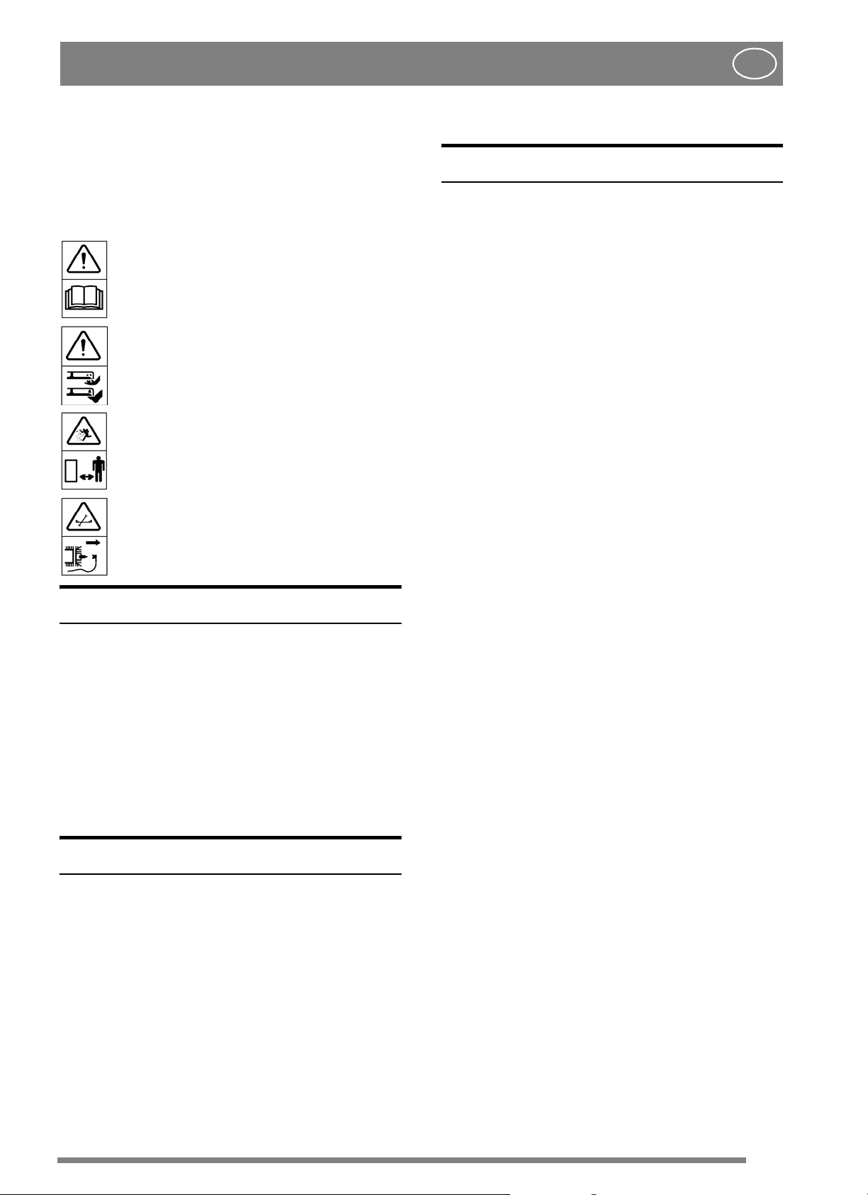
SYMBOLS
The following symbols can be found on the
machine to remind you of the care and attention
that are required during use.
The symbols mean:
Warning!
Read the instruction manual and the safety
manual before using the machine.
Warning!
Do not insert your hands or feet under the
cover when the machine is in operation.
Warning!
Watch out for discarded objects. Keep
onlookers away.
Warning!
Before starting repair work, remove the
spark plug cable from the spark plug.
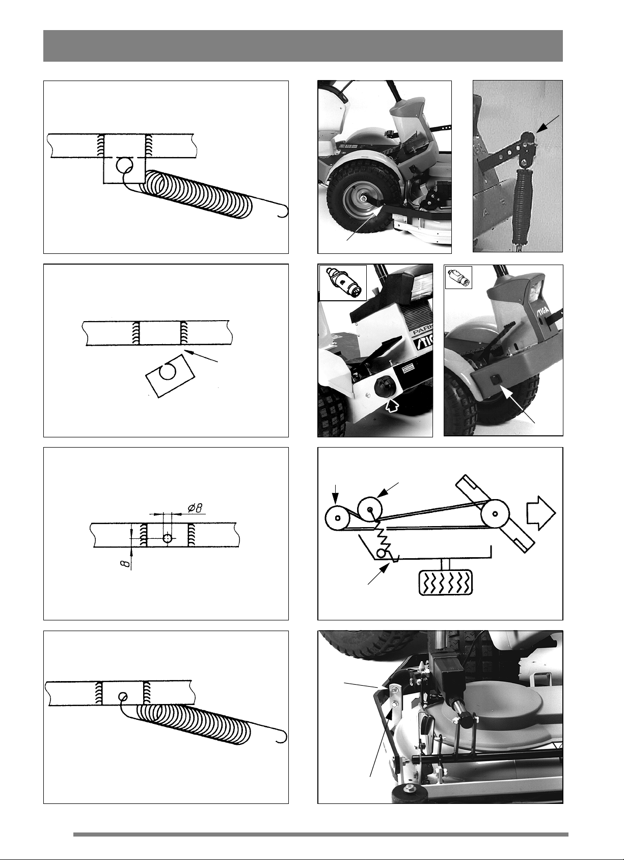
4. Install the spring in the new hole (fig. 4).
INSTALLATION
CUTTING DECK
1. Screw the cutting deck into the deck mounts D
(fig. 5a).
2. Attach the lift spring to the implement lifter (fig.
5b).
3. Install the lifting cylinder in the front lifting arm
by inserting the accompanying spacer in the hole
on the lifting cylinder and threading on two
washers, one on either side.Secure with screw and
nut (only applies to item no. 13-2921).
4. Connect the electrical contact to the socket on
the side of the machine (only applies to item no.
13-2921), (fig. 6).
V-BELT
1. Set the cutting height setting to an intermediate
position.
INTRODUCTION
ThiscuttingdeckmayonlybeusedwithPark
machines with a motor performance of at least 16
hp.
The cutting deck is available as standard in two
versions:
- with mechanical setting of the cutting height
(item no. 13-2915).
- with factory-fitted, electrical setting
of the cutting height (item no. 13-2921).
PREPARATIONS
Park, year models up to and including 1993:
In order for the deck to be used, the machine has to
be modified:
1. Remove the return spring for the articulated
joint
(fig. 1).
2. Saw off the spring mount flush with the frame
side member
(fig. 2).
2. Force the V-belt onto the machine’s centre
pulley F (fig. 7).
3. T ension the belt with belt idler G. The belt idler
should be on the left of the belt viewed from the
driver’s position.
4. Park -1999:
Hook the belt idler spring H in the floor on the
right side (fig. 7).
SETTING
In order forthe deckto cutevenly and attractively,
it has to be correctly adjusted:
1. Make sure the airpressurein the tyres is correct:
Front: 0.6 bar (9 psi).
Rear: 0.4 bar (6 psi).
2. Place the machine on a level floor.Undo screws
I (fig. 8).
3. Adjust the deck so that the front and rear edge of
the cover are the same height above the floor.
4. Tighten the screws.
3. Drill a new hole (Ø 8 mm), 8 mm from the lower
edge of the frame side member (fig. 3).
5
Page 6
GB
USE
ENGLISH
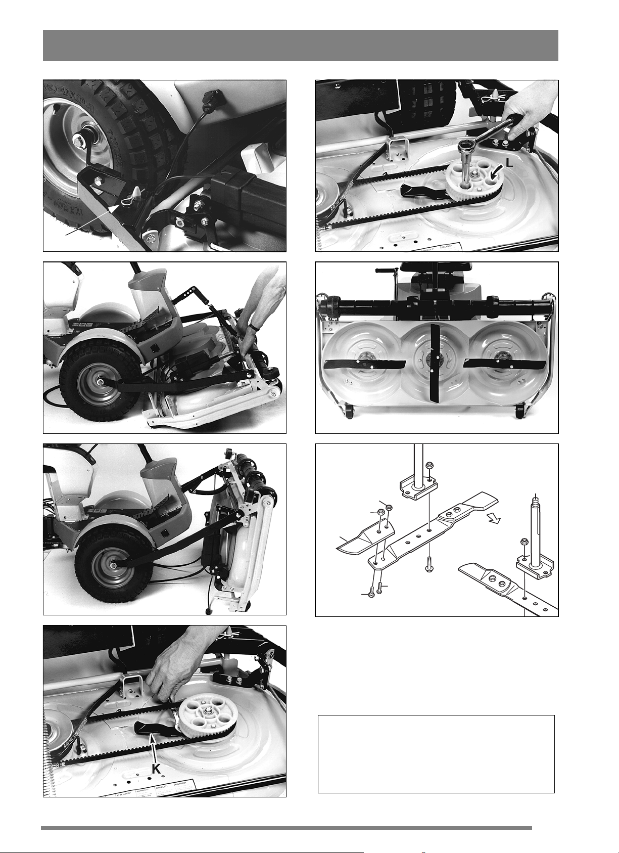
6. Fold up the deck until it is upright on the rear
support plates (fig. 11).
CUTTING HEIGHT
The cutting height can be varied from30to80 mm.
- item no. 13-2915 has seventeen fixed positions
for cutting height.
- item no. 13-2921 has continuously variable
adjustment of cutting height.
Note: Stated cutting heights apply when the
machine is on a firm surface.
CUTTING TIPS
For optimum ‘Multiclip effect’, follow these tips:
- cut frequently.
- run the motor at full revs.
- keep the underside of the cutting deck clean.
- use sharp blades.
- do not cut wet grass.
- cut twice (with different cutting heights) if
the grass is long.
MAINTENANCE
CLEANING
After each use, the underside of the cutting deck
should be rinsed off.
If the grass has dried solid, scrape clean the
underside.
If necessary, paint the underside to prevent
corrosion.
POSITIVE DRIVE BELTS
If one of the blades has struck a solid object (e.g. a
stone), the b elt tension may be altered. This can
lead to the positive drive belt ‘over-meshing’
which, in the long term, can damage the blades.
Adjust the belt tension if necessary:
1. Secure the tensioning arm on the hook.
2. Force the belt off the centre pulley F.
3. Dismantle the transmission cover.
4. Undo tensioning arm K (fig. 12).
PREPARATIONS
Unless otherwise stated, all service and
maintenance must be carried out on a stationary
machine when the motor is not running.
Prevent the machine from rolling by
always applying the parking brake.
Prevent unintentional starting of the
motor by always stopping the motor,
disconnecting the spark plug c able
from the spark plug and earthing it.
Disconnect the negative cable from the
battery.
MAINTENANCE TIPS
To make cleaning and maintenance easier, the
cutting deck can be folded up:
1. Set the cutting height setting to an intermediate
position (= drive belt minimum tension).
2. Secure the tensioning arm on the hook.
5. Undo the bearing box’s mounting screws L (fig.
13).
6. Tension the positive drive belt by pressing the
tensioning arm backwards.
7. Tighten the tensioning arm’s mounting screw.
8. Tighten the bearing box’s mounting screws.
9. Repeat with the other positive drive belt.
When replacing positive drive belts,
ensure that both the outer blades are
always at right-angles to the central
blade(seefig.14).
If the positive drive belts are incorrectly mounted,
the blades will strike each other because they
overlap.
Always check the position of the blades after
replacing a belt or adjusting belt tension.
REPLACING BLADES
Use protective gloves when changing
blades to avoid cutting yourself.
3. Force the belt off the centre pulley F.
4. Undo both pins J (fig. 9).
5. Grip the deck’s frame (fig. 10).
6
Ensure that the blades are always sharp. This
produces the best cutting results.
Page 7
ENGLISH
Always check the blades after a collision. If the
blade system has been damaged, defective parts
should be replaced.
Always use original spare parts. Nonoriginal spare parts can entail a risk of
injury, even if they fit the machine.
The cutting system comprises three blade
bars with two replaceable blades Y (fig. 15). When
replacing blades, both should be replaced to avoid
imbalance.
Install the new blades. Tighten screws V and W
properly. Tightening torque: V - 9.8 Nm, W - 24
Nm.
In the event of a powerful collision, the blades may
be bent out. Undo the locking nut X and fold back
the blade. Install a new original break bolt V.
Tighten the locking nuts X and Z.
GB
SPARE PARTS
STIGA original spare parts and accessories are
designed specifically for STIGA machines. Please
notethat‘non-original’ spare partsandaccessories
have not been checked or approved by STIGA:
The use of such parts and accessories
can affect the function and safety of the
machine.STIGA accepts no
responsibility for damage or injuries
caused by such products.
STIGA reserves the right to make alterations to the
product without prior notification.
7
Page 8

MOWING AHEAD
BOX 1006 · SE-573 28 TRANÅS
www.stiga.com
 Loading...