

Page 1
STIGA PARK
102 M
8211-3025-04
Page 2
J(x2)
X(x2)
V(x2)
Y(x2)
J(x2)
S(x4)
U(x2)
T(x2)
O(x4)
M(x4)
N(x4)
P(x4)
Q(x4)
O
M
N
P
Q
J
T
S
R
S
Q
P
M
N
O
U
2.
1.
Page 3
3.
4.
5.
6.
7.
8.
9.
10.
Page 4

11.
15.
16.
12.
13.
17.
14.
Page 5

Y
W
V
X
Z
18.
Denna produkt, eller delar därav, omfattas av följande
mönsterskydd:
This product, or part of it, is covered by the following
design registration:
Sverige/Sweden 62 435
Page 6

ENGLISH
GB
SYMBOLS
The following symbols are displayed on the machine in orderto remind you about the safety precautions and attention necessary when using the
machine.
The symbols mean:
Warning!
Read the instructionbook and safety manual before using the machine.
Warning!
Do not put hands or feet under the cover of
the machine when it is running.
Warning!
Bewareof objects being flung out. Keep
spectators away.
Warning!
Beforestartingany repairwork, removethe
spark plug cable from the spark plug.
PREPARATIONS
Park models up to 1993:
A modification must be made to the machine to use
the mower deck:
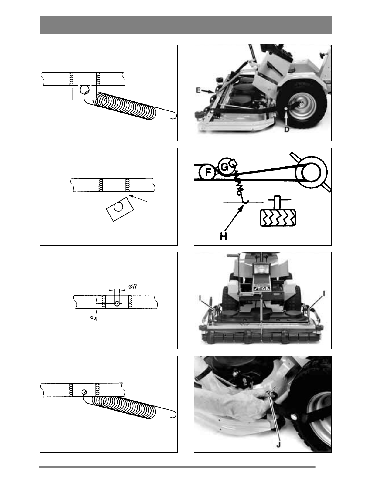
1. Dismantle the return spring for centre steering
(fig 3).
2. Saw off the spring bracket, level with the frame
side member (fig 4).
3. Drill a new hole (Ø 8 mm), 8 mm from the lower
edge of the frame side member (fig 5).
4. Fit the spring in the new hole (fig 6).
ASSEMBLY
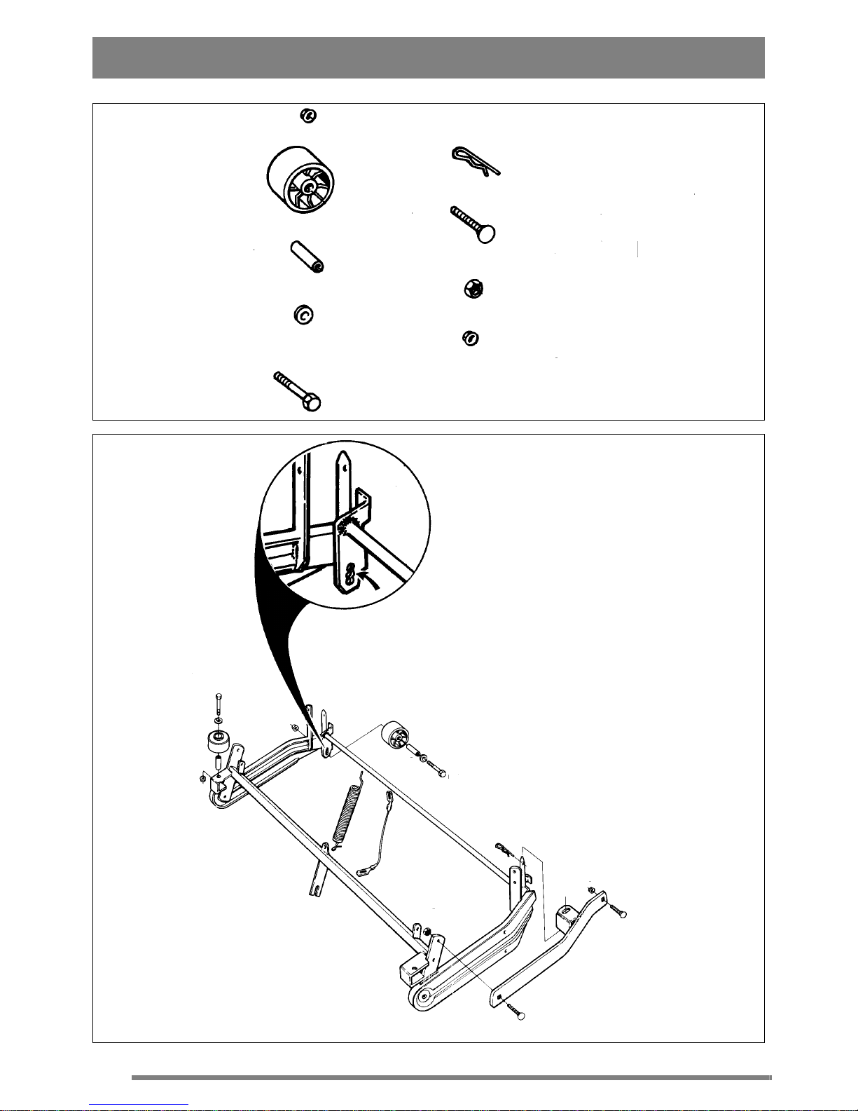
A plastic bag containing assembly parts are enclosed withthe mower deck (see fig 1)
SUPPORT ROLLERS
Fit the four support rollers M onto the mower deck
frame (fig 2).
The rear support rollersshould normallybe placed
in the centre hole.
SUPPORT ARMS
1. Bolt thesupportarms R securely onto themower
deckframe by means of thebolts S and lock nuts U
(fig 2). Donottighten too hard. It shouldbe possible
to move the support arms up and down.
2. Secure the support arms at the rear by means of
the pins J.
3. Fit the mower deck into the machine's accessory
bracketsD with the help ofthe screws S andthe nuts
T (fig 7).
4. Hook the mower deck's lifting spring E into the
attachment lift.
V-BELT
1. Adjust the height adjustment lever to position "5".
2. Lift the mower deck using the attachment lift.
3.Pullthe V-beltoverthemachine'scentral belt pulley F (fig 8).
4. Tension the belt using the tensionroller G. The
tension roller should be on the left of the belt seen
from the operator's position.
5. Hook the tension roller springH intothe flooron
the right hand side.
SETTING
For the attachment to mow evenly and cleanly it
needs to be adjusted correctly:
1. Make sure the tyre pressure is correct:
Front:0.06 MPa (0.6 kp/cm²).
Rear: 0.04 MPa (0.4 kp/cm²).
2. Place the machine on a flat surface. Loosen the
screws I (fig 9).
3. Adjust the mower deck so that the casing's front
and rear edges are the same height from the floor.
4. Tighten the screws.
USE
MOWING HEIGHT
Themowerdeck has 17fixedmowingheights,from
30 mm to 80 mm.
N.B. The stated mowing heights apply when the
machine is standing on firm ground.
Page 7

ENGLISH
GB
MOWING HINTS
For the best "Multiclip" effect follow this advice:
- mow regularly.
- use full throttle on the engine.
- keep the underside of the mower deck clean.
- use sharp blades.
- do not mow wet grass.
- mow twice (using different mowing heights)
if the grass is long.
MAINTENANCE
No service action must be taken on the
mower deck unless:
- the engine has been stopped.
- the ignition key has been removed.
- the spark plug cap has been removed
from the spark plug.
- the parking brake is engaged.
- the mower deck is disengaged.
MAINTENANCE TIPS
To facilitate cleaning and maintenance of the
mower deck it can be folded up:
1. Set the height adjustment lever i n position "5".
2. Lift up the mower deck using the attachment lift.
3. Unhook the tension roller spring H from the
floor (fig 8).
4. Pull off the v-belt from the central belt pulley F.
5. Loosen both locking pins J (fig 10).
6. Grip the mower deck's frame (fig 11).
7. Fold up the mower deck until it stands upright
on the rear support plates (fig 12).
CLEANING
After use the underside of the mower deck should
be hosed down.
If grass cuttings have dried on to the mower deck,
scrape the underside clean.
If necessary touch-up the underside using a suitable paint to prevent corrosion.
DRIVE BELTS
If any of the blades have hit a solid object (e.g. a
stone) thebelt tension can change. This means that
the drive belt can, "miss-mesh" which in the long
term can damage the blades.
If necessary adjust the drive belt:
1. Unhook the tension roller spring H from the
floor (fig 8).
2. Pryoff the drive belt from the central belt pulley
F.
3. Dismantle the transmission casing.
4. Loosen the tension arm K (fig 13).
5. Loosen the bearing box's fixing bolts L (fig 14).
6. Tension the drive belt by pressing the tension
arm backwards.
7. Tighten the tension arm's fixing bolts.
8. Tighten the bearing box's fixing bolts.
9. Carryout the same procedure forthe other drive
belt.
When changing the drive belts, make
sure that the outer blades are always at
90° to the centre blade (see fig 15).
If you fit the drive belts incorrectly the blades will
collide as they overlap each other.
Always check the position of the blades after
changing the drive belt or adjusting the tension.
CHANGING BLADES
Use protective gloves to prevent cuts
when changing blades/blade tips.
Make sure the blades are always sharp. This gives
the best mowing results.
Always check the blade(s) after an impact. If the
blade systemhas been damagedthe defective parts
must be changed.
Always use original spare parts. Using
non-original spare parts can result in
the risk of damage evenif they fit in the
machine.
The cutting system consists of three blade bars,
each with two interchangeable blade tips Y (fig
18). Bothblade tips shouldbe replaced at the same
time to avoid any imbalance.
Fit the new blade tips. Tighten the screws V and W
fully. Tightening torque: V - 9.8 Nm, W - 24 Nm.
And heavy impact can result in the blade tip being
folded aside. Loosen thelocking nutX andturn the
blade tip back to its correct position. Mount a new
Page 8

ENGLISH
GB
shear bolt V. Tighten the lock nuts X and Z.
SPARE PARTS
STIGA original spare parts and accessories are
constructedexclusively for STIGA machines.
Note that non original spare parts and accessories have not been checked or approved by STIGA.
Usage of such parts and accessories can influence the machines operability and safety. STIGA cannot be held responsible for injuries
caused by these products.
ACCESSORIES
Available as original electrical accessories for this
mower deck:
- unit lifter, art. no. 13-1953 (fig 16).
- mowing height adjuster, art. no. 13-1981
(fig 17).
STIGA reserves the right to modify the product without
prior notice.
CERTIFICATE
Category: Mower deck
Manufacturer: STIGA
Art. no.: 13-2913
Type: 102M
Cutting width: 102 cm
Cutting facility: Blade bar (x3)
Rotational speed: 3400 rpm
Guaranteed
sound power level: Park 12-13: 99 dB(A)
Park 16-18: 97 dB(A)
This product conforms to the specificationsin the
84/538 EEC Directive.
Place: Tranås, June 7th, 1998
Signature:
Certification Manager
EC - DECLARATION OF
CONFORMITY
Type: 102M
Art. no.: 13-2913
Serial no.: See mower deck
Manufacturer: STIGA AB, P.O. Box 1006,
S-573 28 Tranås, Sweden
Product: Mechanically driven mower deck
This productconforms to the Machine Directives
89/392/EEC, 91/386/EEC a nd 93/44/EEC with particular reference to Annex 1 in the Directive concerning essential health and safety requirements in connection with construction and manufacture.
Place: Tranås, June 7th, 1998
Signature:
Production Manager
 Loading...