

Page 1
STIGA PARK
DIESEL
DIESEL 4WD
BRUKSANVISNING
KÄYTTÖOHJEET
BRUGSANVISNING
BRUKSANVISNING
GEBRAUCHSANWEISUNG
INSTRUCTIONS FOR USE
MODE D’EMPLOI
GEBRUIKSAANWIJZING
SV.... 8
FI ... 18
DA..28
NO.38
DE ...48
EN...60
FR....71
NL...82
8211-0007-80
Page 2
1
S T
2
P
Q
3
D
E
4
M
4WD
HIJK
L
G
A
N
F
O
B
C
5
2WD
6
2WD
K
HI
G
J
R
2
Page 3
7
4WD
8
U
V
BA
9
X
10
E
W
Max
Y
11
12
Max
C
3
Page 4
C
13
B
C
14
A
D
15
17
16
0
F
1
18
P
V
4
Page 5
19
20
21
23
H
G
K
22
24
I
J
K
5
Page 6
25
26
27
29
28
4WD 2WD
30
6
Page 7

31
FG
32
33
H
J
7
Page 8

EN
ENGLISH
1 GENERAL
This symbol indicates W ARNING. Serious personal injury and/or damage to
property may result if the instructions
are not followed carefully .
Y ou must read these instructions for use
and the accompanying pamphlet
“SAFETY INSTRUCTIONS” carefully, before starting up the machine.
1.1 SYMBOLS
The following symbols appear on the machine.
They are there to remind you of the care and attention required during use and maintenance.
This is what the symbols mean:
Warning!
Read the instruction manual and the safety
manual before using the machine.
Warning!
Wa tch out for discarded objects. Keep onlookers away.
Warning!
Always wear hearing protectors.
Warning!
This machine is not designed to be driven
on public roads.
Warning!
The machine, equipped with original accessories, must not be driven in any direction on slopes with a gradient greater than
10º.
Warning!
Risk of crushing injuries. Keep hands and
feet well away from the articulated steering joint.
Warning!
Risk of burn injuries. Do not touch the silencer/catalytic converter.
1.2 References
1.2.1 Figures
The figures in these instructions for use are numbered 1, 2, 3, etc.
Components shown in the figures are marked A, B,
C, etc.
A reference to component C in figure 2 is written
“2:C”.
1.2.2 Headings
The headings in these instructions for use are numbered in accordance with the following example:
“1.3.1 General safety check” is a subheading to
“1.3 Safety checks” and is included under this
heading.
When referring to headings, only the number of the
heading is normally specified. E.g. “See 1.3.1”.
2 DESCRIPTION
2.1 Drive
2.1.1 2WD
The machine is rear wheel drive.
The rear axle is equipped with a hydrostatic trans-
mission with infinitely variable forward and reverse gear ratios.
The rear axle is also equipped with a differential to
facilitate turning.
Front mounted tools are driven by drive belts.
2.1.2 4WD
The machine has 4-wheel drive. The power from
the engine to the drive wheels is transferred hydraulically. The engine drives an oil pump, which
pumps oil through the rear and front axle drives.
The front axle and rear axle are connected in series, which means that the front wheels and rear
wheels are forced to rotate at the same speed.
To make turning easier, both axles are equipped
with differential.
Front-mounted implements are powered via drive
belts.
2.2 Steering
The machine is articulated. This means that the
chassis is divided into a front and a rear section,
which can be turned in relation to each other.
The articulated steering means that the machine
can turn around trees and other obstacles with an
extremely small turning radius.
2.3 Safety system
The machine is equipped with an electrical safety
system. The safety system interrupts certain activities that can entail a danger of incorrect manoeuvres. For example, the engine cannot be started if
the clutch-parking brake pedal is depressed.
The operation of the safety system must
always be checked every time before
use.
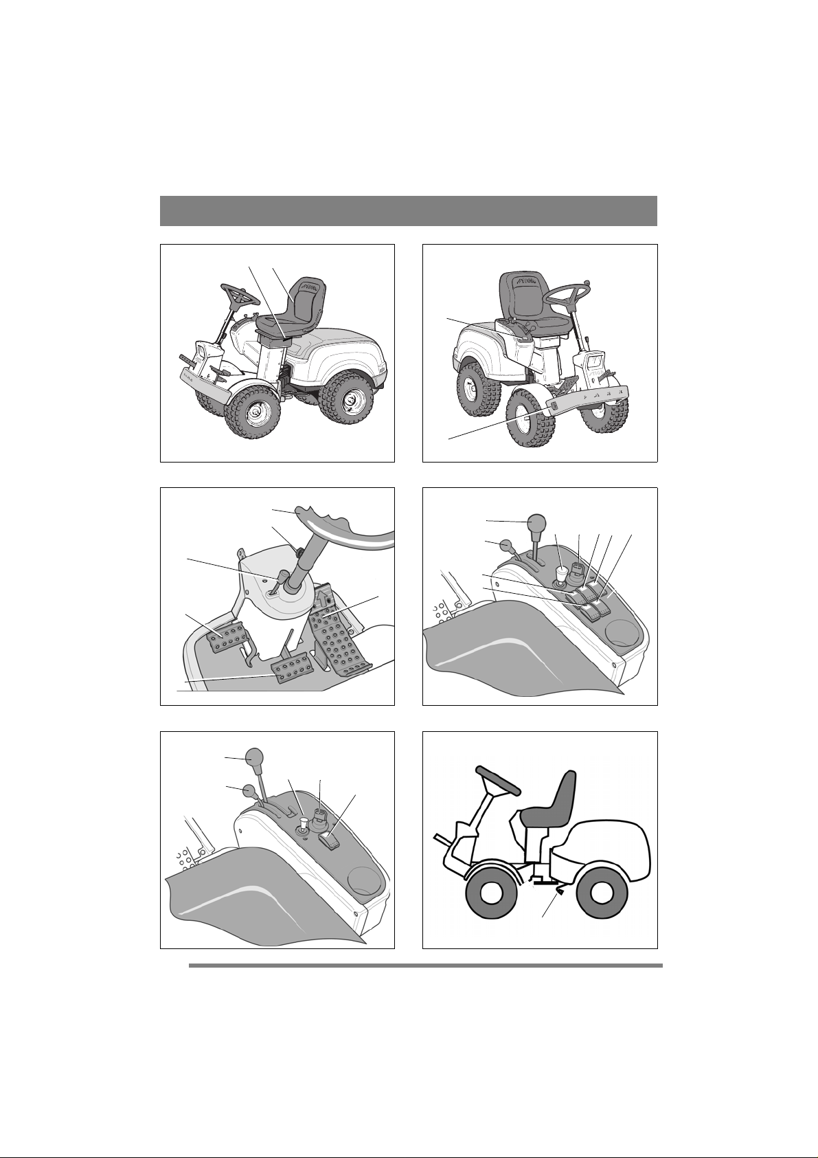
2.4 Controls
2.4.1 Implement lifter, mechanical (3:C)
(2WD)
To switch between working position and transport
position:
1. Depress the pedal fully.
2. Release the pedal slowly.
60
Page 9

ENGLISH
EN
2.4.2 Implement lifter, hydraulic (4:M)
(4WD)
The hydraulic implement lifter only works when
the engine is running and the clutch pedal and
parking brake pedal are not depressed. The implement lifter is controlled using the lever (4:M).
The lever has the following four positions:
Floating position. Move the lever to its
front position, where it locks. The implement is now lowered to its floating position.
In the floating position, the implement
always rests against the ground at the
same pressure and can follow the contours of the ground.
Use the floating position when carrying out work.
Lowering. The implement lowers regardless of its weight.
Locking in the transport position. The
lever has returned to the neutral position
after raising and lowering. The implement is locked in the transport position.
Raising. Move the lever to the rear position until the implement is in the highest
position (transport position). Then release the lever to lock in the transport position.
2.4.3 Clutch-parking brake (3:B)
Never press the pedal while driving.
There is a risk of overheating in the
power transmission.
The pedal (3:B) has the following three positions:
• Released. The clutch is not activated. The park-
ing brake is not activated.
• Depressed halfway. Forward drive disengaged.
The parking brake is not activated.
• Fully depressed. Forward drive disengaged.
The parking brake is fully activated but not
locked. This position is also used as emergency
brake.
2.4.4 Inhibitor, parking brake (3:A)
The inhibitor locks the “clutch-brake”
pedal in the depressed position. This function is used to lock the machine on slopes,
during transport, etc., when the engine is
not running.
The parking brake must always be released during operation.
Locking:
1. Depress the pedal (3:B) fully.
2. Move the inhibitor (3:A) to the right.
3. Release the pedal (3:B).
4. Release the inhibitor (3:A).
Unlocking:
Press and release the pedal (3:B).
2.4.5 Driving-service brake (3:F)
If the machine does not brake as expected when the pedal is released, the left
pedal (3:B) should be used as an emergency brake.
The pedal (3:F) determines the gearing ratio between the engine and the drive wheels (= the
speed). When the pedal is released, the service
brake is activated.
1. Press the pedal forward –
the machine moves forward.
2. No load on the pedal – the machine is stationary.
3. Press the pedal backward –
the machine reverses.
4. Reduce the pressure on the
pedal – the machine brakes.
There is an adjustment plate on the upper section
of the pedal. The adjustment plate can be adjusted
to three (3) positions to suit the driver’s foot.
2.4.6 Steering wheel (3:D)
The height of the steering wheel is infinitely adjustable. Undo the adjustment knob (3:E) on the
steering column and raise or lower the steering
wheel to the desired position. Tighten.
Do not adjust the steering wheel during
operation.
Never turn the steering wheel when the
machine is stationary with a lowered
implement. There is a risk of abnormal
loads on the servo and steering mechanisms.
2.4.7 Throttle control (4,5:G)
Control for setting the engine’s revs.
1. Full throttle – when the machine is in
operation, full throttle should always be
used.
2. Idling.
2.4.8 Headlight (4,5:H)
Pull-type control for turning the headlights on and
off.
61
Page 10

EN
ENGLISH
2.4.9 Ignition lock (4,5:I)
Ignition lock used for starting/stopping the engine.
There are 3 positions:
1. Stop position – the engine is short-circuited. The key can be removed.
2. Operating position
3. Start position – the electric start motor
is activated when the key is turned to the
spring-loaded start position. Once the engine has started, let the key return to operating position 2.
NOTE! If the engine should stop for any reason,
the key cannot be turned directly to position 3
due to a mechanical ignition lock. To start the
engine - turn the key back to position 1 and then
to positions 2 and 3.
2.4.10 Power take-off (4:K) (4WD)
Switch for engaging/disengaging the electromagnetic power take-off for operating front-mounted
accessories. Two positions:
1. Press the front part of the switch – the
power take-off is engaged. The symbol
will light up.
2. Press the rear part of the switch – the
power take-off is disengaged.
2.4.11 Power take-off (4,5:K)
A lever for engaging and disengaging the power
take-off for operating front-mounted accessories.
Two positions:
1. Lever in forward position – power takeoff disengaged.
2. Lever in backward position - power
take-off engaged.
2.4.12 Hour meter (2:P)
Indicates the number of working hours. Only
works when the engine is running.
2.4.13 Cruise control (4:N) (4WD)
A switch for activating the cruise control. The
cruise control locks the pedal (3:F) in the desired
position.
1. Press down the pedal (3:F) until the desired speed is obtained. Then press the
front part of the switch to activate the
cruise control. The symbol will light up.
2. Disengage the cruise control by releasing it with the pedal (3:B) or pressing the
rear part of the switch.
2.4.14 Cutting height adjustment (4,5:J)
The machine is equipped with a control for using
the cutting deck with electrical cutting height adjustment.
The switch is used to adjust the cutting
height in continuously variable positions.
The cutting deck is connected to the contact (2:Q).
2.4.15Rear Rake (4:L) (4WD)
The machine is fitted with a control for electrical
adjustment of a rear rake (available as an
accessory).
The switch is used to raise and lower the
rear rake.
Cables for connecting the rear rake are found at the
rear of the machine, to the left of the upper side of
the bumper. (4WD is prepared for a rear rake,
cables routed).
2.4.16 Sand spreader (4:O)
(4WD)
The machine has been designed for electrical adjustment of a sand spreader (accessory).
The switch is used to start and stop the
12V
spreader.
Cables for connecting the sand spreader are at the
rear of the machine.
2.4.17Clutch release lever
A lever for disengaging the variable transmission.
2WD is equipped with a lever, connected to the
rear axle. See (6:R).
4WD is equipped with two levers, connected to the
rear axle (7:A) and the front axle (7:B).
The disengagement lever must never be
between the outer and inner positions.
This overheats and damages the transmission.
The levers enable the machine to be moved by
hand without the help of the engine. Two positions:
The machine may not be towed over long distances
or at high speeds. The transmission could be damaged.
The machine must not be operated with
the forward most lever in the outer position. Risk of damage and oil leakage in
the front axle.
1. Lever in the inner position –
transmission engaged for normal
operation.
2. Lever in the outer position –
transmission disengaged. The
machine can be moved by hand.
62
Page 11

ENGLISH
EN
2.4.18 Seat (1:T)
The seat can be folded and adjusted frontrear. The seat can be adjusted as follows:
1. Move the control lever (1:S) upwards.
2. Set the seat to the desired position.
3. Release the control lever (1:S) to lock
the seat.
The seat is equipped with a safety switch that is
connected to the machine’s safety system. This
means that certain dangerous activities are not possible when there is nobody sitting on the seat. Also
see 4.5.2.
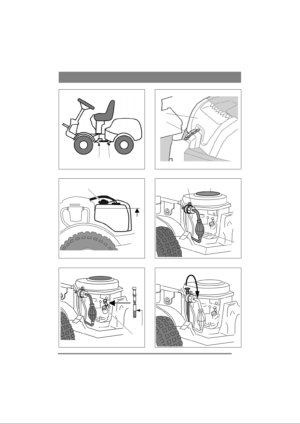
2.4.19 Engine casing (8:U)
In order to access the fuel cock, battery
and engine, the machine has an engine
casing that can be opened. The engine cas-
ing is locked with a rubber strap.
The engine casing is opened as follows:
1. Undo the rubber strap (8:V) at the front edge of
the casing.
2. Carefully lift the engine casing back.
Close in the reverse order.
The machine may not be operated un-
less the engine casing is closed and
locked. Risk of burns and crushing in-
juries.
2.4.20Quick-release mounting (31:H)
The quick connections can be separated,
which makes it very easy to shift between
the different implements.
The quick connections allow the deck to
be moved easily between the two posi-
tions:
• Normal position with fully tensioned belt.
• 4 cm behind the normal position with slackened
belt so that the deck gets closer to the base machine.
As the belt idler is released from the belt, the quick
connections simplify belt and deck replacement,
and also make shifting to the washing position and
service positions easier.
Releasing the belt tension:
1. Remove the locking pins (31:G) from both
sides.
2. Open the quick connections by depressing their
rear sections with your heel. See (31:F).
When the quick connections are
opened, the deck arms rest loosely in
the shaft sections. The deck must never
be set to the service position or washing
position without relocking the quick
connections after unhooking the deck
belt.
3. Carry out the necessary corrective action, e.g.:
• Unhook the belt.
• Replace the deck by unhooking the deck
arms. See fig. 33.
Tensioning the belt:
First tension one side and then the other according
to the instructions below.
Do not turn the lever using your hands.
Risk of crushing injuries.
1. Place your foot on the lever (32:J) and carefully
turn a half turn forwards.
2. Install the locking pin (31:G).
3.Carry out the above on the other side.
3 AREAS OF USE
The machine may only be used for the following
tasks using the genuine STIGA accessories stated.
Work Accessories, STIGA genuine
Mowing Using mowing decks: 125 Com-
Sweeping Using brush unit or collector
Snow clearance Using snow blade or snow
Grass clipping and
leaf collection
Grass and leaf
transport
Sand spreading Using sand spreader. Can also
Weeding on gravel
paths
Lawn edge trimming
Moss scarification Using moss scarifier.
The maximum vertical load on the towing hitch
must not exceed 100 N.
The maximum over-run load on the towing hitch
from towed accessories must not exceed 500 N.
NOTE! Before using a trailer – contact your insurance company.
NOTE! This machine is not intended to be driven
on public roads.
bi Pro, 125 Combi Pro El and
with flail mower.
brush unit. The use of a dust
guard is recommended with the
first option.
thrower Snow chains are recommended.
Using towed collector 30" or
42".
Using dump cart Standard, Maxi
or Combi.
be used for spreading salt. Snow
chains are recommended.
Using front-mounted hoe.
Using edge trimmer.
63
Page 12

EN
ENGLISH
4 STARTING AND OPERATION
The machine may not be operated unless the engine casing is closed and
locked. Risk of burns and crushing injuries.
4.1 Refuelling
Only use diesel which satisfies the minimum requirements of the following specifications:
EN 590
BS 2869 A1 / A2
ASTM D 975 - 1D / 2D
The engine must not be run on rape diesel (RME). Contact the engine supplier
for additional information.
1. Open the engine casing.
2. Open the fuel cap (9:X).
Filling fuel above the “Max” level in fig.
9 results in fuel leakage and risk of fire.
3. Fill with diesel to the “Max” level in fig. 9. If
filled above this level the fuel will leak out because it expands when heated.
4. Close the fuel cap.
Use winter fuel or add kerosene in ambient temperatures below 0°C. See the table below:
Lowest ambi-
ent tempera-
ture at start °C
0 to -10 20% -
-10 to -15 30% -
-15 to -20 50% 20%
-20 to -30 - 50%
Diesel is highly flammable. Always
store fuel in containers that are made
especially for this purpose.
Only fill or top up with fuel outdoors,
and never smoke when filling or topping up. Fill with fuel before starting
the engine.
Never remove the fuel cap or fill with
fuel while the engine is running or still
warm.
Proportion of kerosene
Summer fuel Winter fuel
4.2 Bleeding
The engine’s fuel system must be bled in the following instances:
• If the fuel tank has been run dry and air has been
drawn into the fuel system.
• After replacing the filter.
Bleed as follows:
1. Fill the tank with fuel.
2. Pump using the hand pump (10:Y) until all air
has been pumped out.
4.3 Level check, engine oil
On delivery, the crankcase is filled with SAE 10W 40 oil.
Always check the oil level before use to ensure it
is correct. The machine should be standing on
level ground.
Check the oil level as follows:
1. Wipe around the dipstick.
2. Unscrew and pull the dipstick up.
3. Wipe the dipstick.
4. Slide the dipstick down completely and pull up
again.
5. Read off the oil level. The oil level should be at
the “Max” mark as illustrated in fig. 11.
If the oil level is below the “Max” mark in fig. 11,
fill with oil as follows:
1. Unscrew the oil filler cap (11:C).
2. Fill with the necessary amount of oil. Applicable oil types, see “5.4”.
3. Check the level as above.
4. When the level is correct, reinstall the oil filler
cap and tighten.
The oil level must never exceed the “Max” mark as
illustrated in fig. 11. This can cause the engine to
overheat. Drain the oil to the correct level if the oil
level exceeds the “Max” mark.
4.4 Level check, transmission oil
See 5.8.1.
4.5 Safety checks
Check that the results of the safety checks below
are achieved when testing the machine in question.
The safety checks must always be carried out every time before use.
If any of the results below is not
achieved, the machine must not be
used! Take the machine to a service
workshop for repair.
64
Page 13

ENGLISH
EN
4.5.1 General safety check
Object Result
Fuel lines and connections.
Electrical cables. All insulation intact.
Exhaust system. No leaks at connections.
Oil lines No leaks. No damage.
Drive the machine
forwards/backwards and release
the driving-service
brake pedal.
Test driving No abnormal vibrations.
4.5.2 Electrical safety check
The operation of the safety system
should always be checked every time
before use.
Status Action Result
The clutch-brake
pedal is not
depressed.
The power take-off
is not activated.
The clutch-brake
pedal is depressed.
The power take-off
is activated.
Engine running.
The power take-off
is activated.
Status Action Result
Cruise control activated.(4WD)
Cruise control activated. (4WD)
No leaks.
No mechanical damage.
All screws tightened.
The machine will stop.
No abnormal sound.
Try to start. The engine
The driver gets up
from the seat.
The driver gets up
from the seat.
The driver gets up
from the seat.
The clutch-brake
pedal is depressed.
will not start.
The engine
will not start.
The power
take-off will
be disengaged.
The cruise
control will
be disengaged.
The cruise
control will
be disengaged.
4.6 Start
1. Do not keep your foot on the drive pedal.
2. Put the throttle control at full throttle.
3. Depress the brake pedal fully.
4. Turn the ignition key and start the engine. The
engine does not need to be preheated.
5. When starting from cold, do not make the machine work under load immediately, but let the
engine run for a few minutes first. This will allow the oil to warm up.
When in use, always operate the engine at full
throttle.
4.7 Power assisted steering (4WD)
Power assisted steering means that power from the
machine’s hydraulic system is supplied to the
steering wheel movements. This makes the machine very easy to steer when the engine is operating at working revs (full throttle).
The servo effect is reduced as the engine speed
drops.
4.8 Operating tips
Always check that there is the correct volume of
oil in the engine. This is particularly important
when operating on slopes. See 4.3.
Be careful when driving on slopes. No
sudden starting or stopping when driving up or down a slope. Never drive
across a slope. Move from the top down
or from the bottom to the top.
The machine may not be driven on
slopes greater than 10º in any direction.
Reduce the speed on slopes and when
making sharp turns in order to retain
control and reduce the risk of tipping
over.
Do not turn the steering wheel to full
lock when driving in top gear and at full
throttle. The machine can easily topple
over.
Keep hands and fingers well away from
articulated steering joint and seat
bracket. Risk of crushing injuries. Never drive with the engine casing open.
4.9 Stop
Disengage the power take-off. Apply the parking
brake.
If the machine is left unattended, remove the ignition key.
The engine may be very warm immediately after it is shut off. Do not touch the
cylinder or cooling fins. This can cause
burn injuries.
65
Page 14

EN
ENGLISH
4.10 Cleaning
To reduce the risk of fire, keep the engine, silencer , battery and fuel tank free
from grass, leaves and oil.
To reduce the risk of fire, regularly
check the machine for oil and/or fuel
leakage.
Clean the machine after each use. The following
instructions apply for cleaning:
• When washing the machine with water under
high pressure, do not point the jet directly at
axle seals, electrical components or hydraulic
valves.
• Do not spray water directly at the engine.
• Clean the engine with a brush and/or compressed air.
• Clean the engine’s cooling air intake (10:W).
5 MAINTENANCE
5.1 Service programme
In order to keep the machine in good condition as
regards reliability and operational safety as well as
from an environmental perspective, STIGA’s Service programme should be followed.
The contents of this programme can be found in
the attached service log.
Basic service
thorised workshop.
First service and intermediate service
carried out by an authorised workshop, but can
also be carried out by the user. The content of this
can be found in the service log and the actions are
described under “4 STARTING AND OPERATION” as well as below.
Servicing carried out at an authorised workshop
guarantees professional work using genuine spare
parts.
At each basic service and intermediate service carried out at an authorised workshop, the service log
is stamped. A service log presenting these services
is a valuable document that improves the machine’s second-hand value.
5.2 Preparation
All service and all maintenance must be carried out
on a stationary machine with the engine switched
off.
must always be carried out by an au-
should be
Prevent the machine from rolling by always applying the parking brake.
Prevent unintentional starting of the
motor by always stopping the motor
and disconnecting the negative cable
from the battery.
5.3 Tyre pressure
Adjust the air pressure in the tyres as follows:
Front: 0.6 bar (9 psi).
Rear: 0.4 bar (6 psi).
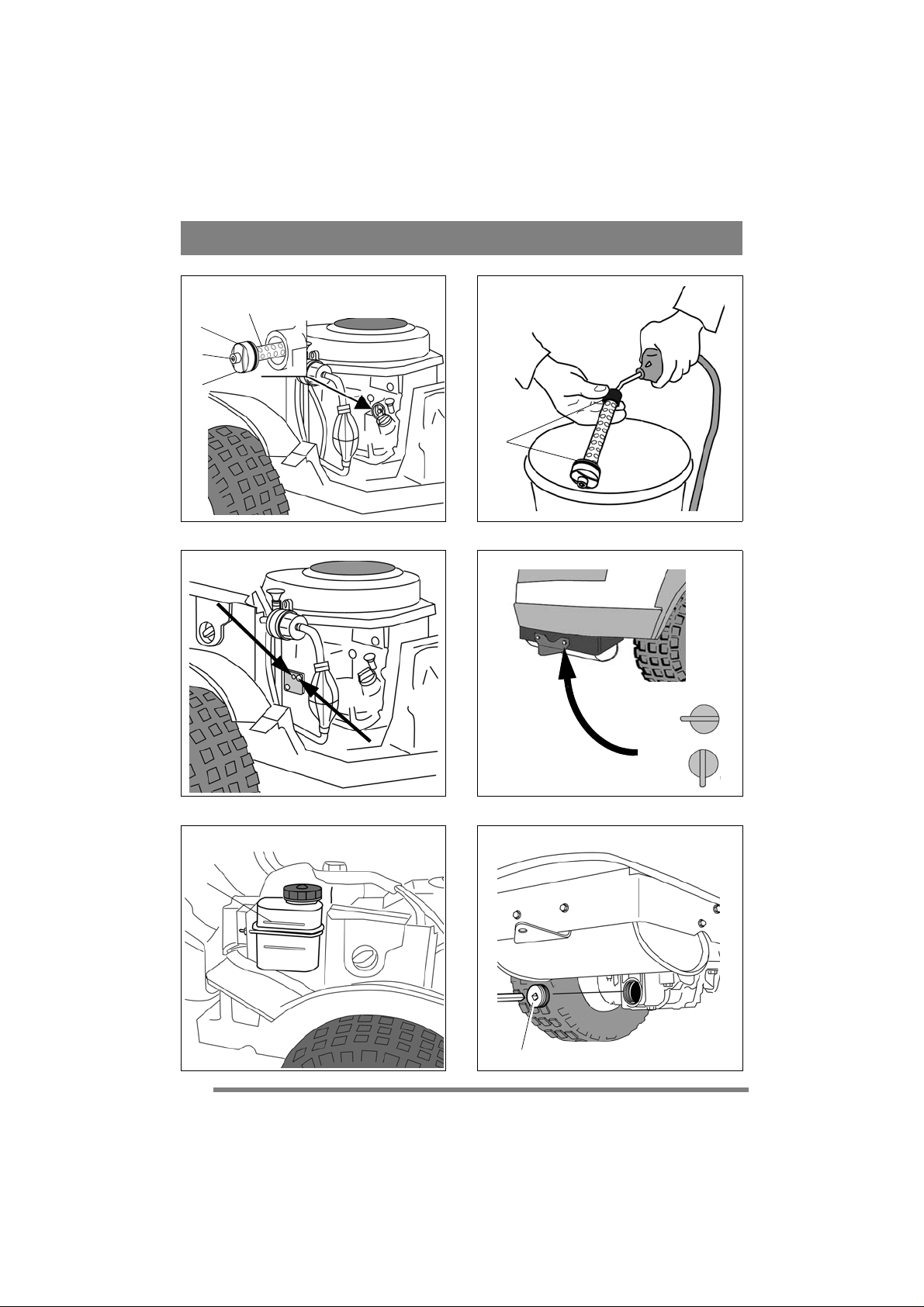
5.4 Changing engine oil
The engine oil must be changed for the first time
after 25 hours of operation and then every 250
hours of operation.
Use the following oil specifications:
ACEA-B2-E2 or API-CF-CG or SHPD.
Select the oil grade according to the table below.
Ambient temperature Oil grade
-24°C - +45°C. 10W/40
-30°C - +45°C. 5W/40
Use oil without any additives.
Do not overfill with oil. This can cause the engine
to overheat.
Change oil when the engine is warm.
The engine oil may be very hot if it is
drained off directly after the engine is
shut off. So allow the engine to cool a
few minutes before draining the oil.
1. Push the drain hose down so that it comes out
under the engine. See fig. 12
2. Tighten the clamp on the oil drain hose. Use a
polygrip or similar.
3. Move the clamp 3-4 cm up the oil drain hose
and pull out the plug.
4. Collect the oil in a container.
NOTE! Do not spill any oil on the drive belts.
5. Dispose of the oil according to local regulations.
6. Install the oil drain plug and slide the clamp
back so that it clamps over the plug.
7. To clean the oil filter, see 5.4.1 below before
continuing.
8. Remove the filler cap (11:C) and fill with oil.
The engine has a capacity of around 1.7 litres.
9. After filling the oil, start the engine and run at
idle speed for 30 seconds.
10.Check to see if there is any oil leakage.
11.Stop the engine. Wait for 30 seconds and then
check the oil level. See 4.3. Top up the oil if
necessary.
66
Stop the engine.
Page 15

ENGLISH
EN
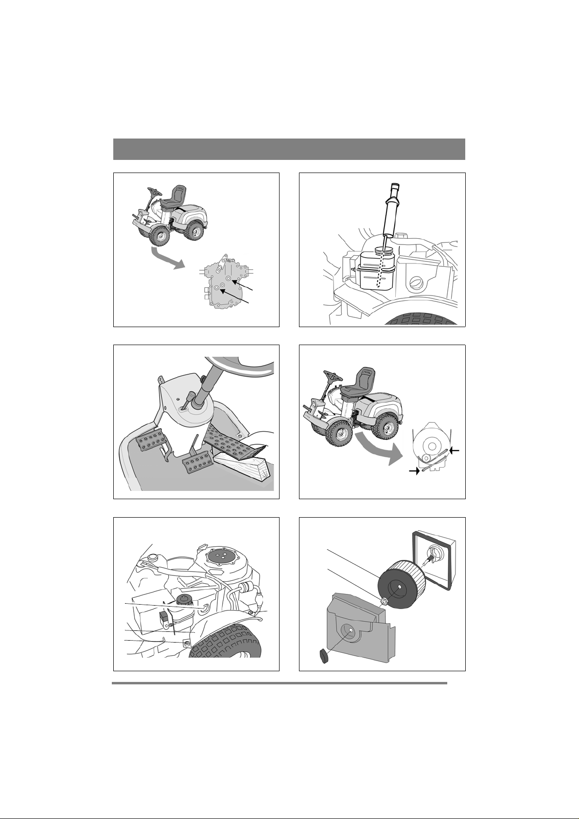
5.4.1 Oil filter
The oil filter must be cleaned after 1000 hours of
operation and when changing the oil. First drain
the engine oil and install the oil drain plug as
above. Then clean the oil filter as follows:
1. Clean the area around the filter (13:A)
2. Slacken off the screw (13:B) 5 turns.
3. Pull out the oil filter.
Never direct the flow of compressed air
towards the body. The penetration of
air into the blood stream can be fatal.
4. Clean the filter by blowing compressed air in
and out of the filter. See fig. 14.
5. Check/replace the gasket (14:D).
6. Lubricate the gasket (14:D) and slide the filter
in to its limit position.
7. Check that the ends of the tensioner spring
(13:C) lie flush against the filter. Tighten the
screws (13:B).
8. Continue with point 7 according to “5.4 Changing engine oil” above.
5.5 Engine screws
All screwed joints on the engine must be checktightened after 25 hours of operation and then every 250 hours of operation.
Exceptions:
• The cylinder head screws must not be touched.
• The fuel injection system’s adjustment screws,
as illustrated in fig. 15, must not be touched.
5.6 Fuel filter
The fuel filter (10:E) must be replaced after every
500 hours of operation.
After replacing, the fuel system must be bled. See
“4.2”.
Check that there is no fuel leakage once the new
filter has been installed.
5.7 Cleaning the fuel tank
During temperature changes water from the air
will condense in the fuel tank. The amount of water that condenses increases during large temperature changes and at high humidity . The water drops
and settles at the bottom of the fuel tank.
Condensation should be drained from the fuel tank
as necessary and at least once a year.
The engine must be cold when the condensation id drained, otherwise there is
a risk of fire.
Smoking, fires, sparks and other heat
sources are prohibited in the proximity
when the condensation is drained.
There is a fire risk.
Drain the condensation as follows:
1. Detach the drain hose from the its mounting under the rear bumper. See fig. 16.
2. Turn the drain cock (16:F) in its mounting to facilitate opening.
3. Insert the drain hose into a suitable container.
4. Open the drain cock and drain until all the water
has run out.
5. Close the drain cock and reset the cock and hose
in reverse order.
6. Dispose of the drained fluid according to local
regulations.
5.8 Transmission, oil (4WD)
The oil in the hydraulic power transmission must
be checked/adjusted and changed at the intervals
given in the table below.
1st time Then at
Action
Hours of operation
Checking – adjusting level. - 50
Changing the oil. 5 200
Type of oil: Synthetic oil 5W-50.
Oil quantity when changing: approximately 3.5 li-
tres.
5.8.1 Check – adjustment
1. Place the machine on a flat surface.
2. Read off the oil level in the reservoir. See fig.
20. The level should be level with the line.
3. If necessary, top up with more oil.
5.8.2 Draining
1. Run the machine at variable speeds for 10-20
minutes to heat up the transmission oil.
2. Position the machine completely horizontally.
3. Pull out both disengagement levers according to
fig. 7:A, B.
4. Place one container under the rear axle and one
under the front axle.
5. Open the oil reservoir by removing the cover.
Only a 3/8” square drive may be used
for the oil plug. Other tools will damage
the plug.
6. Remove the oil plug from the rear axle. Clean
the hole and use a 3/8” square drive. See figure
18.
7. Remove 2 drain plugs from the front axle. Use
a 12 mm socket. Allow the oil in the front axle
and pipes to run out. See fig. 19.
8. Check that the gaskets on the drain plugs of the
front axle are intact. See fig. 19. Reinstall the
plugs. Tightening torque: 15-17 Nm.
intervals
of
67
Page 16

EN
ENGLISH
The oil plug will be damaged if it is
tightened more to than 5 Nm.
9. Check that the gasket on the oil plug of the rear
axle is intact. See fig. 18:V . Reinstall in the rear
axle. Tighten the oil plug to 5 Nm.
10.Draw out the oil from the deeper section of the
reservoir using an oil extractor. See fig. 20.
11.Dispose of the oil according to local regulations.
5.8.3 Filling
The engine must never be run when the
rear clutch release lever is pushed in
and the front clutch release lever is
pulled out.
This will damage the front axle seals.
1.Fill the oil reservoir with the new oil.
If the engine is run indoors, exhaust extraction equipment must be connected
to the engine’s exhaust pipe.
2. Check that the rear axle’s clutch release lever is
pulled out.
3. Start the engine. When the engine is started, the
front axle’s clutch release lever slides inwards
automatically.
4. Pull out the front axle’s clutch release lever.
NOTE! The oil is drawn into the system very
quickly. The reservoir must always be
topped up. Air must never be drawn in.
5. Set the accelerator pedal to the forward position
by blocking it using a wooden wedge. See fig.
14. Fill the oil reservoir by hand using new oil.
6. Run in the forward position for one minute.
7. Move the wooden wedge and set the accelerator
pedal to the reverse position. Continue filling
with oil.
8. Run in reverse mode for one minute.
9. Change driving direction once every minute as
above and continue filling with oil until the
bubbling in the reservoir stops.
10.Switch off the engine, install the oil reservoir
cover and close the engine cover.
11.T est drive for several minutes and adjust the oil
level in the reservoir.
5.9 Belt transmissions
After 5 hours of operation, check that all the belts
are intact and undamaged.
5.10Steering
The steering must be checked/adjusted after 5
hours of operation and thereafter after 100 hours of
operation.
5.10.1Checks
Briefly turn the steering wheel back and forth.
There must be no mechanical clearance in the
steering chains.
5.10.2Adjustment
Adjust the steering chains if required as follows:
1. Put the machine in the straight-ahead position.
2. Adjust the steering chains with the two nuts, located under the central point. See fig. 22.
3. Adjust both nuts by the same amount until there
is no clearance.
4. Test drive the machine straight forwards and
check that the steering wheel is not off centre.
5. If the steering wheel is off centre, undo one nut
and tighten the other.
Do not over-tighten the steering chains. This will
cause the steering to become heavy and will increase wear on the steering chains.
5.11 Battery
If acid comes into contact with the eyes
or skin, this can cause serious injuries.
If any part of the body has come into
contact with acid, rinse immediately
with copious amounts of water and seek
medical assistance as soon as possible.
The battery is a valve-regulated battery with 12 V
nominal voltage. The battery fluid does not need to
and cannot be checked or topped up. The only
maintenance that is required is charging, for example after extended storage.
The battery must be fully charged before being used for the first time. The
battery must always be stored fully
charged. If the battery is stored while
discharged, serious damage will occur.
5.11.1 Charging with the engine
The battery can be charged using the engine’s generator as follows:
1. Install the battery in the machine as shown below.
2. Place the machine outdoors or install an extraction device for the exhaust fumes.
3. Start the engine according to the instructions in
the user guide.
4. Allow the engine to run continuously for 45
minutes.
5. Stop the engine. The battery will now be fully
charged.
68
Page 17

ENGLISH
EN
5.11.2 Charging using battery charger
When charging using a battery charger, a battery
charger with constant voltage must be used.
Contact your dealer to purchase a battery charger
with constant voltage.
The battery can be damaged if a standard type
battery charger is used.
5.11.3 Removal/Installation
The battery is placed under the engine casing. During removal/installation, the following applies regarding connection of the cables:
• During removal. First disconnect the black cable from the battery’s negative terminal (-).
Then disconnect the red cable from the battery’s
positive terminal (-).
• During installation. First connect the red cable
to the battery’s positive terminal (+). Then connect the black cable to the battery’s negative terminal (-).
If the cables are disconnected/connected in the wrong order, there is a risk of
a short-circuit and damage to the battery.
If the cables are interchanged, the generator and the battery will be damaged.
Tighten the cables securely. Loose cables can cause a fire.
The engine must never be driven with
the battery disconnected. There is a risk
of serious damage to the generator and
the electrical system.
5.11.4 Cleaning
If the battery terminals are coated with oxide, they
should be cleaned. Clean the battery terminals with
a wire brush and lubricate them with terminal
grease.
5.12 Air filter, engine
A damaged air filter allows contaminated air into the engine. This will cause serious damage to the engine.
The air filter must be cleaned after every 50 hours
of operation. The oil filter must be replaced as necessary, or after every 500 hours of operation.
NOTE! Clean/replace the filter more often if the
machine operates in dusty conditions.
Remove/install the air filters as follows.
1. Disconnect the splash guard (23:G) by removing the nuts (23:K).
2. Clean carefully around the air filter housing.
3. Disconnect the air filter housing by slackening
off the wing nut (23:H).
4. Remove the filter (24:I) by slackening off the
ridged nut (24:J).
Never direct the flow of compressed air
towards the body. The penetration of
air into the blood stream can be fatal.
5. Clean off any dry dirt on the filter by blowing
compressed air in and out of the filter. The pressure must not exceed 5 bar.
Check for cracks or other damage after cleaning. This can be visually checked against a light
source.
Check that the filter’s mating surfaces are free
of faults.
If the filter is damaged, it must be replaced.
If the filter is contaminated by moisture/oily
dirt, it must be replaced.
6. Assemble in reverse order.
Do not use compressed air or petroleum based solvents such as kerosene to clean the paper filter insert. This will damage the filter.
5.13 Air intake
See 10:W. The engine is air-cooled. A blocked
cooling system can damage the engine. Clean the
engine’s air intake after 50 hours of operation.
More meticulous cleaning of the cooling system is
carried out during each basic service.
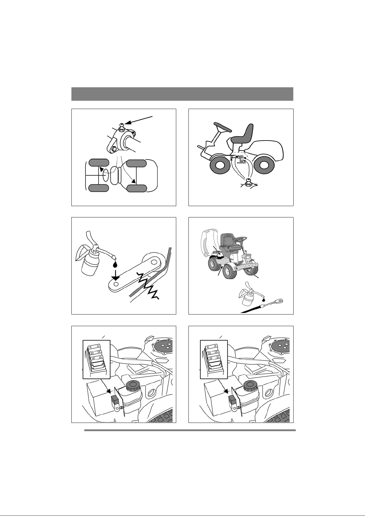
5.14 Lubrication
All lubrication points in accordance with the table
below must be lubricated every 50 hours of operation as well as after every wash.
Object Action Fig-
ure
Wheel bearing
Centre point 4 grease nipples.
Steering
chains
Tensioning
arms
Control
cables
2 grease nipples.
Use a grease gun filled with
universal grease. Pump until
the grease emerges.
Use a grease gun filled with
universal grease. Pump until
the grease emerges.
Brush the chains clean with a
wire brush.
Lubricate with universal
chain spray.
Lubricate the bearing points
with an oil can when each
control is activated.
Ideally carried out by two
people.
Lubricate the cable ends with
an oil can when each control
is activated.
Must be carried out by two
people.
25
26
-
27
28
69
Page 18

EN
ENGLISH
5.15 Fuses
If any of the faults listed below occurs, replace the
relevant fuse. See fig. 29/30.
Fault Fuse
The engine does not start or starts and
stops immediately. The battery is
charged.
Sand spreader and electrical cutting
height adjustment do not work.
All electrical functions are out of
operation. The battery is charged.
10 A
20 A
30 A
6 PATENT - DESIGN REGISTRA-
TION
This machine or parts thereof is covered by the following patent and design registration:
SE9901091-0, SE9901730-3, SE9401745-6,
US595 7497, FR772384, DE69520215.4,
GB772384, SE0301072-5, SE04/000239 (PCT),
SE0401554-1, SE0501599-5.
70
GGP reserves the right to make alterations to the
product without prior notification.
 Loading...