

Page 1
STIGA VILLA
85 M
8211-3039-02
Page 2
1.
2.
A
B
3.
4.
5.
7.
6.
8.
2
Page 3
R
L
9.
10.
Z
X
Y
11.
V
W
3
Page 4

4
Page 5

ENGLISH
GB
SYMBOLS
The following symbols can be found on the machine to remind you of the care and attention that
are required during use.
The symbols mean:
Warning!
Read the instruction manual and the safety
manual before using the machine.
Warning!
Do not insert your hands or feet under the
cover when the machine is in operation.
Warning!
Watch out for discarded objects. Keep onlookers away.
Warning!
Before starting repair work, remove the
spark plug cable from the spark plug.
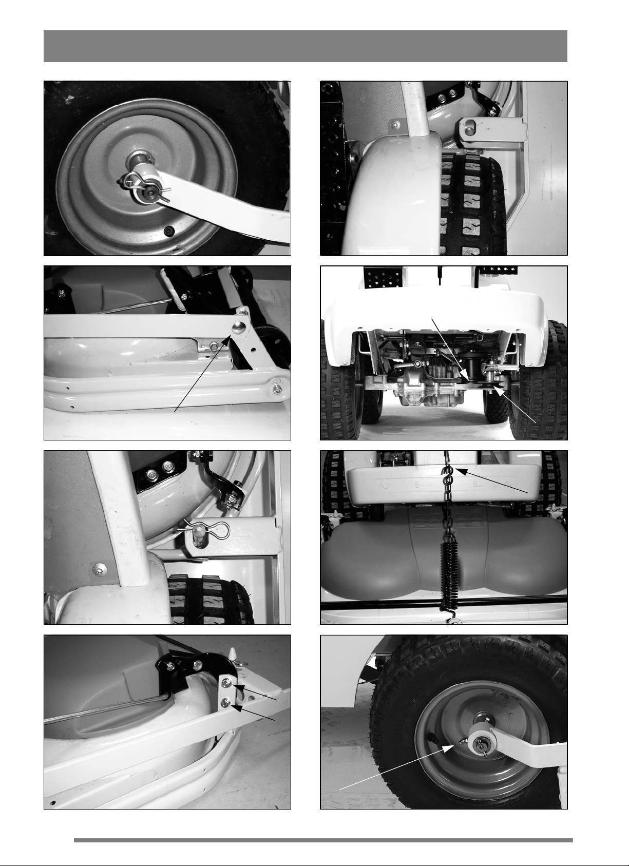
the left (viewed from the driver’s position).
6. Raise rear edge of the deck so that the deck can
besecuredwiththelockingpinonbothsides
(fig. 5).
7. Hook the elevating chain’s upper S-hook into
the machine’s lifting arm (fig. 6).
The ratio between the chain and spring is pre-set
for optimum ground pressure. If necessary, the position of the spring can be changed.
SETTING
In orderforthedecktocutevenly and attractively,
it has to be correctly adjusted:
1. Make sure the air pressure in the tyresis correct:
Front: 0.4 bar (6 psi).
Rear: 1.2 bar (17 psi).
2. Place the machine on a level floor. Undo the
screws (fig. 7).
3. Adjust so that the front and rear edge of the cover are the same height above the floor.
INSTALLATION
DECK ARMS
1. Remove the locking pin and the outermost flat
washer from the machine’s steering knuckle.
2. Thread the left and right deck arms onto the machine’s steering knuckle. Place the flat washer on
the steering knuckle and secure with the locking
pin (fig. 1).
CUTTING DECK
1. Raise the deck arms and place the cutting deck
in front of the machine. Set to cutting height 5.
2. Fold down the deck arms over the cutting deck
so that the pins in the deck go through the holes in
the deck arms (fig. 2).
3. Install the left and right deck arms in the cutting
deck’s front two corners. Use the existing screw
and locking nut (fig. 3). Tighten the locking nut,
but not so hard that the arm is totally secured.
4. Force the V-belt onto the machine’s pulley A
(fig. 4).
4a. Cutting normal length grass:
Adjustthedecksothatthefrontandrearedgeof
the cover are the same height above the floor. This
position gives the best ‘Multiclip effect’, i.e. the
grass is cut up best.
4 After setting, tighten the screws properly.
USE
CUTTING HEIGHT
The cutting height can be variedbetween a number
of fixed positions, from 30 to 80 mm.
Note: Stated cutting heights apply when the machine is on a firm surface.
CUTTING TIPS
For optimum ‘Multiclip effect’, follow these tips:
- cut frequently.
- run the engine at full revs.
- keep the underside of the cutting deck clean.
- use sharp blades.
- do not cut wet grass.
- cut twice (with different cutting heights) if
the grass is long.
5. Tension the belt with belt idler B. The belt idler
should be on the inside of the belt and pull out to
5
Page 6

GB
ENGLISH
SERVICE AND MAINTENANCE
PREPARATIONS
Unless otherwise stated, all service and maintenancemust be carriedout on a stationary machine
when the engine is not running.
Always use genuine spare parts. Nongenuine spare parts can entail a risk of
injury, even if they fit the machine.
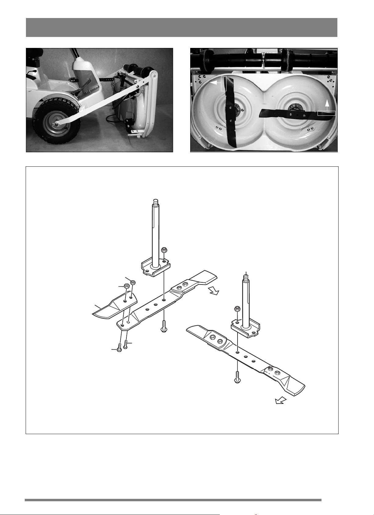
The cutting system comprises two blade bars with
tworeplaceablebladesY(fig.11).When replacing
blades, both should be replaced to avoid imbalance.
Preventthe machine from rolling by always applying the parking brake.
Prevent unintentional starting of the
engine by always stopping the engine,
disconnecting the spark plug cabl e
from the spark plug and earthing it.
Disconnect the negative cable from the
battery.
LUBRICATION
The deck arms are equipped with grease nipples (fig.8).
Lubricate these after every 25 hours of operation
(or at l east once per season) with universal grease.
MAINTENANCE TIPS
To make cleaning and maintenance easier, the cutting deck can be folded up:
1. Set the cutting height setting to cutting height 5.
2. Remove the locking pins and release the rear
edge of the deck (fig. 5).
3. Secure the tensioning arm on the hook.
3. Force the belt off the machine’s pulley.
7. Fold up the deck to the vertical position (fig. 9).
Install the new blades. Tighten screws V and W
properly. Tightening torque: V - 9.8 Nm, W - 24
Nm.
In the event of a powerful collision, the blades may
be bent out. Undo the locking nut X and fold back
the blade. Install a new genuine break bolt V.
Tighten the locking nuts X and Z.
POSITIVE DRIVE BELT
Both blades are powered inside the deck by a positive drive belt.
If one of the blades has struck a solid object (e.g. a
stone), the belt tension may be altered. This can
lead to the positive drive belt ‘over-meshing’
which, in the long term, can damage the blades.
Following a powerful collision, always
check that both blades are at right-angles to each other (fig. 10).
The working areas of the blades overlap each other. If the blades’ position in relation to each other
has been altered, there is a considerable risk of the
blades striking each other. This can entail serious
damage to the cutting d eck.
If this isthe case,take the machine and cutting deck
to a service workshop for repair and inspection.
CLEANING
After each use, the underside of the cutting deck
should be rinsed off.
If the grass has dried solid, scrape clean the underside.
If necessary, touch up the underside with pain t to
prevent corrosion.
REPLACING BLADES
Wear protective gloves when changing
blade(s) to avoid cutting yourself.
Ensure that the blades are always sharp. This produces the best cutting results.
Always check the blade(s) after a collision. If the
blade system has been damaged, defective parts
should be replaced.
6
SPARE PARTS
STIGA genuine spare parts and accessories are designed specifically for STIGA machines. Please
note that ‘non-genuine’ spare parts and accessories
have not been checked or approved by STIGA.
The use of such parts and accessories
can affect the function and safety of the
machine. STIGA accepts no responsibility for damage or injuries caused by
such products.
STIGA reserves the right to make alterations to the
product without prior notification.
Page 7

ENGLISH
GB
7
Page 8

MOWING AHEAD
BOX 1006 · SE-573 28 TRANÅS
www.stiga.com
 Loading...