

Page 1

STIGA PARK
121M
8211-3011-07
Page 2
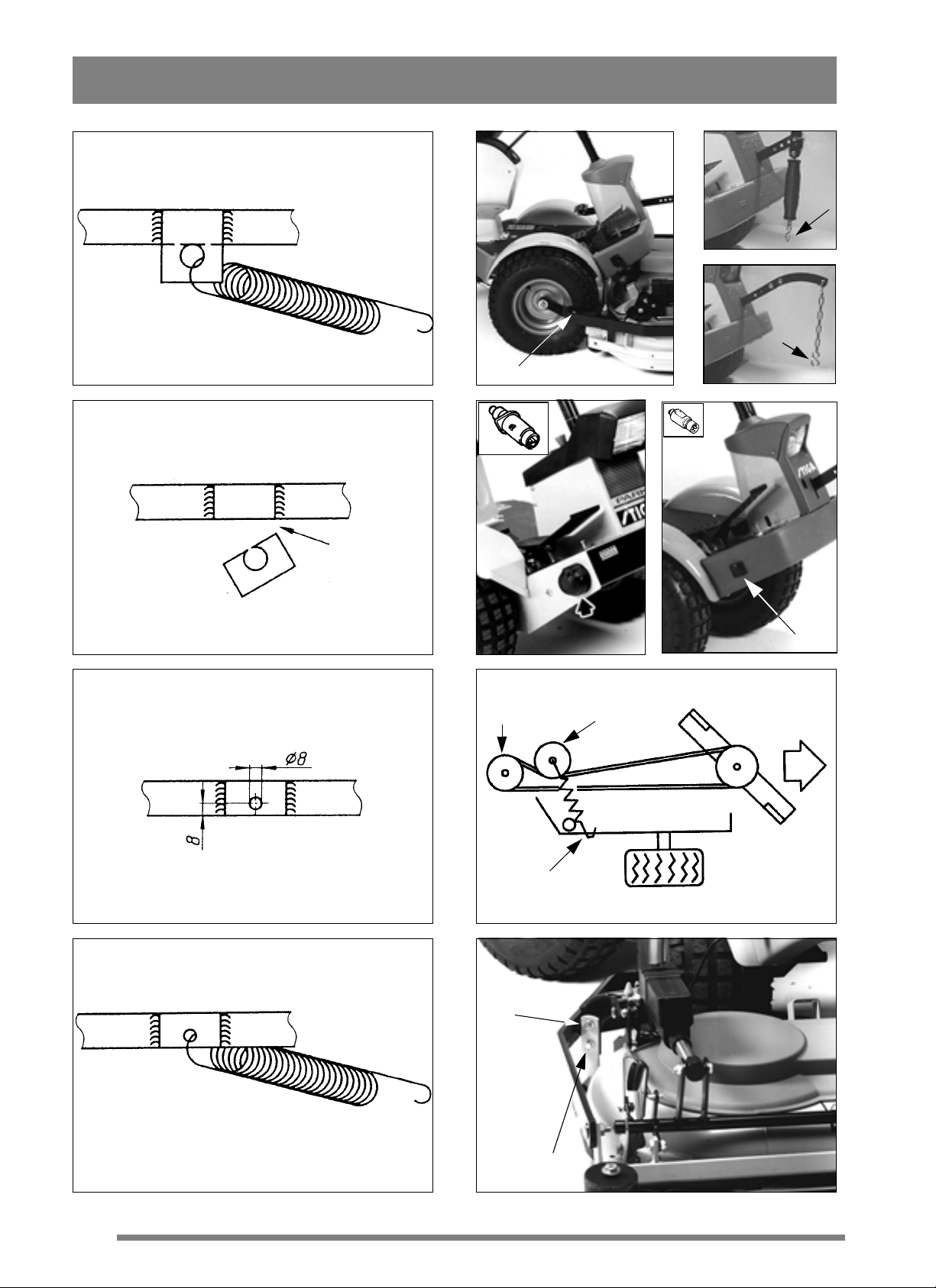
1. Park -1993
5a.
5b.
D
5c. Pro18 - Pro20
2. Park -1993
3. Park -1993
6a. Park -1999
F
H
7.
I
6b. Park 2000-
G
4. Park -1993
2
I
8.
Page 3

J
9.
13.
10.
11.
14.
Z
V
W
15.
Denna produkt, eller delar därav, omfattas av följande
mönsterskydd:
This product, or part of it, is covered by the follow ing
design registration:
Sverige/Sweden 62 435
Tyskland/Germany M97 07 997.9 (pending)
X
Y
12.
3
Page 4

ENGLISH
SYMBOLS
The following symbols are displayed on the machine in order to remind you about the safety precautions and attention necessary when using the
machine.
The symbols mean:
Warning!
Read the instruction book and safety manual before using the machine.
Warning!
Do not put hands or feet under the cover of
the machine when it is running.
Warning!
Beware of objects being flung out. Keep
spectators away.
Warning!
Beforestartinganyrepair work,remove the
spark plug cable from the spark plug.
GB
ASSEMBLY
MOWER DECK
1.Bolt the mower decktothe attachment brackets D
(fig 5a).
2. Then hook the l ower S-hook on to the mower
deck (fig 5b-c).
3. Connect the electrical contact to the outlet on the
side of the machine (applies only to art. no. 13-
2921), (fig. 6).
V-BELT
1. Set the height adjustment to an intermediate position.
2. Lift the mower deck using the attachment lift.
3. Pull the v-belt over the machine's central belt pulley F (fig 7).
4. Tension the belt using the tension roller G. The
tension roller should be on the left of the belt seen
from the operator's position.
INTRODUCTION
ThismowerdeckcanonlybeusedforParkmachines with a motor output of at least 16 hp.
The mower deck is available in two versions as
standard:
- with mechanical setting of the mowing height
(art. no. 13-2915)
- with factory-fitted, electrical setting of the
mowing height (art. no. 13-2921).
PREPARATIONS
Park models up to 1993:
A modification must be made to the machine to use
the mower deck:
1. Dismantle the return spring for centre steering
(fig 1).
2. Saw off the spring bracket,level with the frame
side member (fig 2).
5a. Park -1999:
Hookthe tension rollerspringH into theflooron the
right hand side (fig 7).
5b. Park 2000- :
Hook the tension roller spring H into the fastener,
just behind the front right wheel (fig 7).
SETTING
For the attachment to mow evenly and cleanly it
needs to be adjusted correctly:
1. Make sure the tyre pressure is correct:
Front: 0.6 bar (9 psi).
Rear: 0.4 bar (6 psi).
2. Place the machine on a flat surface. Loosen the
screws I (fig 8).
3. Adjust the mower deck so that the casing's front
and rear edges are the same height from the floor.
4. Tighten the screws.
USE
3. Drill a new hole (Ø 8 mm), 8 mm from the lower
edge of the frame side member (fig 3).
4. Fit the spring in the new hole (fig 4).
MOWING HEIGHT
The mowing height may vary from 30 to 80 mm:
- art. no. 13-2915 has seventeen fixed mowing
5
Page 5

GB
ENGLISH
height positions
- art. no. 13-2921 has stepless adjustment of the
mowing height.
N.B.Thestatedmowingheightsapplywhenthe
machine is standing on firm ground.
MOWING HINTS
For the best "Multiclip" effect follow this advice:
- mow regularly.
- use full throttle on the engine.
- keep the underside of the mower deck clean.
- use sharp b lades.
- do not mow wet g rass.
- mow twice (using different mowing heights)
if the grass is long.
MAINTENANCE
PREPARATIONS
Unless otherwise stated, all service and maintenancemustbeperformedonamachinethatis
standing still where the engine has been switched
off.
Preventthe machine fromrolling, by always applying the parking brake.
CLEANING
After use the underside of the mower deck should
be hosed down.
If grass cuttings have dried on to the mower deck,
scrape the underside clean.
If necessary touch-up the underside using a suitable paint to prevent corrosion.
DRIVE BELTS
If any of the blades have hit a solid object (e.g. a
stone) the belt tension can change. This means that
the drive belt can, "miss-mesh" which in the long
term can damage the blades.
If necessary adjust the drive belt:
1. Unhook the tension roller spring H (fig 7).
2. Pry off the drive belt from the central belt
pulley F.
3. Dismantle the transmission casing.
4. Loosen t he tension arm K (fig 12).
5. Loosen the bearing box's fixing bolts L (fig 13).
6. Tension the drive belt by pressing the tension
arm b ackwards.
7. Tighten the tension arm's fixing bolts.
Prevent involuntary engine start by always stopping the engine, loosening the
spark plug cable from the sparking
plug and earthing it. Remove the minus
(-) cable from the battery.
MAINTENANCE TIPS
To facilitate cleaning and maintenance of the
mower deck it can be folded up:
1. Set the mowingheight adjustmentto an interme-
diate position (= least tension on the drive belt).
2. Lift up the mower deck using the attachment lift.
3. Unhook the tension roller spring H (fig 7).
4. Pull off the v-belt from the central belt pulley F.
5. Loosen both locking pins J (fig 9).
6. Grip the mower deck's frame (fig 10).
7. Fold up the mower deck until it stands upright
on the rear support plates (fig 11).
8. Tighten the bearing box's fixing bolts.
9. Carry out the same procedurefor the other drive
belt.
When changing the drive belts, make
sure that the outer blades are always at
90° to the centre blade (see fig 14).
If you fit the drive belts incorrectly the blades will
collide as they overlap each other.
Always check the position of the blades after
changing the drive belt or adjusting the tension.
CHANGING BLADES
Use protective gloves to prevent cuts
when changing blades/blade tips.
Make sure the blades are always sharp. This gives
the best mowing results.
Always check the blade(s) after an impact. If the
bladesystem has been damaged the defective parts
must be changed.
6
Page 6

ENGLISH
Always use original spare parts. Using
non-original spare parts can result in
the risk of damage even if they fit in the
machine.
The cutting system consists of three blade bars,
each with two interchangeable blade tips Y (fig
15). Both blade tips should be replaced at the same
time to avoid any imbalance.
Fit the new blade tips. Tighten the screws V and W
fully. Tightening torque: V - 9.8 Nm, W - 24 Nm.
And heavy impact can result in the blade tip being
folded aside.LoosenthelockingnutX andturn the
blade tip back to its correct position. Mount a new
shear bolt V. Tighten the lock nuts X and Z.
SPARE PARTS
STIGA original spare parts and accessories are
constructed exclusively for STIGA machines.
Note that non original spare parts and accessories
have not been checked or approved by S TIGA.
GB
Usage of such parts and accessories can
influence the machines operability and
safety. STIGA cannot be held responsible for injuries caused by these products.
STIGA reservesthe right to modify the product without
prior notice.
7
 Loading...