

Page 1

STIGA TITAN
125 B TITAN COMBI
8211-7004-80
BRUKSANVISNING
KÄYTTÖOHJEET
BRUGSANVISNING
BRUKSANVISNING
GEBRAUCHSANWEISUNG
INSTRUCTIONS FOR USE
MODE D’EMPLOI
GEBRUIKSAANWIJZING
ISTRUZIONI PER L’USO
INSTRUCCIONES DE USO
INSTRUÇõES DE UTILIZAÇÃO
INSTRUKCJA OBS£UGI
»HC“P”K÷»fl œOÀ‹«Œ¬¿“EÀfl
NÁVOD K POU®ITÍ
HASZNÁLATI UTASÍTÁS
NAVODILA ZA UPORABO
SV.... 4
FI .....8
DA..12
NO.16
DE...20
EN...24
FR....28
NL...32
IT.....36
ES....40
PT...44
PL....48
RU...52
CS...56
HU..60
SL....64
Page 2
2
OK
R1 L1
A
1/3
1
3
5
2
4
6
Page 3
3
C
A
C
B
D
B
B
D
C
45 Nm
P
7
9
11
8
10
Page 4

24
ENGLISH
GB
1 GENERAL
This symbol indicates CAUTION. Serious personal injury and/or damage to
property may result if the instructions
are not followed carefully.
You must read these instructions for use
and the machine’s safety instructions
carefully.
1.1 Symbols
The following symbols appear on the machine.
They are there to remind you of the care and attention required in use.
This is what the symbols mean:
Caution!
Read the instruction manual and the safety
manual before using the machine.
Caution!
Do not insert your hands or feet under the
cover when the machine is in operation.
Caution!
Watch out for discarded objects. Keep bystanders away.
Caution!
Before starting repair work, remove the
ignition key from the machine.
Caution!
Applies to the hydraulically driven deck.
Always disconnect the hydraulic hoses
from the PTO socket before setting the
deck in the cleaning position or service
position. Risk of extremely dangerous oil
spray.
1.2 References
1.2.1 Figures
The figures in these instructions for use are numbered 1, 2, 3, etc.
Components shown in the figures are marked A, B,
C, etc.
A reference to component E in figure 5 is written
“5:E”.
1.2.2 Headings
The headings in these instructions for use are numbered in accordance with the following example:
“2.3.2” is a subheading to “2.3” and is included under this heading.
When referring to headings, only the number of the
heading is normally specified. E.g. “See 2.3.2”.
2 DESCRIPTION
2.1 General
The cutting deck is belt driven and intended for use
on Stiga Titan 20 B and 16 B.
2.2 Controls and functions
2.2.1 Cutting height adjustment
The cutting height can be adjusted between 35 and
100 mm.
The setting can be adjusted infinitely variably using a switch on the machine.
2.2.2 Composting/rear ejection
The deck can cut grass in two ways:
• Compost the grass into the lawn.
• Eject the grass behind the deck.
2.2.3 Catch
In the raised position the deck can be locked in the
cleaning and service position. Locking occurs via
catch.
2.2.4 Incline
The angle of the deck can be adjusted to achieve
different cutting characteristics. See “5.2”.
2.2.5 Mounting in implement lifter
The deck is mounted in the implement lifter’s lifting beam via two holes at the rear. The suspension
is secured by a locking pin in each lifting member.
2.2.6 Positions
Definitions of the deck’s different positions are described below:
Floating position
:
The deck rests under its own weight against the
ground and follows the contours of the ground during operation.
Transporting position
:
The deck is raised and does not touch the ground.
Used for transportation to and from the work place.
Cleaning position
:
The deck is locked upwards at an angle. Used
when cleaning.
Service position
:
The deck is locked straight upwards. Used during
inspections and repair.
Page 5

25
ENGLISH
GB
3 ASSEMBLY
3.1 Mechanical connection
Also refer to the machine’s instructions for use.
1. Lower the implement lift and slowly drive the
machine straight towards the cutting deck. Note
the alignment through the viewing grille in the
machine’s floor.
2. Raise the implement lift to the transport position when the pins in the implement lift correspond with the holes in the cutting deck.
3. Lower the implement lift so that the cutting
deck touches the ground without the pins leaving the holes.
4. Raise the implement lift so that the cutting deck
is just off the ground.
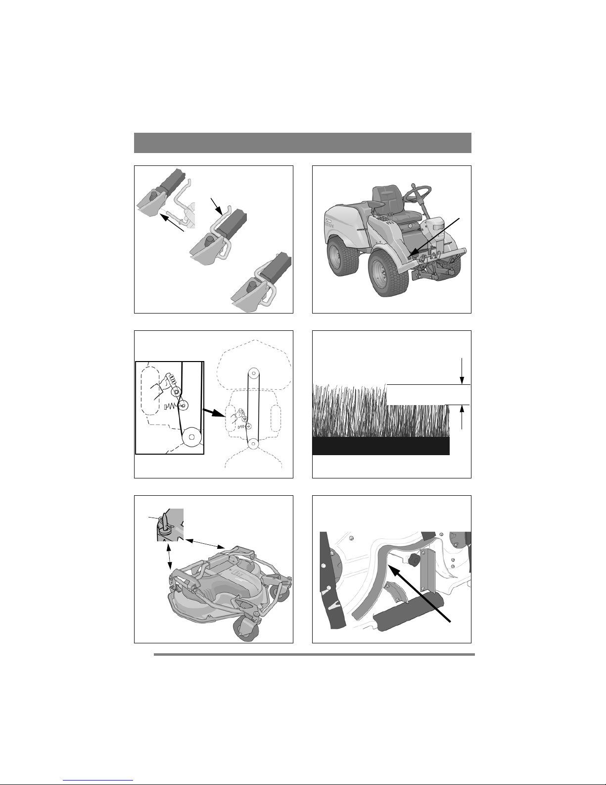
5. See fig. 1. Install the locking pins. The left locking pin is described below. The right locking pin
is installed in the same way, but mirror imaged.
• Insert the locking pin from the outside.
• Press the locking pin down over the lifting
beam.
6. Connect the cable for electric cutting height adjustment in the machine’s front right socket. See
fig. 2.
3.2 Installing the belt
The deck must be suspended on the machine before the belt is installed.
1. Set the deck in the transport position. Refer to
the machine’s instructions for use.
2. Set the maximum cutting height. Refer to the
machine’s instructions for use.
3. Place the belt around the machine’s belt pulley
at the pivot point.
4. Tension the belt with the belt tensioner. See fig.
3.
3.3 Lowering speed
Set the deck’s speed for lowering from the transport position to the working position. Refer to the
machine’s instructions for use.
3.4 Tyre pressure
Adjust the tyre pressures according to the machine’s instructions for use.
4 DISMANTLING
Remove the deck from the machine in reverse order according to installation above.
5 USING THE MACHINE
Check that the grass that is to be cut is
completely free of foreign objects such
as stones etc.
5.1 Cutting height
The best cutting results are achieved when the
when the top third of the grass is cut off. I.e. 2/3 of
the length of the grass remains. See fig. 4.
If the grass is long and has to be cut significantly,
cut twice using different cutting heights.
Do not use the lowest cutting heights if the lawn
surface is uneven. This would entail a risk of the
blades being damaged against the surface and the
lawn’s top layer of soil being removed.
5.2 Incline
In order for the cutting deck to cut optimally, the
correct incline is required. The cutting deck’s rear
section can be adjusted so that the deck has a greater forward incline than that provided by the basic
setting. This incline affects the cutting results as
follows.
5.2.1 Basic setting
The deck is in the basic setting when its rear edge
is 5 mm above its front edge. This means that the
deck is inclined forwards.
The deck is default set upon delivery.
When the deck is in the basic setting, the best
“Multiclip” effect and good dispersion of the cut
grass are achieved. The basic setting is recommended for normal grass.
5.2.2 Greater inclination
When the cutting deck is inclined forwards, the
“Multiclip” effect is reduced while the cut grass is
dispersed better and the capacity is increased.
Greater forward inclination is recommended for
thicker grass.
Greater forward inclination is achieved by lifting
the deck at the rear edge and installing the locking
pins (5:A) in the lower holes.
5.3 Composting/rear ejection
The deck can cut grass in two ways:
• Compost the grass into the lawn.
• Eject the grass behind the deck.
The deck is set for composting on delivery. In or-
der to eject the grass behind the deck, the plug in
fig. 6 must be removed.
Set the deck in cleaning or service position (see
6.2/6.3) in order to remove/install the plug.
Page 6

26
ENGLISH
GB
5.4 Mowing advice
In order to achieve optimum mowing results, follow the advice below:
• Cut frequently.
• Run the engine at full throttle.
• The grass should be dry.
• Use sharp blades.
• Keep the underside of the cutting deck clean.
6 MAINTENANCE
6.1 Preparation
All service and all maintenance must be carried out
on a stationary machine with the engine switched
off.
Prevent the machine from rolling by always applying the parking brake.
Stop the engine.
Prevent unintentional starting of the
engine by removing the ignition key.
6.2 Washing position
It is absolutely forbidden to start the
engine when the deck is in the cleaning
position.
1. Activate the parking brake.
2. Set the deck in the transport position.
3. Set the maximum cutting height.
4. Stop the engine
5. Remove both pins (5:A) and remove any washers.
6. Slacken off the belt tensioner and unhook the
belt from the machine’s pulley. See fig. 3.
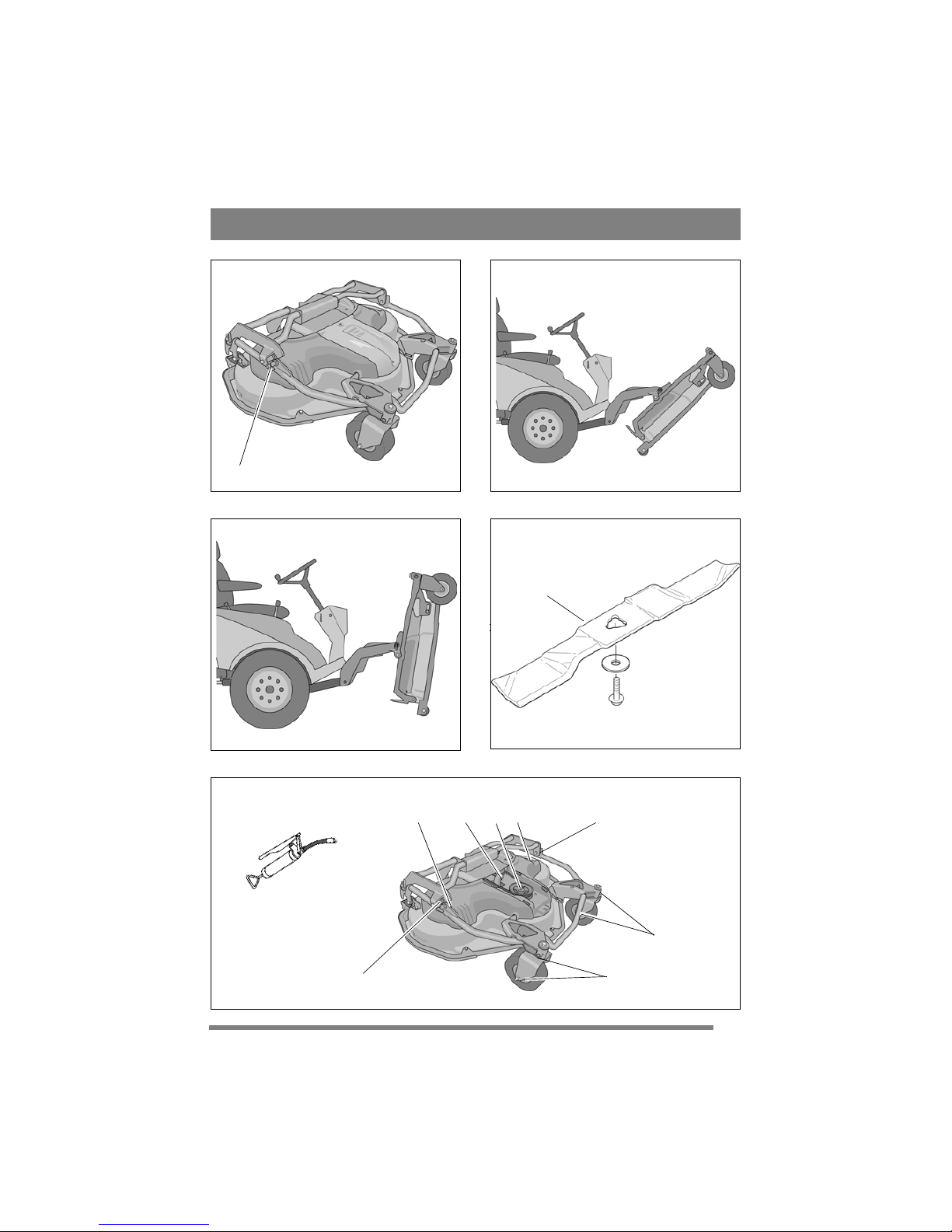
7. Set the catch (7:C) to the rear position so that it
can lock.
8. Grip the front edge of the deck and lift up until
the deck locks in the first locking position.
See fig. 8.
6.3 Service position
It is absolutely forbidden to start the
engine when the deck is in the service
position.
1. Set the deck to the cleaning position. See above.
2. Grip the front edge of the deck and lift up further until the deck locks in the second locking
position. See fig. 9.
6.4 Resetting
Two people are required to reset from the cleaning
and service position as follows:
1. Person 1 lifts the deck at the front edge so that
it releases from catch (7:C).
2. Person 2 sets the catch to the front position.
3. Person 1 carefully lowers the deck to the
ground.
4. Other connections are made according to the
relevant section under “3”.
6.5 Cleaning
The underside of the deck must be cleaned after
each use.
Set the deck in the cleaning position.
Clean the underside of the deck thoroughly. Use
water and a brush.
When the surfaces are completely dry and clean,
touch up the paintwork. Use durable paint intended
for metal outdoors.
7 MAINTENANCE
7.1 Lubrication
Lubricate all lubrication points according to the table below.
The three cutting shafts (11:B) must be lubricated
every 100 operating hours as well as after each
clean.
Other lubrication points must be lubricated every
250 hours of operation.
Use a grease gun, filled with universal grease for
the grease nipples. Pump until grease protrudes.
The lubrication points are shown in fig. 11.
Object Lubrication nipples
/ action
Figure
Bearing, belt tensioner
1 lubrication nipple 11:A
Cutting shafts 3 lubrication nipples 11:B
Bearings, link
wheel
4 lubrication nipples 11:C
Bearing on right
and left sides
2 lubrication nipples. 11:D
Page 7

27
ENGLISH
GB
7.2 Replacing blades (10:P)
Wear protective gloves when changing
blade(s) to avoid cutting yourself.
Check that the blades are always sharp. This produces the best cutting results.
Always check the blade(s) after a collision. If the
blade system has been damaged, defective parts
should be replaced.
Always use genuine spare parts. Nongenuine spare parts can entail a risk of
injury, even if they fit the machine.
Install the new blade with the punched text facing
down.
Tightening torque: 45 Nm.
7.3 Wear protection
There are two wear protection devices on the underside of the cutting deck to protect it. These can
be replaced if necessary.
8 SPARE PARTS
STIGA genuine spare parts and accessories are designed specifically for STIGA machines. Please
note that ‘non-genuine’ spare parts and accessories
have not been checked or approved by STIGA:
The use of such parts and accessories
can affect the function and safety of the
machine. STIGA accepts no responsibility for damage or injuries caused by
such products.
9 DESIGN REGISTRATION
This product or parts thereof is covered by the following design registration:
Sweden: 66 166
Germany: 499 11 740.9
France: 577 251-253, 577 439-443
USA: 435 564
GGP reserves the right to make alterations to the
product without prior notification.
 Loading...