

Page 1

STIGA PARK
110 S
8211-3009-06
Page 2
1.
2.
F
G
H
3.
4.
Page 3

SYMBOLS
ENGLISH
3. Slide in the attachment'sfixing arms into the machine's attachment brackets.
GB
The following symbols are displayed on the machine in order to remind you about the safety precautions and attention necessary when using the
machine.
The symbols mean:
Warning!
Read the instructionbook and safetymanual before using the machine.
Warning!
Do not put hands or feet under the cover of
the machine when it is running.
Warning!
Bewareof objects being flung out. Keep
spectators away.
Beforestartingany repair work,remove the
spark plug cable from the spark plug.
4. Setthe v-belt onthe machine's central belt pulley
F(fig3).
5. The tension roller G should rest on the left-hand
side of the v-belt, seen from the driver's seat (fig 3).
6. Now pull the mower deck forwards so that the
holes in the fixing arms correspond with the holes
on the attachment brackets.
7. Insertthe screws and tighten.
8a. Park -1999:
Hook the tension roller spring H into the floor on
the right-hand side (fig 3).
8b. Park 2000Hook the tension roller spring H into the fastener,
just behind the front right wheel (fig 3).
9. Lift up the mower deck and hook the chain into
the attachment lifter.
Whenchangingthe v-beltor dismantlingthemower
deck follow the above procedures in the reverse order.
PREPARATION
If this clipping unit is used with the Park model,
the number of revolutions per minute should be reduced slightly in order to comply with the current
regulations for approved noise levels:
- Senator and President models: reduce to 3,000
rpm
- Royal, Pro 16, Pro 18 and Pro 20 models: reduce to 3,200 rpm
Thisadjustment torpmshould onlybe made bythe
retaileror atanauthorised workshop,i.e. bypeople
who have the correct skills and equipment.
ASSEMBLY
MOWER DECK
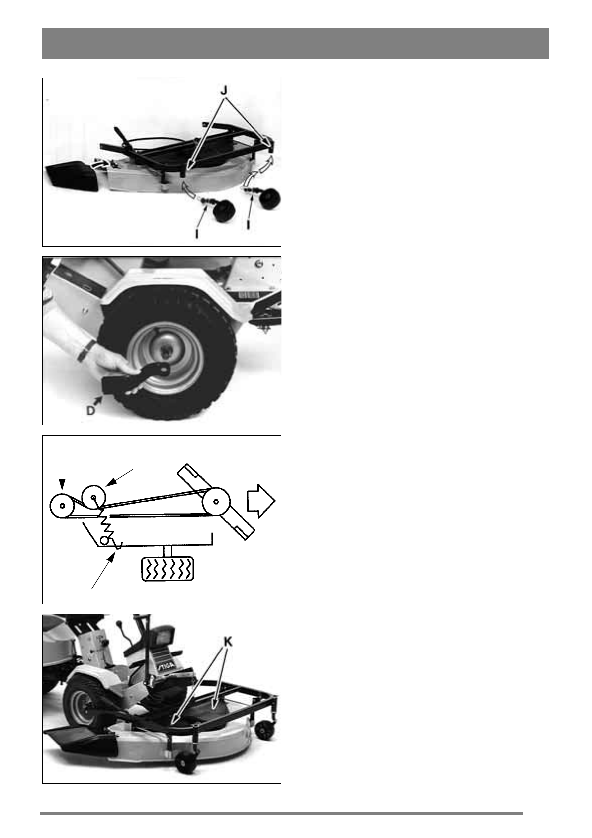
1. Fit the support wheels and the deflector as show
in figure 1.
2. Fit the attachment brackets D on the front axle
studsby usingthe washers and lockingclips (fig 2).
SETTING
1. Check that the tyreshavethe correct air pressure.
Front:0,6 bar (9 psi).
Rear: 0,4 bar (6 psi).
2. To obtain an even cut from the mower deck its
forward and rear edges must be parallel to the
ground.
- Check this by placing the machine on a flat surface.
- If adjustmentis required,adjust usingthe washers
I at the support wheels (fig 1).
Points 1 and 2 must be carried out for the mower
deck to mow evenly.
USE
MOWING HEIGHT
Themowerdeckhas17fixed mowingheights,from
30 mm to 80 mm.
N.B. The stated mowing heights apply when the
machine is standing on firm ground.
Page 4

GB
ENGLISH
MOWING HINTS
For the best effect follow this advice:
- mow regularly
- use full throttle on the engine.
- keep the underside of the mower deck clean.
- use sharp blades.
- do not mow wet grass.
MAINTENANCE
No service work to the engine or mower
deck is to be carried out unless the following action has been taken:
- the engine has been stopped.
- the ignition key has been removed.
- the ignition cable has been removed
from the spark plug.
- the parking brake is engaged.
- the mower deck has been disengaged.
CLEANING
off the v-belt from the central belt pulley.
5. Change thedamagedv-belt. Always use anoriginal v-belt. The tension roller G should rest to the
left of the v-belt as seen from the driver's seat
(fig 3).
6. Fit the screws K (fig 4).
7. Fit the mower deck in the machine's attachment
brackets.
8a. Park -1999:
Hook the tension roller spring H into the floor on
the right-hand side (fig 3).
8b. Park 2000Hook the tension roller spring H into the fastener,
just behind the front right wheel (fig 3).
REPLACEMENT OF THE DRIVE
BELT IN THE MOWER DECK
1. Remove the screws K and remove the transmission casing (fig 4).
Rinse off the underside of the mower deck casing
with a garden hose after using the mower.
If grass has dried onto the casing dismantle the
mower deck and scrape the underside clean.
If necessary, to improve the underside it can be
painted to prevent rust.
Do not spray with high pressure water
against the bearing housings on top of
the mower deck when the transmission
cover isremoved.Otherwisewater may
penetrate the bearings.
LUBRICATION
The attachment's support wheels are fitted with
two grease nipples J (fig 1). Lubricate using a universal grease periodically during the season.
Grease other moving parts too.
REPLACEMENT OF DRIVE BELT
CENTRAL BELT PULLEY - MOWER
DECK
2. Loosenthe spring whichholds the tension roller.
3. Change the v-belt and replace in the reverse order. Always use original v-belts.
BLADES
Use protective gloves to prevent cuts
when changing blades/blade tips.
Make sure the blades are always sharp. This gives
the best cutting results.
SHARPENING
For safety reasons the blades must not be sharpened on an emery wheel. Incorrect sharpening ( =
high temperature) can result in the blades becoming brittle.
When the blades are due to be sharpened, the wet
grindingmethod with awaterstone or grindstoneis
to be used.
Following sharpening, the blades must
be balanced to avoid vibration damage.
1. Unhook the tension roller spring H.
2. Remove the mower deck from the machine.
3. Unscrew the screws K and remove the transmis-
sioncasing(fig4).
4. Slide in the unit towards the machine and pull
CHANGING BLADES
Always useoriginal spare parts whenchangingthe
blades, blade attachments or bolts.
Page 5

ENGLISH
Always use original spare parts. Using
non-original spare parts can result in
the risk of damage even if they fit in the
machine.
When changing the blades, the blades central bolt
should also be replaced. It is provided with a locking device. The blade bolts torque: 65 Nm.
SPARE PARTS
STIGA original spare parts and accessories are
constructed exclusively for STIGA machines.
Note that non original spare parts and accessories
have not been checked or approved by STIGA:
Usage of such parts and accessories can
influence the machines operability and
safety. STIGA cannot be held responsible for injuries caused by these products.
GB
STIGA reserves the right to modify thee productwithout prior notice.
 Loading...