

Page 1

STIGA VILLA
107M
8211-3038-01
Page 2
1.
2.
A
C
B
3.
5.
4.
6.
A+5
A
B+5
B
7.
8.
2
Page 3

9.
10.
RL
11.
12a.
R
W
L
Z
X
Y
V
12b
Z
X
Y
V
W
13.
3
Page 4

ENGLISH
GB
SYMBOLS
The following symbols are displayed on the machine to remind you of the care and attention required when using the machine.
The symbols mean:
Warning!
Read the instruction book and safetymanual before using the machine.
Warning!
Do not place your hands or feet under the
cover when the machine is running.
Warning!
Beware of objects being flung out. Keep
spectators away.
Warning!
Before starting repair work, remove the
spark plug lead from the spark plug.
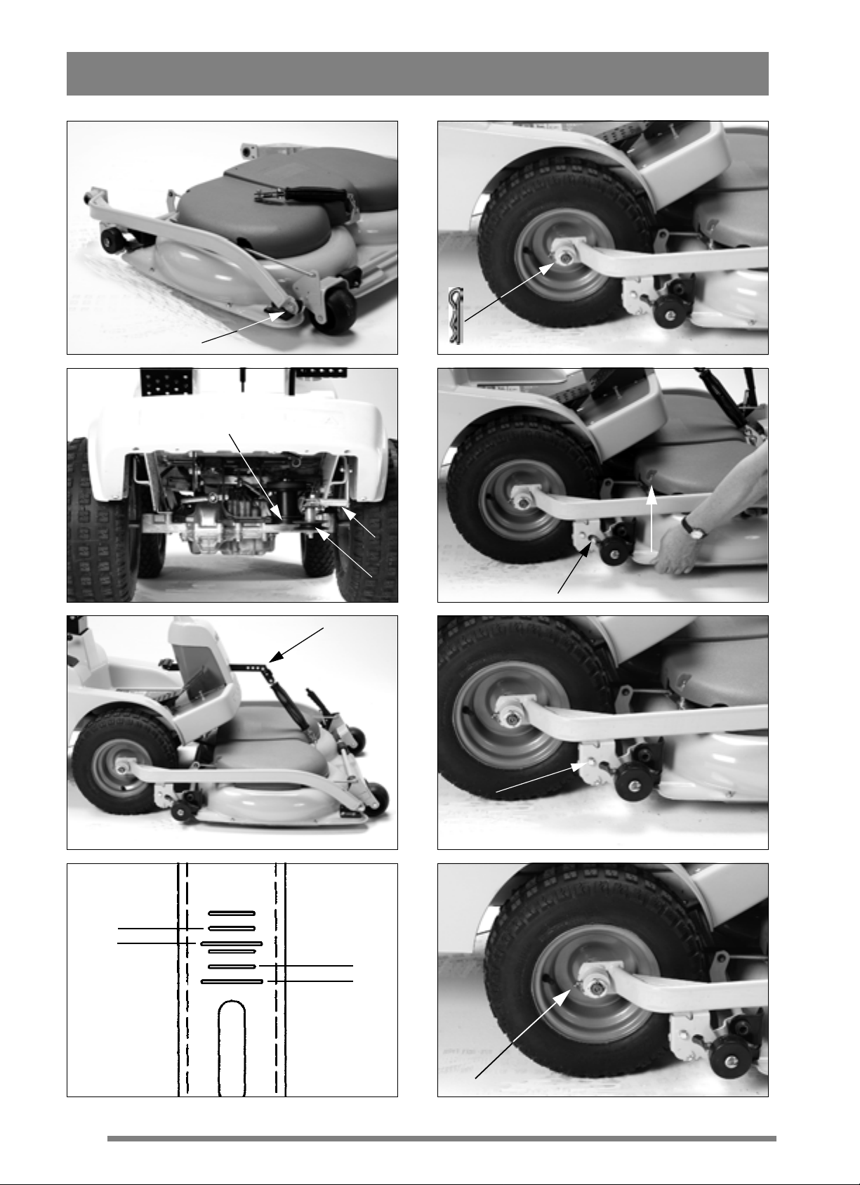
ASSEMBLY
MOWERDECKARMS
1. Fittheleftand right mower deck arms in the two
front corners of the mower deck. Use the existing
bolts and washers (fig. 1). Tighten the bolts. After
tightening,it shouldbepossibletomove the mover
deck arms up and down.
2. Do not hook on the rear part of the arms on the
mower deck y et (s ee “Mower deck” item 7 below).
MOWER DECK
1. Place the mower deck in front of the machine.
Set in the maximum mowing height.
2. Remove the locking pin and the outer washer
from the machine’s front spindle.
3. Thread one of the arms on the front spindle.
Place the washer on the spindle and lock with the
locking pin. Do the same on the other side (fig. 2).
the belt and pull outwards to the left (see from the
driver’s position).
6. Hook on the tensioning pulley spring C in the attachment (fig. 3).
7. Lift up the rear end of the mower deck past the
catch,until it drops down. When the weight of the
mower deck rests on the topside of the catch it is
correctly fitted (fig. 4).
8. Screw tight the lifting spring in the machine’s
lifting arm (fig. 5).
ADJUSTMENT
The mower deck must be correctly adjusted if is to
mow well.
1. Make sure that the tyres have the correct air
pressure:
Front: 0.4 bar (6 psi).
Rear: 0.6 bar (9 psi).
2. Place the machine on a level surface. Unscrew
the bolts on both sides of the deck (fig. 6).
3. On the side of the mower deck arms there are
four short and two long marks. The upper long
mark (A) is the basic setting for a machine with
16” tyres. The lower mark (B) is for a machine
with 17” tyres (fig. 7).
Note. Villa has 16” wheels.
Themower deck can be adjusted in different ways,
depending on the length of the grass:
4a. Mowing of normally l ong grass:
Adjust the deck so that the front and rear edges are
atthesame height over t he ground.UsepositionA.
This position gives the best “Multi-mowing effect”, i.e. the g rass is shredded best.
4b. Mowing of long grass:
Adjust the deck so that th e rear edge comes higher
up than the front edge. Use position A+5. This position allows the deck to throw out the grass more
easily at the rear edge.
5. Tighten the bolts well after adjusting.
USING THE MACHINE
4.Workon the V-belt on the machinepulleyA (fig.
3).
5. Tension the belt with the tensioning pulley B.
The tensioning pulley should lie on the inside of
MOWING HEIGHT
The mowing height can be varied in several fixed
positions,from30to75mm.
5
Page 5

GB
ENGLISH
Note. The given mowing heights apply when the
machine is standing o n a firm surface.
MOWING TIPS
Follow these tips for the best“Multi-mowing effect”:
- mow frequentl y.
- use the engine at full throttle.
- keep the underside of the mower deck clean.
- use sharp blades.
- do not mow wet grass.
- mow twice (with different mowing heights)
if the grass is long.
SERVICE AND MAINTENANCE
PREPARATIONS
Unless otherwise stated, all service and maintenance should be performed when the machine is
stationary and with the engine switched off.
Alwaysapply the parking braketo prevent the machine from rolling.
To prevent starting the engine involuntarily,alwaysrelease thespark plug lead
from the spark plug and earth it. Remove the minus lead from the battery .
LUBRICATION
The mower deck arms are equipped with grease
nipples (fig. 8).
Lubricate these after every 25 hours of operation
(or at least once per season) with universal grease.
MAINTENANCE TIPS
T o simplify cleaning and maintenance the mower
deck can be lifted up:
When the deck is lowered to working position,
make sure that the catch drops into position when
the rear end of the deck has been lifted up (fig. 4).
CLEANING
The underside of the mower deck should be rinsed
down each time it has been used.
Scrape the underside clean if dry grasshas stuck to it.
If necessary, touch-up th e underside with paint to
prevent rust.
BLADES
Use protective gloves when replacing
the blades to avoid injury.
Make sure that the blades are always sharp. This
gives the best mowing results.
Alwayscheckthebladesaftermowing.Iftheblade
system is damaged, replace defective blades.
Always use original spare parts. Nonoriginal spare parts can result in damage even if they fit on the machine.
Theblades rotatein opposite directions.
This implies that there is a right blade
and a left blade. When replacing the
blades, make sure that they are fitted
correctly.
Fit the blades accordin g to diagram 11, where the
blade edges are marked. The raised edge of the
blade must be positioned facing inwards to the
blade attachment.
The mowing system consists of two blade members with two replaceable blades Y (fig. 12). Both
blades must be replaced at the same time to av oi d
imbalance.
1. Adjust the mowing height setting to the maxi-
mum mowing height.
2. Lift the rear end of thedeck with one hand (fig. 9).
3. Poke up the catch and release do wn the rear edge
of the deck (fig. 9).
4. Repeat this procedure on the other side.
5. Unhook the tensioning pulley spring (fig. 3).
6. Work off the belt from the machine pulley.
7. Lift up the deck to vertical position (fig. 10).
6
Fitthenew blades.TightentheboltsV andW well.
Tightening torque: V - 9.8 Nm, W - 24 Nm.
A powerful collision can bend out the blades. Release the locking nut X and bend back the blade.
Fit a new original bolt V. Tighten the locking nuts
XandZ.
POSITIVE DRIVE BELT
The two blades inside the deck are driven by a positive drive belt.
Page 6

ENGLISH
If one of the blades hits asolid object (e.g. a stone),
this can alter the belt tension. This can result in the
positive drive belt “cogging over”, which in time
can damage the blades.
Always check after a powerful collision
that the two blades are at right-angles
to each other (fig. 11).
The working areas of the two blades overlap each
other. If the relative positions of the blades have
changed there is a severe risk that they will knock
against each other. This will result in severe damage to the mower deck.
If this is the case, hand in the machine with mower
deck to a service workshop forrepair and overhaul.
SPARE PARTS
STIGA original spare parts and accessories are
specially designed for STIGA machines. Note that
“non-original” spare parts and accessories have
not been checked or approved by STIGA.
GB
Theuse ofsuchparts andaccessoriescan
affect the functioningand safety of the
machine. STIGA cannot accept liability
for damage caused by such products.
ACCESSORIES
The mower deck can be fitted with support rollers
in the front corners when mowing close to house
foundations andgarden wallsto provide protection
from damage (fig. 13).
PATENT – PROTECTION OF DE-
SIGNS
This machine, or parts thereof, is protected by the
following patents and protection of designs:
9902299-8 (SE), SE/00/01222 (PCT)
99 1161 (SE), 499 11 740.9 (DE), M1990 000734
(IT), 577 439-443 (FR), 115326 (US)
STIGA reserves the right to modify the product without
giving any prior notice.
7
 Loading...