

Stierius VARIO 5, EG 30-60 II EPC, VARIO 5-20, EG 30-60 II EPC PRO, VARIO 5-20 PRO Operating Instructions Manual

Bedienungsanleitung
Operating Instructions
Mode d'emploi
Istruzioni per l'uso
Bremsen - Service - Geräte
VARIO 5
VARIO 20 II
VARIO 20 II PRO
EG 30-60 EPC
EG 30-60 EPC PRO

General safety notes
GB
1. The unit may only be connected to a power supply with voltage, current type and
frequency matching the specification on the type plate! Never pull the power plug
on the cord when unplugging it!
2. Do not start operation of the unit if the power cord has been damaged or the
housing or the pressure hose shows sign of damage.
3. Never connect the unit to compressed air!
4. Operate only wirh pure brake fluid on glycol base (DOT 3, DOT 4, DOT 5.1).
Products containing mineral oil will destroy the unit!
5. Before corrective maintenance, cleaning or repairs on electric devices, the user
must ensure that the device is without current, i. e. switched off and the power plug
pulled and the brake fluid has been drained from the unit.
6. Repairs may only be performed by trained professionals with corresponding shop
equipment.
7. Improper repair or handling may lead to significant hazards to the user and may
damage the unit. Unintended use or improper operation of the unit will void the
liability for possible damages.
8. A function and leakage check must be performed after the repair of the unit has
been completed. It must be ensured herby that units for brake fluids are only
operated with brake fluid on glycol base (DOT 3, DOT 4, DOT 5.1). The use of
brake fluids not recommended will lead to the destruction of the unit.
9. Do not put oil, or gasoline, soaked rags on the bleeder unit because of fire hazard.
15

General Information
GB
The new STIERIUS Brake Bleeding Unit uses the latest technical advances in
bleeding and filling hydraulic brake systems. One man is all it takes to
operate and perform a complete brake bleeding service. Designed for all brakeand hydraulic clutch systems.
This unit is built extremely well for industrial and shop use. It is universal
and can be used in many different applications. Any technician using our unit
will appreciate the value and ease of use.
Every device is subject to special tests and certification.
Therefore every unit does conform to the EEC-Guidelines. Certificates are available on
request.
Important!
Brake fluid which is contaminated with dirt or water can cause the brake
system to fail. It is recommended to use only brake fluid from its original
container.
The hygroscopic properties of brake fluid cause it to draw and take in
moisture from the air. This dangerously reduces the boiling point of the brake
fluid.
The heat generated by the brake system with moisture in the brake fluid,
causes steam bubbles to collect. This reduces the function and in extreme
cases can eliminate the effectiveness of the brakes all together.
Corrosion such as electrolosis is caused inside of brake systems with brake
fluid containing moisture.
The steam bubbles in the brake fluid carry in themselves oxygen which causes
oxidation an corrosion of the brake system.
It is therefore recommended to replace the old brake fluid with new fluid
annually or every 15,000 km.
By pressure bleeding the hydraulic brake system, the new fluid flushes the old
out of the system leaving you with the most thorough bleed available.
16

Delivery Status / Installation / Operation start-up
GB
The packing will contain the following parts at the delivery status:
1 Control Assy. (incl. Pressure hose and Power cord)
1 Chassis
4 Mounting Screws
1 Suction tube assy.
1 Adapter no. 20
1 Recovery bottle (only PRO)
Please check the unit after unpacking for any transportation damage.
Transport damages should be immediately reported to the responsable carrier!
Part Part Description Part Part Description
1 Control assy. 11 Suction tube assy.
2 Pressure hose 12 Sealing cone
3 Pressure hose coupler 13 Unmistakeable nipple for suktion tube
4 Power cord 14 Coupler for suktion tube
5 ON/OFF-Switch 15 Connection low fluid indicator
6 Fuse 16 Container security barr
7 Low fluid level indicator 17 Wheel with cap
8 Self purging nipple 18 Caster cpl.
9 Pressure regulator EPC: Button +/- 19 Adapter No. 20
10 Gauge
PRO-Version:
21 Spiral hose 23 Recovery bottle
22 Pipet 24 Recovery bottle hose
Corrective maintenance / Repair
Corrective maintenance and repair at the unit may only be performed by expert
personal!
The device is designed so in case of any defect only the control assy. must be sent in
for inspection.
In this case:
The mounting screws on the left and right panel must be unscrewed.
Take down the control assy. incl. filling hose and power cord from the chassis.
17

Technical Data VARIO 5:
GB
H x W x D: 460 x 300 x 320 mm Power supply: AC 230 V / 50/60 Hz
Capacity: 5 l Output E.-Motor: 120 W
Pressure hose lenght: ca. 3,5 m Electrical fuse M2,0A (5x20 mm)
Length of power cord: ca. 4,5 m Reg. pressure range: 0-3,5 bar adjustable
Empty weight: 10 kg Low fluid level shut off: Yes
Temp.-work area: 0°C - +45°C Pressure gage: 0-4 bar (0-86 psi)
Technical changes, including engineering changes, remain expressly reserved!
Technical Data VARIO 5-20 and VARIO 5-20 PRO:
H x W x D: 850 x 400 x 330 mm Power supply: AC 230 V / 50/60 Hz
Capacity: 5 – 20 l Output E.-Motor: 120 W
Pressure hose lenght: ca. 3,5 m Electrical fuse M2,0A (5x20 mm)
Length of power cord: ca. 4,5 m Reg. pressure range: 0-3,5 bar adjustable
Empty weight: 23 kg Low fluid level shut off: Yes
Temp.-work area: 0°C - +45°C Pressure gage: 0-6 bar (0-86 psi)
Technical changes, including engineering changes, remain expressly reserved!
Technical Data EG 30-60 II EPC and EG 30-60 II EPC PRO:
H x W x D: 920 x 450 x 560 mm Power supply: AC 230 V / 50/60 Hz
Capacity: 30 – 60 l Output E.-Motor: 230 W
Pressure hose lenght: ca. 3,5 m Electrical fuse M2,0A (5x20 mm)
Length of power cord: ca. 4,5 m Reg. pressure range: 0-3,5 bar adjustable
Empty weight: 33 kg Low fluid level shut off: Yes
Fluid flow: ca. 40 l/h Pressure gage: 0,5-6 bar (0-86 psi)
(at 2,5bar dynamic/2,0bar flow) Temp.-work area: 0°C - +45°C
Technical changes, including engineering changes, remain expressly reserved!
18

Operating Instructions:
GB
1. Place a new brake fluid container on the fluid can holding platform. Next secure the
hold down chain to prevent can from slipping (16).
2. Remove the large container opening and place the fluid pick-up tube (11) into the
opening. Be sure to press the seal cone (12) against the opening of the container.
3. Connect the quick coupler (3) of the pressure hose (2) to the self purging nipple (8).
4. Plug the power cord (4) of the unit into the proper wall outlet. (230V AC, 0,1kW,
50Hz)
5. To insure an air free bleed run the unit for at least 30 seconds with the quick
coupler (3) of the pressure hose (2) connected to the self purge nipple (8). This
purges the air from the hose and the pump. This procedure should be performed
before every bleed job. When the unit is well purged, turn the unit off (5) and
remove the quick coupling (3) from the nipple (8). The unit is now ready to use.
6. Connect the quick coupler (3) of the pressure hose (2) to a properly installed
master cylinder adapter.
7. Turn the power switch (5) to the ON position. The green switch light should be
illuminated.
8. Adjust the bleeding pressure by turning the pressure regulator knob (9) to the
recommended pressure by the vehicle manufacturer. The bleeding can now begin.
According to the vehicle manufactures procedure, bleed the system. These
instructions are to be specifically followed when working on ABS systems.
9. Before removing the pressure hose (2) from the master cylinder adapter, relieve
the pressure by switching the unit off (5). Return the original master cylinder cover
back onto the master cylinder reservoir.
19

General Information
GB
In the case the brake / clutch pedal becomes soft or the operation activity of the brake /
clutch pedal is to long it is needed to vigorously pump the pedal and repeat
the bleeding procedure again.
Adjusting the proper bleeding pressure
The pressure is adjusted at the factory to 2 bar. This guarantees that master
cylinder reservoirs are not warped or deformed with too much pressure. This
also keeps the outer boots or dust seals from leaking.
In case less pressure is required to bleed certain systems, turn the
hand knob CCW to decrease pressure. In case higher pressure is required,
the pressure can be increased by turning the pressure regulator knob CW to the
desired pressure.
Attention!
After changing the pressure adjustment of the bleeding unit, readjust it back
to the factory setting of 2 bar.
Feature: Pre-suction system (PRO version only)
Recovery bottle (23) must be connected to the nipple of the rear panel.
Turn On/OFF-Switch (5) to suction position.
Use the pipet (22) to extract the old brake fluid from the master cylinder reservoir. Clip
the pipet back to the fitting on the rear panel.
Turn the unit off (ON/OFF-Switch (5) in position 0)
Refill the master cylinder reservoir with fresh brake fluid (according to the manufactures
recommendation).
Please follow the steps shown under „Operation instructions“.
The pre-suction system of the PRO version may not be used for the transfer of
any other fluids!
ONLY FOR BRAKE FLUID!
Failure to observe any deleted warranty claim.
20

Note
GB
If the device is switched on and still shows no function, the power supply may be
interrupted. Please check the fuse (6) and exchange it if needed (please see “Technical
Data”).
To reduce the pressure inside the unit it is necessary to turn off the unit on the ON/OFF
switch (5). Turn the pressure regulator knob CCW totally. Turn on the unit with the
ON/Off switch (5). Now you can adjust the fluid pressure independently by turning the
pressure regulator knob CW.
Important:
After bleeding the brake system with a lower or higher pressure than 2 bar, the
pressure regulator must be reset to 2 bar!
When does the unit needs to be refilled?
After reaching a low level of brake fluid inside the container, the unit will shut off the
motor + pump automatically. This will ensure that no air will reach the brake system at
all.
As an additional control feature an acoustic warning signal and control lamp (7) lights
up.
In this case, the empty brake fluid container must be exchanged for a full one. For this
the unit should be turned off on the ON/OFF switch (5). Please continue the procedure
according to the heading “Operation start-up”.
Disposal
The unit is to be returned to your sales partner or be disposed off in compliance with
the legal and official waste regulations.
21

Practical Tips for bleeding and servicing
GB
hydraulic brake and clutch systems
It is recommended to use the proper master cylinder adapter with the unit before
beginning your bleeding jobs.
Allow the brake cylinder bleeding nipple to remain open until the fluid
becomes clear, and free of air before tightening.
To maintain a more accurate invoicing control and cleanliness, we recommend
using our specially designed retrieval bottle. The bottle is equipped with a
flexible hose and a metered bottle to determine the amount of brake fluid
used. This is to assist you in determining the cost of brake fluid in the
bleeding job.
In an initial brake system fill it is recommended to open all bleeder nipples
at once to insure the complete purging of air. This allows the air to flow out
in accord to the shortest path and least resistance. This also prevents the
mixing of residual brake fluid still in the system. As the brake fluid begins
to flow evenly and cleanly, the nipples can be hand tightened one at a time in
the correct order and then tightened properly with a wrench.
During bleeding process we recommend that the pedal be pressed a few times to
flush the primary and secondary chambers of the master cylinder. This flushes the dirt
and air from the master cylinder.
In bleeding brake calipers it is recommended to note that they require a
larger amount of brake fluid to completely flush them out. Some of the brake
fluid in the caliper may not be in line with the direct flow of the brake
fluid. This is why some manufactures have installed more that one brake bleed
nipple in the caliper. Please look for additional nipples and use them
alternately in flushing out the caliper.
Some vehicles come with load sensitive brakes. It may be necessary to jack up
the rear end, placing it at a certain level in order to activate the valve for
the rear brakes. Please refer to your manufacture shop manual for proper
bleeding instructions.
In bleeding and flushing some clutch systems, it is recommended to use our #67
bleeder hose. It seals itself on the bleed nipple and allows pressure to be
introduced into the bleed nipple of the slave cylinder. You can then reduce
the fluid level of the master cylinder reservoir with a suction hose.
Please take note to our adapter application list:
www.stierius.com!
22
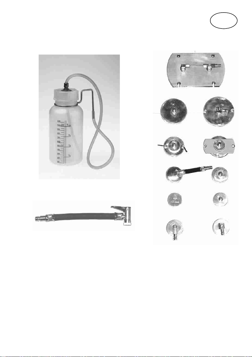
Accessories:
GB
Recovery Bottle (Part-No. 3-0070)
Reverse Bleeder Hose No. 67
(Part-No. 3-0069)
Various adapters
Please take note to our adapter application list:
www.stierius.com!
23

Bodo Stier
Hydrotechnik GmbH
Gutenbergstr. 2-4
D-78727 Oberndorf /Neckar
Telefon +49 (0)7423 3321
+49 (0)7423 4711 (Technische Hotline)
Fax +49 (0)7423 82422
Internet: http://www.stierius.com
Email : service@stierius.de
42
 Loading...