

Page 1

Version: 2016-12-05 251937_V2
Instruction Manual
Care bed
Libra
Page 2
Instruction Manual for Care Bed Libra
Page 2 -
Care bed Libra
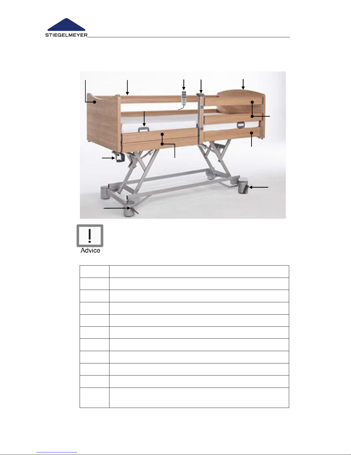
In this instruction manual, the numbers or letters which
appear in bold face and round brackets () are referring
to the care bed’s operating device as shown in this
illustration and the following illustrations.
Position
Designation
1
Main footboard
2
Bar full-length safety sides (standard)
3
Handset
4
Removable centre support (optional
5
Main head end
6
Bar combined safety sides (optional)
7
Mattress restraint rail
8
Side panel
9
Middle support holder (optional)
10
Individual axle braking (standard)
Optional: Central braking - activation footboard.
Page 3
Instruction Manual for Care Bed Libra
Page 3
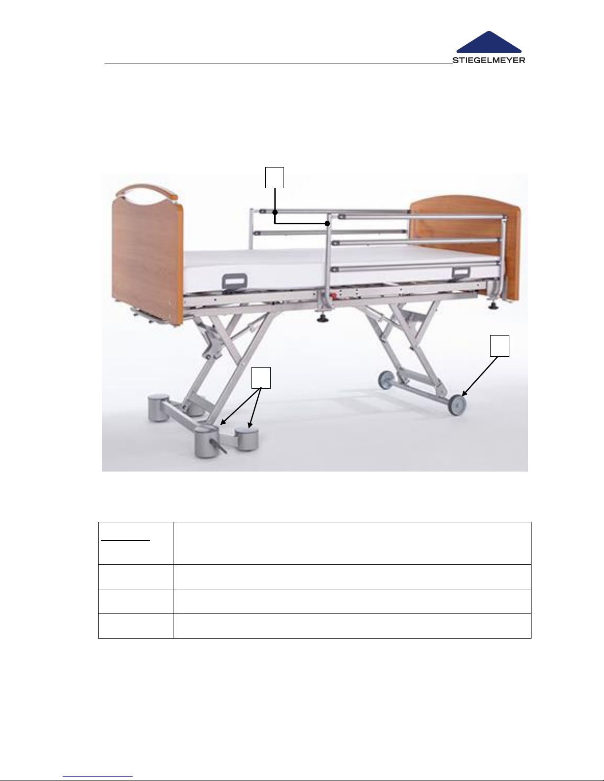
The Libra bed can be ordered in the following optional model versions:
Floor Access model version: This version has no metal supporting bars along
the long sides of the bed on the chassis.
Features:
Thanks to the high ground-clearance chassis, the lifter and
cleaning equipment can pass smoothly under the bed.
A
Pivoting safety sides (both sides)
B
Stable casters/fixed castors (head end)
C
Double castors (foot end)
A
B
c
Page 4
Instruction Manual for Care Bed Libra
Page 4 -
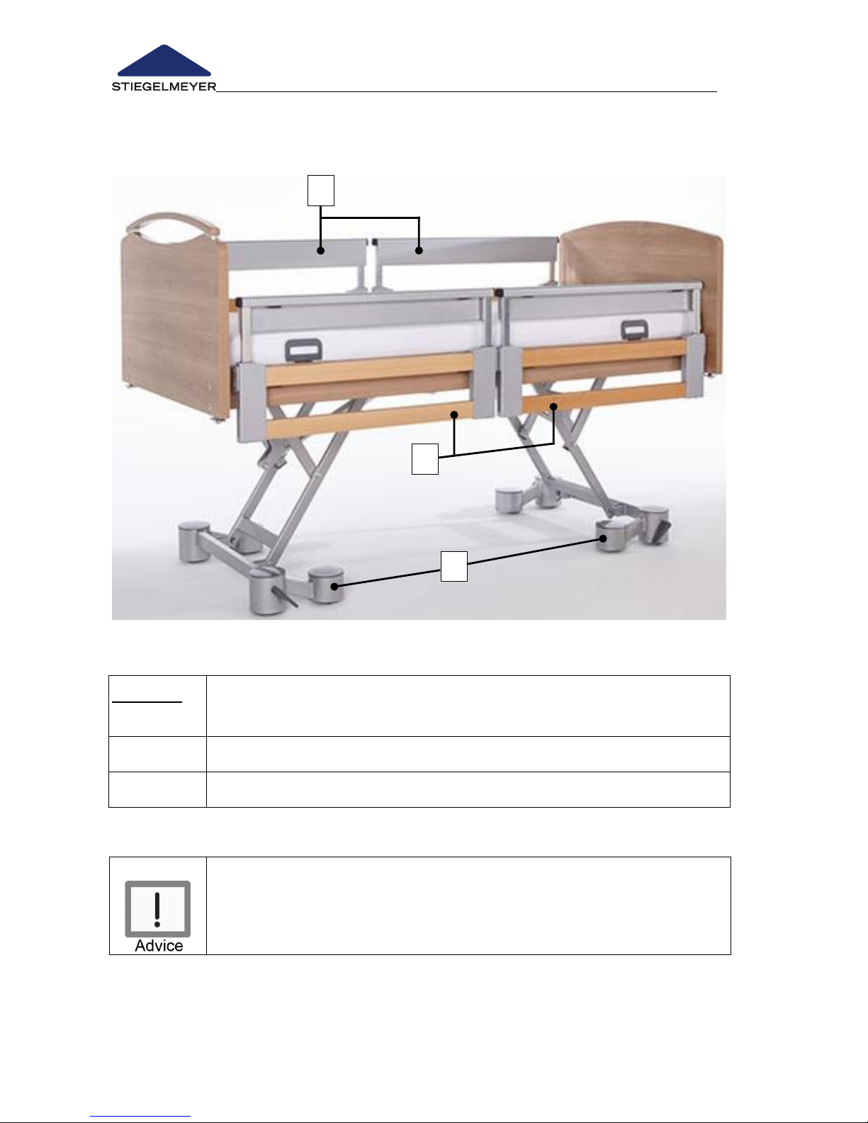
Floor Access Plus model version: This version has no metal supporting struts
along the long sides of the bed on the chassis.
Libra beds can also be supplied without safety sides. Refer to
Chapter 4.5.6 for more information about this.
Features:
Thanks to the high ground-clearance chassis, the lifter and
cleaning equipment can pass smoothly under the bed.
D
Split "MobiFlex" safety sides (both sides)
C
Double castors "easy-floor access" (head and foot ends)
D
D
C
Page 5

Instruction Manual for Care Bed Libra
Page 5
Contents
1 FOREWORD ............................................................................................................. 7
2 GENERAL INFORMATION ....................................................................................... 8
2.1 Definition of the Groups of Persons Involved............................................... 9
2.2 Safety Information ......................................................................................... 10
2.2.1 Explanation of the Safety Symbols Used ........................................... 10
2.2.2 Safety Information for the Operator .................................................. 11
2.2.3 Safety Information for the User ............................................................ 12
2.3 Product Description ....................................................................................... 14
2.3.1 Designated Use ..................................................................................... 14
2.3.2 Special bed features ............................................................................ 16
2.3.3 Optional Electrical Equipment ............................................................ 16
2.3.4 Mechanical special equipment (optional) ...................................... 16
2.3.5 Materials Used ....................................................................................... 17
2.3.6 Structural Design ................................................................................... 18
3 PUTTING INTO SERVICE ........................................................................................ 19
3.1 Checklist: Inspection by the User................................................................. 20
3.2 Location Requirements ................................................................................. 21
4 OPERATION .......................................................................................................... 22
4.1 Moving and braking the bed ...................................................................... 22
4.1.1 Individual axle braking (Standard) ..................................................... 23
4.1.2 Central braking (optional) ................................................................... 23
4.2 Mechanical adjustment options ................................................................. 24
4.2.1 Lower leg rest (LR) ................................................................................. 24
4.2.2 Manual emergency release of backrest .......................................... 25
4.2.3 Emergency release of backrest using Quick Release (optional) .. 27
4.3 Electrical Adjustment Options...................................................................... 28
4.3.1 Special Safety Information on the Electrical Drive System ............. 28
4.3.2 Handset (Standard) .............................................................................. 30
Sleep position ...................................................................................................... 30
4.3.3 Trendelenburg handset (optional) ..................................................... 32
4.3.4 Handset including Trendelenburg (optional) ................................... 33
Trendelenburg (Trendelenburg position) ........................................................ 33
4.3.5 Locking functions handset ................................................................... 34
4.3.6 Emergency release using the 9-Volt batteries .................................. 35
4.4 Attachments and Optional Equipment ..................................................... 36
4.4.1 Cable holder .......................................................................................... 36
4.4.2 LED reading lamp* ................................................................................ 37
4.4.3 Under bed lighting* ............................................................................... 38
4.4.4 Patient lifting pole * ............................................................................... 39
4.4.5 Grab handle* (triangular handle) ...................................................... 40
4.4.6 Infusion holder at foot end * ................................................................ 41
4.4.7 Bed extension * ...................................................................................... 42
4.4.8 Linen holder * ......................................................................................... 44
Page 6

Instruction Manual for Care Bed Libra
Page 6 -
4.5 Safety sides ..................................................................................................... 45
4.5.1 Full-length safety sides (standard) ...................................................... 46
4.5.2 Special Safety Information for Safety Sides ...................................... 47
4.5.3 Operation of split safety sides * .......................................................... 49
4.5.4 Swivelling safety sides * ........................................................................ 54
4.5.5 Split MobiFlex safety sides * ................................................................. 56
4.5.6 Variant - without safety side * ............................................................. 59
4.5.7 Comfort mattress base - width 90 cm * ............................................. 60
4.5.8 Comfort mattress base - width 100 cm* ............................................ 61
5 CLEANING AND DISINFECTION .......................................................................... 62
5.1 General Information on Cleaning and Disinfection ................................. 62
5.2 Cleaning and Disinfection Instructions ....................................................... 63
5.3 Instructions for the user and expert ............................................................ 64
5.4 Cleaning and Disinfection Agents .............................................................. 65
5.5 Handling Cleaning and Disinfection Agents ............................................. 67
6 MAINTENANCE .................................................................................................... 68
6.1 By the User ...................................................................................................... 69
6.2 By the Operator ............................................................................................. 70
6.3 Replacement Parts ........................................................................................ 75
6.4 Service address .............................................................................................. 75
6.5 Replacement of Electrical Components ................................................... 76
6.5.1 Plug assignment of the control unit ................................................... 76
6.5.2 Connection of a reading lamp (optional equipment) ................... 77
6.5.3 Control unit replacement .................................................................... 77
6.5.4 Motor replacement .............................................................................. 78
6.5.5 Decommissioning .................................................................................. 78
7 TROUBLESHOOTING ............................................................................................. 79
8 ACCESSORIES ...................................................................................................... 81
9 TECHNICAL DATA ................................................................................................ 82
9.1 Dimensions and Weights .............................................................................. 82
9.2 Electrical Data ............................................................................................... 82
9.3 Ambient Conditions ...................................................................................... 84
9.4 Technical Information on Electromagnetic Compatibility (EMC) ......... 85
9.5 Classification .................................................................................................. 89
10 DISPOSAL INSTRUCTIONS .................................................................................... 90
11 EC – DECLARATION OF CONFORMITY ............................................................... 91
Page 7

Foreword for private users
i
1 Foreword for private users
Dear Customer,
We would like to thank you for the purchase of our care bed designed for professional use
and for the trust you have awarded to us.
You have acquired a high quality product which is intended for long term use. Please
consider the following additional explanations as a supplement to the standard user
manual of your care bed for private use only and not for commercial use.
For Standard User
Manual, Chapter…
Explanation/ Adjustment
1 Foreword
The foreword in the user manual is going to be adjusted
according to this special foreword
2. Explanation of
named group of
persons
You are operator and user at the same time and prepare the
care bed for the actual use by the person needing care (=
resident/patient).
Consider the following additional points for beds manufactured
by the Burmeier company:
By means of video assembly instructions and use of the
instructions in the user manual you get the necessary guidance
to assemble the care bed which is delivered disassembled, and
to check it as qualified personnel without any difficulties. You will
find further details in chapter 3.
2. Safety instructions for
operators
Warning! Risk of crushing from movable parts if not assembled
according to steps provided in the assembly video and user
manual:
Non-observance can lead to serious injuries such as crushing of
limbs.
When making any adjustments, always ensure that there are
no obstructions (for example, that the patient / carer /
visiting family members limbs are not in the way, to ensure it
does not become trapped in the rests or mattress base.
This bed is no toy. Do not leave children unattended with the
bed when any electrical adjustments functions are
unlocked.
The necessity of regular inspections (annually), testing functions
and checking for damages in commercial use is omitted
according to chapter 6.
Attention: The basic safety and functional tests for you as a user
still have to conducted according to chapter 6.
Page 8

Foreword for private users
ii
For Standard User
Manual, Chapter…
Explanation/ Adjustment
Only for care beds
„Libra“ and „Venta“
2.3.1 Intended use
Enhancement: These care beds have also been developed to
be a comfortable solution for domestic care for persons in need
of care, disabled or frail people.
These beds will aid care in these environments.
3. Assembly and
commissioning
We generally recommend you to assemble the bed with two
persons, of whom one should be technically versed.
In addition to the existing version of the user manual, before
starting with the assembly process, please watch the assembly
instructions video corresponding to your care bed model:
www.stiegelmeyer-homecare.co.za/user-manuals
6. Maintenance
The legal operator standards shall not be applicable, since it is
intended solely private use. Nevertheless, we strongly
recommend you to carry out the simplified inspections for users
with the help of the checklist.
If you detect any damages during this inspection, contact our
local ASSIST Technical division for assistance on 0861 11 11 12 or
10. Disposal instructions
Disposal of electronic parts: Private users of electronic devices
shall dispose electronic parts via communal collection
according to WEEE directive 2012/19/EU. In other countries
outside of the EU the national specifications have to be
considered. Please contact your local disposal company.
Thus you have taken all necessary precautions to ensure a safe, long life operation of the
product in private and not commercial use.
For all further questions and customer service requests please contact our subsidiary:
Stiegelmeyer Africa (Pty) Ltd
The Estuaries, Century City
Cape Town, 7441
Postal: Private Bag X6, Suite 32, Panorama, 7506
Page 9

Instruction Manual for Care Bed Libra
Page 7
1 Foreword
Dear Customer,
Stiegelmeyer has built this bed to give you the best possible help in meeting
all the challenges posed by care-giving. We passionately pursue the goal of
developing products that are of a high-quality and durable. Our beds should
make staying in bed as pleasant and as safe as possible for patients and
residents also ease the work of the care staff. For this reason, all functions and
electrical safety are tested prior to delivery. Each bed leaves our factory in
perfect condition.
Correct operation and care are necessary to ensure the bed is kept in this
excellent condition over the long-term. Therefore, please read and observe
these instructions carefully. It will help you to put the bed into service for the
first time and to use it on a daily basis. The instruction manual contains all
necessary information to ensure ease of operation and safe handling of this
bed, both for you as the operator and for your users. It is a practical reference
guide and should be kept close to hand at all times.
Even after purchasing a bed, Stiegelmeyer is still on hand to help at any time.
Our Assist business division can provide you with customised solutions in all
matters relating to inspection and maintenance, repair and process
optimisation. You can reach our customer care centre in Germany by phone
at +49 (0) 5221 185 - 777. Customers outside Germany can contact our sales
distributors in the respective country if they have any questions. Contact
details can be found on our website www.stiegelmeyer.com.
We wish you and your users every success and satisfaction with the care of
your patients and residents.
Stiegelmeyer GmbH & Co. KG
Disclaimer
This product is not licensed for use on the North American market. This applies
particularly to the United States of America. The distribution and use of the
care bed in these markets, including via third parties, is forbidden by the
manufacturer.
Page 10
Instruction Manual for Care Bed Libra
Page 8 -
2 General Information
The Libra care bed is simply referred to as the 'bed' or 'care bed' in
the following. This instruction manual describes the optional
functions and special equipment for the bed in addition to the
standard functions which might not apply to the model that you
have selected.
This care bed fulfils all the requirements of the 93/42/EEC directive for
medical products. It is classified as a class 1 active medical device in
accordance with the Medizinproduktegesetz (German abbreviation: MPG
§ 13, Medical Devices Act).
Please also pay attention to your obligations as the operator in
accordance with the MPBetreibV (Medical Devices Operator Ordinance),
in order to ensure permanently safe operation of this medical product with
no risk of danger to occupants, users and third parties.
This instruction manual contains safety information which must be followed.
All users working on and with the care bed must be familiar with the
contents of this instruction manual and follow the safety advice provided.
Instructions for the Operator:
Any item of technical equipment, electrical or otherwise, can prove
hazardous if operated improperly.
Please instruct users in the proper use of this care bed in accordance with
MPBetreibV Section 5 (Medical Devices Operator Ordinance).
Ensure that users know where this instruction manual is kept, in accordance
with the Medical Devices Operator Ordinance (MPBetreibV) Section 9.
Before putting the bed into service for the first time:
Remove all transport securing devices and packaging film.
Clean and disinfect the hospital bed prior to first-time use.
Bed features
The main features of the Libra bed are listed here below:
Model
Height
adjustment
range
Safe
working
load
Type of castor
Castor locking
mechanism
Libra
approx. 26 -
80 cm
225 kg
50 mm double
castor, hidden in
column
Option: 125 mm
fixed castors
Locked in axle
pairs at the
head/foot end
Option: central
locking at foot end
Page 11

Instruction Manual for Care Bed Libra
Page 9
2.1 DEFINITION OF THE GROUPS OF PERSONS INVOLVED
In this instruction manual, the following groups of persons are defined as:
Operator
Operators (i.e., nursing homes) are all natural and legal persons with property
rights to the Libra care bed. The operator is responsible for the safe operation
of this medical product.
User
Users (care staff, attendants, ...) are persons who, on the basis of their training,
experience or through instruction, are entitled to operate this bed
independently, to carry out work on it or users have received instruction in the
handling of this care bed. Furthermore, they are able to recognise and avoid
possible hazards as well as assess the clinical condition of the occupant.
Occupant
In this instruction manual, an occupant is defined as a person who is infirm or
in need of care and occupies this bed.
It is strongly recommended that the occupant is instructed in the functions
important for him/her by the operator or user.
Page 12
Instruction Manual for Care Bed Libra
Page 10 -
2.2 SAFETY INFORMATION
At the time of leaving the factory, this bed represents state-of-the-art
technology.
Use the bed only if you are absolutely certain that it is in perfect working
order.
The most important objective of the safety information is to prevent personal
injuries.
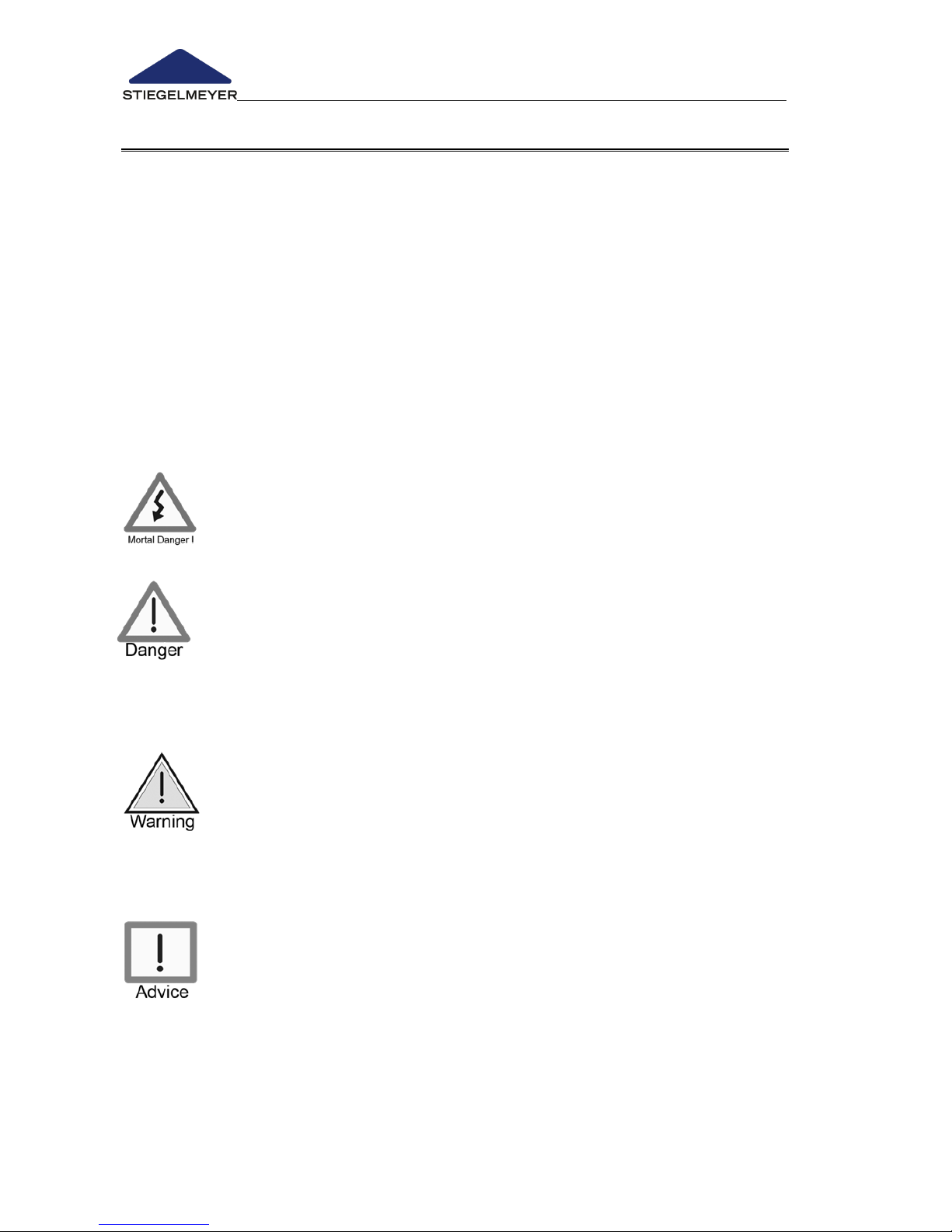
2.2.1 Explanation of the Safety Symbols Used
In this instruction manual, the following safety symbols are used.
Warning of personal injury
This symbol indicates hazards due to electrical voltages. There is
danger to life.
This symbol indicates general hazards. There is danger to life and
health.
Warning of damage to property
This symbol indicates possible damage to property. It is possible that
damage to the drive unit, material or the environment may occur.
Other advice
This symbol indicates a generally useful tip. If you follow it, you will
find it easier to operate the bed. Moreover, this tip is provided for
your better understanding.
Please note:
The safety symbols used are not a substitute for the written safety information.
Therefore read the safety information and follow the instructions precisely!
Page 13

Instruction Manual for Care Bed Libra
Page 11
2.2.2 Safety Information for the Operator
Using this instruction manual, which must be provided with the bed, ensure
that every user is instructed in the safe operation of this bed before using it
for the first time.
Draw every user’s attention to the possible hazards that can arise if the bed
is improperly used. This applies in particular to the use of electrical drives
and safety sides.
In order to ensure permanently safe operation of this medical product with
no risk to occupants, users and third parties, observe your obligations in
accordance with MPBetreibV (Medical Devices Operator Ordinance).
If the bed is in long-term use, test the functions and check for visual
damages (see Chapter 6.2) after a reasonable period of time
(recommendation: annually).
Only permit persons who have been properly instructed to use this bed.
Make sure that substitute staff is also sufficiently well instructed in the safe
operation of the bed.
When other additional equipment (e.g. compressors for positioning systems,
etc.) is attached, ensure that all equipment is safely mounted and
functioning. Pay special attention to:
o Safe hook-up of all loose connector cables, tubing, etc.
o No multiple socket outlets are located under the bed (fire hazard in the
presence of penetrating fluids).
o Chapter 2.3.1of this instruction manual
In the case of ambiguity, consult the manufacturer of the additional
equipment or the Stiegelmeyer company.
Check that your staff is complying with the safety information.
Page 14

Instruction Manual for Care Bed Libra
Page 12 -
2.2.3 Safety Information for the User
Route the cable for the transformer unit in such a way that it
cannot be pulled, driven over or damaged by moving parts
when the bed is operated.
At regular intervals, carry out a visual inspection of the
transformer unit cable to check for mechanical damage
(scuffing, exposed wires, kinks, pressure points, etc.). Such a
check should be performed:
o Whenever the transformer unit cable has been subjected to
any mechanical load, e.g. has been driven over by the bed
itself or by an equipment trolley, has been bent, stretched or
violently pulled due to the bed rolling away while still
plugged into the wall socket.
o Whenever the bed has been moved or relocated before
plugging it back into the transformer unit.
o Regularly by the user when the bed is in constant operation.
If any damage or malfunction is suspected
o unplug the transformer unit immediately from the power
supply.
o indicate clearly that the bed is “Out of Order”
o and take it out of service and
o report it immediately to the operator responsible.
Check the strain relief of the mains cable regularly to ensure that
the screws are tight and secure.
When using external electrical components such as patient lifts,
reading lamps, or compressors for positioning systems, ensure
that all equipment mains cables will not become entangled or
damaged by the moving parts of the bed. This will prevent
potential hazards due to electric shocks, fire, etc.
Multiple sockets that are placed loosely on the ground should
not be used for connecting external electrical components.
Otherwise electrical risks might occur due to damaged mains
cables or penetrating liquid.
Before moving the bed, it is important to always unplug it from the
power supply. Store the transformer unit cable in the cable holder
provided to ensure that it will not fall off or trail on the floor.
(See here Chapter 4.4.1).
Ensure that the operator instructs you in the safe operation of
this bed.
Page 15
Instruction Manual for Care Bed Libra
Page 13
Each time before using the bed, check that it is in perfect
working order to prevent unnecessary hazards for the patient
and delays to work procedures (see Chapter 3.1).
Make sure that the mattress base has travelled to its lowest
position before leaving the occupant unattended. In this way,
you greatly reduce the risk of the occupant injuring
himself/herself as a result of falling when getting in or out of
bed.
Place the handset out of reach (e.g. at the foot end) to protect
the occupant against accidental motor-driven adjustments or
lock the adjustment options of the handset if:
o The occupant is unable to operate the bed safely or free
himself/herself from potentially dangerous positions.
o The occupant could be at risk due to inadvertent adjustment
of the electric motors.
o The safety sides are raised (risk of limbs being crushed or
trapped when adjusting the backrest or thigh rest).
o Children are left unsupervised in the room with the bed.
The adjustments may then only be carried out by, or in the
presence of, an instructed person.
Ensure that no obstacles such as night tables, window sills,
sloping ceilings, floor cable ducts or chairs could impede
adjustments to the bed, to prevent damage to load-bearing
parts of the bed and to the obstacles.
When not in use, always stow the handset in such a way that it
can not fall onto the floor (hang it on the hook). Make sure that
the cable will not be damaged by moving parts of the bed.
Page 16
Instruction Manual for Care Bed Libra
Page 14 -
2.3 PRODUCT DESCRIPTION
2.3.1 Designated Use
- This bed serves as a comfortable solution for positioning the patient and to
facilitate the care of infirm persons in need of care in homes for the aged
or nursing homes and comparable medical facilities. For detailed use
instructions, see Chapter 9.5.
- Use in hospitals is only permitted in rooms designed for medical treatment
of the application group 0 (in accordance with VDE 0100 part 710, (previously
VDE 0107)). This care bed was not designed for any other usage!
- This bed may be intended for care under supervision of a physician and
serve for diagnosis, treatment or observation of the occupant. Therefore it is
equipped with the option to lock the handset.
- This bed has no special connectors for potential equalisation. Please pay
attention to this before connecting additional electrical (medical)
equipment. If necessary, further advice on additional protective measures
can be found:
o In the instruction manuals of these additional electrical devices (e.g.
compressed air positioning systems, infusion pumps, enteral feeding
devices ...)
o In the DIN EN 60601-1-1:2002 standard (Safety of Medical Electrical
Equipment)
o In the VDE 0100 standard part 710 (High Voltage Installations in
Hospitals)(previously VDE 0107).
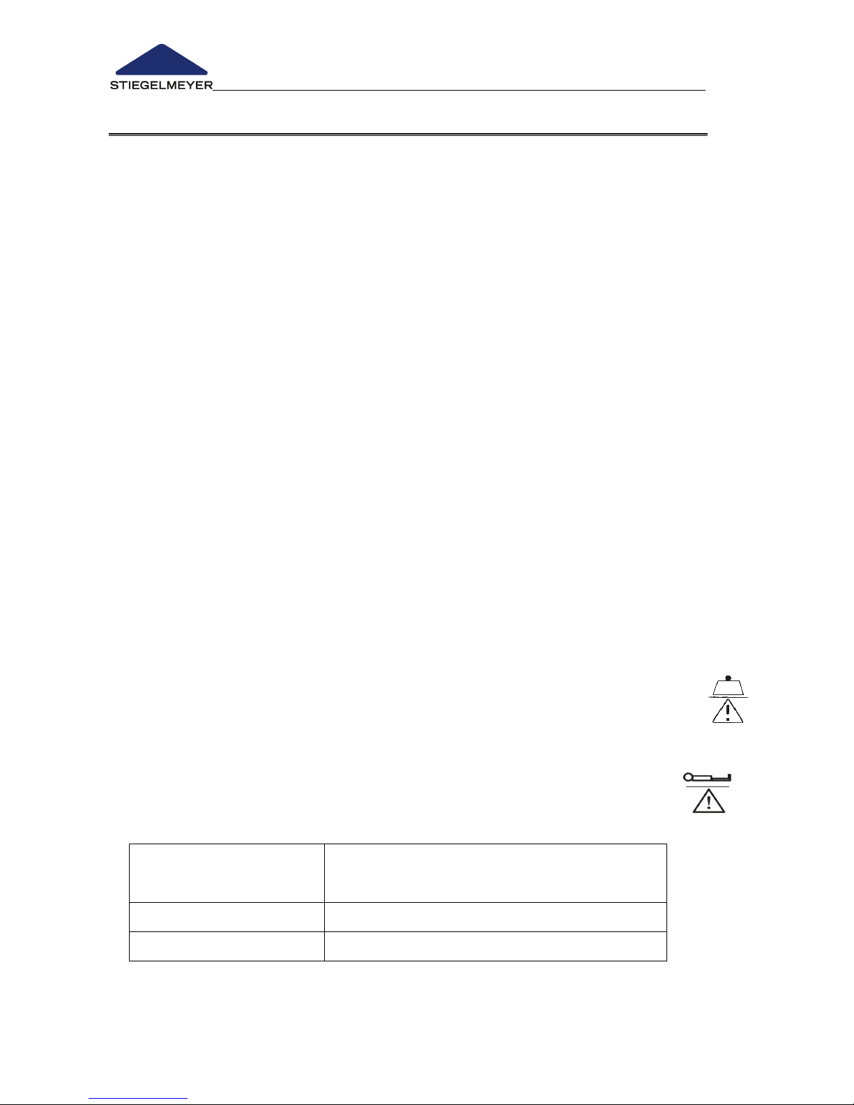
- This bed may be operated without restrictions with a permanent maximum
load of 225 kg (occupant and accessories). Symbol:
- The permissible occupant weight depends on the total weight of
accessories attached to the bed at the same time (e.g. respirators, infusion
equipment,…).
Symbol:
Example:
Weight of Accessories
(incl. mattress)
Safe working load 225 kg:
Maximum permissible occupant weight
10 kg
215 kg
40 kg
185 kg
Page 17
Instruction Manual for Care Bed Libra
Page 15
- Please refer to the safety information provided in Chapter 4.5, especially in
the case of patients in poor clinical condition. Otherwise there is an
increased danger of occupants becoming trapped when the safety sides
are raised.
- This bed may be operated only by persons who have received instruction
in its safe operation.
- This bed is suitable for repeated use. When reusing beds, pay attention to
the necessary requirements:
o Cleaning and Disinfection (see Chapter 5)
o Maintenance / Repeat Inspections (see Chapter 6).
2.3.2 Contraindications
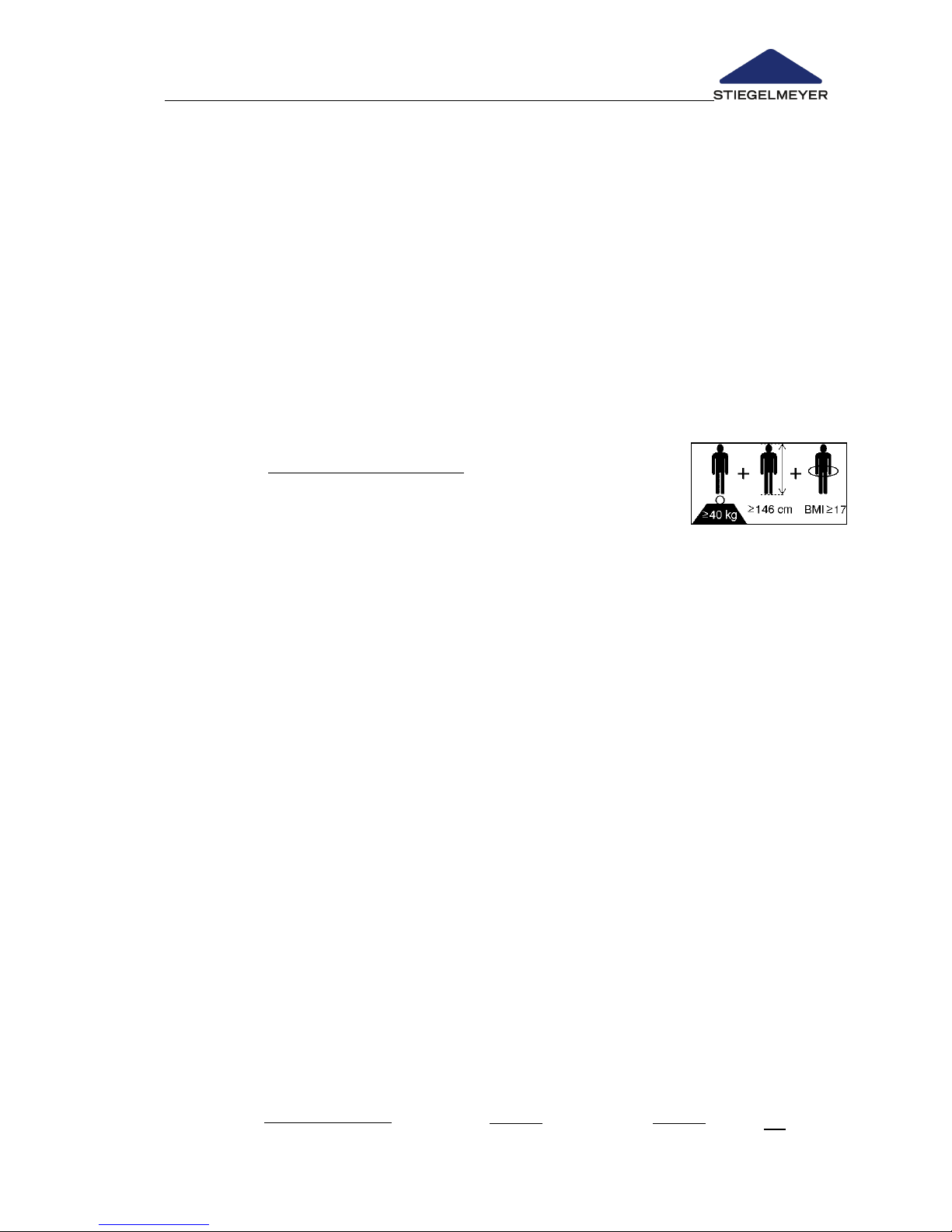
This bed, if used with safety sides, is only suitable for
occupants who do not fall below the following minimum
body size/weight:
o Height: 146 cm,
o Weight: 40 kg
o Body Mass Index
1
“BMI”: 17.
Owing to the smaller limbs of occupants with lower body
measurements/weight, there is an increased risk of entrapment between
the open spaces of the safety sides when safety side systems are used.
The care bed may only be operated according to the conditions described in
this instruction manual.
Any other use shall be regarded as non-compliant with the regulations.
_______________
1
Calculation of BMI =
; example: a)
OK!; b)
Not OK
Sticker on
bed chassis
Page 18

Instruction Manual for Care Bed Libra
Page 16 -
2.3.2 Special bed features
Full-length safety sides on both sides
Mattress base 200 x 90 cm, divided into four sections; external dimensions
approx. 210 x 100 cm (depending on variant)
Electrical height adjustment range for mattress base from approx. 26 to 80
cm
Electrical adjustment of the thigh rest from 0° to approx. 40°
Electrical adjustment of the backrest from 0° to approx. 70°
Electrical adjustment to reverse Trendelenburg position of approx. 16° (not
possible without being connected to power source)
Moves on four castors, locked in axle pairs
Mechanical emergency release of backrest
2.3.3 Optional Electrical Equipment
- Electrical setting of Trendelenburg position: An external operating device
(handset) allows medical staff to place the occupant in an emergency
position if necessary.
- LED reading lamp: Energy-saving, no hazardous heating as with
conventional lamps, resistant to jolts and vibrations; LED bulb has approx.
50,000 hours lifetime
- Discreet LED night light under the bed provides orientation for the
occupant and prevents falls from occurring at night
2.3.4 Mechanical special equipment (optional)
– Combined safety sides (Mobivit): Combines the advantages of the familiar
full-length and split safety sides and provides maximum protection and the
largest amount of flexibility during use.
– Split MobiFlex safety sides on both sides (D): Our 2-stage, telescopic safety
sides can be adjusted across a range of settings to suit individual needs.
– Pivoting safety sides, both sides (A), covers 2/3 of the mattress base.
– Removable hygiene mattress base made of polypropylene is highly
breathable, thanks to its deep venting slits. It can be simply placed on top
of the mattress base and later removed. It is also easy to care for and can
be cleaned with conventional cleaning agents.
– Removable comfort mattress base is made of 50 separate spring elements.
These elements are designed to mould themselves closely to the shape of
the body and help to ventilate the mattress. Their flexibility also ensures that
the pressure is optimally distributed. The comfort mattress base also
significantly contributes to preventing decubitus.
Page 19

Instruction Manual for Care Bed Libra
Page 17
– Comfortable mechanical quick height adjustment for the backrest (CPR).
– Bed extension can be attached, lengthens the bed by approx. 20 cm,
respectively approx. 27 cm. Longer safety side bars and side panels are
necessary for this. If required, please consult our sales department (see
Chapter 6.4)
– Pillow storage integrated at the foot end; can be drawn out from under
the mattress base
– Wall deflection rollers effective in both horizontal and vertical directions
– Wall spacers, head end + sides; prevent the walls and other things in the
room from being damaged when adjusting the height of the bed.
– Infusions sleeve foot end, a sleeve for holding an infusion stand can be
mounted on the crossbar. More about this in Chapter 4.4.6.
2.3.5 Materials Used
For the most part, the bed was manufactured from steel profiles whose
surfaces were finished with a polyester powder coating or a metal coating of
zinc or chromium.
The headboards and safety sides are made of wood or wood products
whose surfaces have been finished. All surfaces are recognised as being safe
for contact with skin.
Page 20

Instruction Manual for Care Bed Libra
Page 18 -
2.3.6 Structural Design
Mattress base
The mattress base is divided into a backrest, a fixed seat section, a thigh rest
and a lower leg rest. The rests are adjustable. The mattress base can be raised
and lowered horizontally or set to the reverse Trendelenburg position with the
foot end lowered (optional Trendelenburg position also available).
Chassis
The chassis is constructed from welded steel tubing with an optimised scissor
lift design and is equipped with four castors which can be locked in by axle at
the foot and head ends.
Safety sides
To protect the occupant from falling out, the bed has full-length safety sides
(2), or, optionally,
a combination safety side (Mobivit) (6),
a swivelling safety side (A),
a split safety side MobiFlex (D).
The safety sides can be raised, one after the other, from the lowered position
to protect the occupant and then lowered again.
Electric Drive System
The electrical drive system for this bed is single fault-safe and flame-retardant
(V0) and consists of:
an 'external' power supply. The transformer unit consists of: Power
converter and low-voltage connecting cable. The power converter
generates a safe, low voltage current which is not dangerous for
occupant or operator. The transformer unit provides protective lowvoltage power to the control for all drives (motors) through a connecting
cable.
the central control device. All drive motors and the handset, which work
on this safe low voltage are plugged into the central control unit.
the electric motors for the backrest and the thigh rest.
two electric motors for the mattress base height adjustment.
a handset with a flexible hook.
Page 21

Instruction Manual for Care Bed Libra
Page 19
3 Putting into service
No electrical measurements are necessary prior to putting this bed into
service for the first time, since the bed has been tested by the
manufacturer for electrical safety and functionality and left our factory in
perfect condition.
Before putting the bed into service for the first time:
Remove all transport securing devices and packaging film.
Clean and disinfect the bed.
Before putting the bed into service each time:
The user must check that:
- The bed has been cleaned and disinfected.
- The castors are braked.
- The power supply is compatible with the bed (100 - 240 volt AC, 50/60
Hertz).
- The transformer unit is connected and the power cable is routed in such
a way that it cannot be damaged through bed adjustments /being
driven over. Hang any cable which is not being used on the cable
holder (see Chapter 4.4.1)
- The transformer unit, drive cables and handset cable cannot be
damaged by moving parts of the bed.
- No obstacles such as bedside lockers, floor cable ducts or chairs will
inhibit adjustments.
- All adjustment facilities work properly and have been checked (see
Chapter 3.1).
The care bed may be put into operation only after carrying out these
checks!
Page 22
Instruction Manual for Care Bed Libra
Page 20 -
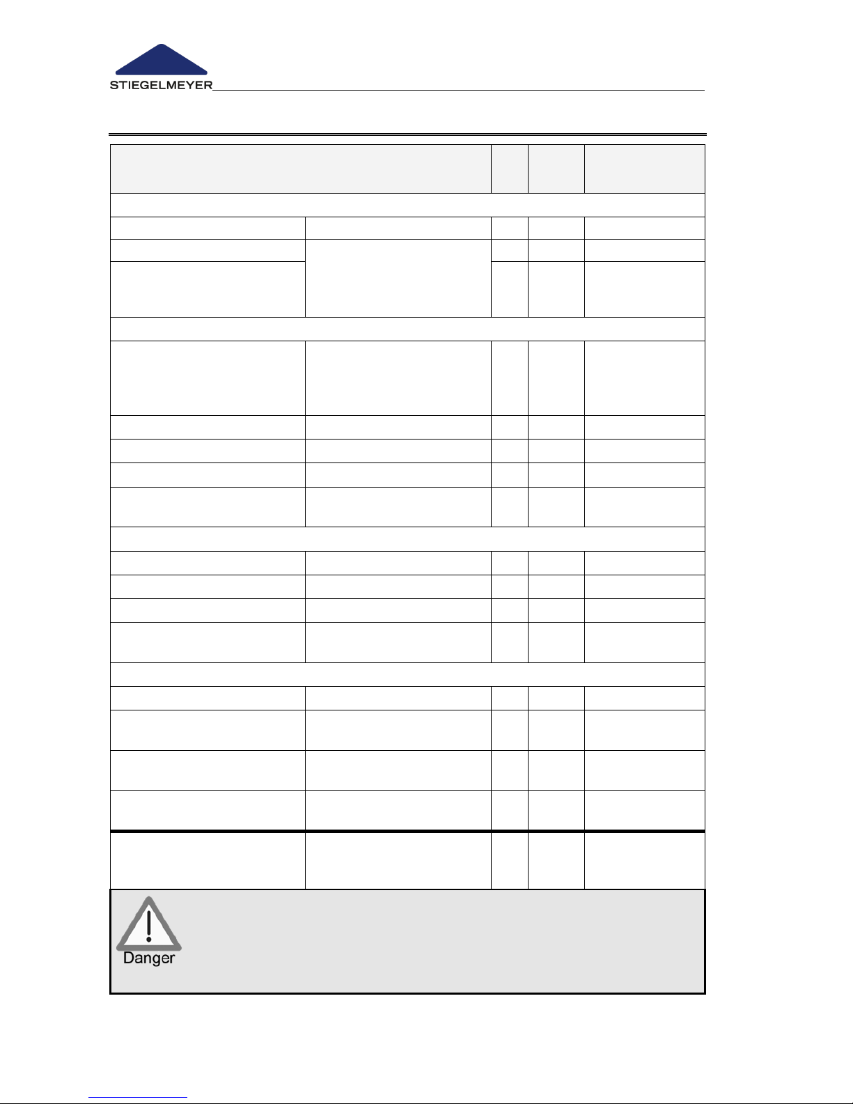
3.1 CHECKLIST: INSPECTION BY THE USER
Inspection
WHAT ? HOW ?
ok
Not
ok
Description
of defect
Visual Inspection of the Electrical Components
Handset
Damage?
Handset cable
Damage, cables routed
away from moving
parts?
Mains cable
Visual Inspection of the Mechanical Components
Patient lifting pole,
location sleeves
Grab handle with strap
(special equipment)
Damage, cracks
Chassis
Damage, deformations?
Mattress base
Damage?
Wooden frame
Damage, splinters?
Safety sides
Damage, deformation,
splinters?
Performance Check of the Electrical Components
Handset, locking functions
Functional test
Rests
Functional test
Height adjustment
Functional test
Reverse Trendelenburg
position
Functional test
Performance Check of the Mechanical Components
Castors
Braking, running
Emergency lowering of
backrest
Test according to
manual
Safety sides
Locking in place,
releasing?
Accessories (e.g. patient
lifting pole, grab handle)
Suitability, fastening,
damage?
Inspector’s signature:
Inspection results:
Date:
If damage or a malfunction is suspected, the bed must be
withdrawn from service immediately and disconnected from the
mains supply until the defective parts have been repaired or
replaced!
Report this immediately to the operator!
Page 23

Instruction Manual for Care Bed Libra
Page 21
3.2 LOCATION REQUIREMENTS
There must be sufficient room available to accommodate the bed's entire
range of adjustments. Furniture, window sills, etc. must not impede
adjustments.
Before using the bed on parquet flooring, check whether the castors could
leave marks on the parquet varnish. The bed can be used on tiles, carpet,
linoleum or laminate flooring without causing any damage.
A properly installed 230 Volt mains socket must be available close to the
bed (preferable).
For transformer unit:
o Hang any cable which is not being used on the cable holder
under the head end.
o Only insert transformer into socket vertically with the cable
end downwards.
o Be careful when moving the bed away: Ensure that the cable
is long enough; unplug transformer unit first.
o Take care when adjusting the height: Maintain a sufficient
distance at the side between the bed and the
transformer unit to avoid damage from occurring. (If necessary, use a
wall spacer)
If any other equipment is attached to the bed, (e.g. compressors for
positioning systems, etc.), ensure that this is securely fastened and that all
additional devices are functioning properly. Pay special attention here to
the safe routing of all loose connector cables, tubing, etc. If you have any
queries or concerns, consult the manufacturer of the additional equipment
or Stiegelmeyer care furniture.
Observe the following points when positioning the bed in order to
minimise, as much as possible, the risk of fire due to external
influences. Instruct users on these points!
Preferably use only flame-retardant mattresses and bedding.
Avoid smoking in bed since the mattress and bedding used may not be
resistant to smoking materials or smoking accessories.
Only use additional equipment which is in perfect working order (e.g.
electric blankets) and other electrical devices (e.g. lamps, radios)!
Ensure that this equipment is used only for the purpose intended and that
instruments are not left unintentionally on or under the bedding (danger of
overheating)!
To prevent risk of fire, do not use any plug connectors from extension
cables or multiple socket bars under the bed.
Page 24
Instruction Manual for Care Bed Libra
Page 22 -
4 Operation
4.1 MOVING AND BRAKING THE BED
The bed is equipped with four lockable castors. The bed is delivered with the
standard paired braking (at head and foot end) (10). If desired, the customer
can order a bed equipped with central braking at the foot end. The bed can
also be moved in the room when occupied.
The bed is not suitable for being moved often and over long
distances outside the room in corridors, across thresholds or on
very uneven floors.
Bring the bed to the lowest mattress base position when moving
the bed greater distances outside of the room.
Each time before moving the bed, ensure that:
o The mains cable cannot be stretched, driven over or
damaged in any other way.
o When moving the bed the mains cable is always stowed in
the designated mains cable holder and does not trail on the
floor (see Chapter 4.4.1)
o Cables, tubes or conductors of mounted additional
equipment that are possibly attached are sufficiently
secured and cannot be damaged.
Otherwise these could be damaged due to the mains cable
being torn off, driven over or crushed. These damages may
lead to electrical risks and malfunctions.
Ensure that the bed is always sufficiently braked when an
occupant is left unattended.
Depending on the location (e.g. by a wall or in a niche), it may be
sufficient to brake only two of the castors. If the bed is standing on
a sloping floor (e.g. on a ramp), then all four castors must be
braked.
A safe and secure bed position must always be guaranteed!
Page 25
Instruction Manual for Care Bed Libra
Page 23
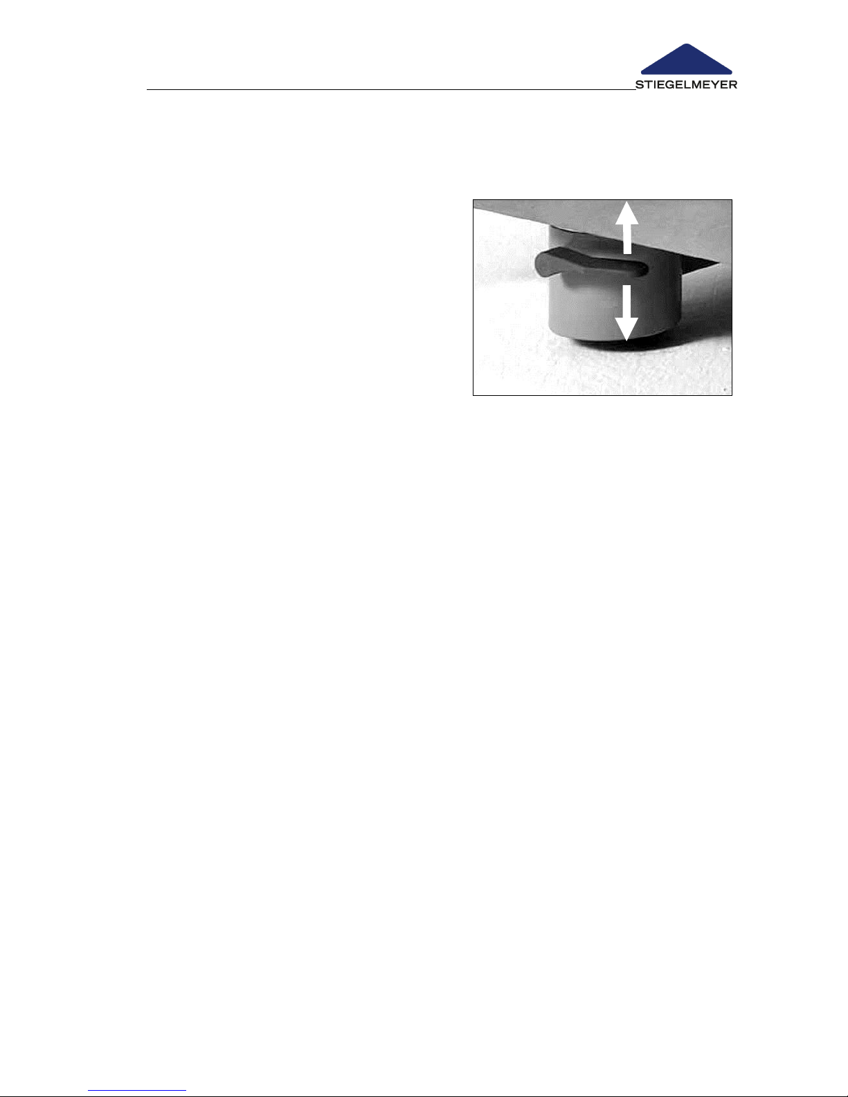
4.1.1 Individual axle braking (Standard)
Operate the castors, one set after the other, on either side at the head or foot
end of the bed. This allows the castor sets at each end of the bed to be
operated with one lever.
Travel: Raise the foot lever (at the foot
and head end) with your foot.
Braking: Press down on the foot lever
(foot and head end) with your foot.
4.1.2 Central braking (optional)
The central braking can only be operated from the foot end. There is a foot
lever for each foot end castors.
Travel: Raise the foot lever with your foot at the foot end.
Braking: Press down on the foot lever with your foot at the foot end.
Page 26
Instruction Manual for Care Bed Libra
Page 24 -
4.2 MECHANICAL ADJUSTMENT OPTIONS
4.2.1 Lower leg rest (LR)
The lower leg rest can be raised and lowered manually when the thigh rest
is raised.
This way an orthopaedic position (stepped bed) or a sloping position of the
lower leg rest can be achieved.
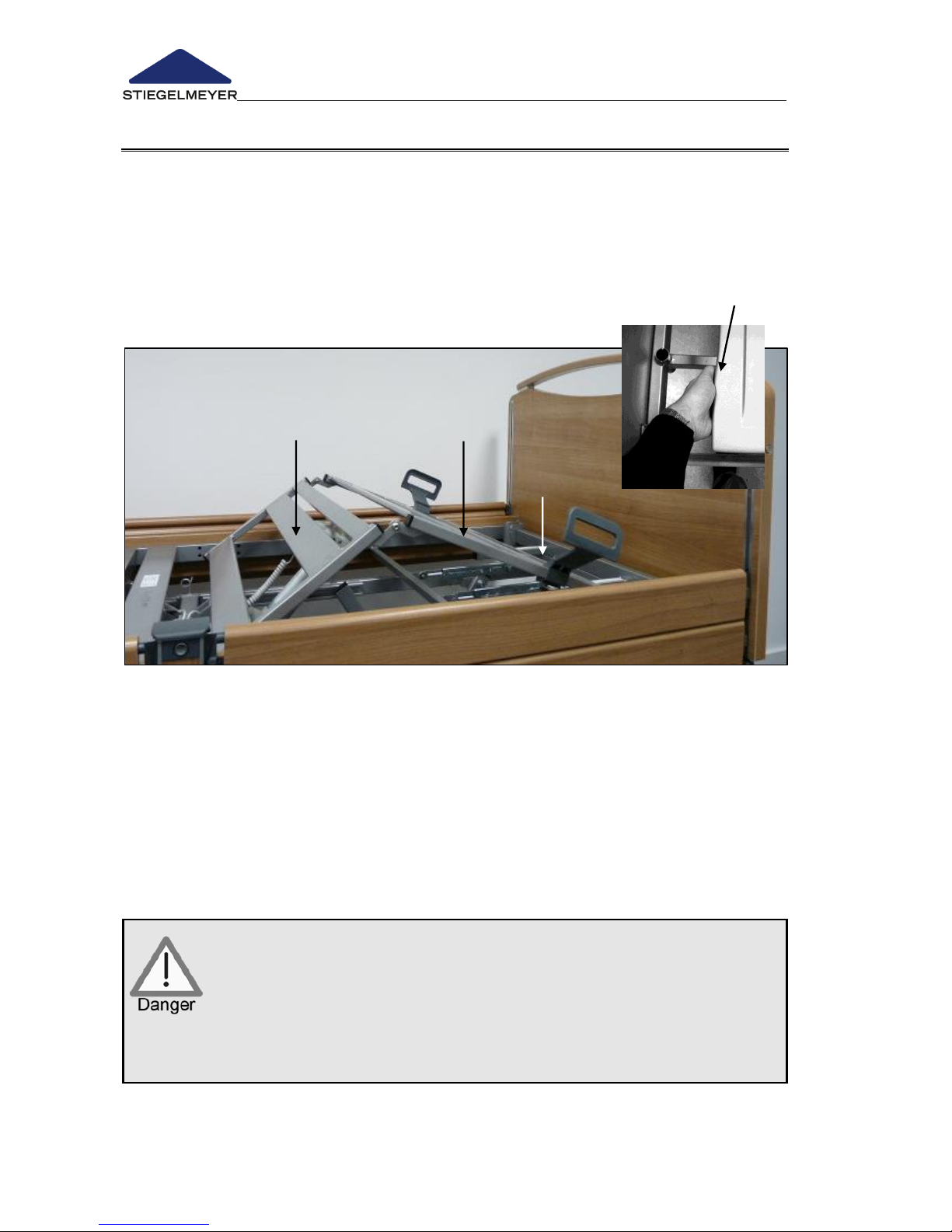
Manually raising lower leg rest (LR)
Raise the thigh rest using the handset.
Lift the lower leg rest on the frame of the lower leg rest to the desired
position and release it slowly.
The lower leg rest engages automatically.
Correct the adjustment using the handset (keys for thigh rest) if desired.
Manually lower lower leg rest
Pay attention to the order of the operating instructions!
Raise the lower leg rest until it reaches the upper limit stop on
the frame.
Lower the lower leg rest slowly.
Risk of crushing! Hold the lower leg rest only at the place
indicated .
There is a risk of injury if the lower leg rest falls uncontrollably.
Page 27
Instruction Manual for Care Bed Libra
Page 25
Lower lower thigh rest using handset
If the upper thigh rest is to be lowered using the handset, the lower thigh rest
will automatically lower with it.
Raise lower thigh rest using handset
If the upper thigh rest is to be raised using the handset, the lower leg rest will
automatically raise with it and audibly engage in several intermediate
positions. When raising the upper thigh rest, the lower thigh rest remains in
position.
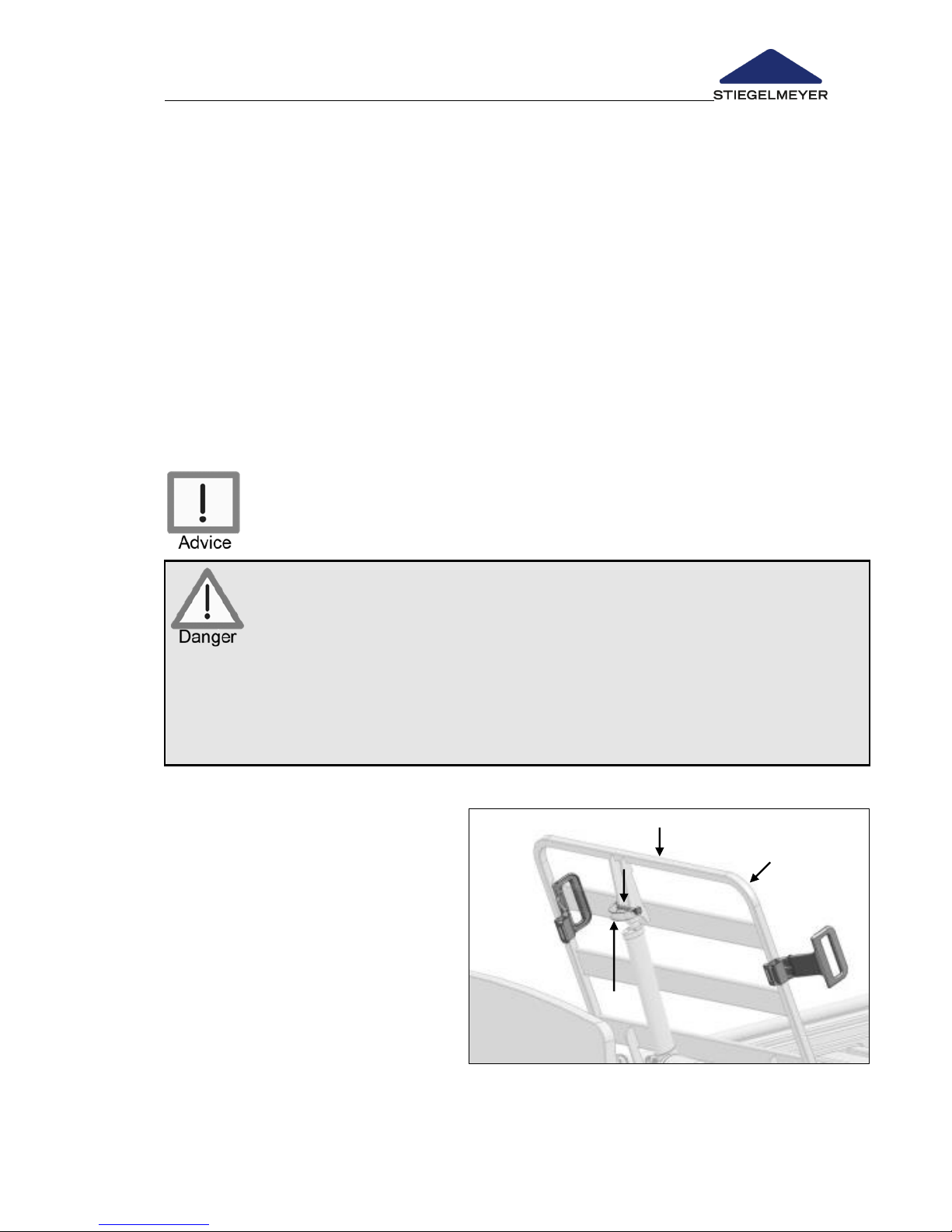
4.2.2 Manual emergency release of backrest
In the event of power supply outages or electrical drive system failures, the
raised backrest can be lowered by hand.
Optionally also by using the 9-Volt batteries (See Chapter 4.3.6).
Please note: Manual emergency release of the backrest requires
two people!
Disregard for this safety information and instructions for use may cause
the backrest to fall uncontrollably, which could lead to serious injuries
for both user and occupant!
Emergency lowering may only be carried out in the case of extreme
emergencies and by users who have a complete command of the
procedure described below.
We strongly advise you to practice emergency lowering of the
backrest under normal conditions. That way, in the case of
emergency you will be able to react quickly and accurately.
Before lowering, the load on the
backrest must be removed.
To do this, the first person raises
the backrest slightly by the
frame and holds it in this
position.
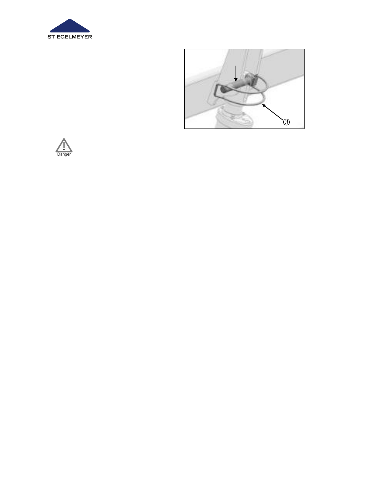
The second person now
removes the bolts . To do this,
open the bent rail and pull
the bolts out along with the rail
from the lifting bar of the
backrest motor.
Page 28
Instruction Manual for Care Bed Libra
Page 26 -
The motor is now separated from the
backrest.
Place the motor on the bed frame by
hand.
After the second person has left the
danger zone, the first person (with the
help of the second person) lowers the
backrest carefully.
Hold the backrest firmly when lowering, otherwise it could fall
uncontrollably!
Now the motor on the lifting bar is no longer connected to the motor
connector mount.
The lifting bar remains in the position it was in when emergency lowering
was carried out.
Restoring the bed to its original state following emergency lowering of the
backrest
Raise backrest by hand.
Swivel the lifting bar up again, secure to the motor connector mount with
the bolts and fold the bent rail back.
Page 29
Instruction Manual for Care Bed Libra
Page 27
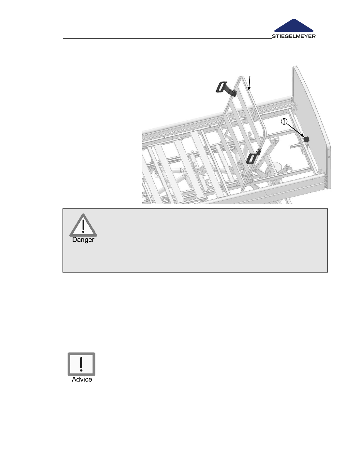
4.2.3 Emergency release of backrest using Quick Release (optional)
If a power outage or
outage in the
electrical drive system
has occurred, it is
possible to manually
lower a raised
backrest by one
person without
removing the motor
through a Quick
Release device.
There is a red
operating lever on the
head end on the bed
frame .
Risk of crushing! When lowering the rests, ensure that the patient’s
limbs are not underneath the backrest. Otherwise, the weight of
the rests could cause limbs to be trapped or crushed.
The backrest can drop very quickly in the case of heavy occupant
once the operating lever has been activated!
Always grip the backrest by its frame with one hand so as to
“control” the adjustment.
Proceed as follows:
1. Grasp the frame of the backrest with one hand.
2. With the other hand, push the red operating lever upwards and guide
the backrest down to the desired position.
Hold the operating lever down until the backrest is completely
lowered.
The backrest can also be held in position by letting go of
the red operating lever.
If there is no load on the backrest, you should also press down
lightly on the backrest with your hand for emergency release.
As soon as the drive system has power again, the backrest can
be adjusted with the handset.
Releasing the backrest using the 9-Volt batteries (see Chapter 4.3.6)
Page 30
Instruction Manual for Care Bed Libra
Page 28 -
4.3 ELECTRICAL ADJUSTMENT OPTIONS
4.3.1 Special Safety Information on the Electrical Drive System
When making any adjustments, ensure that no limbs from the
patient, user or other persons, especially playing children, are
under the rests or the bed frame. Otherwise, this could lead to
trapped or injured limbs.
Lock the operating functions for the occupant on the handset if
- The occupant is unable to operate the bed safely,
- The occupant is unable to free himself/herself from
potentially dangerous situations,
- The occupant is liable to an increased risk of entrapment
during backrest and thigh rest adjustments when the safety
sides are raised
- The occupant could be at risk from inadvertent adjustment
of the electric actuators,
- Children are left unsupervised in the room with the bed.
Upon delivery of the bed, a locking key for the handset is
supplied along with this instruction manual. The locking key is not
intended for use by the occupant. The locking key should remain
with the user for safekeeping.
Adjust the mattress base height whenever necessary, but at
least once a day, to the uppermost or lowest height. This
automatically equalises the two independent adjustment motors
and results in a level horizontal mattress base.
When using accessories on electrically adjustable beds, the
following applies: Make sure that the arrangement of
accessories does not produce any crush or shearing zones for
the patient when the backrest and thigh rest are adjusted. If
that cannot be guaranteed, the user must safely prevent the
backrest and thigh rest from being adjusted with the handset.
Make sure that the mains cable and the cable of the handset
cannot be trapped or otherwise damaged.
Before moving the bed, always make sure that you have
unplugged it from the transformer unit supply. The transformer
unit may not fall to the ground or touch the floor ( 4.4.1). Not
observing these restrictions may cause the transformer unit to
become permanently damaged.
Each time before moving the bed, ensure that the mains cable
will not be stretched, driven over or damaged in any other way.
When moving the bed, the mains cable must be stowed in the
designated mains cable holder ( 4.4.1).
In order to avoid damages, ensure that no obstacles such as
furniture or sloped ceilings could impede adjustments to the bed.
This is to avoid damage.
Page 31
Instruction Manual for Care Bed Libra
Page 29
Patient lifts or other devices may be put under the bed. Ensure
when the mattress base is at the lowest height that the drive
components of the bed are not damaged – if in doubt raise the
mattress base height by about 10 cm before using the patient lift.
Ensure that the 24 volt power supply cable and handset cable
cannot be driven over or otherwise crushed when the bed is
moved.
In the case of malfunctions, an electronic overload switch
deactivates the drives in order to protect the control unit and
motor. Once the malfunction has been remedied, adjustments
are once again possible via the handset.
Electrical adjustments are only possible when the bed is properly
connected to the mains supply
If the load is too high, an electronic overload switch is activated
and the control unit is automatically switched off. When the
overload is removed, the drive unit system can be reactivated by
pressing the appropriate button on the handset.
Continuous operation must not exceed two minutes! After this
time, a rest period of at least 18 minutes must be observed.
(Alternatively: one minute continuous operation followed by a
nine minute rest period, etc.)
For safety reasons, when the maximum operation time is purposely
disregarded, a thermal safety device will permanently cut off the
power supply to prevent the drive unit system from overheating
due to continuous “playing”.
The adjustment range for all functions is electrically / mechanically
limited to the permitted ranges.
As with every electrical device, even if all specified limit values are
observed during operation, interference from and to other closely
situated electrical equipment cannot be completely eliminated
(e.g. “crackling” in a radio). In such cases, increase the distance
from the device. Turn off devices that have disturbance.
Page 32
Instruction Manual for Care Bed Libra
Page 30 -
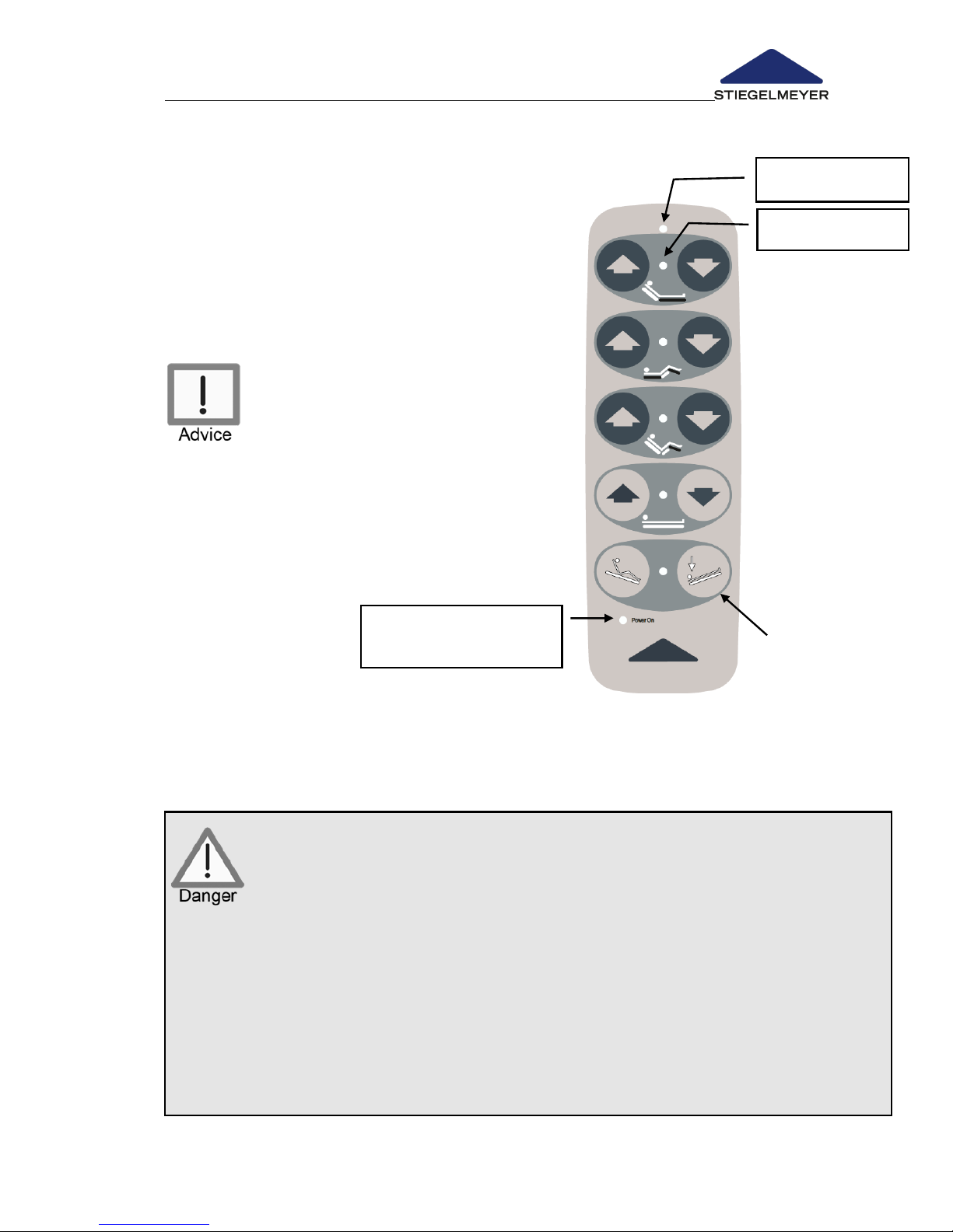
4.3.2 Handset (Standard)
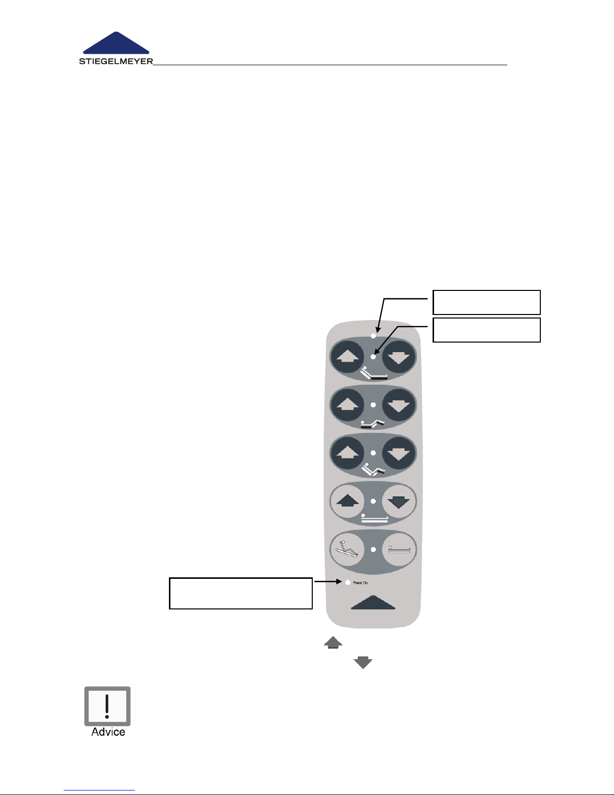
The bed functions can be activated by the occupant or the user with the
handset. For safety reasons the handset is equipped with a locking function.
Depending on the clinical condition of the occupant, the user can lock
handset adjustments when deemed necessary by the supervising doctor
(Chapter 4.3.5).
- The bed is ready to operate when the
LED in the handset is lit up (ready to
operate LED) and which stays lit as
long as the bed is connected to the
mains supply.
- Released key pairs are indicated by a
lit LED between the key pair. These
LEDs extinguish about 2 minutes after
the last key activation. If the LED
between two keys is not lit, this key pair
is locked.
- The electric motors operate as long as
the corresponding buttons are
pressed.
- All adjustments are possible in both
directions.
- The handset can be hung at any
position on the bed with an elastic
hook.
- The coiled cable provides ample
freedom of motion
- The handset can be cleaned.
- The following basic rule applies to the
keys:
Only one key may be activated at a time. For example, if a
second key is pressed immediately after the first one, the second
key has no effect.
Raise
Lower
Backrest
Thigh rest
Auto contour
Mattress base
height
Sleep position
Sitting position
Function LED (green)
Block symbol (yellow)
Ready to operate LED
(green)
Page 33
Instruction Manual for Care Bed Libra
Page 31
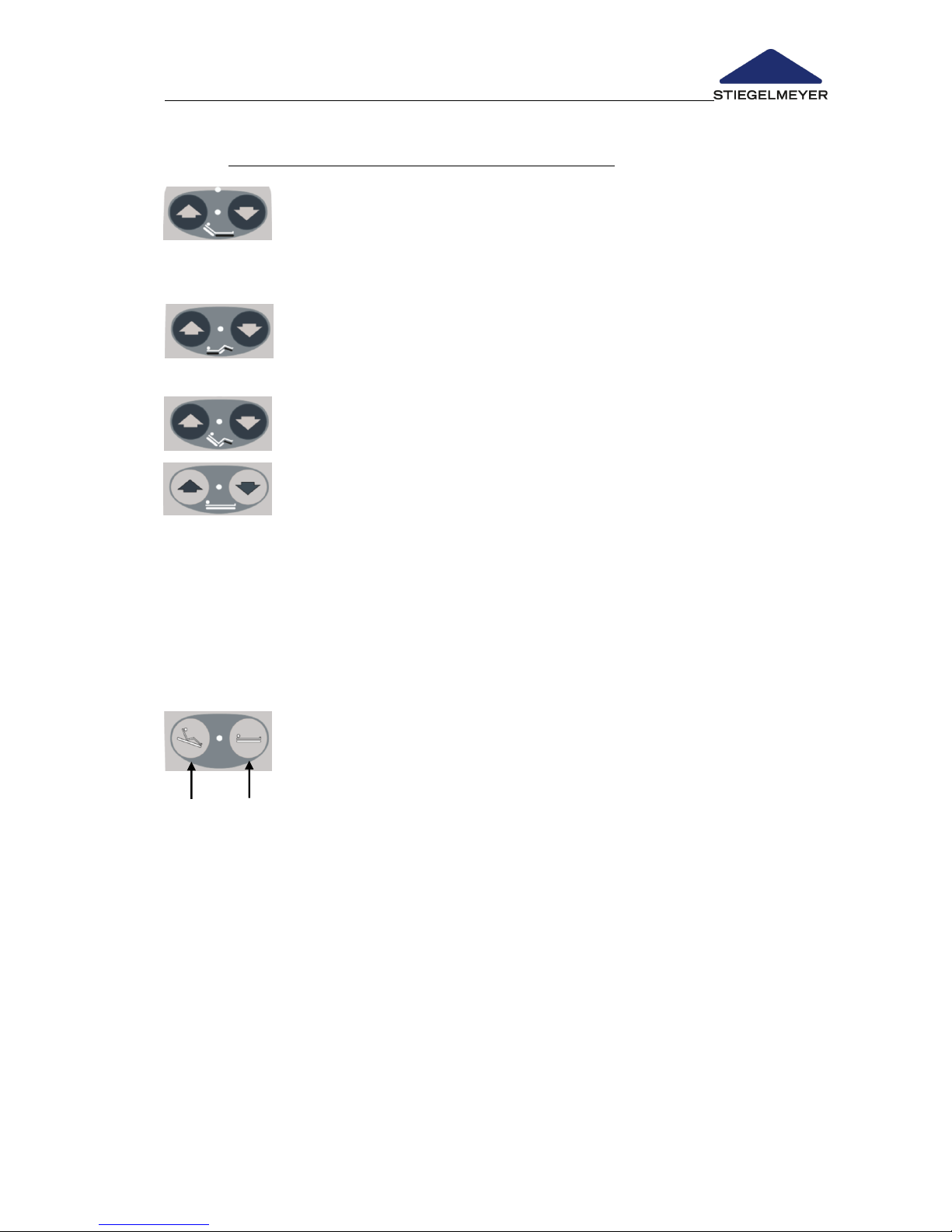
4.3.2.1 Adjustment functions in the standard handset
Adjusting the backrest
The backrest can be raised to approx. 70°.
- Please also refer to Chapter 4.2.2, "Emergency release of
backrest"!
Adjustment of the thigh rest
The thigh rest can be raised to approx. 40 °.
Adjustment of auto contour
The back and thigh rests can be raised at the same time.
Adjustment of the mattress base height
The mattress base height can be adjusted up to approx. 80
cm.
- The mattress base makes an intermediate stop at about 40
cm high when raising or lowering. By repressing the key, it
continues to go up or down.
- If the mattress base is tilted, it moves automatically into a
horizontal position when it reaches the highest or lowest
setting.
Sitting position/Sleep position
Sitting position: The mattress base can be tilted up to approx.
16° when the key is held down.
Sequence of movements for maximum lying comfort ("anti-slip
system"):
"Lift auto contour" for approx. 20 seconds
Stop "Lift auto contour" and start "Reverse Trendelenburg position"
Sleep position: If the button is kept pressed, the mattress
base moves to the lowest position in the following order:
Horizontal (until intermediate stop position)
Back and upper thigh rests are completely lowered (first the
backrest, then the upper thigh rest about 10 seconds later).
By repressing the key, the mattress base continues to move to the
lowest position.
Page 34
Instruction Manual for Care Bed Libra
Page 32 -
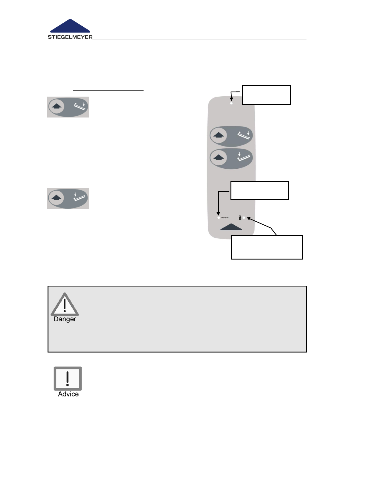
4.3.3 Trendelenburg handset (optional)
The Trendelenburg handset is optional and is used for medicinal purposes
when the bed is being used for long-term care.
4.3.3.1 Adjustment Functions
Press this key when you want to
set the reverse Trendelenburg
position.
If the bed is already in the
reverse Trendelenburg position,
the mattress base is
automatically set horizontally
when it is moved to the lowest
or highest position.
Press this key when you want to
set the Trendelenburg position.
If the bed is already in the
Trendelenburg position, the
mattress base is automatically
set horizontally when it is
moved to the lowest or highest
position.
The Trendelenburg position may only be set under supervision
by a physician or medical professional if the clinical condition
of the occupant requires it.
Wrong use can cause risk for the occupant.
Setting this position is only possible when the bed is connected
to the mains power.
Only one button can be pressed at a time, otherwise all
adjustments stop (emergency off safety function).
Ready to operate
LED (green)
Locked symbol (green)
lit, for released functions
Function LED
(yellow)
Reverse
Trendelenburg
position
Trendelenburg
position
Page 35
Instruction Manual for Care Bed Libra
Page 33
Backrest
Thigh rest
Auto contour
Mattress base
height
Trendelenburg
(Trendelenburg
position)
Sitting position
Function LED
(green)
Block symbol
(yellow)
Ready to operate LED
(green)
4.3.4 Handset including Trendelenburg (optional)
This handset provides the same functions as
the standard handset with the following
difference:
The sleep position button is replaced by the
Trendelenburg key position.
Only one key may be activated at
a time. For example, if a second key
is pressed immediately after the first
one, the second key has no effect.
The Trendelenburg position function should be principally locked. We
explicitly instruct that the Trendelenburg function may only be activated
under supervision by a physician or medical professional. This activation
may only take place when the clinical condition of the occupant requires
it.
Activating or locking the Trendelenburg function may only be
authorised by the medical professionals.
Wrong use can cause risk for the occupant.
To lock functions on the handset, see Chapter "Locking functions
handset".
Keep the locking key safely beyond the reach of the occupant.
Page 36
Instruction Manual for Care Bed Libra
Page 34 -
4.3.5 Locking functions handset
Only users are authorised to use the locking function!
If the clinical state of the occupant is so critical that any
adjustment via the handset places him/her at risk, then the user
must lock this adjustment function immediately. The bed remains in
the position it was in at the time it was switched off.
4.3.5.1 Locking functions of the handset
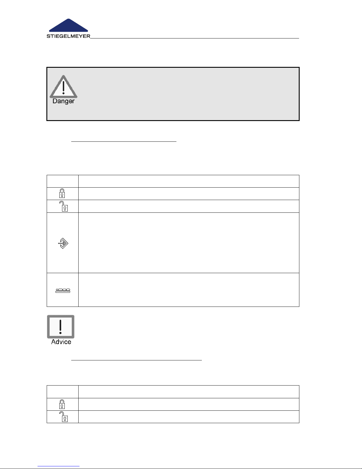
Using the locking key provided, 4 different levels can be selected on the back
side of the handset:
Symbol
Function/meaning
All functions are locked
All functions are active
Programming mode:
Turn the locking key to the programming mode on the back
side of the handset.
Select the key on the front side that is to be locked.
Set the locking key to the occupant mode.
The setting is saved.
Occupant mode:
Only those functions which have not been locked in the
programming mode can be activated.
Do not forcibly turn the locking key beyond the stop of the lock!
The lock or the handset can be damaged.
4.3.5.2 Locking function Trendelenburg handset
The Trendelenburg handset allows 2 different levels to be selected using the
locking key as follows:
Symbol
Function/meaning
All functions are locked
All functions are active
Page 37
Instruction Manual for Care Bed Libra
Page 35
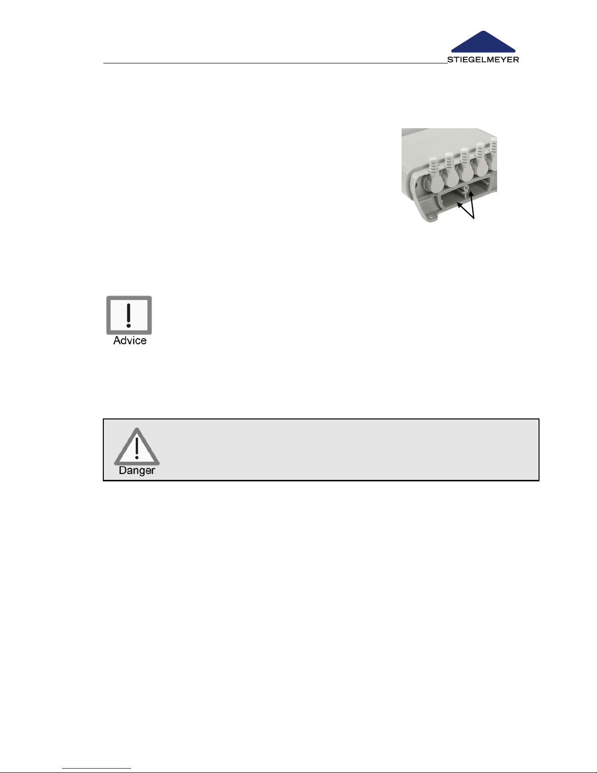
4.3.6 Emergency release using the 9-Volt batteries
The backrest can be released using 2 x 9-Volt batteries if there is a power
outage.
Proceed as follows:
Unscrew the cover of the battery compartment on
the control device.
Insert 2 9-Volt batteries .
Screw the cover back on.
Lower the backrest completely down using the
handset.
The upper thigh rest and height adjustment can also be lowered using the 9Volt batteries.
The batteries are not included in the delivery.
To be able to use this function in an emergency, you should
always have the 9-Volt batteries ready.
Note the limited capacity of the batteries. It is possible that
they will need replacing for additional adjustments such as
lowering the upper thigh rest.
Risk of crushing!
When lowering the rests, ensure that the patient’s limbs are not
underneath the rests. Otherwise, the weight of the rests could
cause limbs to be trapped or crushed.
Page 38
Instruction Manual for Care Bed Libra
Page 36 -
4.4 ATTACHMENTS AND OPTIONAL EQUIPMENT
Optional bed equipment is indicated by an asterisk (*).
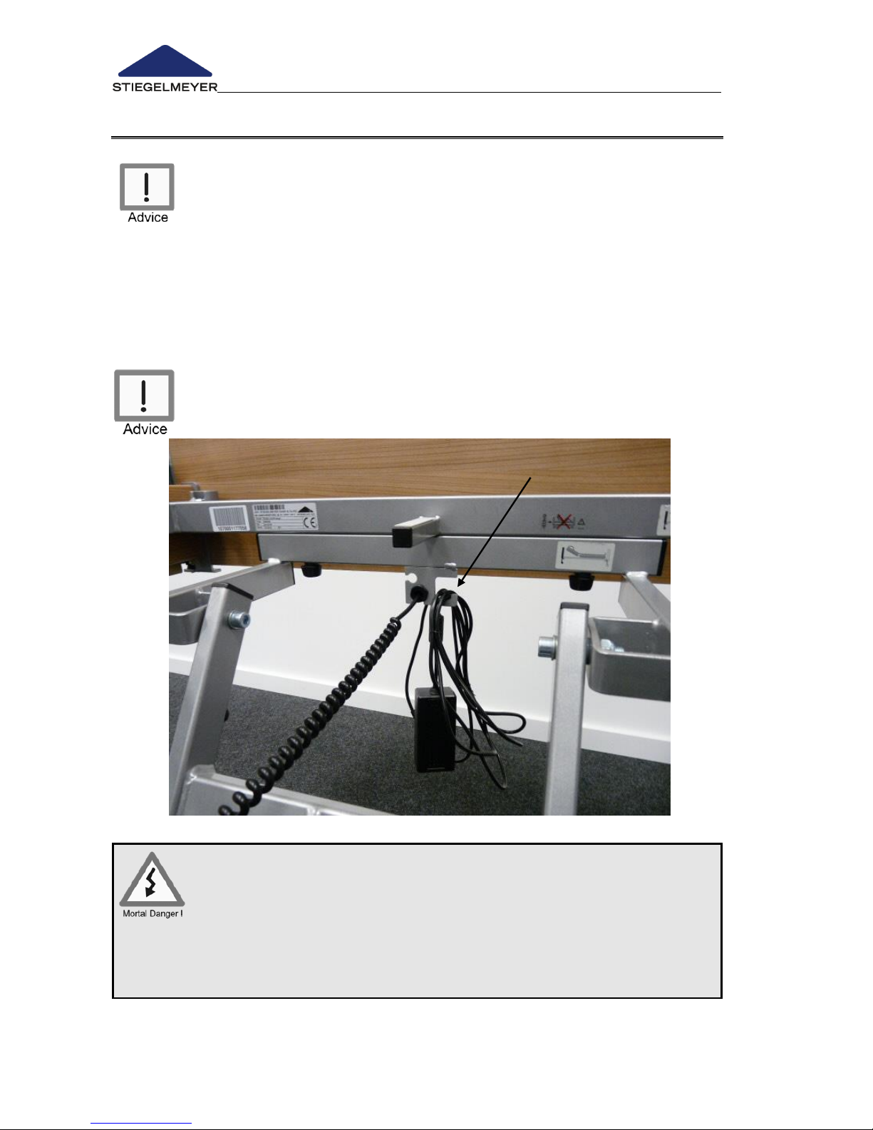
4.4.1 Cable holder
There is a steel cable holder soldered to the bed chassis under the
headboard .
Hang the transformer unit with the cable in the cable holder every time
before moving the bed.
The transformer unit cable must not touch the floor. Otherwise, it
could become damaged by being torn off, crushed or driven over.
Danger of death due to electric shock!
If a damaged cable continues to be used, this can lead to
electric shock, fire and other hazards as well as
malfunctions.
A damaged cable should be replaced without delay.
Page 39
Instruction Manual for Care Bed Libra
Page 37
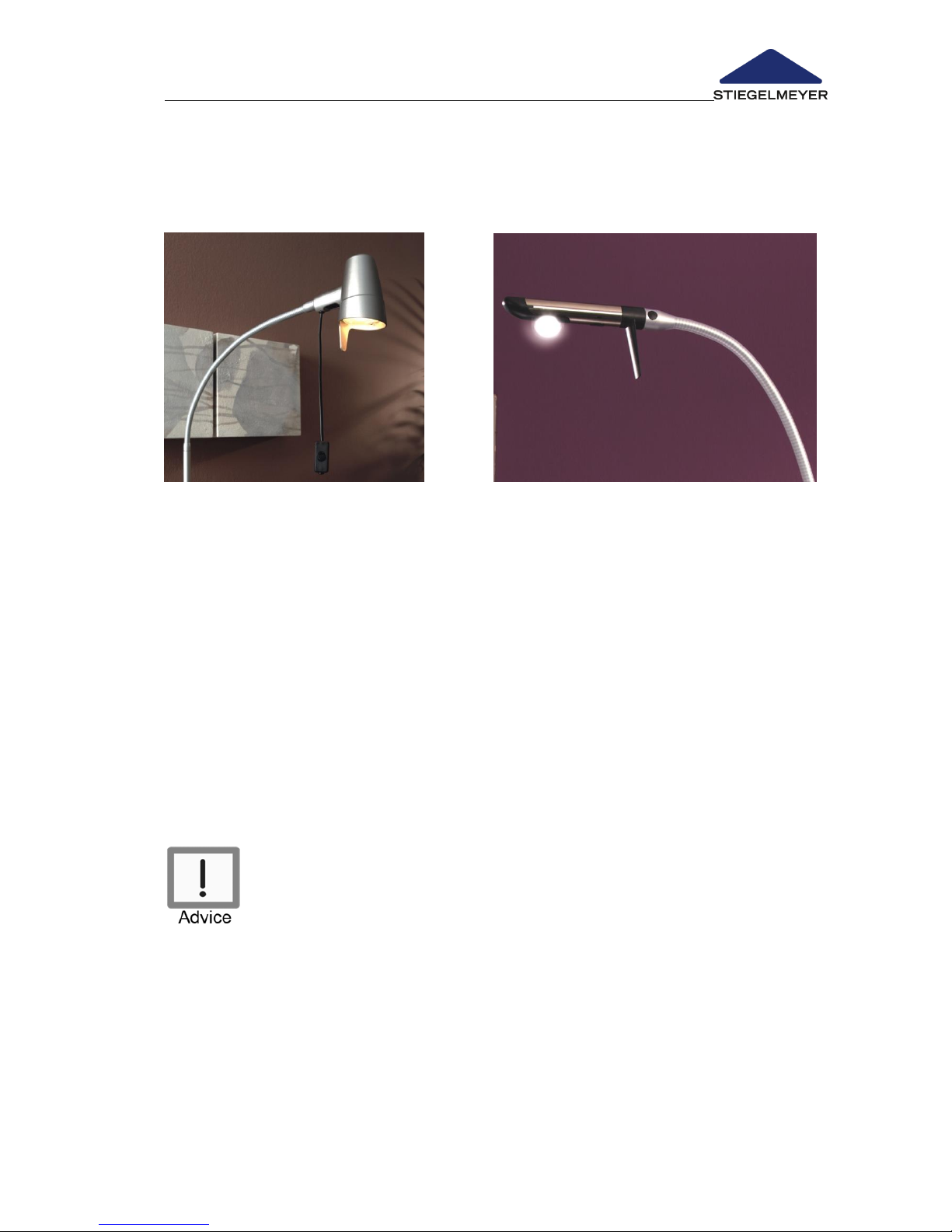
4.4.2 LED reading lamp*
The Libra bed can be optionally equipped with a reading lamp. The reading
lamp is available in two variants as follows:
Variant: Sola
Variant: Stella
The reading lamp is powered by a separate power pack plug and comes
with the following features:
Stand with flexible arm and swivelling lamp head.
For Stella:
Lamp head of high-gloss polished stainless steel with switch and night
orientation light
For Sola:
Cord switch for conveniently switching the lamp on and off
Please read and observe the separate instruction manual
enclosed. Please refer to Chapter for installation instructions. 6.5.2
Page 40
Instruction Manual for Care Bed Libra
Page 38 -
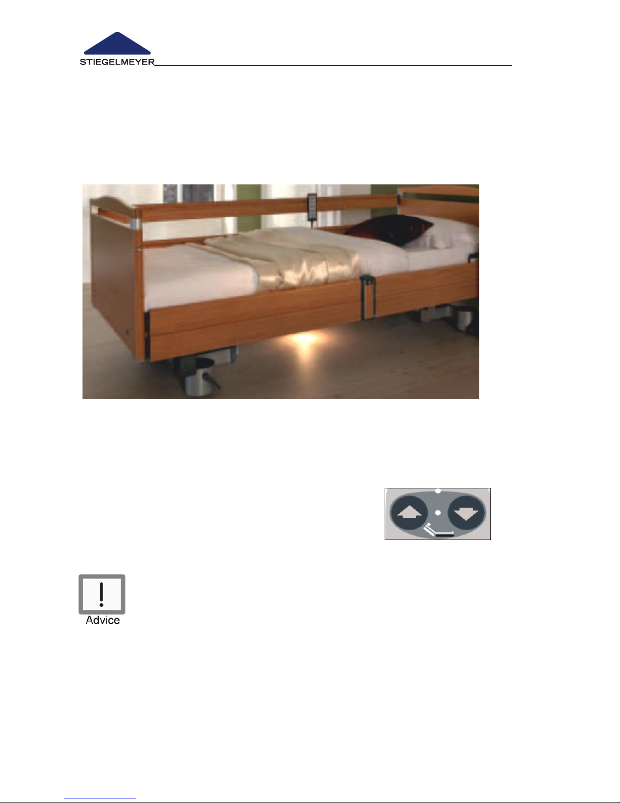
4.4.3 Under bed lighting*
The energy-saving, long-lasting LED under bed light allows safe orientation
during the night and can reduce the risk of falling. The light is sufficiently
restrained, however, that it will not disturb the occupant of the adjacent bed.
Under bed lighting on/off switch
The lighting can be switched on and off on the mains connection using the
standard handset (key for the backrest adjustment):
Proceed as follows:
Press both of the adjacent keys simultaneously
o Lighting switches on
Press again
o Lighting switches off
Please note: If the backrest is locked, the under-bed lighting is
locked at the same time.
Page 41
Instruction Manual for Care Bed Libra
Page 39
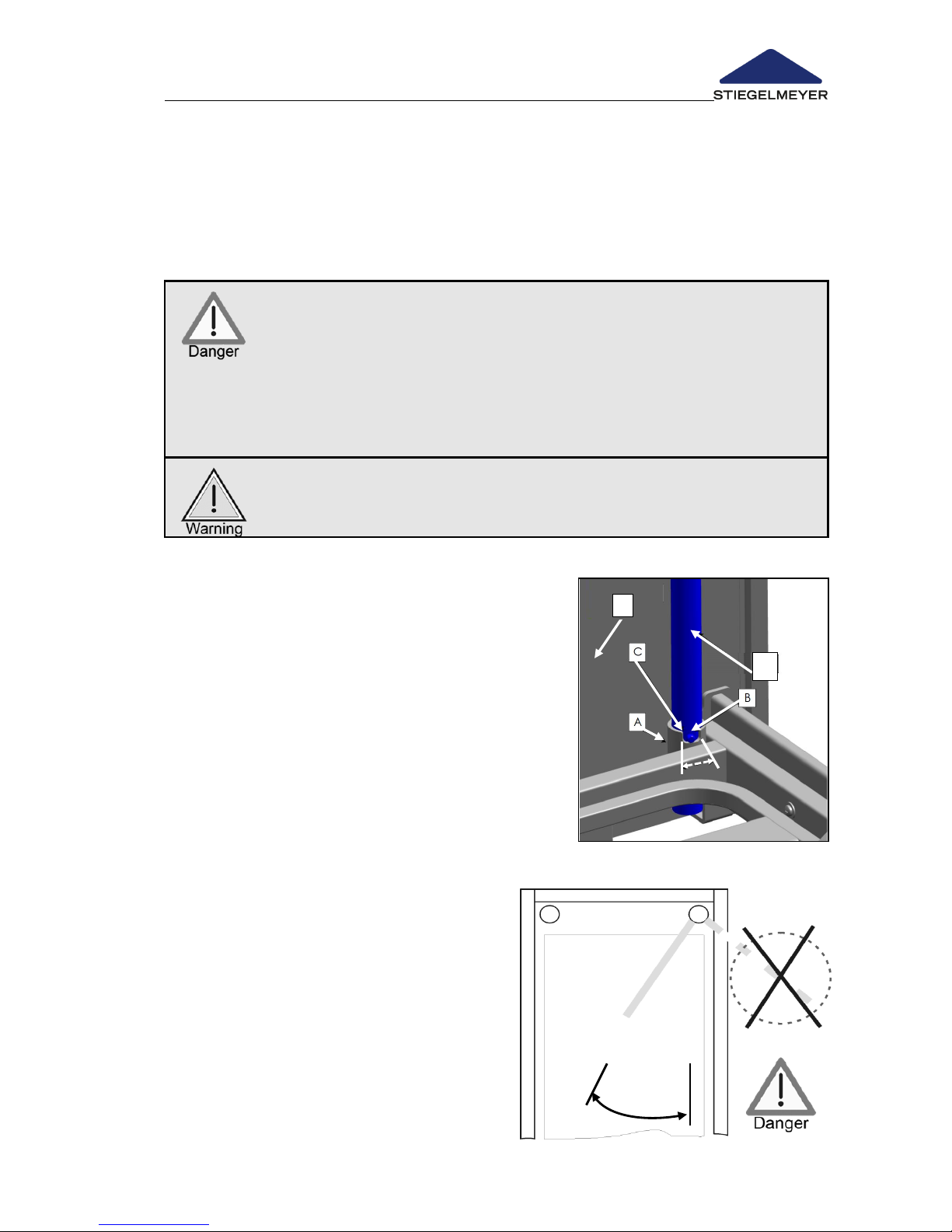
Swivel
range
A
D
4.4.4 Patient lifting pole *
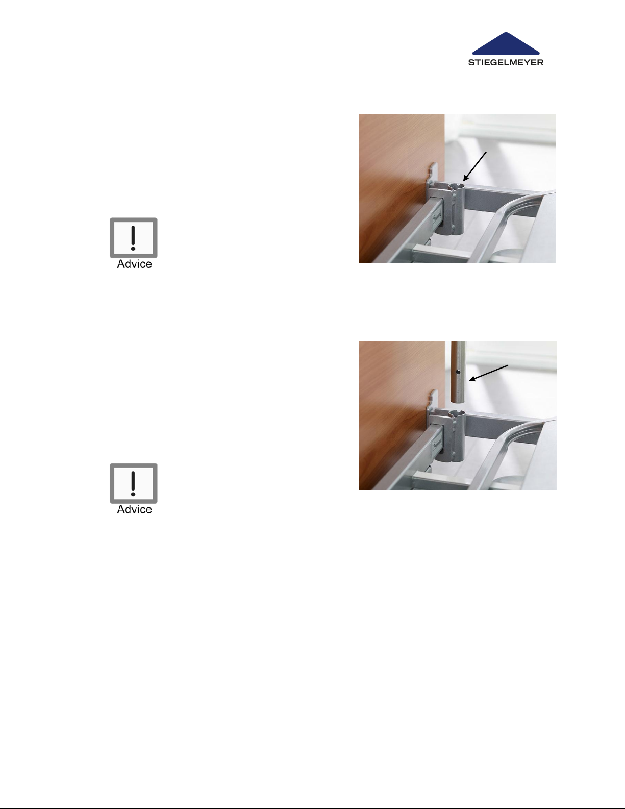
There is a round sleeve (A) with a notch (C) on the upper side at the inner
head end (E) of both corners of the mattress base frame. These are sleeves for
patient lifting poles. The patient lifting pole should be attached to the side of
the bed on which the occupant gets in and out. This will provide assistance
for the occupant when getting in and out of bed.
The maximum loading capacity at the front end of the patient
lifting pole is 75 kg.
The patient lifting pole may not be swivelled beyond the area
of the mattress base and then pressure put on it. Otherwise the
bed may tilt. It is essential that you pay attention to this when
mobilising the occupant or bringing him/her to bed.
The patient lifting pole is not suited for rehabilitation exercises
Pay attention to door clearances when moving beds with
inserted patient lifting poles.
Inserting
Insert the long, straight end of the patient
lifting pole (D) into one of the two sleeves. The
metal pin (B) on the patient lifting pole must
be located in the notch of the sleeve. This
provides a limit for the swivel range of the
lifting pole (see graphic representation below).
The pole is now facing the centre of the bed
and can swing to the side as far as the
restriction allows.
Removing
Pull the patient lifting pole up and out of the
sleeve.
Swivel range of the patient lifting pole
If the pole swings outside the bed area
and is loaded there, there is a danger
that the bed will tip up when weight is
applied to the pole.
Therefore, the metal pin must always sit
in the sleeve recess!
Page 42
Instruction Manual for Care Bed Libra
Page 40 -
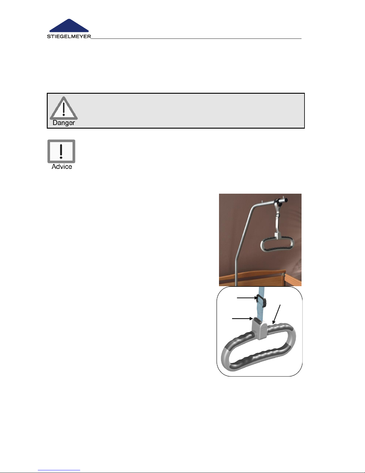
4.4.5 Grab handle* (triangular handle)
The patient lifting pole can be equipped with a grab handle (accessories, see
Chapter 8).
The occupant can use this grab handle to sit up and readjust his/her position.
Check the grab handle and belt regularly for damage (see
Chapters 6.1 and 6.2).
Damaged grab handles or belt must be replaced immediately.
Service life:
We recommend that the triangular grab handle is replaced at
least every 5 years.
Please also refer to the detailed instruction manual supplied with
every grab handle.
Attachment
Attach the grab handle with the hand loop to the
trapeze bars/patient lifting pole.
Ensure that the integrated anti-slip device is
correctly fitted to the fixing points on the trapeze
bar.
Height adjustment
Extend: Pull on the handle holding the button
pressed down whilst guiding the belt slider at
the same time.
Shorten: Hold the handle with the button
pressed whilst moving the belt slider up at the
same time.
Parking position when not in use
The grab handle can be hung over the trapeze bars/patient lifting pole.
Ensure that the grab handle cannot slip off accidentally.
Page 43
Instruction Manual for Care Bed Libra
Page 41
4.4.6 Infusion holder at foot end *
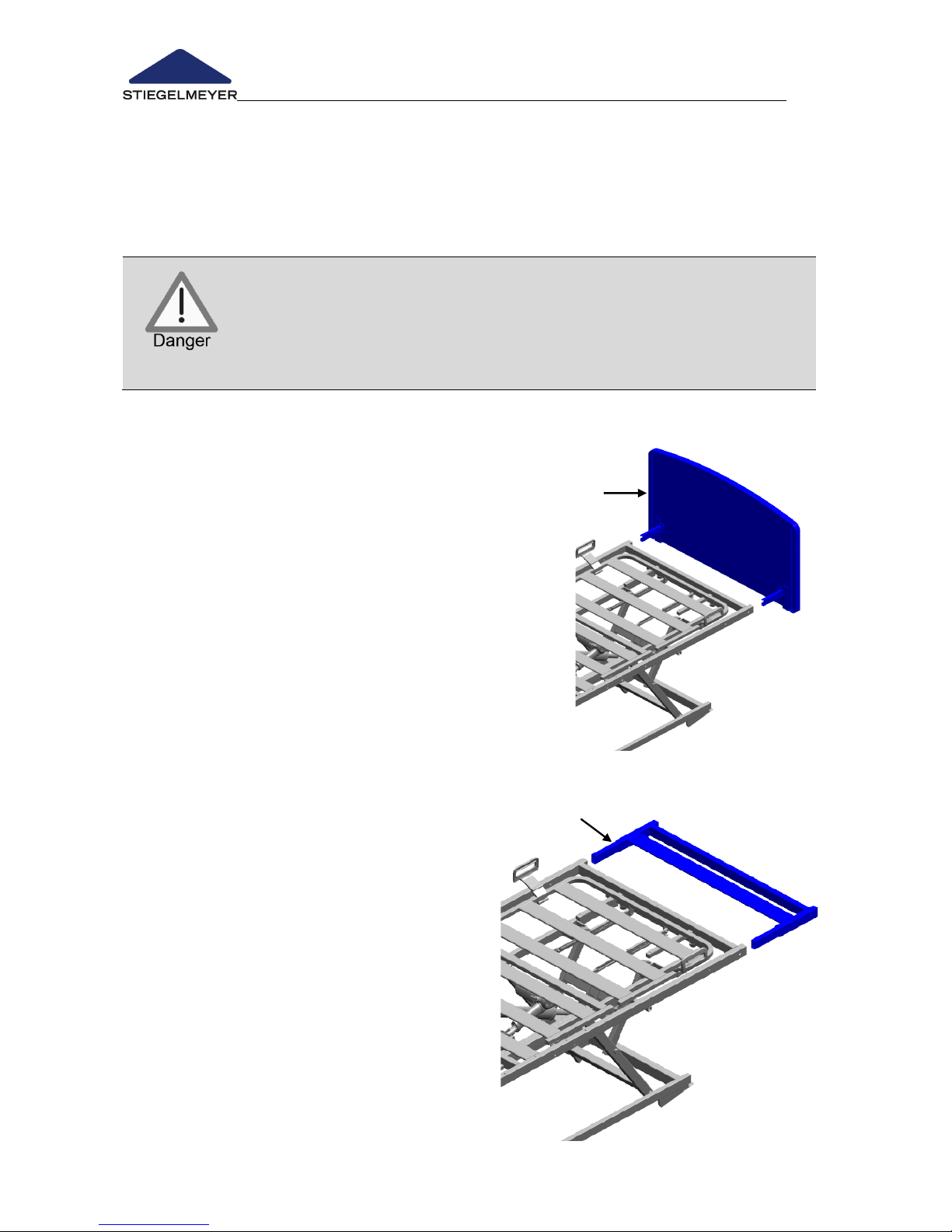
The Libra bed can be equipped with an
infusion holder (sleeve with holder). An
infusions stand can be inserted into the
sleeve.
The infusion holder is attached to the foot
end of the bed.
Attach the infusion holder
following the diagram in a
corner of the mattress frame in
order to avoid risk of crushing.
Proceed as follows:
Fix the holder using the integrated
screw on the foot end of the
crossbar.
Insert the infusion stand into the
sleeve.
It is not possible to attach an
infusion holder with integrated
combined safety sides.
Page 44
Instruction Manual for Care Bed Libra
Page 42 -
4.4.7 Bed extension *
The bed can be equipped with an extension on the foot end of approx. 20
cm or approx. 27 cm. The space that is created is filled with a padding
section. The bars of the safety sides (2)/(6) as well as the side panels (8) must
be exchanged for longer ones.
If the telescopic safey sides are used, only the 27 cm bed
extension may be used.
Failure to take this into account may incur the risk of entrapment of
the patient, since the required distance between the safety side and
the footboard will not be maintained in this case.
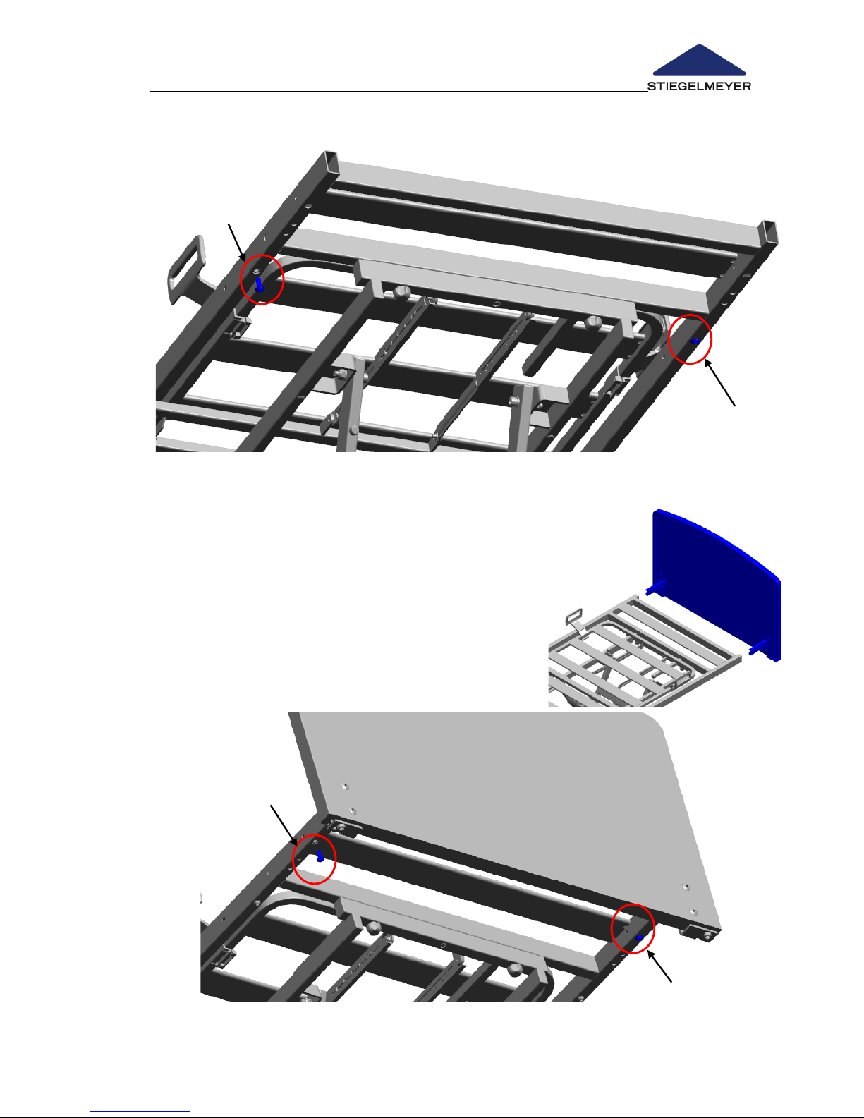
Extending the mattress base
Before extending the mattress base, note the
following points:
The bed must not have an occupant!
The bed must be immobilised.
Proceed as follows:
Remove the safety sides (2)/(6).
Disassemble the side panels (8).
Remove the footboard :
Insert the bed extension .
Page 45
Instruction Manual for Care Bed Libra
Page 43
Screw the bed extension tight .
Place the footboard and screw it tight .
Install the longer side panels (8).
Install the safety sides (2)/(6).
Insert the padding section into the free space.
Page 46
Instruction Manual for Care Bed Libra
Page 44 -
4.4.8 Linen holder *
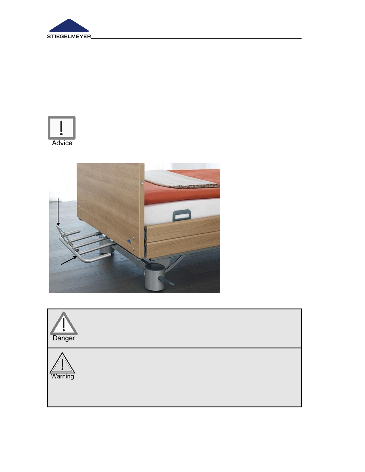
The bed can be optionally equipped with a linen holder that can be pulled
out from under the foot end whenever necessary.
To prevent the bedding from falling, the linen holder has a gallery rail which
can be folded up.
It is not possible to have a bed linen holder with the 27 cm bed
extension.
Risk of injury due to trapped fingers.
When sliding the linen holder back under the mattress base,
watch your fingers!
The maximum load-bearing capacity of the linen holder is 15 kg.
Do not lean on the linen holder!
Do not sit on the linen holder!
Pay attention to the limited clearance under the linen holder
when the mattress base tilts into a full reverse Trendelenburg
position and there is also a bed extension.
Page 47

Instruction Manual for Care Bed Libra
Page 45
4.5 SAFETY SIDES
The bed has safety sides to protect the occupant from falling out of bed. The
standard bed comes with full-length safety sides (2) on both sides of the bed.
The bed can be fitted with the following variants of safety sides as an option.
both bed sides with split safety sides (6)
one bed side with full-length safety side (2) and the other side with split
safety side (6)
both bed sides with split safety sides MobiFlex (D)
both bed sides with swivelling safety sides (A)
The safety sides can be raised from the lowered position next to the mattress
base to protect the occupant.
Depending on the type of mattress base, there are two versions of safety
sides:
Type of safety side
Type of
mattress base
Height of
safety side
Max. mattress
height:
2 bars, full-length (2)
Metal / plastic
41 cm
19 cm
Comfort
37 cm
15 cm
2 bars, in sections (6)
Metal / plastic
41 cm
19 cm
Comfort
37 cm
15 cm
Swivelling safety sides (A)
Metal / plastic
40 cm
18 cm
Comfort
36 cm
14 cm
Split MobiFlex safety sides (D)
Metal / plastic
41 cm
19 cm
Comfort
37 cm
15 cm
Page 48
Instruction Manual for Care Bed Libra
Page 46 -
4.5.1 Full-length safety sides (standard)
Raising
At the head and foot ends, pull the upper beam of the safety side upwards
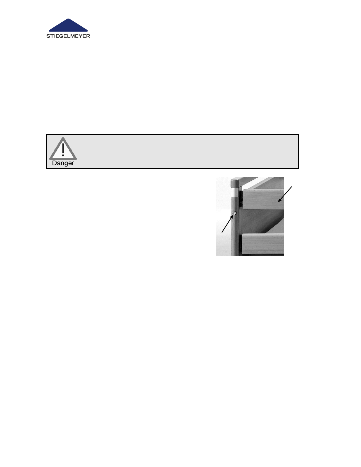
as far as it will go, first at one end and then at the other. The lower bar
follows.
Ensure that the safety side have been securely clicked in by pressing on the
upper bar.
Repeat the procedure on the other safety side.
Lowering
Before lowering the safety sides, ensure that the occupant’s
limbs are not near the plane of movement of the bars. This
prevents crushing and injuries.
1. Lift the upper bar slightly with one
hand and hold it in place.
2. Press the release button and lower
the safety side carefully. Do not let
it drop!
Repeat this procedure for the other
sides.
Page 49

Instruction Manual for Care Bed Libra
Page 47
4.5.2 Special Safety Information for Safety Sides
Safety sides protect the occupant from unintentionally falling out of the care
bed. They are not intended as a device to prevent the occupant from
intentionally leaving the bed.
If not used properly, there is a considerable danger of, for example,
strangulation for the occupant! Please, therefore, bear in mind the following
instructions.
Only use technically perfect, undamaged side guards which lock
securely into place!!
Before using the safety sides, assess and take into consideration
the clinical condition and particular physical build of the resident:
o For example, if the resident is extremely confused or very restless,
avoid using safety sides as far as possible and make use of
alternative safety measures such as posey belts, restraint sheets,
etc.
o For especially small, frail residents, additional protective
measures for reducing the space between the bars on the
safety sides may be necessary. In these cases, use safety side
foam covers (accessory), posey belts, etc. This is the only way to
effectively guarantee patient safety and reduce the risk of the
patient becoming trapped or slipping through the bars.
Only use suitable mattresses (not too soft) complying with DIN
13014 with a volume weight of at least 40 kg/m³ and dimensions
complying with the specifications in the instruction manual for
the bed (in the Chapter "Accessories"), to prevent endangering
patients through trapping or suffocation.
If thicker special mattresses are used (for prevention or therapy),
such as mattresses to prevent pressure sores, an effective safety
side height of at least 22 cm above the non-occupied mattress
must be guaranteed.
If this requirement is not met, the operator is responsible for
taking any additional measures, or other measures he considers
suitable, based on his own risk assessment in view of the clinical
condition of the patient, and in view of the characteristics of the
special mattress, such as additional safety systems for the
patient, regular and more frequent monitoring of the patient or
internal instructions for users.
Page 50

Instruction Manual for Care Bed Libra
Page 48 -
The patient’s risk of falling can be lower:
o The smaller and more settled the patient is
o The softer the mattress is (the patient sinks deeper into the
mattress)
Lock the operating functions for the patient on the handset if the
patient is liable to an increased risk of entrapment during backrest
and thigh rest adjustment when the safety sides are raised,
Otherwise there is a danger of limbs being crushed or trapped
between the safety sides if the patient inadvertently activates the
handset. The effectiveness of the safety sides can also be reduced if
the mattress base is raised to a high level.
Page 51
Instruction Manual for Care Bed Libra
Page 49
4.5.3 Operation of split safety sides *
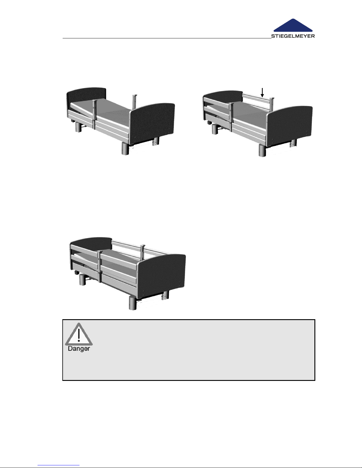
Position as delivered Raising the safety side
Raising the safety sides at the head end
Grasp the middle of the top safety side bar and pull the safety side bar
upwards as far as it will go. Both ends must audibly click into place.
Repeat the procedure on all other safety side bars.
Raising all safety sides
The occupant is not sufficiently protected from falling out of bed if
only the safety sides at the foot end of the bed are raised.
Therefore only ever raise the foot-end safety sides if the head-end
safety sides are also raised.
Maximum protection for the occupant can only be achieved this
way, as with full-length safety sides.
Page 52
Instruction Manual for Care Bed Libra
Page 50 -
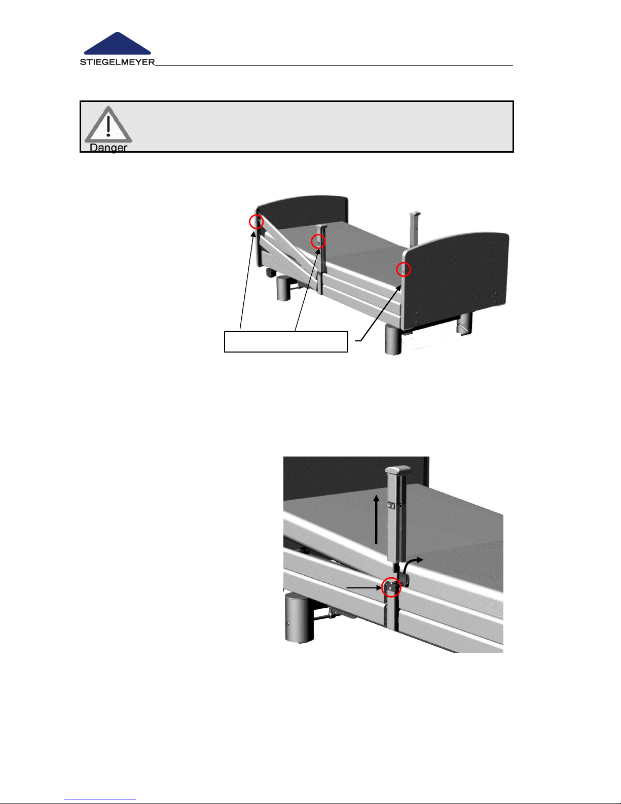
Release button
Lowering the safety side
Before lowering the safety sides, ensure that the occupant’s limbs
are not near the plane of movement of the bars. This prevents
crushing and injuries.
- The following description applies to each of the four separate sections of
the safety sides.
With one hand, raise the
top bar slightly at one
end, and hold it firmly.
With the other hand,
press the corresponding
release buttons and
lower the safety side.
Caution! Do not let it
drop!
Repeat the procedure for the other end of the bar.
Removing and storing the middle post
If the safety sides will not be required for some time, the middle posts can be
quickly removed and conveniently stored:
With one hand, press the
release button and pull the
middle post vertically upwards
with the other hand.
The cover of the socket for
the middle post will then spring
back into place.
Page 53
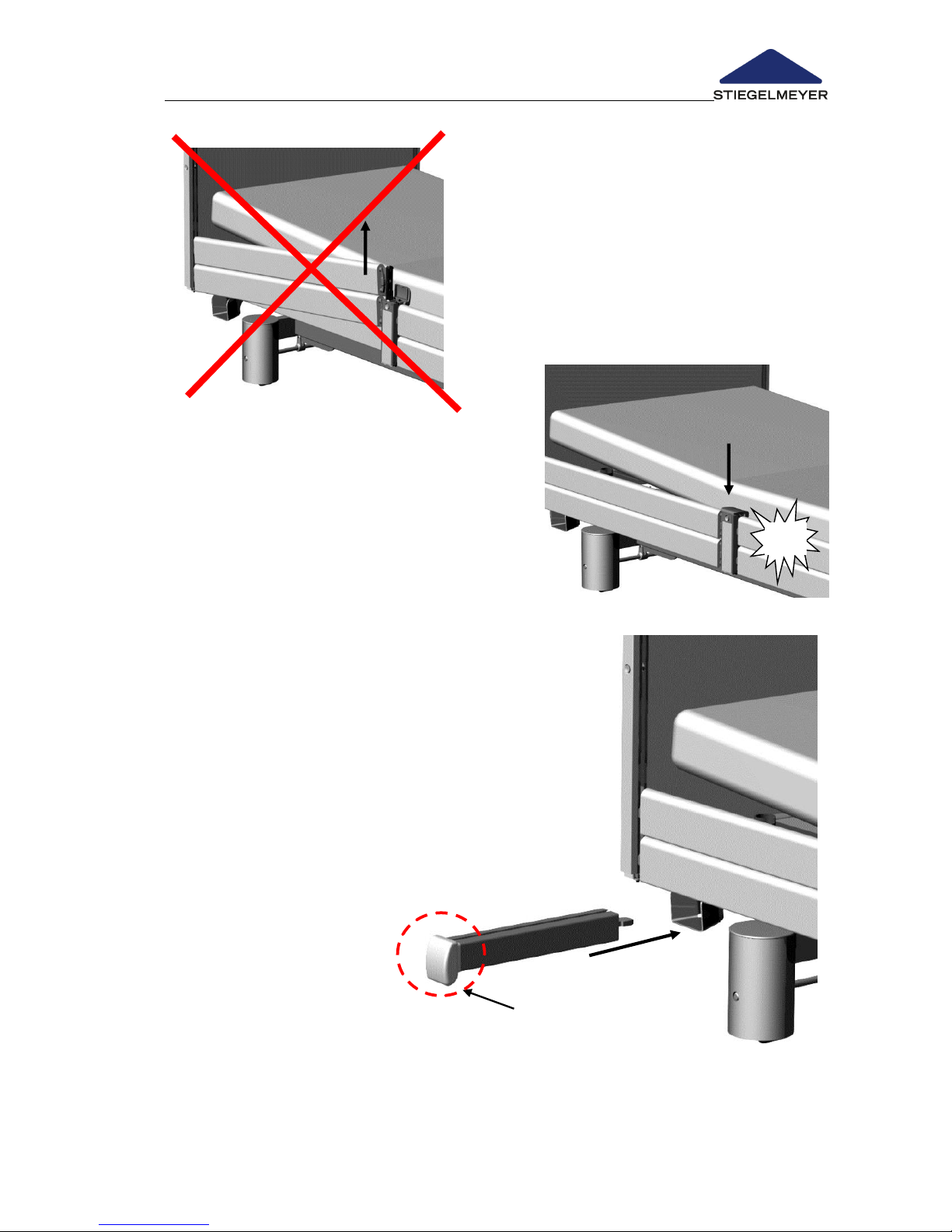
Instruction Manual for Care Bed Libra
Page 51
Avoid lifting the safety side if the middle
post has been removed and the cover
flap is not locked in place, as the safety
side could otherwise be pulled free of its
restraints.
Press the cover down with one hand
until you hear it click into place. The
opening is then properly sealed.
Store the middle post at
the foot end of the bed
by sliding it into the
special holder
underneath the mattress
base, as illustrated here
.
Slide the middle post
gently in as far as it will
go. (The middle post is
automatically secured)
Do not use excessive
force. The post only
fits properly in the
direction shown here.
click
Page 54
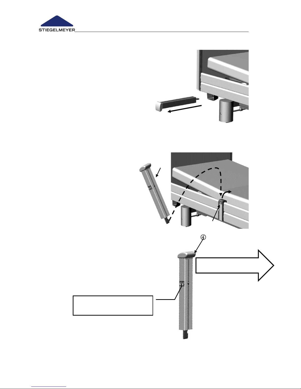
Instruction Manual for Care Bed Libra
Page 52 -
The release buttons must
face away from the bed
Protruding edge to foot end
Fixing the middle post in place
Pull the middle post towards you and
slide it horizontally out of the holder at
the foot end.
Unfasten the cover flap by
pressing the button .
Open the cover by hand and
hold it open.
Slot the middle post into the
post socket as illustrated.
Caution! Take care not to switch the left and right
middle posts!
The release buttons must face away
from the bed
Make sure that the protruding edge
of the knob points towards the
foot end
Page 55
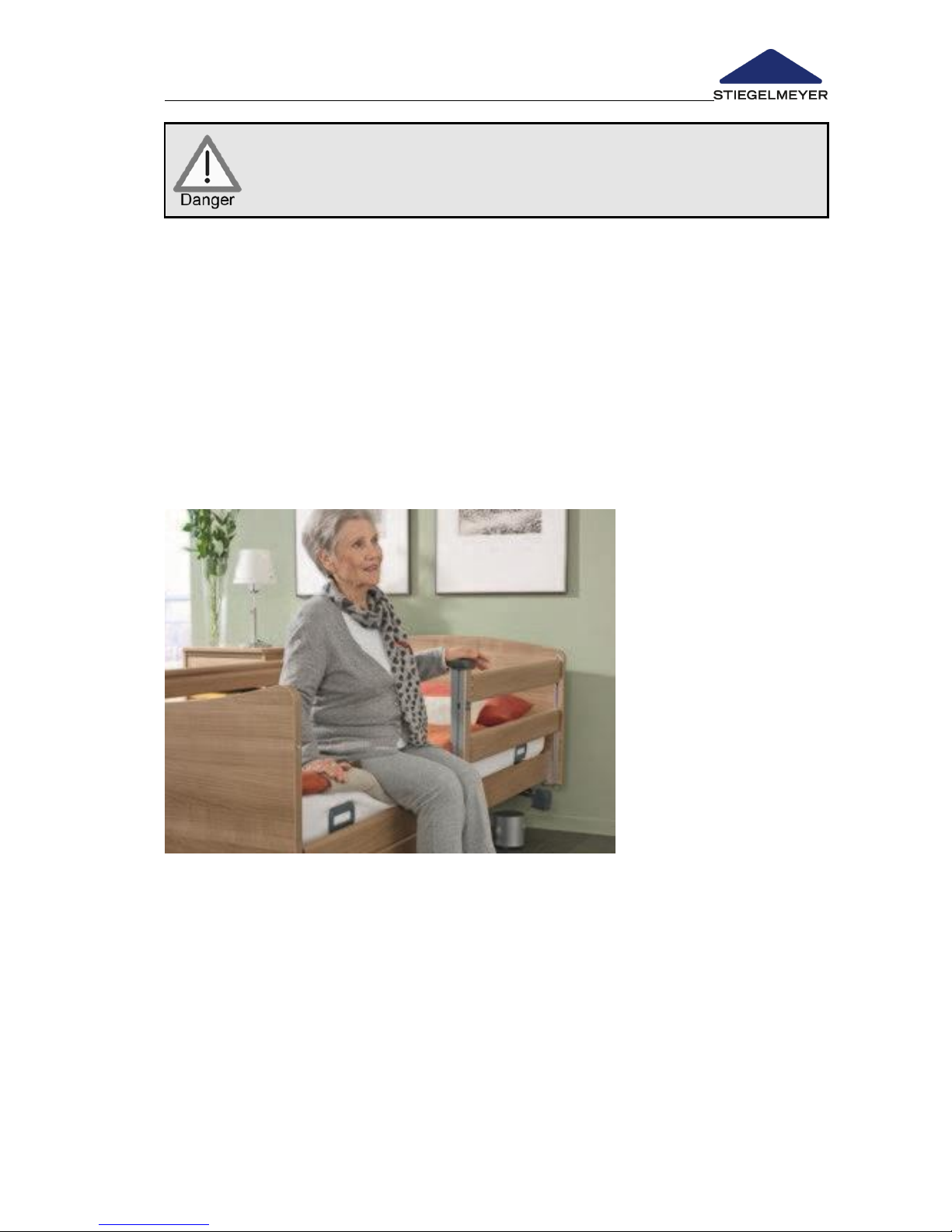
Instruction Manual for Care Bed Libra
Page 53
Make sure that fingers, bed linen, tubes or other objects cannot
become trapped between the middle post and the post socket!
Push the middle post straight down as far as it will go. You will hear it click
into place.
Then check to ensure that it is locked in place by trying to pull it upwards.
It should not be possible to disengage the post.
Other uses for the middle post
If the safety sides (at the foot end) are unnecessary, the middle post can be
used as a mobility aid. The sturdy middle post helps the occupant get into
and out of the bed.
Page 56
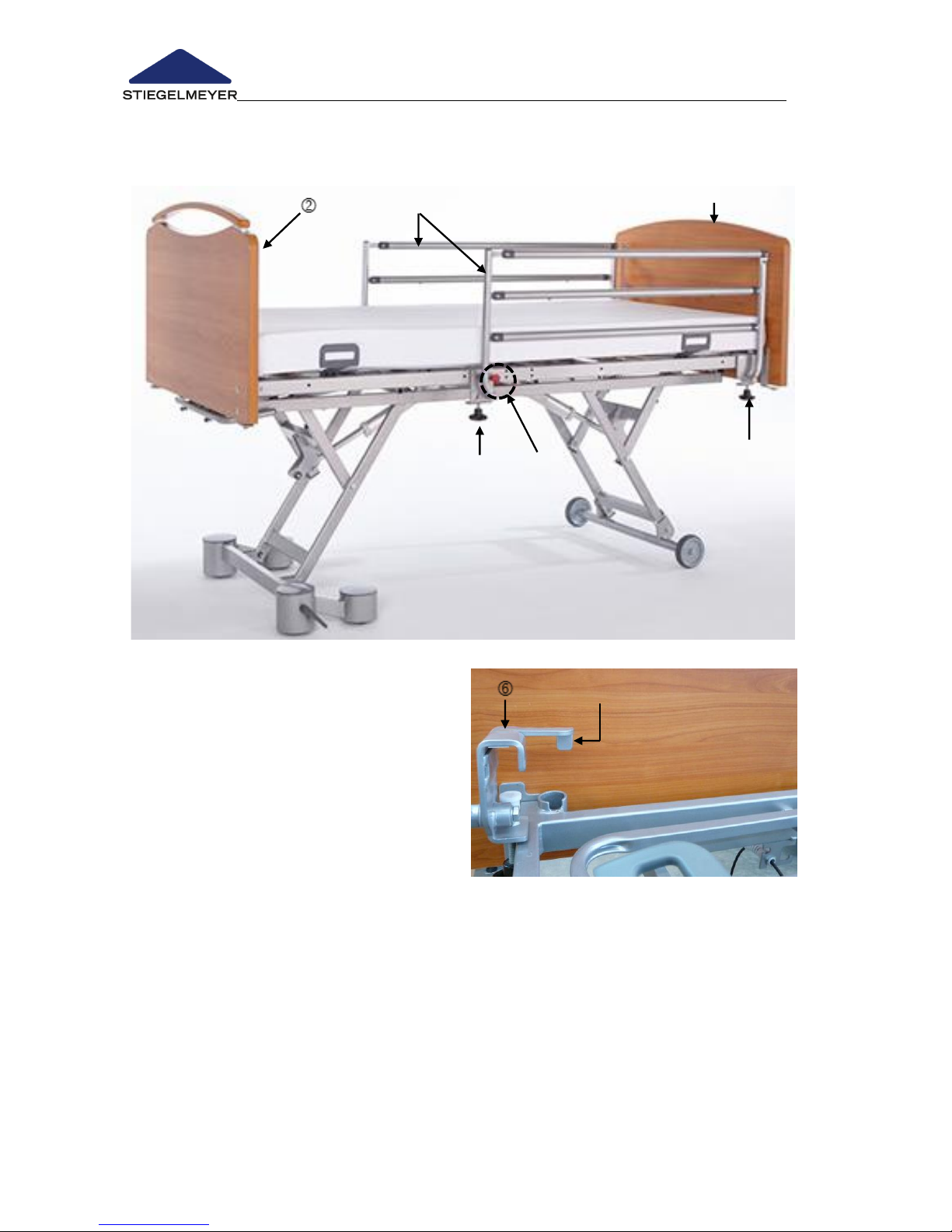
Instruction Manual for Care Bed Libra
Page 54 -
4.5.4 Swivelling safety sides *
Libra can also be equipped with a swivelling safety side.
Head end
Foot end
Swivelling safety sides
Star-head screws
Red release button
Clamping claw
Positioning guide
Assembly
When assembling the swivelling safety side, please note the following points:
The assembly is done at the head end (left and right).
Note the left safety side and the right safety side.
The side with the release button is at the middle of the bed.
The star head screw points downward.
Page 57
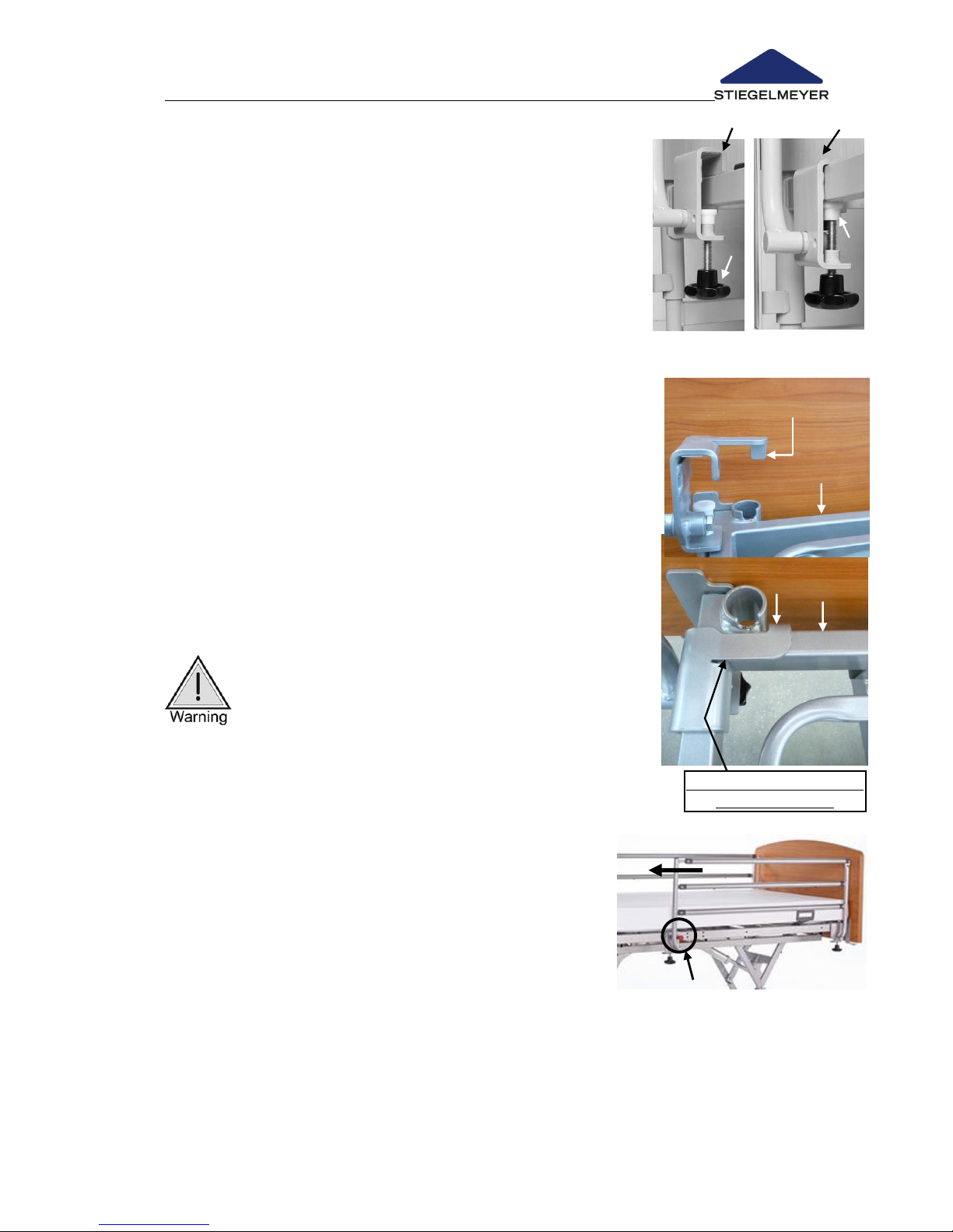
Instruction Manual for Care Bed Libra
Page 55
installed clamping claw -
required position
Install left safety side
Turn star head screws until they reach the stop.
o Now the clamping claw is completely open and
can grasp the mattress frame.
Bring the clamping claw to the long brace on the
mattress frame .
Push clamping claw downward .
o The head end of the clamping claw also has a
positioning guide for fixing the space between the headboard and
the safety side to approx. 6 cm.
o Caution! The positioning guide must be behind the cross brace on
the mattress frame during installation.
Turn the star head screw on both clamping claws tight
Lift the safety side until it clicks into place.
Check that the safety side sits firmly.
Install right safety side
Proceed analogously to installing the left safety side.
Operating the safety side
Attention: Risk of crushing! Watch your
fingers when raising and lowering the safety
side. They could become crushed between the
bed frame and the safety side!
Raising
Grab the safety side at the upper bar and swivel it
up in the direction of the headboard.
o The safety side is raised in a swivelling
movement and clicks audibly into place.
Check that the safety side is securely positioned
by sliding it back and forth.
Lowering
Hold the safety side firmly by the upper rail.
Press the red release button and swivel the safety side down and
towards the foot end.
Page 58
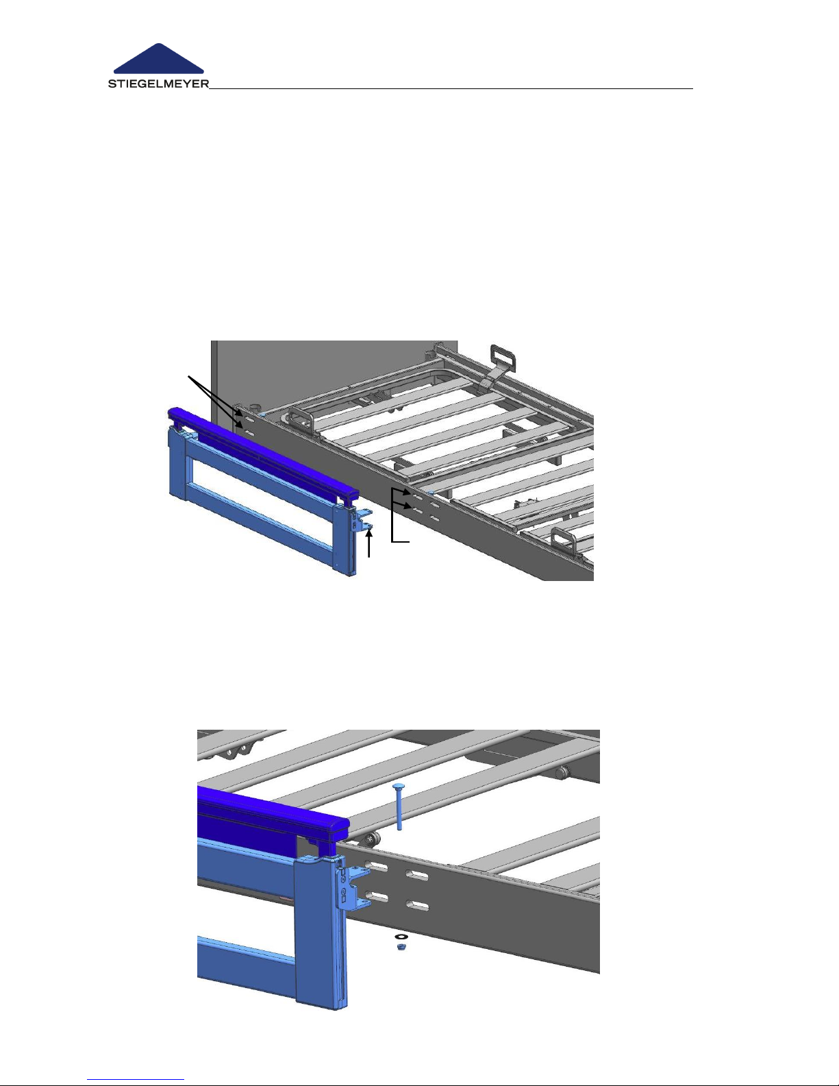
Instruction Manual for Care Bed Libra
Page 56 -
4.5.5 Split MobiFlex safety sides *
Libra can also be equipped with a MobiFlex safety side.
Assembly
Please note: The MobiFlex safety side comprises four parts.
Begin with the first part, for example, the left head side:
Insert fastening clamps through the slits on both side panels.
Insert the four screws provided into the fastening clamps from above (one
screw per fastening clamp).
Turn the washers and nuts onto the screws from below.
Page 59
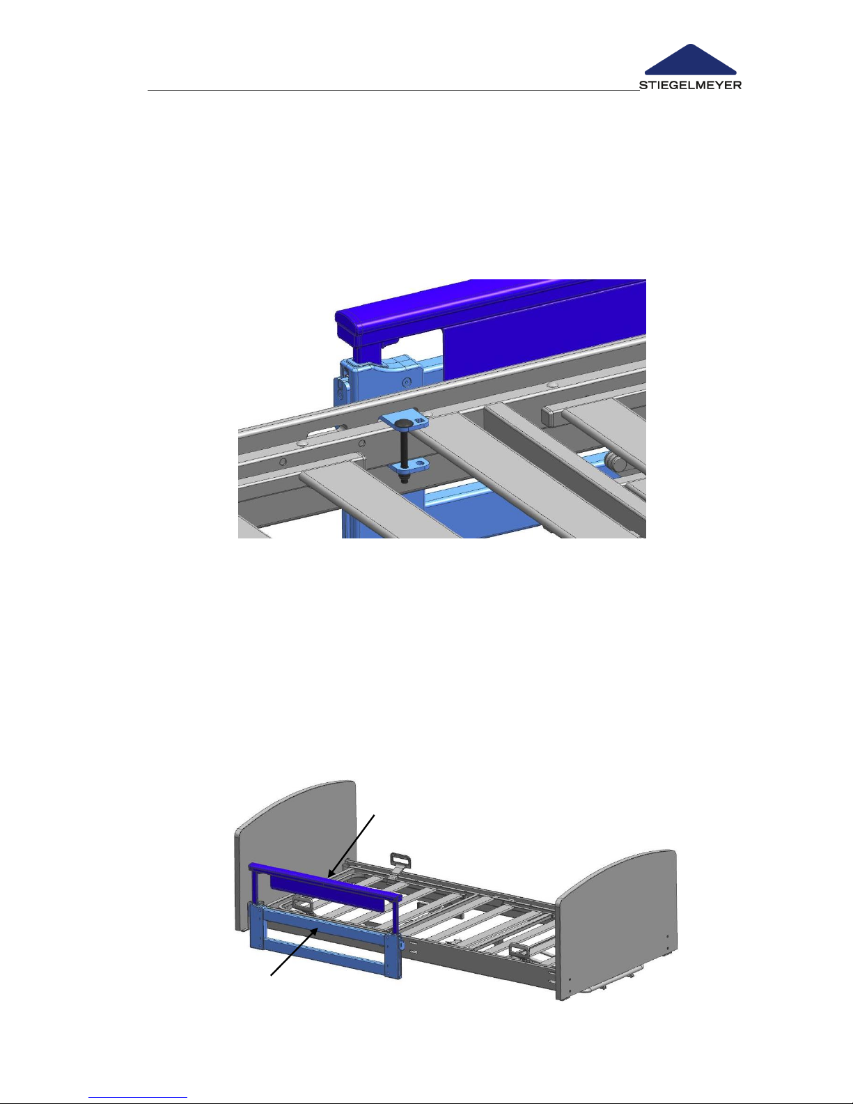
Instruction Manual for Care Bed Libra
Page 57
Tighten the screws (open jaw wrench size 13 mm).
o Caution! The fastening clamps must be centred in the slits at horizontal
level in the middle.
o Caution! The bearing surfaces of the fastening clamps must be flush
and parallel to the side panel.
Repeat this procedure with the remaining three parts of the MobiFlex
safety sides.
Operation
The MobiFlex safety sides can be easily raised and lowered and can be raised
into different positions.
Raising
Grab the upper bar with both hands and pull the safety side up as far as
the stop.
Repeat this procedure with the middle bar .
Page 60
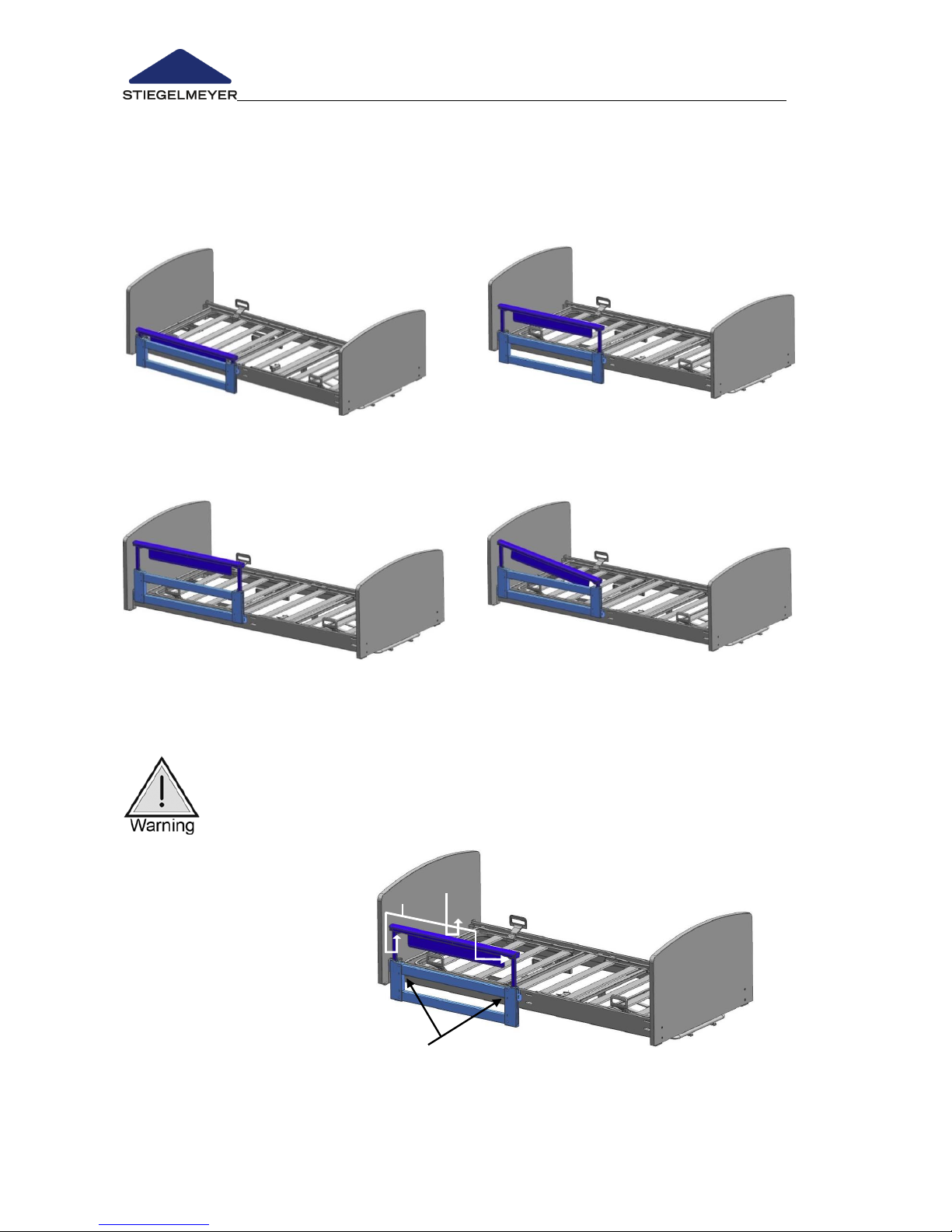
Instruction Manual for Care Bed Libra
Page 58 -
Possible raised positions
The following raised positions are possible with MobiFlex:
Completely lowered safety side
Raised upper bar
Completely raised safety side
Slanted raised upper bar
Lowering
The MobiFlex safety side can be lowered in two phases (telescopically).
Attention: Risk of crushing! Watch for your fingers when raising and
lowering the safety side. They can get crushed between the bed
frame and the safety side!
Proceed as follows:
Take pressure off of the
safety side first by gently
pulling up.
Then, press the two
release buttons on the
upper bars and lower
the safety side.
Repeat this procedure
with the middle bar (release button) .
Page 61

Instruction Manual for Care Bed Libra
Page 59
4.5.6 Variant - without safety side *
Libra beds can also be supplied without safety sides if the customer prefers.
Should it later be necessary to use a safety side, this can easily be fitted at a
later date.
There are two versions of safety sides to choose from:
Swivelling safety side :
Please refer to Chapter Fehler! Verweisquelle konnte nicht gefunden werden..
for more information on fitting and using swivelling safety sides.
Mobilflex safety side: In this case, attach suitable side panels (8) to match
the safety sides.
Please refer to Chapter Fehler! Verweisquelle konnte nicht gefunden werden..
for more information on fitting and using swivelling safety sides.
Page 62
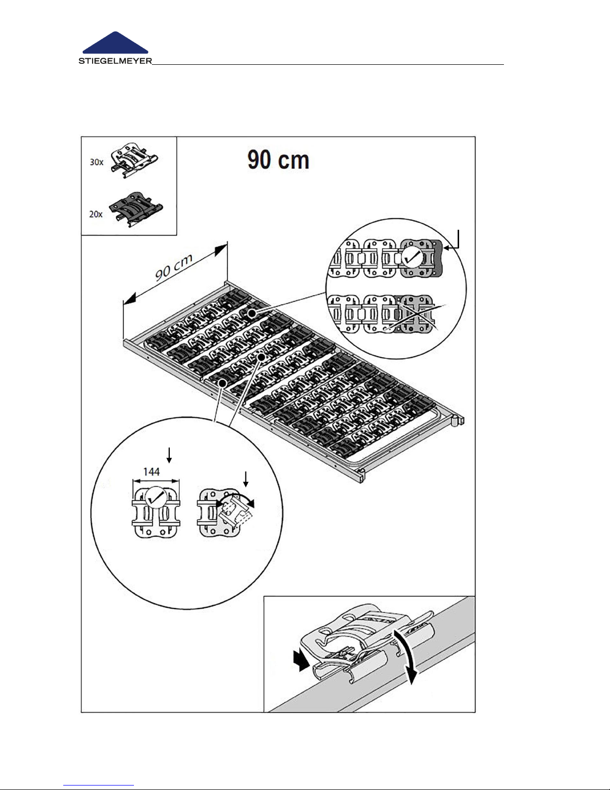
Instruction Manual for Care Bed Libra
Page 60 -
4.5.7 Comfort mattress base - width 90 cm *
Libra can also be equipped with a comfort mattress base. The following
installation guidelines refer to the 90 cm wide mattress base:
Wings of black elements facing
outwards .
Turn clips through 180° until 144
mm length visible .
Attach clips to the struts on the
mattress base and , with
white elements in the centre and
black elements at the edges.
Page 63
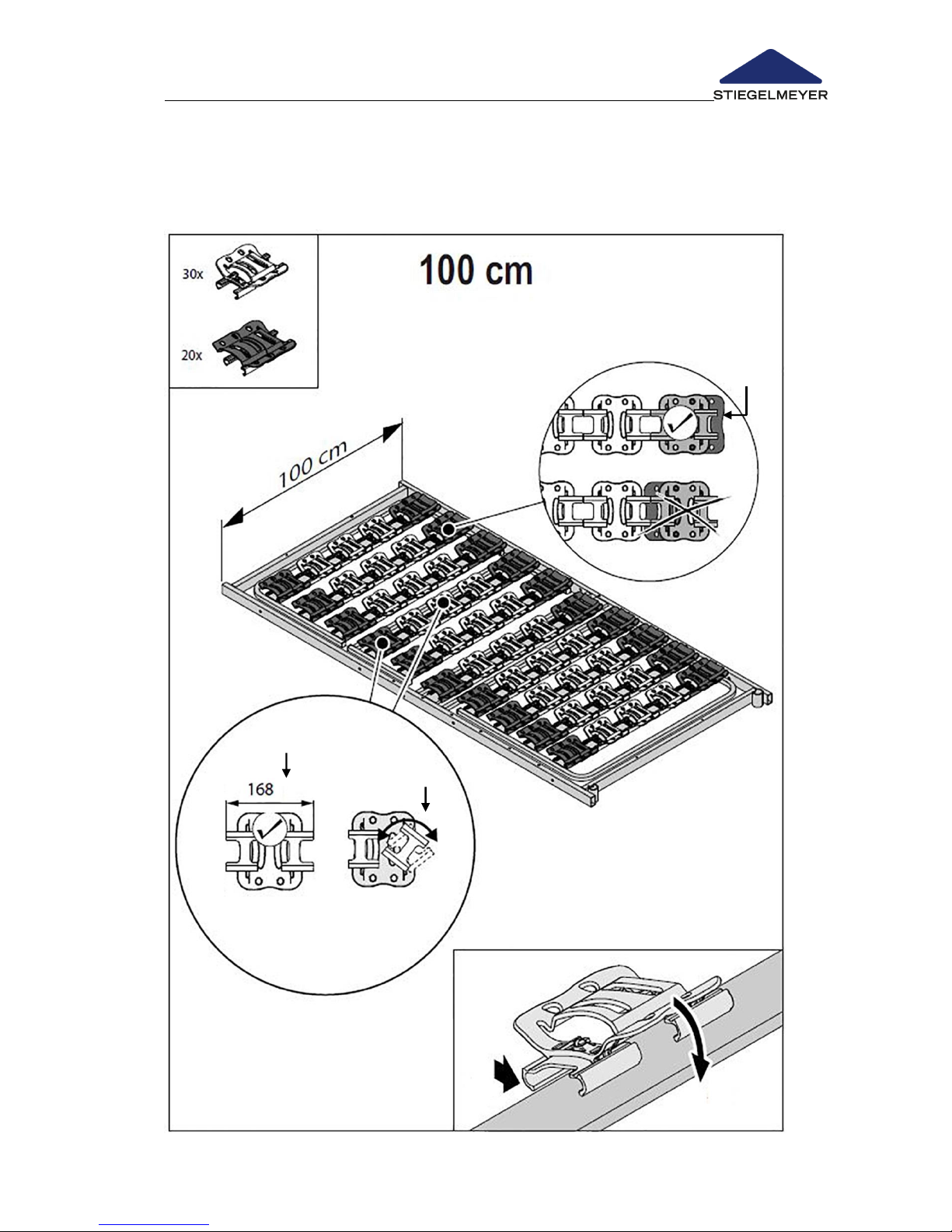
Instruction Manual for Care Bed Libra
Page 61
Wings of black elements facing
outwards .
Turn clips through 180° until 168
mm length visible .
Attach clips to the struts on the
mattress base and , with
white elements in the centre and
black elements at the edges.
4.5.8 Comfort mattress base - width 100 cm*
The following installation guidelines refer to the 100 cm wide mattress base:
Page 64
Instruction Manual for Care Bed Libra
Page 62 -
5 Cleaning and Disinfection
This bed cannot be machine washed and not suitable for
cleaning in a decontamination unit. It is suitable only for
manual cleaning and disinfection. To maintain the lifespan
and functionability as long as possible, you must observe the
advice in this chapter.
5.1 GENERAL INFORMATION ON CLEANING AND DISINFECTION
Cleaning is the most important measure and requirement for a successful
chemical disinfection.
When the bed is occupied by the same occupant, routine cleaning of the
bed is generally sufficient. Disinfection of the chassis is only necessary when it
has been visibly contaminated with infectious or potentially infectious
materials (blood, stool, pus) or, if in the presence of an infectious disease,
under doctor’s orders.
Before an occupant change, the bed must first be cleaned and disinfected by
wiping!
Before cleaning or disinfecting:
Unplug the transformer unit cable and store the mains plug so
that it does not come into contact with water or other cleaning
solutions.
There must be no external damages visible on any of the
electrical components. Not following this can lead to water or
cleaning solutions leaking into the electronics and causing
malfunctions or damages.
Before restarting the transformer unit, ensure that the electrical
contacts are free of any remaining moisture.
The electrical components must not be cleaned with a water
jet, a high pressure cleaner or other similar device! Clean only
with a moist cloth!
If you suspect that water or any other form of moisture has
penetrated the electrical components, pull the transformer unit
plug out immediately or do not plug it into the socket. If
already disconnected from the mains supply, make sure it is not
plugged in again. Report this immediately to the operator
responsible.
Failure to follow this safety advice could result in considerable
damage to the equipment and lead to subsequent malfunctions!
Page 65

Instruction Manual for Care Bed Libra
Page 63
5.2 CLEANING AND DISINFECTION INSTRUCTIONS
Remove bed linen and send it to the laundry service.
Clean all surfaces, including the slatted bed frame and mattress base
made of synthetic or metal slats, with a mild and environmentally
friendly cleaning agent. This also applies for the handset.
If the bed has been visibly contaminated with infectious or potentially
infectious materials, the bed should be subsequently disinfected by
wiping with one of the disinfection media approved by the DGHM
(Deutsche Gesellschaft für Hygiene und Mikrobiologie, German Society
for Hygiene and Microbiology) which is suitable for the corresponding
surfaces. The same applies for all beds with occupants who have
notifiable diseases according to § 6 of the Infektionsschutzgesetz (IfSG,
Protection against Infection Act), bacterial infections, or infections with
multiple-resistant pathogens (e.g. MRSA, VRE), as well as all beds in
intensive care stations and infectious disease clinics. For all disinfections,
the concentrations given in the DGHM list must be observed.
Disinfection of the castors is only necessary when they have been visibly
contaminated with infectious or potentially infectious materials.
Continuous disinfection is only necessary in hospitals when an
occupant has a multiple-resistant pathogen (e.g. MRSA).
Page 66

Instruction Manual for Care Bed Libra
Page 64 -
5.3 INSTRUCTIONS FOR THE USER AND EXPERT
In order to ensure that cleaning and disinfection are properly conducted, we
recommend that users and trained staff are appropriately instructed.
When providing instruction, observe the following points:
A clean bed must be transported in such a way that it will not become
dirty or contaminated.
Staff should be informed of the special measures required for cleaning
and disinfection and should carry out the procedure in a reliable
manner (the operator should specify the operational procedures or the
individual procedural steps). Care must be taken that only disinfection
agents approved by the DGHM (German Society for Hygiene and
Microbiology) are used, and that these are used only in the DGHM
approved concentrations.
The disinfectant must be suitable for the relevant surface.
For this activity, the expert should be provided with disposable aprons
and gloves which are impermeable to fluids.
For the cleaning treatment, only fresh, clean cloths may be used which
are subsequently sent to the laundry service.
When cleaning/disinfecting work has been completed, the staff must
disinfect their hands before carrying out other tasks.
An appropriate dispenser of hand sanitizers (with lifting dispensing
device) should be included in the equipment of the staff.
The immediate cleaning of the bed on site has the advantage that no
“dirty” beds or bed components come into contract with clean beds.
In this way, the transfer of potentially infectious germs which may be
found on the used chassis is prevented.
A transfer of germs in terms of a nosocomial infection can be safely
avoided by consistently and thoroughly following these
recommendations.
When the bed is not immediately reused, it should be stored (covered)
in such a way that it is protected from dust, inadvertent dirt and
contamination.
Page 67
Instruction Manual for Care Bed Libra
Page 65
5.4 CLEANING AND DISINFECTION AGENTS
Pay attention to the following recommendations to ensure that the bed
functions and usability are preserved as long as possible:
Do not use scouring agents, care products for stainless steel
and abrasive cleaning agents or scouring pads.
These substances can damage the surfaces.
Cleaning and decontaminating agents must have a pH value
of 5 to 8 at the specified concentrations.
The chloride content of the solutions prepared for use must not
exceed 100 mg/l.
We recommend (damp) wipe cleaning. When selecting
cleaning agents, ensure that the ones chosen are mild (gentle
to skin and surfaces) and environmentally friendly. A standard
household cleaner can generally be used.
Ensure that after cleaning / disinfection no residues remain on
the surfaces of the bed. Otherwise the surfaces may become
damaged in the long term in these areas.
Despite the excellent mechanical resistance, scratches,
markings, etc., which permeate the entire coating should be
resealed using a suitable repair medium to prevent the
penetration of moisture. For further information, consult
STIEGELMEYER or a specialist of your choice.
Page 68

Instruction Manual for Care Bed Libra
Page 66 -
As a rule, aldehyde-based disinfection media have the
advantage that they have a wide range of impact, a
relatively low protein effect and are environmentally friendly.
The main disadvantage of these agents is their potential to
cause allergies and irritation.
Glucoprotamine-based formulations do not have this disadvantage
and are equally effective, although most are somewhat more
expensive.
Disinfection media based on compounds which could potentially
release chlorine may be corrosive for metals, synthetics, rubbers and
other materials over longer contact periods or when concentrations
are too high. Furthermore, these media have a higher so-called
protein effect, are mucous membrane irritants and demonstrate poor
environmental compatibility.
For disinfection by wiping, most cleaning and disinfection agents
usually used in hospitals or care facilities, such as cold and hot water,
detergents, alkaline solutions and alcohols, can be used.
These agents may not contain any substances that could change
the surface structure or the adhesive properties of the plastic
materials.
The choice of cleaning agents and disinfectants available on the
market may change from time to time. Stiegelmeyer therefore
routinely tests the most commonly used materials for compatibility.
The most up-to-date list of cleaning agents and disinfectants can be
obtained on request.
Our German service centre:
Stiegelmeyer GmbH & Co. KG
Ackerstrasse 42, 32051 Herford, Germany
Phone: +49 (0) 5221 185-0
Fax: +49 (0) 5221 / 185-219
E-mail: [email protected]
www.stiegelmeyer.com
Customers outside Germany are requested to contact our
distribution companies in their particular country if they have any
questions. Contact details can be found on our website.
Page 69

Instruction Manual for Care Bed Libra
Page 67
5.5 HANDLING CLEANING AND DISINFECTION AGENTS
Pay attention to the exact dosage! We recommend the use of
automated dosing instruments.
Always prepare solutions with cold water in order to avoid the
formation of vapours which are mucous membrane irritants.
Wear gloves, in order to avoid direct skin contact.
Do not keep prepared surface disinfection solutions in open containers
with floating cleaning cloths. Be sure to cover all containers!
Use sealable bottles with pump dispensers for moistening the cleaning
cloths.
Ventilate the room after the disinfection has been completed.
Disinfect by wiping; do not disinfect by spraying! When spraying, a large
portion of the disinfection medium is released as spray and could be
inhaled.
Furthermore, the wiping effect plays a significant role.
Do not use alcohols for the disinfection of large surfaces.
Page 70
Instruction Manual for Care Bed Libra
Page 68 -
6 Maintenance
Legal Principles
Operators of beds in Germany are obliged in accordance with
German Medical Devices Operator Ordinance § 4 (Maintenance)
DGUV 3 (Testing of Mobile Electrical Equipment in
Commercial Use) of the German Social Accident Insurance
to preserve the safe operating condition of medical devices throughout their
entire service life. This also includes regularly carrying out expert maintenance
as well as safety checks.
In other countries outside Germany or the EU, the relevant national
regulations must be complied with.
Information for the Operator
This bed has been designed and built to work safely over a long period of
time if operated correctly and put to proper use.
As a result of repeated transport and assembly and dismantling,
improper operation as well as long-term use, damage, defects
and signs of wear may occur. These deficiencies can cause
hazards if they are not recognised and corrected immediately.
For this reason there are legal principles for conducting regular inspections in
order to guarantee the safe condition of this medical product.
According to § 4 of the Medical Devices Operator Ordinance
(Medizinprodukte-Betreiberverordnung) it is the responsibility of the operator
to maintain this product. For this reason, the regular inspections and
functional checks described hereafter must be performed by both the
operator as well as the users.
This bed must not be modified without authorisation by the manufacturer.
Instruct users about the following inspections that are required to be
performed! (see Chapter 6.1).
Page 71
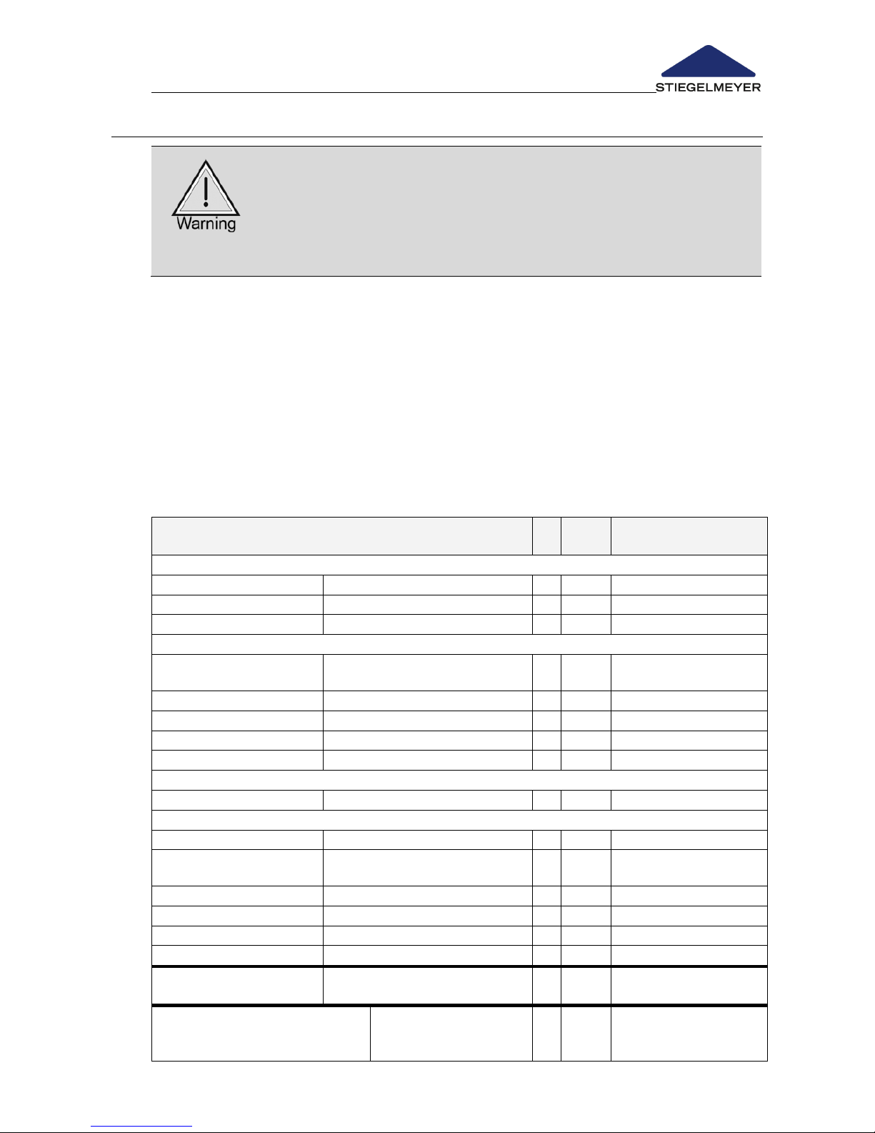
Instruction Manual for Care Bed Libra
Page 69
6.1 BY THE USER
If damage or a malfunction is suspected, the bed must be
withdrawn from service immediately and disconnected
from the mains supply until the defective parts have been
repaired or replaced!
Contact the operator who is responsible for you if the
defective parts need to be replaced or repaired.
Besides the regular comprehensive inspections by qualified technical staff,
the user (care personnel, care-giving relatives etc.) must also carry out a
minimum of visual inspections and functional checks at short, regular intervals
and before use by a new patient.
Recommendation: Inspect all electrical and mechanical components once a
month. In addition, the transformer unit with cable and the handset cable
must be inspected each time that they have been subjected to mechanical
strain and after each move to a new location.
Checklist: Inspection by the User
Inspection
What to check? Check for?
ok
Not
ok
Description of defect
Visual inspection of the electrical components
Handset, handset cable
Damage, routing of cable
Transformer unit
Damage, routing of cable
Handset
Damage, foil
Visual Inspection of the Mechanical Components
Patient lifting pole,
location sleeves
Damage, deformation
Chassis
Damage, deformations
Wooden framing
Damage, splinters
Mattress base frame
Damage, deformations?
Safety side bars
Damage, splinters
Performance Check of the Electrical Components
Handset
Function test, locking functions
Performance Check of the Mechanical Components
Castors
Braking, running
Emergency lowering of
backrest
Test according to manual
Screws and bolts
Fixed position
Safety side
Safe locking, unlocking
Lower leg rest
Engage
Motor bolts
Fixed position
Accessories (e.g. lifting
pole, handle)
Fastening, damage
Inspector’s signature:
Inspection results:
Date:
Page 72

Instruction Manual for Care Bed Libra
Page 70 -
6.2 BY THE OPERATOR
The operator of this care bed is obliged according to MPBetreibV (Medical
Devices Operator Ordinance) Section 4 to conduct regular inspections in
each new building, after each maintenance and during operation to ensure
the safe condition of the care bed.
These inspection are to be repeated within the regular maintenance activities
depending on the conditions of use according to MPBetreibV Section 4 and
the inspections prescribed by the Employers' Liability Insurance Associations
for mobile electrical equipment in commercial use according to DGUV A3
(Testing of Mobile Electrical Equipment in Commercial Use).
Inspection Interval
We recommend, as a guideline, that an annual DGUV A3 inspection be
carried out by our qualified service engineers, with verification of adherence
to the 2% error rate (see also the DGUV A3 accident prevention regulations: §
5, Table 1B).
Observe the sequence order for the inspection according to EN 62353 (VDE
0751):
I. Visual inspection
II. Electrical measurement
III. Performance inspection
Visual and functional check
- The visual inspection and function testing as well as the assessment and
documentation of the test results must be conducted exclusively by
competent persons, according to MPBetreibV Section 4 and DIN EN 62353
(VDE 0751), who have the required qualifications and tools for proper
inspections and testing.
Electrical measurement
- The electrical measurement according to VDE 0751 may also be
conducted by electrically instructed persons (in the sense of DGUV A3) with
additional medical and device-specific if appropriate measuring
instruments are present.
- The assessment and documentation of the test results may only be made
by a qualified electrician with medical and device specific additional
knowledge.
Page 73

Instruction Manual for Care Bed Libra
Page 71
Transformer unit
Preparation:
o Unplug the transformer unit plug of the plug-in power pack from the
wall mains socket.
o Insert the transformer unit plug of the plug-in power pack into the test
socket on the testing device.
Test procedure:
o Make the following selections on the instrument: Leakage current test,
direct or differential current, in accordance with DIN EN 62353
o Conduct a leakage current test according to the information of the
instrument manufacturer.
Threshold:
o Leakage current I
Abl
smaller than 0.1 mA.
Test cycles
Visual and functional check: yearly
Electrical measurement yearly
We recommend the inspection cycles indicated. In the case of verifiable
compliance with 2 % error rate (also see DGUV 3: §5, Table 1B), the inspection
cycle can be extended to a maximum of 2 years on the operator's
responsibility.
If damage or a malfunction is suspected, the bed must be
withdrawn from service immediately and disconnected from
the mains supply until the defective parts have been repaired
or replaced!
Page 74
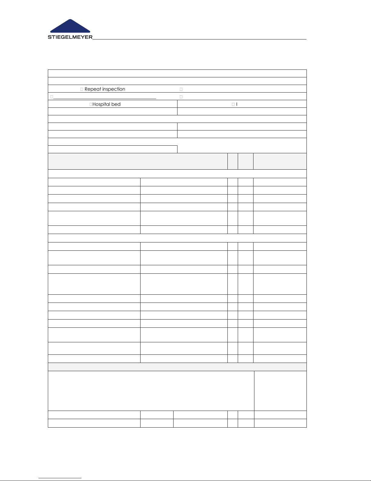
Instruction Manual for Care Bed Libra
Page 72 -
Inspection Report following an inspection of electromedical equipment according
to DIN EN 62353 (VDE 0751-1): 2015-10 - Page 1 of 3
Customer / med. facility / practice:
Address:
Carried out: Inspection prior to initial operation (reference value)
Inspection following repairs/servicing
Type of device: Care bed
Protection class: II
Bed type: Libra
Inventory number:
Location:
Transformer unit number:
Serial number:
Manufacturer: STIEGELMEYER GmbH & Co. KG
User-specific parts: None
Testing equipment used (type/inventory no.): 1.
Medical Devices Act classification: Class I,
2.
I. Visual inspection
What to check... Check for?
ok
Not
ok
Description
of defect
Visual Inspection of the Electrical Components
Stickers and type plates
Present, legible
Control unit housing
Correct position, damage
Motor housing and lifting tubes
Correct position, damage
Handset
Damage, foil
Motor cable, handset cable, mains
cable, connecting cable
Damage, routing of cable
Plug and plug cover on control unit
Available, correct position
Visual Inspection of the Mechanical Components
Stickers and type plates
Present, legible
Patient lifting pole, sleeve; grab
handles
Damage, deformations
Chassis
Damage, deformations
Bowden cable, emergency
lowering
backrest
Routing, spots with kinks
Castors
Damage
Mattress base
Damage, deformations
Wooden framing
Damage, splinters
Welded seams
Split welded seams
Safety sides: Bars
Damage, splinter, dimensions
acc. to Sheet 3
Connecting elements (screws,
bolts, nuts, safety caps)
Fixed position, completeness
Wearing parts, such as joints
Damage
II. Electrical measurement
Leakage current of device, direct/difference
1. Plug the mains cable / plug-in power pack in the test socket of the
measuring instrument.
2. Connect sensor to plain screw in the mattress base frame.
3. For the duration of the measurements, activate the motors using the handset
4. Start measurement procedure on the measuring instrument
Threshold
Measured value
Result: Bed prot. class II (type B)
0.1 mA
mA
Page 75
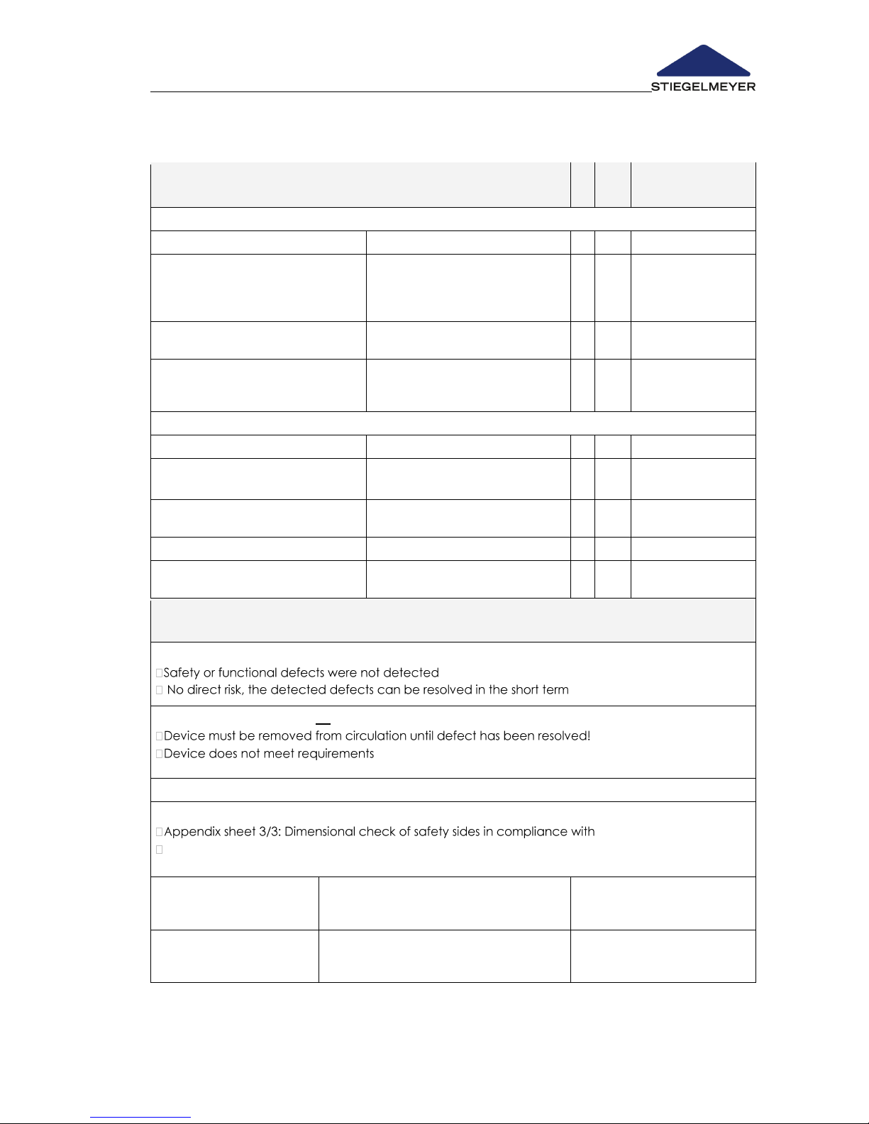
Instruction Manual for Care Bed Libra
Page 73
Inspection Report following an inspection of electromedical equipment
according to DIN EN 62353 (VDE 0751-1): 2015-10 - Page 2 of 3
III.Performance inspection
What to check? Check for?
ok
Not
ok
Description
of defect
Performance Check of the Electrical Components
End of travel cut-out for motors
Automatic cut-out
Handset, operating elements,
external transformer
Test according to instruction
manual: Locking functions; key
functions; no "rattling“ when
shaken
Motors
No abnormal noise development
(rattling, uneven running, etc.)
Installation of cable harness and
proper seat of plugs and strain
relief
Secure attachment, firm seat
acc. to operating instructions
Performance check of the mechanical components
Joints and pivots;
Smooth operation
Castors
Brakes, securely engaged
brake
Safety sides
Safe engagement, unlocking
acc. to operating instructions
Lower leg rest
Engage
Accessories (e.g. patient lifting
pole, grab handle)
Secure attachment, without
damage, suitability for bed
Inspection results:
Inspection passed; test approval sticker applied:
Inspection was not passed; no test approval sticker applied:
– modification / replace components / decommissioning is
recommended!
Next inspection date:
Documents that form part of this inspection report:
statutory regulations:
Inspected on:
Inspected by:
Signature:
Evaluated on:
Operator/Expert:
Signature:
Page 76
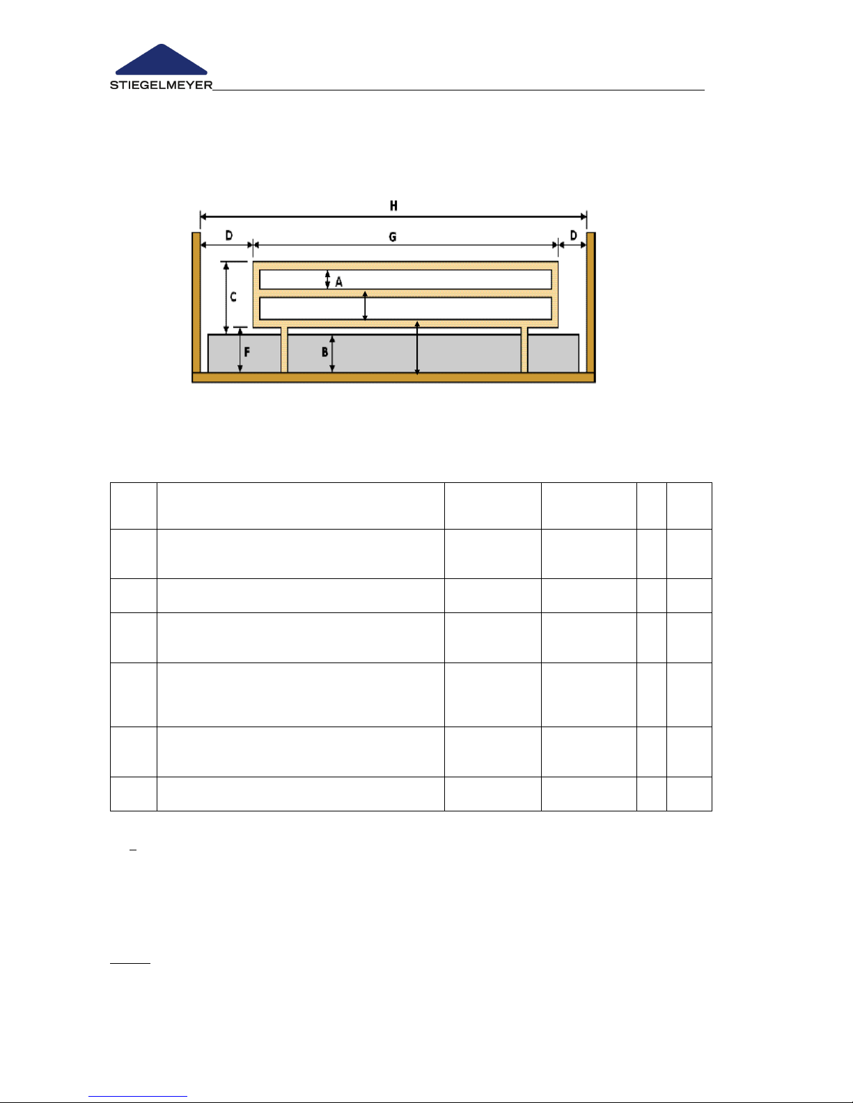
Instruction Manual for Care Bed Libra
Page 74 -
Inspection Report following an inspection of electromedical equipment
according to DIN EN 62353 (VDE 0751-1): 2015-10 - Page 3 of 3
Dimensional check of safety sides in compliance with statutory regulations:
Dimensions of a one-piece safety side
When measuring the distances, the dimensions resulting from likely
mechanical loads are decisive!
Item
Description of dimensions
Nominal
Actual
ok
not
ok
A
The greatest dimension in at least one
direction between components of the safety
side/grab handle in all normally used positions.
A ≤ 120 mm
B
Thickness of the normally used uncompressed
mattress as indicated by the manufacturer
B ≤ 120 mm**
C
Height of the upper edge of the safety sides
above the uncompressed mattress and the
bed base in a level position
C ≥ 220 mm
D
Distance between the headboard/footboard
/accessories and safety sides/grab handle with
the bed base in a level position. Also applies in
the case of an extended foot section.
D ≤ 60 mm or
D ≥ 318 mm *
F
The greatest dimension in at least one
direction of each opening under the safety
sides
F ≤ 120 mm
G
Length of the safety side(s)
G ≥ 50% H
G = H **
G > 50%H***
x
*Data from Stiegelmeyer modified in view of expected new bed directive IEC 60601-2-52.
D > 318 mm is only admissible at foot end of bed!
** Data from Stiegelmeyer supplemented for the existing continuous safety side configuration.
*** Data from Stiegelmeyer supplemented for the existing split safety side configuration with at least the
safety sides at the head end raised (if completely raised at head and foot ends, this corresponds to a
one-piece safety side; see **)
Source: Bavarian State Ministry for Health, Nutrition and Consumer Protection, Dept. 5, Schellingstr.
80797 Munich; www.stmgev.bayern.de; email: [email protected]
A
A
Page 77
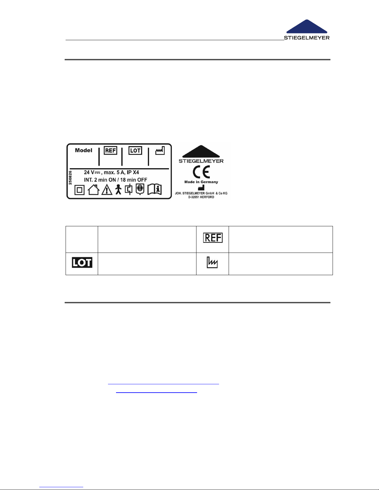
Instruction Manual for Care Bed Libra
Page 75
6.3 REPLACEMENT PARTS
In order to maintain operational safety and the right to claim under warranty,
only original Stiegelmeyer replacement parts may be used!
For quick and easy ordering of replacement parts we need you to give us the
customer number
as well as the following other details that are indicated on the type tag at the
head end of the bed frame (inner side).
Required information:
Model
Name of product
Item number
Order number
Date of manufacture
(week/year)
6.4 SERVICE ADDRESS
To order replacement parts in Germany and for any customer service
requirements or other questions, please contact our service centre:
Stiegelmeyer GmbH & Co. KG
Ackerstrasse 42, 32051 Herford, Germany
Phone: +49 (0) 5221 185-777
Fax: +49 (0) 5221 / 185-219
Email: [email protected]
Internet: www.Stiegelmeyer.com
Customers outside Germany can contact our sales distributors in the
respective country if they have any questions. Contact details can be found
on our website.
Page 78
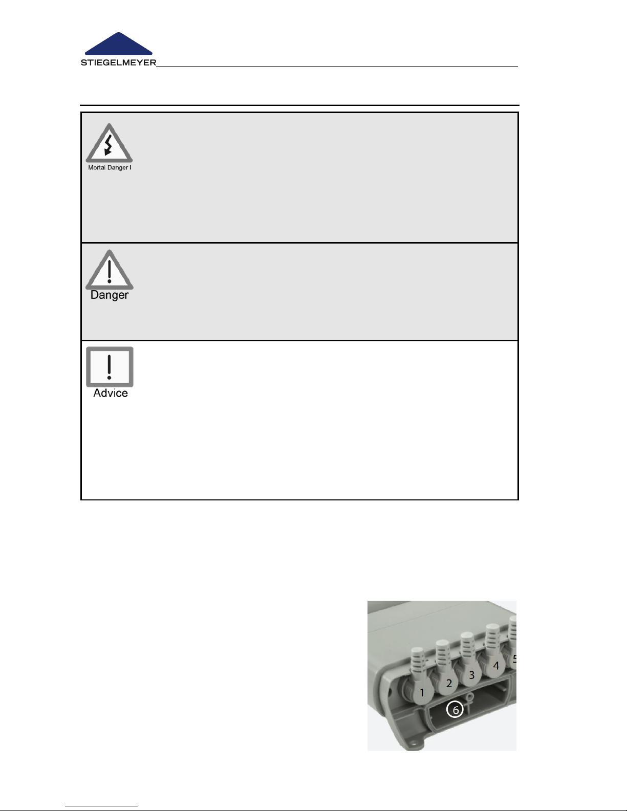
Instruction Manual for Care Bed Libra
Page 76 -
6.5 REPLACEMENT OF ELECTRICAL COMPONENTS
Danger of death due to electric shock!
Before commencing any work, unplug the transformer unit
cable from the electrical socket!
Any work and/or repairs to the electrical drive system may
only be carried out by the Stiegelmeyer service engineers,
the drive manufacturer or qualified and authorised
electricians in compliance with all the relevant VDE and
safety regulations!
Only dismantle the control unit and electrical motors when
the bed is in the home position (mattress base is in the
horizontal position). Otherwise there is the risk of being
crushed due to falling parts of the mattress base.
On no account should the user attempt to rectify
malfunctions in the electrical system!
- All the drive components are maintenance-free and must not
be opened. In the event of a malfunction, the corresponding
components should always be replaced in full!
- When replacing individual components, always make sure that
all plugs are equipped with undamaged O-rings. The plugs
have to be aligned in accord with the sockets of the control
unit and have to be plugged in all the way. Finally the plug
cover has to be properly fastened again. Only this ensures
tightness and efficient function. Only this ensures tightness and
proper function.
6.5.1 Plug assignment of the control unit
All plugs are connected to the control unit. To prevent the plugs from being
inadvertently disconnected, they are secured with a cover. When necessary,
this device can be carefully lifted off using a screwdriver.
1 = Handset
2 = Lift motor foot section (white)
3 = Lift motor head section (blue)
4 = Thigh rest (yellow)
5 = Backrest motor (black)
6 = Battery compartment (2 x 9 Volt batteries)
Page 79
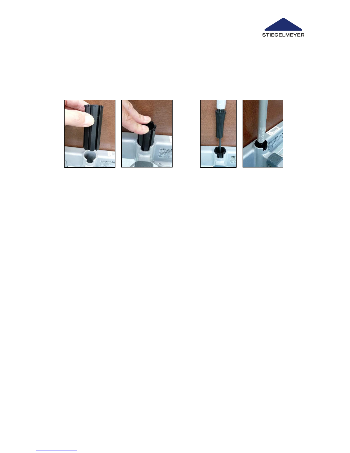
Instruction Manual for Care Bed Libra
Page 77
6.5.2 Connection of a reading lamp (optional equipment)
The reading lamp is installed as follows and then connected with the plugpower pack to an external 230 Volt outlet.
Please read the separately enclosed instruction manual on how to operate it.
Step 1
Step 2
Insert the plastic adaptor securely
into the sleeve for the patient lifting
pole at head end (left or right).
Insert the upright pole of the lamp
with the connecting cable from
above into the plastic adaptor and
press it down until it is firmly in place.
6.5.3 Control unit replacement
Unplug the transformer unit plug from the socket.
Carefully unscrew the plug cover on the control unit off using a Philips
screw driver.
Mark the plug positions to avoid switching them when re-assembling
(see Chapter 6.5.1).
Unplug all plugs / connecting cables from the control unit.
Remove the old control unit from its holder.
o Remove the two clamps on the holder.
Place the new control unit in and fasten it with the help of the clamps.
Insert all plugs again into the corresponding outlets (see Chapter 6.5.1).
o Pay attention that the plug O-rings are all present and undamaged. It
seals the plug within the control unit.
When routing the handset cable, ensure that it cannot be damaged by
any moving parts of the bed.
Put the plug cover back in place. This prevents all the plugs from being
pulled out of the control unit.
Lower the bed completely down or raise it up. That allows the bed's
control system to detect the intermediate stops.
After this, check the power adjustment functions according to Chapter
6.2!
Page 80

Instruction Manual for Care Bed Libra
Page 78 -
6.5.4 Motor replacement
Unplug the transformer unit plug from the socket.
Remove the faulty motor.
o For lift motors: Remove the safety disk and extension bolts.
o For upper thigh and back motors: Remove clevis pins.
Loosen the plug-in cable connection on the control unit.
Reinstall the new motor in exactly the same way.
To prevent the motor bolts from working loose and causing potentially
hazardous sudden changes in the position of the bed, always ensure that
you fit new safety caps (“Starlock”; available from Stiegelmeyer service
department) and do not refit the old safety caps that you removed.
After this, check the power adjustment functions (see Chapters 6.2).
6.5.5 Decommissioning
If the bed is not used for an extended period, please follow the instructions
below for taking the bed out of service safely and ensuring ideal conditions
for its re-use.
Clean and disinfect the bed (see Chapter 5) and cover it as a protection
against new contamination.
Adjust the mattress base to a flat home position at its lowest level.
Lock the electric adjustment functions to prevent them from being
activated accidentally or by unauthorised persons.
The bed must be braked.
Pay attention to the ambient conditions required for storage (see Chapter
9.3).
Page 81

Instruction Manual for Care Bed Libra
Page 79
7 Troubleshooting
The following table is a guide for rectifying common malfunctions. Should a
malfunction occur that is not included in the table, inform your operator.
Problem
Possible causes
Solution
Handset/
Drive system
not functioning
(bed is connected
to mains power
supply)
Transformer unit is not or not
properly plugged in
No power supply to socket
Functions are locked on
handset
Handset, transformer unit
cable or control unit is
defective
Insert transformer unit
cable; green LED must
light up on the
transformer unit.
Check socket and fuse
box
Release functions (see
Chapter 4.3.5)
Inform your operator
about any necessary
repairs
Green LED on
transformer unit
does not light up
and drive system is
not functioning
Transformer unit is not
properly plugged in
No power supply to socket
Transformer unit damaged
Transformer unit is not
properly plugged in
Plug in transformer unit
Check socket
Replace transformer.
Inform your operator about
necessary repairs
Yellow LED does
not light up when
key is pressed on
handset and the
drive does not
respond
Functions locked on handset
Handset faulty
Release functions (see
Chapter 4.3.5)
Replace handset
Handset not
functioning,
adjustments are not
locked
Handset faulty
Control unit has detected a
fault and for safety reasons
has locked the adjusting
functions
Replace handset
Unplug transformer unit
from the outlet, wait at
least 10 sec. and then plug
the transformer unit back
in.
Operation is not
possible despite
proper power
supply
Control unit has shut down
due to overheating
Control unit has detected a
fault and for safety reasons
has locked the adjusting
functions
Control unit defective
Observe max. duty cycle:
intermittent duty 2 min
ON/18 min OFF; replace
the control unit.
Unplug transformer unit
from the outlet, wait at
least 10 sec. and then plug
the transformer unit back
in.
Exchange control unit
Inform your operator
about any necessary
repairs
Page 82

Instruction Manual for Care Bed Libra
Page 80 -
Problem
Possible causes
Solution
Continuous or
longer signal sound
without handset
activation
Controller is defective
Inform your operator
about any necessary
repairs
Individual drives
only go in one
direction
Defective handset, drive unit
or control unit
Inform your operator
about any necessary
repairs
Manual emergency
lowering of
backrest is not
possible
Bowden cable is too loose or
not secured
Bowden cable is kinked
Readjust at the release
lever or secure
Install new Bowden
cable. Inform your
operator about any
necessary repairs
Drive runs for a brief
time only, then
stops
Drive overloaded
Structural obstructions in the
way of bed adjustment
Remove the overload in
the bed, retest
Remove obstructions;
move bed away from
obstructions (e.g. window
sills, sloping roofs)
Control unit partly
not functioning
One or more motors are not
connected/ electrical plug
connections are
disconnected
A serious error has occurred
in the control unit and
blocked all functions for
safety reasons.
Check electrical
connection and all
motors/plug-in
connections;
Have actuator system
checked.
Inform the operator in order
to arrange for repairs
Page 83
Instruction Manual for Care Bed Libra
Page 81
8 Accessories
A wide range of accessories is available for this bed, and we are continually
extending this range
Risk of Injury
Efficient and safe operation combined with maximum
protection of patients can only be guaranteed if original
Stiegelmeyer accessories are used which are designed for the
relevant model of bed.
In addition to the information given in this instruction manual,
please also refer in this respect to the separate special
instruction manual supplied with certain accessories.
Make sure that the arrangement of accessories does not
produce any crush or shearing zones for the resident when the
backrest and leg rest are adjusted.
If this cannot be guaranteed, the user must safely prevent the
occupant from adjusting the backrest and leg rest.
Place the handset out of reach (e.g. at the foot end of the
bed) or lock the handset adjustment options.
Preventing damage to property
In order to minimise any potential damage to property, please
read and refer to the following general information on selecting
and attaching accessories:
Attach accessories only while these are required and only at
the positions intended for them in such a way as to avoid
damaging the surfaces of the bed and accessories.
Avoid, for example, chafing or unprotected attachment of
metal clamps on coated or varnished surfaces.
Please note when moving the bed that attached accessories
may extend beyond the height, width or length of the bed
and so may collide more easily with door frames, corners of
walls and other obstructions.
In the case of very long accessories such as patient lifting poles,
infusion poles, extensions, mobilisation aids, etc., avoid applying
high lateral forces, such as are possible with this bed design,
such as by manoeuvring the bed using the infusion pole. This
will prevent overloading the fixing points.
Lists of accessories can be obtained from Stiegelmeyer and their sales
partners, quoting the bed model.
Patient lifting pole with
grab handle
LED reading lamps,
various
Protective covers for
safety sides
Infusion stand/holder
Wall spacers
Page 84
Instruction Manual for Care Bed Libra
Page 82 -
9 Technical Data
9.1 DIMENSIONS AND WEIGHTS
Mattress base (LxW)
approx.
200 x 90 cm (Standard)
200 x 100 cm (Optional)
(Optional feature: 220 x 90 cm) bed extension
Total weight
135 kg
Safe working load
225 kg
External dimensions
(LxW) approx.
209.4 x 100.3 cm (for mattress base widths of 90 cm)
209.4 x 110.3 cm (for mattress base widths of 100 cm)
9.2 ELECTRICAL DATA
Control unit
Type
ECS
Operating voltage
29 V DC
Output current
max. DC 8.5 A
Duty cycle
Intermittent duty, 2 min ON / 18 min OFF
Protection category
IPX 54, splash-proof
Classification
Protection Class III, Type B, MPG classification
Class I, not for use in environments where there is a
risk of explosion
Transformer unit
Type
SMPS 15
Input voltage
100-240 V
max. current input
AC 1.5 A
Output voltage
29 V DC
Standby consumption
< 0,5 W
Output current
5.5 A (max. 8.5 A)
Duty cycle
Intermittent duty, 2 min ON / 18 min OFF
Protection category
IPX 54, splash-proof
Classification
Protection Class II, Type B, MPG classification Class I, not
for use in environments where there is a risk of explosion
Page 85
Instruction Manual for Care Bed Libra
Page 83
Handset
Type
DEWERT IPROXX II
Protection category
IP X6
Electric motor for mattress base height
Type
DEWERT Megamat 2
Power/stroke
6.000 N / 250 mm
Input voltage
24 V DC
Protection category
Intermittent duty: 2 min ON / 18 min OFF
Duty cycle
IP x4
Electrical motor for backrest
Type
DEWERT Megamat 2
Power/stroke
4.000 N / 200 mm
Input voltage
24 V DC
Protection category
Intermittent duty: 2 min ON / 18 min OFF
Duty cycle
IP x4
Electrical motor for thigh rest
Type
DEWERT Megamat 2
Power/stroke
4.000 N / 70 mm
Input voltage
24 V DC
Protection category
Intermittent duty: 2 min ON / 18 min OFF
Duty cycle
IP x4
Noise level
Noise level during adjustment
max. 48 dB(A)
Page 86
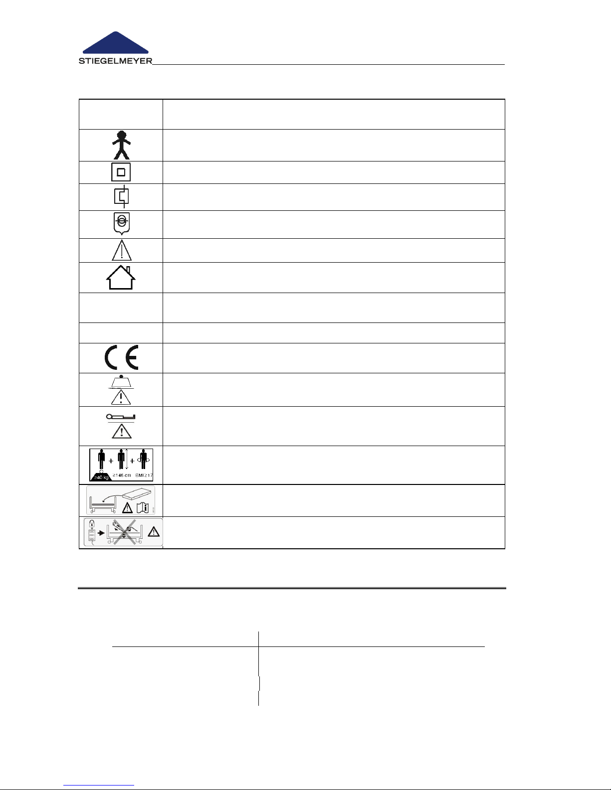
Instruction Manual for Care Bed Libra
Page 84 -
Explanation of the graphical symbols used
Symbol
Meaning
Device with type B application component in accordance with
EN 60601-1 (special protection against electric shock)
Protection Class II device, shock-proof
Transformer with thermal fuse
Safety transformer to VDE 0551
Attention! Pay attention to the instruction manual
Only for use in enclosed spaces - do not use outdoors
IP x4
Protection of electrical equipment from splash water from all sides
IP x6
Protection of electrical equipment from strong water jets
Mark of conformity in accordance with the Medical Device
Directive 93/42, EEC Appendix VII
Safe working load (= max. permissible weight of patient, mattress
and all accessories attached)
Max. weight of patient (= max. permissible weight of patient; this is
dependent on the total weight of all the accessories attached to the
bed and is always less than the safe working load)
Minimum patient sizes/weight: height: 146 cm,
weight: 40 kg; Body Mass Index1 “BMI”: 17
Only use mattresses that are approved by the manufacturer.
Lock the handset if the patient could be at risk should electrically
operated adjustments be made unintentionally
9.3 AMBIENT CONDITIONS
The following ambient conditions must be maintained:
In storage/ Transport
Minimum
Maximum
Storage temperature:
-20°C
+50 °C
Relative humidity :
50 %
70 %
Air pressure:
700 hPa
1060 hPa @height <2000m
Page 87
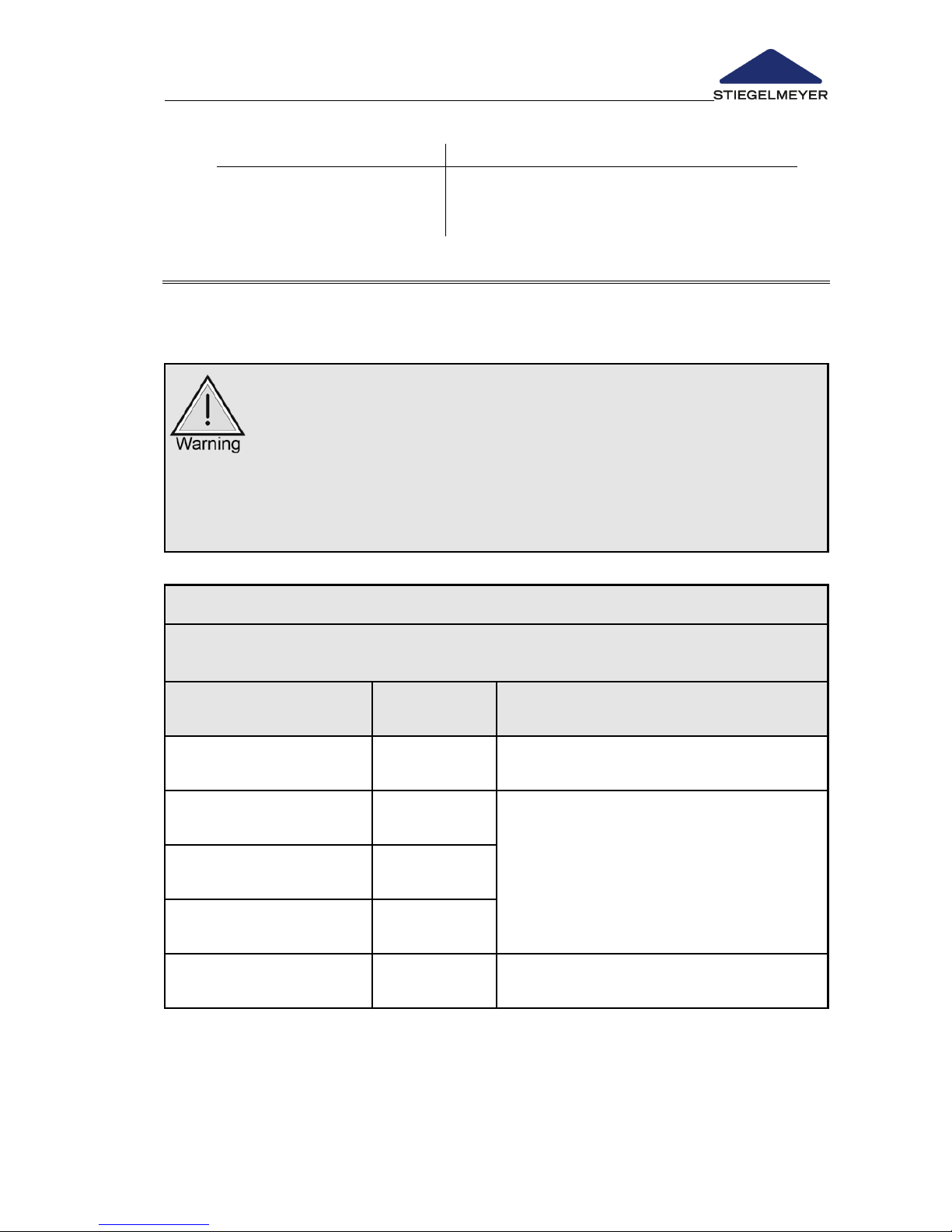
Instruction Manual for Care Bed Libra
Page 85
In operation
Minimum
Maximum
Ambient temperature:
10 °C
40 °C
Relative humidity :
30 %
75 % (not condensed)
Air pressure:
700 hPa
1060 hPa
9.4 TECHNICAL INFORMATION ON ELECTROMAGNETIC COMPATIBILITY (EMC)
To ensure EMC, only use cables and accessories approved by the
manufacturer (see Chapter 9.2).
The use of accessories, sensors or cables other than those approved, with
the exception of sensors and cables sold by the equipment manufacturer
as replacement parts for internal components, can result in an increase in
the transmission level or a reduction in the immunity level of the
equipment.
The equipment may not be used directly next to or on top of other
equipment.
If it is necessary to use the equipment in this way, you must check to ensure
that it functions properly in the required configuration.
Guidelines and Manufacturer’s Declaration – Electromagnetic Emissions –
The bed is intended for use in the electromagnetic environment described below. The
operator or user of the bed should ensure that it is used in such an environment.
Interference emission
measurements
Compliance
Electromagnetic environment - guidelines
HF emissions
to CISPR 11
Group 1
The bed uses HF energy for its internal
functions only.
HF emissions
to CISPR 11
Class B
The bed is intended for use in all types of
establishment including residential and the like
that are directly connected to a public supply
network that also serves buildings that are used
for residential purposes.
Harmonics
according to IEC 61000-3-2
Class D
Voltage fluctuations/
flicker acc. to IEC 61000-3-3
Complies
HF emissions
according to CISPR 14-1
Complies
The bed is not intended for connection to
other technical equipment
Page 88

Instruction Manual for Care Bed Libra
Page 86 -
Guidelines and Manufacturer’s Declaration – Resistance to Electromagnetic Interference –
The BED is intended for use in the electromagnetic environment described below. The
operator or user of the BED should ensure that it is used in such an environment.
Interference
resistance
testing
IEC 60601 - test limit
Compliance
level
Electromagnetic
environment - guidelines
Electrostatic discharge
(ESD)
according to IEC 610004-2
+/- 6 kV contact discharge
+/- 20 kV contact
discharge
Floors should be made of wood
and concrete or be tiled with
ceramic tiles. If the floor is covered
with synthetic flooring material, the
relative air humidity must be at
least 30%. Can be used when
higher ESD levels are present.
+/- 8 kV air discharge
+/-20 kV air discharge
Short, transient electrical
disturbances / bursts
according to IEC 610004-4
+/- 2 kV for network cables
+/- 2 kV for network cables
The quality of the supply voltage
should be equivalent to that of a
typical business or hospital
environment.
+/ 1 kV for input and
output cables
Not applicable
Surges according
to IEC 61000-4-5
+/- 1 kV transversal voltage
+/- 1 kV transversal
voltage
The quality of the supply voltage
should be equivalent to that of a
typical business or hospital
environment.
+/- 2 kV longitudinal voltage
+/- 2 kV longitudinal
voltage
Voltage dips, short
interruptions and
fluctuations in the supply
voltage
according to IEC 610004-11
<5% UT
(>95% dip in UT)
for half a period
<5% UT
(>95% dip in UT)
for half a period
The quality of the supply voltage
should be equivalent to that of a
typical business or hospital
environment.
If the person using the BED
requires that the bed functions
must continue despite any
interruptions in the energy supply,
it is recommended that the BED be
connected to an electricity supply
free from interruptions or a battery.
40% UT
(60% dip in UT)
for 5 periods
40% UT
(60% dip in UT)
for 5 periods
70% UT
(30% dip in UT)
for 25 periods
70% UT
(30% dip in UT)
for 25 periods
<5% UT
(>95% dip in UT)
for 5 s
<5% UT
(>95% dip in UT)
for 5 s
Supply frequency
magnetic fields
(50/60Hz)
according to IEC 610004-8
3 A/m
3 A/m
Network frequency magnetic fields
should be equivalent to those to be
found in a typical business or
hospital environment.
Note:
UT is the AC network voltage before the test level is applied
Page 89
Instruction Manual for Care Bed Libra
Page 87
Guidelines and Manufacturer’s Declaration – Resistance to Electromagnetic Interference –
The bed is intended for use in the electromagnetic environment described below. The operator or user of the BED should
ensure that it is used in such an environment.
Interference
resistance
testing
IEC 60601 - test limit
Compliance
level
Electromagnetic environment - guidelines
Portable and mobile radio devices should not be
used in closer proximity to the BED, including
the cables, than the recommended protection
distance calculated using the equation for the
appropriate transmission frequency.
Recommended protection distance:
Conducted HF
interference
according to
IEC 61000-4-6
3 V
eff
150 kHz to 80 MHz
3 V
eff
150 kHz to 80 MHz
d = 1.17 (P)
1/2
Radiated HF
interference
according to
IEC 61000-4-3
3 V/m
80 MHz to 2500 MHz
3 V/m
for 80 MHz to 2500 MHz
d = 1.17 (P)
1/2
for 80 MHz to 800
MHz
d = 2.33 (P)
1/2
for 800 MHz to 2.5
GHz
with P as the maximum rated power of the
transmitter in watts (W) according to the
manufacturer of the transmitter and d as the
recommended protection distance in metres
(m).b
According to an in-situ test c, the field strength
of stationary radio transmitters should be lower,
for all frequencies, than the compliance level d.
Interference is possible when in the vicinity of
equipment bearing the following sign.
Note 1:
The higher frequency range applies for 80 MHz and 800 MHz.
Note 2:
These guidelines may not be applicable in all circumstances. The propagation of electromagnetic
interference is affected by buildings, objects and people due to absorption and reflection.
c:
The field strength of stationary transmitters, such as base stations for cordless telephones and for public
mobile radio devices, amateur radio stations, and AM and FM radio and television transmitters cannot be
predicted exactly by theoretical means. In order to determine the electromagnetic environment with
regard to the transmitter, a study of the location should be considered. If the field strength measured at
the location where the BED is to be used exceeds the upper compliance limit, the BED should be
observed to check that it functions properly. Should any unusual performance characteristics be
observed, additional measures could be necessary, such as turning the BED or moving it to a different
location.
d:
Across the frequency range of 150 kHz to 80 MHz, the field strength should be less than 3 V/m.
Page 90
Instruction Manual for Care Bed Libra
Page 88 -
Guidelines and Manufacturer’s Declaration – Resistance to Electromagnetic Interference –
Recommended protection distances between portable or mobile HF communication
devices and the BED
The bed is intended for use in an electromagnetic environment in which radiated HF interference is controlled. The
operator or user of the bed can help to avoid electromagnetic interference by keeping a minimum distance between the
bed and any portable or mobile communications devices (transmitters) – depending on the output rating of the
communications device, as described below.
Power
rating of
the
transmitter
[W]
Protection distance (d) dependent on the transmission frequency [m]
150 kHz to 80 MHz
80 MHz to 800 MHz
800 MHz to 2.5 GHz
d = 1.2 (P)
1/2
d = 1.2 (P)
1/2
d = 2.3 (P)
1/2
0.01
0.2
0.2
0.3
0.1
0.4
0.4
0.8
1
1.2
1.2
2.3
10
3.8
3.8
7.3
100
12
12
23
For transmitters whose maximum power rating is not listed in the above table, the distance can be
determined using the equation given in the relevant column, where P is the maximum power rating of the
transmitter in watts (W) as stated by the manufacturer of the transmitter.
Note 1:
The higher frequency range applies for 80 MHz and 800 MHz.
Note 2:
These guidelines may not be applicable in all circumstances. The propagation of electromagnetic
interference is affected by buildings, objects and people due to absorption and reflection.
Page 91
Instruction Manual for Care Bed Libra
Page 89
9.5 CLASSIFICATION
This bed fulfils all the requirements of the 93/42/EEC Medical Device
Directive.
This bed is classified as a Class I medical device (in accordance with the
medical devices act § 13).
For use in the following application groups according to IEC 60601-2-52:
3:
Long-term care in a medical facility in which medical supervision is
required and monitoring is provided if required. A medical electrical
device used in medical procedures can be provided to help maintain
or improve the condition of the PATIENT. (e.g. nursing and care homes,
rehabilitation and geriatric institutions.
4:
Care in the home. A medical electrical device is used to alleviate or
compensate for injuries, disabilities or illnesses.
Active medical device; equipment with type B application component.
UMDNS code:
Bed (electrically adjustable)
10-347
Page 92
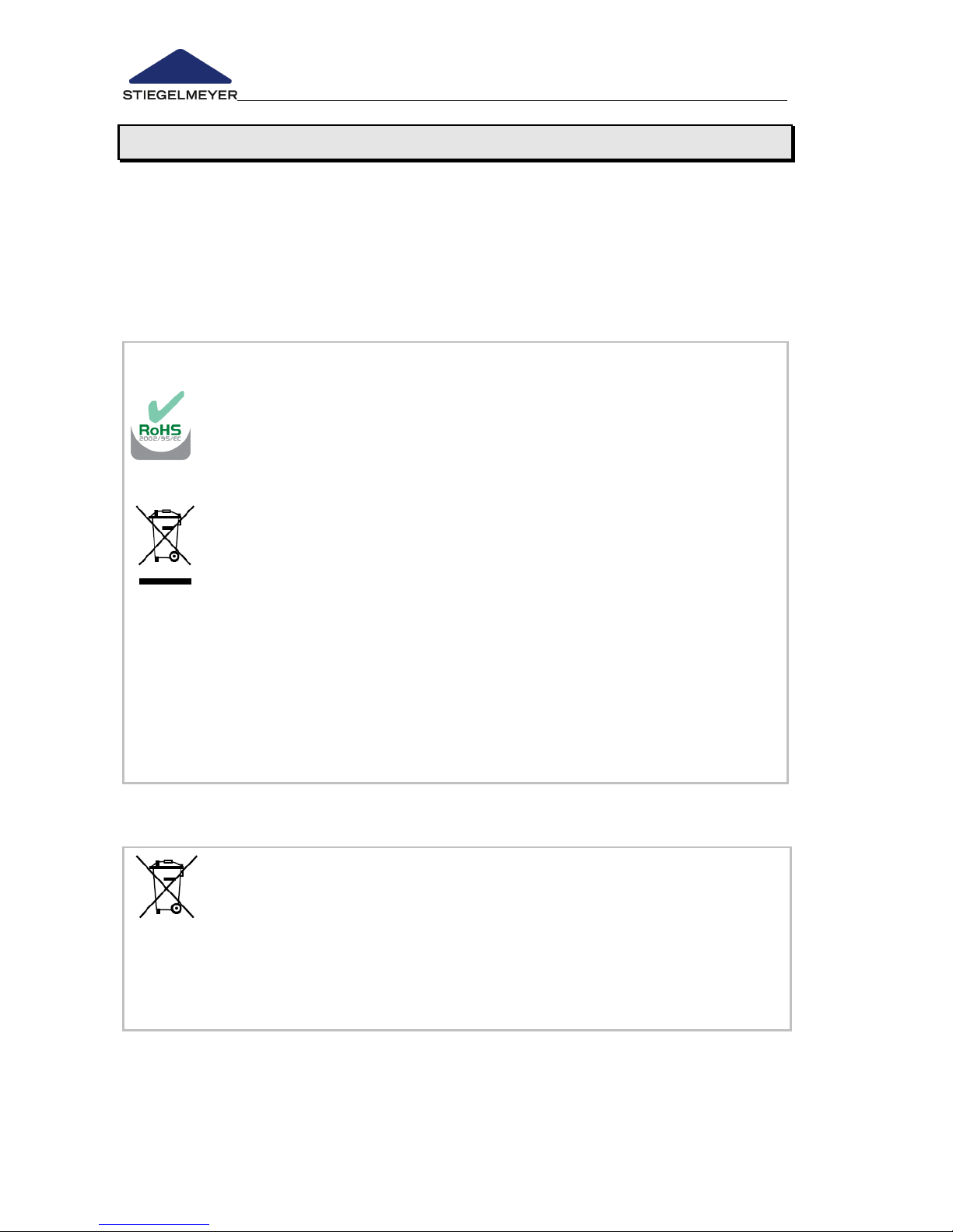
Instruction Manual for Care Bed Libra
Page 90 -
10 Disposal Instructions
The operator must ensure that all components of the bed that are to be
disposed of are not infectious or contaminated.
- If the bed is to be scrapped, the wood, synthetic and metallic parts must
be separated and disposed of properly.
- If you have any queries you can contact your local municipal waste
company or our service department; See Chap. 6.4 for our address.
Disposal of electrical parts
- This bed – since it is electrically adjustable – is classified as a type
(b2b) industrial electrical equipment in accordance with the
WEEE Directive 2012/19/EC (in Germany, law governing
electrical equipment).
- The electrical components used are free from prohibited
hazardous substances in compliance with the RoHS II directive
2011/65/EU.
- Replaced electrical components (drives, control units, handsets,
etc.) must be treated as electric scrap (in accordance with the
WEEE Directive 2012/19/EU) and disposed of accordingly.
- The operator of this bed is legally obliged to send the electrical
components directly to the manufacturer and not to dispose of
them at municipal waste collection points. STIEGELMEYER and its
service and sales partners will take these components back.
- The return of these components is covered by our General Terms
and Conditions.
Disposal of rechargeable batteries
PB
b
- Batteries which are no longer usable and have been removed
must be disposed of properly in accordance with as set out in
directive 2006/66/EC (in Germany, the law governing battery
regulations) and do not belong in household waste.
- If you have any queries you can contact your local municipal
waste company or our service department; you will find our
address in Chapter 6.4.
In other countries outside Germany or the EU, the relevant national
regulations must be complied with.
Page 93
Instruction Manual for Care Bed Libra
Page 91
11 EC – declaration of conformity
EG – Declaration of Conformity
We,
Stiegelmeyer GmbH & CO. KG
Ackerstraße 42
D - 32051 Herford, Germany
hereby declare under sole responsibility as the manufacturer that the
product model named below:
Care bed
models: Soleo; Libra
in the version submitted complies with the regulations of the EC Directive
93/42/EEC Appendix VII for Medical Devices last amended by Directive
2007/47/EC dated 5 September 2007.
It is categorised as a Class I active medical device.
The relevant technical documentation is kept by the manufacturer’s safety
representative. To evaluate the conformity to the Directives, all applicable
parts of the following standards were referred to:
Harmonised standards:
EN 14971: 2013-04
Application of risk management to medical devices
EN 60601-1: 2007-07
Medical Electrical Equipment, Safety
EN 60601-1-2: 2007-12
Electromagnetic Compatibility
DIN EN 60601-1-6: 2010-10
Medical electrical equipment:
Suitability for Intended Use
DIN EN 60601-2-52: 2016-04
Particular requirements for the safety requirements for
the basic safety and essential performance of medical
beds
International standards:
IEC 60601-2-52: 2009-12
+AMD 1: 2015-03
Medical electrical equipment:
Particular requirements for the basic safety and
essential performance of medical beds
IEC 62366:2007
Medical equipment: Usability
Herford, 2016-11-22
Georgios Kampisiulis Kemmler
(Management)
Hans-Peter Löw
(Management)
Page 94

Page 95
Version: 2016-12-05 251937_V2
Published by:
Stiegelmeyer GmbH & Co. KG
Ackerstrasse 42, D- 32051 Herford
Phone: +49 (0) 5221 185-777
Fax: +49 (0) 5221 / 185-219
Email: [email protected]
Internet: www.Stiegelmeyer.com
No part of this manual may be reproduced without
the prior written permission of the publisher.
All rights reserved.
We reserve the right to change technical specifications without prior notice.
 Loading...