

Page 1

Instruction Manual
Hospital Bed
Deka
Date: 2014-10-20 V2_220102
Page 2
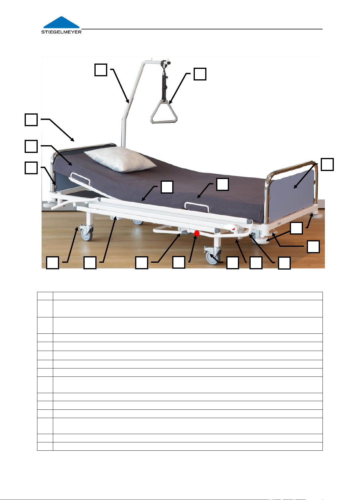
Instruction manual for the hospital bed Deka
1
Castors Ø 125 mm with individual locking, 4 in total
2
Operating lever (on both sides) for adjustment of the backrest (=pull on lever) and
thigh rest (=press lever down),
3
Foot pedal for adjustment of mattress base height: Press pedal down more than
once = to raise mattress base; raise pedal = to lower mattress base
4
Release lever (on both sides) to lock side guards: Pull on lever = to release
5
Universal holders, on both sides
5a
locking knobs for mattress base extension, on both sides
6
Release lever to tilt mattress base: Pull on lever = to release tilting
7
Wall deflection rollers, 4 in total at the outer corners;
8
Headboard/footboard, fully removable with laminate panel, can be removed
individually; (head end/foot end)
9
Grab handle for patient's lifting pole, with strap, height adjustable (accessory)
10
Patient's lifting pole (accessory)
11
Grab handles for backrest / side mattress guides, on both sides
12
Locating sleeve for patient's lifting pole / I.V. stand (2 in total, on left and right at
head end)
13
Side guard, integrated, on both sides
14
Grab handles for lower leg rest / side mattress guides, on both sides
5a
1 8 4
9
6
7
10
3
12
2
11
14 8 1
13
5
5a
1 8 4
9
6
7
10
3
12
2
11
14 8 1
13
5
Deka hospital bed: Operational controls
Illustration with ¾ side guards (Illustration shows optional equipment)
Please note: In this instruction manual, numbers which appear in bold type and square
brackets [ ] refer to features described for the Deka hospital bed.
Page 2
Page 3

Instruction manual for the hospital bed Deka _____________________________________________
1/8
5 4 7 6 3
11
10
Contents
1 FOREWORD .................................................................................................................. 5
2 GENERAL INFORMATION ............................................................................................ 6
2.1 Definition of the Groups of Persons Involved ...................................................... 7
2.2 Safety Information ................................................................................................... 8
2.2.1 Explanation of the safety symbols used ................................................... 8
2.2.2 Safety information for the operator .......................................................... 9
2.2.3 Safety information for the user ................................................................... 9
2.3 Product description .............................................................................................. 11
2.3.1 Designated use .......................................................................................... 11
2.3.2 Special features ......................................................................................... 12
2.3.3 Materials used ............................................................................................ 12
2.3.4 Structural design ........................................................................................ 13
3 PUTTING INTO SERVICE ............................................................................................. 14
3.1 Checklist: Inspection by the user ........................................................................ 15
3.2 Location Requirements ........................................................................................ 15
4 OPERATION ................................................................................................................ 17
4.1 Moving and Braking The Bed .............................................................................. 17
4.2 Manual adjustments ............................................................................................. 18
4.2.1 Safety Information ..................................................................................... 18
4.2.2 Adjusting the backrest .............................................................................. 19
4.2.3 Adjusting the thigh rest ............................................................................. 19
4.2.4 Adjusting the lower leg rest (optional) ................................................... 20
4.2.5 Adjusting the mattress base height ........................................................ 20
4.2.6 Tilting the mattress base............................................................................ 21
4.3 Attachments .......................................................................................................... 22
4.3.1 Location Sleeves for Patient’s Lifting Pole / I.V. Stands ........................ 22
4.3.2 Grab handle (triangular handle) ............................................................ 23
4.3.3 Removing the Headboard/Footboard .................................................. 24
4.3.4 Moulded laminate headboards and footboards ................................ 24
4.3.5 Universal holder .......................................................................................... 25
4.3.6 Bed stripper ................................................................................................. 25
4.3.7 Extending the Mattress Base .................................................................... 27
4.4 Side Guards ............................................................................................................ 29
4.4.1 Safety information for side guards .......................................................... 29
4.4.2 ¾ side guards.............................................................................................. 30
5 CLEANING AND DISINFECTION ................................................................................ 31
6 MAINTENANCE .......................................................................................................... 32
6.1 Servicing ................................................................................................................. 32
6.1.1 Servicing cycle ........................................................................................... 32
6.1.2 Servicing plan ............................................................................................. 33
6.1.3 Regular Safety Checks on Hospital Beds ............................................... 34
6.2 Replacement parts ............................................................................................... 37
6.3 Manufacturer’s address ....................................................................................... 37
Page 3
Page 4

Instruction manual for the hospital bed Deka
7 TROUBLESHOOTING ...................................................................................................38
7.1 Troubleshooting guide ......................................................................................... 38
8 ACCESSORIES .............................................................................................................39
9 TECHNICAL DATA .......................................................................................................40
9.1 Dimensions and Weights ...................................................................................... 40
9.2 Adjustment range ................................................................................................. 40
9.3 Ambient conditions .............................................................................................. 42
9.4 Applied Standards ................................................................................................ 42
9.5 Classification .......................................................................................................... 43
10 DISPOSAL INSTRUCTIONS ...........................................................................................44
11 EC DECLARATION OF CONFORMITY ........................................................................45
Page 4
Page 5

Instruction manual for the hospital bed Deka _____________________________________________
1 Foreword
Dear Customer,
STIEGELMEYER would like to thank you for the confidence you have placed in us in
deciding to purchase this bed.
Each Deka hospital bed has been tested by the manufacturer for electrical safety
and functionality and left our factory in perfect condition.
It is very important that you read this instruction manual.
This applies not only when putting the bed into service for the first time, but also
for the everyday use of the bed. This manual is also a practical reference guide.
Keep the instruction manual at hand at all times.
This instruction manual informs you, as the operator, and your users about all the
functions necessary to ensure ease of operation and the safe handling of this
hospital bed.
We wish you and your users every success in caring for your patients and are
confident that this product enables us to make an important contribution.
Joh. Stiegelmeyer GmbH & Co. Kommanditgesellschaft
Disclaimer
This product is not licensed for use on the North American market. This applies
particularly to the United States of America. The distribution and use of the care
bed in these markets, also via third parties, is forbidden by the manufacturer.
Page 5
Page 6
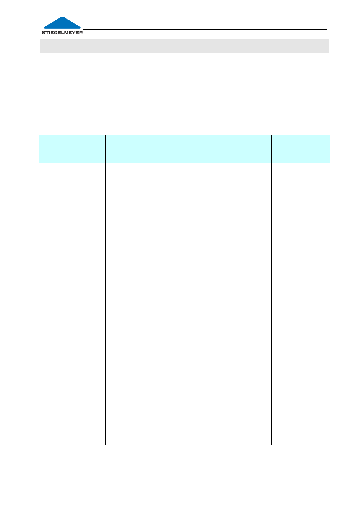
Instruction manual for the hospital bed Deka
Model
Feature
Deka
90cm
Deka
85cm
Side guards
¾- length, integrated, can be folded down
without
o
o
Classic
headboard/footboard: HPL panel - with Ø
32mm metal tubing
Intercontinental: Plastic design,
o
-
Castors
Ø 125mm, castors with individual locking
-
Ø 125mm, castors with central locking, with
steering lock
o
Ø 150mm, castors with central locking, with
steering lock
-
o
Wall deflection
rollers
4 pcs. horizontal working
4 pcs.: 2 pcs. horizontal + 2 pcs. horizontal and
vertical working
o
o
4 pcs. horizontal and vertical working
-
o
Mattress base
insert
Wire mesh (not removable)
Radiolucent backrest; remainder wire mesh
o
-
Hygienic Matress Support Platform
-
o
Lower leg rest
height
adjustment
Adjustment (Rastomat mechanism)
Bed stripper
Integrated under matress base at the foot
end
o
-
Bed extension
Integrated under matress base at the foot
end, 220mm extension range
-
Universal holder
Both sides
Colours
Argentum
o
o
Crystal white
2 General Information
This instruction manual describes several different models of the Deka hospital
bed. The Deka is available in two widths of the mattress base: 85 + 90 cm.
It is possible that certain functions or features are described which are not
incorporated in your particular bed.
In the following text, the Deka hospital bed will be referred to simply as the bed.
Overview of standard features (●) and optional equipment/models (○).
Page 6
Page 7

Instruction manual for the hospital bed Deka _____________________________________________
2.1 DEFINITION OF THE GROUPS OF PERSONS INVOLVED
In this instruction manual, the following groups of persons are defined as:
Operator
An operator (e.g. clinics, hospitals, hospital administrations) is every natural and
legal person with property rights to the Deka hospital bed. The operator is
responsible for the safe operation of this medical product.
Users
Users (e.g. medical specialists, nursing staff, doctors, carers, care workers) are
persons who, based on their training, experience or briefing, are qualified to
operate the bed on their own authority or to carry out works to the bed, or have
been instructed how to handle the bed. Furthermore, they can recognise and
avoid potential dangers and assess the clinical condition of the patient.
Patient
A patient is defined as a person who is infirm, in need of care, or disabled, and
occupies this bed.
It is strongly recommended that the operator or user instructs each new patient in
the bed functions that are important for him/her.
Page 7
Page 8

Instruction manual for the hospital bed Deka
2.2 SAFETY INFORMATION
At the time of leaving the factory, this hospital bed represents state-of-the-art
technology.
Only use the hospital bed if you are absolutely certain that it is in perfect working
order!
The most important objective of the safety information is to prevent personal
injuries. Property damage is also to be avoided.
2.2.1 Explanation of the safety symbols used
In this instruction manual, the following safety symbols are used:
Risk of injury to persons
General danger. There is danger to life and health.
Risk of damage to property
Possible damage to the drive unit, materials or the environment.
Other advice
Useful tip. Eases handling of the hospital bed or improves
understanding.
The safety symbols used are not a substitute for the written safety information.
Therefore read the safety information and follow the instructions precisely!
All persons who work on or with this bed must be familiar with the contents of this
instruction manual and follow all the relevant safety advice.
Page 8
Page 9

Instruction manual for the hospital bed Deka _____________________________________________
2.2.2 Safety information for the operator
In order to ensure the permanently safe operation of this medical product, with
no risk to patients, users or third parties, you must observe your relevant
national obligations (in accordance with the European Directive 93/42/EEC for
Medical Products)!
Using this instruction manual, which must be provided with the bed, ensure that
every user is instructed in the safe operation of the Deka hospital bed before
using it for the first time.
Draw every user’s attention to the possible hazards that can arise if the bed is
improperly used. This applies in particular to the use of electrical drives and
side guards!
Only allow this bed to be used by persons who have been instructed in its safe
operation!
Make sure that substitute staff are also sufficiently well instructed in the safe
operation of the bed!
Check to ensure that the safety instructions are adhered to!
Ensure that users know where this instruction manual is kept, in accordance
with the Operators of Medical Products Ordinance (MPBetreibV) § 9.
If the bed is in long-term use, test the functions and check for any visible
damage (see Chapter 0) after a reasonable period of time.
If any other equipment is attached to the bed, (e.g. compressors for
positioning systems, etc.), ensure that this is securely fastened and is
functioning properly.
Pay particular attention to:
- Safe hook-up of all loose connector cables, tubing, etc.
- Ensure that no multiple socket outlets are located under the bed
- Chapter 2.3.1 Designated use
If in doubt, contact the manufacturers of this equipment or Stiegelmeyer.
2.2.3 Safety information for the user
Ensure that the operator instructs you in the safe operation of this bed.
Read this instruction manual in order to prevent any injury or damage resulting
from incorrect operation.
Check each time before using the hospital bed to ensure that it is in perfect
working order (see Chapter 3.1)!
Ensure that no obstacles such as night tables, floor cable ducts or chairs could
impede adjustments to the bed.
Page 9
Page 10
Instruction manual for the hospital bed Deka
Route the mains cable of additional equipment in such a way
that it cannot be pulled, driven over or be endangered,
damaged or crushed by moving parts when the bed is operated.
Hazards due to electric shock and malfunctions can be avoided
in this way.
Make sure that the mattress base has travelled to its lowest position
before leaving the patient unattended. In this way, you greatly
reduce the risk of the patient injuring himself/herself as a result of
falling when getting in or out of bed.
Always ensure that the castors are braked before leaving the
patient unattended in the bed.
Do not place multiple socket outlets under the bed. This could
cause electrical hazards due to damaged mains cables or
penetrating fluids.
Before carrying out any adjustments, make sure that there are no
limbs or objects in the way, in order to avoid hazards due to
trapping and/or damage to property. This applies particularly
when mattress base sections are adjusted to a lower height.
Observe the safety information found in chapters:
4.4.1 Safety information for side guards
5 Cleaning and Disinfection
- as well as the safety information found in the individual chapters of
this instruction manual!
If other equipment (e.g. compressors for positioning systems, etc.) is attached,
ensure that all items of equipment are fixed securely and function properly.
Pay particular attention to:
- Safe hook-up of all loose connector cables, tubing, etc.
- consult the manufacturer of the equipment in question, or Stiegelmeyer, if
there are any obscurities
If any damage or malfunction is suspected , take the bed out of service:
- indicate clearly that the bed is “Out of Order”
- report this immediately to the operator responsible
Page 10
Page 11

Instruction manual for the hospital bed Deka _____________________________________________
Weight of accessories
(with mattress)
Max. permitted weight
of patient
10kg
215 kg
40 kg
185 kg
2.3 PRODUCT DESCRIPTION
2.3.1 Designated use
- This bed was designed for use in hospitals and comparable medical facilities. It
is used for positioning patients during the diagnosis, treatment, alleviation and
monitoring of illnesses or to compensate for injuries or disabilities. For detailed
use instructions see chapter 9.5.
- This bed may be operated without restrictions and with a permanent
maximum load of 225 kg (= safe operating load, consisting of
occupant and accessories) Symbol:
- The permitted weight of the patient depends on the total weight of
the accessories attached at the same time (e.g. respirators,
infusions,…) Symbols:
The information applicable for your bed is given on a sticker with the above
symbol located on the undercarriage of the bed.
Example:
- This bed is not suitable for patients under 146 cm in height or for small children.
- This bed is designed for re-use. When reusing beds, pay attention to the
necessary requirements:
- Cleaning and Disinfection (see Chapter 5)
- Maintenance / Repeat Inspections (see Chapter 6).
- This bed may be operated only by persons who have received instruction in its
safe operation.
- If the owner of the hospital bed changes, the instruction manual must be
handed over with the bed.
The Deka hospital bed may only be used under the operating conditions
described in this instruction manual.
Its use for any other type of application is deemed to be contrary to the intended
purpose.
Page 11
Page 12

Instruction manual for the hospital bed Deka
2.3.2 Special features
- Fully mechanical version without motors
- Integrated ¾ side guards hinged to fold down when not in use (up to
protection height of 420mm)
- Trendelenburg / anti-Trendelenburg position up to approx. 12 °
- Castors (diameter: 125mm); optional: with central locking; steering lock for
moving in a straight line
- Mattress base in four sections, mattress base area 200 x 90 cm; external
dimensions approx. 103 x 210 cm
- Mattress base height adjustment range from approx. 40 to 77,5 cm
- Adjustment of the backrest from 0° to approx. 70°
- Adjustment of the thigh rest from 0° to approx. 40 °
2.3.3 Materials used
The stretcher is made predominantly of steel sections. Their surface has a
polyester powder coating or a metallic coating made of zinc or chromium.
The mattress base consists of a sturdy steel lattice base or of removable highquality PVC-free plastic inserts.
The undercarriage consists of a welded steel tubular construction.
The headboards and footboard panels consist of moulded laminate boards or
high-quality PVC-free PE plastics.
All surfaces are recognised as being safe for contact with skin.
Page 12
Page 13

Instruction manual for the hospital bed Deka _____________________________________________
2.3.4 Structural design
Mattress base
The mattress base is divided into a backrest, a seat section, a thigh rest and a
lower leg rest. The mattress base height can be adjusted to a horizontal position,
and can be tilted into a Trendelenburg or anti-Trendelenburg position.
All adjustments are performed manually only and are assisted by gas springs.
Undercarriage
The undercarriage is located under the mattress base and its height can be
adjusted with a hydraulic foot pump. Overload protection reduces the risk of
damage to the bed when passing under architectural obstacles.
The Trendelenburg and anti-Trendelenburg positions can be adjusted smoothly
and continuously with the aid of a gas spring.
The bed has four castors that can be centrally locked. Optional: Central castor
locking with a steering lock for easy straight-line travel.
Side guards
The bed is equipped with integrated side guards to protect the patient from
accidentally falling out of bed. Optionally, the side guards can be omitted.
Page 13
Page 14

Instruction manual for the hospital bed Deka
3 Putting into Service
Before putting the bed into service for the first time:
Remove all transport securing devices and packaging film.
Clean and disinfect the hospital bed (see Chapter 5).
Use only authorised accessories (e.g. mattresses, external side guards), to
minimize endangering patients through crushing/ falling out of bed. For further
details see Chapter 4.4.1; 8.
Each time before putting the bed into service, the user must check that:
- the bed has been cleaned and disinfected;
- the castor brakes are applied (see Chapter 4.1);
- no obstacles such as bedside lockers, floor cable ducts or chairs will impede
bed adjustments;
- all adjustment facilities work properly and have been checked (see
Chapter 3.1).
Only after carrying out these checks may the bed be put into service!
Page 14
Page 15
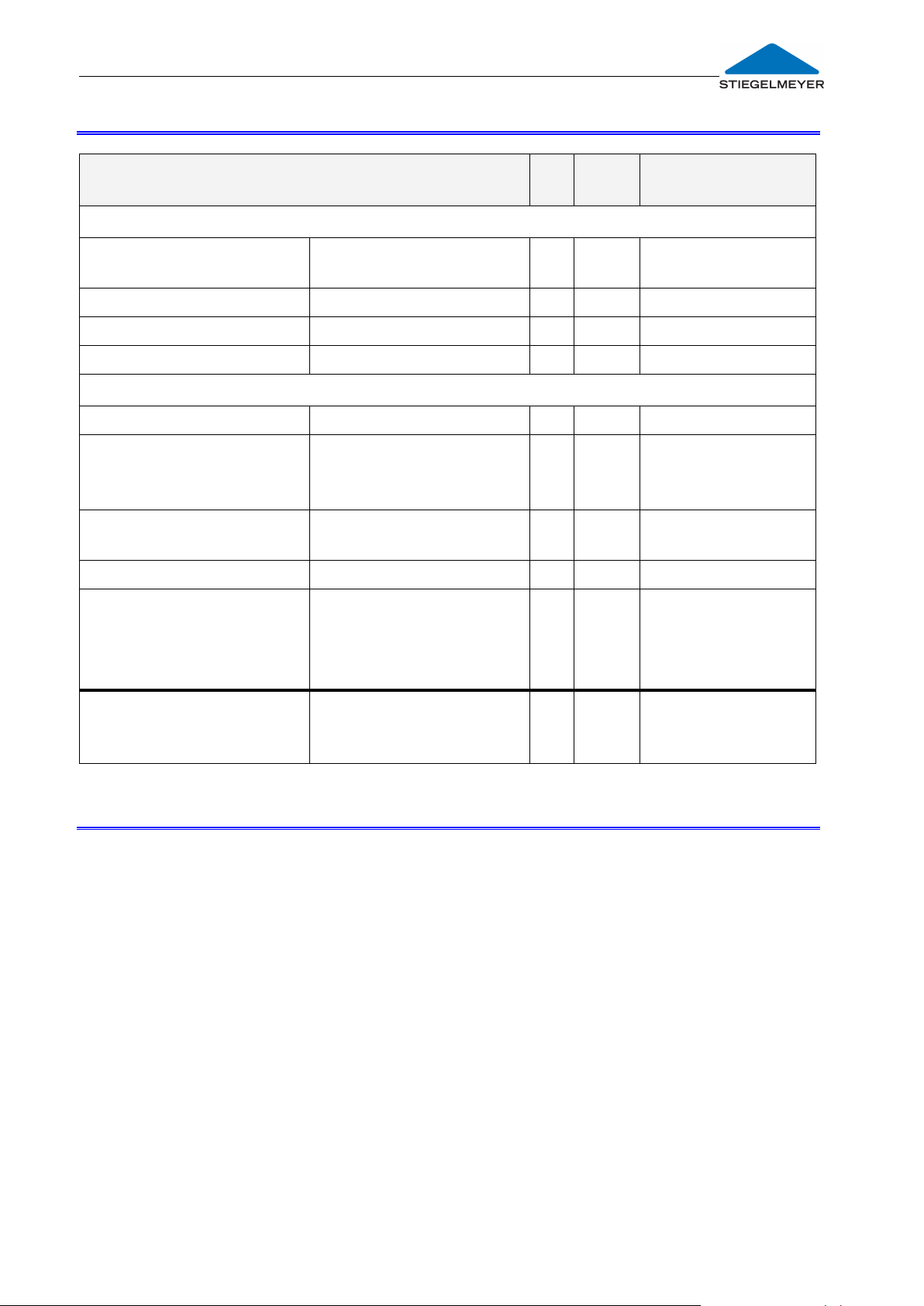
Instruction manual for the hospital bed Deka _____________________________________________
Inspection
ok
Not
ok
Description of
defect
Visual inspection of the mechanical components
Patient’s lifting pole,
location sleeves
Damage, deformation
Grab handle with strap
Damage
Undercarriage
Damage, deformation
Mattress base, covers
Damage, deformation
Performance check of the mechanical components (if installed)
Castors
Locking, moving
Adjusting the backrest
Functional test
according to
instruction manual
Side guards
Functional test,
securely engaged
Lower leg rest
Functional test
Accessories (e.g.
patient’s lifting pole,
grab handle with strap,
bed rails)
Fastenings, damage;
suitability
Inspector’s signature:
Inspection results:
Date:
3.1 CHECKLIST: INSPECTION BY THE USER
3.2 LOCATION REQUIREMENTS
There must be sufficient room available to accommodate the bed’s entire
range of adjustments. Obstacles such as bedside lockers, floor cable ducts,
furniture, or window sills must not impede adjustments.
Before using the bed on parquet flooring, check whether the castors can
leave marks on the parquet varnish. We accept no liability for such wear. The
bed can be used on tiles, carpet, linoleum or laminate flooring without causing
any damage.
If other equipment (e.g. compressors for positioning systems, etc.) is attached,
ensure that all items of equipment are fixed securely and function properly.
Pay special attention here to the safe routing of all loose connector cables,
tubing, etc. If you have any queries or concerns, consult the manufacturer of
the equipment or Stiegelmeyer.
Page 15
Page 16
Instruction manual for the hospital bed Deka
Minimise, as far as possible, the risk of fire due to external influences.
Instruct users on these points:
Use only flame-retardant mattresses and bedding if possible.
Avoid smoking in bed, since the mattress and bedding used may
not be resistant to smokers' accessories.
Only use additional equipment (e.g. electric blankets) and other
electrical devices (e.g. lamps, radios) that are in perfect working
order!
- Ensure that this equipment is used only for the purpose intended.
- Ensure that this equipment is not unintentionally placed on or
under the bedding (danger of overheating)!
Avoid using extension cables or multiple socket bars under the bed
(risk of fire due to penetrating fluids).
Extension cables and/or multiple socket outlets should not be used
at all.
Page 16
Page 17

Instruction manual for the hospital bed Deka _____________________________________________
As a general rule, always apply the brakes when the bed is not
being moved or when a patient is left unattended in the bed.
If individually locking castors are fitted, apply the brakes on each
castor to achieve the maximum brake action and to prevent the
bed from rolling away.
Check to ensure that the bed is properly braked.
Each time before moving the bed, ensure that:
- the cables, tubes or wires of any mounted equipment are
adequately secured and cannot be damaged.
Otherwise the mains cable could sustain damage as a result of
being torn off, crushed or driven over. Such damage could lead to
electrical hazards and malfunctions.
When the bed is moved, ensure that objects hanging in the
universal holder [11] do not cause any damage (e.g. to door
frames).
Risk of crushing! When transporting a patient, ensure that the
patient’s hands and feet do not protrude over the edge of the
bed and that they can not get in the way of the wall deflection
rollers.
Castor brake is released
Castor brake is applied
To apply brake: Press pedal down in
direction a
To release brake: Press pedal down in
direction b
a
b
4 Operation
4.1 MOVING AND BRAKING THE BED
The bed is equipped with four individually locking castors.
Optional: central castor locking at the foot end. A steering lock can be activated
for one castor at the foot end of the bed, which makes it easier to move the bed
in a straight line and to manoeuvre the bed.
With four individually locking castors
Page 17
Page 18

Instruction manual for the hospital bed Deka
When making any adjustments, always ensure that there are no
limbs in the way that could be trapped in the process.
Heavy patients may cause raised backrests/thigh rests to drop very
quickly after actuating the operating lever!
Do not forcibly raise the backrest and thigh rest even higher if these
are already tilted to a high degree, to prevent the risk of trapping
the patient and causing potential congestion of the blood in the
patient's limbs.
When raising the backrest or thigh rest, the flat backrest/thigh rest
may move upwards very quickly after actuating the operating
lever if there is no load resting on it.
For this reason, always grasp the grab handle [11; 14] on the
backrest or thigh rest with one hand before operating the lever
and "control" the adjustment in this way.
Ensure that no obstacles such as night tables, floor cable ducts or
chairs could impede adjustments to the bed.
Ensure that there are no objects on the undercarriage.
Moving without
the steering
lock
Driving with
steering lock:
Lift the foot lever with the top
of your foot.
Driving without
steering lock:
Use your foot to bring the foot
lever to a horizontal position.
Braking:
Push the foot lever down with
your foot.
Braking
Steering lock
Head section
Foot section
Central castor locking at the foot end (optional).
Located to the right and to the left of the
castor pair at the foot end of the bed is a
foot lever which can be used to lock all four
castors.
Steering lock
In order to ensure that the bed moves in a
straight line, the bed is equipped with a
steering lock on one of the castors at the
head end of the bed.
Please note: The castors must first be swivelled
in the direction of travel. With this position of
the pedal, the bed can only be manoeuvred
from the foot end once the steering lock has
engaged. The bed is pushed at this end.
4.2 MANUAL ADJUSTMENTS
4.2.1 Safety Information
Page 18
Page 19

Instruction manual for the hospital bed Deka _____________________________________________
2
11
2
14
4.2.2 Adjusting the backrest
This procedure can be carried out from either of the long sides of the bed.
1. With one hand, grasp the grab handle [11] for the backrest.
2. With the other hand, pull the red operating lever [2], which is located under
the mattress base in the backrest area, upwards and guide the backrest
down to the desired position using the grab handle [11].
The backrest is not held in position until the operating lever [2] is
released.
If there is no load on the backrest and it is steeply raised, it may be
necessary to press it down manually in addition.
4.2.3 Adjusting the thigh rest
This procedure can be carried out from either of the long sides of the bed.
1. With one hand, grasp the grab handle [14] for the thigh rest.
2. With the other hand, press the red operating lever [2], which is located
under the mattress base in the backrest area, downwards and guide the
thigh rest down to the desired position using the grab handle [14].
The thigh rest is not held in position until the operating lever [2] is
released.
If there is no load on the thigh rest and it is steeply raised, it may be
necessary to press it down manually in addition.
Page 19
Page 20
Instruction manual for the hospital bed Deka
- The lower leg rest must lock in place.
Hold the lower leg rest firmly until it is securely locked in place. Do
not allow the lower leg rest to fall.
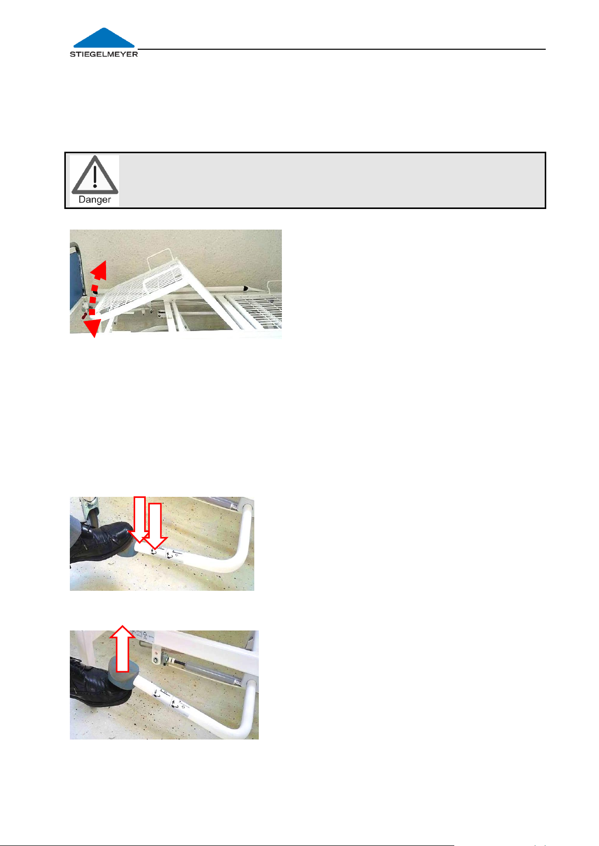
4.2.4 Adjusting the lower leg rest (optional)
The lower leg rest can be raised and lowered manually when the thigh rest is
raised.
In this way it is possible to adjust the bed to an orthopaedic position (stepped
bed) or so that the lower leg rest is declined.
To raise
1. Grasp the lower leg rest frame at the
foot end with both hands.
2. Raise the lower leg rest to the desired
height and release it.
To lower
1. Grasp the lower leg rest frame at the foot end with both hands.
2. Raise the lower leg rest to its full extent.
3. Lower the lower leg rest slowly.
- The lower leg rest automatically moves to a horizontal position when the thigh
rest is lowered.
4.2.5 Adjusting the mattress base height
Adjustment is made using a hydraulic foot pump.
To raise
Press the pedal down repeatedly until the
desired mattress base height is reached.
To lower
Raise the pedal with your foot.
The mattress base is lowered.
Release the pedal when the desired mattress
base height is reached.
Page 20
Page 21

Instruction manual for the hospital bed Deka _____________________________________________
Risk of injury!
- After actuating the release lever, a heavy patient may cause the
mattress base to crash down. Before actuating the release lever,
take hold of the outer edge of the mattress base and control the
tilting in this way.
6
4.2.6 Tilting the mattress base
- Grasp the foot end of the bed with one
hand.
- Pull the release lever [6] away from the
foot end with the other hand.
- Now, depending upon the desired
tilting direction, either lift the foot end of
the mattress base up or press it down.
- Release the lever when the required mattress base position has been reached.
The mattress base will be held in this position.
- The mattress base can be tilted into the Trendelenburg and anti-
Trendelenburg positions.
- If the mattress base is at a very high setting, it is automatically
lowered if necessary when tilting.
- If the mattress base is at a very low setting, then it may be necessary
to first raise the mattress base before tilting into the antiTrendelenburg position.
A spirit-level is mounted on the inside of the foot section for
easy horizontal adjustment.
The mattress base is in a horizontal position when the air
bubble is located between the two marks.
Page 21
Page 22
Instruction manual for the hospital bed Deka
The maximum loading capacity at the front end of the patient's lifting
pole is 75 kg.
The patient's lifting pole is not suitable for rehabilitation exercises.
Pay attention to door clearances when moving beds with patient’s
lifting poles or I.V. stands attached.
A grab handle (accessory) is normally attached to the patient’s lifting
pole.
See the description provided on the following page.
12
Recess
Slewing
range
4.3 ATTACHMENTS
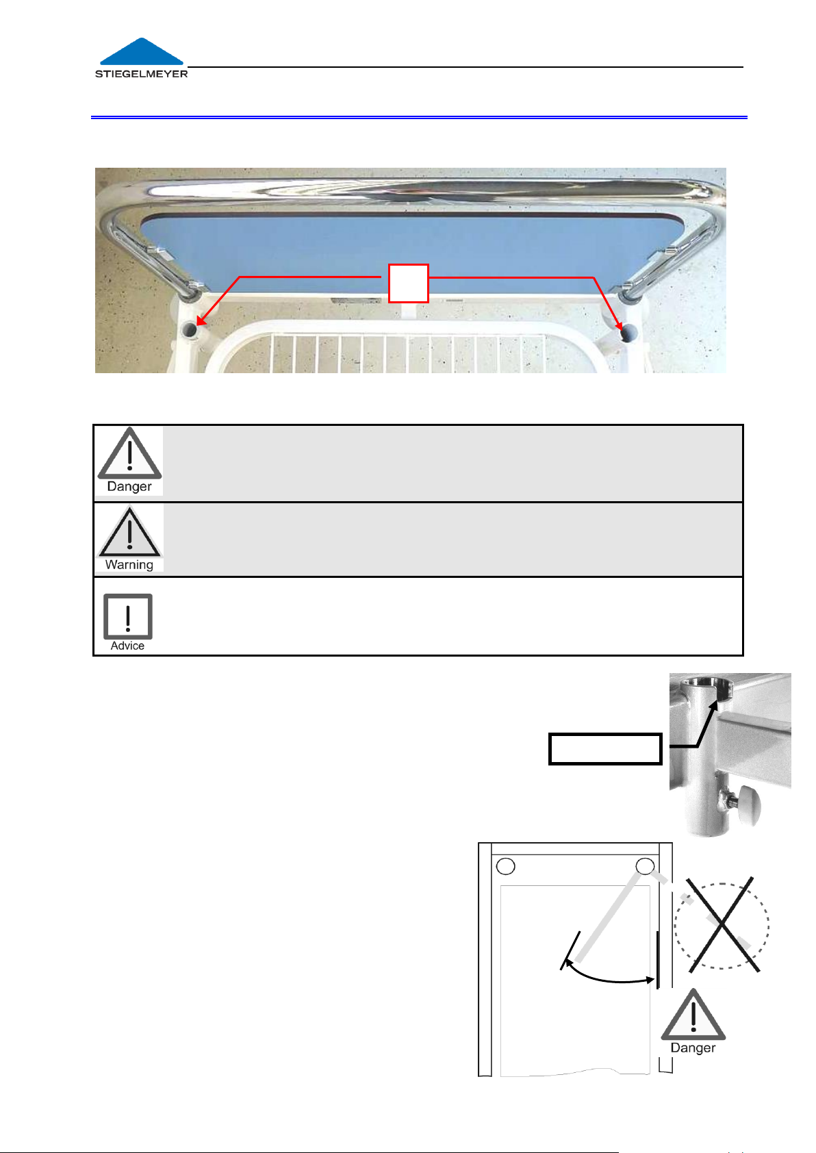
4.3.1 Location Sleeves for Patient’s Lifting Pole / I.V. Stands
On the inside of the headboard, there are two sleeves [12] for fixing a patient’s
lifting pole or I.V./drip stands (accessories).
Inserting the patient's lifting pole
Insert the long, straight end of the patient's lifting pole into a sleeve [12].
The metal pin on the patient's lifting pole
must be located in the notch of the sleeve.
This restricts the slewing range of the
patient's lifting pole (see illustration below).
The pole is now facing the centre of the
bed and can swing to the side as far as the
restriction allows.
Removing
Pull the patient’s lifting pole up and out of
the sleeve.
Slewing range of the patient’s lifting pole
If the pole swings outside the bed area and
is loaded there, there is a danger that the
bed will tip when weight is applied to the
pole.
Therefore the metal pin must always sit in
the sleeve recess!
Page 22
Page 23

Instruction manual for the hospital bed Deka _____________________________________________
Check the grab handle and strap regularly for damage (see Chapters
3.1 and 6.1.2).
Damaged grab handles or straps must be replaced immediately.
min. 3 cm
Buckle
4.3.2 Grab handle (triangular handle)
A grab handle can be attached to the patient’s lifting pole (accessory, see
Chapter 8).
The patient can use this grab handle to sit up and readjust his/her position.
Service life:
We recommend that the triangular grab handle is replaced at least
every 5 years!
Push the fixed loop of the grab handle over
the first bolt on the patient's lifting pole.
Check the secure position of the grab
handle by strongly pulling it downwards.
Please note: The maximum loading
capacity at the front end of the patient's
lifting pole is 75 kg.
- The height of the grab handle can be
adjusted using the strap.
Make sure that the strap is correctly
threaded through the buckle.
Make sure that the end of the strap projects
at least 3 cm from the buckle.
Page 23
Page 24

Instruction manual for the hospital bed Deka
The openings on the locating brackets must always face outwards
away from the bed.
Otherwise there is a risk that the patient could lift the laminate
panel out himself/herself. The laminate panel would then fall to
the floor.
Locating
bracket
4.3.3 Removing the Headboard/Footboard
The headboard and footboard [1] are both identical and can be removed if
required without using tools to provide easier access to the patient.
Stand behind the headboard/footboard.
Using both hands, grasp the top corners of the headboard/footboard and
pull it up and out as evenly as possible without tilting it.
Dismantle in reverse order.
Removing Inserting
4.3.4 Moulded laminate headboards and footboards
The headboard and footboard contain moulded laminate panels. These panels
can be removed.
The headboard and footboard can be used for reanimation purposes.
Removing
Lift the laminate panels upwards and pull away towards the bed.
Inserting
Insert the moulded laminate panel from
the inside of the bed.
Make sure that all four locating brackets
of the laminate panel slot onto the
corresponding bolts.
Page 24
Page 25

Instruction manual for the hospital bed Deka _____________________________________________
Ensure that attached objects do not cause damage (e.g. to
door frames) when moving the bed.
Ensure that patients or third parties are not exposed to risks (risk
of being trapped).
The maximum load-bearing capacity of the bed stripper is 15 kg.
Do not lean on the bed stripper!
Do not stand or sit on the bed stripper!
5
Gallery rail
4.3.5 Universal holder
One universal holder [5] is attached at the foot end of each of the long sides of
the bed. This universal holder can be used for hanging accessories, urine bottle
holders, drainage bags, universal brackets, etc.
4.3.6 Bed stripper
There are two versions available. Please refer to the corresponding one of your
bed.
A: The bed stripper can be pulled out from under
the mattress base at the foot end of the bed.
- To prevent the bedding from falling, the bed
stripper has a gallery rail. This rail can be folded
up when necessary.
Sliding in
Before sliding the bed stripper
back under the mattress base, fold
the gallery rail back down!
Page 25
Page 26

Instruction manual for the hospital bed Deka
1 2 3
Lift up the foot board with
each hand at the outer
top edges.
Fold the board smoothly
outwards. Do not remove
your hands – the boar
might fall.
Remove your hands when
the board has reached
the working position.
B) The foot board can be fold outwards as a bed
stripper
Folding in
Perform in opposite sequence (3 – 2 – 1).
Page 26
Page 27

Instruction manual for the hospital bed Deka _____________________________________________
click
click
H B F
Similar to illustration
Similar to illustration
¼
5a
1 2 3
4.3.7 Extending the Mattress Base
The brakes of the bed should be applied.
Loosen the two black locking knobs [5a] under the
mattress base on the left and the right sides of the
bed at the foot end:
o Pull the locking knobs down and give the knobs
a quarter turn in a clockwise or anti-clockwise
direction.
o The knob will now lock in place in this “open
position”.
o Leave the locking knobs in this position for the time
being.
Hold the left and right outer edges of the footboard
with both hands half way up the footboard [1].
Now pull the bed extension out towards you as far as
possible.
Ensure that the bed extension remains in this end position by turning both
locking knobs to the “secure position”.
o To do so, proceed in the same way as when you loosened the knobs.
o Finally, jiggle the footboard until the safety pins on the locking knobs
engage properly. A click is heard when the safety pins are engaged.
o Check that the mattress base is firmly locked in place by pushing the
footboard backwards and forwards.
Inserting the mattress foam insert (accessory)
Place the support base (accessory) from above
into the centre of the space for the extension.
The foam insert restraint (B) on the long side must
face the foot end (F).
The two fixing clips (H) on the metal bars that
extend into the space for the extension must
click into place.
Page 27
Page 28

Instruction manual for the hospital bed Deka
Ensure that the resulting gap is always filled with the corresponding
foam insert.
This effectively prevents the risk that the patient could become
trapped in the bed extension area.
Similar to illustration
Place the mattress foam insert
(accessory) from above into
the centre of the support
base.
You will find a list of
accessories in Chapter 8
showing the different versions
of mattress foam insert that
are available.
Restoring the mattress base to its normal size
Remove the mattress foam insert:
1. The fixing clips for the support base are now visible.
Press them outwards in turn by hand on both sides
of the bed
and
2. Lift the support base out of the space for the
extension.
To shorten the mattress base, follow the steps for extending the base in the
reverse order.
Page 28
Page 29

Instruction manual for the hospital bed Deka _____________________________________________
Only use technically perfect, undamaged side guards which
securely engage!
Before using the side guards, assess and take into consideration the
clinical condition and particular physical build of the patient:
o For example, if the patient is extremely confused or very restless,
avoid using side guards as much as possible and make use of
alternative safety measures such as posey belts, restraint sheets,
etc.
o In the case of particularly small, slightly built patients it may be
necessary to use an additional form of protection to reduce the
size of the side rail gaps. In these cases, use protective covers
(accessories), posey belts, etc. This is the only way to ensure
effective protection and reduce the risk of the patient getting
trapped or slipping through the gaps.
Only use suitable mattresses (not too soft) to DIN 13014 with a
volume weight of at least 40 kg/m³ and dimensions complying with
the specifications in the instruction manual for the bed (in the
Chapter "Accessories"), to prevent endangering patients through
trapping or suffocation.
The maximum mattress height depends on the model and the
position of the side guards used. An effective side guard height of at
least 22 cm above the unloaded mattress must be guaranteed.
If elevated patient positioning systems are used (for prevention or
therapy), e.g. mattresses to prevent bedsores, an effective side
guard height of at least 22 mm above the non-occupied mattress
must be guaranteed.
If this dimension is not adhered to, according to the latest safety
standard for beds IEC60601-2-52, the operator must take
additional/alternative measures on his own responsibility and
according to his assessment of the risks in view of the clinical
condition of the patient, such as:
providing additional safety systems for the patient,
arranging for the patient to be monitored regularly,
issuing internal instructions for the users.
Type of side guards
Max. mattress
height (mm)
Integrated, 3/4
200
4.4 SIDE GUARDS
4.4.1 Safety information for side guards
Side guards provide suitable protection for patients against falling out of bed.
They are not intended as a device to prevent the patient from intentionally
leaving the bed.
Observe the maximum admissible mattress height.
Page 29
Page 30

Instruction manual for the hospital bed Deka
click
4
click
4
4.4.2 ¾ side guards
Raising the side guards
1. Grasp the top rail of the side guard
with one hand.
2. Raise the rail by pulling and
pivoting it towards the head end
of the bed until it is fully raised. The
entire side guard is raised in the
process.
3. The side guard must audibly click
into place and the red release
button [4] must not protrude!
4. Check that the side guard is
securely fixed in place by pushing
and pulling the top rail from one
end to the other!
5. Repeat the procedure for the other side
guards.
Lowering the side guards
1. Grasp the top rail of the side guard with
one hand at the foot end.
2. Pull the red release button [4] out completely
with two fingers of the other hand, and
3. lower the other rail slowly with a pivoting motion
towards the foot end of the bed - do not let it
drop!
4. Repeat the procedure for the other side guard.
Page 30
Page 31

Instruction manual for the hospital bed Deka _____________________________________________
Manufacturer
Designation
Concentration according to
manufacturer
Antiseptica
Biguacid-S
0.5% solution
B.Braun
Meliseptol rapid
Meliseptol
Working solution 50ml/ m
2
Bode Chemie
Bacillol AF
Working solution 50ml/ m2
Ecolab
Incidin Plus
0.5% solution
Fresenius-Kabi
Ultrasol-F
0.5% solution
Lysoform
Amocid
1.5% solution
Schülke
Buraton 10 F
5% solution
Do not use scouring agents, abrasive cleaning agents or scouring
pads.
These substances can damage the surfaces.
Do not use organic solvents such as halogenated/aromatic
hydrocarbons and ketones.
Do not use acidic cleaning solvents.
Please follow the manufacturer’s dosage advice to avoid
damaging the plastic and metal surfaces!
Ensure that after cleaning/ disinfection no liquid residues remain on
the metallic parts of the bed (avoid drops on the edges).
Otherwise corrosion can not be excluded in these areas in the long
term.
Despite the excellent mechanical resistance, scratches, markings,
etc., which permeate the entire coating should be resealed using
a suitable repair medium to prevent the penetration of moisture.
Please refer to Chapter 6.1.2 for special varnishes which are
suitable for this purpose.
5 Cleaning and Disinfection
For disinfection by wiping, most cleaning and disinfection agents usually used
in hospitals or care facilities, such as cold and hot water, detergents, alkaline
solutions and alcohols, can be used.
These agents may not contain any substances that could change the surface
structure or the adhesive properties of the plastic materials.
The following cleaning agents were successfully tested and approved by us:
Please consult the appropriate manufacturer before using any other agents.
Only alternative agents with an equivalent composition may be used, to
prevent any damage to the bed as a result.
Page 31
Page 32

Instruction manual for the hospital bed Deka
Damage, defects and wear resulting from improper operation and
after long-term use can not be ruled out.
These deficiencies can cause hazards if they are not recognised and
corrected immediately.
Before carrying out any maintenance work, please bear in mind
that in order to make any adjustments the bed must be connected
to the mains supply. Make sure to disconnect the mains plug from
the mains socket when the service works are finished. Also switch
off all the drives using the control panel or blocking box.
If any damage or malfunction is suspected, take the bed out of
service at once until it has been repaired or the damaged
component has been replaced!
6 Maintenance
Legal principles
In accordance with
EC Medical Product Directive 93/42 EEC
and the relevant national laws/regulations which result from this (e.g. in Germany)
German Ordinance for Operators of Medical Products § 4 (Maintenance)
operators of hospital beds are obliged to preserve the safe operating condition of
medical products throughout their entire service life. This also includes regularly
carrying out expert maintenance as well as safety checks.
In other countries outside Germany or the EU, the relevant national regulations
must be complied with.
6.1 SERVICING
6.1.1 Servicing cycle
As a guideline, we recommend a yearly inspection by our qualified service
engineers.
Please consult our service department; see page 37 for the address.
Page 32
Page 33

Instruction manual for the hospital bed Deka _____________________________________________
Measure
Material/tool
Check that all screw connections and/or metal
safety caps are firmly positioned;
tighten/replace if necessary.
Suitable tools.
Do not re-use safety caps, to
ensure a perfect hold
If necessary, clean and slightly oil the
connecting bolts on the headboard and
footboard as well as the corresponding sleeves
on the vertical bed frame tubing.
Resin-free and acid-free
grease.
If necessary, clean and lightly spray the pivot
and friction bearings.
Resin-free and acid-free oil
spray (e.g. lubricant A).
Check the adjustment and routing of the
Bowden cable for the tilting of the backrest.
Must move smoothly and easily. No sharp
bends or kinks
Safe routing of Bowden cable.
Touch up any damage in the coating.
Special-purpose paint
(mechanically stable
anticorrosive protection) in a
suitable colour
Colour
Designation
Stiegelmeyer item no.
silver
Varnish (500g tin)
203803
Accelerator (100g tin)
203805
white
Varnish (500g tin)
203804
Designation
Stiegelmeyer item no.
A
Weicon: Allround Lubricant AL-W
190507 (400mL aerosol spray)
193231 (1000 mL aerosol spray)
6.1.2 Servicing plan
Special varnishes recommended
Key to recommended lubricants
In order to optimise the fault-free operation of the beds and thus minimise
downtime, we recommend that servicing of the bed should include additional
special preventative measures.
A practical guide on preventative replacement of components that may be
affected can be requested under
Stiegelmeyer Assist GmbH & Co. KG
Page 33
Page 34

Instruction manual for the hospital bed Deka
If damage or malfunctions are found, the bed must be taken out of
operation immediately until it has been repaired or the defective
components have been replaced!
A repeat inspection must be carried out in accordance with the test
sheet to determine whether the damage or malfunction has been
rectified.
The bed may only be put into operation again once this
precondition has been met.
Regular Safety Checks on Hospital Beds
Inspection cycle
As a guideline, we recommend a yearly inspection by our qualified service
engineers.
In accordance with EN 62353 (VDE 0751) (Association of German Electrical
Engineers – Regulation 0751), the inspection results may only be evaluated and
documented by experts with the corresponding knowledge, training and
experience. Furthermore, these experts must demonstrate proven knowledge of
the beds to be inspected as well as knowledge of the relevant requirements
(Medical Products Directive 93/42 EEC) as well as the respective national
laws/regulations which result from this.
Observe this order for the inspection according to EN 62353 (VDE 0751):
1) Visual inspection
2) Performance inspection
The protocol template for inspections based on the EN 52353 (VDE 0751) standard
is found on the following pages.
Page 34
Page 35

Instruction manual for the hospital bed Deka _____________________________________________
Customer / med. facility / practice:
Address:
Carried out: Repeat inspection Inspection prior to initial operation(reference value)
Inspection following repairs/servicing
Equipment type: Hospital bed Care
bed
Protection class: I II not electric
Bed type: Deka
Inventory number:
Location:
Serial number:
Manufacturer: Stiegelmeyer GmbH & Co. KG
User-specific parts: None
Testing equipment used (type/inventory no.): 1.
MP-RL 93/42 Classification: Class I
2.
I. Visual inspection
WHAT TO CHECK What to check for
ok
Not
ok
Description of
defect
Visual inspection of the mechanical components (if applicable)
Stickers and type plates
Present, legible
Patient’s lifting pole, location
sleeves
Grab handle with strap
Damage, deformation; grab
handle not more than 5 year old?
(see date)
Undercarriage
Damage or deformation
Castors
Damage
Mattress base
Damage
Welded seams
Welded seams split?
Gas springs, dampers,
hydraulics
Damage, sealing
Side guards
Damage, cracks, deformation
Connecting elements
(screws, bolts, nuts, safety caps)
Fixed position, completeness
Wearing parts, joints
Damage, severe wear
II. Performance check
WHAT TO CHECK What to check for
ok
Not
ok
Description of
defect
Performance inspection of the mechanical components (if applicable)
Joints and pivots
Smooth operation
Gas springs: (backrest; leg rests,
tilting of mattress base)
Sufficient supporting force;
reliable blocking; smooth
adjustment
Height adjustment using
hydraulic pump /foot pedal
Sufficient lifting force
Lower leg rest (Rastomat)
Snapped into place properly
Grab handle with strap
Securely fixed under 75 kg load
Castors
Effective brakes, securely engaged
brake
Side guards
Safe locking, unlocking
Accessories (e.g. patient’s
lifting pole, grab handle)
Fixing, damage, suitability
X
Inspection Report following an inspection of electromedical equipment according to
DIN EN 62353 (VDE 0751-1): 2008-08 - Page 1 of 2
Page 35
Page 36

Instruction manual for the hospital bed Deka
Overall inspection result:
Defects/remarks:
No safety or functional defects were detected
No direct risk, the defects detected can be rectified quickly
Appliance must be taken out of circulation until the defects have been rectified!
Appliance does not conform to requirements – modification/replacement of
components/decommissioning recommended.
Test approval sticker applied: yes no
Next inspection date:
Documents that form part of this inspection report:
Checked
Date:
Name:
Signature:
Test approval
sticker
applied:
Date:
Name:
Signature:
Address/stamp of responsible company.
Inspection Report following an inspection of electromedical equipment
according to DIN EN 62353 (VDE 0751-1): 2008-08 - Page 2 of 2
Page 36
Page 37
Instruction manual for the hospital bed Deka _____________________________________________
Model
Bed and model
Type
Item number
No
Order number
Bar code
Consecutive serial
number
Deka
123456
123456
Example of a
6.2 REPLACEMENT PARTS
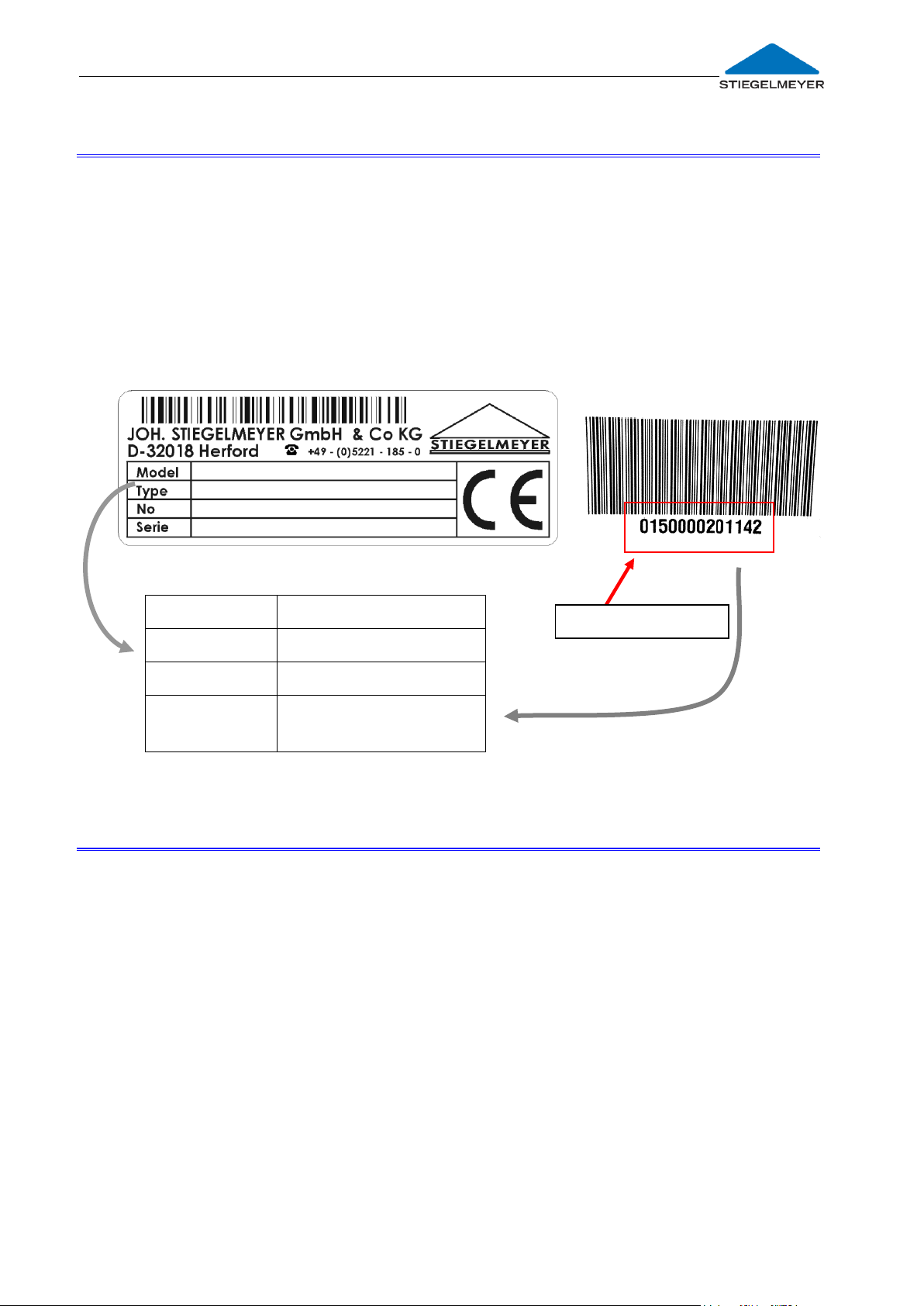
In order to maintain operational safety and the right to claim under warranty, only
original Stiegelmeyer replacement parts may be used!
For quick and easy ordering of replacement parts we require the following
information from you:
Customer number
and the following details, which you will find on the type plate and on a separate
bar code located on the cross tubing at the head end of the bed.
6.3 MANUFACTURER’S ADDRESS
To order replacement parts, or make customer service requests or other queries,
please contact our service department:
Joh. Stiegelmeyer GmbH & Co. KG
Ackerstrasse 42, 32051 Herford
POB 28 54, 32018 Herford
Telephone: +49 (0) 5221 185-0
Fax, general: +49 (0) 5221 185-219
Fax, customer service requests +49 (0) 5221 / 185-443
Email: [email protected]
Page 37
Page 38

Instruction manual for the hospital bed Deka
PROBLEM
Possible causes
Solution
Manual adjustment
of backrest is not
possible
Rod that connects release
lever and gas spring is bent
or has become detached
Readjust at the release
lever or secure
Manual adjustment
of thigh rest is not
possible
Rod connecting release
lever and gas spring is bent
or has become detached
Readjust at the release
lever or secure
Manual tilting of
mattress base is not
possible
Bowden cable too long /
has become detached
Bowden cable jammed /
kinked
Adjust length of
Bowden cable
Rectify the cause; fix
securely; replace if
necessary
Manual tilting of
mattress base cannot
be blocked
Bowden cable too short
Bowden cable jammed /
does not reset itself
Adjust length of
Bowden cable
Rectify the cause; fix
securely; replace if
necessary
7 Troubleshooting
7.1 TROUBLESHOOTING GUIDE
The following table is a guide for rectifying faults:
Page 38
Page 39
Instruction manual for the hospital bed Deka _____________________________________________
Efficient and safe operation combined with maximum protection of
patients can only be guaranteed if original Stiegelmeyer accessories
are used which are designed for the relevant model of bed!
Designation
Item number
Patient's lifting pole W-06, round tube, chrome-plated, with
triangular grab handle
Patient's lifting pole W-06, as above but white
219773
219623
I.V. stand K-06, straight
219627
Urine bottle holder U-14
116266
Standard mattress (polyether cold foam): LxWxH:
200 x 90 x 12 cm (density 45 kg/m3)
219894
Double extension frame W-07
219629
Universal holder
116263
Document holder RG-01
180201
8 Accessories
A wide range of accessories is available for the Deka hospital bed, and we are
continually extending this range.
Accessory lists can be obtained from us quoting the bed model.
Here is a small sample of the accessories available:
Page 39
Page 40

Instruction manual for the hospital bed Deka
Dimensions
Deka (85cm)
Deka (90cm)
Weights
External
dimensions:
2135 x 970 mm
2095 x 1025 mm
Empty weight:
(without
accessories)
130 kg
Mattress base:
(mattress
dimensions)
850 x 2000 mm
2000 x 900 mm
Safe working
load:
225kg
Mattress base
sections:
(back/seat/thigh/
lower leg)
710/143/ 414 / 615 mm
Max. patient
weight:
185 - 210
(depending on the
weight of
accessories
attached)
Castors:
Ø 125 mm
Ø 150 mm
(Option)
Ø 125 mm
Max. lifting
capacity:
approx. 250 kg
Protection height
of side guards:
420mm (above the mattress base)
Height adjustment
range:
410 to 790 mm
(Castors Ø 125 mm)
435 to 790 mm
(Castors Ø 150 mm)
Raised outstretched leg
position
0° to 30°
Backrest:
0° to 70°
Tilting range of mattress
base to Trendelenburg/antiTrendelenburg position
0° to 16°
Deka (85 cm)
0° to 12°
Deka (90 cm)
Thigh rest:
0° to 40°
9 Technical Data
9.1 DIMENSIONS AND WEIGHTS
9.2 ADJUSTMENT RANGE
All figures given are approximate values.
Operating noise: max. 40 dB(A)
Page 40
Page 41

Instruction manual for the hospital bed Deka _____________________________________________
Symbols:
Meaning
Details in
Chapter
Attention! Pay attention to the instruction manual
2
Mark of conformity in accordance with the Medical
Product Directive 93/42, EEC Appendix VII
11
Safe working load (= max. permissible weight of patient,
mattress and all accessories attached)
9.1
Max. weight of patient (= max. permissible weight of
patient; this is dependent on the total weight of all the
accessories attached to the bed and is always less than the safe
working load)
2.3.1 ;
9.1
Only use mattresses that are approved by the
manufacturer with the dimensions specified.
4.4.1: 8
Operating instructions for operating lever for manual
adjustment of the backrest/thigh rest
4.2.2
4.2.3
Operating instructions for operating lever for manual tilting
of the mattress base
4.2.6
Operating instructions for hydraulic foot pump
4.2.5
Symbols used:
Page 41
Page 42

Instruction manual for the hospital bed Deka
Minimum
Maximum
Storage temperature:
+ 5° C
+ 50° C
Relative humidity :
50 %
70 %
Minimum
Maximum
Ambient temperature:
+ 10° C
+ 40° C
Relative humidity :
20 %
90 %
(not condensed)
Air pressure:
700 hPa
1060 hPa
9.3 AMBIENT CONDITIONS
The following ambient conditions must be maintained:
In storage:
In operation:
9.4 APPLIED STANDARDS
EC Guideline 93/ 42ᅠ Medical Products Directive
DIN EN ISO 14971:2009-10 Risk management for medical devices
DIN EN 60601-1-6:2010 Medical electrical equipment:
Fitness for use
DIN EN IEC 60601-2-52: 2010 Particular requirements for the safety and essential
performance of medical beds
Page 42
Page 43

Instruction manual for the hospital bed Deka _____________________________________________
1
Intensive care in a hospital, whereby 24-hour medical supervision and
constant monitoring are required. The provision of a life support
system/device for use in medical procedures is very important for the
support of the patient’s vital functions.
2
Acute care in a hospital or in other medical establishments, in which
medical supervision and monitoring are required. A medical electrical
(ME) device for use in medical procedures is often provided to help
maintain or improve the condition of the patient.
3
Long-term care in a medical facility in which medical supervision is
required and monitoring is provided if required. A medical electrical
device used in medical procedures can be provided to help maintain or
improve the condition of the patient.
N.B.: This includes rehabilitation and geriatric institutions.
5
Outpatient care facility which is provided in a hospital or other medical
establishment under medical supervision. A medical electric device is
provided for the needs of persons with an illness, injury or handicap for
the purpose of treatment, diagnosis or monitoring.
Bed (mechanically adjustable)
10-357
9.5 CLASSIFICATION
This hospital bed fulfils all the requirements of the 93/42/EEC Medical Products
Directive.
This bed is classified as a class I medical product (in accordance with
Appendix IX of the Medical Products Directive 93/42/EEC).
For use in the following application groups according to IEC 60601-2-52:
UMDNS Code:
Page 43
Page 44

Instruction manual for the hospital bed Deka
The release mechanism must not be activated if gas springs are
removed. These devices are under pressure.
Careless release could cause injury!
- Gas springs must first be depressurised according to the
manufacturer’s instructions before disposal. This information
can be obtained upon request from the gas spring
manufacturer (see type plate).
10 Disposal instructions
- The operator must ensure that all components of the bed that are to be
disposed of are not infectious or contaminated.
- If the bed is to be scrapped, the synthetic and metallic parts are to be
separated and disposed of properly.
- If you have any queries you can contact your local municipal waste
company or our service department; you will find our address on page 37
Disposal of gas springs/hydraulic units
Any gas springs and hydraulic units are primarily constructed from metal and
plastic and can be recycled.
Before disposing of the gas springs, it is important to depressurize
them and drain off the oil.
Please note in this connection:
Page 44
Page 45
Instruction manual for the hospital bed Deka _____________________________________________
EC declaration of conformity
We,
Joh. Stiegelmeyer GmbH & CO. Kommanditgesellschaft
Ackerstraße 42
D - 32051 Herford,
hereby declare under sole responsibility as the manufacturer that the product model
named below:
Hospital Bed
Deka
in the version submitted complies with the regulations of the EC Directive 93/42/EEC
for Medical Products, last amended by Directive 2007/47/EC dated 5 September
2007.
It is categorised as a Class 1 active medical product.
The relevant technical documentation is kept by the manufacturer’s safety
representative.
To evaluate the conformity to the Directives, all applicable parts of the following
standards were referred to:
Applied harmonised standards:
EN 14971:2009-10 Risk Analysis for Medical Products
DIN EN 60601-1-6:2010 Medical electrical equipment:
Suitability for intended use
DIN EN 60601-2-52: 2010-12 Particular requirements for the safety and essential
performance of medical beds
National standards/ specifications:
Additional safety requirements for care beds of the supreme German state authority
dated 22 May 2001
International standards:
IEC 60601-2-52:2009-12 Medical electrical equipment: Particular
requirements for the basic safety and essential
performance of medical beds
Herford, 2011-10-11
Holz Wiedemann
(Management) (Management)
11 EC declaration of conformity
Page 45
Page 46

Instruction manual for the hospital bed Deka
Notes:
Page 46
Page 47

Instruction manual for the hospital bed Deka _____________________________________________
Notes:
Page 47
Page 48
Instruction manual for the hospital bed Deka
Published by:
Joh. Stiegelmeyer GmbH & Co. Kommanditgesellschaft
Ackerstrasse 42, 32051 Herford, Germany
Telephone: 05221/185-0 • Fax: 05221/185-252
Email: [email protected]
www.stiegelmeyer.com
No part of this manual may be reproduced without the prior written permission of
the publisher. All rights reserved.
Subject to technical changes without notice!
Deca_v2_220102_GB Edition: 2014-10-20
Page 48
 Loading...