

Page 1
OPERATION AND INSTALLAT ION
Air | water heat pump
» WPL 15 AS
» WPL 15 ACS
» WPL 20 A
» WPL 20 AC
» WPL 25 A
» WPL 25 AS
» WPL 25 AC
» WPL 25 ACS
Page 2

CONTENTS
SPECIAL INFORMATION
OPERATION
1. General information �����������������������������������������3
1.1 Safety instructions ����������������������������������������������� 3
1.2 Other symbols in this documentation ����������������������� 4
1.3 Units of measurement ������������������������������������������ 4
1.4 Standardised output data �������������������������������������� 4
2. Safety ���������������������������������������������������������� 4
2.1 Intended use ������������������������������������������������������ 4
2.2 Safety instructions ����������������������������������������������� 4
3. Appliance description ���������������������������������������5
3.1 Properties ��������������������������������������������������������� 5
3.2 Function ����������������������������������������������������������� 5
4. Settings �������������������������������������������������������5
5. Maintenance and care ���������������������������������������6
6. Troubleshooting ����������������������������������������������6
INSTALLATION
7. Safety ���������������������������������������������������������� 7
7.1 General safety instructions ������������������������������������ 7
7.2 Instructions, standards and regulations �������������������� 7
8. Appliance description ���������������������������������������7
8.1 Standard delivery ������������������������������������������������ 7
8.2 Accessories �������������������������������������������������������� 7
9. Preparations �������������������������������������������������� 7
9.1 Sound emissions ������������������������������������������������� 7
9.2 Minimum clearances �������������������������������������������� 8
9.3 Preparation of the installation location ��������������������� 8
9.4 Siting ��������������������������������������������������������������� 8
9.5 Installing supply lines and supply cables ������������������ 10
9.6 WPM heat pump manager ������������������������������������ 10
9.7 Buffer cylinder �������������������������������������������������� 10
9.8 Preparing the electrical installation ������������������������ 11
10. Installation �������������������������������������������������� 11
10.1 Handling ���������������������������������������������������������� 11
10.2 Siting �������������������������������������������������������������� 11
10.3 Heating water connection ������������������������������������� 11
10.4 Flow and return connection ���������������������������������� 12
10.5 Fitting the push-fit connector �������������������������������� 12
10.6 Oxygen diffusion ������������������������������������������������ 13
10.7 Filling the heating system ������������������������������������ 13
10.8 Minimum flow rate ��������������������������������������������� 13
10.9 Setting the flow rate on the heating side ������������������ 13
10.10 Condensate drain ����������������������������������������������� 15
10.11 External second heat generator �����������������������������15
10.12 Safety temperature controller for underfloor heating
system STB-FB �������������������������������������������������� 15
11. Power supply ����������������������������������������������� 15
11.1 Power connection WPL15AS| WPL15ACS ��������������� 17
11.2 Power connection WPL20A| WPL20AC| WPL25A|
WPL25AC �������������������������������������������������������� 17
11.3 Power connection WPL25AS| WPL25ACS ��������������� 18
11.4 Electrical connection of supplementary heating facility 18
12. Commissioning ��������������������������������������������� 20
12.1 Checks before commissioning�������������������������������� 20
12.2 Using the appliance with an external second heat
generator ��������������������������������������������������������� 20
12.3 Settings ����������������������������������������������������������� 20
12.4 Operation and control ����������������������������������������� 21
12.5 Decommissioning ����������������������������������������������� 21
13. Maintenance ������������������������������������������������ 21
14. Troubleshooting �������������������������������������������� 22
14.1 Checking the IWS DIP switch settings ���������������������� 22
14.2 Light emitting diodes (LEDs) ����������������������������������23
14.3 Reset button ����������������������������������������������������� 24
14.4 Resetting the high limit safety cut-out ��������������������� 24
14.5 Fan noise ��������������������������������������������������������� 24
15. Specification ������������������������������������������������ 26
15.1 Dimensions and connections ��������������������������������� 26
15.2 Wiring diagram for WPL15AS| WPL15ACS|
WPL25AS| WPL25ACS (single-phase) ������������������� 28
15.3 Wiring diagram for WPL20A| WPL20AC| WPL25A|
WPL25AC (3-phase) �������������������������������������������30
15.4 Output diagrams WPL15AS| WPL15ACS ���������������� 32
15.5 Output diagrams WPL20A| WPL20AC ��������������������34
15.6 Output diagrams WPL25A| WPL25AC| WPL25AS|
WPL25ACS ������������������������������������������������������ 36
15.7 Data table �������������������������������������������������������� 38
GUARANTEE
ENVIRONMENT AND RECYCLING
2 |WPL A | WPL AC | WPL AS | WPL ACS www.stiebel-eltron.com
Page 3
SPECIAL INFORMATION | OPERATION
General information
SPECIAL INFORMATION
- The appliance may be used by children aged 8
and up and persons with reduced physical, sensory or mental capabilities or a lack of experience
and know-how provided that they are supervised
or they have been instructed on how to use the
appliance safely and have understood the resulting risks. Children must never play with the appliance. Children must never clean the appliance
or perform user maintenance unless they are
supervised.
- Use a permanent connection to the power supply.
The appliance must be able to be separated from
the power supply by an isolator that disconnects
all poles with at least 3mm contact separation.
- Maintain the minimum clearances to ensure trouble-free operation of the appliance and facilitate
maintenance work.
- Maintenance work, such as checking the electrical safety, must only be carried out by a qualified
contractor.
- We recommend an annual inspection (to establish
the system’s current condition), and maintenance
by a qualified contractor if required (to return the
system to the desired condition).
OPERATION
1. General information
The chapters “Special Information” and “Operation” are intended
for both the user and qualified contractors.
The chapter "Installation" is intended for qualified contractors.
Note
Read these instructions carefully before using the appliance and retain them for future reference.
Pass on the instructions to a new user if required.
1.1 Safety instructions
1.1.1 Structure of safety instructions
KEYWORD Type of risk
!
Here, possible consequences are listed that may result
from failure to observe the safety instructions.
Steps to prevent the risk are listed.
1.1.2 Symbols, type of risk
Symbol Type of risk
!
Injury
Electrocution
- Following isolation from the mains supply, parts
of the appliance may remain live for up to 2 minutes since the capacitors still have to discharge
into the inverter.
- Never interrupt the power supply, even outside
the heating period. The system’s active frost protection is not guaranteed if the power supply is
interrupted.
- If the heat pump and frost protection are completely switched off, drain the system on the
water side.
1.1.3 Keywords
KEYWORD Meaning
DANGER Failure to observe this information will result in serious
injury or death.
WARNING Failure to observe this information may result in serious
injury or death.
CAUTION Failure to observe this information may result in non-seri-
ous or minor injury.
www.stiebel-eltron.com WPL A | WPL AC | WPL AS | WPL ACS | 3
Page 4

OPERATION
Safety
1.2 Other symbols in this documentation
Note
General information is identified by the symbol shown
on the left.
Read these texts carefully.
Symbol Meaning
!
This symbol indicates that you have to do something. The ac-
tion you need to take is described step by step.
Material losses
(appliance and consequential losses, environmental pollution)
Appliance disposal
1.3 Units of measurement
Note
All measurements are given in mm unless stated otherwise.
1.4 Standardised output data
Explanations to determine and interpret the specified standardised
output data.
1.4.1 EN 14511
The output data specifically mentioned in text, diagrams and
technical datasheets has been calculated according to the test
conditions of the standard shown in the heading of this section.
However, there is a deviation from this norm in the output data for
air/water inverter heat pumps at source temperatures of > -7°C
as this concerns partial load values. The associated percentage
weighting in the partial load range can be found in EN14825 and
EHPA quality label regulations.
Generally, the test conditions stated above will not fully meet the
conditions found at the installation site of the system user.
Depending on the chosen test method and the extent to which
this method deviates from the test conditions defined in the first
paragraph of this section, any deviations can have a considerable
impact.
Further factors that have an influence on the test values are the
measuring equipment, the system configuration, the age of the
system and the flow rates.
A confirmation of the specified output data can only be obtained
if the test conducted for this purpose is also performed in accordance with the test conditions defined in the first paragraph
of this section.
2. Safety
2.1 Intended use
Observe the application limits listed in chapter "Specification /
Data table".
This appliance is intended for domestic use. It can be used safely
by untrained persons. The appliance can also be used in a non-domestic environment, e.g. in a small business, as long as it is used
in the same way.
Any other use beyond that described shall be deemed inappropriate. Observation of these instructions and of instructions for any
accessories used is also part of the correct use of this appliance.
2.2 Safety instructions
Observe the following safety instructions and regulations.
- Only qualified contractors should carry out the electrical
work and installation of this appliance.
- The qualified contractor is responsible for adherence to all
currently applicable instructions during installation and
commissioning.
- Operate the appliance only when fully installed and with all
safety equipment fitted.
- Protect the appliance from dust and dirt ingress during
building work.
WARNING Injury
!
The appliance may be used by children aged 8 and up and
persons with reduced physical, sensory or mental capabilities or a lack of experience and know-how provided
that they are supervised or they have been instructed
on how to use the appliance safely and have understood
the resulting risks. Children must never play with the
appliance. Children must never clean the appliance or
perform user maintenance unless they are supervised.
4 |WPL A | WPL AC | WPL AS | WPL ACS www.stiebel-eltron.com
Page 5
OPERATION
Appliance description
3. Appliance description
3.1 Properties
The appliance is a heating heat pump for outdoor installation that
operates as an air | water heat pump. Heat is extracted from the
outdoor air at a low temperature level, and is then transferred to
the heating water at a higher temperature. The heating water can
be heated up to a flow temperature of 65°C.
The appliance is equipped with an electric emergency/booster
heater (DHC). If the dual mode point can no longer be maintained
in mono mode operation, the electric emergency/booster heater is activated to safeguard heating operation and the provision
of high DHW temperatures. In such cases, the electric emergency/booster heater is activated in mono energetic operation as a
booster heater.
This appliance has further operational characteristics:
- Suitable for underfloor and radiator heating.
- Preferred for low temperature heating systems.
- Extracts heat from the outdoor air even at –20 °C outside
temperature.
- Corrosion-protected, external casing made from hot-dipped
galvanised sheet steel plus stove-enamelled finish.
- Comprises all components and safety equipment required for
operation.
- Filled with non-combustible safety refrigerant.
Note
For centralised control of the heating system you will
need heat pump manager WPM.
3.2 Function
3.2.1 Heating
Heat is extracted from the outdoor air via the heat exchanger
(evaporator) on the air side. The evaporated refrigerant is compressed by a compressor. Electrical energy is necessary for this
process. At this point, the refrigerant is at a higher temperature
level. A further heat exchanger (condenser) transfers the heat to
the heating circuit. During this process, the refrigerant expands,
and the cycle restarts from the beginning.
At air temperatures below approx. +7 °C, the humidity in the air
condenses as hoarfrost on the evaporator fins. Any hoarfrost is
automatically defrosted. Water created by this process collects in
the defrost pan and is drained off via a hose.
The heat pump automatically reverts to heating mode at the end
of the defrost cycle.
Material losses
!
In dual mode operation, the return water of the second
heat generator can flow through the heat pump. Please
note that the return temperature must be no higher than
60°C.
3.2.2 Cooling
Material losses
!
The heat pump is not suitable for continuous, year-round
cooling.
Observe the application limits (see chapter “Specifi-
cation / Data table”).
Rooms are cooled by reversing the heat pump circuit. Heat is
extracted from the heating water and the evaporator transfers
this heat to the outdoor air.
Area cooling requires the installation of the FEK remote control
unit in a reference room to capture the relative humidity and the
room temperature as part of monitoring the dew point.
Heat pump application limit
The heat pump is switched off if the outside temperature falls
below the selected lower application limit for cooling (parameter
LIMITCOOLING).
4. Settings
The system is operated exclusively by the WPM heat pump manager.
Please observe the heat pump manager operating and instal-
lation instructions.
Material losses
!
In the defrost cycle, the fan is switched off and the heat
pump circuit is reversed. The heat required for defrosting
is drawn from the buffer cylinder. For operation without a
buffer cylinder, observe chapter „Operation / Menu structure / Menu SETTINGS/ STANDARD SETTING / BUFFER
OPERATION“ in the operating and installation instructions
of the WPM. Otherwise the heating water freezes under
unfavourable conditions.
www.stiebel-eltron.com WPL A | WPL AC | WPL AS | WPL ACS | 5
Page 6
OPERATION
Maintenance and care
5. Maintenance and care
Material losses
!
Maintenance work, such as checking the electrical safety,
must only be carried out by a qualified contractor.
A damp cloth is sufficient for cleaning all plastic and sheet metal
parts. Never use abrasive or corrosive cleaning agents.
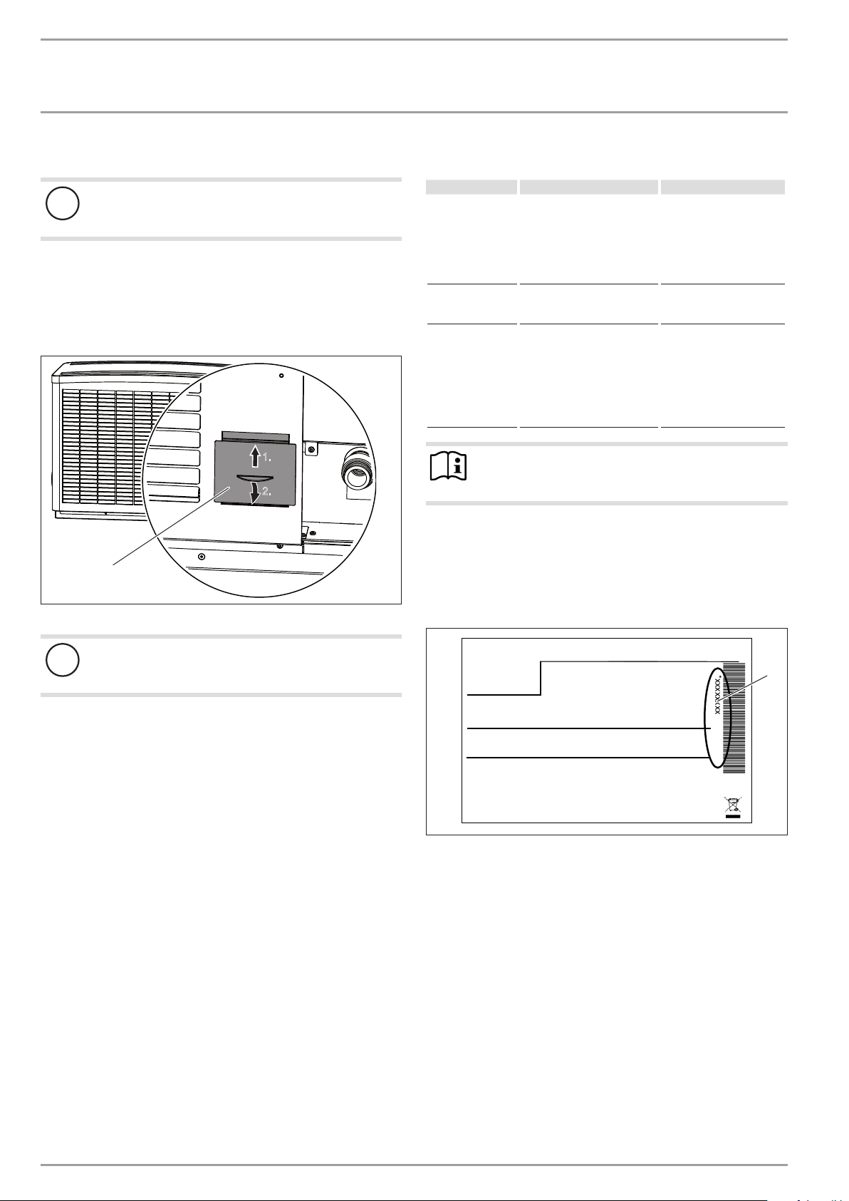
Regularly check the condensate drain (visual inspection). Remove
contamination and blockages immediately (see chapter "Installation/ Condensate drain").
1.
2.
1
1 Inspection port
6. Troubleshooting
Fault Cause Remedy
There is no hot
water or the heating system stays
cold.
The external unit
leaks water.
This can cause the
humidity in the
outdoor air to accumulate as dew or
frost on the cooled
heat pump casing
Note
Even when the condensate is draining away correctly,
expect water to drip from the appliance onto the floor.
If you cannot remedy the fault, notify your qualified contractor.
To facilitate and speed up your enquiry, please provide the serial
number from the type plate. The type plate is located at the front
top, on the right or left hand side of the casing.
D0000037831
Sample type plate
No power at the appliance.
The condensate drain may be
blocked.
The heat pump is drawing
heat from the outdoor air to
heat the building. This can
cause the humidity in the
outdoor air to accumulate as
dew or frost on the cooled
heat pump casing. This is not
a defect.
Check the fuses/MCBs in
your fuse box/distribution
panel. Replace the fuses/
reset the MCBs if required.
Notify your qualified contractor if the fuses/MCBs
blow/trip again.
Clean the condensate drain
as described in „Maintenance and care“.
Material losses
!
Keep the air discharge and intake apertures free from
snow and leaves.
We recommend an annual inspection (to establish the current condition of the system), and maintenance by a qualified contractor if
required (to return the system to its original condition).
Protect the appliance from dust and dirt ingress during building
work.
Montageanweisung beachten! Dichtheit geprüft!
1 Number on the type plate
Made in Germany
*xxxxxxxxxxxxxxxxxx*
1
26�03�01�1736
6 |WPL A | WPL AC | WPL AS | WPL ACS www.stiebel-eltron.com
Page 7
INSTALLATION
Safety
INSTALLATION
7. Safety
Only a qualified contractor should carry out installation, commissioning, maintenance and repair of the appliance.
7.1 General safety instructions
We guarantee trouble-free function and operational reliability only
if original accessories and spare parts intended for the appliance
are used.
7.2 Instructions, standards and regulations
Note
Observe all applicable national and regional regulations
and instructions.
8. Appliance description
The appliance offers frost protection for the connection lines. The
integral frost protection circuit starts the circulation pump in the
heat pump circuit automatically at a condenser temperature of
8 °C, and thereby ensures circulation in all water-carrying sections. If the temperature inside the buffer cylinder drops, the heat
pump starts automatically no later than when the temperature
falls below +5°C.
8.1 Standard delivery
The following are delivered with the appliance:
- Wiring diagram
9. Preparations
The appliance is designed for siting in front of a wall. Observe the
minimum clearances. If the appliance is installed in an open space
or on a roof, protect the air intake side. Do this by erecting a wall
to shield it against the wind.
9.1 Sound emissions
The appliance is louder on the air intake and air discharge sides
than on the two enclosed sides. Observe the following information
when selecting the installation location.
Note
For details regarding the sound power level, see chapter
"Specification / Data table".
- Lawn areas and shrubs help reduce the spread of noise.
- Sound propagation can also be reduced by installing closely
spaced palisade fencing around the appliance.
Ensure that the air intake direction is the same as the main
wind direction.
Air should not be blown out against the wind.
Never direct the air intake or discharge towards noise-sensi-
tive rooms of the house, e.g. bedrooms.
Avoid installation on large, echoing floor areas, e.g. tiled
floors.
Avoid installation between reflective building walls. Reflect-
ing building walls can increase the sound level.
Maintain the minimum clearances to ensure trouble-free op-
eration of the appliance and facilitate maintenance work.
8.2 Accessories
8.2.1 Required accessories
- Heat pump manager in wall mounting enclosure, WPM
8.2.2 Further accessories
- Remote control for heating systems FEK
- Remote control for heating systems FE7
- Ribbon heater HZB-1
- Ribbon heater HZB-2
- Safety temperature controller for underfloor heating system
STB-FB
- T-support SK-WPL
- Wall mounting support WK 2
- Mounting bracket MK 1
- Connection set AS-WP 1
- Connection set AS-WP 2
www.stiebel-eltron.com WPL A | WPL AC | WPL AS | WPL ACS | 7
Page 8
INSTALLATION
750
Preparations
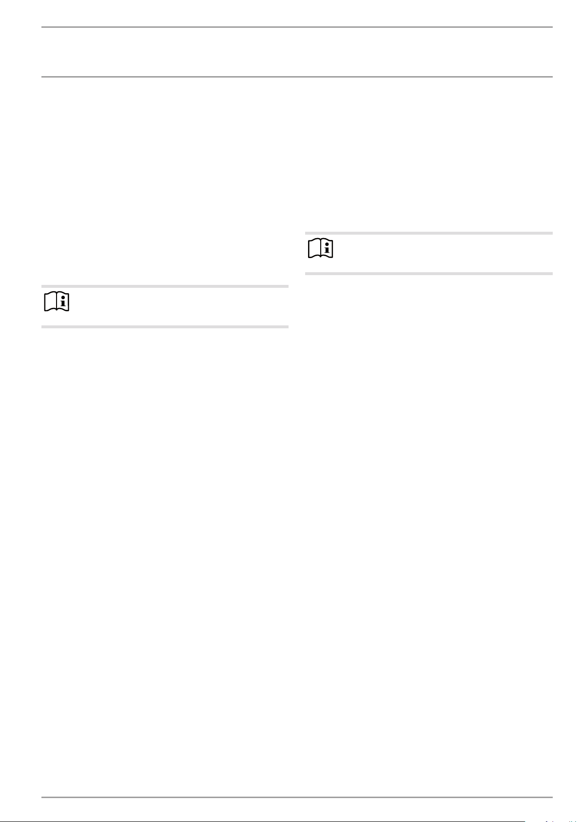
9.2 Minimum clearances
≥1000
≥800
≥300
≥500
9.4 Siting
Note
If the condensate drain hose is not laid with frost protection or is exposed to severe weather conditions, installation of a ribbon heater is recommended both with the
plinth and the wall mounting support.
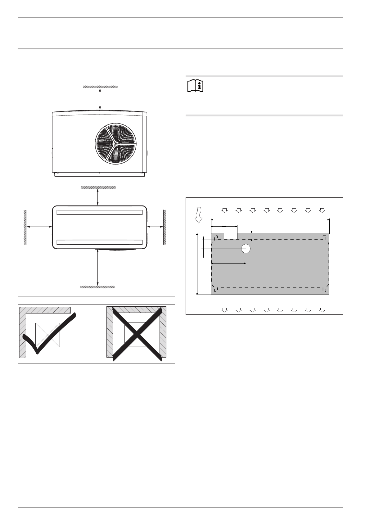
9.4.1 Example: Pipe routing above ground or mounting
bracket MK 1
- The substrate must be horizontal, level, solid and permanent.
Ensure the entire appliance frame is in full contact with the
substrate. Uneven substrates can increase noise emissions.
If the supply lines are run downwards through the ground, they
must be laid in a recess (space) in the foundation.
WPL15AS| WPL15ACS
1
3
200
140
4
1300
75
≥2000
Do not install the appliance in a recess. Two sides of the ap-
pliance must remain exposed.
9.3 Preparation of the installation location
Observe chapter “Sound emissions”.
Ensure that the appliance is accessible from all sides.
5
100
D000002829991�00�00�0036
410
2
1 Air intake
2 Air discharge
3 Main wind direction
4 Supply line recess
5 Condensate drain recess (minimum diameter 70mm)
Ensure that the foundations offer the necessary recess.
D0000034133
8 |WPL A | WPL AC | WPL AS | WPL ACS www.stiebel-eltron.com
Page 9
INSTALLATION
750
6
1
Preparations
WPL20A| WPL20AC| WPL25A| WPL25AS| WPL25AC|
WPL25ACS
1
3
200
140
4
5
100
410
1 Air intake
2 Air discharge
3 Main wind direction
4 Supply line recess
5 Condensate drain recess (minimum diameter 70mm)
Ensure that the foundations offer the necessary recess.
1500
75
2
Hook two brackets respectively into the lateral slots on the
front and back. Ensure you are using the correct brackets for
the left and right hand slots respectively.
Position the brackets so that the groove on the bracket is
D0000028298
hooked into the appliance.
Secure the appliance to the foundations using the brackets
and suitable rawl plugs and screws.
Note
Do not use the screws with which the appliance was
secured to the transport pallet.
D0000064201
Example: Laying pipes above ground
Example: Mounting bracket MK 1 (only WPL15AS |
WPL15ACS)
Note
The mounting bracket cannot be used in combination
with the connection sets (AS-WP1 and AS-WP2).
4
5
1
2
A
7
3
8
A 100
B 300
C Depth of frost line
1 Heating flow
5
2
1
AB
3
C
4
D0000028297
2 Heating return
3 Condensate drain
4 Condensate drain pipe
5 Foundation
6 Gravel bed
A Depth of frost line
1 Heating flow
6
D0000060818
2 Heating return
Note
The transport brackets can be used to secure the appliance to the foundations.
3 Conduit for supply lines
4 Foundation
5 Mounting support
6 Gravel bed
7 Drainage pipe
8 Condensate drain
www.stiebel-eltron.com WPL A | WPL AC | WPL AS | WPL ACS | 9
Page 10
INSTALLATION
Preparations
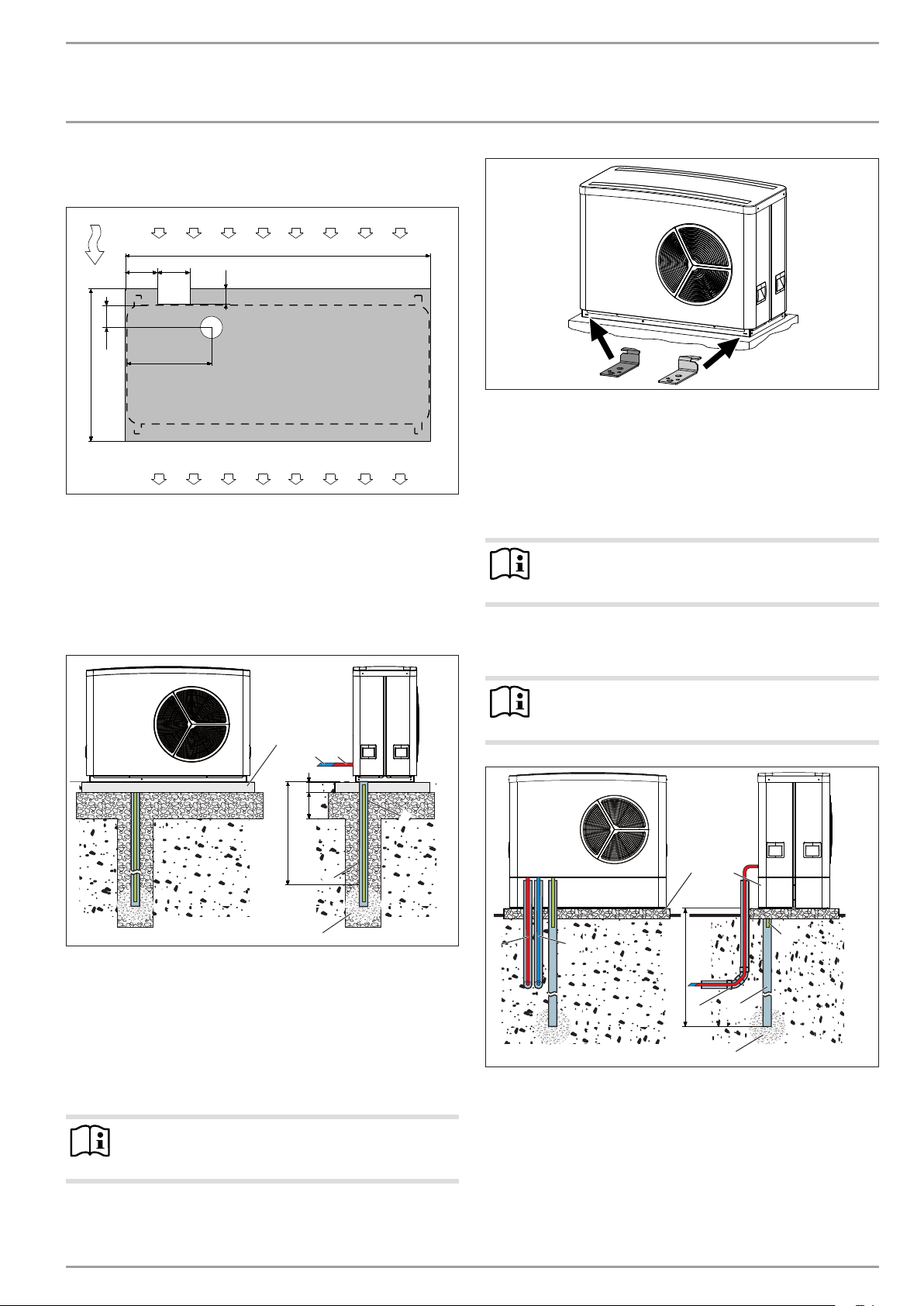
9.4.2 Example: T-support SK-WPL
1
A Depth of frost line
B 300
1 Heating flow
2 Heating return
3 Conduit for supply lines/cables
4 Foundation
5 T-support
6 Gravel bed
7 Drainage pipe
8 Condensate drain
9 Cover
Observe the static limits of the T-support used.
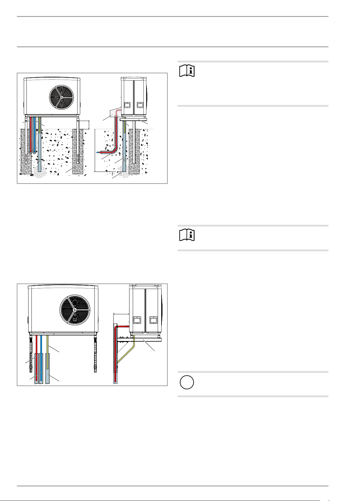
9.4.3 Example: Wall mounting support WK 2
2
4
9
B
A
3
7
6
Note
To prevent disturbance due to structure-borne noise
transmission, never install the wall mounting bracket on
the external walls of living areas or bedrooms.
Install the wall mounting bracket, for example, on a
garage wall.
8
5
9.5 Installing supply lines and supply cables
The supply lines are all electric cables plus the heating flow and
return lines.
Use only weather-resistant cables, e.g. NYY.
Protect the flow and return lines against frost, with sufficient
thermal insulation. Provide the thermal insulation in accordance with applicable regulations.
Also protect all supply lines/cables against humidity, damage
D0000050006
and UV radiation by means of a conduit.
Protect the supply lines and cables routed through the
ground from moisture and damage by routing them through
a conduit.
Protect all pipe fixings and outer wall transitions with an-
ti-vibration insulation.
Note
When routing the condensate hose, observe chapter "Installation / Condensate drain".
9.6 WPM heat pump manager
A WPM heat pump manager is required to operate the appliance.
This controls the entire heating system.
≥300
3
1
2
1 Heating flow
2 Heating return
3 Condensate drain
4 Drainage pipe
5 Wall mounting bracket
Observe the static limits of the wall mounting support used.
4
9.7 Buffer cylinder
A buffer cylinder is recommended to ensure trouble-free appliance
operation.
The buffer cylinder provides hydraulic separation of the volume
flows in the heat pump circuit and heating circuit, and also serves
as an energy source for defrosting.
When operating without a buffer cylinder, observe the de-
5
D0000058719
tails specified in chapter „Minimum flow rate with individual
room controller by means of FEK / FE7 in the case of systems
without buffer cylinder“.
Material losses
!
A buffer cylinder with diffusion-proof insulation is essential for cooling mode.
10 |WPL A | WPL AC | WPL AS | WPL ACS www.stiebel-eltron.com
Page 11
INSTALLATION
Installation
9.8 Preparing the electrical installation
WARNING Risk of electrocution!
Carry out all electrical connection and installation work
in accordance with national and regional regulations.
WARNING Risk of electrocution!
Use a permanent connection to the power supply. The
appliance must be able to be separated from the power
supply by an isolator that disconnects all poles with at
least 3mm contact separation. This requirement can be
met by contactors, isolators, fuses, etc.
Material losses
!
The specified voltage must match the mains voltage. Observe the type plate.
Material losses
!
Provide separate fuses for the 3 power circuits (for the
appliance, the electric emergency/booster heater and the
control unit).
Lay the relevant pipe cross-sections. Observe the applicable
national and regional regulations.
Fuse protection Assignment Cable cross-section
10. Installation
Note
The device is designed in such a way that it can be positioned and connected without removing the cover or
side panels.
10.1 Handling
Use the recessed grips provided at the sides.
Material losses
!
Protect the appliance against heavy impact during
transport.
Only allow the appliance to be tilted during transport for a short
time to one of its longitudinal sides. The longer the appliance is
tilted, the greater the distribution of refrigerant oil in the system.
Wait approx. 30 minutes before starting the appliance after it has
been tilted.
10.2 Siting
When installing the appliance, observe the air intake
direction.
Position the standard appliance on the prepared substrate.
1x C 20 A
1x C 35 A
3x C 16 A
2x B 16 A
3x B 16 A
1x B 16 A Control 1.5 mm²
The electrical data is provided in the "Specification" chapter. You
require a J-Y (St) 2x2x0.8mm² cable as BUS cable.
Note
The appliance contains an inverter for the variable speed
compressor. In case of a fault inverters can cause DC
residual currents. If RCDs are provided, they have to be
type B AC/DC-sensitive.
A DC residual current can block type A RCDs.
Heat pump
(single phase)
WPL 15 AS
WPL 15 ACS
Heat pump
(single phase)
WPL 25 AS
WPL 25 ACS
Heat pump
(3-phase)
WPL 20 A
WPL 20 AC
WPL 25 A
WPL 25 AC
Electric emergency/booster
heater WPL15AS
WPL15ACS
WPL25AS
WPL25ACS
Electric emergency/booster heater
WPL 20 A
WPL 20 AC
WPL25A
WPL25AC
Make sure that the appliance power supply is dis-
connected from the fuse board/distribution panel.
2.5 mm² for routing above the surface
4.0 mm² for routing through a wall
6.0 mm² for routing through a wall
2.5 mm²
2.5 mm²
2.5 mm²
Note
The appliance can be secured to a foundation with screws
as additional protection against tipping over.
Use the accessories that were in place to secure the
appliance to the transport pallet.
10.3 Heating water connection
The heat pump heating system must be connected by a qualified
contractor in accordance with the water installation drawings,
which are part of the technical guides.
Thoroughly flush the pipework before connecting the heat
pump. Foreign bodies, such as welding beads, rust, sand,
sealant, etc. can impair the operational reliability of the heat
pump.
Connect the heat pump on the heating water side. Check for
tightness.
Ensure the correct connection of the heating flow and return.
To facilitate connection to the heating system, push-fit connectors
are enclosed with the appliance (see chapter "Fitting the push-fit
connectors").
Provide the thermal insulation in accordance with applicable
regulations.
When designing the heating circuit, observe the internal
pressure difference (see chapter "Specification / Data table").
www.stiebel-eltron.com WPL A | WPL AC | WPL AS | WPL ACS | 11
Page 12
INSTALLATION
Installation
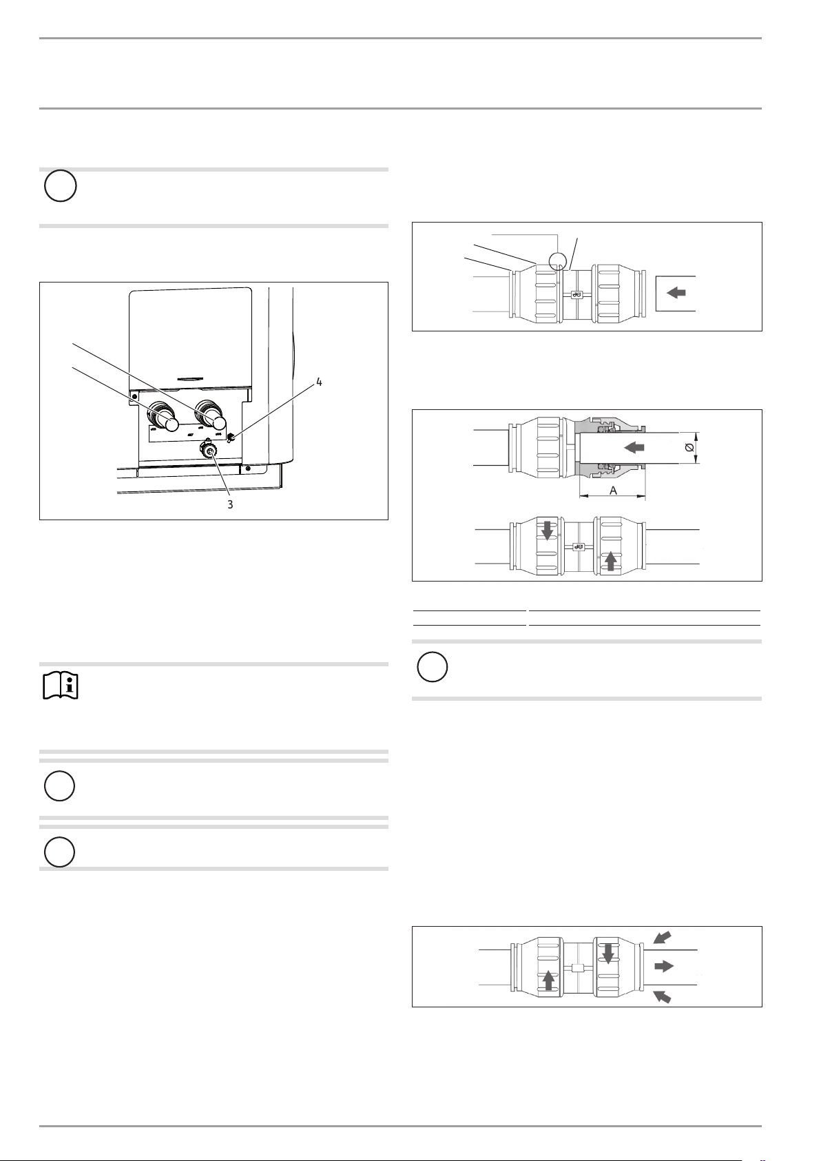
10.4 Flow and return connection
Material losses
!
Insulate the heating flow and return lines for cooling
mode with vapour diffusion-proof material.
Take the position of the heating flow and return from the fol-
lowing figure:
1
2
4
3
1 Heating flow
2 Heating return
3 Drain
4 Ventilation
Connect the heat pump to the heating circuit. Check for
tightness.
Making the push-fit connection
The connector must be in its relaxed position before the pipe is
inserted. In this position, there is a small gap between the screw
cap and main body.
3
2
1
1 Retainer
2 Screw cap
3 Gap between screw cap and main body
4 Main body
26�03�01�1871
Pipe Ø 28 mm
Depth of insertion A 44 mm
4
26�03�01�0693
26�03�01�0693
10.5 Fitting the push-fit connector
Note
The plastic push-fit connectors are not suitable for installation in the DHW line or the solar circuit.
Only install the push-fit connectors in the heating or
brine circuits.
Material losses
!
Tighten the screw cap of the push-fit connector by hand.
Never use a tool.
Material losses
!
Support sleeves are required when using plastic pipes.
How the push-fit connectors work
The push-fit connectors are equipped with a retainer with stainless steel serrations and an O-ring seal. In addition, the pushfit connectors are equipped with the “twist and lock” function.
Simply turning the screw cap by hand will secure the pipe in the
connector and push the O-ring against the pipe to seal it.
Material losses
!
Pipe ends must be deburred.
Always use a pipe cutter to trim pipes.
Push the pipe through the O-ring into the push-fit connector
until it reaches the prescribed insertion depth.
Tighten the screw cap by hand against main body as far as it
will go. This locks the push-fit connection.
Undoing the push-fit connection
If the push-fit connectors later need to be undone, proceed as
follows:
Turn the screw cap anti-clockwise until there is a narrow gap
of approx. 2mm. Press the retainer back with your fingers
and hold on to it.
Pull out the inserted pipe.
26�03�01�0693
12 |WPL A | WPL AC | WPL AS | WPL ACS www.stiebel-eltron.com
Page 13

INSTALLATION
Installation
10.6 Oxygen diffusion
Material losses
!
Avoid open heating systems and plastic pipes in underfloor heating systems which are permeable to oxygen.
In underfloor heating systems with plastic pipes that are permeable to oxygen and in open vented heating systems, oxygen
diffusion may lead to corrosion on the steel components of the
heating system (e.g. on the indirect coil of the DHW cylinder, on
buffer cylinders, steel heating elements or steel pipes).
Material losses
!
The products of corrosion (e.g. rusty sludge) can settle in
the heating system components and can result in a lower
output or fault shutdowns due to reduced cross-sections.
10.7 Filling the heating system
Fill the heating system via the drain (see chapter "Specifica-
tion / Dimensions").
10.7.1 Water quality
Before the system is filled, a fill water analysis must be made
available. This may, for example, be requested from the relevant
water supply utility.
To avoid damage as a result of scaling, it may be necessary to
soften or desalinate the fill water. The fill water limits specified
in chapter "Specification / Data table" must always be observed.
Recheck these limits 8-12 weeks after commissioning and as
part of annual system maintenance.
Note
With conductivity of >1000μS/cm, desalination treatment
is recommended in order to avoid corrosion.
Note
If you treat the fill water with inhibitors or additives, the
same limits as for desalination apply.
Note
Suitable appliances for water softening, as well as for
filling and flushing heating systems, can be obtained via
trade suppliers.
10.7.2 Venting the heating system
1
1 Ventilation
Vent the pipework by activating the ventilation.
10.8 Minimum flow rate
For heating operation without buffer cylinder, ensure the minimum flow rate and the availability of defrost energy.
10.9 Setting the flow rate on the heating side
Material losses
!
For operation without a buffer cylinder, it is essential
that the electric emergency/booster heater (DHC) is connected.
The appliance is designed in such a way that no buffer cylinder
is required to provide hydraulic separation of the flow in the heat
pump circuit and the heating circuit in conjunction with panel
heating systems.
We recommend the use of a buffer cylinder for installations with
several heating circuits.
The setting is made in heat pump mode. For this, make the following settings first:
Temporarily remove the fuse from the electric emergency/
booster heater to isolate the emergency/booster heater from
the power supply. Alternatively, switch OFF the second heat
generator.
Operate the appliance in heating mode.
26�03�01�1871
10.9.1 Minimum flow rate with individual room controller by
means of FEK / FE7 in systems without buffer cylinder
For systems without a buffer cylinder, in menu „SETTINGS/ HEATING/ STANDARD SETTING“, set parameter „BUFFER OPERATION“
to „OFF“.
In such cases, one or more heating circuits in the heating system
must be left open. Ensure the minimum flow rate (see „Specification / Data table“) by means of the correspondingly opened heating circuits (see table „Design recommendation for an underfloor
heating system inside the lead room“).
www.stiebel-eltron.com WPL A | WPL AC | WPL AS | WPL ACS | 13
Page 14

INSTALLATION
Installation
Design recommendation for underfloor heating system inside the lead room:
Material losses
!
A buffer cylinder with diffusion-proof insulation is essential for cooling mode.
Minimum flow
rate
l/h l m² n x m m² n x m
WPL 15 AS 700 16 21 3x70 21 2x70
WPL 15 ACS 700 16 21 3x70 21 2x70
WPL 20 A 1000 29 28 4x70 32 3x70
WPL 20 AC 1000 29 28 4x70 32 3x70
WPL 25 A 1000 29 28 4x70 32 3x70
WPL 25 AS 1000 29 28 4x70 32 3x70
WPL 25 AC 1000 29 28 4x70 32 3x70
WPL 25 ACS 1000 29 28 4x70 32 3x70
Buffer cylinder always
required
WPL 15 AS no 100 200 yes
WPL 15 ACS no 100 200 yes
WPL 20 A no 200 400 yes
WPL 20 AC no 200 400 yes
WPL 25 A no 200 400 yes
WPL 25 AS no 200 400 yes
WPL 25 AC no 200 400 yes
WPL 25 ACS no 200 400 yes
Install the open heating circuit(s) in the lead room (room
where the external programming unit of the heat pump
control unit is installed, such as in the living room). The individual room can then be controlled either with the external
programming unit or directly by adjusting the heating curve
or the room influence.
Fully open the heating circuit(s) in the lead room.
Close all other heating circuits.
If an overflow valve has been installed in the heating system,
fully close this overflow valve in order to determine the minimum flow rate.
In combination with an hydraulic module, cylinder and hydraulic
module or integral cylinder:
Under menu item “COMMISSIONING/ HEATING” set the pa-
rameter “HEATING CIRC PUMP RATE” (heating circuit pump
rate) so that the minimum flow rate required for system op-
Minimum water content of buffer
cylinder or open circuits
Recommended buffer cylinder
volume, underfloor heating
Composite pipework 16 x 2mm
/ rout ing gap 10cm
Lead room
floor area
Number of circuits
Recommended buffer cylinder
volume, radiators
Composite pipework 20x2.25mm /
rout ing gap 15cm
Lead room
floor area
Number of circuits
Activat ing the integral
emergency/booster
heater
10.9.2 Minimum flow rate for systems with buffer cylinder
When using a buffer cylinder, in menu „SETTINGS/ HEATING/
STANDARD SETTING“, set parameter „BUFFER OPERATION“ to
„ON“.
In combination with an hydraulic module, cylinder and hydraulic
module or integral cylinder:
Under menu item “COMMISSIONING/ HEATING” set the pa-
rameter “HEATING CIRC PUMP RATE” so that the nominal
flow rate required for system operation is assured (see chapter “Specification/ Data table”).
If the appliance is operated on its own with a WPM:
Set the buffer charging pump so that the nominal flow rate
required for system operation is assured.
The current flow rate can be called up in the menu „INFO/ HEAT
PUMP INFO/ PROCESS DATA“ under „WP WATER FLOW RATE“.
eration is assured (see chapter “Specification / Data table”).
If the appliance is operated on its own with a WPM:
Set the heating circuit pump so that the minimum flow rate
required to operate the system is safeguarded.
The current flow rate can be called up in the menu „INFO/ HEAT
PUMP INFO/ PROCESS DATA“ under „WP WATER FLOW RATE“.
14 |WPL A | WPL AC | WPL AS | WPL ACS www.stiebel-eltron.com
Page 15

INSTALLATION
Power supply
10.10 Condensate drain
A condensate drain connector is factory fitted to the defrost pan
to enable any condensate that may form to drain off.
1
1 Condensate drain
If required, you may install a supplementary heating facility inside
the condensate drain pipe on site. We recommend that you install
a supplementary heating facility if the routing of the condensate
hose means it is at risk of frost or is fully exposed to the elements.
If the appliance is mounted on a wall mounting bracket or T-support, a supplementary heating facility must be fitted.
If the appliance is mounted on a wall bracket or T-support,
attach a condensate hose to the condensate drain.
Protect the condensate hose against frost with sufficient
thermal insulation.
11. Power supply
WARNING Electrocution
Before any work, isolate the appliance from the
power supply at the control panel.
Following isolation from the mains supply, parts of the
appliance may remain live for up to 2 minutes since
the capacitors still have to discharge into the inverter.
The connection must only be carried out by a qualified contractor
and in accordance with these instructions.
Permission to connect the appliance may need to be obtained from
your local power supply utility.
Note
Observe the operating and installation instructions for
the WPM heat pump manager.
The terminals are located in the wiring chamber of the appliance.
Observe chapter "Preparing the electrical installation".
26�03�01�1868
Use appropriate electrical cables in accordance with local
regulations for all connections.
Access to the wiring chamber
Material losses
!
Ensure the condensate hose is not kinked. Route the hose
with a slope.
After routing the condensate hose, check that the condensate
can drain correctly.
Please also observe the chapter "Electrical connection of sup-
plementary heating facility".
10.11 External second heat generator
For dual mode systems, always connect the heat pump into the
return of the second heat generator (e.g. oil boiler).
10.12 Safety temperature controller for underfloor
heating system STB-FB
Material losses
!
In case of failure, in order to prevent an excessively high
flow temperature in the underfloor heating system, we
generally recommend the use of a safety temperature
controller to limit the system temperature.
D000003535626�03�01�1862
Push the cover upwards.
www.stiebel-eltron.com WPL A | WPL AC | WPL AS | WPL ACS | 15
Page 16

INSTALLATION
Power supply
Connect the electric emergency/booster heater if you want to
utilise the following appliance functions:
1 2
1 Strain relief
2 Wiring chamber
Route cables and leads through the strain reliefs.
If space behind the appliance is limited, the wiring chamber can
be folded out.
Appliance function
Mono energetic operation
Emergency mode Should the heat pump suffer a fault that prevents its
Heat-up program
(only for underfloor
heating systems)
26�03�01�1865
Pasteurisation
control
Effect of the electric emergency/booster
heater
If the heat pump cannot reach the dual mode point, the
electric emergency/booster heater ensures both the
heating operation and the provision of high DHW temperatures.
continued operation, the heating output will be covered
by the electric emergency/booster heater.
Where return temperatures are <25°C, the electric
emergency/booster heater must provide the necessary
heat for screed drying.
With these low system temperatures, the drying heat
must not be provided by the heat pump, otherwise the
frost protection of the appliance can no longer be guaranteed during the defrost cycle.
When the heat-up program has ended, you can disconnect the electric emergency/booster heater if it is not
required for the appliance operation.
Please note that during the heat-up program, the emergency mode cannot be selected.
The electric emergency/booster heater starts automatically when the pasteurisation control is active in order to
regularly heat the DHW to 60°C to protect it against the
growth of legionella bacteria.
Connect cables according to the following diagram.
Earth the LV lead by inverting the screen over the external
sheath and clamping it under the earth terminal.
Then check the function of the strain relief fittings.
26�03� 01�186326�03�01�1864
16 |WPL A | WPL AC | WPL AS | WPL ACS www.stiebel-eltron.com
Page 17

INSTALLATION
Power supply
11.1 Power connection WPL15AS| WPL15ACS
4 3215
X2
T
L
H
„+“
BUS
N LL N L N
X5 / DHC X3 / WP X4 / Steuerung
1/N/PE~230/50
C 32A
3,0 kW L N PE
3,2 kW L N PE
6,2 kW L N L N PE
1/N/PE~230/50
C 20A
1 X5 Electr ic emergency/booster heater (DHC)
L, N, L, N, PE
Connected load Terminal allocat ion
3,0 kW L N PE
3,2 kW L N PE
6,2 kW L N L N PE
2 X3 Compressor (inverter)
L, N, PE
3 X4 Control voltage
Power supply: L, N, PE
4 X2 Low voltage (BUS cabl e)
BUS High H
BUS Low L
BUS earth
BUS "+" (is not connected)
5 Earth terminal for screening the LV lead
The tested appliance conforms to IEC 61000-3-12.
The maximum permissible mains impedance is indicated in chapter “Specification / Data table”.
ERR
1/N/PE~230/50
C 16A
LON-
N
11.2 Power connection WPL20A| WPL20AC|
WPL25A| WPL25AC
4 3215
X2
T
L
H
„+“
BUS
D0000037825
1 X5 Electr ic emergency/booster heater (DHC)
L1, L2, L3, N, PE
Connected load Terminal allocat ion
2,6 kW L1 PE
3,0 kW L2 PE
3,2 kW L3 PE
5,6 kW L1 L2 PE
5,8 kW L1 L3 PE
6,2 kW L2 L3 PE
8,8 kW L1 L2 L3 PE
2 X3 Compressor (inverter)
L1, L2, L3, N, PE
3 X4 Control voltage
Power supply: L, N, PE
4 X2 Low voltage (BUS cabl e)
BUS High H
BUS Low L
BUS earth
BUS "+" (is not connected)
5 Earth terminal for screening the LV lead
L2 L3L1 N L2 L3L1 N
3/N/PE~400/50
X5 / DHC X3 / WP X4 / Steuerung
C 16A
2,6 kW L1 N PE
3,0 kW L2 N PE
3,2 kW L3 N PE
5,6 kW L1 L2 N PE
5,8 kW L1 L3 N PE
6,2 kW L2 L3 N PE
8,8 kW L1 L2 L3 N PE
3/N/PE~400/50
C 16A
ERR
1/N/PE~230/50
C 16A
LON-
N
26�03�01�1859
www.stiebel-eltron.com WPL A | WPL AC | WPL AS | WPL ACS | 17
Page 18

INSTALLATION
Power supply
11.3 Power connection WPL25AS| WPL25ACS
4 3215
X2
T
L
H
„+“
BUS
N LL N L N
X5 / DHC X3 / WP X4 / Steuerung
1/N/PE~230/50
C 32A
3,0 kW L N PE
3,2 kW L N PE
6,2 kW L N L N PE
1/N/PE~230/50
C 36A
1 X5 Electr ic emergency/booster heater (DHC)
L, N, L, N, PE
Connected load Terminal allocat ion
3,0 kW L N PE
3,2 kW L N PE
6,2 kW L N L N PE
2 X3 Compressor (inverter)
L, N, PE
3 X4 Control voltage
Power supply: L, N, PE
4 X2 Low voltage (BUS cabl e)
BUS High H
BUS Low L
BUS earth
BUS "+" (is not connected)
5 Earth terminal for screening the LV lead
LON-
ERR
1/N/PE~230/50
C 16A
N
Closing the wiring chamber
1 Serrated washer
2 Screw
D0000037825
Secure the cover with the screw and serrated washer.
Connect the following components to the heat pump manag-
er in accordance with the technical guides:
- Circulation pump for the heat consumer side
- Outside temperature sensor
- Return sensor (only for operation with buffer cylinder)
11.4 Electrical connection of supplementary heating
facility
If required, you can mount a ribbon heater on the condensate pan
and the condensate hose on site. We recommend that you install
a ribbon heater if the routing of the condensate hose means it is
at risk of frost or is fully exposed to the elements. A ribbon heater
must be fitted if the condensate hose is installed on a wall mounting panel. See also chapter “Electrical connection”.
Access to the wiring chamber
1
2
D0000035356
Remove the cover.
18 |WPL A | WPL AC | WPL AS | WPL ACS www.stiebel-eltron.com
26�03�01�1544
Page 19

INSTALLATION
Power supply
Closing the wiring chamber
A.
1 Electrical connection for ribbon heater
Power supply: L, N, PE
B.
1
D0000035975
26�03�01�1867
Position the cover on the appliance.
Secure the cover with the four screws.
D0000035976
D0000033168
www.stiebel-eltron.com WPL A | WPL AC | WPL AS | WPL ACS | 19
Page 20

INSTALLATION
Commissioning
12. Commissioning
A WPM heat pump manager is required to operate the appliance.
All necessary adjustments prior to and during operation are made
on this device.
Only qualified contractors may carry out the adjustments on the
heat pump manager commissioning report, commission the appliance and instruct the owner in its use.
Carry out commissioning in accordance with these installation
instructions and the operating and installation instructions of the
heat pump manager. Our customer service can assist with commissioning, which is a chargeable service.
Where this appliance is intended for commercial use, the rules of
the relevant Health & Safety at Work Act must be observed at commissioning. For further details, check your local authorising body.
12.1 Checks before commissioning
Before commissioning, check the following points.
12.1.1 Heating system
- Have you filled the heating system to the correct pressure,
and opened the quick-action air vent valve?
12.1.2 Temperature sensor
- Have you correctly positioned and connected the outside
temperature sensor and the return temperature sensor (in
conjunction with a buffer cylinder)?
12.1.3 High limit safety cut-out
In ambient temperatures of below -15 °C it is possible that the high
limit safety cut-out of the electrical emergency/booster heater
may trip.
Check whether the high limit safety cut-out has tripped.
1
26�03�01�1872
1 High limit safety cut-out reset button
Reset the high limit safety cut-out by pressing the reset
button.
12.1.4 Power supply
- Have you correctly connected the power supply?
12.2 Using the appliance with an external second
heat generator
The appliance is factory set for Compressor operation with an
electric emergency/booster heater. If the appliance is used in dual
mode with an external second heat generator or as a module with
an additional identical heat pump, you must set the DIP switch
to WP Type 4 (see chapter "Troubleshooting / Checking the IWS
DIP switch settings / Compressor mode with an external second
heat generator").
1
1 Electric emergency/booster heater
Remove the cause of the fault.
12.3 Settings
12.3.1 Heating curve adjustment
The efficiency of a heat pump decreases as the flow temperature
rises. The heating curve should therefore be adjusted with care.
Heating curves that are set too high cause the zone valves and
thermostatic valves to close, which may lead to the minimum flow
rate required for the heating circuit not being achieved.
Observe the WPM operating and installation instructions.
The following steps will help you to adjust the heating curve correctly:
- Fully open thermostatic or zone valves in a lead room (e.g.
26�03�01�1880
26�03�01�1880
living room and bathroom).
We do not recommend installing thermostatic or zone valves
in the lead room. Control the temperature for these rooms
via remote control.
- At different outside temperatures (e.g. –10°C and +10°C),
adjust the heating curve so the required temperature is set in
the lead room.
20 |WPL A | WPL AC | WPL AS | WPL ACS www.stiebel-eltron.com
Page 21

INSTALLATION
Maintenance
Standard values to begin with:
Parameter Underfloor heating
Heating curve 0.4 0.8
Control response time 25 50
Comfort temperature 21°C 23°C
If the room temperature is not high enough in spring and autumn
(approx. 10 °C outside temperature), raise the „COMFORT TEMPERATURE“ parameter in the heat pump manager menu under
„SETTINGS / HEATING / HEATING CIRCUIT“.
Note
If no remote control is installed, raising the "COMFORT
TEMPERATURE" parameter leads to a parallel offset of
the heating curve.
Increase the „HEATING CURVE“ parameter, if the room temperature is not high enough when outside temperatures are low.
If you raise the „HEATING CURVE“ parameter, adjust the zone valve
or thermostatic valve in the lead room to the required temperature
when outside temperatures are high.
Material losses
!
Never reduce the temperature in the entire building by
closing all zone or thermostatic valves, instead use the
setback programs.
When everything has been implemented correctly, the system
can be heated to its maximum operating temperature and vented
once again.
system
Radiator heating
system
12.4 Operation and control
Material losses
!
Never interrupt the power supply, even outside the heating season. The system's active frost protection is not
guaranteed if the power supply is interrupted.
The system does not have to be switched off in summer. The heat
pump manager has an automatic summer / winter changeover.
12.5 Decommissioning
If the system is to be taken out of use, set the WPM to standby.
This retains the safety functions designed to protect the system
(e.g. frost protection).
Material losses
!
If the heat pump and frost protection are completely
switched off, drain the system on the water side.
13. Maintenance
We recommend that you perform an annual inspection (to establish the current condition of the system), and as required have
maintenance carried out (to return the system to its original condition).
Check the condensate drain (visual inspection). Remove contaminants and blockages immediately.
Material losses
!
With underfloor heating systems, observe the maximum
permissible temperature for the system.
12.3.2 Other settings
For operation with and without buffer cylinder, observe
chapter „Operation / Menu structure / Menu SETTINGS/
STANDARD SETTING/ BUFFER OPERATION“ in the operating
and installation instructions of the WPM.
When using the heat-up program
If you use the heat-up program, make the following settings on
the WPM:
Initially set parameter „DUAL MODE TEMP HZG“ to 30°C.
Then set parameter „LOWER APP LIMIT HZG“ to 30°C.
Note
After completing the heat-up process, reset the parameters "DUAL MODE TEMP HZG" and "LOWER APP LIMIT HZG"
to their respective standard values or to the respective
system values.
1.
2.
1
1 Inspection port
Material losses
!
Keep the air discharge and intake apertures free from
snow and ice.
Remove any leaves or other foreign bodies from the evaporator
fins periodically.
D0000037831
www.stiebel-eltron.com WPL A | WPL AC | WPL AS | WPL ACS | 21
Page 22

INSTALLATION
Troubleshooting
14. Troubleshooting
WARNING Electrocution
Before any work, isolate the appliance from the
power supply at the control panel.
Following isolation from the mains supply, parts of the
appliance may remain live for up to 2 minutes since
the capacitors still have to discharge into the inverter.
Note
Please observe the heat pump manager operating and
installation instructions.
If a fault cannot be located during service using the heat pump
manager, open the control panel in emergencies and check the
IWS settings. This check must only be carried out by a qualified
contractor.
14.1 Checking the IWS DIP switch settings
Carry out the following steps to make the IWS accessible.
1
26�03�01�1870
1 IWS
Lift the cover.
IWS
1
Remove the cover.
Remove the bracket highlighted in grey.
BA
BA
26�03�01�1866
4
1 LEDs
2 DIP switch (WP-Typ)
3 Reset button
4 DIP switch (BA)
DIP switch (WP-Typ)
With the DIP switch ("WP-Typ"), you can select the various heat
pump types on the IWS.
Factory setting
Compressor mode with electric emergency/booster heater
3
WP - Typ
26�03� 01�1869
ON
2
C26�03�01�0921
1 2 3 4
Check whether the DIP switch is set correctly.
22 |WPL A | WPL AC | WPL AS | WPL ACS www.stiebel-eltron.com
D0000057054
Page 23

INSTALLATION
BA
BA
Troubleshooting
Compressor mode with an external second heat generator
Damage to the appliance and environment
!
In this case, do not connect the electric emergency/booster heater.
If the appliance is operated in dual mode with an external second
heat source, set the DIP switch as follows:
Set the DIP switch as follows.
WP - Typ
ON
1 2 3 4
DIP switch (BA)
Check whether the DIP switch(BA) is set correctly.
Heating operation
BA
14.1.1 Closing the wiring chamber
D0000057055
26�03�01�1867
Position the cover on the appliance.
Secure the cover with the four screws.
Cooling operation
ON
1 2 3 4
ON
1 2 3 4
BA
14.2 Light emitting diodes (LEDs)
D0000057052
D0000051579
1 LEDs
2 Reset button
The following table shows the meaning of the LEDs of the IWS.
LED indicator Meaning
Red LED flashes Single fault. Appliance stops and restarts after 10
Red LED illuminates
Green LED (centre)
flashes
Green LED (centre) illuminates
minutes, and the LED extinguishes.
More than 5 faults within 2 hours run. The appli-
ance is shut down permanently and only restarts
following a reset on the IWS. The internal fault
counter will then be reset. The appliance can be restarted after 10 minutes. The LED extinguishes.
The heat pump is initialising.
The heat pump was initialised successfully and the
connection with the WPM is active.
1
2
26�03�01�0921
www.stiebel-eltron.com WPL A | WPL AC | WPL AS | WPL ACS | 23
Page 24

INSTALLATION
Troubleshooting
Faults indicated by the red LED:
- High pressure fault
- Low pressure fault
- Other fault and
- Hardware fault on the IWS (see fault list)
14.3 Reset button
If the IWS was not initialised successfully, you can reset the settings with this button.
For this, also observe chapter "Reinitialising the IWS" in the
heat pump manager operating and installation instructions.
14.4 Resetting the high limit safety cut-out
The electric emergency/booster heater stops if the heating water
temperature exceeds 85 °C, for example on account of a low flow
rate.
14.5 Fan noise
The heat pump draws heat from the outdoor air. This causes the
outdoor air to cool down. At outside temperatures of 0°C to 8°C,
the air may be cooled to below freezing point. If under these
conditions precipitation occurs in the form of rain or fog, ice may
form on the air grille, the fan blades or the air routing. If the fan
comes into contact with this ice, noise develops.
How to remedy rhythmically scratching or grinding noises:
Check whether the condensate drain is free from obstruction.
Check whether the design output and temperature are set
correctly. Ice formation is particularly pronounced when
a high heating output is demanded at moderate outside
temperatures.
Carry out a manual defrost, repeatedly if required, until the
fan runs free again. For this, observe the information in the
operating and installation instructions for the WPM.
At outside temperatures above + 1°C, switch the appliance
off for around 1hour or switch it over to emergency mode.
After this, the ice should have melted.
Check whether the appliance is installed in line with the in-
stallation conditions.
If the noises occur frequently, notify customer support.
1 Electric emergency/booster heater
Remove the cause of the fault.
1
1 High limit safety cut-out reset button
Reset the high limit safety cut-out by pressing the reset
button.
Check whether the heating water is being circulated at a suf-
ficient flow rate.
26�03�01�1880126�03�01�1880
26�03�01�1872
24 |WPL A | WPL AC | WPL AS | WPL ACS www.stiebel-eltron.com
Page 25

INSTALLATION
Troubleshooting
www.stiebel-eltron.com WPL A | WPL AC | WPL AS | WPL ACS | 25
Page 26

INSTALLATION
100
Specication
15. Specification
15.1 Dimensions and connections
WPL15AS| WPL15ACS
d45
410
70
1160
490
1270
900
WPL 15 AS WPL 15 ACS
e01 Heating flow
Diameter mm 28 28
e02 Heating return
Diameter mm 28 28
d45 Condensate drain Diameter mm 22 22
d47 Drain
g01 Air intake
g02 Air discharge
Type of connection Plug-in connection Plug-in connection
Type of connection Plug-in connection Plug-in connection
g01 g02
157
593
e02
100
e01
176
82
d47
D0000034131
26 |WPL A | WPL AC | WPL AS | WPL ACS www.stiebel-eltron.com
Page 27

INSTALLATION
1045
100
Specication
WPL20A| WPL20AC| WPL25A| WPL25AS| WPL25AC| WPL25ACS
d45
410
490
1380
1490
g01 g02
157
WPL 20A WPL 20 AC WPL 25 A WPL 25 AS WPL 25 AC WPL 25 ACS
e01 Heating flow
Diameter mm 28 28 28 28 28 28
e02 Heating return
Diameter mm 28 28 28 28 28 28
d45 Condensate
drain
d47 Drain
g01 Air intake
g02 Air discharge
Type of connection Plug-in connection Plug-in connection Plug-in connection Plug-in connection Plug-in connection Plug-in connection
Type of connection Plug-in connection Plug-in connection Plug-in connection Plug-in connection Plug-in connection Plug-in connection
Diameter mm 22 22 22 22 22 22
593
e02
e01
100
176
82
d47
D0000028296
www.stiebel-eltron.com WPL A | WPL AC | WPL AS | WPL ACS | 27
Page 28

INSTALLATION
3121
F5
11
P1=2600W
AB
K6
U V W
M1
1 3
2 4
K2
X2 Busanschluss WP
Y1
B12
T
B13
T
B9
T
B11
T
V1
M8
M7
M
B2
T
H L T “+”
L
N
M6
M
1~
1 2 3 4 5 6 7
X39
X36
4
3
2
1
X35
6
5
4
3
2
1
X34
Heizungsvorlauf
+12...+18V
GND
ND 4...20mA
HD 4...20mA
MD 4...20mA
Heißgas
7
6
5
4
3
2
1
X30
3
2
1
X37
5
4
3
2
1
X33
5
4
3
2
1
Lüfter Drehz.
Lüfter +10V
Lüfter 0...10V
Lüfter GND
Heizungsrücklauf
Außenluft
Verdichtereintritt
Verdampferaustritt
GND
Einspritzung
CAN GND
CAN L
CAN H
+12V
Phase 1
Phase 2
Phase 3
Phase 4
+12V
Phase 1
Phase 2
Phase 3
Phase 4
Frostschutz
Verflüssigeraustritt
Fortluft
Ölsumpftemperaturnc0-5V Eingang
GND
A2
(IWS III)
X42
3 2 1
p
P1
Specication
15.2 Wiring diagram for WPL15AS| WPL15ACS| WPL25AS| WPL25ACS (single-phase)
X5 Netz DHC
L N L N
X3 Netz WP
L N
L1 L2
FROM AC
A4
TO DRIVE
L1 L2
X27/7
X23
X27/1
bl
sw
M6
F4
X8
X27/2
X27/8
X4 Netz Steuerung
ON ERR L N
6 5 4 3 2 1
X23
K7
AB
X1
K2
A2 A1
F3
> p
L N PE
3222
12
T >
1
K6
3
1
K7
3
E1
P3=3200W
P2=3000W
A2 Integral heat pump control unit (IWS)
A3 Inverter compressor
B1 Heating flow temperature sensor - KTY
B2 Heating return temperature sensor - KTY
B5 Hot gas temperature sensor - PT1000
B6 Outdoor air temperature sensor - PT1000
B7 Compressor intake temperature sensor - PT1000
B8 Evaporator discharge temperature sensor - PT1000
B9 Frost protection temperature sensor - KTY
B10 Injection temperature sensor - PT1000
B11 Exhaust air temperature sensor - KTY
B12 Condenser outlet temperature sensor - KTY
B13 Oil sump temperature sensor - KT Y
E1 DHC
E2 Oil sump heater
F3 High pressure switch 42 bar
28 |WPL A | WPL AC | WPL AS | WPL ACS www.stiebel-eltron.com
A3
U V W PE
M
3~
X27/9
X46
N L L’
Y2
sw bl br
E2
F4 Fuse 10 A (fan)
F5 High limit safety cut-out for DHC
K2 Compressor start contactor L
K5 DHC relay
K6 DHC relay
K7 DHC relay
M1 Compressor motor
M6 Fan motor
M7 Electrical expansion valve stepper motor
M8 Electrical injection valve stepper motor
P1 High pressure sensor (42 bar)
P3 Low pressure sensor (16 bar)
P4 Mean pressure sensor (30 bar)
S1 Sinter filter coil
S2 Sinter filter coil
S3 Sinter filter coil
1 2 3
X29
1
2
3
4
5
6
7
8
9
10
11
12
X38
1
2
3
X43
1
2
3
4
X40
1
2
3
4
5
6
X7
X27/2
N
L
K2
nc
ERR
Rohrbegleitheizung
Abtauen
ON
HD
EVU
nc
nc
DHC1
DHC2
Ölsumpfheizung
GND
+5V
H
L
GND
Frequenzeing. 0...5V
+5V 20 mA
nc
nc
+12..+18V
D0000028167
Page 29

INSTALLATION
B12
T
B13
B9
B11
M7
B2
T
M6
X36
X35
X34
X30
X37
X33
3 2 1
P1
Specication
Lüfter Drehz.
Lüfter +10V
Lüfter 0...10V
Lüfter GND
Heizungsrücklauf
Außenluft
Verdichtereintritt
Verdampferaustritt
GND
Einspritzung
CAN GND
CAN L
CAN H
Heizungsvorlauf
+12...+18V
A2
(IWS III)
GND
ND 4...20mA
HD 4...20mA
MD 4...20mA
Heißgas
+12V
Phase 1
Phase 2
Phase 3
Phase 4
+12V
Phase 1
Phase 2
Phase 3
Phase 4
X2 Busanschluss WP
H L T “+”
4
3
2
1
6
5
4
3
2
1
3
2
1
7
6
5
4
3
2
1
5
4
3
2
1
5
4
3
2
1
X41
X41
X8 / F4
X6
1 2 3 4
1 2
X9
Frostschutz
Verflüssigeraustritt
Fortluft
Ölsumpftemperaturnc0-5V Eingang
1 2 3 4 5 6 7
X39
GND
X42
M
M
T
T
T
T
M8
V1 Flow sensor
X1 Internal distribution terminal
X2 External BUS terminal
X3 External power terminal
X4 External control terminal
X5 External DHC terminal
X6 4-pole terminal
X7 3-pole terminal
X8 2-pole terminal
X9 2-pole terminal
X23 Power supply earth block
X27 Earth stud
X29 IWS plug 12-pin - control unit
X30 IWS plug 3-pin - BUS
X33 IWS plug 5-pin - electrical expansion valve
X34 IWS plug 7-pin - sensors
3 2 1
p
P4
B5
3 2 1
p
p
T
P3
B1
T
T
B10
B8
T
T
B6
B7
L
M
N
1~
D0000028167
X35 IWS plug 6-pin - temperature sensors
X36 IWS plug 3-pin - fan
X37 IWS plug 5-pin - electrical injection valve
X38 IWS plug 3-pin - oil sump
X39 IWS plug 7-pin - temperature
X40 IWS plug 6-pin - HT special
X41 Link PCB ground
X42 Link PCB ground
X43 IWS plug, 3-pin
X46 Plug-in connector
Y1 Diverter valve - defrost
Y2 Diverter valve (only for WPL ACS)
www.stiebel-eltron.com WPL A | WPL AC | WPL AS | WPL ACS | 29
Page 30

INSTALLATION
K5
3
1
P1=2600W
3121
F5
11
K6
3
1
K7
3
AB
K5
U V W
M1
1 3 5 13
2 4 6 14
K2
S1
1 11
2 22
X2 Busanschluss WP
Y1
B12
T
B13
T
B9
T
B11
T
V1
M8
M7
M
B2
T
H L T “+”
L
N
M6
M
1~
1 2 3 4 5 6 7
X39
X36
4
3
2
1
X35
6
5
4
3
2
1
X34
Heizungsvorlauf
+12...+18V
GND
ND 4...20mA
HD 4...20mA
MD 4...20mA
Heißgas
7
6
5
4
3
2
1
X30
3
2
1
X37
5
4
3
2
1
X33
5
4
3
2
1
Lüfter Drehz.
Lüfter +10V
Lüfter 0...10V
Lüfter GND
Heizungsrücklauf
Außenluft
Verdichtereintritt
Verdampferaustritt
GND
Einspritzung
CAN GND
CAN L
CAN H
+12V
Phase 1
Phase 2
Phase 3
Phase 4
+12V
Phase 1
Phase 2
Phase 3
Phase 4
Frostschutz
Verflüssigeraustritt
Fortluft
Ölsumpftemperaturnc0-5V Eingang
GND
A2
(IWS III)
X42
3 2 1
p
P1
Specication
15.3 Wiring diagram for WPL20A| WPL20AC| WPL25A| WPL25AC (3-phase)
X5 Netz DHC
N L1 L2 L3
X3 Netz WP
L1 L2 L3 N
S3S2
X27/3
X27/7
X23
X27/1
bl
sw
M6
F4
X8
X27/2
X27/8
X4 Netz Steuerung
ON ERR L N
6 5 4 3 2 1
X23
X1
K6
AB
K7
AB
A2 A1
K2
F3
> p
L1 L2 L3 PE
3222
12
T >
1
E1
P3=3200W
P2=3000W
A2 Integral heat pump control unit (IWS)
A3 Inverter compressor
B1 Heating flow temperature sensor - KTY
B2 Heating return temperature sensor - KTY
B5 Hot gas temperature sensor - PT1000
B6 Outdoor air temperature sensor - PT1000
B7 Compressor intake temperature sensor - PT1000
B8 Evaporator discharge temperature sensor - PT1000
B9 Frost protection temperature sensor - KTY
B10 Injection temperature sensor - PT1000
B11 Exhaust air temperature sensor - KTY
B12 Condenser outlet temperature sensor - KTY
B13 Oil sump temperature sensor - KT Y
E1 DHC
E2 Oil sump heater
F3 High pressure switch 42 bar
F4 Fuse 10 A (fan)
30 |WPL A | WPL AC | WPL AS | WPL ACS www.stiebel-eltron.com
A3
U V W PE
M
3~
X27/9
X46
N L L’
Y2
sw bl br
E2
F5 High limit safety cut-out for DHC
K2 Compressor start contactor L
K5 DHC relay
K6 DHC relay
K7 DHC relay
M1 Compressor motor
M6 Fan motor
M7 Electrical expansion valve stepper motor
M8 Electrical injection valve stepper motor
P1 High pressure sensor (42 bar)
P3 Low pressure sensor (16 bar)
P4 Mean pressure sensor (30 bar)
S1 Sinter filter coil
S2 Sinter filter coil
S3 Sinter filter coil
V1 Flow sensor
X1 Internal distribution terminal
1 2 3
X29
1
2
3
4
5
6
7
8
9
10
11
12
X38
1
2
3
X43
1
2
3
4
X40
1
2
3
4
5
6
X7
X27/2
N
L
K2
nc
ERR
Rohrbegleitheizung
Abtauen
ON
HD
EVU
nc
nc
DHC1
DHC2
Ölsumpfheizung
GND
+5V
H
L
GND
Frequenzeing. 0...5V
+5V 20 mA
nc
nc
+12..+18V
D0000028167
Page 31

INSTALLATION
B12
T
B13
B9
B11
M7
B2
T
M6
X36
X35
X34
X30
X37
X33
3 2 1
P1
Specication
Lüfter Drehz.
Lüfter +10V
Lüfter 0...10V
Lüfter GND
Heizungsrücklauf
Außenluft
Verdichtereintritt
Verdampferaustritt
GND
Einspritzung
CAN GND
CAN L
CAN H
Heizungsvorlauf
+12...+18V
A2
(IWS III)
GND
ND 4...20mA
HD 4...20mA
MD 4...20mA
Heißgas
+12V
Phase 1
Phase 2
Phase 3
Phase 4
+12V
Phase 1
Phase 2
Phase 3
Phase 4
X2 Busanschluss WP
H L T “+”
4
3
2
1
6
5
4
3
2
1
3
2
1
7
6
5
4
3
2
1
5
4
3
2
1
5
4
3
2
1
X41
X41
X8 / F4
X6
1 2 3 4
1 2
X9
Frostschutz
Verflüssigeraustritt
Fortluft
Ölsumpftemperaturnc0-5V Eingang
1 2 3 4 5 6 7
X39
GND
X42
M
M
T
T
T
T
M8
X2 External BUS terminal
X3 External power terminal
X4 External control terminal
X5 External DHC terminal
X6 4-pole terminal
X7 3-pole terminal
X8 2-pole terminal
X9 2-pole terminal
X23 Power supply earth block
X27 Earth stud
X29 IWS plug 12-pin - control unit
X30 IWS plug 3-pin - BUS
X33 IWS plug 5-pin - electrical expansion valve
X34 IWS plug 7-pin - sensors
X35 IWS plug 6-pin - temperature sensors
X36 IWS plug 3-pin - fan
X37 IWS plug 5-pin - electrical injection valve
3 2 1
p
P4
B5
3 2 1
p
p
T
P3
B1
T
T
B10
B8
T
T
B6
B7
L
M
N
1~
D0000028167
X38 IWS plug 3-pin - oil sump
X39 IWS plug 7-pin - temperature
X40 IWS plug 6-pin - HT special
X41 Link PCB ground
X42 Link PCB ground
X43 IWS plug, 3-pin
X46 Plug-in connector
Y1 Diverter valve - defrost
Y2 Diverter valve (only for WPL AC)
www.stiebel-eltron.com WPL A | WPL AC | WPL AS | WPL ACS | 31
Page 32

INSTALLATION
1
2
3
4
5
6
1
4
Specication
15.4 Output diagrams WPL15AS| WPL15ACS
Heating output
10
5
0
-20 -15 -10 -5 0 5 10 15 20
X Outside temperature [°C]
Y Heating output [kW]
1 max. W55
2 max. W45
3 max. W35
4 min. W55
5 min. W45
6 min. W35
DHW output
8
7
6
5
4
D0000037920
3
2
1
0
-20 -10 0 10 20 30 40
X Outside temperature [°C]
Y DHW output [kW]
1 max. W55
4 min. W55
32 |WPL A | WPL AC | WPL AS | WPL ACS www.stiebel-eltron.com
D0000037920
Page 33

INSTALLATION
1
2
Specication
Cooling capacity
8
7
6
5
4
3
2
1
0
7 9 11 13 15 17 19 21 23
X Flow temperature [°C]
Y Cooling capacity [kW]
1 max. A35
2 min. A35
D0000052806
www.stiebel-eltron.com WPL A | WPL AC | WPL AS | WPL ACS | 33
Page 34

INSTALLATION
1
2
3
4
5
6
1
4
Specication
15.5 Output diagrams WPL20A| WPL20AC
Heating output
20
15
10
5
0
-20 -15 -10 -5 0 5 10 15 20
X Outside temperature [°C]
Y Heating output [kW]
1 max. W55
2 max. W45
3 max. W35
4 min. W55
5 min. W45
6 min. W35
DHW output
14
12
10
8
6
D0000060733
4
2
0
-20 -10 0 10 20 30 40
X Outside temperature [°C]
Y DHW output [kW]
1 max. W55
4 min. W55
34 |WPL A | WPL AC | WPL AS | WPL ACS www.stiebel-eltron.com
D0000060733
Page 35

INSTALLATION
1
2
Specication
Cooling capacity
18
16
14
12
10
8
6
4
2
0
7 9 11 13 15 17 19 21 23
X Flow temperature [°C]
Y Cooling capacity [kW]
1 max. A35
2 min. A35
D0000052806
www.stiebel-eltron.com WPL A | WPL AC | WPL AS | WPL ACS | 35
Page 36

INSTALLATION
1
2
3
4
5
6
1
4
Specication
15.6 Output diagrams WPL25A| WPL25AC| WPL25AS| WPL25ACS
Heating output diagram
20
15
10
5
0
-20 -15 -10 -5 0 5 10 15 20
X Outside temperature [°C]
Y Heating output [kW]
1 max. W55
2 max. W45
3 max. W35
4 min. W55
5 min. W45
6 min. W35
DHW output diagram
16
14
12
10
8
D0000038667
6
4
2
0
-20 -10 0 10 20 30 40
X Outside temperature [°C]
Y DHW output [kW]
1 max. W55
4 min. W55
36 |WPL A | WPL AC | WPL AS | WPL ACS www.stiebel-eltron.com
D0000038667
Page 37

INSTALLATION
1
2
Specication
Cooling capacity diagram
18
16
14
12
10
8
6
4
2
0
7 9 11 13 15 17 19 21 23
X Flow temperature [°C]
Y Cooling capacity [kW]
1 max. A35
2 min. A35
D0000052806
www.stiebel-eltron.com WPL A | WPL AC | WPL AS | WPL ACS | 37
Page 38

INSTALLATION
Specication
15.7 Data table
The performance data apply for new appliances with clean heat exchangers.
The power consumption figures for the integral auxiliary drives are maximum values and may vary subject to operating point.
The power consumption of the integral auxiliary drives is included in the output details of the heat pump (to EN 14511).
WPL 15 ASWPL 15
232491 234759 236006 236007 232493 232492 234760 234761
Heating output
Heating output at A7/W35 (min./max.) kW 3.50/7.40 3.50/7.40 6.13/11.19 6.13/11.19 6.20/14.00 6.20/14.00 6.13/14.00 6.13/14.00
Heating output at A2/W35 (min./max.) kW 3.10/7.09 3.10/7.09 4.59/10.71 4.59/10.71 4.59/13.64 4.59/13.64 4.59/13.64 4.59/13.64
Heating output at A-7/W35 (min./max.) kW 2.50/6.86 2.50/6.86 4.40/9.54 4.40/9.54 4.40/12.86 4.40/13.05 4.40/12.86 4.40/13.05
Heating output at A7/W35 (EN 14511) kW 4.28 4.28 6.13 6.13 7.8 4 8.00 7.8 4 8.00
Heating output at A2/W35 (EN 14511) kW 4.23 4.23 6.83 6.83 8.33 8.32 8.33 8.32
Heating output at A-7/W35 (EN 14511) kW 6.86 6.86 9.54 9.54 12.86 13.05 12.86 13.05
Heating output at A-7/W55 (EN 14511) kW 7.09 7.0 9 10.73 10.73 13.93 13.97 13.93 13.97
Heating output at A-15/W35 (EN 14511) kW 6.16 6.16 8.51 8.51 12.05 11.96 12.05 11.96
Max. heating output in silent mode at A-7/W35 kW 3.43 3.43 4.77 4.77 6.43 6.52 6.43 6.52
Max. heating output in silent mode at A-7/W55 kW 3.55 3.55 5.37 5.37 6.97 6.98 6.97 6.98
Cooling capacity at A35/W7 max. kW 7.5 11.49 14.88 14.88
Cooling capacity at A35/W7 partial load kW 2.15 4.80 4.80 4.80
Cooling capacity at A35/W18 max. kW 7.5 15.26 17.0 6 17.06
Cooling capacity at A35/W18 partial load kW 3.25 6.76 6.76 6.76
Power consumption
Power consumption at A7/W35 (EN 14511) kW 0.94 0.94 1.37 1.37 1.54 1.66 1.54 1.66
Power consumption at A2/W35 (EN 14511) kW 1.09 1.09 1.71 1.71 2.00 2.10 2.00 2.10
Power consumption at A-7/W35 (EN 14511) kW 2.42 2.42 2.93 2.93 4.16 4.38 4.16 4.38
Power consumption at A-15/W35 (EN 14511) kW 2.45 2.45 2.91 2.91 4.48 4.56 4.48 4.56
Power consumption at A-7/W55 (EN 14511) kW 3.38 3.38 4.10 4.10 5.76 5.94 5.76 5.94
Power consumption, fan heating max. kW 0.1 0.1 0.2 0.2 0.2 0.2 0.2 0.2
Power consumption, emergency/booster heater kW 6.2 6.2 8.8 8.8 8.8 6.2 8.8 6.2
Coeff icient of performance
COP at A7/W35 (EN 14511) 4.55 4.55 4.48 4.48 5.09 4.82 5.09 4.82
COP at A2/W35 (EN 14511) 3.88 3.88 4.00 4.00 4.17 3.96 4.17 3.96
COP at A-7/W35 (EN 14511) 2.83 2.83 3.26 3.26 2.93 2.98 2.93 2.98
COP at A-15/W35 (EN 14511) 2.51 2.51 2.92 2.92 2.69 2.62 2.69 2.62
COP at A-7/W55 (EN 14511) 2.10 2.10 2.62 2.62 2.42 2.35 2.42 2.35
Cooling capacity factor at A35/W7 max. 2.41 2.53 2.38 2.38
Cooling capacity factor at A35/W7 partial load 2.39 2.84 2.84 2.84
Cooling capacity factor at A35/W18 max. 2.87 3.12 2.83 2.83
Cooling capacity factor at A35/W18 partial load 3.78 3.76 3.76 3.76
Sound data
Sound power level (EN 12102) dB(A) 55 55 56 56 56 56 56 56
Sound pressure level at 5 m distance in a free field dB(A) 33 33 34 34 34 34 34 34
Sound power level, outdoor installation (EHPA, A7/W65) dB(A) 58 58 56 56 56 56 56 56
Max. sound power level, outdoor installation dB(A) 65 65 67 67 67 67 67 67
Max. sound power level, silent mode dB(A) 58 58 60 60 60 60 60 60
Application limits
Min. application limit, heat source °C -20 -20 -20 -20 -20 -20 -20 -20
Max. application limit, heat source °C 40 40 40 40 40 40 40 40
Min. application limit on the heating side °C 15 15 15 15 15 15 15 15
Max. application limit on the heating side °C 65 65 65 65 65 65 65 65
Application limit heat source at W60 °C -12 -12 -15 -15 -15 -15 -15 -15
Application limit heat source at W65 °C -4 -4 -4 -4 -4 -4 -4 -4
Min. application limit, outside temperature, cooling mode °C 15 15 15 15 15 15 15 15
Max. application limit, outside temperature, cooling mode °C 40 40 40 40 40 40 40 40
Water hardness °dH ≤3 ≤3 ≤3 ≤3 ≤3 ≤3 ≤3 ≤3
pH value (with aluminium compounds) 8.0-8.5 8.0-8.5 8.0-8.5 8.0-8.5 8.0-8.5 8.0-8.5 8.0-8.5 8.0-8.5
pH value (without aluminium compounds) 8.0-10.0 8.0-10.0 8.0-10.0 8.0-10.0 8.0-10.0 8.0-10.0 8.0-10.0 8.0-10.0
Conductivity (softening) μS/cm <1000 <1000 <1000 <1000 <1000 <1000 <1000 <1000
Conductivity (desalination) μS/cm 2 0-10 0 2 0-10 0 20-100 20-100 20-100 2 0-100 2 0-10 0 2 0-10 0
Chloride mg/l <30 <30 <30 <30 <30 <30 <30 <30
Oxygen 8-12 weeks after filling (softening) mg/l <0.02 <0.02 <0.02 <0.02 <0.02 <0.02 <0.02 <0.02
Oxygen 8-12 weeks after filling (desalination) mg/l <0.1 <0.1 <0.1 <0.1 <0.1 <0.1 <0.1 <0.1
WPL 20A WPL 20 ACWPL 25 A WPL 25 ASWPL 25 ACWPL 25
ACS
ACS
38 |WPL A | WPL AC | WPL AS | WPL ACS www.stiebel-eltron.com
Page 39

INSTALLATION | GUARANTEE | ENVIRONMENT AND RECYCLING
This will not aect warranties issued by any importers.
Guarantee
The guarantee conditions of our German companies do not
apply to appliances acquired outside of Germany. In countries
where our subsidiaries sell our products a guarantee can only
be issued by those subsidiaries. Such guarantee is only grant-
ed if the subsidiary has issued its own terms of guarantee. No
other guarantee will be granted.
We shall not provide any guarantee for appliances acquired in
countries where we have no subsidiary to sell our products.
This will not aect warranties issued by any importers.
Environment and recycling
Specication
WPL 15 ASWPL 15
Energy data
Energy efficiency class A+/A++ A++/A++ A++/A++ A++/A++ A++/A++ A++/A++ A++/A++ A++/A++
Electrical data
Rated voltage, compressor V 230 230 400 400 400 230 400 230
Rated voltage, controller V 230 230 230 230 230 230 230 230
Rated voltage, emergency/booster heater V 230 230 400 400 400 230 400 230
Phases, compressor 1/N/PE 1/N/PE 3/N/PE 3/N/PE 3/N/PE 1/N/PE 3/N/PE 1/N/PE
Phases, controller 1/N/PE 1/N/PE 1/N/PE 1/N/PE 1/N/PE 1/N/PE 1/N/PE 1/N/PE
Phases, emergency/booster heater 2/N/PE 2/N/PE 3/N/PE 3/N/PE 3/N/PE 2/N/PE 3/N/PE 2/N/PE
Compressor fuse/MCB A 1 x C 20 1 x C 20 3 x C 16 3 x C 16 3 x C 16 1 x C 35 3 x C 16 1 x C 35
MCB/fuse protection, controller A 1 x B 16 1 x B 16 1 x B 16 1 x B 16 1 x B 16 1 x B 16 1 x B 16 1 x B 16
MCB/fuse protection, emergency/booster heater A 2 x B 16 2 x B 16 3 x B 16 3 x B 16 3 x B 16 2x B 16 3 x B 16 2x B 16
starting current A 7 7 5 5 5 10 5 10
Max. operating current A 19.5 19.5 8.3 8.3 12.1 35 12.1 35
Versions
Refrigerant R410 A R410 A R410 A R410 A R410 A R410 A R410 A R410 A
Refrigerant charge kg 4.2 4.2 5.5 5.5 5.5 5.5 5.5 5.5
IP rating IP14B IP14B IP14B IP14B IP14B IP14B IP14B IP14B
Condenser material 1.4401/Cu 1.4401/Cu 1.4401/Cu 1.4401/Cu 1.4401/Cu 1.4401/Cu 1.4401/Cu 1.4401/Cu
Dimensions
Height mm 900 900 1045 1045 1045 1045 1045 1045
Width mm 1270 1270 1490 1490 1490 1490 1490 1490
Depth mm 593 593 593 593 593 593 593 593
Weights
Weight kg 140 140 175 175 175 175 175 175
Connections
Connection, heating flow/return 28 mm 28 mm 28 mm 28 mm 28 mm 28 mm 28 mm 28 mm
Values
Heating flow rate (EN 14511) at A7/W35, B0/W35 and 5 K m³/h 0.7 0.7 1.4 1.4 1.4 1.4 1.4 1.4
Permissible operating pressure, heating circuit MPa 0.3 0.3 0.3 0.3 0.3 0.3 0.3 0.3
Flow rate, heat source side m³/h 2300 2300 4000 4000 4000 4000 4000 4000
Min heating flow rate m³/h 0.7 0.7 1.0 1.0 1.0 1.0 1.0 1.0
Internal pressure differential hPa 60 60 110 110 110 110 110 110
WPL 20A WPL 20 ACWPL 25 A WPL 25 ASWPL 25 ACWPL 25
ACS
ACS
Guarantee
The guarantee conditions of our German companies do not
apply to appliances acquired outside of Germany. In countries
where our subsidiaries sell our products a guarantee can only
be issued by those subsidiaries. Such guarantee is only granted if the subsidiary has issued its own terms of guarantee. No
other guarantee will be granted.
We shall not provide any guarantee for appliances acquired in
countries where we have no subsidiary to sell our products.
www.stiebel-eltron.com WPL A | WPL AC | WPL AS | WPL ACS | 39
We would ask you to help protect the environment. After use,
dispose of the various materials in accordance with national
regulations.
KYOTO | R410A
This device is filled with refrigerant R410A.
Refrigerant R410A is a CFC greenhouse gas mentioned in the Kyoto
protocol with a global greenhouse potential (GWP) = 1925.
Never release refrigerant R410A to atmosphere.
Page 40

g
y
Deutschland
STIEBEL ELTRON GmbH & Co. KG
Dr.-Stiebel-Straße 33 | 37603 Holzminden
Tel. 05531 702-0 | Fax 05531 702-480
info@stiebel-eltron.de
www.stiebel-eltron.de
Australia
STIEBEL ELTRON Australia Pty. Ltd.
6 Prohasky Street | Port Melbourne VIC 3207
Tel. 03 9645-1833 | Fax 03 9645-4366
info@stiebel.com.au
www.stiebel.com.au
Austria
STIEBEL ELTRON Ges.m.b.H.
Gewerbegebiet Neubau-Nord
Margaritenstraße 4 A | 4063 Hörsching
Tel. 07221 74600-0 | Fax 07221 74600-42
info@stiebel-eltron.at
www.stiebel-eltron.at
Belgium
STIEBEL ELTRON bvba/sprl
't Hofveld 6 - D1 | 1702 Groot-Bijgaarden
Tel. 02 42322-22 | Fax 02 42322-12
info@stiebel-eltron.be
www.stiebel-eltron.be
China
STIEBEL ELTRON (Guangzhou) Electric
Appliance Co., Ltd.
Rm 102, F1, Yingbin-Yihao Mansion, No. 1
Yingbin Road
Panyu District | 511431 Guangzhou
Tel. 020 39162209 | Fax 020 39162203
info@stiebeleltron.cn
www.stiebeleltron.cn
Czech Republic
STIEBEL ELTRON spol. s r.o.
K Hájům 946 | 155 00 Praha 5 - Stodůlky
Tel. 251116-111 | Fax 235512-122
info@stiebel-eltron.cz
www.stiebel-eltron.cz
Finland
STIEBEL ELTRON OY
Kapinakuja 1 | 04600 Mäntsälä
Tel. 020 720-9988
info@stiebel-eltron.fi
www.stiebel-eltron.fi
Verkauf Tel. 05531 702-110 | Fax 05531 702-95108 | info-center@stiebel-eltron.de
Kundendienst Tel. 05531 702-111 | Fax 05531 702-95890 | kundendienst@stiebel-eltron.de
Ersatzteilverkauf Tel. 05531 702-120 | Fax 05531 702-95335 | ersatzteile@stiebel-eltron.de
France
STIEBEL ELTRON SAS
7-9, rue des Selliers
B.P 85107 | 57073 Metz-Cédex 3
Tel. 0387 7438-88 | Fax 0387 7468-26
info@stiebel-eltron.fr
www.stiebel-eltron.fr
Hungary
STIEBEL ELTRON Kft.
Gyár u. 2 | 2040 Budaörs
Tel. 01 250-6055 | Fax 01 368-8097
info@stiebel-eltron.hu
www.stiebel-eltron.hu
Japan
NIHON STIEBEL Co. Ltd.
Kowa Kawasaki Nishiguchi Building 8F
66-2 Horikawa-Cho
Saiwai-Ku | 212-0013 Kawasaki
Tel. 044 540-3200 | Fax 044 540-3210
info@nihonstiebel.co.jp
www.nihonstiebel.co.jp
Netherlands
STIEBEL ELTRON Nederland B.V.
Daviottenweg 36 | 5222 BH 's-Hertogenbosch
Tel. 073 623-0000 | Fax 073 623-1141
info@stiebel-eltron.nl
www.stiebel-eltron.nl
Poland
STIEBEL ELTRON Polska Sp. z O.O.
ul. Działkowa 2 | 02-234 Warszawa
Tel. 022 60920-30 | Fax 022 60920-29
biuro@stiebel-eltron.pl
www.stiebel-eltron.pl
Russia
STIEBEL ELTRON LLC RUSSIA
Urzhumskaya street 4,
building 2 | 129343 Moscow
Tel. 0495 7753889 | Fax 0495 7753887
info@stiebel-eltron.ru
www.stiebel-eltron.ru
Slovakia
TATRAMAT - ohrievače vody s.r.o.
Hlavná 1 | 058 01 Poprad
Tel. 052 7127-125 | Fax 052 7127-148
info@stiebel-eltron.sk
www.stiebel-eltron.sk
Switzerland
STIEBEL ELTRON AG
Industrie West
Gass 8 | 5242 Lupfig
Tel. 056 4640-500 | Fax 056 4640-501
info@stiebel-eltron.ch
www.stiebel-eltron.ch
Thailand
STIEBEL ELTRON Asia Ltd.
469 Moo 2 Tambol Klong-Jik
Amphur Bangpa-In | 13160 Ayutthaya
Tel. 035 220088 | Fax 035 221188
info@stiebeleltronasia.com
www.stiebeleltronasia.com
United Kingdom and Ireland
STIEBEL ELTRON UK Ltd.
Unit 12 Stadium Court
Stadium Road | CH62 3RP Bromborough
Tel. 0151 346-2300 | Fax 0151 334-2913
info@stiebel-eltron.co.uk
www.stiebel-eltron.co.uk
United States of America
STIEBEL ELTRON, Inc.
17 West Street | 01088 West Hatfield MA
Tel. 0413 247-3380 | Fax 0413 247-3369
info@stiebel-eltron-usa.com
www.stiebel-eltron-usa.com
4<AMHCMO=bieicj>
Irrtum und technische Änderungen vorbehalten! | Subject to errors and technical changes! | Sous réserve
d‘erreurs et de modifications techniques! | Onder voorbehoud van ver
Salvo error o modificación técnica! | Excepto erro ou alteração técnica | Zastrzeżone zmian
ewentualne błędy | Omyly a technické změny jsou vyhrazeny! | A muszaki változtatások és tévedések jogát
fenntartjuk! |
technické zmeny sú vyhradené! Stand 9147
Отсутствие ошибок не гарантируется. Возможны технические изменения.
issingen en technische wijzigingen! |
techniczne i
| Chyby a
A 318482-39501-9155
B 318480-39501-9155
 Loading...